electromagnetic shielding performance of nickel plated ......peer-reviewed article bioresources.com...
TRANSCRIPT

PEER-REVIEWED ARTICLE bioresources.com
Chen et al. (2016). “EM shielding of composite,” BioResources 11(2), 5083-5099. 5083
Electromagnetic Shielding Performance of Nickel Plated Expanded Graphite/Wood Fiber Composite Yi Chen,a,b Chuwang Su,a,b,* Quanping Yuan,a,b Manjun Zhan,c Bing Yang,a,b and
Junwei Xia a,b To develop a wood-based electromagnetic shielding composite, in-situ electroless plating was used to plate nickel onto the surface of expanded graphite (EG) to obtain nickel-plated EG (Ni-EG), and the Ni-EG was mixed with wood fiber to manufacture the composite. The optimal plating formula was as follows: 20 g/L NiSO4·6H2O as the main salt, 60 g/L N2H4·H2O as the reducing agent, 50 g/L Na3C6H5O7·2H2O as the complexing agent, 40 g/L CH3COONa·H2O as the buffering agent, pH value 11, and a temperature of 90 °C. These conditions yielded the highest quality of nickel coating (3.57 g). As EG concentration increased from 2 to 10 g/L, the percentage of the Ni-EG in the composite was 60%, the thickness of the composite was 2 mm, the density was 0.9 g/cm3, the magnetic properties and resistivity of the Ni-EG decreased from 29.5 to 5.57 emu/g and 80.2 to 10.7 mΩ·cm, respectively, and the electromagnetic shielding effectiveness (SE) and the reflectivity of the composite increased from 55 to 60 dB and −3.6 to -1.8 dB, respectively. Consequently, the introduction of nickel is suitable for improving the absorbing performance of Ni-EG/wood fiber composites, leading to better SE in a broad frequency range.
Keywords: Expanded graphite; Chemical nickel plating; Wood fiber; Shielding effectiveness; Reflectivity
Contact information: a: Forestry College of Guangxi University, Nanning 530004, P. R. China; b: Key
Laboratory of Guangxi Colleges and Universities for Forestry Science and Engineering, Nanning 530004,
P. R. China; c: Guangxi Fenglin Forest Industry Co., Ltd., Nanning 530221, P. R. China;
* Corresponding author: [email protected]
INTRODUCTION
With the rapid development of science and technology, a variety of electronics have
been widely used, which has resulted in electromagnetic interference among electronics
and electromagnetic radiation pollution in the environment (Ahuja et al. 1999).
Electromagnetic shielding materials that absorb and reflect electromagnetic waves can
reduce these hazards (Kim et al. 2005; Xu et al. 2010). Among them, wood-based
electromagnetic shielding composites have become a trend in this type of composite
because of their desirable properties, such as reproducibility, natural degradability, and
natural aesthetics. As a common preparation method, electroless plating is used to coat a
layer of metal onto the wood surface to make the composite. Exhibiting good
electromagnetic shielding effectiveness (SE), electroless nickel plating on wood surfaces
(Huang 2005; Wang et al. 2005; Huang and Zhao 2006) and electroless copper plating (Li
et al. 2014) have been investigated in many studies. To improve the SE and mechanical
performance of the coating layer, researchers (Hui et al. 2014) successfully plated a Ni-
Cu-P alloy layer on a wood veneer. It had a SE between 55 and 60 dB in the frequency
range of 9 kHz to 1.5 GHz.

PEER-REVIEWED ARTICLE bioresources.com
Chen et al. (2016). “EM shielding of composite,” BioResources 11(2), 5083-5099. 5084
Because of the secondary pollution of electromagnetic wave as the common
shielding composite used, electromagnetic wave absorbing materials have been drawing
more attention (Qin and Brosseau 2012). As the important parameter for evaluating and
enhancing absorbing performance, complex permittivity and permeability can also be
studied to simulate the wave reflectivity of composites (Christian and Philippe 2005;
Brosseau et al. 2008). In order to improve absorbing performance of the common
carbonaceous shielding material, some function material with good electromagnetic
properties such as magnetic metal material (Lozano et al. 2009), ferrite material (Yusoff
and Abdullah 2004), helical chiral material (Sun et al. 2000), and polymer material
(Gnidakouong et al. 2013) could be adopted to fill in its micropore or coat on its surface;
this topic is becoming a new study direction.
Furthermore, for the development of integrally conductive filled-type wood-based
electromagnetic shielding composite with good attenuation performance, metal membrane
(Lu et al. 2011), metal powders (Liu and Fu 2009), metal mesh (Zhang et al. 2004; Liu et
al. 2010; Su et al. 2013), carbon black, carbon fiber (Hou et al. 2015), or plated carbon
fiber (Yuan et al. 2013), carbon fiber paper (Yuan et al. 2014), and even mineral powder
with excellent electromagnetic properties (Su et al. 2012) can be mixed or laminated with
wood material to manufacture wood composites with high conductivity and high shielding
effectiveness. Wood-based electromagnetic shielding composites have excellent
characteristics, but also some limitations, such as high density of the composite with metal
filler, complicated construction, and the fact that the texture is too hard to mold. On the
other hand, surface electroless plating focuses on the reflecting-type wood-based
electromagnetic shielding composite which cannot be used for situations demanding low
reflection and high absorption. Therefore, research on composites with light, process-able,
and wide-band electromagnetic shielding is practical and promising (Yavuz et al. 2005; Yu
and Shen 2009).
Because of the increasingly urgent need for high comprehensive shielding
performance with reflection and absorption, and especially good compatibility with wood
material, more and more carbon material has been used in wood functional composites.
Expanded graphite (EG), which is composed of flake graphite, has good properties, such
as low density, flexibility, and good thermal and chemical stability. However, there has not
been much research about wood-based electromagnetic shielding composites made with
the EG. Moreover, microholes in EG result in a situation where incident EM waves are
repeatedly reflected at different directions on its surface or in the holes, which make it
conducive to attenuation for electromagnetic waves (Maiti et al. 2013). Furthermore, its
vermicular shape (appears to be a fiber shape) can contribute to mixing with other
components uniformly (Kratochvíla et al. 2013). When the vermicular EG is mixed with
wood fiber to make a composite, it will form a three-dimensional conductive net structure
with more interspaces among EG, similar to that of the composite with carbon fiber (Hou
et al. 2015), which is helpful for the multiple reflection and attenuation. Also, wood-based
composite is friendlier to the environment compared with metal or high polymer-based
material. However, its electromagnetic shielding effectiveness is not good at low
frequencies because of its diamagnetic properties (Huang et al. 2007). To improve
broadband shielding functionality, especially absorption attenuation, magnetic metal
materials should be evenly loaded on the surface to regulate the relationship between
electrical properties and magnetic properties and give the composite a strong electrical
conductivity and magnetic permeability at the same time (Ren et al. 2009), which is also
the problem of this study to solve.

PEER-REVIEWED ARTICLE bioresources.com
Chen et al. (2016). “EM shielding of composite,” BioResources 11(2), 5083-5099. 5085
Consequently, in this study, flake graphite was used to make lightweight EG; then,
nickel, a magnetic metal, was coated onto the surface of EG by electroless plating to
improve its magnetic permeability. The plated EG was also mixed with wood fiber to
prepare a homogeneous and lightweight nickel-plated EG/wood fiber electromagnetic
shielding composite with broadband shielding.
EXPERIMENTAL Materials
Flake graphite with an ash content ≤ 8% was purchased from Qingdao Jin Rilai
Graphite Co., Ltd. in China. Eucalyptus and pine hybrid wood fibers (moisture content 9%
to 11%) were offered by Guangxi Fenglin Forest Industry Co., Ltd. in China. Isocyanate
adhesive (concentration 100%) was purchased from Shanghai Huntsman Polyurethane Co.,
Ltd. in China. Other chemicals used in the experiments are shown in Table 1.
Table 1. Chemical Reagents for Testing
No. Chemicals
1 C4H6O4Ni·4H2O
2 NaBH4
3 N2H4·H2O
4 Na3C6H5O7·2H2O
5 CH3COONa·H2O
6 NiSO4·6H2O
Note: The chemical reagents were all analytically pure.
Methods Orthogonal experiment for nickel plating on EG
EG was homemade by a two-step acidification and oxidation method (Zhao et al.
2014) and its expansion rate is more than 200. The microstructure of EG was analyzed
using a scanning electron microscope (SEM, S-3400N, Hitachi, Japan).
Ni-EG was manufactured with the EG by the following steps. In the beginning, 500
mL of 8 g/L C4H6O4Ni·4H2O and 7 g/L NaBH4 were taken separately, and 10 g of EG was
put into the C4H6O4Ni·4H2O solution to soak for 10 min. Then the NaBH4 solution was
slowly added to the mixture mentioned above and left to stand until air bubbles stopped
being generated. After that, the solution was filtered with a suction filter (SHZ-D, Shanghai
Ziqi Laboratory Equipment Co., Ltd., China). Finally, the solid and filter paper were placed
in a vacuum drying oven (ZKGT-6050, Shenzheng Aodema Electronic Technology Co.,
Ltd., China) to dry. An initial Ni-EG could be obtained after this step.
Afterwards, 2 g of the initial Ni-EG was put into a beaker. Successively, 20 g of
NiSO4·6H2O, 50 to 70 g of N2H4·H2O, 40 to 60 g of Na3C6H5O7·2H2O and 30 to 50 g of
CH3COONa·H2O was added into the beaker, and the corresponding volume of water was
poured into the beaker to make the concentration of plating solution according to the test
design in Table 2. An orthogonal test L9(33) with three impact factors and three levels was
used to optimize the plating solution formula, in which the impact factors included the
concentrations of N2H4·H2O, Na3C6H5O7·2H2O, and CH3COONa·H2O. The concentration

PEER-REVIEWED ARTICLE bioresources.com
Chen et al. (2016). “EM shielding of composite,” BioResources 11(2), 5083-5099. 5086
of NiSO4·6H2O was set at 20 g/L based on preliminary tests, by which the initial
concentration of Ni2+ was more proper. And the final concentration of EG was 2 g/L.
Also, 4 mol/L of NaOH was used to adjust pH value of the solution in the range
from 10 to 13. Then, the beaker was placed in a water bath (HHSII-1, Shanghai Wujiu
Automation Equipment Co., Ltd., China), and the temperature was set at 80 to 95 °C. At
the same time, an electric blender (JJ-1 500W, Hengshui Jinhai Chemical Instrument Co.,
Ltd., China) was used to stir the solution at 100 rpm until air bubbles stopped evolving.
Finally, the solution was filtered with a suction filter, and the solid and filter paper were
dried in a vacuum drying oven. The microstructure and elementary composition of Ni-EG
were analyzed using SEM and energy dispersive spectroscopy (EDS; XM260S, Hitachi,
Japan). The electrical resistivity and hysteresis loop of Ni-EG were analyzed using a four-
point probe (ST2258C, Suzhou Jingge Electronic Co., Ltd., China) and vibrating sample
magnetometer (VSM; 7410, Lake Shore, USA).
Table 2. Design for Orthogonal Test L9 (33)
No. (A) N2H4·H2O (g/L) (B) Na3C6H5O7·2H2O (g/L) (C) CH3COONa·H2O (g/L)
1 50 40 30
2 60 50 40
3 70 60 50
Single-factor experiment for nickel plating with various pH and temperature values
The effect of temperature and pH on coating quality was studied using the single-
factor analysis method. The pH values were set to 10, 11, 12, and 13 by using the above
solution of NaOH. The temperature was set to 80, 85, 90, and 95 °C. The solution
concentrations of the chemical plating bath were the same as the optimal formula
determined in the orthogonal test.
Single-factor experiment for nickel plating with various concentrations of EG
In this single-factor experiment, the amount of EG was changed for plating, and
Ni-EG with various conductivities and magnetic properties was finally prepared. The
optimal formula of the electroless plating solution, pH, and temperature, determined from
the previous experiment, were used. The concentration of EG was set to 2, 4, 6, 8, and 10
g/L; the corresponding serial number of the Ni-EG as 1#, 2#, 3#, 4# and 5#, respectively.
Preparation of Ni-EG/wood fiber composite
The Ni-EG and wood fiber were used to manufacture composites. First, the wood
fiber was put into a blender with isocyanate adhesive, then mixed with Ni-EG evenly. The
composite was prepared by mat formation, preloading, and the hot pressing process. The
plate blank was preloaded with a flat vulcanizing machine (XLBIOO-D, Qingdao Yiming
Rubber & Machinery Co., Ltd., China) under a pressure of 2.8 MPa for 10 min. The hot
press conditions were as follows: a plate temperature of 160 °C, a duration of 10 min, and
a pressure of 3.5 MPa.
The main factors affecting SE were percentage of Ni-EG, thickness and density of
the composite, and type of Ni-EG (Table 3). The single-factor analysis method was used
to optimize the four factors.
First, the thickness, density of the composite, and type of Ni-EG were set at 3 mm,
0.7 g/cm3, and 1# Ni-EG, respectively. The percentage of Ni-EG was set at 30%, 40%,
PEER-REVIEWED ARTICLE bioresources.com
Chen et al. (2016). “EM shielding of composite,” BioResources 11(2), 5083-5099. 5087
50%, 60%, and 70%. Second, the density, percentage of Ni-EG, and type of Ni-EG were
set at 0.7 g/cm3, 60 %, and 1# Ni-EG, respectively, and the thicknesses of the composites
were 1, 2, and 3 mm. Third, the thickness, percentage of Ni-EG, and type of Ni-EG were
set at 2 mm, 60%, and 1# Ni-EG, respectively, and the densities of the composites were
0.7, 0.8, 0.9, and 1.0 g/cm3. Finally, the thickness, density, and percentage of Ni-EG were
set at 2 mm, 0.9 g/cm3, and 60%, and the types of Ni-EG used were 1#, 2#, 3#, 4#, and 5#,
respectively.
After the composites with different formulas were prepared, their microstructures,
elementary compositions, SE, and reflectivity was analyzed using SEM, EDS, layout of
the flange coaxial test device (DR-02, Beijing Dingrong EMC Technology Company,
China), and the plate material reflectivity test system (home-made by the University of
Electronic Science and Technology, China).
Calculation of plating quality
Plating quality was calculated based on Eq. 1,
𝑀𝑐 = 𝑀EG2 + 𝑀L2 − (𝑀EG1 + 𝑀L1) (1)
where MEG1 is the mass of EG, MEG2 is the mass of Ni-EG after drying, ML1 is the mass of
the filter paper, and ML2 is the mass of the filter paper after drying.
SEM and EDS analysis
Samples of EG and Ni-EG were taken in powder form. They were each mounted
on a stub with double-sided conductive tape. The micro-structures of EG and Ni-EG were
observed using a scanning electronic microscope with EDS (S-3400N, Hitachi, Japan)
operating at an accelerating voltage of 20 kV.
Magnetic test method
A vibration sample magnetometer (VSM, 7410, Lakeside Temperature Company,
USA) was used to measure the coercive force of EG and Ni-EG hysteresis. Powder samples
of the EG and Ni-EG weighed less than 50 mg. The testing range was between −10000 and
10000 Oe.
Electrical resistivity testing method
After the Ni-EG powder was formed into a 50 mm × 50 mm × 2 mm slab, a four-
point probe resistivity tester (ST2258C, Suzhou Lattice Electronic Co., Ltd., China) was
used to test the resistivity of five points on the sample slab, and the average was taken.
Four replicate specimens of each type were measured.
SE testing method
According to the Chinese standard SJ 20524 (1995), composites were cooled for
24 h, then formed into disc specimens of diameter 0
0.5115 mm. The SE of the composites
was tested using a DN15115 type vertical flange coaxial test device (developed by
Southeast University of China). Three replicate specimens of each type were prepared and
tested. The frequency range for testing SE was 100 to 1500MHz.
SE was divided into the following grades (Zhao 2001): under 10 dB, no
effectiveness; 10 to 30 dB, bad; 30 to 60 dB, medium; 60 to 90 dB, good; and above 90 dB,

PEER-REVIEWED ARTICLE bioresources.com
Chen et al. (2016). “EM shielding of composite,” BioResources 11(2), 5083-5099. 5088
excellent. Among them, composite materials of medium grade could be used for general
industrial and commercial electronic equipment.
Reflectivity testing method
According to the Chinese standard GJB 2038 (1994), the composite was cooled for
24 h, then cut into 200 mm × 200 mm × 2 mm slabs. The test frequency range was between
2 and 18 GHz. The reflectivity of the composite was tested using the plate material
reflectivity test system. Completion of the testing was entrusted to the University of
Electronic Science and Technology in China.
RESULTS AND DISCUSSION
Analysis of the Process for Nickel Plating on EG In the electroless nickel plating orthogonal experiment, the highest plating quality
was identified as the objective function. Data processing for the electroless nickel plating
orthogonal experiment is shown in Table 3.
Table 3. Results of the Orthogonal Experiment
No. N2H4·H2O
(g/L) Na3C6H5O7·2H2O
(g/L) CH3COONa·H2O
(g/L) Coating Quality
(g)
1 50 40 30 2.91
2 50 50 40 3.01
3 50 60 50 2.97
4 60 40 40 3.18
5 60 50 50 3.24
6 60 60 30 3.14
7 70 40 50 2.87
8 70 50 30 3.12
9 70 60 40 3.02
K1 8.89 8.96 9.17
K2 9.56 9.37 9.21
K3 9.01 9.13 9.08 k1 2.96 2.99 3.06
k2 3.19 3.12 3.07
k3 3.00 3.04 3.03
R 0.22 0.14 0.04
Note: K is the sum of experimental result (coating quality) of each factor in the same level. k is the average value of corresponding K. R is range of k, i.e. the difference between maximum and minimum of k value.
Based on the results of the factor analysis chart in Fig. 1, the factors ordered from
strongest effect to weakest effect were N2H4·H2O > Na3C6H5O7·2H2O > CH3COONa·H2O.
The best formulas were Na3C6H5O7·2H2O at 50 g/L, N2H4·H2O at 60 g/L, and
CH3COONa·H2O at 40 g/L. The mechanism for the electroless plating nickel can be seen
in Fig. 2, where nickel would continually deposit in the vicinity of the nickel absorbed on
the EG in the preprocess after the plating initiated.
The reduction ability of plating solution was enhanced as the concentration of
N2H4·H2O increased, which enabled the reaction to occur more easily (Bulasara et al. 2012).
In this study, 60 g/L of its concentration was more proper.

PEER-REVIEWED ARTICLE bioresources.com
Chen et al. (2016). “EM shielding of composite,” BioResources 11(2), 5083-5099. 5089
(a) (b) (c)
Fig. 1. Relationship between coating quality and factors
In addition, as the concentration of Na3C6H5O7·2H2O reached 50 g/L, Ni2+ under
an appropriate concentration could form clathrate with that, which have improved the
deposition rate. What is more, CH3COONa·H2O as a pH regulator prevented the solution
from reacting too drastically. As its concentration of 40 g/L was used, the plating solution
was more stable and nickel could more easily deposit onto the EG.
Fig. 2. Schematic diagram of in-situ electroless plating
Analysis of the Performance of Nickel Plating with Various pH Values and Temperatures
With N2H4·H2O as a reducing agent, chemical nickel plating proceeded under
alkaline conditions, so the coating deposition rate could be improved effectively as the
pH increased. It can be seen in Fig. 3 that a pH of 11 was most conducive to improving
coating quality and yielded a coating of 3.5 g.
The optimum temperature was 90 °C, as can be seen in Fig. 4; the reaction rate and
deposition rate of nickel were both enhanced, as the activity of Ni2+ was greatly increased
at this temperature. However, the coating quality slightly decreased at 95 °C because the
activity of Ni2+ was too high, which resulted in the low deposition of nickel.
The optimal formula for nickel plating EG was NiSO4·6H2O at 20 g/L, N2H4·H2O
at 60 g/L, Na3C6H5O7·2H2O at 50 g/L, CH3COONa·H2O at 40 g/L, pH value 11, and a
temperature of 90 °C; this resulted in the highest coating quality (3.57 g/L of plating
solution).

PEER-REVIEWED ARTICLE bioresources.com
Chen et al. (2016). “EM shielding of composite,” BioResources 11(2), 5083-5099. 5090
It can be seen from the SEM of EG in Fig. 5(a) that there were many holes on the
surface of EG, which allowed the nickel to be easily deposited onto the surface. The results
of the SEM and EDS area scanning of Ni-EG in Figs. 5(b) and (c) showed that nickel coated
the surface of EG uniformly and also showed high quality when using the optimal formula.
(a) SEM of EG
(b) SEM of Ni-EG
(c) EDS area scanning of Ni-EG
Fig. 5. SEM and EDS analysis of EG before and after plating
Electromagnetic Performance for Nickel Plating with Various Concentrations of EG Resistivity of Ni-EG
The resistivity of EG is 10.1 mΩ·cm lower than that of nickel, so the conductivity
of Ni-EG primarily depends on the content of EG (Dhakate et al. 2008). The resistivity of
Ni-EG made with various concentrations of EG is shown in Fig. 6. The resistivity declined
Fig. 3. Influence of pH on coating quality Fig. 4. Influence of temperature on coating quality

PEER-REVIEWED ARTICLE bioresources.com
Chen et al. (2016). “EM shielding of composite,” BioResources 11(2), 5083-5099. 5091
with increasing EG concentration. Among them, the resistivity of 1# Ni-EG was 80.2
mΩ·cm, then 5# Ni-EG decreased to 10.7 mΩ·cm, which is close to that of pure EG.
Fig. 6. Resistivity of Ni-EG made with various concentrations of EG
Moreover, the change in resistivity was also verified by the results shown in Figs.
7 to 12, in which SEM and EDS analysis of various Ni-EG formulations is shown. The
elemental analysis diagram for 1# Ni-EG is shown in Fig. 7. There were three kinds of
main elements: N, O, and C. The quality fraction of nickel was 61.13 wt.%. The O element
came from the remaining −OH in the process of nickel plating and a small amount of
oxidized nickel generated in the drying process.
Figures 8 to 12(a) and (b) show the SEM and EDS area scanning analysis for t Ni-
EG, respectively. Area scanning of the nickel element on 1 to 5# Ni-EG showed that nickel
on the surface of EG decreased when the concentration of EG increased. The red points on
Figs. 8 to 12(b) represent the nickel elements, and their distribution density and uniformity
was used to determine the quality and uniformity of the coating. The difference of the area
scanning results between 1 and 5# Ni-EG was obvious. 1# Ni-EG had more nickel on its
surface, so its conductivity was relatively lower. The results demonstrated that the
introduction of nickel has a negative influence on the conductivity of EG.
Fig. 7. EDS chemical element analysis of 1# Ni-EG

PEER-REVIEWED ARTICLE bioresources.com
Chen et al. (2016). “EM shielding of composite,” BioResources 11(2), 5083-5099. 5092
(a) (b)
Fig. 8. SEM and EDS of 1# Ni-EG
(a) (b)
Fig. 9. SEM and EDS of 2# Ni-EG
(a) (b)
Fig. 10. SEM and EDS of 3# Ni-EG
(a) (b)
Fig. 11. SEM and EDS of 4# Ni-EG

PEER-REVIEWED ARTICLE bioresources.com
Chen et al. (2016). “EM shielding of composite,” BioResources 11(2), 5083-5099. 5093
(a) (b)
Fig. 12. SEM and EDS of 5# Ni-EG
Magnetics of Ni-EG
The hysteresis loops of Ni-EG made with various concentrations of EG are shown
in Fig. 13. The saturation magnetization and coercive force are shown in Fig. 14. The
hysteresis loops appeared slender, and the coercive force was very low, which indicated
that the Ni-EG would demagnetize quickly and conform to the characteristics of the soft
magnetic material. As the amount of nickel on EG decreased, the saturation magnetization
decreased. 1# Ni-EG’s saturation magnetization was 29.5 emu/g, while that of 5# Ni-EG
was only 5.57 emu/g. However, the coercive force changed differently because the
anisotropy, particle size, and flaws of the material were different. Coercive force had less
influence on the magnetism of the materials. Consequently, the results above demonstrated
that nickel coating is conducive to improving the magnetism of Ni-EG and even its
composites (Polák and Petráš 2015).
Fig. 13. Hysteresis loop of Ni-EG made with different concentrations of EG
Fig. 14. Saturation magnetization and coercive of Ni-EG made with different concentrations of EG
Electromagnetic Shielding Efficiency of the Composite The SE of Ni-EG/wood fiber composites with various contents of Ni-EG is shown
in Fig. 15(a). In order to reveal the limit value with content of Ni-EG, the average SE value
in the range from 100 to 1500 MHz is exhibited in Fig. 15(b). When the percentage of Ni-
EG was higher than 60 %, the SE changed slightly and remained at approximately 40 dB
in the range of 100 to 1500 MHz. When the Ni-EG content was low, the spacing distance
between Ni-EG particles was large and tunnels conducting by the way of electronic
transition could not form, which affected the SE. Therefore, the filling quantity had to reach

PEER-REVIEWED ARTICLE bioresources.com
Chen et al. (2016). “EM shielding of composite,” BioResources 11(2), 5083-5099. 5094
the percolation threshold to promote the formation of the tunnel conductive circuit net (Kim
et al. 2004).
The SE of Ni-EG/wood fiber composites with various thicknesses is shown in Fig.
16(a). The average SE range of 100 to 1500 MHz is shown in Fig. 16(b). When the
thickness reached 2 mm or higher, there was not much more addition of SE, which could
be seen as the limit value. Under the effect of the alternating magnetic field of
electromagnetic waves, eddy current and magnetic loss around nickel with high magnetism
were generated by the magnetic induction function. At the same time, a magnetic field in
the opposite direction of the extra magnetic field was generated by the eddy current, which
weakened the function of the magnetic field in the interior of the composite and decayed
the intensity of the magnetic field inside the material exponentially, producing a skin effect.
For highly conductive EG, extra alternating current resulted in the instability of its internal
current and caused the current to concentrate on its surface (skin effect). Therefore, the
composite should not be too thick.
(a) (b)
Fig. 15. SE of Ni-EG/wood fiber composites with different contents of Ni-EG
(a) (b)
Fig. 16. SE of Ni-EG/ wood fiber composites with different thicknesses
Figure 17(a) shows that the average SE of Ni-EG/wood fiber composites with
various densities was approximately 60 dB in the range of 100 to 1500 MHz, as the density
of the composite board reached 0.9 g/cm3 or above. And the average SE range of 100 to
PEER-REVIEWED ARTICLE bioresources.com
Chen et al. (2016). “EM shielding of composite,” BioResources 11(2), 5083-5099. 5095
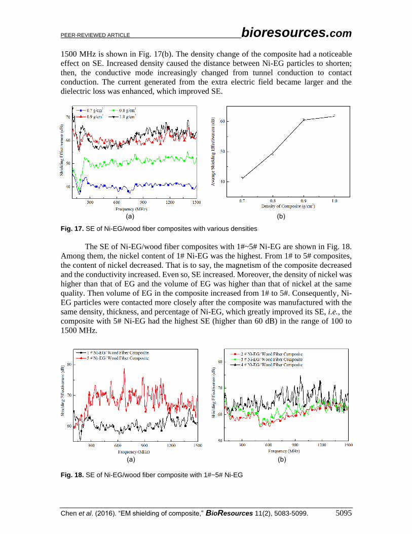
1500 MHz is shown in Fig. 17(b). The density change of the composite had a noticeable
effect on SE. Increased density caused the distance between Ni-EG particles to shorten;
then, the conductive mode increasingly changed from tunnel conduction to contact
conduction. The current generated from the extra electric field became larger and the
dielectric loss was enhanced, which improved SE.
(a) (b)
Fig. 17. SE of Ni-EG/wood fiber composites with various densities
The SE of Ni-EG/wood fiber composites with 1#~5# Ni-EG are shown in Fig. 18.
Among them, the nickel content of 1# Ni-EG was the highest. From 1# to 5# composites,
the content of nickel decreased. That is to say, the magnetism of the composite decreased
and the conductivity increased. Even so, SE increased. Moreover, the density of nickel was
higher than that of EG and the volume of EG was higher than that of nickel at the same
quality. Then volume of EG in the composite increased from 1# to 5#. Consequently, Ni-
EG particles were contacted more closely after the composite was manufactured with the
same density, thickness, and percentage of Ni-EG, which greatly improved its SE, i.e., the
composite with 5# Ni-EG had the highest SE (higher than 60 dB) in the range of 100 to
1500 MHz.
(a) (b)
Fig. 18. SE of Ni-EG/wood fiber composite with 1#~5# Ni-EG

PEER-REVIEWED ARTICLE bioresources.com
Chen et al. (2016). “EM shielding of composite,” BioResources 11(2), 5083-5099. 5096
In summary, when the type of Ni-EG, percentage of Ni-EG, thickness, and density
of the composite were set to 5#, 60 %, 2 mm, and 0.9 g/cm3, respectively, the composite
had the highest SE (higher than 60 dB) in the range of 100 to 1500 MHz.
Reflectivity of the Composite The complex permittivity and complex permeability of EG are both low, so it has
almost no loss function for electromagnetic waves. However, nickel has a high complex
permeability and could therefore absorb electromagnetic waves. As the content of nickel
in the composite increased, the peak of reflectivity decreased (as the value decreased, the
ability to absorb electromagnetic waves improved). The reflectivity of 1# and 5# Ni-
EG/wood fiber composites when the percentage of Ni-EG, thickness, and density of the
composite were set to 60 %, 2 mm, and 0.9 g/cm3, respectively, is shown in Fig. 19. Both
types of composites had a peak in the range of 9.5 GHz, but the peak of 1# Ni-EG/wood
fiber composite was −3.6 dB, which was less than −1.8 dB in the peak of 5# Ni-EG/wood
fiber composite.
Fig. 19. Reflectivity of Ni-EG/wood fiber composite with 1 # and 5 # Ni-EG
CONCLUSIONS
1. The optimal formula and processing conditions for electroless nickel plating on EG
were N2H4·H2O at 60 g/L, NiSO4·6H2O at 20 g/L, Na3C6H5O7·2H2O at 50 g/L,
CH3COO Na·H2O at 40 g/L, pH 11, and a temperature of 90 °C, which yielded a nickel
coating quality of 3.57 g/L of plating solution.
2. 1# Ni-EG made with a 2 g/L concentration of EG had a higher electromagnetic
performance, i.e., a magnetic property of 29.5 emu/g, and a resistivity of 80.2 mΩ·cm.
However, the magnetic property and resistivity of 5# Ni-EG made with a 10 g/L
concentration of EG was 5.57 emu/g and 10.7 mΩ·cm, respectively. Results showed
that higher EG concentrations yielded a lower nickel coating quality of Ni-EG and a
better conductivity of Ni-EG, but the magnetic properties declined slightly.
3. When the type of Ni-EG, percentage of Ni-EG, and thickness and density of the
composite were set at 5#, 60 %, 2 mm, and 0.9 g/cm3, respectively, the composite had
a better SE (higher than 60 dB) in the range of 100 to 1500 MHz, but the reflectivity
was only −1.8 dB in the range of 2 to 18 GHz. When the type of Ni-EG was 1#, the SE
of the composite was higher than 55 dB and the reflectivity was −3.6 dB. The results
PEER-REVIEWED ARTICLE bioresources.com
Chen et al. (2016). “EM shielding of composite,” BioResources 11(2), 5083-5099. 5097
indicated that the introduction of nickel is conducive to improving the absorbing
performance of Ni-EG/wood fiber composite and it has better SE in a broad frequency
range.
ACKNOWLEDGMENTS
This work was partially supported by the Guangxi Provincial Scientific Research
Foundation (No. 14122005-37) and the Innovation Project of Guangxi Graduate Education
(No. YCSZ2015052). The authors are grateful to the Scientific Agency of Guangxi
Province and the Education Agency of Guangxi Province for the financial support of this
work.
REFERENCES CITED
Ahuja, Y. R., Jahan, P., and Bhargava, S. C. (1999). “Epidemiological and laboratory
studies on the cancer risk from electromagnetic fields: An overview,” Proceeding of
the International Conference on Electromagnetic Interference and Compatibility,
December 6-8, New Delhi, India, pp. 459-464.
Brosseau, C., Mdarhri, A., and Vidal, A. (2008). “Mechanical fatigue and dielectric
relaxation of carbon black/polymer composites,” Journal of Applied Physics 104(7),
074105. DOI: 10.1063/1.2988269
Bulasara, V. K., Uppaluri, R., and Purkait, M. K. (2012). “Effect of ultrasound on the
performance of nickel hydrazine electroless plating baths,” Materials and
Manufacturing Processes 27(2), 201-206. DOI: 10.1080/10426914.2011.566663
Christian, B., and Philippe, T. (2005). “Instrumentation for microwave frequency-domain
spectroscopy of filled polymers under uniaxial tension,” Measurement Science &
Technology 16(9), 1823-1832. DOI: 10.1088/0957-0233/16/9/015
Dhakate, S. R., Sharma, S., Borah, M., Mathur, R. B., and Dhami, T. L. (2008).
“Development and characterization of expanded graphite-based nanocomposite as
bipolar plate for polymer electrolyte membrane fuel cells (PEMFCs),” Energy &
Fuels 22(5), 3329-3334. DOI: 10.1021/ef800135f
GJB 2038 (1994). “Methods for measurement of reflectivity of radar absorbing material,”
China Commission of Science Technology and Industry for National Defense,
Beijing, China.
Gnidakouong, J. R. N., Kim, M., Park, H. W., Park, Y. B., and Jeong, H. S. (2013).
“Electromagnetic interference shielding of composites consisting of a polyester
matrix and carbon nanotube-coated fiber reinforcement,” Composites Part A Applied
Science & Manufacturing 50(7), 73-80. DOI: 10.1016/j.compositesa.2013.03.007
Hou, J. F., Fu, F., Lu, K. Y., and Chen, L. Z. (2015). “Highly conductive fiberboards
made with carbon and wood fibers,” BioResources 10(4), 6348-6362. DOI:
10.15376/biores.10.4.6348-6362
Huang, J. T. (2005). “The effect of plating solution composition on wood electroless
nickel plating depositing rate,” Journal of Inner Mongolia Agricultural University
(Natural Science Edition) 26(1), 57-60. DOI: 10.3969/j.issn.1009-3575.2005.01.015
Huang, J. T., and Zhao, G. J. (2006). “Effects of technological parameters on nickel
deposition rate on wood by electroless plating method,” China Wood Industry 20(1),
15-17. DOI: 10.3969/j.issn.1001-8654.2006.01.005

PEER-REVIEWED ARTICLE bioresources.com
Chen et al. (2016). “EM shielding of composite,” BioResources 11(2), 5083-5099. 5098
Huang, Y., Xu, Z., Shen, J., Tang, T., and Huang, R. (2007). “Dispersion of magnetic
metals on expanded graphite for the shielding of electromagnetic radiations,” Applied
Physics Letters 90(13), 133117. DOI: 10.1063/1.2718269
Hui, B., Li, J., and Wang, L. (2014). “Electromagnetic shielding wood-based composite
from electroless plating corrosion-resistant Ni-Cu-P coatings on Fraxinus
mandshurica veneer,” Wood Science and Technology 48(5), 961-979. DOI:
10.1007/s00226-014-0653-0
Kim, H., Kim, M. K., Lee, C. Y., Joo, J., Cho, S. J., Yoon, H. S., and Epstein, A. J.
(2004). “Electrical conductivity and electromagnetic interference shielding of
multiwalled carbon nanotube composites containing Fe catalyst,” Applied Physics
Letters 84(4), 577-589. DOI: 10.1063/1.1641167
Kim, S. S., Kim, S. T., Yoon, Y. C., and Lee, K. S. (2005). “Magnetic, dielectric and
microwave absorbing properties of iron particles dispersed in rubber matrix in
gigahertz frequencies,” Journal of Applied Physics 97, 10F905. DOI:
10.1063/1.1852371
Kratochvíla, J., Boudenne, A., and Krupa, I. (2013). “Effect of filler size on
thermophysical and electrical behavior of nanocomposites based on expanded
graphite nanoparticles filled in low-density polyethylene matrix,” Polymer
Composites 34(2), 149-155. DOI: 10.1002/pc.22387
Li, C. Q., Wang, S. C., and Zhou, Y. F. (2014). “Study on manufacture of copper coated
expanded graphite,” Journal of Heilongjiang University of Science and Technology
24(5), 500-502. DOI: 10.3969/j.issn.2095-7262.2014.05.013
Liu, X. M., and Fu, F. (2009). “Study on performance of electro-conductive powder and
veneer composite,” Journal of Nanjing Forestry University (Natural Science Edition)
33(2), 95-98. DOI: 10.3969/j.issn.1000-2006.2009.02.023
Liu, H., Li, J., and Wang, L. (2010). “Electroless nickel plating on APTHS modified
wood veneer for EMI shielding,” Applied Surface Science 257(4), 1325-1330. DOI:
10.1016/j.apsusc.2010.08.060
Lozano, K., Espinoza, L., Hernandez, K., Adhikari, R., and Radhakrishnan, G. (2009).
“Investigation of the electromagnetic interference shielding of titanium carbide
coated nanoreinforced liquid crystalline polymer,” Journal of Applied Physics
105(10), 103511. DOI: 10.1063/1.3130397
Lu, K. Y., Fu, F., Cai, Z. Y., Fu, Y. J., and Zhang, Y. M. (2011). “Study of properties of
electromagnetic shielding plywood laminated with conductive sheets,” Journal of
Building Materials 14(2), 207-211. DOI: 10.3969/j.issn.1007-9629.2011.02.012
Maiti, S., Shrivastava, N. K., Suin, S., and Khatua, B. B. (2013). “Polystyrene/MWCNT
/graphite nanoplate nanocomposites: Efficient electromagnetic interference shielding
material through graphite nanoplate–MWCNT–graphite nanoplate networking,” ACS
Applied Materials & Interfaces 5(11), 4712-4724. DOI: 10.1021/am400658h
Polák, J., and Petráš, R. (2015). “Hysteresis loop analysis in cyclically strained
materials,” Advanced Structured Materials 57, 185-205. DOI: 10.1007/978-3-319-
14660-7_10
Qin, F. X., and Brosseau, C. (2012). “A review and analysis of microwave absorption in
polymer composites filled with carbonaceous particles,” Journal of Applied Physics
111(6), 061301. DOI: 10.1063/1.3688435
Ren, Q. F., Jia, Y., and Zhang, Q. Y. (2009). “Property of electroless nickel plating on
expanded graphite,” Chinese Journal of Applied Chemistry 26(4), 495-497. DOI:
10.3969/j.issn.1000-0518.2009.04.029

PEER-REVIEWED ARTICLE bioresources.com
Chen et al. (2016). “EM shielding of composite,” BioResources 11(2), 5083-5099. 5099
SJ 20524 (1995). “Measuring methods for shielding effectiveness of materials,” The
Ministry of Industrial Electronics of The People’s Republic of China, Beijing, China.
Su, C. W., Yuan, Q. P., Gan, W. X., Dai, D., Huang, J., and Huang, Y. (2012). “Study on
a composite fiberboard with multiple electromagnetic shielding effectiveness,” The
Open Materials Science Journal 6, 44-49. DOI: 10.2174/1874088X01206010044
Su, C. W., Yuan, Q. P., Gan, W. X., Huang, J. D., and Huang, Y. Y. (2013). “The
research on wood fiber/stainless steel net electromagnetic shielding composite
board,” Key Engineering Materials 525, 437-440. DOI:
10.4028/www.scientific.net/KEM.525-526.437
Sun, G., C., Liu, Z., L., and Yao, K., L. (2000). “Influence of the constitutive parameters
of helical chiral materials on the electromagnetic wave rotation,” Journal of
Functional Materials 31(1), 38-39. DOI: 10.3321/j.issn:1001-9731.2000.01.012
Wang, L. J., Li, J., and Liu, Y. X. (2005). “Surface characteristics of electroless nickel
plated electromagnetic shielding wood veneer,” Journal of Forestry Research 16(3),
233-236. DOI: 10.1007/BF02856822
Xu, Z., Huang, Y. A., Yang, Y., Shen, J., Tang, T., and Huang, R. (2010). “Dispersion of
iron nano-particles on expanded graphite for the shielding of electromagnetic
radiation,” Journal of Magnetism and Magnetic Materials 322(20), 3084-3087. DOI:
10.1016/j.jmmm.2010.05.034
Yavuz, Ö., Ram, M. K., Aldissi, M., Poddar, P., and Srikanth, H. (2005). “Polypyrrole
composites for shielding applications,” Synthetic Metals 151(3), 211-217. DOI:
10.1016/j.synthmet.2005.05.011
Yu, X., and Shen, Z. (2009). “The electromagnetic shielding of Ni films deposited on
cenosphere particles by magnetron sputtering method,” Journal of Magnetism and
Magnetic Materials 321(18), 2890-2895. DOI: 10.1016/j.jmmm.2009.04.040
Yuan, Q. P., Su, C. W., Huang, J. D., Gan, W. X., and Huang, Y. Y. (2013). “Process and
analysis of electromagnetic shielding in composite laminated with electroless nickel-
plated carbon fiber,” BioResources 8(3), 4633-4646. DOI: 10.15376/biores.8.3.4633-
4646
Yuan, Q. P., Lu, K. Y., and Fu, F. (2014). “Process and structure of electromagnetic
shielding plywood composite laminated with carbon fiber paper,” The Open
Materials Science Journal 8, 99-107. DOI: 10.2174/1874088x01408010099
Yusoff, A. N., and Abdullah, M. H. (2004). “Microwave electromagnetic and absorption
properties of some LiZn ferrites,” Magn. Magn. Mater 269(2), 271-280. DOI:
10.1016/S0304-8853(03)00617-6
Zhang, X. Q., Liu, Y. X., and Li, J. (2004). “Wood fiber and iron wire netting composite
MDF,” Journal of Northeast Forestry University 32(5), 15-19. DOI:
10.13759/j.cnki.dlxb.2004.05.010
Zhao, F. C. (2001). “Development of electromagnetic shielding materials,” Development
and Application of Materials 16(5), 29-33. DOI: 10.3969/j.issn.1003-
1545.2001.05.009
Zhao, J. J., Li, X. X., Guo, Y. X., and Ma, D. Y. (2014). “Highly exfoliated graphite
prepared by two-step intercalation and its microstructure,” Ordnance Material
Science and Engineering 37(4), 4-8. DOI: 10.3788/OPE.20142205.1267
Article submitted: November 27, 2015; Peer review completed: February 6, 2016;
Revised version received and accepted: April 9, 2016; Published: April 21, 2016.
DOI: 10.15376/biores.11.2.5083-5099