electrohydraulic control for boiler ... electroihydraulic control for boiler feedpump turbines...
TRANSCRIPT

1 GEK-15019
ELECTROHYDRAULIC CONTROL
FOR
BOILER FEEDPUMP TURBINES
3S7513TC300
Proprietary information of ,GeneraI Electric Company furnished
for customer use only. No other uses are authorized without the written permission of General Electric Company.
GENERAL@ ELECTRIC

GEK-15019 Electrohydraulic Control For Boiler Feedpump Turbines
TABLE OF CONTENTS
INTRODUCkION ...........................................................
RECEIVING, HANDLING AND STORAGE .....................................
DESCRIPTION ........................ ..................................
Speed Reference Or Set Point ........................................... Inverters ...........................................................
INSTALLATION AND ADJUSTMENT .........................................
OPERATION ...........................................................
MAINTENANCE ................................................ ...........
TROUBLESHOOTING .................. ................ ...................
RENEWAL PARTS .......................................................
5
5
2

GEK-MOI9
ELECTROIHYDRAULIC CONTROL FOR
BOILER FEEDPUMP TURBINES 3S7513TC30U INTRODUCTION
The electronic portion of an Electrohydraulic Control system for a boiler feedpump turbine drive is de- scribed in these instructions.
Any adjustment or maintenance of this equipment should be performed either by qualified turbine per- sonnel or supervised by such personnel.
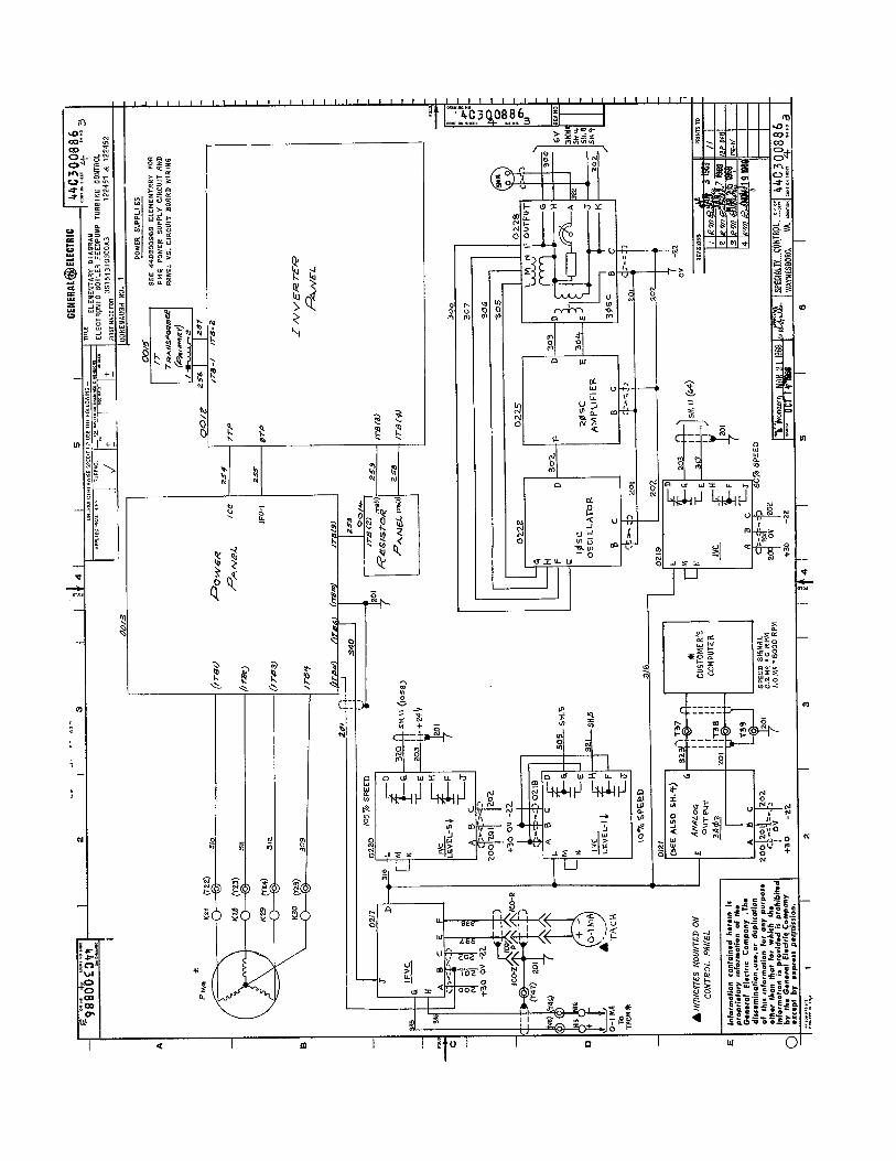
Drawing 44C3006’79 is a block diagram of a typical unit and is referred to later. This equipment is an electronic speed governor whose speed set point can be varied by an automatic boiler controller or by an operator from a remote control unit. Electronic redundancy and mechanical overspeed trip are used to provide a high degree of reliability and safety.
A block diagram, elementary diagram, and alignment diagram for a particular unit are included in these instructions. Since both the number and arrangement of auxiliary components vary with particular appli- cation, it is necessary to refer to the drawings fur- nished tith each equipment to determine the correct connections and auxiliary components furnished in each instance.
RECEIVING, HANDLING
AND STORAGE
RECEIVING AND BANDLING
Immediately upon receipt, the equipment should be carefully unpacked to avoid damaging the apparatus. Particular care should be exercised to prevent small parts being mislaid or thrown away in the packing material.
As soon as the equipment is unpacked it should be ex- amined for any damage that might have been sustained in transit. If injury or rough handling is evident, a damage claim shall be filed immediately with the trans- portation company and the nearest General Electric Sales Office should be notified promptly.
STORAGE
If the equipment is not to be used as soon as it is un- packed, it should be stored in a clean dry place and protected from accidental damage. Particular care should be exercised to avoid storing the equipment in locations where construction work is in progress.
DESCRIPTION The speed control loop will be described-first. Start- ing outside the electronic control unit on the right hand side of block diagram 44C300679 an electro- hydraulic valve receives a low power electrical
signal from the electronic unit and cantrols the fIow of oil to a double acting hydraulic cylinder which positions the turbine steam controI vaIve. Turbiie speed is sensed by two magnetic sensors mounted near the periphery of a shaft driven gear. Pulses whose frequency is direct@ proportional: to turbine speed are generated as each gear tooth passes a sensor. Primary and secondary speed &anneIs in the electronic control produce a DC v&age propor- tional to the frequency of the ssnsar outputs. Q&puts of the two speed channels are fed into high valve gate number, one which rejects the lower of the two speed signals and passes on the higher Muod ~&ME, This redundancy permits one channel to fail withvut sig- nificantly affecting turbine speed, The secondary channel is adjusted for an output, 1% Less than the primary channel. It is therefore UncontroIIing, except in case of failure of the primary charmsI or if a “Backup Amplifier Test” switch in the cabinet is actuated which increases the output of the secondary channel to 1% greater than the primary channef. A test meter in the cabinet can be used to determine the controlling channeI.
The speed signal from high v&e gate one is summed with the speed set point to obtain a speed error. See the middle of the block diagram. The speed error is passed through a stabiIity compensation and error amplifier, which includes a reguIation adjustment to obtain a valve lift demand sign& This is summed with a valve position signaI to obtain a valve position error which is passed through the servo ItmpIifIer to the servo valve. IncreasZng the speed set writ: increases valve lift demand, valve position error, and valve opening. Speed will increase until the rise matches the set point increase.
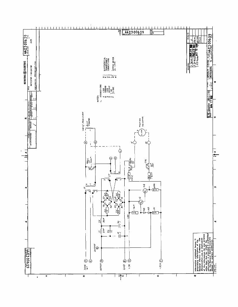
The valve position signal is obtained from a linear variable differential transformer (LVDT) whose core is positioned by the controI vaIve. Three kiIohertz excitation for the LVDT is generated in the electronic cabinet. A demodulator in the cabinet praduces a DC signal proportional to the AC output of the LVDT which varies with core position,
The electronic control unit aDpEes a strong ebse signal to the servo valve in the tripped eon&@on. Before the control can be reset, it must generate a close valve signal from the governor. IXeIay circuit- ry also requires that the ebzctrical connectors must be plugged into the servo valve, the WDT, and the speed sensors before starting. The LVDT‘ signaI. is biased to close the control valve if the LVDT co&nec- tar is removed with the turbine running, The servo valve contains a 5% mechanical. b&s which wiI1 close the control valve in the absence of an electricd signal.

GEK-15019 Electrohydraulic Control For Boiler Feedpump Turbines
SPEED REFERENCE OR SET POINT
Identical motor driven LVDT’s are used to generate the manual and automatic speed references. The core position is varied by a two-phase stepping motor which moves in discrete steps and locks in position when not running. Raise and Lower pushbuttons on the operator’s manual control panel cause the ref- erence to run from stop to stop in 80 to 90 seconds. Raise Fast and Lower Fast pushbuttons will run the reference from stop to stop in approximately 10 seconds. The automatic speed reference circuits contain interface circuitry for compatibility with a specific boiler controller. The automatic and manual speed references are fed into a low value gate which rejects the higher reference and passes on the lower reference to control turbine speed. A relay operated from this gate indicates which of the two references is controlling.
An overspeed test can be performed after first running both manual and automatic references to the high speed stop. The operator’s overspeed test pushbutton is then actuated causing an additional speed reference to be generated which increases linearly with time at approximately 12% speed per minute. This is added to both manual and automatic references. Once the speed ramp starts, a relay energizes a lamp to in- dicate that a high reference condition exists. If tur- bine speed rises to 120% of rated, a speed signal will override the ramp generator and prevent further speed increase. Upon release of the Test pushbutton, the reference ramps back to normal at the same rate ‘as it increased.
The control cabinet includes circuitry for driving position indicators from LVDT’s mounted on the stop valves, but this circuitry is not a part of the governor.
Two rectifier-inverter-rectifier power supplies pro- vide necessary DC voltages to the electronics. For startup and operating backup power, one supply is fed from 115 volts, 60 Hz, 1 phase. For primary operating power independent of the AC line, power is obtained from a turbine driven 3-phase permanent magnet generator (PMG).
The PMG also drives a frequency to voltage converter for a tachometer and operates speed relays. A 10% speed relay is combined with the output of speed signal highvalue gate 2 to cause the speed reference to go to zero if the PMG is above 10% speed and neither primary or secondary speed channel is working. Above 60% speed a relay unlocks the alarms on the PMG power supplies. Above 105% speed a relay un- locks the lock out valve in the emergency trip exerciser scheme.
INVERTERS
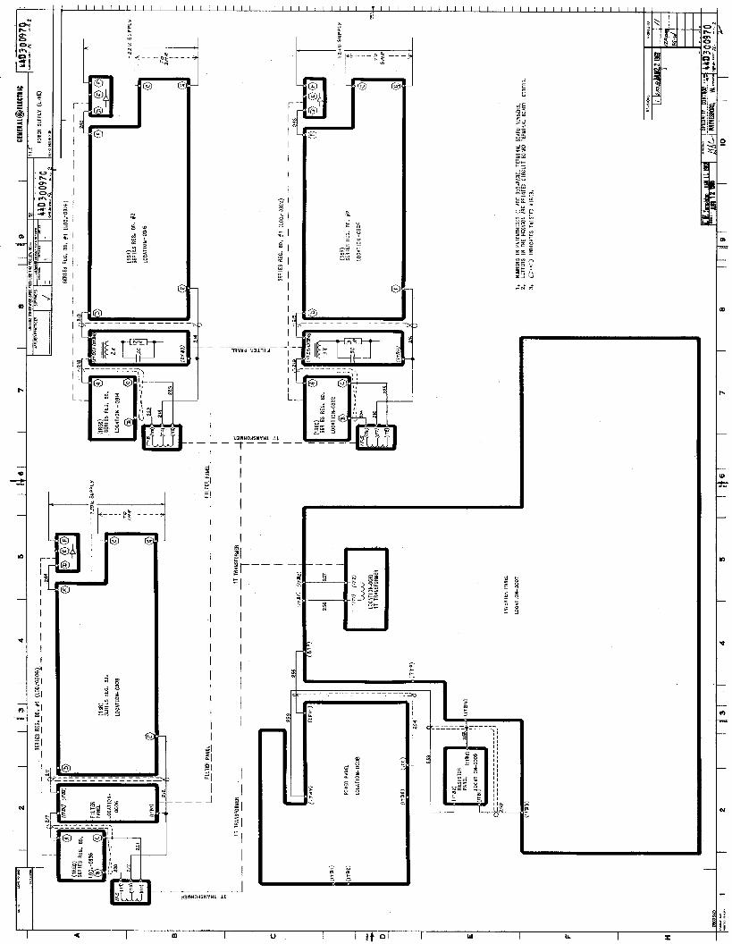
Diagram 44D300970 shows the inverter components. Incoming AC power at C, l-2 feeds transformer 2T.
6
The output of 2T is rectified and filtered to obtain an operating DC bus level of 100 to 200 volts. Power elements of the inverter consist of l-4 SCR thy- ristors together with commutating reactors, diodes, and capacitors which produce square-wave AC on the primary of transformer 1T. 1T has three sec- ondaries whose outputs are rectified, filtered, and fed through series regulators. Thyristors 1 and 2 are operated as a pair such that when either is being fired the other is not fired. Thyristors 3 and 4 are operated similarily. Starting with 1 and 3 conduct- ing and 2 and 4 non-conducting both points B and C are at DC bus level A and no voltage appears across the primary of 1T. 2SCR is then fired placing voltage B on 3-4 of 1X. By transformer action this voltage also appears on l-2 of 1X which places 1 of 1X at twice voltage A to reverse bias and turn off lSCR, capacitor 3C quickly discharges through 2 SCR and 1X to zero volts at B. Voltage now appears on 1T primary with C positive with respect to B. This voltage is integrated and when the desired volts- seconds on 1T is obtained 4 SCR is fired. 3 SCR is commulated off, and the voltage at C then goes to zero and the voltage on 1T is again zero. A frequen- cy controlling master flip-flop then fires 1 SCR to raise B to bus level A which reverses the polarity of the voltage previously applied to 1T. Point B is now positive with respect to C. After accumulation of the required volt-seconds, 3 SCR is fired and point C raised to level A which completes one full cycle of the inverter.
Firing circuits l-4 FC for the thyristors are shown by dotted blocks just below the bridge circuit and are shown in detail in the lower right corner. A 47 volt bus for the firing circuits is obtained from the DC bus through 2R and 1 ZD. Each firing circuit is a transistorized, transformer coupled blocking oscillator operating at 25 kHz to 100 kHz. A half-wave rectifier on the transformer output winding feeds the associated thyristor gate with pulses at the oscillating frequency. The circuit will oscillate in the absence of a control signal and stop oscillating when a signal is applied.
The inverter control circuitry diagram is shown on the lower portion of diagram 44D300970 from left to right. A 24 volt control bus is obtained from the DC bus through 1R and Zener diode 2 ZD.
The inverter output frequency is approximately 200 Hz is exactly half the frequency of the relaxation oscillator composed of 4C, 4R, lSUS, and 1X. Capac- itor 4C charges through resmtor 4R until its voltage equals the break down voltage of silicon unilateral switch 1SUS. When 1SUS breaks down, the voltage drops to a low value placing 4C voltage on 1X and turning on 1Q for approximately 20 microseconds until the discharge of 4C and inductive reversal of voltage on 1X turns off 1Q and 1SUS. Capacitor 4C then begins to charge again. Each conduction pulse of 1Q triggers master flip-flop lQ-2Q, switching conduction of 1SCR and 2SCR to initiate a half cycle

Electrohydraulic Control For Boiler Feedpump Turbines GEK-15019
TYPICAL CABINET
Figure 1 GEK-15019

GEK-15019 Electrohydraulic Control For Boiler Feedpump Turbines
TYPICAL OPERATORS CONTROL UNIT Figure 2
GEK-15019

Electrohydraulic Control For Boiler Feedpump Turbines GEK-15619
of inverter output voltage. The end of each half cycle of output is obtained from switching conduction of 3-4 SCR by slave flip-flop 7Q-8Q.
Regulation of the output volt seconds is obtained from 3D through 8D, 4Q, 5Q, SQ, 17Q, and associated components. Voltage waveforms for the output, flip- flops, 5-ID diodes, and4Q, 5Q are shown in Figure 3.
Only during periods of output voltage is 5Q turned off and 8C allowed to charge. The voltage on 8C is the time integral of the current into it, which comes from the DC bus through 16R, 23R, and 1 P.
Transistors SQ and 17Q trigger on when the capacitor voltage rises above the SQ base voltage. The dis- charge of 8C generates a spike on 17 R to trigger slave flip-flop 7Q-8Q ending the half cycle of output voltage.
The remainder of the inverter control components shown to the right of slave flip-flop 7Q-8Q are used to obtain correct start-up of the inverter. When power is applied and voltage begins to build up on the DC bus, it is initially too low to cause conduction of 9Q. With 9Q off, 1OQ is on, 12Q off, 13Q on, 14Q off, 15Q on and 16Q on. With 14Q off,its high col- lector voltage is coupled through 4’7R and 49R to 2FC and 4FC to inhibit firing of 2 and 4 SCR, letting the voltage on B and C rise with the bus voltage. With 16Q on, it feeds a relatively high current into BC causing it to reach firing voltage very quickly so that the slave flip-flop remains in the output voltage state for a very short period. As the DC bus con- tinues to rise, it reaches the point where 9Q conducts. This turns off 1OQ raising the voltage on the base of I2Q but not enough to cause conduction. Following this, the first flip of the master flip-flop to the 2Q on state is capacitively coupled to 11Q through 11C to momentarily turn it off, allowing its collector to rise and raise the base of 12Q high enough to turn it on and turn off 13Q. The emitter voltage drops and 12Q remains on when the pulse from 11Q disappears. With 13Q off, 14Q is on and 2FC and 4FC are no longer inhibited from firing. 4SCR fires and a short duration output is obtained, quickly ended by the rel- actively high current into 8C triggering the state of the slave flip-flop to the no output voltage condition. With 14Q on 15Q is off and 13C begins to discharge, reducing the current from 16Q into 8C. The time for 8C to reach firing voltage of 6Q-l?Q is increased as is the width of the output voltages waveform until 16Q stops conducting. At this time normal operation has been obtained. The only adjustment, 1P is set for 38 volts into the 30 volt series regulator.
The series regulator for the 30 volt supply is shown at the top of the diagram. The other two are identical. output of the voltage sensing bridge consisting of 15R 16R, 17R, 1P and 2ZD is fed to 7Q and 8Q. An in- crease in output voltage raises the voItage on 8Q, in - creasing its conduction and lowering conduction of 7Q. Decreased current in 7Q decreases
current in 4Q, 5Q, and 6Q dropping the output voltage until balance is restored. Excessive current output through 16R turns 3Q on ZQ off, and 1Q on, grounding the base of 7Q. With ‘IQ off, series regulators 4Q , 5Q, and SQ are off and the output goes to zero. When XC! discharges, 3Q is turned off and output is restored. The circuit will oscillate between off and on until the cause of the high current is removed.
INSTAlLATlON AND ADJUSTMENT
The electronic control cabinet should preferabiy be mounted in a clean dry air conditioned environment. Ambient temperature should not exceed 104” F unless otherwise noted on the outline drawing for a specific unit.
Equipment adjustment and the required test equipment are covered in detail in an alignment diagram and alignment instructions furnished with each unit. See 440302362 and 44A301479 for typic& drawings.
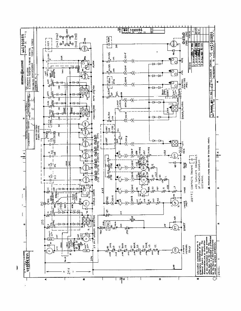
The location of sub assembIies within the cabinet is shown on the internal connection diagram furnished with each control. Printed circtit board locations are shown on sheets 1 and 2 of the elementary diagram, see 44C300886.
OPERATION
Refer to the instruction book for the turbine.
MAINTENANCE No periodic maintenance is required. Outage time due to component failure is best minimized by main- taining a complete set of spare parts. Elementary diagrams of the printed circuit boards a e included in this instruction book. The assembly drawings showing component location on the printed circuit boards are furnished with each order except where component identifications are silk screened on the boards in which case assembly drawings are not furnished.
TROUBlESHUOT#M5
Most troubleshooting problems can be qtickly isola- ted to a particular section of the co&d by use of the built-in test meter, the meter relays, and alarm lights. These used in conjunction with the alignment diagram indicate the operating condition d each section. An oscilloscope is recommended for Pin- pointing a defective component or components. Each printed circuit board can be removed from the rack for servicing without disconnection due to the use of terminal boards.
7

GEE-15019 Electrohydraulic Control For Boiler Feedpump Turbines
RENEWAL PARTS When ordering renewal parts, address the nearest c. If possible, data on orginal order on which Apparatus Sales Office of the General Electric Company equipment was first supplied, including all numer- and supply the following information. ical references.
a. Catalog number stamped on the part and a complete description of the part, including its use and location.
b. Complete nameplate data appearing on the assembly of which the part is a component.
Since operation of a steam turbine-generator is de- pendent upon operation of the feedpump control, it is suggested that an adequate stock of spare parts be carried on hand to minimize outage time due to component failure.
--I ,-” & 3Q COLLECTOR //
I 1 1 -o- C & 89 COLLECTOR
/+ 2Q COLLECTOR 1 )
1 I I 1 1 [ 0-7Q COLLECTOR
3D- 8D JUNCTION
--O- (20~8~)
1 rImo- TiQT790P) JUNCTION
6D-770 JUNCTION
-O-
]--j n rL-,:Q COLLECTOR
1 /1 /1 / 5Q COLLECTOR
FIG. 3 Inverter Waveforms
I 1)
t
+
OEllERAL@ELECtRiC 44A300242 ;'d: 0 TITLE ’ COUT ON SWEE, SW NO
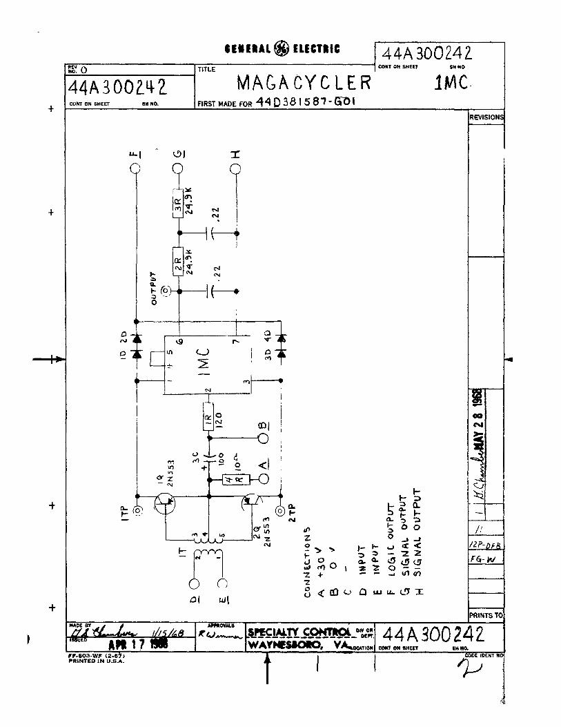
@IA300242 - MAGACYCLER IMC- CON1 ON SHEET SH NO. IFlRsTMADEFOR44D38)587'6;0(
I
t
t-
t
EVISiON
‘RINTS T( I -ov*Ls $ww COtma owon 44 A 300 24 --------------- DECT.
wAv*-, v&OOATlON CONT ON WEST 5l+ NO. ‘F-80%WF (Z-6+> ‘NINTED IN U.S.A.
I I
COGE IDENT WI

+
+
-
' 8EIEIAL@CLECTRM 44A 300243 E 0 TITLE - CONT ON SHEET SH NO.
DIODE BOARD ID0 CON1 ON SHEET 8” HO. FIRST MADE FOR ~~~2363~0-~0/
EVISION:
RINTS T(
+
+
1) I
t
+
0
#EUIRAl@ ELfCTIlC Q4A30026d :dl 0 TITLE
Eom UN SHEET SHUO.
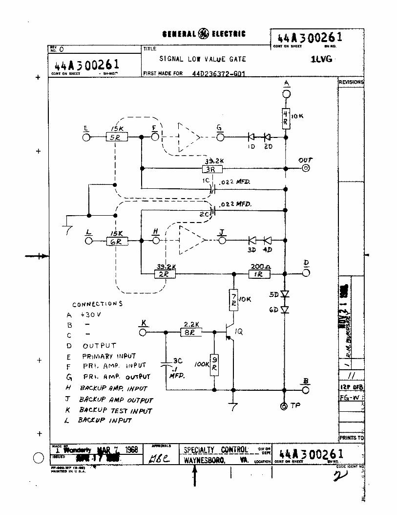
44A300261 51 GNAL LOW VALeuE GATE lu% .

+
+
I I)
t
,
+
C
CEHERAL @’ ELECTRIC 44A3 80262 I’d: 0 TITLE
CONT ON SHEET SH NO.
44A3 00262 OVERSPEED INTEGRATOR l~S1 . --
:ONT ON SHEET SH NO. FIRST MADE FOR 44D236373-GO1
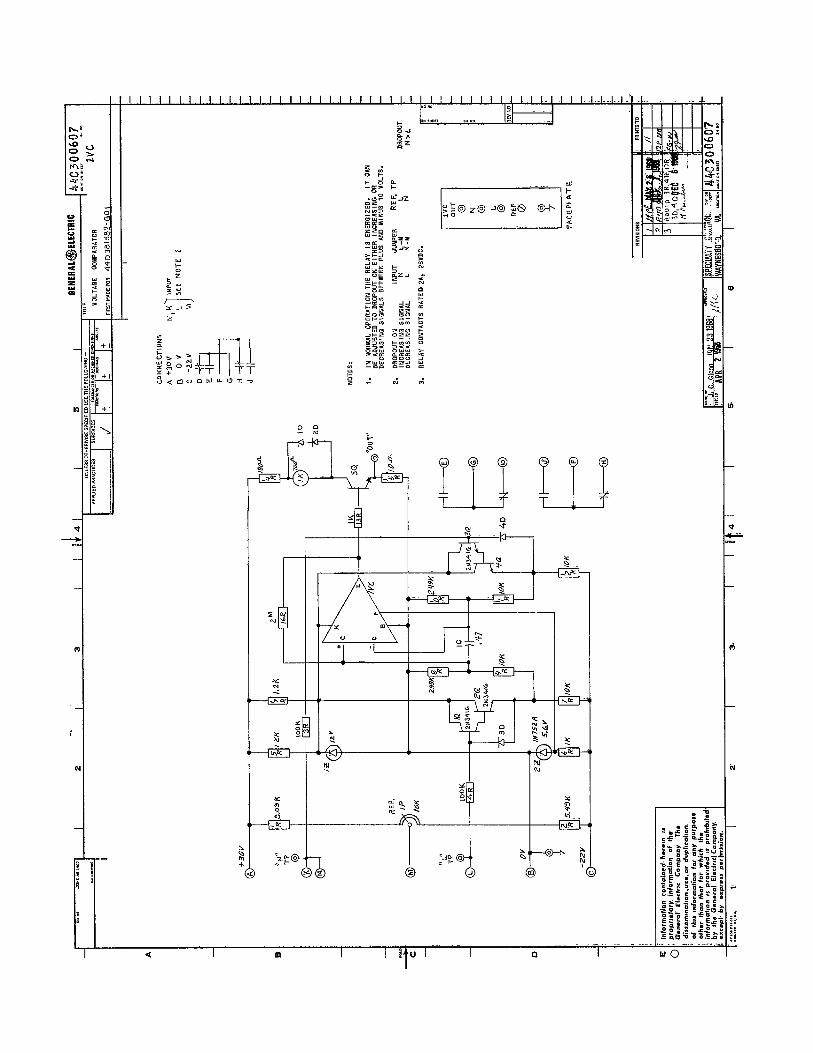
J 1. E - CON~\,ECTIONS
A\ +30J F AMPLlFIEP WTPUT
8 9 G AMPLIFIER ;h’?UT
c I\. . -. * tl pas. SUFF-y 7-Hi?Oilati RfLfw
D 0JrPU-T J NE& SJPPLY THPCJ j+.$ RELAY E SPEED SlGWAL
.
- :VISION5
Ip d ‘RINTS TO I %?iihanu#% MAR I 1968 APIROWLS
H%- SPECIALTY CONTROL DIVOR
_________ - - - ____ DEFT.
‘*S”Eo )ulf:2 5 II) WAYNESBORO, 44A3 00262 VA. LOCATION CONTON SHEET SH NO.
‘c-.os-wc (S-S., ‘“IWTLD IN ” 9 A
I I
CODE IDENT NO
P ,
4

CENERAL@ELECTflC ,
44R3002&1
To TITLE CON1 ON SHEET SH NO
REFERENCE LOW VALUE GATE (2LVG)
ONT ON SHEET SH NO. FIRST MADE FOR 44D2 36 378~Go’ GAIN 4P 20K /‘7k 56aZK +
M -
/.3 M I
G AMP. OIJTPUT,MANUAL -
1 CONNECT I ONi- A +3OV
H AMP.
B ov
I NPUT MANUAL
C
J OVERSPEED T&T INPUT
-22v D CLAMP E CLAMP F OUTPUT
K AMP. OUTPUT, AUTO L AMP. I NPUT, AUTO
N AUTO INPUT (s~GN.AL CQNVERTER)
c -
M MANUAL INPUT
CLAMP NOTE: ZERO VOLTS ON D OR E WILL HOLD OUTPUT (Fj AT ZEW, AD,fUSTMENT: I--- - 1: WR~-iiJTO I NPUT AT HSS AND MANUAL AT LSS, ADJUST BIAS FOR ZERO
OUTPUT AT F. 2: WITH BOTH GAINS MAX. (Clw) AND INPUTS AT HSS, AD&ST WANUAL GkzkN
FOR 5 VOLTS OUTPUT. 3: DECREASE AUTO GAIN UNTIL OUTPUT OF THE ASSOCIATED RWLfF!ER
SWITCHES NEGATIVE TO POSITIVE.
PECIALTY cob#Tml# “‘“,$ : --a------ 44bk30028 P
~hl#WJ?4 ! COW OU EHEET sH”ll0. ,
C.M.WC c...., I I CODE IDLW WC
1

+
+
.
I, I
t
+
887K 887 K 1 o--p? 3R }
0 ~ST RCG
@
0 REG
0
&WI-- 0947
i T
lEViSION
L
RINTS TC
SuED FEB 1 8 fg@ ’ ‘.303-WF m-07,
PRINTED IN U.S.A.
y*$z, .WW&TY CtMfTkXX ----------~-~~~D’LF~ bfm+m2JeQ 1 YA. LDCATION CDNT ON SHEET - 3” NO.
I I CODE iDENT NC

CEWEIAb@ELCCflllC 44A30 I479 I i \y TITLE . COHT OH SHCET 2 SH NO 1 t AL I GMMEUT I NSTRUCTl ONS
44A30 1479 ELECTRON1 C FEED PUMP TURBJNE CONTROL
CON1 ON SHEET 2 SH NO. I i FIRST MADE FOR 337513TC300A3, TURBINES 122451 & 122452
i - CONEMAUGH GROUP -
REVJSIONS
I REFERENCE AL I GNMENT D I AGRAM 44D30172Q
TEST EQU I PYENT 1. AUDIO OSCILLATOR: HEWLETT PACKARD 201C ZOOCD; GENERAL
RADIO 121OC OR EQUIVALENT. MINIMUM INTb 600 OHMS.
OUTPUT MUS+ BE 10 VOLTS RMS
i 2. AC/DC DIGITAL VOLTMETER: 0.1 MV TO 100 V MAX.
!
3. D I GI TAL FREQUENCY COUNTER: 6 VOLT RMS SENSITlVlTY. 30 TO 5000 HZ. I
4. TEN TURN POTENTIOMETER; NOT MORE THAN 5000 OHMS REStSTANCE.
5. TWO INPUT OSCILLOSCOPE, CALIBRATED SWEEP: Xl AND Xl0 PROBES.
6. OPTIONAL: BRUSH RECORDERjSPECl AL TESTS ARE DESIRED. t
7. VOLT - OHM - Ml LLI AMMETER
I. PRELIMINARY
1. CHECK INTERCONNECTION OF CONTROL CABI NET, OPERATOR’S CONTROL DEVICES, TURBINE DEVICES, ETC.
2. MECHANICALLY ZERO TEST METER IN CABINET AND OPERATOR’S TACHOMETER AND OTHER I NS TRUMENTS.
I. LINE POWER SUPPLY 12OV. 10, 60HZ, 1. l NVERTER 0UT:APPLY POWER AND ADJUST I NVERTER OUTPUT FOR
38 VOLTS AT D-k & E- IF lSR LOC, 0308, THE INVERTERS ARE I N THE BOTTOM OF THE CABI NET WI TH LI NE I NVERTER IN BACK AND PMG INVERTER I N FRONT.
2. DC SERIES REGULATORS: ADJUST POWER SUPPLIES AND METER CAL I BRATI ONS PER CHART
L I NE SUPPLY TEST POINTS APJUS T
+3ov BUS BARS 0308
-22’6 BUS BARS 0316
24V -t-F LOC. 0322;-G LOC. 0324 0324
3. METER RELAY ALARMS: VARY ALARM SET POI NT OF LINE SUPPLY METER RELAYS TO CHECK ALARM OPERATION. SET ALARMS FOR 95% AND 105%.
4
c---- DEPT. 44A30 1479
EEIEllAL@ELECTllt 44A30 1479 I<” I TlTl c CONT ON SHEET 3 SH NO 2 10
I I ILL
ALIGNMENT INSTRUCTIONS ’
44A30 1479 ELECTRONIC FEED PUMP TURBINE CONTROL
CON, ON SHEET3 SHNO. 2 FIRST MADE FOR 3S7513TC300A3, TURB I NES 122451 & 122 -
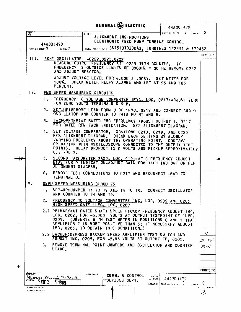
I I I. 3KHZ OSCILLATOR -0222.0225.0228 MEASURE OUTPUT FREQUENCY AT 0228 WITH COUNTER. IF FREQUENCY IS OUTSIDE LIMITS OF 3000HZ + 30 HZ REMOVE 0222 AND ADJUST REACTOR.
ADJUST VOLTAGE LEVEL FOR 6.000 + .006V. SET METER FOR 100%. CHECK METER RELFY ALARblS AND SET AT 95 AND 105 PERCENT.
I v. PYG SPEED MEASURI NC Cl RCU I TS
1. FREQUENCY TO VOLTAGE CONVERTER 1FVC. LOC. 0217: ADJUST ZERO FOR ZERO VOLTS TERMINALS D % B.
2. SET-UP:REMOVE LEAD FROM J OF 1FVC 0217 AND CONNECT AUDIO -ATOR AND COUNTER TO TH IS P0I NT AND B.
3. TACHOMETER:AT RATED PMG FREQUENCY ADJUST OUTPUT I 0217 FOR RATED RPM TACH INDICATION. SEE ALIGNMENT DIAiiRAhl.
4. SET VOLTAGE COMPARATOR, LOCATIONS 0218 0219 AND 0220 PER AL I GNMENT D I AGRAM. CHECK EACH SETflNG Bf SLOWLY VARYING FREQUENCY ABOUT THE OPERATING POINT. OBSERVE OPERATION WITH OSCILLOSCOPE CONNECTED TO THE OUTPUT TEST POINTS. RELAY DROPOUT IS 0 VO’LTS AND PICKUP APPROXIMATELY 0.3 VOLTS.
5. SECOND TACHOMETER 3A02. LOC. 0171: AT 0 FREQUENCY ADJUST BlAS FOR 0 INDICATION.ADJUST GAIN FOR TACH INDICATION PER ALIGNMENT ~1 AGRAM.
6. REMOVE TEST CONNECTIONS TO 0217 AND RECONNECT LEAD TO TERMINAL J.
J. SSPU SPEED MEASURI NG Cl RCU I TS
1. SET-UP:JUMPER T4 TO T7 AND T5 TO T8. -COUNTER TO T4 AND T5.
CONNECT OSC I LLATOR
2. FREQUENCY TO VOLTAGE CONVERTERS 1MC. LOC. 0202 AND 0205 HI GH SPEED GATE 1 LVG. LOC. 0209
2.1 PRIMARY;AT RATED SHAFT SPEED PICKUP FREQUENCY ADJUST 1MC Loc.02 FOR -5.000 VOLTS AT OUTPUT TESTPOINT OF 1LVG’ 0209. (OBSERVE WI TH TEST METER IN POSITIONS 6 AND 7 THAi. AMPLIFIER 7 IS MORE POSITIVE THAN 6; IF NECESSARY ADJUST WC, 0205, TO OBTAIN THIS CONDITION.)
2.2 BACKUP:DEPRESS BACKUP SPEED AMPLIFIER TEST SWITCH AND ADJUST lMC, 0205, FOR -5.05 VOLTS AT OUTPUT TP, 0209.
3. REMOVE TERMINAL POINT JUMPERS AND OSCILLATOR AND COUNTER LEADS.
52 LEVISIOR
I
‘RINTS T
ES DEPT. - OEPT 44A30 1479 LOCATION CON, ON SHEET 3 SH NO 2
FF 803 WF (2.(181 COLC lDLN1 r’ PRINTEO IN u s A.
.z
4

-t
+
i-
AL @ ELECTRIC 44A301479 1
I R E Y i NO 1 TITLE COW ON SHEET 4 SH NO
I AL I GNMENT I NSTRUCTI ONS 44A30 1479 ELECTRON1 C FEED PUMP TURBINE CONTROL
CON, ON SHLLT 4 5” NJ 3 FIRST MADE FOR 3S751 3TC300A3. TURBI NES 122451 & 122
VI. CONTROL VALVE RAM SERVO LOOP
:: CHECK LVDT CORE PER LEVE;oEIA;;fM. DETECTOR INDICATOR 1DI , . 6,: WI TH CONTROL VALVE FULL OPEN ADJUST NULL OF 1DI ‘FOR 0.00 f 0.01 VOLTS AT OUT TP. NOTE VOLTAGE READING ON ALIGNMENT DIAGRAM. WITH VALVE IN CLOSED OVERTRAVEL POSITION RECORD OUT TP VOLTAGE ON AL I GN. D! AG. ADJUST ZERO FOR 0 INDICATION OF CONTROL VALVE POSITION ON OPERATOR’S CONTROL CONSOLE. RETURN VALVE TO FULL OPEN POSI Tl ON AND ADJUST CAL I BRATE FOR 100% POSITION INDICATION.
3. DETERMINE GAIN OF DETECTOR CIRCUIT IN VOLTS PER INCH BY DI VI Dl NG THE DI FFEPENCE IN OUT TP VOLTS AT EXTREME VALVE POSI TI ONS BY THE TOTAL VALVE TRAVEL I N I NCHES, AND RECORD THIS FIGURE ON THE ALIGNMENT DIAGRAM.
4. MAKE ELECTRICAL CONNECTIONS TO SERVO VALVE. 5. SERVO AMPLIFIER. 2SA, LOC. 0214:
5.1* PSI0 TRlPfCHECK FOR APPROX. -0.7 VOLTS AT “1” TP UNDER TRIP CONDITION.
5.2 CLOSE S I GNAL CHECK: WI TH TURBI NE TR I PPED, DI SCONNECT DEMAND TERMINAL E AND LIFT TERMINAL D OF 2SA. CONNECT TEST POT WI TH NEGATI VE OUTPUT TO TERMINAL D AND SET POT FOR ABOUT -3 VOLTS AT LI FT TP. THE OUTPUT OF AMPL I FI ER 9 ON TEST METER POSITION 9 SHOULD BE ABOUT -10 VOLTS. TURN BI AS ADJUSTMENT CCW UNTIL AMP. 9 GOES TO +10 VOLTS. THERE SHOULD BE LITTLE OR NO CONTROL OF 9 AT INTERMEDIATE VOLTAGES. LEAVE 9 AT +I0 VOLTS AND RESET TURBINE. SLOWLY REDUCE TOWARDS 0 THE TEST POT SETTING AND NOTE THAT 9 SWINGS FROM j-10 TO A MINI MUM VALUE OF APPROX. -6.2 VOLTS. NOW APPLY MORE MEGATI VE VOLTAGE FROM THE TEST POT AND NOTE THAT 9 HAS A MAXIMUM VALUE OF APPROX. +6.2 VOLTS.
5.3 GAI N:DETERMI NE ‘IV” VOLTS LIFT/VOLT I FROM ALIGNMENT DI AGRAM. VARY THE TEST POT SETTING UNTIL I TP IS 0.000 VOLTS AND NOTE LIFT TP VOLTAGE. CHANGE THIS VOLTAGE WITH THE TEST POT BY +V VOLTS. ADJUST GAIN UNTIL I TP READS -1 .OOO VOLTS. RECHECK 0 POINT, THEN CHANGE LIFT VOLTAGE 6Y -V VOLTS AND NOTE THAT I TP IS t1.000 VOLTS.
5.4 81 AS’ DISCONNECT TEST POT AND RECONNECT THE LEAD REMOVED FRO.D. WITH THE VALVE IN THE CLOSED OVERTRAVEL POSITION ADJUST El AS FOR -0.035 VOLTS AT I TP. RECONNECT TERMI NAL E.
6, AFTER REMOVING THE ELECTRICAL CONNECTOR, MOUNT THE SERVO VALVE AND VER I FY THAT THE MECHANICAL BI AS I S I N THE VALVE CLOSING DIRECTION.
.- & CONTROL DIY OR s*+aT*---- - Owl, 44A30 1479
3
52 lEVISION
I/
2 P-IF%
G-W
RINTS T(

EEIIERAL@ELLCTRlC I 44A301479 IEY LI” 1 TITLE CDNT ON SHEET 5 SH ND
AL I GNHENT I NSTRUCTI ONS 44A30 1479 ELECTRON I C FEED PUMP TURBI NE CONTROL
CON, cm SHkET 5 -I4 NO 4 FIRST MADE FOR 3S7513TC300A3, TURBI NES 122451 & 122
VI I .REGULATION AND COMPENSATION-lCR, LOC. 0212 1. REGULATI 0N:SUBSTl TUTE THE OUTPUT OF THE TEST POT WITH
NEGATI VE SUPPLY FOR THE CONNECTION TO TERMINAL E. ADJJST REGULATION TO OBTAIN VALVE TRAVEL FROM EFFECTIVE ZERO TO FULL LOAD LIFT FOR 3.00 VOLTS CHANGE IN THE OUTPUT OF THE TEST POT.
2. COMPENSATION:VERI FY THAT JUMPER J-K IS CONNECTED PER AL I GNMENT DI AGRAM.
3. INSTANTANEOUS REGULATION:SET TEST POT FOR 1 VOLT OUTPUT AND ADJUST INST. REG. FOR A VOLTAGE EQUAL TO EFF. ROTAT I ON PER AL I GNMENT DI AGRAM.
III.MANUAL SPEED REFRENCE (STAND-STILL CHECKS) 1. THIS REFERENCE IS OBTAINED FROM THE UPPER OF THE TWO
MOTOR DR I VEN LVDT’S. WHEN POWER I S APPL I ED IT SHOULD RUN TO LSS AND LIGHT THE LSS INDICATING LIGHT.
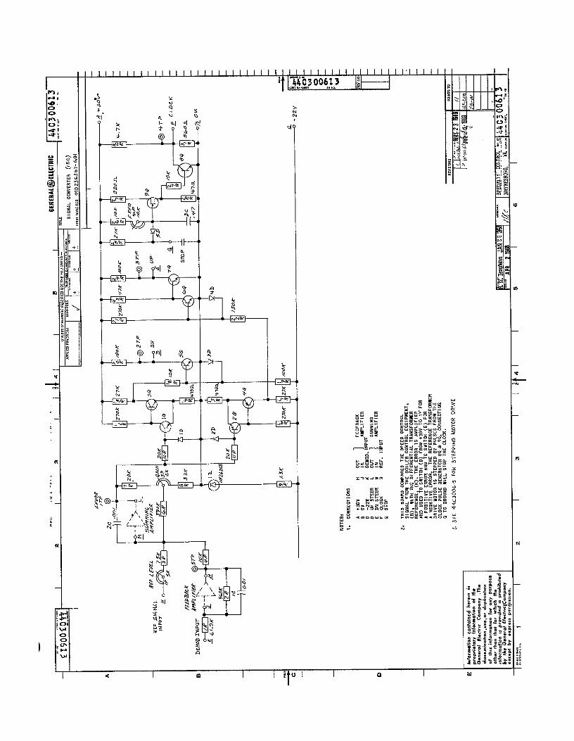
2. SLOW REFERENCE SPEED, 2CL. LOC. 0116,: SHUT OFF HI GH PRESSURE OIL SUPPLY OR DISCONNECT SERVO VALVE BEFORE RAI S I NG MANUAL REFERENCE. ACTUATE RAISE PUSHBUTTON AND TIME TRAVEL TO HSS LIGHT INDICATION. TIME SHOULD BE 80-90 SECONDS. A CLOCK PERIOD OF 40 MILL I SECONDS CAN BE MEASURED AT CLOCK TP.
3. FAST REFERENCE SPEED. 2CL. LOC. 0116: ACTUATE LOWER FAST PUSHBUTTON AND TIME MOTOR TRAVEL FROM HSS LIGHT TO LSS LIGHT. IT SHOULD BE 8 TO 10 SECONDS. A CLOCK PERIOD OF 4.17 MILLISECONDS CAN BE MEASURED AT CLOCK TP WHILE LOWER FAST PUSHBUTTON IS ACTUATED.
4. BIAS AND GAIN, MANUAL REFERENCE, 2LVG, LOC. 0113: DISCONNECT K OF 2LVG. RAISE MANUAL REFERENCE FROM LSS AND BACK I NT0 I T AT SLOW RATE WI TH LOWER PUSHBUTTON. ADJUST MANUAL BI AS FOR 0.000 VOLTS AT OUTPUT TP, 0113. RAI SE TO HSS AT SLOW RATE AND ADJUST MANUAL GAIN FOR OUTPUT VOLTAGE AT TP 0113 AS SPECI F I ED BY AL I GNMENT D I AGRAM.
IX. AUTOSPEED REFERENCE (STAND-STILL CHECK) 1. SET-UP; AUTO REFERENCE CAN BE RUN TO HSS BY JUMPI NC;
T31 TO T32 AND TO LSS BY JUMPI NG T31 TO T33. THE EXTERNAL LEAD FROM THE BOILER CONTROLLER SHOULD BE DISCONNECTED FIRST, HOWEVER.
2. HSS, iSS 2SC, LOC. 0125: WITH AUTO REFERENCE AT LSS, JUMPER T31 TO T32 AND TIME TRAVEL TO HSS. TRAVEL TI ME SHOULD BE ADJUSTED TO 40 SECONDS USING FREQUENCY POTENTIOMETER ON 2SC.
4
52 ‘EVISION
- *PPRD”*LS COMV & CONTROL
7-X 64 ---"':,"d: 5 19%
-DEVI';ES aPJl,- 44A30 1479 LOCATION CON, ON SHEkT 5 SHND 4
FF.BV3.WF <2.(18, I
CJCJE lDLNl I PRINTED I N ” l A
// W-DF~
FG-vd
‘RINTS T
1 44A30 1479
ALIGNMENT INSTRUCTIONS
6 ELECTRON1 C FEED PUMP TURBINE CONTROL
:“NI ON MlELl -OFlffSTAq T- ,,,Fq ,33@, & ,a I 4
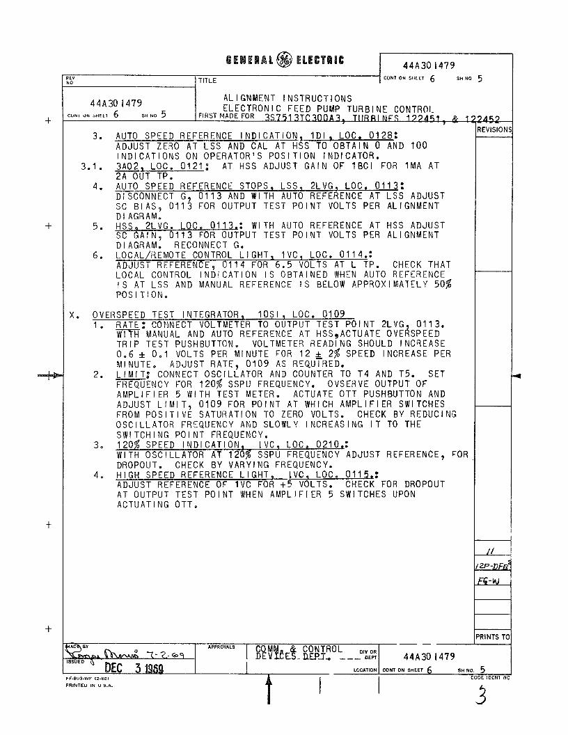
3. AUTO SPEED REFERENCE INDICATION, lDI, LOC. 0128: ADJUST ZERO AT ~ss AND CAL AT HSS TO OBTAIN 0 AND 100 INDICATIONS ON OPERATOR’S POSITION INDICATOR.
3*1. 3A02, LOC. 0121: AT HSS ADJUST GAI N OF 1 BCI FOR 1 MA AT 2A OUT TP.
4, AUTO SPEED REFERENCE STOPS, LSS, 2LVG, LOC, 0113: DISCONNECT G, 0113 AND WITH AUTO REFERENCE AT LSS ADJUST SC BIAS, 0113 FOR OUTPUT TEST POINT VOLTS PER ALIGNMENT DIAGRAM:
5. Hss, 2LVGq LOC. 0113.: WITH AUTO REFERENCE AT HSS ADJUST SC GAIN. 0113 FOR OUTPUT TEST POINT VOLTS PER ALIGNMENT D I AGRAM: RECONNECT G.
6. LOCAL/REMOTE CONTROL LIGHT, IVC, LOG. 0114.: ADJUST REFERENCE, 0114 FOR 6.5 VOLTS AT L TP. CHECK THAT LOCAL CONTROL INDICATION IS OBTAINED WHEN AUTO REFERENCE IS AT LSS AND MANUAL REFERENCE IS BELOW APPROXIMATELY 50% POSITION.
x. OVERSPEED TEST INTEGRATOR, 10Sl, LOC. 0109 1. RATE: CONNECT VOLTMETER TO OUTPUT TEST POINT 2LVG, 0113,
WITH MANUAL AND AUTO REFERENCE AT HSS,ACTUATE OVERSPEED TR I P TEST PUSHBUTTON e VOLTMETER READING SHOULD INCREASE 0.6 f 001 VOLTS PER MINUTE FOR 12 & 2% SPEED INCREASE PER Ml NUTE, ADJUST RATE, 0109 AS REQUIRED.
2. L I Ml T.” CONNECT OSCILLATOR AND COUNTER TO T4 AND T5. SET FREQUENCY FOR 120% SSPU FREQUENCY. OVSERVE OUTPUT OF AMPLI FI ER 5 WI TH TEST METER. ACTUATE OTT PUSHBUTTON AND ADJUST LIMIT, 0109 FOR POINT AT WHICH AMPLIFIER SWITCHES FROM POS I TI VE SATURATI ON TO ZERO VOLTS. CHECK BY REDUCING OSCILLATOR FREQUENCY AND SLOWLY INCREASING IT TO THE SWITCHING POINT FREQUENCY.
3. 120% SPEED INDICATION, IVC, LOC. 0210.: WITH OSCILLATOR AT 120s SSPU FREQUENCY ADJUST REFERENCE, FOR DROPOUT. CHECK BY VARYING FREQUENCY.
4, HIGH SPEED REFERENCE LIGHT, LVC, LOC. 0115.: ADJUST REFERENCE OF 1VC FOR +5 VOLTS. CHECK FOR DROPOUT AT OUTPUT TEST POINT WHEN AMPLIFIER 5 SWITCHES UPON ACTUATING OTT,
?4-5& lEVISION
RINTS TI

+
-I-
‘E” In i TITLE CONT ON SHEET FNL. SHNO 6 I . ,
44A30 1479 CONS ON SHEET FNL SHNO 6
ALIGNMENT INSTRUCTIONS ELECTRON1 C FEED PUMP TURBINE CONTROL
FIRST MADE FOR 3S7513TC300A3, TURBI NES 122451 & 122~
Xl l STOP VALVE POSITION INDICATOR, LDI. LOC. 0102, WITH STOP VALVE FULLY CLOSED ADJUST DIFF. TRANS. NULL FOR -3 VOLTS AT OUT TP AND METER ZERO FOR 0 POSITION. ADJUST CAL. FOR 100% WITH VALVE FULL OPEN.
XI I .PUG POWER SUPPLY 1. INVERTER ADJUSTMENT: WITH THE TURBINE RUNNING AT 70 TO
100% RATED SPEED ADJUST THE PMG INVERTER (BOTTOM FRONT) FOR 38 VOLTS MEASURED AT D+ AND E-, lSR, LOC. 0310.
2. INDIVIDUAL POWER SUPPLIES: ADJUST THE I NDI VI DUAL POWER SUPPLY LEVELS UNTI L THE LINE SUPPLIES ARE CARRYING ONLY 0.1 AMPS AND THE PPG SUPPL I ES ARE CARRYING THE REST OF THE LOAD. WHILE NOTING THAT THIS CONDITION IS MAINTAINED MAKE FINAL VOLTAGE LEVEL AND METER CALIBRATION ADJUST- MENTS. ALSO TEST AND SET METER RELAY ALARMS AT 95 AND 105%
SUPPLY LOCATION TEST POINTS
PMC;. LINE
+30 0310 0308 BUS BARS
-22 0318 0316 BUS BARS
24 0326 0324 PMG-+F’, 03280 -G, 0326 LINE +F, 0323; -G, 0324
SEE LEVER DI AGRAM FOR RUNNING CHECKS OF SPEED REGULATION.
HP STOP VALVE POSITION INDICATOR lDI, LOC. 0104. SAME AS Xl.
52 !EVISION:
4
‘RINTS TC

+
+
GEIEAAL@$ ELECTCBJC 44A302609
TITLE CON, ON SHEET SH NO
CLOCK (2CL)
FIRST MADE FOR 3.575 \ 3TC300
- ALL RES \ sToRs
THIS RELAXATION OSCILLATOR DEPENDS UPON THE CHARACTERISTICS OF PROGRAMMABLE UNIJ UNCTION TRANSI STOR 2Q FOR ITS OPERATI ON. 1 C CHARGES UNTIL ANODE VOLTAGE EXCEEDS GATE VOLTAGE BY A DloDE DROP AT WHICH TIME 2Q TURNS ON DISCHARGING 1C THROUGH 4R TURNING ON 1Q. AFTER DISCHARGE,THE ANODE CURRENS FROM 8R-11 R IS LESS THAN HOLDING CURRENT OF 2Q, WHI CH TURNS OFF AND THE CAPACITOR AGAIN CHARGES.
SWITCH T
CLOSED 37-44 MSEC.
OPEN I
4.17-4.6 MSEC.
OUTPUT WAVE FO R M
I,,::_,-sK
PI 1t+ 30 -T-o sop SEC,
EVISION:
‘RINTS T
1 I
n 2.0
I?
2 I
r..T
L---
J
I.’
I
I
CO
NN
ECTI
ON
S A
+3
ov
N,K
IN
PUT
B
OJ
L SE
C NO
-iE
2
c -2
rfl
I M
NOTE
S:
7.
IN
NORM
AL
OPE
RATL
ON
THE
RELA
Y IS
EN
E~IZ
ED.
IT
CAN
DE
ADJU
STED
TO
DR
OPOU
T ON
’ El
THER
IN
CREA
SING
OR
DE
CREA
SlNQ
SI
GNAL
S BE
TWEE
N PL
US
AND
WIN
US
10
VOLT
S.
2.
DROP
OUT
ON
INFI
UT
JUM
PER
INOR
EASI
NC
SIGN
AL
RELK
l’p
DEOR
EASl
NQ
SlQN
AL
L ;I:
3.
RELA
Y CO
NTAC
TS
RATE
D 21
1,
PEVD
O.
FRCE
PLAT
E
t
DROP
OUt
- N>
L -
i I,
$ E, I ;
,
- . A
5 - . .
PO,
4 C
. . D
E
OU
TPU
T N
OTE
S:
1.
CO
NN
ECT,
ON
3
i +3
ov
GROU
ND
DIF
FER
ENTI
AL
s -2
2v
TRAN
SFO
RM
ER
OU
TPU
T

t- lO
OK
1 E-
T-
R ‘+
7X 1
-22
Y
SPEO
IFIO
ATIO
NS
1.
OFF
SET
OU
RAE
Nf 1
0-g
AM
P.
2.
OFF
SET
VOLT
AGE
0%
TO 5
00
c *
o.zu
v 60
%
.*w
*
.,M”
CO
NN
eCtlo
NS
A
r3ov
0
OV
c -2
2 v
D
INPU
T E
O
UTP
UT
3.
INPU
T IM
PEN
OAN
OE I
1OO
KQ U
IN.
4,
ALLO
YAG
LE LO
AD C
APlO
ttlN
CE
5.
OU
TPU
T VO
LtllG
E tt0
. ,
1OO
Opf
6.
OU
TPU
T C
UR
REN
T t,O
m
a 7.
G
AIN
: DC
- 10
’ M
IN.
&IAC
TEFI
ISTI
~:
- 50
00
M,N
IT
10
0 O
PS
BR
EA
K FR
EGU
ENO
Y - 25
0 W
S 20
db
PE
R C
EOlC
E TO
VOLT
S.

I
NOTE
S I.
THIS
Cl
RCUl
T IS
CO
NPOS
ED
OF
3 BO
ARDS
CONN
ECTl
ONS
BOAR
D 1
BOAR
D 2
BOAR
D 3
i &N
O =U
ND
MET
ER
RELA
Y GR
OUND
c
-22”
-2
2v
-22v
D
F O
F x2
E
FEED
BACK
?
:: f:
F FE
EDBA
CK
0 O
F Xl
t
:: $$
E
OF
#r
0 FE
EDBA
CK
OUTP
UT
“J
FEED
nACK
OU
TPUT
-2
2 a
OUTP
UT
: -2
2 &
OUTP
UT
Ii
0 O
F #I
@ER
ATIO
N:
r
ADJU
STM
ENT:
1.0
PREL
IMIN
ARY
1P
NONE
RE
PUlR
ED
IOlP
EX
TREM
E CC
Y 20
1P
NONE
RE
PUlR
ED
2x
MID
RA
NGE
(DO
NO
T FO
RCE)
2.0
ADJU
ST
2X
FOR
OSO
ILLA
TIO
N AT
BK
HZ.
3.0
ADJU
ST
101P
FO
R 0.
8 VO
LTS
104T
P (+
) TO
,O
BTPt
-) NO
TE
VOLT
AGE
102T
P TO
10
5TP
SHOU
LD
NOT
EXCE
ED
t .0
40
VOLT
S.
4.0
ADJU
ST
,P
FOR
OUTP
UT
OF
6YO
LTS
RMS
AT
TEST
PO
INTS
ON
BO
ARD
3.
5.0
&M;;T
20
1P
TO
CALI
BRAT
E EX
TERN
AL
1 M
A OU
TPUT

‘HS
UN,
*HOO
S e, A
S ‘X
OYdd
Y ON
V 593
131
‘VYI
1 01
1 :l”d
l”O
I) os
1-L
:33v
1101
\ l”d
Nl
“H
055-
O
:33&
i ln
dNl
‘1
I I
I

OPER
ATOR
’S
CONT
ROL
PUSH
WTT
CNS
LOSE
R FA
ST
LOW
ER
RAIS
E RA
’SE
FAST
NC
SPEE
D SI
GNAL
OP
ENS
CLAM
P
,SPE
EC
SET
POIN
T
LOW
“A
L”!
GAT
E
!&--~
pcs,
T,cN
,N
c,C
ATcR
LP
ST
OP
YALY
E
I PO
SITI
ON
INCI
CATC
R I I
.----
I I SO
ILER
CO
NTRO
LLER
’
WrC
R CO
NTRO
L
REF
S14
NA
l (
;
I
6 0 -2
2v
NOTE
S:
1.
CONN
ECT1
ON
S
A +3
ov
s 0”
c
-22”
D
UP
STEE
R E
ON
STEE
R F
CLOC
K 0
STO
P
2.
0 TO
GR
OUND
SI
LL
STO
P TH
E CL
OCK.
3.
SE
E 4
4C30
0615
FO
R ST
EPPI
NG
M
OTO
R D
RIV
E

1 1
f/R /
M)
(28
OUT
) ,7
-P
@
IO.4
IO
K
r---
---
,BOl
LER
CONT
RCL
1 ,R
EF.
POSI
TION
I I
lo
MA.
L!
iS
INPU
T FR
OM
E.
H.C,
11
MA.
HS
S I
--1
I I
NO
TES:
1.
1.
4 IN
PUT
OU
TPU
T -,o
v-
0”
+tlW
+5
v B
IAS
RAN
GE A
PPR
OX.
I” -1
2”AT
IN
PUT
2.
2A
IN
OUT
0 -5
!,v
3 C
ON
NEC
TIO
NS
A t3
ov
E IN
PUT
FRO
M
WJIL
~R
CON-
LRO
‘ B
GRo
”No
F AM
PLIF
IED
BO
ILER
CO
NTR
OL
SIG
NAL
c
-22v
G
EH
C
REF
D
BO
lLLR
C
ON
TRO
L G
NTJ
N
REF
?0S
1not
i O
UTP
UT
TO
BOIL
ER C
ON
TRO
L

(W
_ (-2
2v.)
@
ckLo
or)
@I-
T I
- I
- III
-
I -
83%
K,?
K
,


%L#
LO
IS
ONY
2X
H3W
38
a,
“On
SIZO
3,
dHVX
3 ‘(I
8 ‘3
-d
3Hl
SIN3
S3Nd
3LI
HOIH
M
3W”D
S 3H
L LlV
lN
YO
N,
ONl
W3d
dV
SU38
WnN
3”
l A8
NA
OHS
S,
WW
O8
l,“OU
,O
a31N
,Bd
3Hl
Jo
NOllV
307
3HI
‘k
313t
M35
13
NlOH
S IO
N SN
0,13
3NNO
O
WNO
,l,OPI
I 3”
” SB
I,d,,d
WV
,YNO
,lVU3
dO
7-I”
‘E
2880
0EW
t
ESLL
OEO
PP
8LtO
OEv
rC
S980
0EO
Pt
9V90
FsKI
SLSE
5v9O
Ex+E
ISLS
F
,b03
-8LL
SLFO
CV
LVLO
FjHE
LSLS
E
WYO
EdHE
IS
LSF
EV9O
EsKL
SLSE
IVSO
EalE
ISLS
E
LVVO
FdHE
LSLS
F
IVGO
F,HF
KiLS
E
EVOO
EdHE
tSLS
E ZV
OO
EdW
EGLS
F
‘ON
u3au
o
,BNV
d L1
313F
)
3*1n
o ww
x *d
ata
,BNV
d AV
l3tl
-,3NV
d L1
313N
13NV
d U3
1311
13NV
d 80
1s
153n
-,3NV
d 13
111.
4
LoS-
L2aL
mtP
kowL
Sst8
Saw
LOD-
Z‘FS
EZO
PP
100-
SvF9
E2ai
-P
t03-
sast
afaw
Log-
oLE9
62aw
wb-s
vE9E
Zabb
ZOD-
YLE9
EZaP
P
L090
000P
k oc
soo~
a6c
I 6%
00E(
ICP
SL90
0E3b
t
8bY
bOEO
PC
6990
0F3P
t
29ZO
OFV
1P
1 L9
00EO
Pk
0190
0E3P
t
OLsW
fat~
69
6ooF
abt
2b2O
OEY
w
b921
)OEV
PP
2190
0E3P
1,
6090
0F3~
r
CPZO
OEVP
P
QO
blO
EYbb
609z
oEVP
r
2291
0E3P
I
Y’JA
ll(i
YoIv
lrla3
Y
E aw
oa
‘050
‘Z
HXE
Z W
OB
‘OS0
‘Z
HXS
3LV3
3”
WA
101
‘d&!
n011
1v’6
103
33Vl
lDA
z#
awoa
w3
u S3
iu3s
BAll(
l Ll
Oul
ll 0N
lddi
U.S
131Y
3ANO
O
1VNO
IS
L131
,,,dl
V OA
IBS
NOIV
8331
N,
(133
6513
10
1 aw
oa
*aso
ni
x
L13I
,l,dl
V ,Y
NOllV
83dO
r#
*afl
‘03t
l s3
I t
13s
L137
3hO
"D~
3,YD
3f
nVA
"07
WNP
,S
L13L
llANO
O
33Vl
lOA
'D31
d
801V
3,O
Nl
uoLo
3na
au08
3a
ola
NOllV
lfl53Y
g
NOllV
SN3d
,,103
awoS
n3
073
l”dl”0
BO
lVNV
I
ZUVf
3v
Ia
w13
3,11
1 ,o
a1*s
awoa
lm
3m
a3~N
ki
IS,,
‘NSV
‘a
ns
PNV
owoa
11
”081
0 03
1NlU
d
69 L
LO
EOVb
WVW
VIO
N011
33NN
00

SG=
SHL=
..?- 3
FOR
S
CP
d/N
VER
T-‘?
@
i%ZR
OL)
f’=
W4S
? S-
OPP
LY
W/fH
P
M5
SOO
ECE
-----c
------
---
---__
-__-
---
3306
ec
oe
0310
00
1,
SE
RIE
S R
EG.
ma.
*,
\REL
.
lnlo
rmat
ion
rant
&ted
he
rein
is
~r
orrri
.t.xr
in
lorm
ctia
n of
Ih
.
sh
J “r,
, -7
4 =
I-----
‘: --_
_ ---
-_---
_-
-__-
’
&
-
:” A
JND
JCAT
ES M
OU
NTE
D O
N C
ON
TPO
L P
AN
EL
0220
KS
%
SP
EE
D
II6
/ +-
0 0-
I MA ;
A- TA
CH
*
---F
-E
l$S
C
05tl
LLAl
-OR
B c
AMPL
IFIE
R

I 2
I 3
I I
5 I
GEN
ERAL
@EL
ECTR
IC
"NES
S OTH
ERW
ISE
SPEC
lFlE
D "S
E TW
E FOLL
OWlN
G -
TITL
E 1o
LI”A
”nl
o* “A
c”11
1m
mxc
*,m*,
ELEH
ENTA
RV
DIAG
RAM
EL
ECTR
ON
IC FE
EDPU
MP T
”RB,
NE
CO
NTR
OL
. . . . .
. . . .
._.._
..._.
.. ___
_ 12
2451
&
1224
52
CO
NEM
AUG
H
NO
. 1
MAN
UAL
R
EFER
ENC
E I
r
I’- ‘-I
EN
D
+ -;r
v M
AN
LlA
L 00
04
SPEE
D REFE
RENC
E
ov
-7 v
I
41s
MAN
. R
EF
SH 5

REF
EREN
CE
Law
V
ALU
E
’ R
EF.
LOW
VA
L:E
SAT
E & O
YER
SPEE
O TE
ST I
NT.
f G
A’
.A 01
09
OVE
RSP
EED
TE
ST
INTE
GR
ATO
R
AMPL
W&
No7
C
ON
TRO
LLIN
G
AT
t 10
~ D
VE
AS
PE
ED
50
7 R
Lf.
-5””
20%
S
PE
EI: ;
J
-N
SH4
AUTO
R
EP
42
1 l-5
5 0”
H
3S
-5’
B--L
-D
BIA
S
503
W-l
E
i I
I C3O
V 0”
LO
SH.7
t3
0”
OJ
-22”
zo
ol &
I( (z
oz
I I
IY
Tb
At
c---c
2.:
-.‘ ov
+3
w
-22v
ipE
ED
ilG
NAL
.6
DR
OPO
UT=
LO
CAL
PI
CKU
P =
REM
OTE
It i

1fld
Nl
033d
S
13N
NVH
> a3
3dS
,C,W
,N03
35
I
f-4
IOZ
H
so3 ’
i’ so
20
S’H
S-
SO
3110
1 03
3dF
A0
AOEi
IOZ
ooz
I I ;--
. 3
a v
I i3
~~Vi
i3
a33d
s M
VWltl
d
- < - -m

.“. -
SW.6
I ‘4

d I 4

r - - - .
L
Hi
- - - - .
7
w C

E _.
z C . . D
204
, ‘1
I ;
I /
I -
I I
- I
-
6 NOTE
: FO
R *
CONN
ECTI
ONS
TO
MR*
S SE
E PO
YER
SUPP
LY
Cl
RCUI
TS
SH
EETS
293
.
2.
5RIP
%
I
- _I
l--
----
,MH
SS
r L N
, 51
: ICO
-J
.
-
---l REM
, .-_
I

r --- “! 1

TOY
-- -- g
i ?&
g$
-- w
- 6-
r,”
%-
REV
HO
-
--

f
$ r-

IIIlllllllllllll~L~ II Ill1 I III IIIlrlI III1 ll l l l l l l l l l II I’“&” 3016&9 I;1 ~rwmm Wm.
t
.,- I
4 I m I I

2 & -
-
I I I.--- T. u $G _---i
I I I
1 ~a
4 ‘I
I
-r----
---i
J 11
bt

EHC
AL
IGN
MEN
T D
IAG
RAM
--
- -_
,/Y,..”
-8.
Y.a
, 2
Id31
I
4 I
6 1
1 its
i 7
I 6
I is
i 10

[
A
B
3 ; 3 E
F +
::
!
,,., ,“
., I”o
I”Y.,
1 2
i $3
; 4
I E
l I
iif51
7
a i
iIS/
10

1111111111111111111,,,I,II,l,,,,,,,,,,,l,ll),l,,,,l,,l,,,,,,,,,,,, 11 Y r
2: zz -
m G .- -
m
-
b
ID c -
-
P
*
-
m s -
N
-
Ii u
.-

--FFr7--------- - -----------=-
i \
\ \ \ \ ,

Illlllllllllil~~~,,,,,,,,,,~,,,,,,,,, ,,I,(,,,
?i 1

6-70(500)
COMMUNICATION AND CONTROL DEVICES DEPARTMENT
WAYNESBORO, ‘$A.