electrochemical decolourization of reactive black 5 in an
TRANSCRIPT

doi:10.5599/jese.164 145
J. Electrochem. Sci. Eng. 5(2) (2015) 145-156, doi: 10.5599/jese.164
Open Access : : ISSN 1847-9286
www.jESE-online.org
Original scientific paper
Electrochemical decolourization of Reactive Black 5 in an undivided cell using Ti and graphite anodes: Effect of polypyrrole coating on anodes
Snehal A. Popli and Upendra D. Patel*,
Civil Engineering Department, C. S. Patel Institute of Technology, Charotar University of Science & Technology, Gujarat, India *Civil Engineering Department, Faculty of Technology & Engineering, The M. S. University of Baroda, Gujarat, India
Corresponding Author: [email protected]; Tel: +91-9687961022
Received: April 2, 2015; Revised:August 5, 2015; Published: August 26, 2015
Abstract Electrochemical decolourization of azo dye Reactive Black 5 (RB5) was studied using Ti, graphite, and polypyrrole coated Ti (PPy-SLS-Ti) and graphite (PPy-SLS-G) anodes in the presence of sodium chloride as an electrolyte to investigate the effect of polypyrrol coating. The colour removal efficiencies were 52.6 %, 96.3 %, 51.6 %, and 41.0 % respectively for above anodes, at the end of 90 minutes of electrolysis at current density of 5 mA cm-2. The presence of polypyrrol coating resulted in lower decolourization than that in the absence of coating. The major characteristic absorption peaks of RB5 at 595 and 312 nm present initially, decreased consistently and no new peak emerged during electrolysis using uncoated Ti and graphite anodes which indicated direct and/or indirect oxidation playing major role in decolourization. In case of PPy-SLS-Ti and PPy-SLS-G anodes, a new peak at 254 nm emerged distinctly which was determined to be vinylsulfone (VS), an amine. Generation and accumulation of VS suggested that oxidation of RB5 was suppressed while reduction at cathode played important role in RB5 decolourization using PPy coated anodes. The results obtained in the present study may lead to development of anodes for undivided cell, on which, the extent of oxidation may be controlled by a suitable coating such as PPy.
Keywords Electrochemical oxidation; Azo dye; Vinyl sulfone; Polypyrrol coating
Introduction
Dye wastewater is an environmental concern due to its huge quantity, variable nature, low
biodegradability, chemical composition, and toxicity to aquatic life [1]. In the textile industry, 60 %
brought to you by COREView metadata, citation and similar papers at core.ac.uk

J. Electrochem. Sci. Eng. 5(2) (2015) 145-156 ELECTROCHEMICAL DECOLOURIZATION USING Ti & GRAPHITE ANODES
146
of the dyes used are azo dyes, in which the azo (–N=N–) group is connected to an aromatic
compounds forming a chromophoric group responsible to impart a characteristic colour to the
dye. Reactive dyes are widely used due to their relatively easy application in the dyeing
process [2]. For the removal of dyes from wastewater, different techniques such as chemical
precipitation, chemical oxidation, adsorption, and biological processes have been developed [3].
The electrochemical technologies (electrochemical oxidation (EO), electrochemical reduction (ER),
electrocoagulation (EC), indirect electrooxidation with strong oxidants, and emerging photo-
assisted electrochemical treatments for treating dye wastewaters have been proposed [4]. The
application of these technologies is benefiting from advantages such as versatility, environmental
compatibility, and potential cost effectiveness. For electrochemical treatment of industrial
wastewaters, direct and indirect EO processes are widely used. In a direct EO process, pollutants
are first absorbed on the anode surface and then destroyed by the electron transfer reaction.
Different anode materials, such as dimensionally stable anodes, noble metals, carbon-based
anodes, metal oxides, and boron-doped diamond electrodes have been explored for degradation
of dyes. In an indirect EO process, strong oxidants, such as ozone, chlorine, hypochlorite, and
hydroxyl free radicals are generated electrochemically which, in turn, destroy the pollutants by the
oxidation reactions. All of the oxidants are generated in situ and are utilized immediately [5-7].
Graphite and metal oxide coated Ti electrodes have been shown to be able to decolourize
various dyes [8-11]. Metal oxides can be coated directly on a substrate or through a conducting
polymer already coated on the anode surface. Conducting polymers are permeable to
electroactive species and they are easy to coat on various substrates. Conducting polymers with
porous structures and high surface areas, such as polyaniline and polypyrole, are usually employed
as matrix to incorporate noble metal catalysts for the electro-oxidation of small molecules such as
hydrogen, methanol and formic acid [12,13].
Polypyrrole (PPy) is a conducting polymer and can be formed chemically or electrochemically
through oxidative polymerization of pyrrole, the final form of PPy is a long conjugated backbone as
shown in Figure 1. Electrochemical synthesis is the most common method as it is simpler, quick
and perfectly controllable [10].
Figure 1. Chemical structure of Polypyrrole
The electrical and physical properties of the polymeric films are considerably influenced by the
conditions under which they are prepared, such as the electrochemical method of polymerization,
concentration of monomer and doping agent and other synthesis conditions. In its neutral state
the polymer is not conducting and only becomes conducting when it is oxidized and have a
conductivity of 10-3 to 102 (Ω cm)-1 [14-16]. Use of electrodes coated with metal-nanoparticles-
incorporated PPy as cathodes for electrochemical reduction (ER) reactions have been reported.
For example, Sun et al. [17] demonstrated use of Pd-PPy-CTAB-Ni foam cathode in a divided cell
for ER of 2,4-dichlorophenol (2 4-DCP). 2,4-DCP was dechlorinated to phenol and the cathode
could be reused for 10 dechlorination cycles. Similarly, ER of nitrate and nitrite on PPy-Cu cathode

S. A. Popli et al. J. Electrochem. Sci. Eng. 5(2) (2015) 145-156
doi:10.5599/jese.164 147
in a divided cell is reported by Nguyen et al. [18]. However, behaviour of PPy coated electrodes as
anode has not been studied to the best of our knowledge. The main aim of the present study was
to compare the performance of Ti, Graphite, and PPy coated Ti (PPy-SLS-Ti) and graphite
(PPy-SLS-G) as anodes for electrochemical decolourization of RB5 in an undivided cell to
investigate the influence of PPy film on the extent and mode of decolourization.
Materials and Methods
Chemicals
Experimental chemicals including sulphuric acid (H2SO4, 98 %), sodium lauryl sulphate (SLS,
NaC12H25SO4), sodium carbonate (Na2CO3), sodium sulphate (Na2SO4), sodium chloride (NaCl), and
oxalic acid (H2C2O4 x 2H2O) were of analytical standard and supplied by S D Fine Chem Ltd.,
Mumbai. Pyrrole (C4H5N) was obtained from Spectrochem Pvt. Ltd. Ahmedabad. Titanium material
grade 2 (300×450×0.5 mm) was supplied by Shree Ambe Engineering, Vadodara. In all the
experiments, the size of anodes (Ti, graphite, PPy-SLS-Ti, or PPy-SLS-G) was 4×3 cm. Two stainless
steel (SS) plates of the same size were used as cathodes. Reactive Black 5 (RB5) dye was supplied
by a local dye industry. It was used without further purification. All solutions were prepared using
distilled water.
Table 1. General characteristics of Reactive Black 5 (RB 5) [19, 20].
Parameters Value
Molecular formula C26H21N5Na4O19S6
Molecular weight 991.82 g/mol
max 595 nm
Molecular structure
Some common information about RB5 is given in Table 1. A calibration plot of absorbance at
595 nm versus various RB5 concentrations was constructed and found to be linear within the
concentration range of interest with R2 value of 0.9985.
Preparation of PPy-coated Ti and graphite electrodes
Before PPy coating, Ti plate was pre-treated first. Ti plate was placed in 0.3 mol L-1 Na2CO3
solution at 90 oC for 30 min to remove surface grease. Then it was placed in 0.1 mol L-1 boiling
oxalic acid for 30 min to remove surface oxides. Finally, it was rinsed thoroughly with distilled
water and soaked in ethanol for later use. During electropolymerization of PPy-SLS composite film,
the Ti plate was used as anode, and the SS plate was used as cathode. PPy-SLS film was formed on
the surface of Ti plate by electrodepositing in a 250 mL mixed solution containing 0.3 mol L-1
H2SO4, 0.1 mol L-1 distilled pyrrole (Py), and 1.0 g L-1 SLS for 45 min with the electrodeposition
current of 60 mA. The mixed solution was deoxygenated by Ar for 5 min before the commen-
cement of electrodeposition. PPy-SLS/graphite plate was prepared similarly by taking graphite
J. Electrochem. Sci. Eng. 5(2) (2015) 145-156 ELECTROCHEMICAL DECOLOURIZATION USING Ti & GRAPHITE ANODES
148
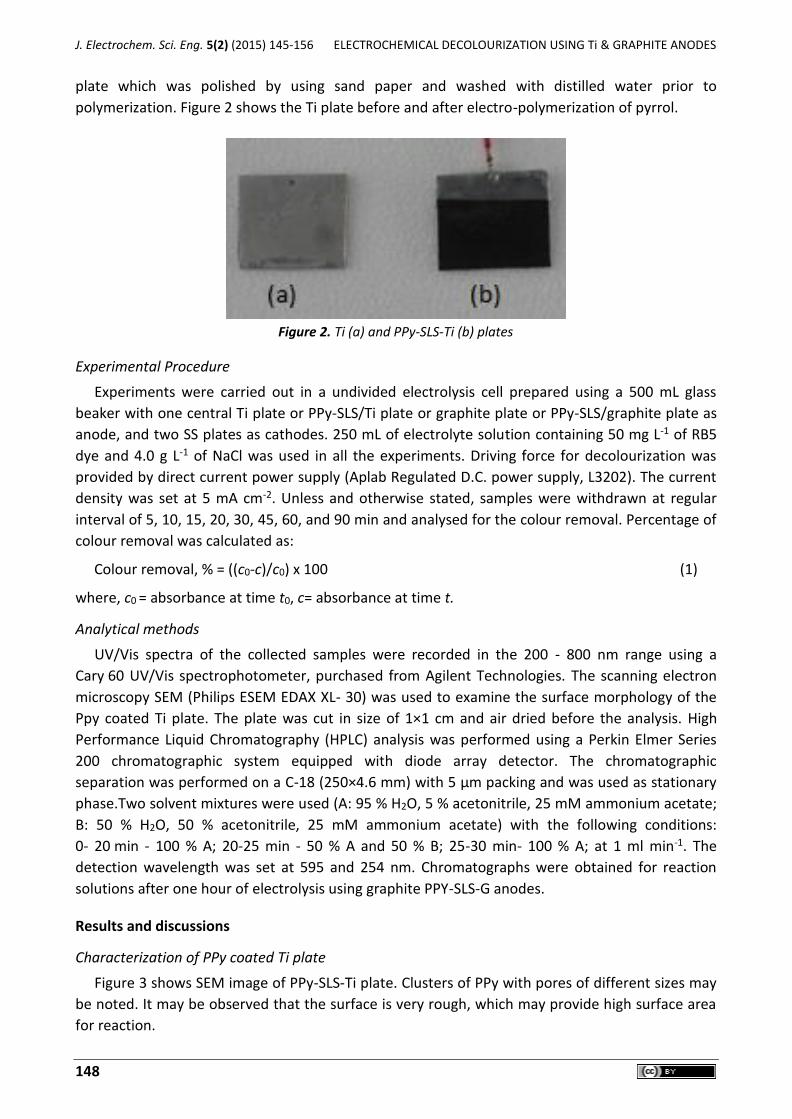
plate which was polished by using sand paper and washed with distilled water prior to
polymerization. Figure 2 shows the Ti plate before and after electro-polymerization of pyrrol.
Figure 2. Ti (a) and PPy-SLS-Ti (b) plates
Experimental Procedure
Experiments were carried out in a undivided electrolysis cell prepared using a 500 mL glass
beaker with one central Ti plate or PPy-SLS/Ti plate or graphite plate or PPy-SLS/graphite plate as
anode, and two SS plates as cathodes. 250 mL of electrolyte solution containing 50 mg L-1 of RB5
dye and 4.0 g L-1 of NaCl was used in all the experiments. Driving force for decolourization was
provided by direct current power supply (Aplab Regulated D.C. power supply, L3202). The current
density was set at 5 mA cm-2. Unless and otherwise stated, samples were withdrawn at regular
interval of 5, 10, 15, 20, 30, 45, 60, and 90 min and analysed for the colour removal. Percentage of
colour removal was calculated as:
Colour removal, % = ((c0-c)/c0) x 100 (1)
where, c0 = absorbance at time t0, c= absorbance at time t.
Analytical methods
UV/Vis spectra of the collected samples were recorded in the 200 - 800 nm range using a
Cary 60 UV/Vis spectrophotometer, purchased from Agilent Technologies. The scanning electron
microscopy SEM (Philips ESEM EDAX XL- 30) was used to examine the surface morphology of the
Ppy coated Ti plate. The plate was cut in size of 1×1 cm and air dried before the analysis. High
Performance Liquid Chromatography (HPLC) analysis was performed using a Perkin Elmer Series
200 chromatographic system equipped with diode array detector. The chromatographic
separation was performed on a C-18 (250×4.6 mm) with 5 µm packing and was used as stationary
phase.Two solvent mixtures were used (A: 95 % H2O, 5 % acetonitrile, 25 mM ammonium acetate;
B: 50 % H2O, 50 % acetonitrile, 25 mM ammonium acetate) with the following conditions:
0- 20 min - 100 % A; 20-25 min - 50 % A and 50 % B; 25-30 min- 100 % A; at 1 ml min-1. The
detection wavelength was set at 595 and 254 nm. Chromatographs were obtained for reaction
solutions after one hour of electrolysis using graphite PPY-SLS-G anodes.
Results and discussions
Characterization of PPy coated Ti plate
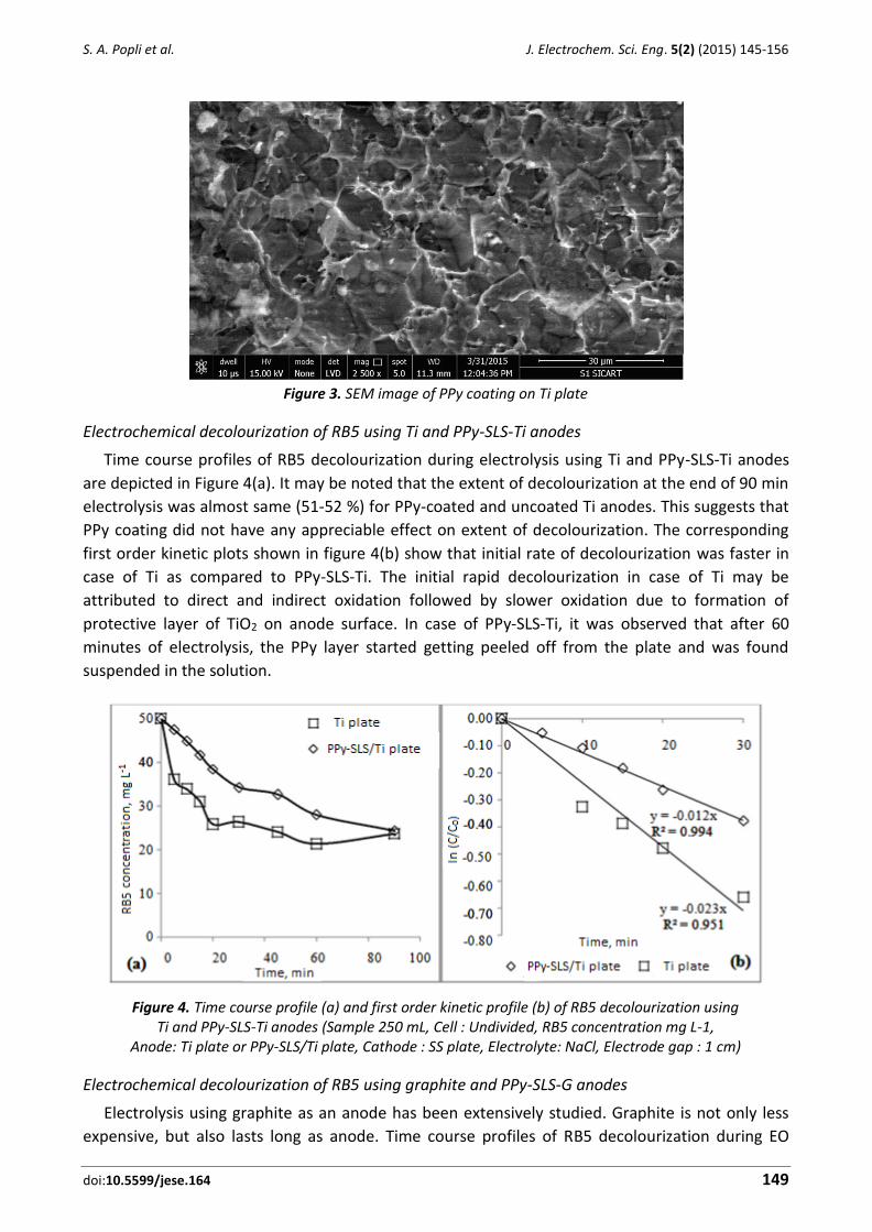
Figure 3 shows SEM image of PPy-SLS-Ti plate. Clusters of PPy with pores of different sizes may
be noted. It may be observed that the surface is very rough, which may provide high surface area
for reaction.
S. A. Popli et al. J. Electrochem. Sci. Eng. 5(2) (2015) 145-156
doi:10.5599/jese.164 149
Figure 3. SEM image of PPy coating on Ti plate
Electrochemical decolourization of RB5 using Ti and PPy-SLS-Ti anodes
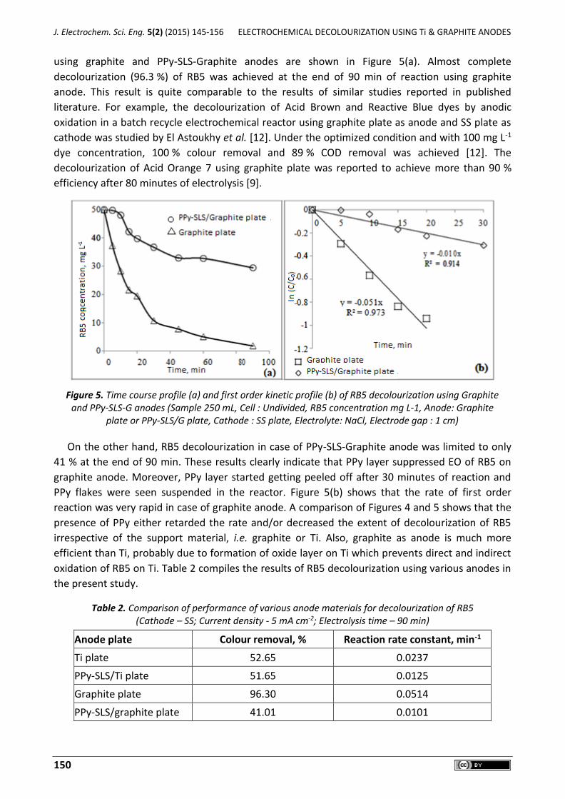
Time course profiles of RB5 decolourization during electrolysis using Ti and PPy-SLS-Ti anodes
are depicted in Figure 4(a). It may be noted that the extent of decolourization at the end of 90 min
electrolysis was almost same (51-52 %) for PPy-coated and uncoated Ti anodes. This suggests that
PPy coating did not have any appreciable effect on extent of decolourization. The corresponding
first order kinetic plots shown in figure 4(b) show that initial rate of decolourization was faster in
case of Ti as compared to PPy-SLS-Ti. The initial rapid decolourization in case of Ti may be
attributed to direct and indirect oxidation followed by slower oxidation due to formation of
protective layer of TiO2 on anode surface. In case of PPy-SLS-Ti, it was observed that after 60
minutes of electrolysis, the PPy layer started getting peeled off from the plate and was found
suspended in the solution.
Figure 4. Time course profile (a) and first order kinetic profile (b) of RB5 decolourization using
Ti and PPy-SLS-Ti anodes (Sample 250 mL, Cell : Undivided, RB5 concentration mg L-1, Anode: Ti plate or PPy-SLS/Ti plate, Cathode : SS plate, Electrolyte: NaCl, Electrode gap : 1 cm)
Electrochemical decolourization of RB5 using graphite and PPy-SLS-G anodes
Electrolysis using graphite as an anode has been extensively studied. Graphite is not only less
expensive, but also lasts long as anode. Time course profiles of RB5 decolourization during EO
J. Electrochem. Sci. Eng. 5(2) (2015) 145-156 ELECTROCHEMICAL DECOLOURIZATION USING Ti & GRAPHITE ANODES
150
using graphite and PPy-SLS-Graphite anodes are shown in Figure 5(a). Almost complete
decolourization (96.3 %) of RB5 was achieved at the end of 90 min of reaction using graphite
anode. This result is quite comparable to the results of similar studies reported in published
literature. For example, the decolourization of Acid Brown and Reactive Blue dyes by anodic
oxidation in a batch recycle electrochemical reactor using graphite plate as anode and SS plate as
cathode was studied by El Astoukhy et al. [12]. Under the optimized condition and with 100 mg L-1
dye concentration, 100 % colour removal and 89 % COD removal was achieved [12]. The
decolourization of Acid Orange 7 using graphite plate was reported to achieve more than 90 %
efficiency after 80 minutes of electrolysis [9].
Figure 5. Time course profile (a) and first order kinetic profile (b) of RB5 decolourization using Graphite
and PPy-SLS-G anodes (Sample 250 mL, Cell : Undivided, RB5 concentration mg L-1, Anode: Graphite plate or PPy-SLS/G plate, Cathode : SS plate, Electrolyte: NaCl, Electrode gap : 1 cm)
On the other hand, RB5 decolourization in case of PPy-SLS-Graphite anode was limited to only
41 % at the end of 90 min. These results clearly indicate that PPy layer suppressed EO of RB5 on
graphite anode. Moreover, PPy layer started getting peeled off after 30 minutes of reaction and
PPy flakes were seen suspended in the reactor. Figure 5(b) shows that the rate of first order
reaction was very rapid in case of graphite anode. A comparison of Figures 4 and 5 shows that the
presence of PPy either retarded the rate and/or decreased the extent of decolourization of RB5
irrespective of the support material, i.e. graphite or Ti. Also, graphite as anode is much more
efficient than Ti, probably due to formation of oxide layer on Ti which prevents direct and indirect
oxidation of RB5 on Ti. Table 2 compiles the results of RB5 decolourization using various anodes in
the present study.
Table 2. Comparison of performance of various anode materials for decolourization of RB5 (Cathode – SS; Current density - 5 mA cm-2; Electrolysis time – 90 min)
Anode plate Colour removal, % Reaction rate constant, min-1
Ti plate 52.65 0.0237
PPy-SLS/Ti plate 51.65 0.0125
Graphite plate 96.30 0.0514
PPy-SLS/graphite plate 41.01 0.0101

S. A. Popli et al. J. Electrochem. Sci. Eng. 5(2) (2015) 145-156
doi:10.5599/jese.164 151
Mechanism of electrochemical decolourization of RB5 at various anodes
The transformation of a dye in an undivided cell may be due to its direct or indirect oxidation or
reduction depending upon the working electrode. On the other hand, in a divided cell, oxidation
occurs in anode compartment, simultaneously with reduction in cathode compartment.. It has
been reported that all peaks of UV/Vis spectrum of a dye consistently decrease with time without
formation of any new peak in case of oxidation in a divided cell. Del Rio et al. [21] studied the
electrochemical oxidation and reduction of Reactive Orange 4 (RO4) using Ti/SnO2-Sb-Pt and SS as
anode and cathode, respectively, and reported that no new peak was generated during the
oxidation of RO4 in the time-dependent UV/Vis spectra. Mendez-Martinez et al. [22] studied the
electrochemical reduction and oxidation pathways of RB5 with Ni-PVC composite cathode and Ni
wire mesh anode in an undivided cell and found that RB5 spectra reduces with time and no new
peaks were formed during the oxidation process. Costa et al. [23] reported decrease in the
absorbance values of peaks during the electrochemical oxidation of Acid Black -210 using boron
doped diamond electrode as an anode. Similarly, Kariyajjanavar et al. [24] reported consistent
decrease in all the peaks and the absence of formation of any new peaks in an undivided cell
during the degradation of Novacron Deep Red C-D (NDRCD) and Novacron Orange C-RN (NOCRN)
reactive azo dyes from aqueous solution using graphite electrode.
On the other hand, reduction of an azo dye is normally associated with formation of a new peak
in UV/Vis spectrum as a result of generation of amine due to cleavage of azo link/s. Del Rio et al.
[25] studied the electrochemical reduction of Reactive Orange 4 (RO4) and reported that the deco-
lourization took place via cleavage of azo bonds and a new peak was formed at 246 nm which was
identified as 2-amine-1,5-napthalenedisulfonic acid as one of the amines. Vidhu and Phillip [26]
studied the catalytic reductive degradation of Methyl Orange by sodium borohydride and bio-
synthesized silver nanoparticles. The authors reported that during the decolourization, the main
chromophoric peak of MO at 465 nm gradually disappears and a new peak emerges at 247 nm.
In our case as seen from figure 6, UV/Vis spectrum of RB5 at t= 0 is represented mainly by two
peaks viz. 595 nm and 312 nm. It may be noted from Table 1 that each molecule RB5 consists of
H acid (1- amino-8-hydroxynaphthalene-3,6- disulfonic acid) coupled with two molecules of VS
(4-aminophenyl sulfonyl-hydroxy ethyl sulfato ester sodium salt) through azo (-N=N) bonds [20].
The peak at 595 nm corresponds to chromophoric group –N=N- and the peak at 312 nm
corresponds to naphthalene (H-acid) rings. The dye decolourization, besides occurring at anode
surface through direct oxidation, may also occur through indirect oxidation in the presence of NaCl
as an electrolyte. The anodic oxidation of chloride ions results in chlorine evolution as shown in
equations (2-4). In water, chlorine rapidly disproportionate, yielding hypochloric acid and
hypochlorite ion [25], which can rapidly oxidize organic compounds.
Anode: 2Cl¯ → Cl2 + 2e¯ (2)
Bulk solution: Cl2 + H2O → HOCl + H+ + Cl¯ (3)
HOClH+ + OCl¯ (4)
As seen from the Figure 6, it was observed that with graphite as anode, the peaks at 595 and
312 nm decreased consistently with time. Moreover, no new peak emerged except that UV absor-
ption in 200-260 nm range slightly increased probably due to formation and accumulation of less
conjugated, partially oxidized intermediates. This observation indicates that oxidation of RB5 was
a predominant mechanism responsible for decolourization with graphite as an anode in an
undivided cell.

J. Electrochem. Sci. Eng. 5(2) (2015) 145-156 ELECTROCHEMICAL DECOLOURIZATION USING Ti & GRAPHITE ANODES
152
Figure 6. UV-Vis Spectra of RB5 at various time points during electrolysis using graphite anodes
A careful observation of UV-Vis spectra (Figure 7(a)) of RB5 obtained in a similar manner using
PPy-SLS-G anode, shows that while the peak at 595 nm consistently decrease with time, a new
peak emerges and increases with time at 254 nm indicating the formation of an amine. Similar
phenomenon was also observed when using PPy-SLS-Ti as anode.
(a)
(b)
Figure 7. (a) UV-Vis Spectra of RB5 decolourization using PPy-SLS/G anode, (b) Time course profile of RB5 decolourization and absorbance at 254 nm

S. A. Popli et al. J. Electrochem. Sci. Eng. 5(2) (2015) 145-156
doi:10.5599/jese.164 153
Figure 7(b) shows a time-course profile of RB5 decolourization and concomitant increase in the
absorbance at 254 nm.
The chemical reduction of dye takes place producing hydrazo compound in the partial
reduction, and aromatic amines in total reduction. Equation 5 shows generation of expected
amines during the reduction of RB5. During the reduction it generates two moles of VS and one
mole of H-Acid. VS has been shown to accumulate when RB5 is subjected to chemical reduction
process such as electrocoagulation with iron sacrificial anode [20], electroreduction [27] or
anaerobic biodegradation [28-30]. Thus, it is interesting to note that VS is generated during RB5
oxidation in an undivided electrolytic cell with sodium chloride as an electrolyte. These reaction
conditions (NaCl as an electrolyte and undivided cell) would otherwise promote oxidation of RB5
as shown in Figure 6 and discussed in the published literature. This suggests that under identical
reaction conditions, the presence of PPy coating suppressed oxidation and promoted reduction of
RB5 on cathode resulting in generation and accumulation of an amine, VS.
(5)
Additional evidences to support the above-mentioned hypothesis were obtained using HPLC
analysis. Figure 8 shows HPLC chromatographs of pure VS (Figure 8(a), VS: 50 mg/L, retention time
3.57 min.), reaction solution after 60 min of electrolysis using graphite as anode (Figure 8(b)), and
reaction solution after 60 min of electrolysis using PPy-SLS-G as anode (Figure 8(c).It may be noted
from figure 8b (which represents electrochemical oxidation in an undivided cell in the presence of
NaCl as an electrolyte) that the peak at 28.25 min which corresponds to RB5 was completely
disappeared; and no new peak/s emerged. A small peak appears at 2.53 min in Figures 8b and 8c
which may be an inherent impurity in the RB5 sample. Figure 8c shows that RB5 removal is partial
as RB5 peak at 28.25 min exists. It is important to note that a new peak at 3.2 min appears which
closely matches with the retention time of 3.57 min of pure VS. Slight difference in the retention
times may be due to the difference between pH of the pure VS solution and reaction solution or
slight difference in the chemical structures of pure VS and VS generated during electrolysis. It is
reported that in reductive systems such as bimetallic [31,32], and palladium-hydrogen (Pd-H2) [33]
systems, electrons specifically attack electron-withdrawing groups such as C-Cl in chlorinated
compounds or –N=N- groups in azo dyes, respectively, resulting in dechlorination and cleavage of
azo bonds. Thus, VS, an amine which is a product of reductive cleavage of –N=N- as shown in
Equation 5, generated and accumulated when PPy coated anodes were used.

J. Electrochem. Sci. Eng. 5(2) (2015) 145-156 ELECTROCHEMICAL DECOLOURIZATION USING Ti & GRAPHITE ANODES
154
Figure 8. HPLC Chromatograms of reaction solutions at various conditions:
(a) Pure VS, 50 mg L-1 (b) Reaction solution after 60 min of electrolysis using graphite as anode (c) Reaction solution after 60 min of electrolysis using Ppy-SLS-G as anode.
Conclusions
Graphite plate as anode achieved the highest RB5 decolourization of 96.3 % in 90 minutes
electrolysis time with a first order reaction rate constant of 0.2161 min-1. On the other hand,
initially higher rate of decolourization slowed down greatly probably due to formation of oxide
layer in case of Ti anode.
Inte
nsi
ty, a
.u.

S. A. Popli et al. J. Electrochem. Sci. Eng. 5(2) (2015) 145-156
doi:10.5599/jese.164 155
The presence of PPy coating suppressed the rate and extent of RB5 decolourization for both
graphite and Ti anodes. Lower decolourization and hence lower oxidation in case of PPy coated
plates may be attributed to 1) lesser affinity of RB5 molecules for oxidation on PPy, and/or
2) lesser affinity of chloride ions to get oxidized at PPy and produce oxidative species, or
3) consumption of oxidative chlorine species for oxidation of PPy rather than RB5.
Major peaks at 312 and 595 nm in the UV-Vis spectra present at the beginning of the reaction,
decreased consistently with time and no new peaks were generated in case of graphite as an
anode. Based on similar observations in published literature it was concluded that direct/in-
direct oxidation of RB5 may be responsible for the decolourization in a divided cell with NaCl as
an electrolyte and bare graphite as anode.
RB5 decolourization using PPy coated graphite was much slower and incomplete as compared
to uncoated graphite. Also, a new peak at 254 nm emerged and increased in the UV-Vis spectra
during electrolysis. HPLC analysis suggested that the compound having absorbance at 254 nm
may be VS which is an amine generated due to reductive cleavage of azo bonds.
It may be concluded that Ppy coating on graphite suppressed direct/indirect oxidation of RB5
on anode in an undivided cell in the presence of NaCl as an electrolyte. The results reported
here may be used to fabricate anodes for an undivided cell wherein the oxidation of target
compound is to be suppressed and reduction is to be promoted.
References:
[1] Y. Zheng and A. Wang, Journal of Material Chemistry 22(2012) 16552-16559. [2] J. Rocha ,M. Gomes , N. Fernandes , D. Da Silva , C. Martinez-Huitle, Fuel Processing
Technology 96 (2012) 80-87. [3] A. Pandey, P. Singh, L. Iyengar, International Biodeterioration and Biodegradation 59(2007)
73-84. [4] C. A. Martınez-Huitle, E. Brillas, Applied Catalaysis B: Environmental 87(2009)105-145. [5] L. S. Andrade, L. M.Ruotolo, R. Rocha-Filho, N. Bocchi, R. Sonia,BiaggioJesu´ s Iniesta
Vicente Garcı´a-Garcia, V. Montiel, Chemosphere 6 (2007) 2035-2043. [6] Z. El- Ashtoukhy E-S, N. K. Amin, M. H. Abdel-aziz, Internation Journal of Electrochemical
Science 7 (2012) 11137- 11148. [7] P. Kariyajjanavar, N.Jogttappa, Y.Nayaka, Journal of Hazardous Materials 190 (2011) 952-
961. [8] B. Soni and J. Ruparelia, ProcediaEngineering 51 (2013) 335-341. [9] W. Chou, C. Wang, C. Cheng-ping, Desalination 266 (2011) 201-207.
[10] T. K. Vishnuvardhan, V. R. Kulkarni, C. Basavaraja, S. . Raghavendra, Bulletin of Materials Science 29-1 (2006) 77-83.
[11] A. Roessler and X. Jin, Dyes and Pigments 59 (2003) 223-235. [12] Z. E-S. El- Ashtoukhy, N. K. Amin, M. H. Abdel-aziz, International Journal of Electrochemical
Science 7 (2012) 11137-11148. [13] V. Selvaraj , M. Alagar, I. Hamerton, Journal of Power Sources 160 (2006) 940-948. [14] J. B.Schlenoff and H. Xu, Journal of Electrochemical Society 139 (1992) 2397-2401. [15] H. S. Abdulla and A. I. Abbo, International Journal of Electrochemical Science 7 (2012)
10666-10678. [16] A. A. ArrietaAlmario, R. L. Tarazona Caceres, Journal of the Chilean Chemical Society 54
(2009) 14-19. [17] Z. Sun, X. Wei, Y. Han, S. Tong, X. Hu, Journal of Hazardous Materials 244 (2013) 287-294.

J. Electrochem. Sci. Eng. 5(2) (2015) 145-156 ELECTROCHEMICAL DECOLOURIZATION USING Ti & GRAPHITE ANODES
156
[18] P. T. Nguyen P, V.T. Nguyen, N. N. Bui, K. D. Do, A. M. Pham, Advances in Natural Science: Nanoscience and Nanotechnology 1 (2010) 1-5.
[19] M. E. R. da Silva, P. I. M. Firmino, M. R. de Sousa, A. B. dos Santos, Applied Biochemistry and Biotechnology 166 (2012) 1057-1069.
[20] U. D. Patel, J. Ruparelia, M. Patel, Journal of Hazardous Materials 197 (2011) 128-136. [21] A. Del Rio, J. Molina, J. Bonastre, F. Cases, Journal of Hazardous Materials 172 (2009) 187-
195. [22] A. J. Menzez-Martinez, M.M. Davila-Jimenez, O. Ornelas-Davila, M. P. Elizalde-Gonzalez, U.
Arroyo-Abad, I. Sires, E. Brillas, ElectrochimicaActa 50 (2012) 140-149. [23] C. R. Costa, F. Montila, E. Morrallon, P. Olivi, ElectrochimicaActa 54(2009) 7048-7055. [24] P. Karivajjanavar, N. Jogttappa, A. Y. Mayak, Journal of Hazardous Materials 190 (2011)
952-961. [25] A. Del Rio, J. Molina, J. Bonastre, F. Cases, Chemosphere 75 (2009) 1329-1337. [26] V. K. Vidhu and D. Philip, Micron 56 (2014) 54-62. [27] S. R. Prajapati and U. D. Patel, International Conference on Environment and Sustainable
technology, Manipal University, Manipal, India, 2014 [28] J. Libra, M. Borchert, L. Vigelahn, T.Strom, Chemosphere 56 (2004) 167-180. [29] M. Karatas, P. Dursun, M. E.Argun, Ecology 19 (2010) 15-23. [30] S. Popli and U. D. Patel, International Journal of Environmental Science and Technology 12
(2015) 405-421. [31] U. D. Patel and S. Suresh, Journal of Hazardous Materials 147 (2007) 431-438. [32] U. D. Patel and S. Suresh, Journal of Colloid and Interface Science 299 (2006) 249-259. [33] U. D. Patel and S. Suresh, (US Patent), US 8,496,837 B2 (2013).
© 2015 by the authors; licensee IAPC, Zagreb, Croatia. This article is an open-access article distributed under the terms and conditions of the Creative Commons Attribution license
(http://creativecommons.org/licenses/by/4.0/) 0