electrochemical copper recovery from galvanic sludge · 2 abstract the feasibility of recovering...
TRANSCRIPT

1
Electrochemical copper recovery from galvanic sludge
Pham T. Huyen1, T.D. Dang1, Mai T.Tung1, Nguyen T.T. Huyen1, T.A. Green2 and S. Roy*2,
1School of Chemical Engineering, Hanoi University of Science and Technology, Hanoi, Vietnam
2Department of Chemical and Process Engineering, University of Strathclyde, Glasgow, UK
Corresponding author:
*Prof. Sudipta Roy
Department of Chemical and Processing Engineering, University of Strathclyde, Glasgow,
United Kingdom
Tel: +44 141 548 2371
e-mail: [email protected]

2
Abstract
The feasibility of recovering copper from electronic industrial waste mud (galvanic sludge) using
a combination of leaching and electrowinning has been examined. Leaching with sulfuric acid
was found to be the most efficient and cost-effective way of extracting the copper from the
sludge, and the optimum acid concentration and time were determined. The copper was then
extracted by electrowinning in a batch recirculation electrochemical reactor (Porocell™)
employing a three-dimensional carbon felt cathode. The influence of applied current, flow rate
and the presence of other metal ion contaminates on the rate and current efficiency of copper
electrowinning was investigated. An analysis of the experimental data showed that the current
efficiency was lower than unity even though the limiting current for copper deposition was not
exceeded. This low current efficiency was attributed to the occurrence of a side reaction, most
likely the reduction of dissolved oxygen or oxygen-induced corrosion. The influence of this side
reaction can be minimized by operating at relatively high currents and low flow rates.
Keywords: galvanic sludge, leaching, electrowinning, copper recovery, electrodeposition

3
I. Introduction.
Metal finishing operations in the electronics industries typically produce high levels of
waste whose disposal can pose a significant environmental challenge [1-3]. An example of such
electronic waste is galvanic sludge which arises from the precipitation of rinse water and spent
electrolytes and etchants in electroplating and electronics plants [1]. It is estimated that the
European Union generates around 105 tons of such waste annually [2] while global production
exceeds 106 tons per year [3]. The most common method of disposing of this waste is as landfill
but this is not a very environmentally friendly approach.
An alternative to this is to stabilise the material in a cement or clay-based ceramic matrix
so that potentially hazardous metal ions cannot be leached out [4-6]. For example, the material
can be incorporated into clay bricks so they can be reused in the construction industry [6].
However, while this approach is more environmentally friendly than landfill, it has the
disadvantage that the material is considered only as waste. Since electronic plants are
increasingly being constructed in developing countries such as Vietnam an effective means of
disposing of this waste which also allows the recovery of potentially valuable metals such as
copper is highly desirable.
Other methods of treating galvanic sludge consider the material as a resource rather than
as simple waste and are focussed on reclaiming high-value metals such as copper [7-16]. In
general such methods have concentrated on pyrometallurgical [7,8] and hydrometallurgical [9-
15] approaches for metal extraction or, in some cases, a combination of both [16]. Waste
treatment methods employing pyrometallurgical techniques have received limited attention
mainly because of disadvantages associated with its high energy consumption and the low purity

4
of the final product [9]. Combined hydro- and pyro-metallurgical techniques have mainly
focussed on sulphate roasting but the recovery rates of the target metals were generally low [16].
In contrast, hydrometallurgical routes to treating galvanic sludge appear more promising
and a number of studies [9-15] have been performed. Typically this involves leaching using
acidic or basic lixiviants, although in some cases [10] bio-leaching has also been employed. The
advantage of leaching with sulphuric acid is the low cost and high efficiency but the selectivity
to particular metals is low [17,18]. In contrast, base leaching with ammoniacal lixiviants is
typically more selective but less efficient [17,18]. After leaching, metal ions can be recovered
using a variety of techniques including cementation [9,11], solvent extraction [12], precipitation
[13] and electrowinning [14,15]. The latter technique has the possibility of extracting metals with
high efficiency, low energy consumption and with good compatibility with acidic and basic
lixiviants, but has received relatively little attention.
In this paper, the treatment of galvanic sludge for copper recovery using a combination of
leaching and electrowinning is described. The proposed process flowsheet is summarised in
Figure 1. The initial stages involve acid or base leaching of the galvanic sludge followed by
filtration to remove the insoluble residue. Subsequently, electrowinning of copper is performed
from the filtered leaching solution. This employs a batch recirculation electrochemical reactor
employing a low-cost, high surface area carbon felt electrode [19,20]. The high surface
area/volume ratio of this three-dimensional (3-D) electrode allows the efficient extraction of
metal ions even from relatively dilute solutions. The final process step, which is not presented
here, involves incineration of the carbon felt in a furnace to obtain a high purity copper product.

5
The reactor employed in this study, along with other systems employing three-
dimensional electrodes, is normally used to remove metal ions from dilute waste streams [21-
23]. In this work we show that it can also be employed to electrodeposit metals from more
concentrated solutions. A general problem with electrowinning from dilute solutions is that the
extraction efficiency is often low, even if 3-D electrodes are employed [21,22]. This is
compounded by the issues that metal ion concentrations typically have to be reduced to very low
levels (e.g. < 10 mg l-1) before they can be discharged into the environment [22]. However, this
is not a requirement in the current process as the solution can be reused to leach additional
batches of sludge (Figure 1) and the presence of even relatively high levels (e.g. 100 - 500 mg l-
1) of remaining copper is not expected to reduce the efficiency of the leaching.
II. Experimental.
2.1. Leaching
The leaching experiments were carried out in a 500 ml beaker with 100 ml of leach
solution and the desired amount of copper-containing galvanic sludge. The sludge was obtained
from the Hanoi Urban Environment One Member Limited Company (Urenco). The composition
of the galvanic sludge was determined by ICP analysis after dissolution in nitric acid and dilution
is shown in Table 1. The concentration of copper was approximately 21.5% wt.%. The contents
were heated to 35 oC and stirred at 600 rpm for periods of 15 minutes to 3 hour. Each leaching
experiment was performed at 3% or 10% (weight/volume) of waste sludge. The leaching
solutions were then cooled and filtered. The copper concentration was determined using UV-Vis
spectrophotometry (Jenway 7315 specrophotometer) after constructing a suitable calibration

6
curve. A wavelength of 805 nm was chosen [24] to avoid interference from the absorbance of
ferric and nickel ions.
The concentration of copper and other trace metal ions was also measured by by ICP-MS
(Perkin Elmer – Vietnam Metrology Institute). XRD analysis of the galvanic sludge and leaching
residue were carried out at room temperature using Bruker D8 Advance diffractometer with Cu
Kα radiation. The intensity data were measured by step scanning in the 2θ range between 5 and
70°, with 2θ step size of 0.05° and an acquisition time of 0.5 s per point.
2.2. Copper Electrowinning
The copper electrowinning experiments were performed using either simulated solutions
prepared by dissolving CuSO4 in 0.5 M H2SO4 or real solutions obtained by leaching 3% w/v
galvanic sludge in 0.5 M H2SO4 and filtering it. The simulated solutions were initially used to
characterise the metal ion recovery process, to avoid any complications arising from the co-
deposition of impurity species. In both cases the nominal copper concentration was 7 g l-1. The
volume of the real and simulated solutions added to the reactor was 3 litres. The electrowinning
experiments were performed under galvanostatic conditions using a DC power supply with the
solution maintained at room temperature. No attempts were made to remove dissolved oxygen
and O2 evolution at the anode ensured that the solution was saturated with oxygen.
The electrowinning experiments were performed in a Porocell™ [19] batch recirculation
electrochemical reactor (C-Tech Innovations). This system comprises a reservoir tank,
electrochemical cell (Porocell), recirculation pump, flow-meter, drain and control valves and is
similar in layout to earlier flow-channel reactors [20]. The electrochemical cell body is
constructed from a cylindrical polypropylene housing fitted with a removable lid. The electrolyte

7
flow (typically 100 - 300 l h-1) enters through an inlet at the bottom of the cell. It then flows
radially outward through the cylindrical carbon felt electrode toward the anode before exiting the
cell through an outlet in the lid (Figure 2). The cathode consists of carbon felt wrapped around a
plastic mesh support. The 2D area is 150 cm2 based on the cylindrical dimensions of the carbon
felt cathode, but the actual (i.e. 3D) area is typically 102 - 103 times larger [19,22]. Figure 3
shows images of the unused carbon felt cathode and after repeated copper electrowinning
experiments. A titanium cathode current feeder is positioned between the felt and the plastic
mesh, and passes through the cell lid. The anode is a cylindrical titanium sheet with a coating of
mixed tantalum/iridium oxides suitable for the evolution of oxygen. The anode is placed against
the cell body and electrical connection is made directly through the cell wall.
The composition and microstructure of the unused and used carbon felt cathodes were
analyzed using a Field Emission Scanning Electron Microscope (JEOL JSM-7600F in AIST,
HUST, Vietnam). The concentration of copper in the electrolyte solution was analyzed by UV-
Vis spectrophotometry using the method described in section 2.1.
III. Results
3.1 Leaching
To determine the optimum copper leaching process for the 3% w/v galvanic sludge, both
basic and acidic lixiviants were trialled (Table 2). Copper concentrations were determined by
UV-Vis spectrophotometry but also by ICP-MS. The difference between these two methods was
approximately 7%. All other metals were determined by ICP-MS. The results in Table 2 indicate
that sulphuric acid is more efficient for copper leaching than ammoniacal lixiviants but,

8
generally, not as selective. This is in good agreement with previous studies [17,18]. The
ammoniacal lixiviants are more selective against iron and chromium the acidic ones, but
selectivity against nickel and manganese is similar for all lixiviants. The presence of iron
(especially in the form of Fe3+) is particularly important as it may reduce the efficiency of the
subsequent electrowinning step [25,26]. Despite this potential issue, the higher amounts of
extracted copper and lower cost of the acid leachant made it the preferred option for developing
the process.
The effect of the sulphuric acid concentration on the amount of copper extracted is shown
in Figure 4. As expected, for the 10% w/v solution the amount of copper recovered is
correspondingly higher than for the 3% w/v solution under equivalent conditions. The amount of
recovered copper is relatively low for 0.1 M H2SO4 but is significantly higher as the acid
concentration is increased. However, for the 3% w/v solutions there is little improvement in the
amount of extracted copper 0.5 M H2SO4, so that all subsequent leaching trials were performed
at that acid concentration. Similar behaviour was reported in a number of earlier studies
[9,13,17]. Figure 5 shows the influence of leaching time on the amount of copper extracted at
different acid concentrations. It can be seen that the initial increase in copper concentration is
rapid but eventually reaches a limiting value after approximately 90 - 120 min. For this reason,
90 minutes was chosen as the processing time for the galvanic sludge leaching step. These
findings are in good agreement with a number of previous studies [9,11,13,17] of the time and
concentration dependence of copper leaching in sulfuric acid.
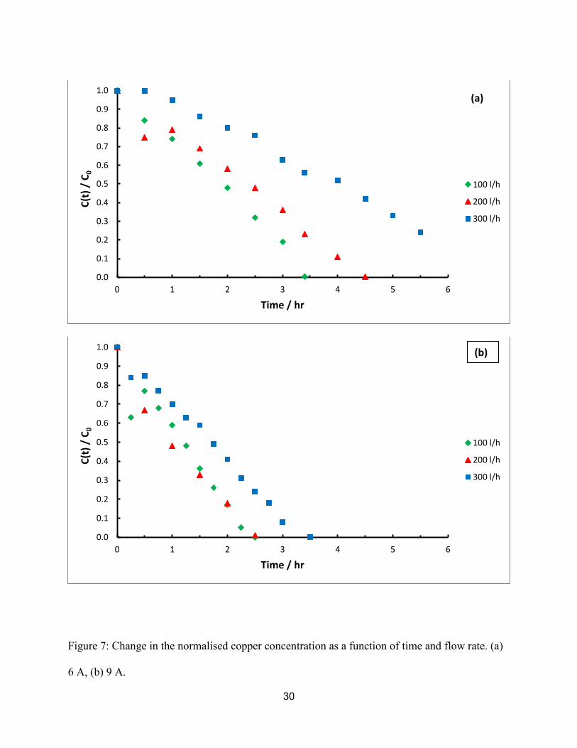
Figure S1(a) (supplementary information) shows the XRD patterns of the copper-
containing waste sludge prior to leaching, and also the leaching residue. The data relating to their
composition is shown in Table 3. The main composition of the galvanic sludge is calcite (94 - 96
9
wt% CaCO3) with a trace amount of silica (1- 2 wt% SiO2). This finding is not unexpected as the
pre-treatment of electronic industrial waste water involves the addition of large amounts of
calcite and calcium hydroxide to precipitate out the metal ions. Similar XRD studies of galvanic
sludge have also shown predominantly calcite and quartz [9,10]. Copper in the form of CuCO3 is
also detected at a concentration of 2 - 3 wt%. Note that other metal precipitates may be
amorphous in nature [9] or have lattice-anomalies [10] and are therefore not identifiable by
XRD.
After leaching and filtering process, the remaining solid was also analysed by XRD and
shown to be predominantly gypsum (CaSO4) with a trace amount of SiO2 (Figure S1(b) –
supplementary information). No CuCO3 was detected which confirms that the leaching process
had removed the majority of the copper from the sludge. The CaSO4 is formed by the reaction of
calcite with sulfuric acid during the leaching process and has been reported in a number of other
studies [9,17]:
CaCO3 + H2SO4 → CaSO4 + H2O + CO2 (1)
3.2 Electrowinning
Initially the recovery of copper ions from simulated leaching solutions containing 7 g l-1
copper in 0.5 M H2SO4 was investigated. The effect of the applied current on the rate of metal
ion recovery at an electrolyte flow rate of 200 l h-1 is shown in Figure 6. As expected, the rate of
copper depletion increases with current density, and at 18 A the concentration has been reduced
to near zero in less than two hours. The change in metal ion concentration as a function of time
in a batch recirculation electrochemical reactor under galvanostatic control has been studied

10
previously [27-29]. In the regime of current-limited control (i.e. below the limiting current) a
linear decrease in concentration, C, is expected according to [28]:
𝐶(𝑡) = 𝐶0 −𝐼𝑡
𝑛𝐹𝑉 (2)
where C0 is the initial concentration, is the current efficiency I is the applied current, t is the
time, n is the number of transferred electrons, F is the Faraday constant and V is the solution
volume. Below the limiting current, and in the absence of any electrochemical side reactions, it is
expected that = 1.
At some later time (t = t’) when the copper concentration is so depleted that the applied
current exceeds the limiting current, the concentration decays exponentially with time according
to [28]:
𝐶(𝑡) = 𝐶′ exp (−𝑘𝐿𝐴
𝑉 (𝑡 − 𝑡′)) (3)
where kL is the mass transport coefficient, A is the electrode area and C’ is the concentration
corresponding to t = t’. Closer inspection of Figure 6 indicates that at low applied currents and
short times the metal ion recovery is occurring under current-limited control and a linear
decrease in concentration is observed. At intermediate currents (6 – 9 A) the linear region
extends to at least C(t)/C0 < 0.1. However, the data obtained at highest current (18 A) displays
some evidence of an exponential decay in concentration at longer times indicating the transition
to mass transport control.
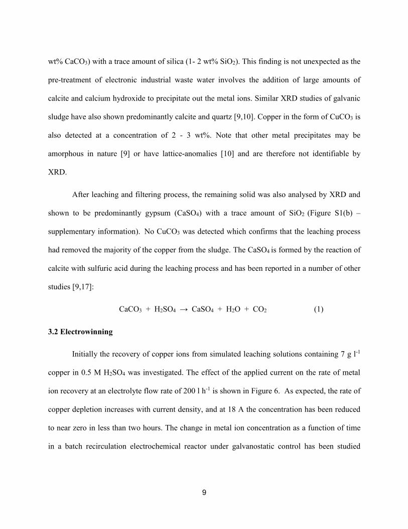
The influence of flow rate on the metal ion recovery is shown in Figure 7 for two
different applied currents. As in the case of Figure 6 there is a general linear decrease in
concentration with time for flow rates of 100 - 300 l h-1 which is indicative of a current-

11
controlled process. Interestingly, reducing the flow rate tends to increase the rate of metal ion
recovery. Referring to equation (2) the only plausible explanation for this behaviour is that the
current efficiency, , is dependent on the flow rate. This is an important finding and will be
analysed in detail in the Discussion section.
The final copper recovery experiment performed utilised a real solution obtained by
leaching the copper-containing sludge (3% w/v) with 0.5 M H2SO4 and then filtering it. The
initial copper concentration was 7 g l-1, the flow rate 100 l h-1 and the applied current was 9 A.
The results of this experiment are shown in Figure 8 alongside the equivalent data for the
simulated leaching solution. In both cases the rate of metal ion recovery is very similar;
indicating that the presence of trace metals (e.g. Fe, Mn and Ni) does not significantly influence
the rate of metal recovery. It has been noted [25,26] that the presence of ferric ions can reduce
the efficiency of copper electrowinning, but under the present electrochemical conditions this
does not seem to be an issue.
3.3 Analysis and Processing of Carbon Felt Cathode
The structure of the carbon felt electrode was examined by SEM before and after
electrowinning and representative images are shown in Figure S2 (supplementary information).
The electrowinning conditions were as follows: I = 9 A, 200 l h-1 flow rate and an experimental
duration of 3 hours. The micrographs indicate that the felt consists of an array of randomly
dispersed, cylindrical carbon fibres with diameters of approximately 15 μm. This is comparable
to the structures reported earlier [30,31] for carbon felt electrodes. In the post electrowinning
images there is clear evidence of copper deposition on the individual fibres.

12
The carbon felt cathode can be re-used but once sufficient copper has been deposited so
that the flow is reduced or blocked it has to be replaced. The metal loading of the cathode can be
conveniently monitored by measuring the pressure drop across the reactor [21]. The final step of
the process would normally be the incineration of the carbon felt in a furnace [30]. Only the
carbon is consumed in the furnace leaving behind high purity copper. The presence of the carbon
improves the quality of the recovered copper by scavenging oxygen or other constituents that
would otherwise reduce its purity.
IV. Discussion
While the results obtained in the electrowinning experiments are broadly as expected, the
unusual dependence of the metal ion recovery rate on the flow rate required further investigation.
To enable this, equation (2) was fitted to the linear portion of the concentration versus time plots
in order to extract the current efficiency. These results are summarised in Table 4 and Figure 9
for all of the electrowinning experiments performed. As noted earlier, because the limiting
current is not exceeded in this linear region, = 1 is often assumed. However, the results shown
in Table 4 and Figure 9 indicate that < 1 in all cases and it tends to be highest at low flow rates
and high applied currents.
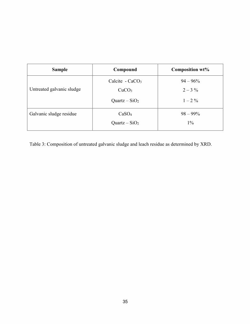
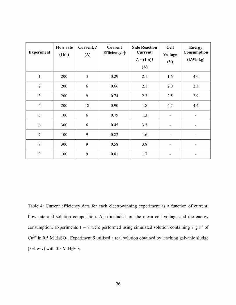
The most plausible explanation for the dependencies observed in Table 4 is that a side
reaction is occurring at the cathode which reduces the overall current efficiency for copper
deposition [29,32]. The current associated with this side reaction (Is = (1-)I) is shown in Table
4. At a fixed flow rate Is is essentially independent of the total applied current, while at a
constant total current Is increases with the electrolyte flow rate. Collectively these results

13
indicate that the current efficiency is been influenced by a parasitic side reaction which is under
mass transport control.
In order to identify the side reactions responsible for the loss of faradaic efficiency it is
necessary to examine all possible electrochemical reactions occurring in the reactor. For the
simulated solutions the electrochemical processes are:
Anode:
2H2O → O2 + 4H+ + 4e- (4)
Cathode:
Cu2+ + 2e- → Cu (5)
2H+ + 2e- → H2 (6)
O2 + 4H+ + 4e- → 2H2O (7)
Ideally, below the limiting current for copper deposition only reaction (5) should occur
and reaction (6) can only commence above it. However, the linear plots shown in Figure 6, 7 and
8 indicate the absence of mass transport control for copper deposition so this reaction can be
ruled out as an explanation for the low current efficiencies observed. The anode reaction will
leave the solution saturated with oxygen which can then be reduced according to cathode
reaction (7). This reaction occurs at a more anodic potential than copper deposition and, due to
its relatively low concentration, will generally occur under mass transport control [32].
In the case of the real solutions obtained by leaching galvanic sludge, the presence of
trace metal ions allows the possibility of additional cathode reactions such as:
Fe3+ + e- → Fe2+ (8)

14
Ni2+ + 2 e- → Ni (9)
The reduction of ferric ions occurs at more noble potentials than for copper but the data in Table
4 indicates that at low concentrations it does not adversely influence the current efficiency of
copper deposition. Nickel deposition occurs at less noble potentials than for copper so should not
co-deposit unless the limiting current for copper deposition is exceeded.
The phenomenon of low faradiac efficiency in electrowinning when the limiting current
for metal ion deposition has not been exceeded has been reported in a number of other studies
employing three-dimensional cathodes [33-39]. For example, Tsapkh and Volkov [33] reported
that during electrowinning with fluidised bed electrodes (FBE) the unusual mass transport and
potential distribution of these 3-D electrodes can lead to an enhancement of the parallel oxygen
reduction reaction thereby lowering the current efficiency. In contrast, under equivalent
conditions using 2-D electrodes the influence of oxygen reduction is negligible. Other
researchers [34-36] employing FBEs have also noted current efficiencies less than unity and its
tendency to increase at higher currents. This has been attributed to corrosion of copper by
oxygen generated at the anode [34,35] or by the development of anodic (i.e. dissolution) zones in
the electrode bed [36]. In some cases the use of inert gas sparging or soluble anodes were shown
[35] to improve the current efficiency, which seems to implicate oxygen either as a direct
reduction or as a corrosion process.
Similar effects have also been observed in other three-dimensional electrode systems [37-
39] and mainly arise from the highly non-uniform potential distribution [21,28]. These have
been analysed [21] for a number of 3D flow-by electrodes with a cylindrical geometry, and these

15
correspond closely to the Porocell configuration shown in Figure 2. Near the cathode feed the
potential (i.e. the current density) is expected to be highest. However, moving radially outwards
toward the anode, the potential and therefore the deposition rate will gradually decrease. Under
some conditions the potential may become insufficient to allow deposition to occur [28]. It is
also possible that sections of the cathode may adopt a potential close to the open circuit potential
for oxygen or ferric ion induced copper corrosion. In these regions any electrodeposited copper
will freely corrode.
As an example, during the electrowinning of copper using a spouted bed electrode (SBE)
reactor [37] it was noted that the presence of oxygen reduced the rate of metal ion recovery and
the current efficiency. This was attributed to the corrosion of copper by oxygen and the effect
could be substantially reduced by sparging the solution with an inert gas. Similar corrosion
effects were also observed during the recovery of nickel ions in a SBE [38]. Scott [39] also
reported low current efficiencies during copper recovery in a moving bed electrode (MBE) and
which increased with applied current. This was partially attributed to corrosion of the copper by
oxygen generated at anode.
A 2012 study by Farrell [40] examining electrowinning from copper-loaded ion exchange
media using a Renocell™ electrochemical reactor is particularly relevant. This system employs a
3-D carbon felt cathode in a configuration which is nearly identical to the Porocell [30]. For
solutions containing 0.5 - 1 g l-1 Cu in H2SO4 at pH = 0.5 they observed: (i) current-limiting
behaviour and (ii) a tendency for the metal ion recovery rate to decrease at high flow rates. They
also reported that the current efficiency was higher at high currents (cf. = 0.42 - 0.61 at 7.5 A;
= 0.34 - 0.48 at 5 A) and, at a fixed current, declined with increasing flow rate. Collectively,
these results are in good agreement with the present study (Figure 9). The authors attributed

16
some of the observed effects to hydrogen gas evolution blocking the active cathode area or, more
plausibly, arising from the complex geometry and current distribution of the 3-D cathode. The
possible influence of oxygen reduction or a corrosion process was not considered by the authors.
Comparing the present results to these previous findings it seem likely that the reduced
current efficiency observed is due to either: (i) direct reduction of oxygen or (ii) oxygen induced
corrosion. Regardless of the exact mechanism, the rate of this parasitic reaction will be
necessarily controlled by the transport of to the electrode surface. The experimental results
indicate that the influence of this side reaction can be minimised by operating at low flow rates
and high applied currents. As reported by others [36-38] the use of inert gas sparging may also
improve the current efficiency. Operating at higher temperatures would also reduce the solubility
of O2 and therefore its influence on the current efficiency for copper deposition, but with an
increased energy cost. Another alternative is to use a ‘divided’ Porocell configuration which
separates the anode and cathode processes using a cation exchange membrane [19]. This will
prevent O2 generated at the anode reacting at the cathode but with some increase in the
complexity and cost of the reactor.
In the case of the real solutions, there is an additional possibility that the co-reduction of
ferric ions also contributes to a loss in current efficiency. Analogous with the situation for
oxygen, this can occur by a direct reduction or a corrosion process [25,26] and, due to the low
iron concentration (< 1000 ppm), will generally occur under mass transport limited conditions.
To investigate this possibility, we have calculated the ratio of the limiting current for O2 and Fe3+
reduction using their respective concentrations and diffusion coefficients in 0.5 M H2SO4
[32,41]. These calculations indicate that, even if we assume all the iron in solution is in the form
of Fe3+, the limiting current is less than 25% that for O2. The fact that the current efficiency is

17
similar in the real and simulated solutions (Figure 8 and Table 4) also indicates that the role of
ferric ion reduction is a relatively minor one.
A final consideration in the copper recovery experiments is the overall energy
consumption [28]. The electrical energy requirements for experiments 1 - 4 have been calculated
from the cell voltage and current efficiency, and are reported in Table 4. They typically ranged
from 2.5 – 4.6 kWh kg. These results are comparable to the values obtained for other 3D
electrodes when electrowinning from concentrated copper solutions [39,40] but higher than those
reported [25] for conventional copper electrowinning (ca. 2 kWh kg). Notably, the conditions
corresponding to the highest current efficiency also resulted in the highest energy consumption,
so that optimisation of the copper recovery involves careful consideration of both of these
factors.
V. Conclusion
A process flow for the recovery of copper from galvanic sludge waste using a
combination of leaching, filtration and electrowinning has been developed. Acid leaching was
found to be an effective means for extracting the copper from the sludge, and the optimum
conditions were 0.5 M H2SO4 and leach time of 90 minutes. The leaching was not very selective
compared to base leaching but the presence of trace metal ions such as manganese, iron and
nickel did not adversely affect the subsequent electrowinning step.
Copper was then recovered by electrowinning in a batch recirculation
electrochemical reactor employing a 3-D carbon felt cathode. The influence of applied current,
flow rate and the presence of other metal ions on the rate and efficiency of copper electrowinning

18
was investigated. It was found that the current efficiency was low (typically = 0.30 - 0.90) even
though electrowinning was performed below the limiting current for copper deposition. The low
current efficiency arises due to the occurrence of a side reaction, most probably the reduction of
dissolved oxygen or oxygen-induced corrosion.
The influence of this parasitic side reaction can be minimized by operating at
relatively high currents and at low flow rates. For example, electrowinning at an applied current
of 18 A and a flow rate of 200 l h-1 resulted in a current efficiency of = 0.90 and > 99% of the
copper was recovered in less than 2 hours. However, under these conditions the energy
consumption was higher than at lower currents. Further optimisation of the electrochemical
reactor is planned, and these results along will be reported in a subsequent paper. In addition,
issues associated with the recycling of the leachant such as control of pH, viscosity and
conductivity, and the build-up of impurities will also be addressed. This will be followed by an
industrial-scale trial in Vietnam using galvanic sludge waste supplied by Urenco.
Acknowledgements
We acknowledge support from British Council Newton Fund-Researcher Links Travel Grant
and UK Institutional Links grant (Ref 172711746).

19
References
1. Odele R.R., Martinez I., Deets L.A., 1991. The recycling of hazardous metal plating
wastes. JOM 43, 28-31.
2. Magalhaes J.M., Silva J.E., Castro F.P., Labrincha J.A., 2005. Physical and chemical
characterisation of metal finishing industrial wastes. J. Environmental Management 75,
157-166.
3. Silva A.C., Mello-Castanho S., 2008. Incorporation of galvanic waste (Cr, Ni, Cu, Zn,
Pb) in a soda-lime-borosilicate glass. J. Am. Ceram. Soc. 91, 1300-1305.
4. Magalhaes J.M., Silva J.E, Castro F.P., Labrincha J.A., 2004. Effect of experimental
variables on the inertization of galvanic sludges in clay-based ceramics. J. Hazard. Mat.
106B, 139-147.
5. Luz C.A., Rocha J.C., Cheriaf M., Pera J., 2006. Use of sulfoaluminate cement and
bottom ash in the solidification/stabilization of galvanic sludge. J. Hazard. Mat. B136,
837-845.
6. Perez-Villarejo L., Martinez-Martinez S., Carrasco-Hurtado, B., Eliche-Quesada D,
Urena-Nieto C., Sanchez-Soto P.J., 2015. Valorization and inertization of galvanic sludge
waste in clay bricks. Applied Clay Science 105-106, 89-99.
7. Bernardes, A.M., Bohlinger, I., Wuth, W., 1996. The thermal treatment of galvanic
sludges for environmental compatibility. JOM 48, 59-62.
8. Amaral, F.A.D., dos Santos V.S., Bernardes A.M., 2014. Metal recovery from galvanic
sludge by sulfate roasting and thiosulfate leaching. Miner. Eng. 60, 1 – 7.

20
9. Miskufova A., Havlik T., Laubertova M., Ukasik, M., 2006. Hydrometallurgical route for
copper, zinc and chromium from galvanic sludge. Acta Metallurgica. Slovaca 12, 293-
302.
10. Wazeck J., 2013. Heavy metal extraction from electroplating sludge using Bacillus
subtilis and Saccharomyces cerevisiae. Geologica Saxonica 59, 251-258.
11. Vilarinho C., Castro F., Carneiro F., Ribeiro A., 2013. Development of a process for
copper recovering from galvanic sludges. Materials Science Forum 730-732, 575-580.
12. Silva J.E., Paiva A.P., Soares D., Labrincha, A., Castro F., 2005. Solvent extraction
applied to the recovery of heavy metals from galvanic sludge. J. Hazard. Mat. B120, 113-
118.
13. Jandova J., Stefanova T., Niemczykov R., 2000. Recovery of Cu-concentrates from waste
galvanic copper sludges. Hydrometallurgy 57, 77-84.
14. Fornari P., Abbruzzese C., 1999. Copper and nickel selective recovery by electrowinning
from electronic and galvanic industrial solutions. Hydrometallurgy 52, 209-222.
15. Veglio F., Quaresima R., Fornari, P., Ubaldini S., 2003. Recovery of valuable metals
from electronic and galvanic industrial wastes by leaching and electrowinning. Waste
Management 23, 245-252.
16. Rossini, G., Bernardes A.M., 2006. Galvanic sludge metals recovery by pyro-
metallurgical and hydrometallurgical treatment. J. Hazard. Mat. 131, 210-216.
17. Silva J.E., Soares D., Paiva A.P., Labrincha J.A., Castro F., 2005. Leaching behaviour of
a galvanic sludge in sulphuric acid and ammoniacal media. J. Hazard. Mat. B121, 195-
202.

21
18. Xiao Y., Yang Y., van den Berg J., Sietsma J., Agterhuis, H., Visser G., Bol D., 2013.
Hydrometallurgical recovery of copper from complex mixtures of end-of-life shredded
ICT products. Hydrometallurgy 140, 128-134.
19. Sunderland J.G., Dalrymple I.M., Cell and method for the recovery of metal ions from
dilute solutons, US Patent 5,690,806
20. Roy S., Gupte Y., Green T.A., 2001. Flow cell design for metal deposition at recessed
circular electrodes and wafers. Chem. Eng. Science 56, 5025-5035.
21. Ferreira B.K., 2008. Three-dimensional electrodes for the removal of metals from dilute
solutions: A review. Mineral Processing and Extractive Metallurgy Review 29:4, 330-
371.
22. Campbell D.A., Dalrymple I.M., Sunderland J.G., Tilson D., 1994. The electrochemical
recovery of metals from effluent and process streams. Resources Conservation and
Recycling 10, 25-33.
23. Friedrich J.M., Ponce-de-Leon C., Reade G.W., Walsh F.C., 2004. Reticulated vitreous
carbon as an electrode material. J. Electroanal. Chem. 561, 203-217.
24. Silva-Martinez S., Roy S., 2013. Copper recovery from tin striping solution:
Galvanostatic deposition in a batch-recycle system. Sep. Pur. Technol. 118, 6-12.
25. Cooper W.C., 1985. Advances and future prospects in copper electrowinning. J. Appl.
Electrochem., 15, 789-805.
26. Hatfield, T.L. Kleven T.L., Pierce D.T., 1996. Electrochemical remediation of metal-
bearing wastewaters Part II: Corrosion-based inhibition of copper removal by iron (III). J.
Appl. Electrochem. 28, 397-403.

22
27. Stankovic V.D., Wragg A.A., 1995. Modelling of time-dependent performance criteria in
a three-dimensional cell system during batch recirculation copper recovery. J. Appl.
Electrochem. 25, 565-573.
28. Pletcher D., Walsh F.C., 1993. Industrial Electrochemistry, second ed. Blackie Academic
and Professional.
29. Silva-Martinez S., Roy. S., 2016. Metal recovery from low concentration solutions using
a flow-by reactor under galvanostatic approach. Russ. J. Electrochem. 52, 71-77.
30. Pletcher D., 2009. A First Course in Electrode Processes, second ed., RSC Publishing, pp
263-268.
31. Gonzalez-Garcia J., Bonete, P., Exposito E., Montiel V., Aldaz A., Torregrosa-Macia R.,
1999. Characterization of a carbon felt electrode: structural and physical properties. J.
Mater. Chem. 9, 419-426.
32. Scott K, Paton E.M., 1993. An analysis of metal recovery by electrodeposition from
mixed metal ion solutions - Part I. Theoretical behaviour of batch recycle operation.
Electrochim. Acta. 38, 2181-2189.
33. Tsapakh S.L., Volkov L.V., Fluidized-bed electrodeposition of heavy non-ferrous metals,
P.L. Claessens P.L., Harris G.B. (eds), Proceedings of the International Symposium on
Electrometallurgical Plant Practice, Montreal, Quebec, Canada, October 21-24, 1990.
34. Coeuret F., 1980. The fluidized bed electrode for the continuous recovery of metals. J.
Appl. Electrochem. 10, 687-696.
35. Flett D.S, 1972. The fluidised-bed electrode in extractive metallurgy. Chem. Ind. 52, 983-
988.

23
36. Hutin D., Coeuret F., 1977. Experimental study of copper deposition in a fluidized bed
electrode. J. Appl. Electrochem. 7, 463-471.
37. Shirvanian P.A., Calo J.M., 2005. Copper recovery in a spouted vessel electrolytic
reactor (SBER). J. Appl. Electrochem. 35, 101-111.
38. Grimshaw P., Calo J.M., Shirvanian P.A., Hradil G., 2011. Electrodeposition/removal of
nickel in a spouted electrochemical reactor. Ind. Eng. Chem. Res. 50, 9525-9531.
39. Scott K., 1981. Metal recovery using a moving–bed electrode. J. Appl. Electrochem. 11,
339-346.
40. Hubler D.K., Baygents J.C., Farrell J., 2012. Sustainable electrochemical regeneration of
copper-loaded ion exchange media. Ind. Chem. Eng. Res. 51, 13259-13267.
41. Bisang J.M., 1996. Theoretical and experimental studies of the effect of side reactions in
copper deposition from dilute solutions on packed-bed electrodes. J. Appl. Electrochem.
26, 135-142.

24
Leaching
Filtration
Electrowinning
WashingLeaching solution
Leachant
Leaching Residue
Galvanic Sludge
PureCopper
Acid solution
CathodeIncineration
Figure 1: Proposed process flowsheet for recovery of copper from galvanic sludge waste.

25
Figure 2. Schematic showing the internal structure of the Porocell reactor.

26
Figure 3: Images of the carbon felt cathode before and after electrowinning.

27
Figure 4: Effect of the sulfuric acid concentration on the amount of copper recovered for the 3%
w/v and 10% w/v solutions for a leaching time of 30 minutes.
0
5
10
15
20
25
0.1 M 0.5 M 1.0 M 2.0 M
[Cu
2+ ]
/ g
l-1
[H2SO4]
3 wt%
10 wt%

28
Figure 5: Effect of the leaching time and acid concentration (0.5 or 1.0 M H2SO4) on the amount
of copper recovered.
0.0
5.0
10.0
15.0
20.0
25.0
0 0.5 1 1.5 2 2.5 3
[Cu
2+ ]
/ g
l-1
Leaching Time / hr
3% w/v, 0.5 M
3% w/v, 1.0 M
10% w/v, 1.0 M

29
Figure 6: Change in the normalised copper concentration as a function of time and various
applied current at a flow rate of 200 l h-1.
0.0
0.1
0.2
0.3
0.4
0.5
0.6
0.7
0.8
0.9
1.0
0 1 2 3 4 5 6 7
C(t
) /
C0
Time / hr
18 A
9 A
6 A
3 A
30
Figure 7: Change in the normalised copper concentration as a function of time and flow rate. (a)
6 A, (b) 9 A.
0.0
0.1
0.2
0.3
0.4
0.5
0.6
0.7
0.8
0.9
1.0
0 1 2 3 4 5 6
C(t
) /
C0
Time / hr
100 l/h
200 l/h
300 l/h
(a)
0.0
0.1
0.2
0.3
0.4
0.5
0.6
0.7
0.8
0.9
1.0
0 1 2 3 4 5 6
C(t
) /
C0
Time / hr
100 l/h
200 l/h
300 l/h
(b)

31
Figure 8: Comparison of the metal recovery rate in simulated and real solutions. Electrowinning
conditions: I = 9 Amps, 100 l h-1 flow rate.
0.0
0.1
0.2
0.3
0.4
0.5
0.6
0.7
0.8
0.9
1.0
0 0.5 1 1.5 2 2.5 3
C(t
) /
C0
Time / h
Simulated
Real

32
Figure 9: Dependence of the current efficiency for copper deposition on the applied current and
flow rate.
0
0.1
0.2
0.3
0.4
0.5
0.6
0.7
0.8
0.9
1
50 100 150 200 250 300 350
Cu
rren
t Ef
fici
ency
,
Flowrate / l h-1
18 A
9 A
6 A
3 A

33
Element wt.%
Cr 0.01
Mn 1.37
Fe 6.78
Ni 0.12
Cu 21.5
Mg 3.32
Ca 20.7
Al 0.26
Table 1: Elemental composition of galvanic sludge determined by ICP analysis.

34
1 M
(NH4)2SO4
2 M
(NH4)2SO4
1 M
(NH4)2SO4
+
1 M NH4OH
0.5 M H2SO4
1.0 M H2SO4
Cr* 0.148 0.135 0.360 2.00 2.12
Mn* 44.7 68.0 12.7 159 218
Fe* 5.65 5.89 7.22 589 1005
Ni* 37.1 36.1 48.7 75.6 128
Cu* 1690 2805 4905 6330 7225
Cu† - - - 5885 -
Table 2. Composition of solution (mg l-1) leached from 3% w/v galvanic sludge using basic and
acidic lixiviants. Concentrations determined by UV-Vis (†) and ICP-MS (*) measurements.
35
Sample Compound Composition wt%
Untreated galvanic sludge
Calcite - CaCO3
CuCO3
Quartz – SiO2
94 – 96%
2 – 3 %
1 – 2 %
Galvanic sludge residue CaSO4
Quartz – SiO2
98 – 99%
1%
Table 3: Composition of untreated galvanic sludge and leach residue as determined by XRD.
36
Table 4: Current efficiency data for each electrowinning experiment as a function of current,
flow rate and solution composition. Also included are the mean cell voltage and the energy
consumption. Experiments 1 – 8 were performed using simulated solution containing 7 g l-1 of
Cu2+ in 0.5 M H2SO4. Experiment 9 utilised a real solution obtained by leaching galvanic sludge
(3% w/v) with 0.5 M H2SO4.
Experiment
Flow rate
(l h-1)
Current, I
(A)
Current
Efficiency,
Side Reaction
Current,
Is = (1-)I
(A)
Cell
Voltage
(V)
Energy
Consumption
(kWh kg)
1 200 3 0.29 2.1 1.6 4.6
2 200 6 0.66 2.1 2.0 2.5
3 200 9 0.74 2.3 2.5 2.9
4 200 18 0.90 1.8 4.7 4.4
5 100 6 0.79 1.3 - -
6 300 6 0.45 3.3 - -
7 100 9 0.82 1.6 - -
8 300 9 0.58 3.8 - -
9 100 9 0.81 1.7 - -

37
Figure S1: X-ray diffractograms of (a) untreated galvanic mud (b) leaching residue.

38
Figure S2: SEM images of carbon felt electrode before (upper images) and after (lower images)
after copper electrowinning at 9 A for 3 hours at a flow rate 200 l h-1.