electro-mechanical-thermal modeling of high temperature
TRANSCRIPT

Electro-mechanical-thermal Modeling of High Temperature Superconducting Cables
Yuanwen Gao, Wurui Ta, Youhe ZhouDepartment of Mechanics and Engineering Sciences, College of Civil Engineering and
Mechanics, Lanzhou University, Lanzhou, Gansu 730000, P.R. China
Email:[email protected]
15 - 17 June, 2016 - Bologna, Italy
HTS Modelling 2016
Contents
� Introduction
� Single tape modelling
� Electromechanical behavior of TSTC HTS Cable
� Electro-mechanical-thermal behavior of TSSC HTS CICC
� Conclusions
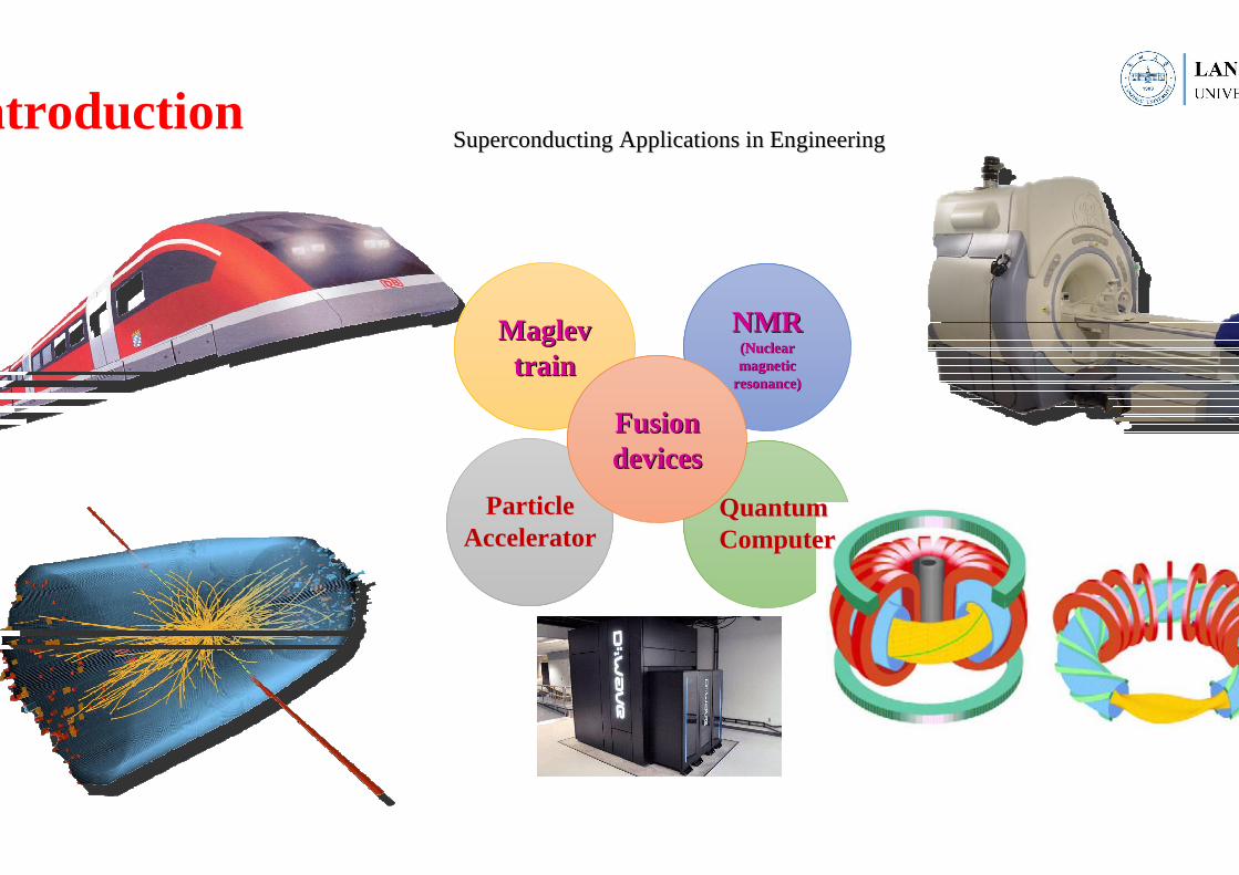
Maglev Maglev traintrain
NMRNMR(Nuclear (Nuclear magnetic magnetic
resonance) resonance)
Superconducting Applications in EngineeringSuperconducting Applications in EngineeringIntroduction
Particle Particle AcceleratorAccelerator
Quantum Quantum ComputerComputer
Fusion Fusion devicesdevices
NbNbTi
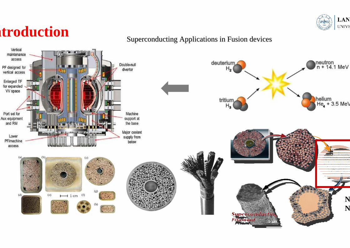
IntroductionSuperconducting Applications in Fusion devicesSuperconducting Applications in Fusion devices

L Muzzi et al., Supercond. Sci. Technol.2015
� Compared to LTS materials, HTS materials exhibit higher critical magnetic fields and higher current densities, specific heats, thermal conductivities, and lower required refrigeration power , which make them potential candidates for large magnets in future.。。。。
Introduction
2G coated conductors2G coated conductors
Barth C. High temperature superconductor cable concepts for fusion. 2013
CORC
TSSC
TSTCROEBEL
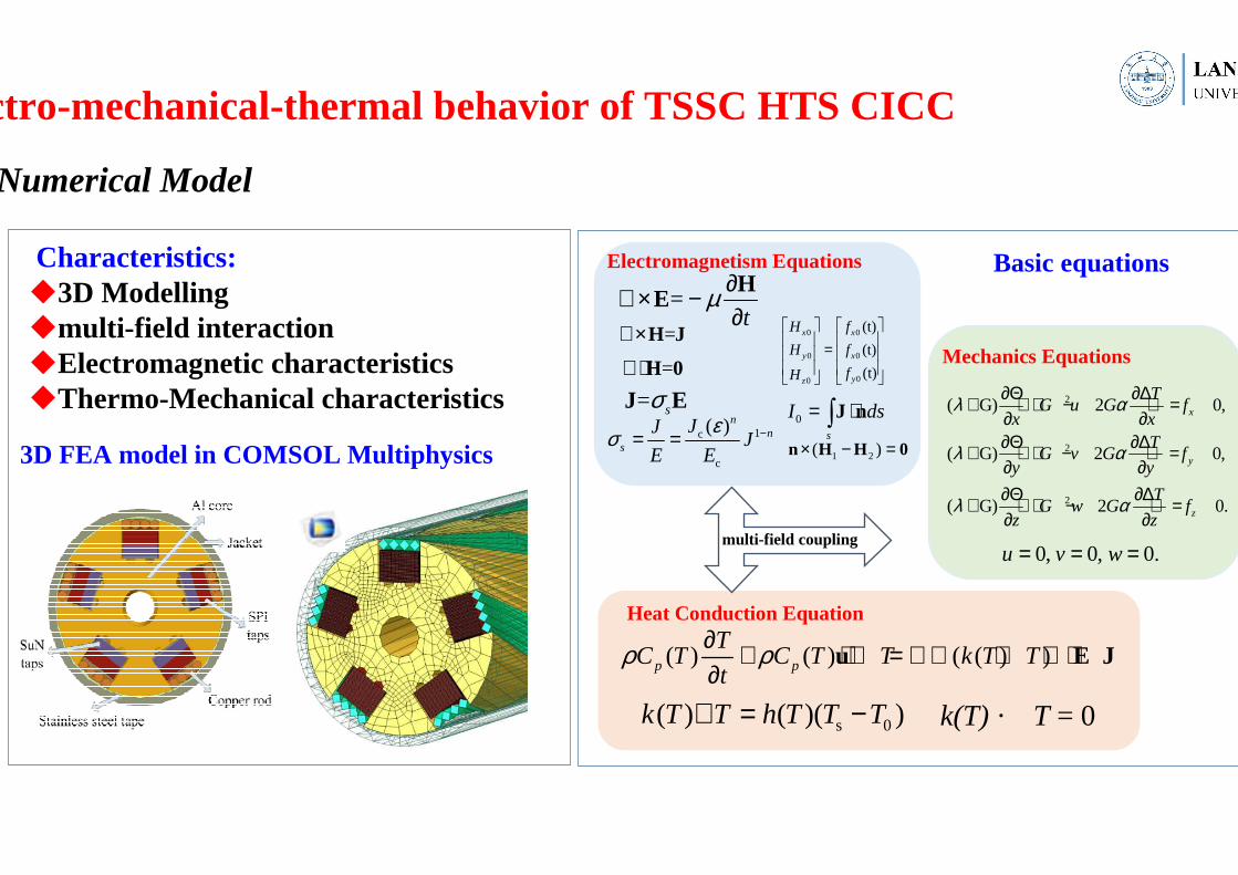
TSTC HTS Cable: �The cable consists of a stack of flat tapes twisted along the axis of the stack, and embedding the stack in single groove machined on a circular rod.TSSC HTS CICC:�The HTS tapes are arranged as five ducts wound on a helically slotted Al core with an external round jacket. �A central channel and two semicircular grooves provide channels for coolant flow. �The Al core with tapes are wrapped with 50-100 µm stainless steel tape and jacketed with 1.25 mm Al foil prior to the final compaction process.
TSTC(twisted stacked-tape cable conductor) TSSC(twisted-stacked slotted core)HTS CICC

Introduction Research Status-Experiment research
TSTC HTS Cable-Electric properties
Makoto Takayasu, Luisa Chiesa, et. al. Present Status and Recent Developments of the Twisted Stacked-Tape Cable (TSTC) Conductor. 2015
TSSC HTS CICC-Electric properties
G. Celentano, G. De Marzi.et.al. ,2014 A. Augieri, G. De Marzi.et .al., 2015 Gianluca De Marzi, Giuseppe Celentano. et. Al., 2015
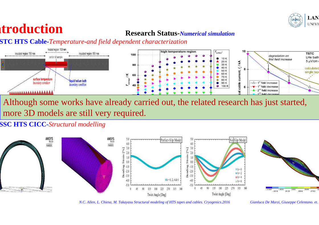
Research Status-Numerical simulation Introduction
TSSC HTS CICC-Structural modelling
N.C. Allen, L. Chiesa, M. Takayasu Structural modeling of HTS tapes and cables. Cryogenics.2016 Gianluca De Marzi, Giuseppe Celentano. et. Al., 2015
TSTC HTS Cable-Temperature-and field dependent characterization
Barth C. High temperature superconductor cable concepts for fusion. 2013
Although some works have already carried out, the related research has just started, more 3D models are still very required.

The structure diagram of 2G coated conductorsThe structure diagram of 2G coated conductors:::::::: TapeTape
1. Forming the elastic stiffness matrix Ke。
2. Solving elasticity problem
a(1)=Ke-1Q (n=1,2…)
3. Calculate the equivalent strain of every Gauss integration
points。
4.
5. Calculate the elastic shear modulus of every Gauss
integration points
6. Forming the plastic stiffness matrix Kp(n)
7. Solving plastic problem
a(n+1)=(Kep(n))-1Q
8. Check convergence
9. Output
Finite Element Equation( ) =a a Qe pK
Iterative process:
(n )
( )sσ ε−
sσ ε−
−
( n 1 ) ( n )
(n 1 )
aae r
a
+
+
−≤Mesh consists of 1350 domain elements, 1935 boundary elements, and
444 edge elements. The bilinear properties for each elastic-plastic material were taken from stress–strain data at 77 K.
MeshMesh Bilinear isotropic hardening material model
Single tape modelling
Copper Stabilizer
Silver overlayer
Substrate REBCO/Buffer
E(GPa) 350 90 180 150
T(GPa) 4 22 7.5 -
Y(MPa) 85 225 1225 -
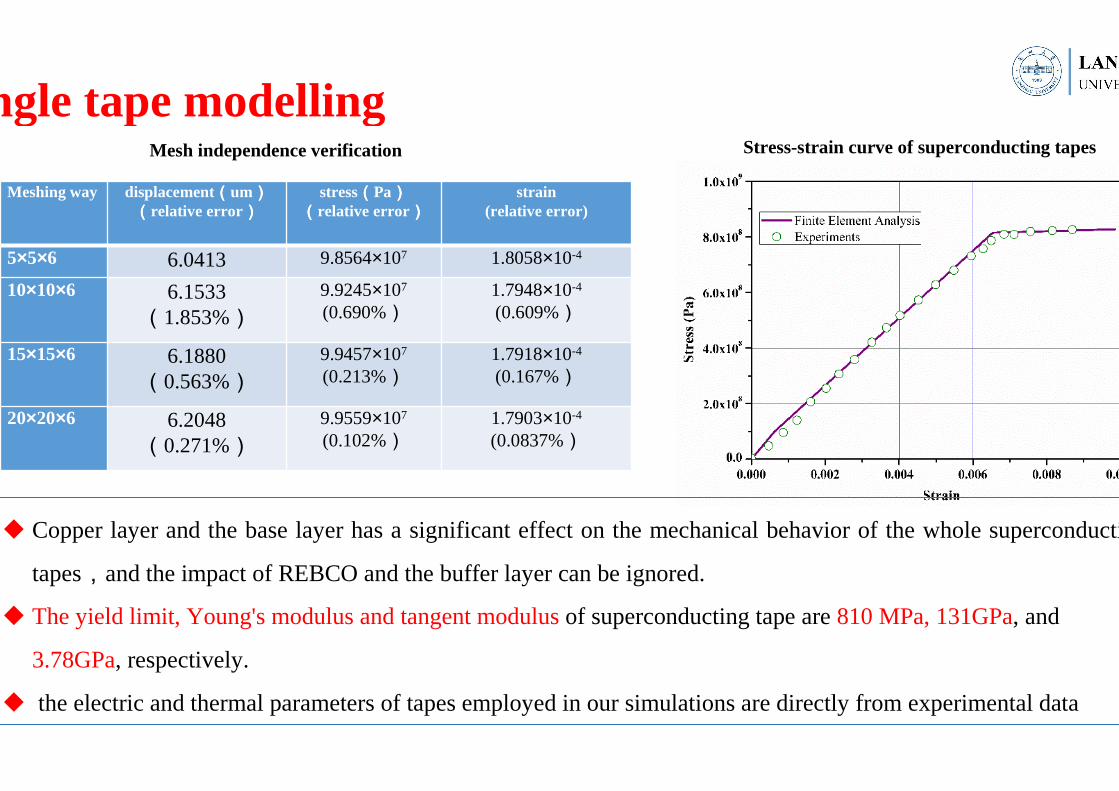
Meshing way displacement((((um))))((((relative error))))
stress((((Pa))))((((relative error))))
strain(relative error)
5×5×6 6.0413 9.8564×10⁷ 1.8058×10⁻⁴
10×10×6 6.1533(1.853%)
9.9245×10⁷
(0.690%)1.7948×10⁻⁴
(0.609%)
15×15×6 6.1880(0.563%)
9.9457×10⁷
(0.213%)1.7918×10⁻⁴
(0.167%)
20×20×6 6.2048(0.271%)
9.9559×10⁷
(0.102%)1.7903×10⁻⁴
(0.0837%)
Single tape modelling
� Copper layer and the base layer has a significant effect on the mechanical behavior of the whole superconducting
tapes,and the impact of REBCO and the buffer layer can be ignored.
� The yield limit, Young's modulus and tangent modulus of superconducting tape are 810 MPa, 131GPa, and
3.78GPa, respectively.
� the electric and thermal parameters of tapes employed in our simulations are directly from experimental data
Mesh independence verification Stress-strain curve of superconducting tapes
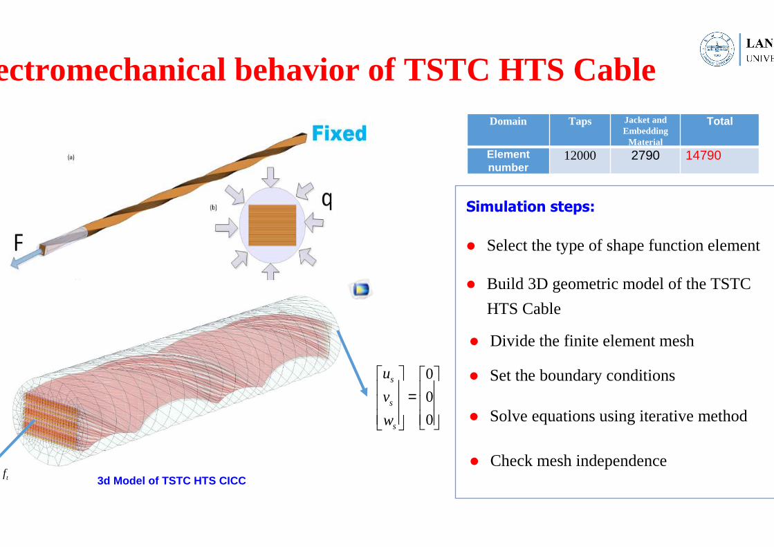
Electromechanical behavior of TSTC HTS CableDomain Taps Jacket and
Embedding Material
Total
Element number
12000 2790 14790
3d Model of TSTC HTS CICC
0
0
0
s
s
s
u
v
w
=
tfn =
� Select the type of shape function element
� Build 3D geometric model of the TSTC
HTS Cable
� Divide the finite element mesh
� Set the boundary conditions
� Solve equations using iterative method
Simulation steps:
� Check mesh independence
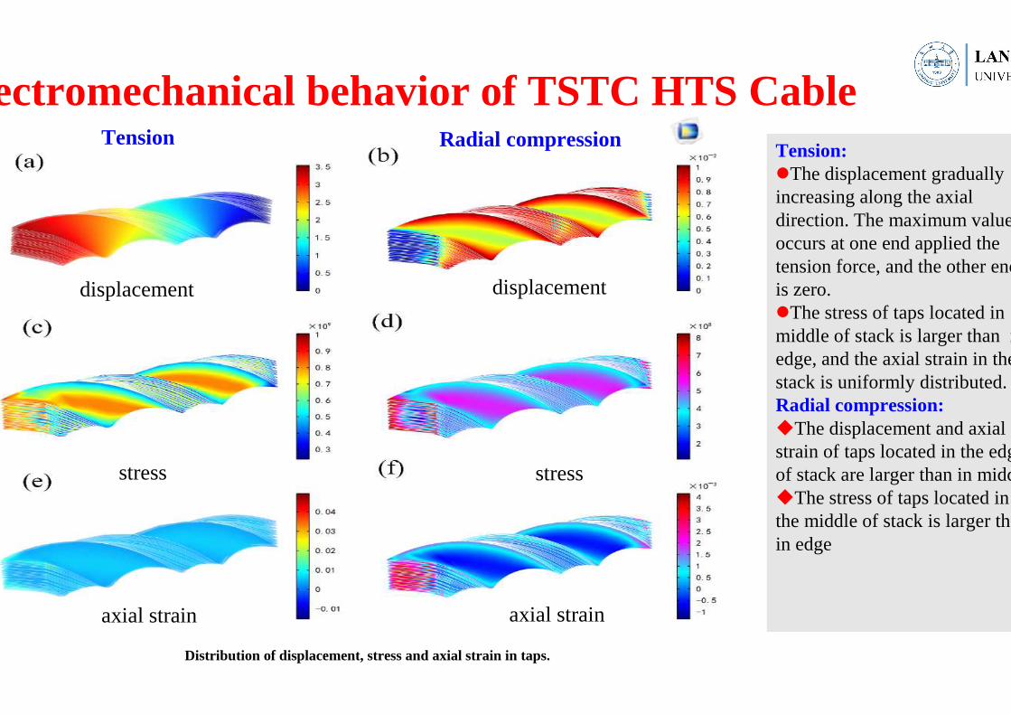
Electromechanical behavior of TSTC HTS CableTension:�The displacement gradually increasing along the axial direction. The maximum value occurs at one end applied the tension force, and the other end is zero. �The stress of taps located in middle of stack is larger than in edge, and the axial strain in the stack is uniformly distributed.Radial compression:�The displacement and axial strain of taps located in the edge of stack are larger than in middle.�The stress of taps located in the middle of stack is larger than in edge
Tension Radial compression
displacement displacement
stress stress
axial strain axial strain
Distribution of displacement, stress and axial strain in taps.
Electromechanical behavior of TSTC HTS Cable
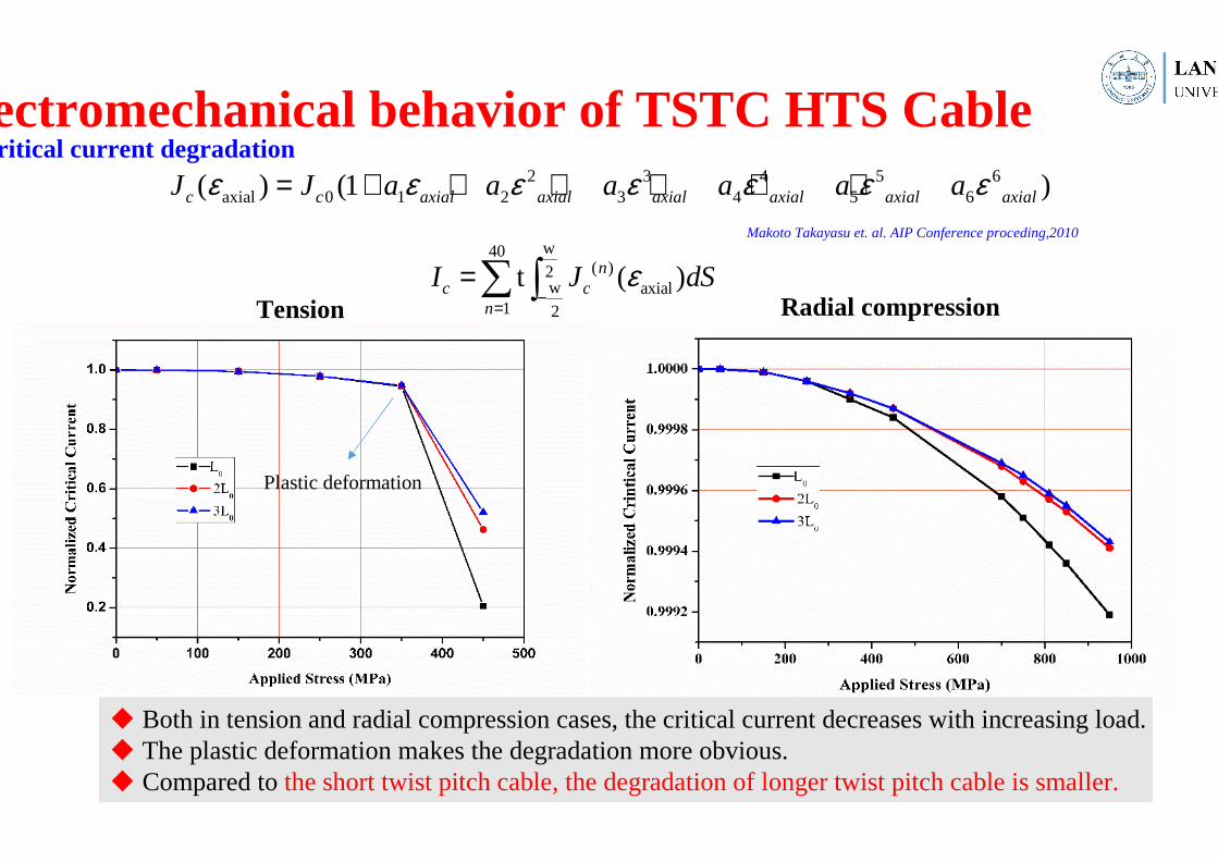
w40( )2
w axial1 2
t ( )nc c
n
I J dSε−=
=∑ ∫
2 3 4 5 6axial 0 1 2 3 4 5 6( ) (1 )c c axial axial axial axial axial axialJ J a a a a a aε ε ε ε ε ε ε= + + + + + +
Critical current degradation
Tension Radial compression
� Both in tension and radial compression cases, the critical current decreases with increasing load.� The plastic deformation makes the degradation more obvious.� Compared to the short twist pitch cable, the degradation of longer twist pitch cable is smaller.
Plastic deformation
Makoto Takayasu et. al. AIP Conference proceding,2010
Numerical Model
1c
c
( )nn
s
JJJ
E E
εσ −= =0
s
I ds= ⋅∫J n
( ) ( ) ( ( ) )p p
TC T C T T k T T
tρ ρ∂ + ⋅∇ = ∇ ⋅ ∇ + ⋅
∂u E J
s 0( ) ( )( )k T T h T T T∇ = −
0, 0, 0.u v w= = =
Electromagnetism Equations
Heat Conduction Equation
Mechanics Equations
multi-field coupling
Electro-mechanical-thermal behavior of TSSC HTS CICC
=∇×H J
=t
µ ∂∇× −∂H
E
= sσJ E=∇⋅H 0
0 0
0 0
00
(t)
(t)
(t)
x x
y x
yz
H f
H f
fH
=
1 2( )× − =n H H 0
2
2
2
( G) 2 0,
( G) 2 0,
( G) 2 0.
x
y
z
TG u G f
x xT
G v G fy y
TG w G f
z z
λ α
λ α
λ α
∂Θ ∂∆+ + ∇ − + =∂ ∂∂Θ ∂∆+ + ∇ − + =∂ ∂∂Θ ∂∆+ + ∇ − + =∂ ∂
Characteristics:�3D Modelling�multi-field interaction�Electromagnetic characteristics �Thermo-Mechanical characteristics
3D FEA model in COMSOL Multiphysics
Basic equations
k(T) ·�T = 0

vector basis function(a)N1e (b) N2
e (c) N3e
j(x) t 1 (x edge)
(x) t 0 (x )
ej
ej k
N j
N other edge
⋅ = ∈ −
⋅ = ∈
(x) 0ejN∇ ⋅ = =∇⋅H 0
Domain Taps Al core Copper rods
stainless steel tape
Al foil Air Total
Element number
15000 19470 19670 20930 22780 18470 116320
3d Model of TSSC HTS CICC
B=15T
0 0, ( sin(2 ))e
s
I ds I I ftπ= ⋅ =∫ J nEdge elementEdge element
Mesh
L=200mm
Electro-mechanical-thermal behavior of TSSC HTS CICC
0
0
0s
=
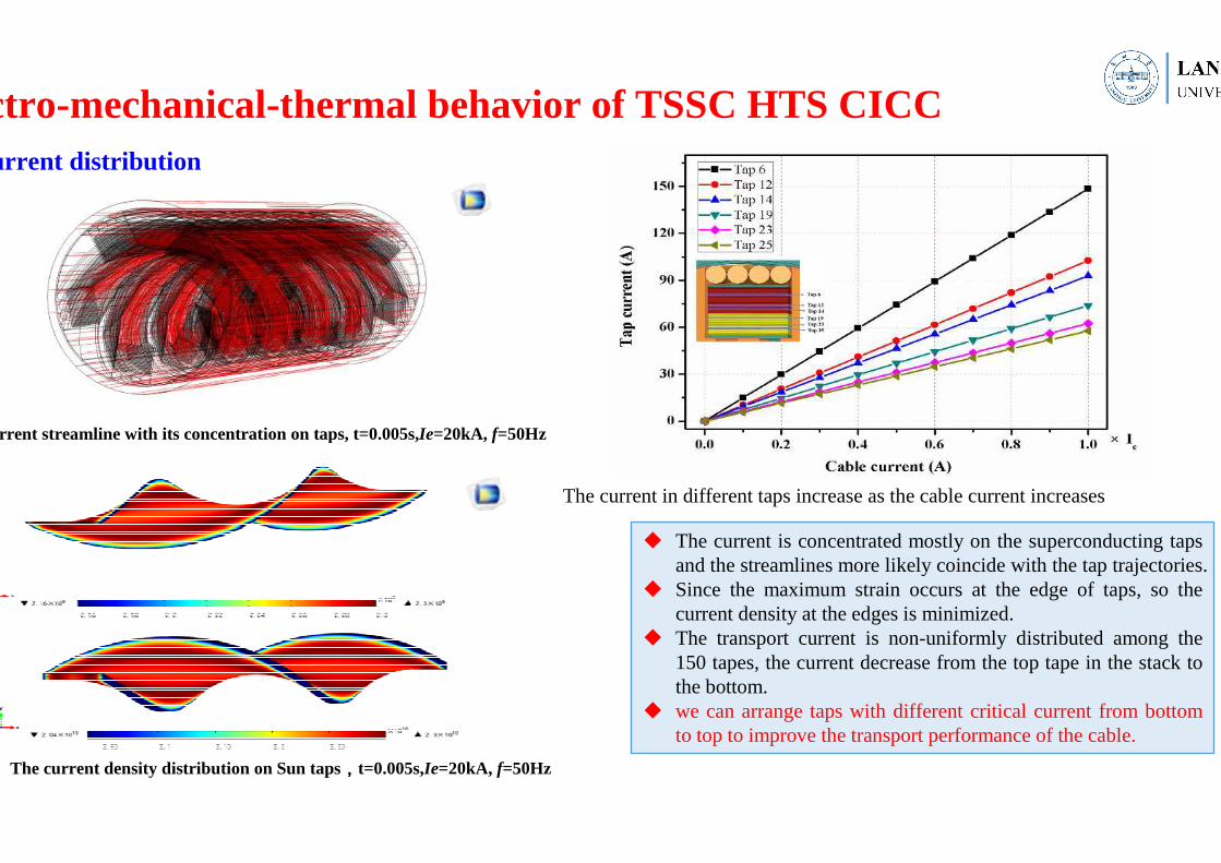
� The current is concentrated mostly on the superconducting taps and the streamlines more likely coincide with the tap trajectories.
� Since the maximum strain occurs at the edge of taps, so the current density at the edges is minimized.
� The transport current is non-uniformly distributed among the 150 tapes, the current decrease from the top tape in the stack to the bottom.
� we can arrange taps with different critical current from bottom to top to improve the transport performance of the cable.
Current streamline with its concentration on taps, t=0.005s,Ie=20kA, f=50Hz
The current density distribution on Sun taps,,,,t=0.005s,Ie=20kA, f=50Hz
The current in different taps increase as the cable current increases
Current distribution
Electro-mechanical-thermal behavior of TSSC HTS CICC
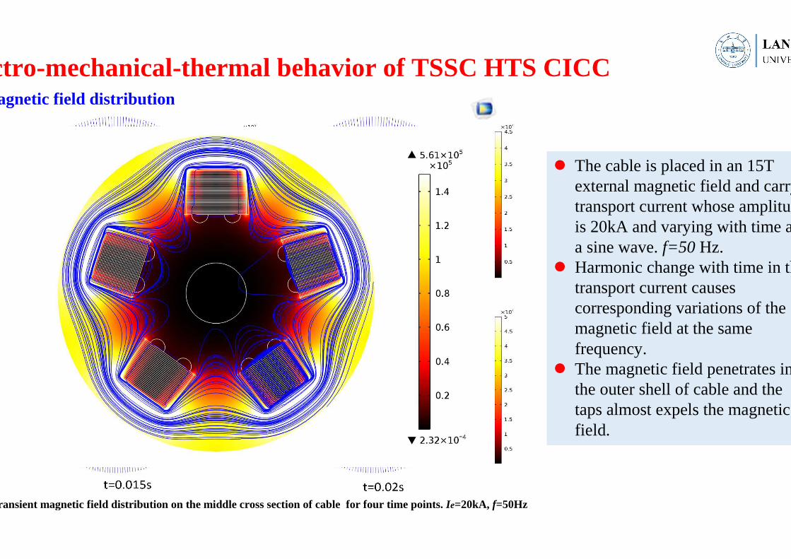
Transient magnetic field distribution on the middle cross section of cable for four time points. Ie=20kA, f=50Hz
� The cable is placed in an 15T external magnetic field and carry a transport current whose amplitude is 20kA and varying with time as a sine wave. f=50 Hz.
� Harmonic change with time in the transport current causes corresponding variations of the magnetic field at the same frequency.
� The magnetic field penetrates in the outer shell of cable and the tapsalmost expels the magnetic field.
Magnetic field distribution
Electro-mechanical-thermal behavior of TSSC HTS CICC
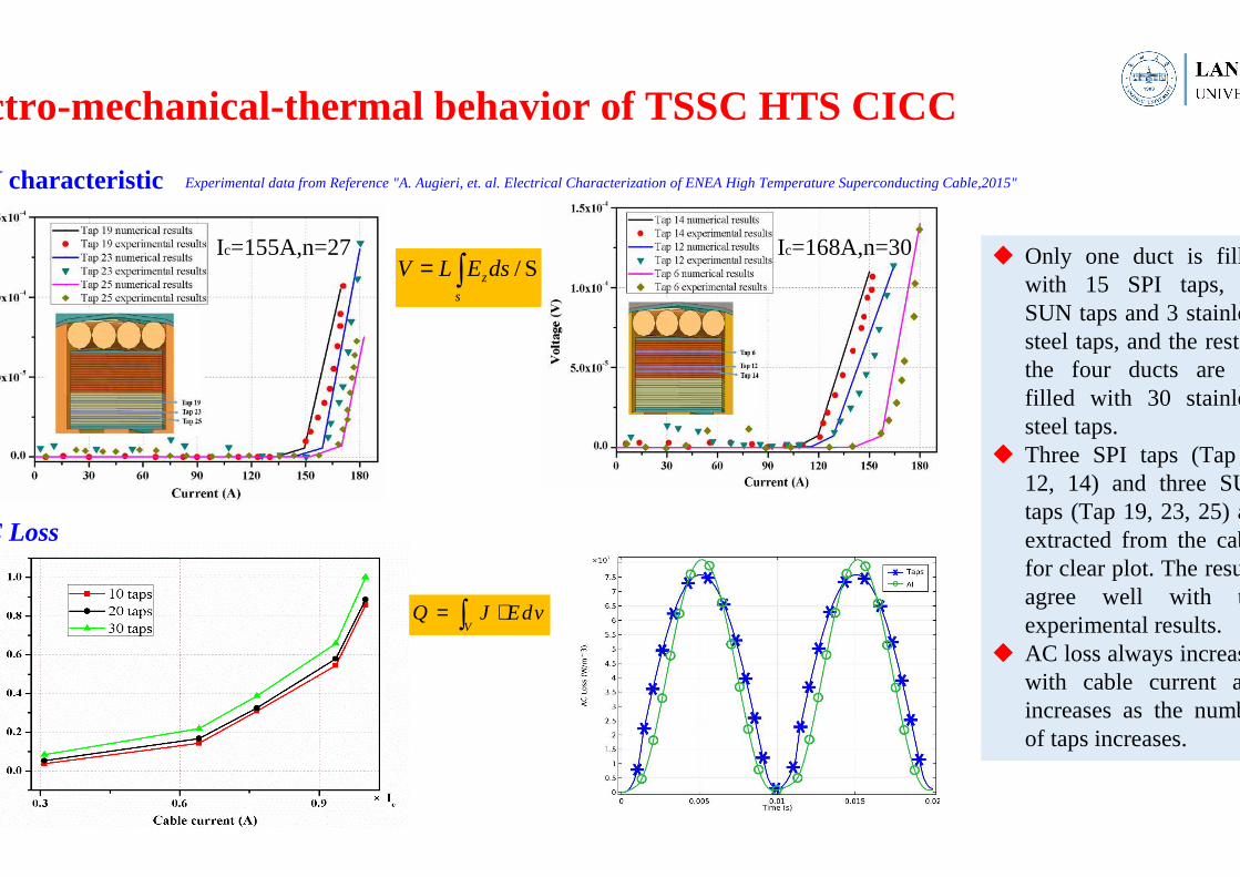
� Only one duct is filled with 15 SPI taps, 12 SUN taps and 3 stainless steel taps, and the rest of the four ducts are all filled with 30 stainless steel taps.
� Three SPI taps (Tap 6, 12, 14) and three SUN taps (Tap 19, 23, 25) are extracted from the cable for clear plot. The results agree well with the experimental results.
� AC loss always increases with cable current and increases as the number of taps increases.
I characteristic
AC Loss
Ic=155A,n=27 Ic=168A,n=30
VQ J Edv= ⋅∫
/ Sz
s
V L E ds= ∫
Electro-mechanical-thermal behavior of TSSC HTS CICC
Experimental data from Reference "A. Augieri, et. al. Electrical Characterization of ENEA High Temperature Superconducting Cable,2015"

Distribution of von Mises stress (color chat) caused by Lorentz force on the middle cross section of cable at different time points
� The maximum stress occurs at the edge of ducts and semicircular grooves due to the stress concentration effect, and the stress in two ends are higher than in middle cross section.
� The stress vary with time, which consistent with the change of the transport current.
Distribution of von Mises stress ((((electromagnetic stress))))
Distribution of von Mises stress caused by Lorentz force in the taps of cable at different time points
Electro-mechanical-thermal behavior of TSSC HTS CICC
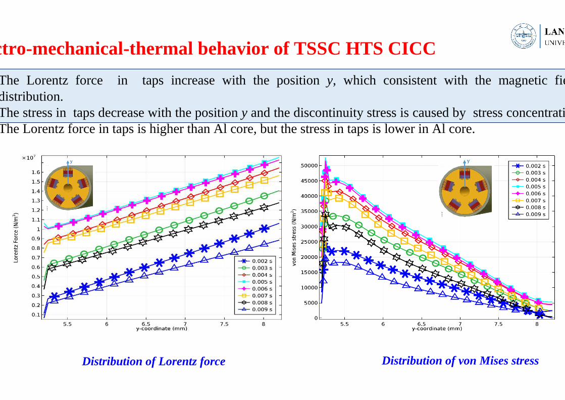
The Lorentz force in taps increase with the positiony, which consistent with the magnetic field distribution.The stress in taps decrease with the position y and the discontinuity stress is caused by stress concentrationThe Lorentz force in taps is higher than Al core, but the stressin taps is lower in Al core.
Distribution of Lorentz force
Electro-mechanical-thermal behavior of TSSC HTS CICC
Distribution of von Mises stress
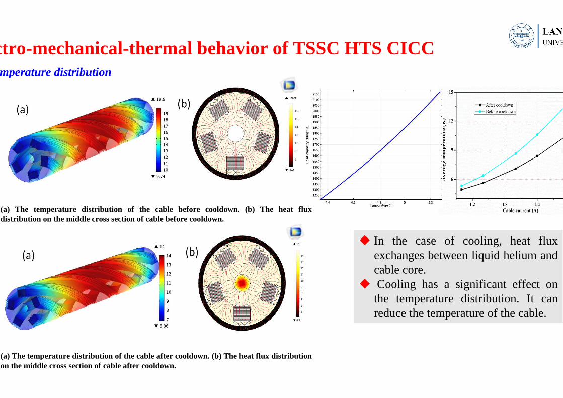
(a) The temperature distribution of the cable before cooldown. (b) The heat flux distribution on the middle cross section of cable before cooldown.
(a) The temperature distribution of the cable after cooldown. (b) The heat flux distribution on the middle cross section of cable after cooldown.
� In the case of cooling, heat flux exchanges between liquid helium and cable core.
� Cooling has a significant effect on the temperature distribution. It can reduce the temperature of the cable.
Temperature distribution
Electro-mechanical-thermal behavior of TSSC HTS CICC
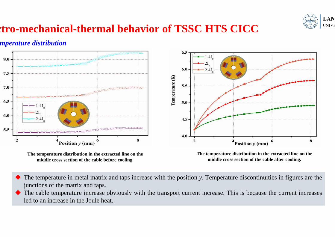
The temperature distribution in the extracted line on the middle cross section of the cable before cooling.
The temperature distribution in the extracted line on the middle cross section of the cable after cooling.
� The temperature in metal matrix and taps increase with the position y. Temperature discontinuities in figures are the junctions of the matrix and taps.
� The cable temperature increase obviously with the transport current increase. This is because the current increases led to an increase in the Joule heat.
Temperature distribution
Electro-mechanical-thermal behavior of TSSC HTS CICC
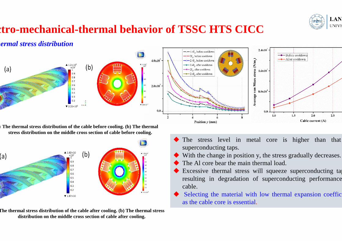
(a) The thermal stress distribution of the cable before cooling. (b) The thermal stress distribution on the middle cross section of cable before cooling.
The thermal stress distribution of the cable after cooling. (b) The thermal stress distribution on the middle cross section of cable after cooling.
� The stress level in metal core is higher than that in superconducting taps.
� With the change in position y, the stress gradually decreases. � The Al core bear the main thermal load. � Excessive thermal stress will squeeze superconducting tapes,
resulting in degradation of superconducting performance of cable.
� Selecting the material with low thermal expansion coefficient as the cable core is essential.
Thermal stress distribution
Electro-mechanical-thermal behavior of TSSC HTS CICC
TSTC cable:
�The profiles of displacement, stress and axial strain of TSTC cable under tension and radial compression are
computed.
�The critical current decreases with increasing load and the plastic deformation makes the degradation more
obvious. the longer of the twist pitch of cable, the smaller the degradation of critical current.
TSSC cable:
�The transport current is non-uniformly distributed among the TSSC cable, and decrease from the top tape in
the stack to the bottom.
�Cooling can reduce the temperature of the cable significantly. the cable temperature and stress increase
obviously with the transport current increase.
�Excessive thermal stress will squeeze superconducting tapes, resulting in degradation of superconducting
performance of cable. So, selecting the material with low thermal expansion coefficient as the cable core and
improving the cooling efficiency are essential.
Conclusions

Thanks for your attention!!!!