electro-mechanical actuators (ema’s) for...
TRANSCRIPT
ELECTRO-MECHANICAL ACTUATORS (EMA’S) FOR SPACE APPLICATIONS
Didier Verhoeven (1), François De Coster (2)
(1) SABCA, 1470 Chaussée de Haecht, B-1130 Brussels (Belgium), [email protected] (2) SABCA, 1470 Chaussée de Haecht, B-1130 Brussels (Belgium), [email protected]
ABSTRACT
The scope of this paper is to present two concepts for electromechanical actuators (EMA’s) for space applications: • The first concept implements external anti-rotation
devices, as well as a blocking device in order to meet the specific Intermediate eXperimental Vehicle (IXV) constraints.
• The second concept is a new anti-rotation device based on DIN 32712-B P4C profile.
1. IXV Flap Control System (FpCS)
The aerospace company SABCA, located at Brussels, Belgium, is in charge of the development and manufacturing of the Flap Control System (FpCS) of the IXV vehicle, under Thales Alenia Space Italy (TAS-I)’s responsibility. The IXV FpCS mainly consists in:
- 2 electro-mechanical actuators (EMA) and levers.
- 1 EMA’s Control Unit (EMACU). - 2 Li-Ion battery modules.
Intermediate Experimental Vehicle (IXV)
Flap Control System (FpCS)
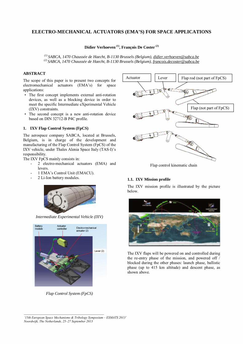
Flap control kinematic chain 1.1. IXV Mission profile
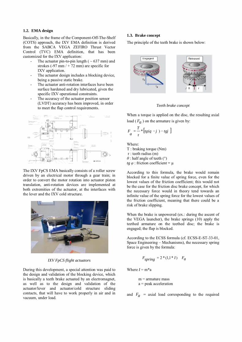
The IXV mission profile is illustrated by the picture below.
The IXV flaps will be powered on and controlled during the re-entry phase of the mission, and powered off / blocked during the other phases: launch phase, ballistic phase (up to 415 km altitude) and descent phase, as shown above.
Actuator Lever Flap rod (not part of FpCS)
Flap (not part of FpCS)
_________________________________________________ ‘15th European Space Mechanisms & Tribology Symposium – ESMATS 2013’ Noordwijk, The Netherlands, 25–27 September 2013
1.2. EMA design
Basically, in the frame of the Component-Off-The-Shelf (COTS) approach, the IXV EMA definition is derived from the SABCA VEGA ZEFIRO Thrust Vector Control (TVC) EMA definition, that has been customized for the IXV application:
- The actuator pin-to-pin length ( ~ 637 mm) and strokes (-97 mm / + 72 mm) are specific for IXV application.
- The actuator design includes a blocking device, being a passive static brake.
- The actuator anti-rotation interfaces have been surface hardened and dry lubricated, given the specific IXV operational constraints.
- The accuracy of the actuator position sensor (LVDT) accuracy has been improved, in order to meet the flap control requirements.
The IXV FpCS EMA basically consists of a roller screw driven by an electrical motor through a gear train; in order to convert the motor rotation into actuator piston translation, anti-rotation devices are implemented at both extremities of the actuator, at the interfaces with the lever and the IXV cold structure.
IXV FpCS flight actuators During this development, a special attention was paid to the design and validation of the blocking device, which is basically a teeth brake actuated by an electromagnet, as well as to the design and validation of the actuator/lever and actuator/cold structure sliding contacts, that will have to work properly in air and in vacuum, under load.
1.3. Brake concept
The principle of the teeth brake is shown below:
Teeth brake concept
When a torque is applied on the disc, the resulting axial load ( aF ) on the armature is given by:
[ ]ϕϕθ tgtgT
aF −−= )(*
r Where: T : braking torque (Nm) r : teeth radius (m) θ : half angle of teeth (°) tg φ : friction coefficient = µ According to this formula, the brake would remain blocked for a finite value of spring force, even for the lowest values of the friction coefficient; this would not be the case for the friction disc brake concept, for which the necessary force would in theory tend towards an infinite value of the spring force for the lowest values of the friction coefficient, meaning that there could be a risk of brake slipping. When the brake is unpowered (ex.: during the ascent of the VEGA launcher), the brake springs (10) apply the teethed armature on the teethed disc; the brake is engaged; the flap is blocked. According to the ECSS formula (cf. ECSS-E-ST-33-01, Space Engineering – Mechanisms), the necessary spring force is given by the formula:
aFIspringF += )*1,1(*2
Where I = m*a m = armature mass a = peak acceleration and aF = axial load corresponding to the required
braking torque (3 Nm)
When the brake is powered by 28Vdc voltage (during the IXV re-entry phase), the electro-magnet compresses the springs, the armature is lifted and the brake is released; the flap is free to move. The necessary electromagnet force is given by the formula:
)*05,1(*2 springFEMF =
The coefficient 1,05 deviates from the ECSS requirement (1,2) (cf. ECSS-E-ST-33-01, Space Engineering – Mechanisms), but can be justified by the fact the springs are individually characterized and sorted before integration into the brake. When the brake is unpowered again (at the end of the IXV re-entry), the brake springs tend to re-apply the armature on the disc; in 77 % of the cases, the teeth are facing each other; under external load on the flap, the mechanism slightly rotates by maximum 10 degrees (corresponding to an actuator displacement of 0,06 mm), and the brake re-engages again (for descent with parachute and splashdown).
The main design characteristics of the brake are summarized below:
Design characteristics Braking torque 7,3 Nm Input power 40 watts Mass 930 g
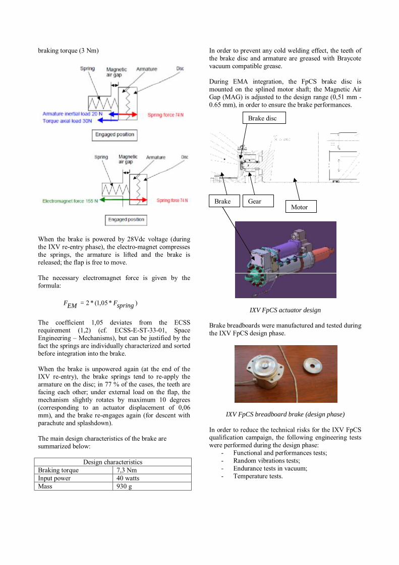
In order to prevent any cold welding effect, the teeth of the brake disc and armature are greased with Braycote vacuum compatible grease. During EMA integration, the FpCS brake disc is mounted on the splined motor shaft; the Magnetic Air Gap (MAG) is adjusted to the design range (0,51 mm - 0.65 mm), in order to ensure the brake performances.
IXV FpCS actuator design Brake breadboards were manufactured and tested during the IXV FpCS design phase.
IXV FpCS breadboard brake (design phase) In order to reduce the technical risks for the IXV FpCS qualification campaign, the following engineering tests were performed during the design phase:
- Functional and performances tests; - Random vibrations tests; - Endurance tests in vacuum; - Temperature tests.
Motor Brake Gear
Brake disc

1.4. Anti-rotation concept
Both extremities of the EMA are equipped with anti-rotation bossles, as shown by the pictures below.
Piston bossle
Rod end bossle
In order to meet the specific IXV operational and environmental constraints:
- The bossles surfaces are hardened and dry lubricated.
- The sliding surfaces are greased with Braycote vacuum compatible grease.
- The clearance between the bossles and the adjacent parts is adjusted during the actuator integration.
The concept was validated through:
- Functional and duty cycle tests with the breadboard EMA.
- Pin-on-discs tests, in air and in vacuum, under representative load, that were performed at the European Space Tribology Laboratory (ESTL/ESR-T).
1.5. Summary
The IXV FpCS electro-mechanical actuators (EMA’s) are based on VEGA ZEFIRO TVC EMA’s design (COTS approach), and were customized in order to meet the IXV mission constraints; the main technological changes being:
- the implementation of a passive static brake; - the implementation of a more accurate position
sensor (LVDT); - the implementation of anti-rotation bossles
with specific surface hardening and lubrication. Those technological changes were validated by engineering, breadboard and/or pin-on-discs tests, in order to reduce the technical risks during the qualification campaign.
2. Compact anti-rotation device for space EMA
2.1. EMA constraints
IXV anti-rotation is realised through bossles at both fixation interfaces of the actuator. This implies that the torque is transmitted to both the vehicle structure and the flap lever, which need to be hardened and protected as well as the actuator. Actuators for launcher first stage do not work in vacuum and tribology does not cause a high wear. However, actuators for upper stage or for re-entry systems are working up to several hours in vacuum, which increases significantly the wear problem. In some cases, torque transmission is not allowed when fairing wear would be inacceptable or when fairing hardening is not possible. The environment constraints used for the design are the following:
- Temperature range: -30°C to +75°C - Pressure: 1E-4 mbar to 1 bar
2.2. Proposed anti-rotation concept
2.2.1. Introduction
As an alternative to IXV design, SABCA has developed a new anti-rotation device based on DIN 32712-B P4C profile (see figure below).
Tested actuator piston and its anti-rotation bearing
using DIN 32712-B P4C profile This profile was specifically designed for industrial applications needing a high torque transmission on sliding components. Tribologic performances of that profile in vacuum have been carefully analysed by SABCA.
2.2.2. Selection of materials
Classically, pistons are made of steel and bearings are made of bronze.
However, P4C profile specifies a very tight gap to work nominally, which is not compatible with 2 materials having different dilatation coefficients working on a wide temperature range.
An alternative to this is to increase the gap between piston and P4C bearing beyond the DIN specification. Another solution is to use a steel piston with a steel P4C bearing.
Both solutions have been tested.
2.2.3. Coating selection
The use of both piston and P4C bearing in steel requires a coating on at least the piston.
DLC (Diamond Like Carbon) coating is often used in industrial applications using P4C. According to datasheets, lubrication is not necessary with that coating, at least in atmospheric conditions. We have decided to test that coating.
Balinit C™ is used at SABCA for a space EMA, but in conjunction with chromium deposit. Carbon lubrication effect is very poor in vacuum. So, that coating has been rejected.
Finally, we have decided to also test the MoS2 coating, which is reputed for its good tribologic characteristics for space applications.
2.2.4. Lubrication selection
DLC coating does not require lubrication in industrial applications and a test has been performed to evaluate this behaviour in vacuum.
For other tested coatings, Braycote lubricant has been selected because of:
- Compatibility with vacuum - High contact pressure - Resistance to Oxygen
2.3. Test philosophy
The anti-rotation device has been assembled on an existing EMA (see figure below) in order to control the piston displacement.
Tested EMA with bronze P4C bearing
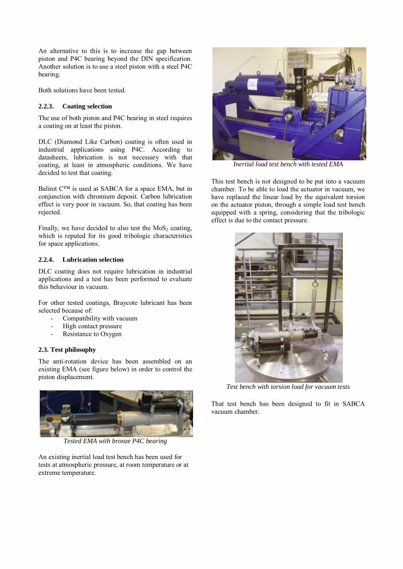
An existing inertial load test bench has been used for tests at atmospheric pressure, at room temperature or at extreme temperature.
Inertial load test bench with tested EMA
This test bench is not designed to be put into a vacuum chamber. To be able to load the actuator in vacuum, we have replaced the linear load by the equivalent torsion on the actuator piston, through a simple load test bench equipped with a spring, considering that the tribologic effect is due to the contact pressure.
Test bench with torsion load for vacuum tests
That test bench has been designed to fit in SABCA vacuum chamber.
SABCA vacuum chamber
The test sequence is the following, with a no-load health test after every test:
• Thermal test for reference piston (without anti-rotation)
• For every P4C configuration: o Thermal test with load o Vacuum test with load o Endurance test (for last configuration only)
• Thermal test for reference piston (without anti-rotation)
The test with a reference piston without anti-rotation is performed to identify the friction due to the anti-rotation and the friction due to the other parts of the actuators. Each test consists in series of triangles at various velocities from 0.1 mm/s to 100 mm/s to evaluate the behaviour of the anti-rotation at different velocities.
During the tests, the following variables are recorded:
- EMA position - EMA velocity - EMA current (image of the torque)
The evolution of the measured current allows us to evaluate the evolution of friction, hence the behaviour of the antirotation.
2.4. Test campaign
The test campaign has compared the following configurations:
1. DLC coated piston with uncoated steel P4C bearing
2. DLC coated piston with DLC coated steel P4C bearing, greased
3. DLC coated piston with bronze P4C bearing, greased
4. MoS2 coated piston with MoS2 coated P4C bearing, greased
2.4.1. Uncoated steel P4C bearing
The first configuration is the simpler and cheaper one but it is also the most risky. Anyway, in order to minimise the cost of the solution, it was worth to test it. The result was that the coating experienced a fast wear and jamming occurred when the coating was removed after a few cycles in vacuum with high loads.
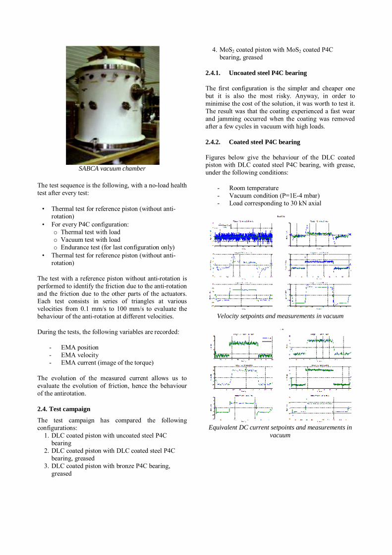
2.4.2. Coated steel P4C bearing
Figures below give the behaviour of the DLC coated piston with DLC coated steel P4C bearing, with grease, under the following conditions:
- Room temperature - Vacuum condition (P=1E-4 mbar) - Load corresponding to 30 kN axial
Velocity setpoints and measurements in vacuum
Equivalent DC current setpoints and measurements in
vacuum

Comparison of the average motor torque for different
load torques at atmospheric pressure (left) and in vacuum (right)
No significant increase of the torque is observed during the vacuum test, confirming the good behaviour of the solution.
Next figures show the piston and its bearing after the vacuum test. A significant wear is visible at the place of contact of the piston with the bearing, which is caused by a too small hardness of the stainless steel used for the test.
Piston with coating after thermal test with seal retainer
coated
P4C bearing with coating after vacuum tests
Thermal behaviour has also been tested. Plot below gives the evolution of the anti-rotation with temperature for different velocities in both displacement directions: with antagonist and motor load. Due to increase of
grease viscosity, the torque need increases at low temperature.
Average torque on motor axis for different temperatures
2.4.3. Bronze P4C bearing
Similar tests have been performed with the bronze bearing. No significant increase of the torque was observed during the vacuum test, confirming the good behaviour of the solution.
Next figures show the bearing after the vacuum test. A slight wear is visible at the place of contact of the piston with the bearing, as foreseen.
Due to the larger gap between piston and bearing to cope with thermal dilatation, the contact place is at the extremity of the profile (compare wear on steel bearing and on bronze bearing).
Bronze P4C bearing (after vacuum tests)
Thermal behaviour has also been tested. The observed behaviour is the same as with the previous solution. No jamming due to thermal dilatation or deformation has appeared, nor unexpected increase of friction.
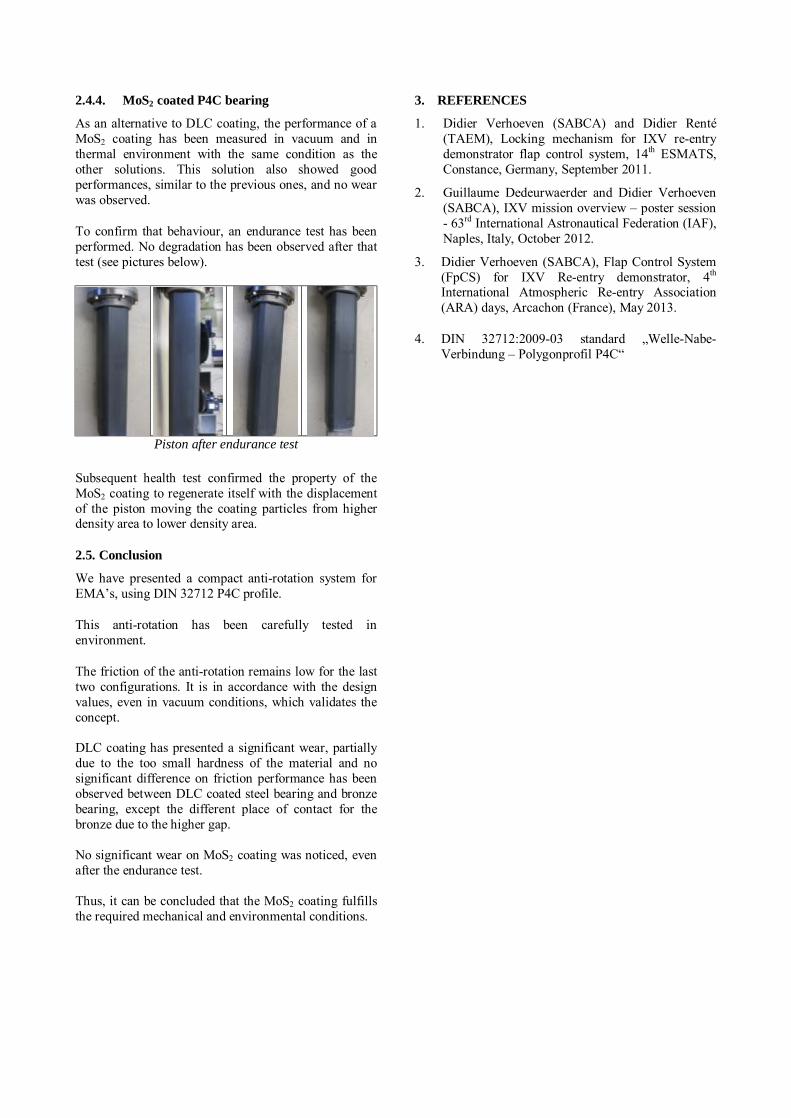
2.4.4. MoS2 coated P4C bearing
As an alternative to DLC coating, the performance of a MoS2 coating has been measured in vacuum and in thermal environment with the same condition as the other solutions. This solution also showed good performances, similar to the previous ones, and no wear was observed.
To confirm that behaviour, an endurance test has been performed. No degradation has been observed after that test (see pictures below).
Piston after endurance test
Subsequent health test confirmed the property of the MoS2 coating to regenerate itself with the displacement of the piston moving the coating particles from higher density area to lower density area.
2.5. Conclusion
We have presented a compact anti-rotation system for EMA’s, using DIN 32712 P4C profile.
This anti-rotation has been carefully tested in environment.
The friction of the anti-rotation remains low for the last two configurations. It is in accordance with the design values, even in vacuum conditions, which validates the concept. DLC coating has presented a significant wear, partially due to the too small hardness of the material and no significant difference on friction performance has been observed between DLC coated steel bearing and bronze bearing, except the different place of contact for the bronze due to the higher gap. No significant wear on MoS2 coating was noticed, even after the endurance test. Thus, it can be concluded that the MoS2 coating fulfills the required mechanical and environmental conditions.
3. REFERENCES
1. Didier Verhoeven (SABCA) and Didier Renté (TAEM), Locking mechanism for IXV re-entry demonstrator flap control system, 14th ESMATS, Constance, Germany, September 2011.
2. Guillaume Dedeurwaerder and Didier Verhoeven (SABCA), IXV mission overview – poster session - 63rd International Astronautical Federation (IAF), Naples, Italy, October 2012.
3. Didier Verhoeven (SABCA), Flap Control System (FpCS) for IXV Re-entry demonstrator, 4th International Atmospheric Re-entry Association (ARA) days, Arcachon (France), May 2013.
4. DIN 32712:2009-03 standard „Welle-Nabe-Verbindung – Polygonprofil P4C“