electricity in buildings cibse code k
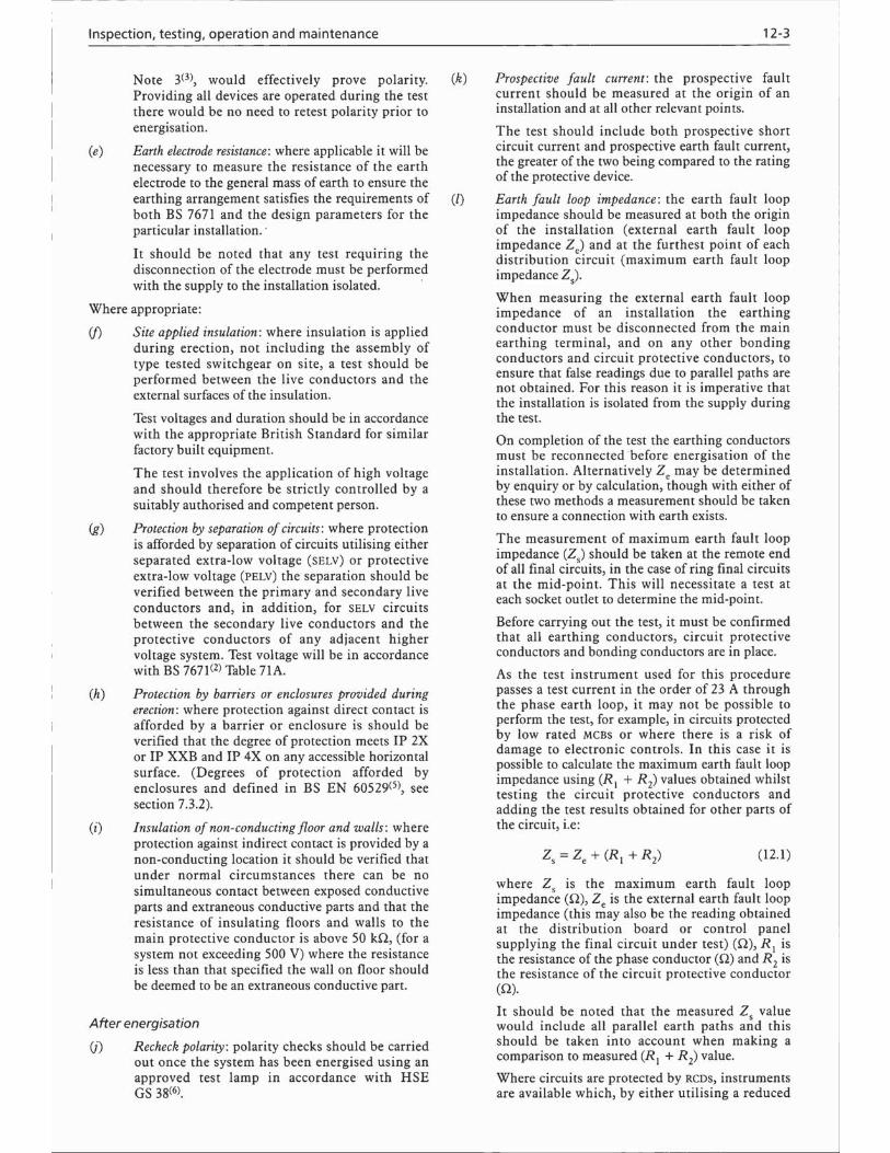
DESCRIPTION
Electrical EngineeringTRANSCRIPT


CIBSE AMENDMENT
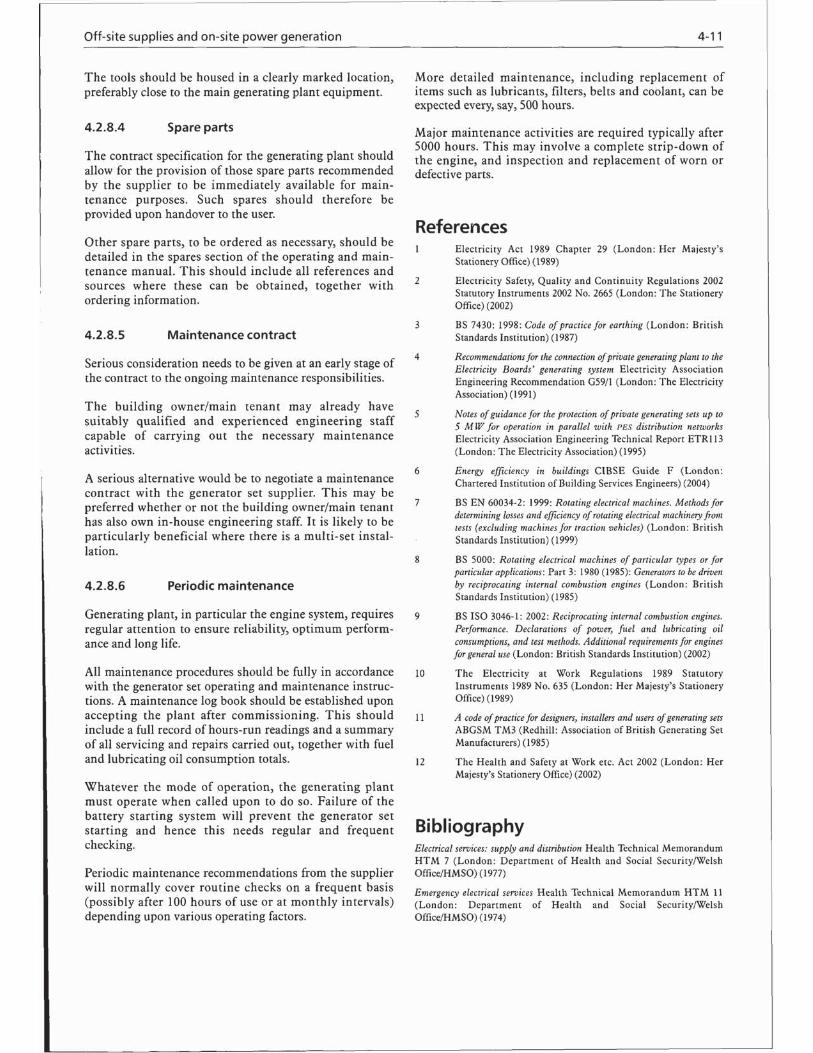
Guide K: Electricity in Buildings
Page 8-3, Figure 8.3: Caption should read:
“Basic radial final circuits; ?”
August 2005

Page 3-1: the following replaces equation 3.1:
P = Uo I cos φ (3.1)
where P is the active power (W), Uo is the phase-to-neutralvoltage (V), I is the current (A), φ is the angulardisplacement between the voltage and current waveformsand is known as the power factor angle; cos φ is known asthe power factor.
Page 3-1: the following replaces equation 3.2:
P = √3 U I cos φ (3.2)
where U is the line (i.e. phase-to-phase) voltage (V).
Page 3-1: the following replaces equations 3.3 and 3.4:
For single-phase:
S = Uo I × 10–3 (3.3)
For three-phase:
S = √3 U I × 10–3 (3.4)
where S is the apparent power (kV·A).
Page 4-6: the following replaces equation 4.1 (wrongly numbered3.1 in the Guide):
Sa = √3 U Il × 10–3 (4.1)
where Sa is the rated kV·A of the alternator (kV·A), U is theline (i.e. phase-to-phase) voltage (V), and Il is the rated fullload line current (A).
Page 5-1: the following replaces equation 5.1:
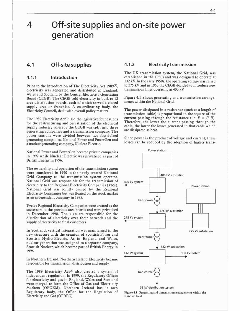
PL = I2 Rc (5.1)
where PL is the power loss (W), I is the current carried inthe cable (A) and Rc is the resistance of the cable (�). Byincreasing the voltage and, hence, reducing the current, thepower loss is reduced and the transmission efficiencyimproved.
Page 5-10: the following replaces equation 5.4:
KVAb Z lCable impedance (%) = ———— × 105 (5.4)
V 2
where KVAb is the base kV·A value (kV·A), Z is the imped-ance per unit length of the cable (�·m–1), l is the length of thecable (m) and V is the line (i.e. phase-to-phase) voltage (V).
Page 5-10: the following replaces equation 4.1:
MVAf × 103
Isc = ———–— (5.7)√3 V
Page 5-10: Example: fault level calculation: the followingreplaces the last equation in the example:
Hence, the maximum short circuit current is:
14.01 × 10³
Isc = ———–—– = 20.22 kA√3 × 400
Page 5-11: equation 5.8 is wrongly numbered 5.9 in the Guide;replace by:
HV fuse current LV device operation < ——————– (5.8)
0.05
Page 6-1: the following replaces equation 6.1:
S = Uo I × 10–3 (6.1)
where S is the full load power (kV·A), Uo is the ratedseondary (phase-to-neutral) voltage (V) and I is the ratedoutput current (A).
Page 6-2: the following replaces equations 6.2 to 6.6 and theaccompanying text:
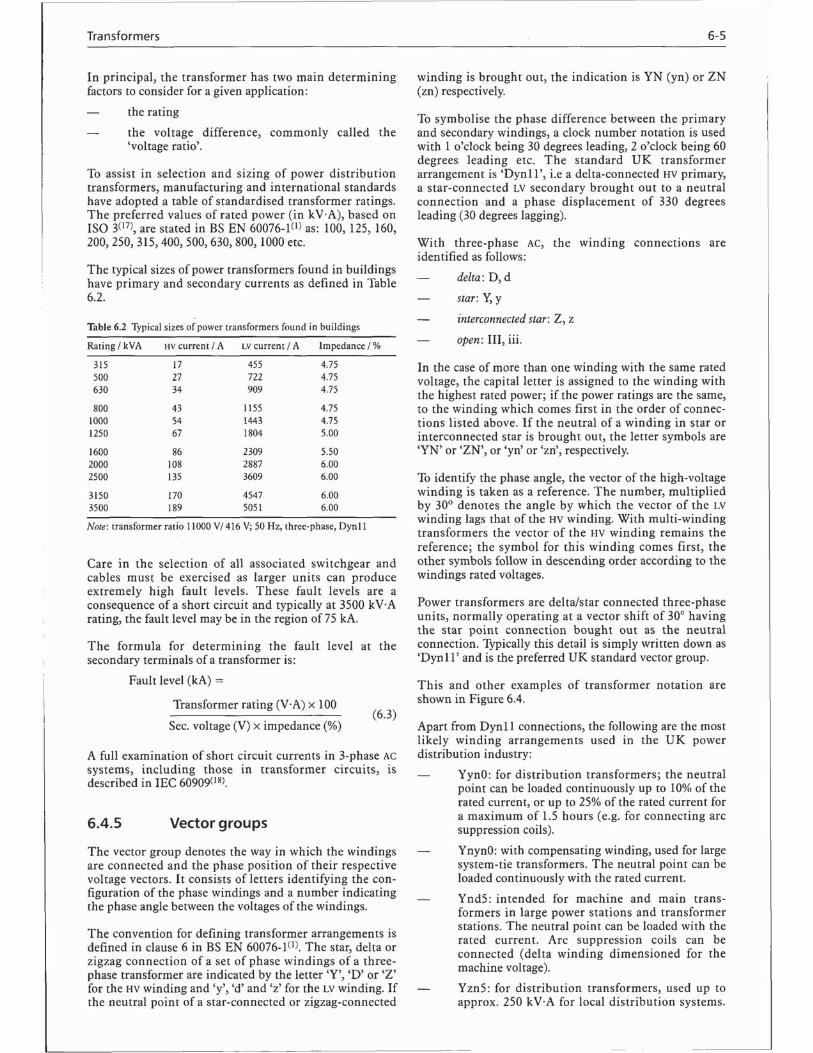
For three-phase transformers, this is expressed as:
S = √3 U I × 10–3 (6.2)
The values for voltage and current in star- and delta-connected three-phase windings are as follows.
For star connection:
UPhase-to-neutral voltage = Uo = —— (6.3)
√3
For delta connection:
Phase voltage = line voltage = U = √3 Uo (6.4)
The output current of the transformer in both cases isequal to:
S × 103
I = ——–– (6.5)3 Uo
or:
S × 103
I = ——— (6.6)√3 U
Jan 2006
CIBSE Guide K: corrigenda GK01-1
Page 6-5: the following replaces equation 6.7 (wrongly numbered6.3 in the Guide):
3-phase trans. rating (kV·A) × 100Fault level (kA) = —————————––———––— (6.7)
√3 Uo × impedance (%)
where U is the secondary line (phase-to-phase) voltage (V).
Page 8-3: the following replaces the caption to Figure 8.3:
Figure 8.3 Basic radial final circuit; typical UK practice (Note: cable
colours will change from 2006, see section 8.4.1.4)
Page 10-3: in Figures 10.3(a) and 10.3(b), Uo should bereplaced by Uoc.
Page 10-3: the following replaces the caption to Figure 10.3:
Figure 10.3 Definition of earth loop impedance(9); (a) TN system,
(b) TT system (Uoc is the no-load open circuit phase-to-earthed-neutral
voltage measured at the terminals of the transformer)
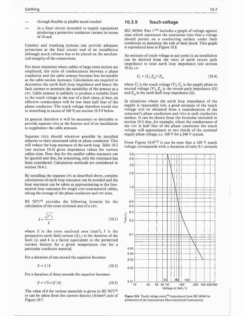
Page 10-7: the following replaces equation 10.4:
Ut = (Uoc Zp) / Zel (10.4)
where Ut is the touch voltage (V), Uoc is the no-load opencircuit supply phase-to-earthed-neutral voltage (V), Zp isthe return path impedance (�) and Zel is the earth faultloop impedance (�).
Page 10-9: the following replaces equation 10.5:
If = Uoc / Zel (10.5)
where If is the earth fault current (A), Uoc is the no-loadopen circuit supply phase-to-earthed-neutral voltage (V)and Zel is the earth loop impedance (�).
Page 10-10: in Figures 10.11 and 10.12, Uo should bereplaced by Uoc.
Page 10-10: the following replaces equation 10.13:
Σ (Zp + Zpo)Ut = Uoc —————– (10.13)
Zel
where Uoc is the no-load open circuit phase-to-earthed-neutral voltage (V).
Page 10-10: the following replaces equation 10.14:
Σ ZpUt = Uoc —— (10.14)Zel
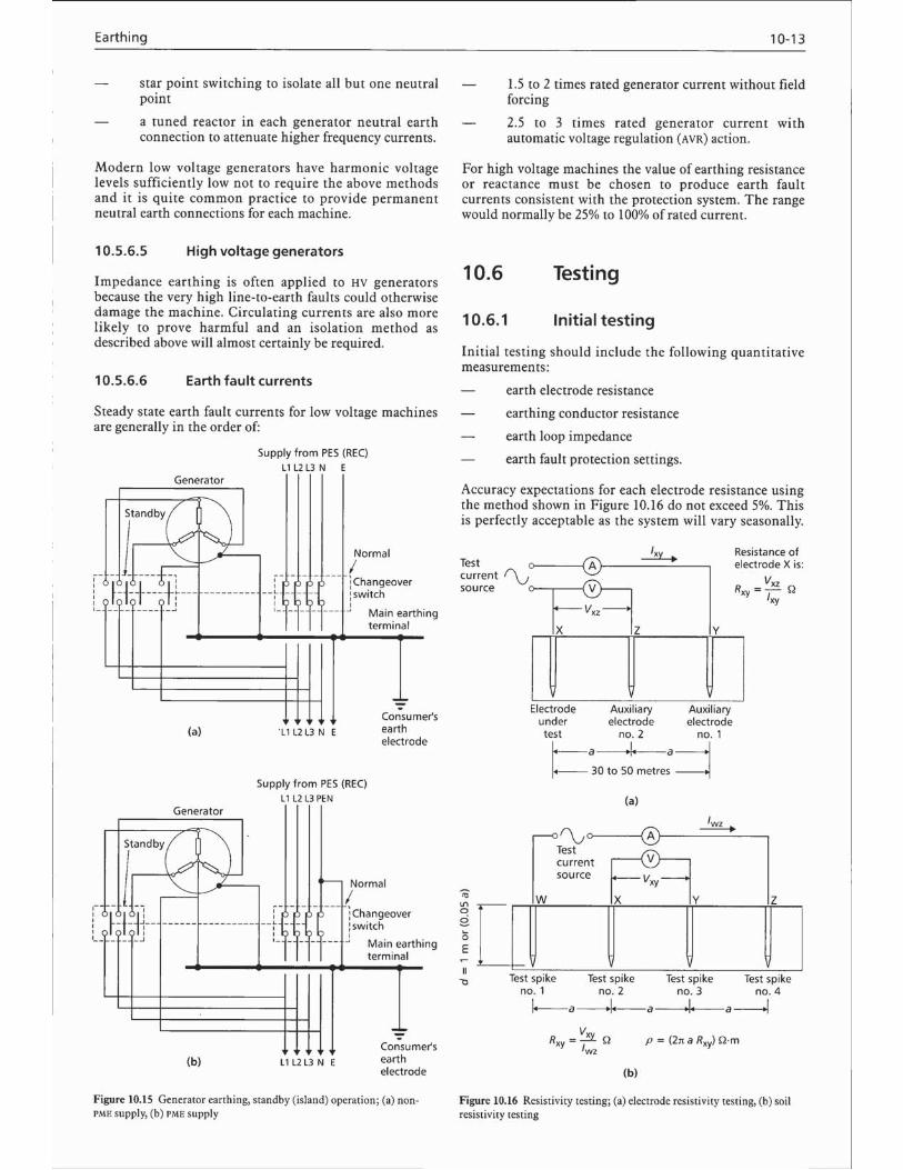
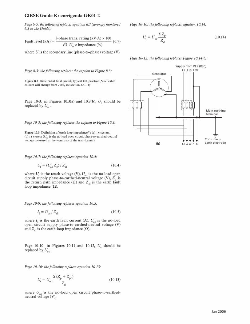
Page 10-12: the following replaces Figure 10.14(b):
Main earthingterminal
Consumer'searth electrode
Generator
Supply from PES (REC)L1 L2 L3
L1 L2 L3 N E(b)
PEN
Jan 2006
CIBSE Guide K: corrigenda GK01-2