electricity and new energy labvolt series student manual€¦ · festo didactic single-phase...
TRANSCRIPT

Single-Phase Induction Motors
Electricity and New Energy
LabVolt Series
Student Manual
579474
en
Festo Didactic
Single-Phase Induction Motors
Student Manual
www.festo-didactic.com
Germany
Festo Didactic SE
Rechbergstr. 3
73770 Denkendorf
Tel.: +49 711 3467-0Fax: +49 711 347-54-88500
United States
Festo Didactic Inc.
607 Industrial Way WestEatontown, NJ 07724
Tel.: +1 732 938-2000
Toll Free: +1-800-522-8658
Fax: +1 732 [email protected]
CanadaFesto Didactic Ltée/Ltd
675, rue du Carbone
Québec (Québec) G2N 2K7
Tel.: +1 418 849-1000Toll Free: +1-800-522-8658
Fax: +1 418 849-1666
0000
5794
7400
0000
0001
00

Electricity and New Energy
Single-Phase Induction Motors
Student Manual 579474

Order no.: 579474
First Edition
Revision level: 07/2016
By the staff of Festo Didactic
© Festo Didactic Ltée/Ltd, Quebec, Canada 2013
Internet: www.festo-didactic.com
e-mail: [email protected]
Printed in Canada
All rights reserved
ISBN 978-2-89640-628-9 (Printed version)
ISBN 978-2-89640-629-6 (CD-ROM)
Legal Deposit – Bibliothèque et Archives nationales du Québec, 2013
Legal Deposit – Library and Archives Canada, 2013
The purchaser shall receive a single right of use which is non-exclusive, non-time-limited and limited
geographically to use at the purchaser's site/location as follows.
The purchaser shall be entitled to use the work to train his/her staff at the purchaser’s site/location and
shall also be entitled to use parts of the copyright material as the basis for the production of his/her own
training documentation for the training of his/her staff at the purchaser’s site/location with
acknowledgement of source and to make copies for this purpose. In the case of schools/technical
colleges, training centers, and universities, the right of use shall also include use by school and college
students and trainees at the purchaser’s site/location for teaching purposes.
The right of use shall in all cases exclude the right to publish the copyright material or to make this
available for use on intranet, Internet and LMS platforms and databases such as Moodle, which allow
access by a wide variety of users, including those outside of the purchaser’s site/location.
Entitlement to other rights relating to reproductions, copies, adaptations, translations, microfilming and
transfer to and storage and processing in electronic systems, no matter whether in whole or in part, shall
require the prior consent of Festo Didactic.
Information in this document is subject to change without notice and does not represent a commitment on
the part of Festo Didactic. The Festo materials described in this document are furnished under a license
agreement or a nondisclosure agreement.
Festo Didactic recognizes product names as trademarks or registered trademarks of their respective
holders.
All other trademarks are the property of their respective owners. Other trademarks and trade names may
be used in this document to refer to either the entity claiming the marks and names or their products.
Festo Didactic disclaims any proprietary interest in trademarks and trade names other than its own.

© Festo Didactic 579474 III
Safety and Common Symbols
The following safety and common symbols may be used in this manual and on the equipment:
Symbol Description
DANGER indicates a hazard with a high level of risk which, if not avoided, will result in death or serious injury.
WARNING indicates a hazard with a medium level of risk which, if not avoided, could result in death or serious injury.
CAUTION indicates a hazard with a low level of risk which, if not avoided, could result in minor or moderate injury.
CAUTION used without the Caution, risk of danger sign , indicates a hazard with a potentially hazardous situation which, if not avoided, may result in property damage.
Caution, risk of electric shock
Caution, hot surface
Caution, risk of danger
Caution, lifting hazard
Caution, hand entanglement hazard
Notice, non-ionizing radiation
Direct current
Alternating current
Both direct and alternating current
Three-phase alternating current
Earth (ground) terminal

Safety and Common Symbols
IV © Festo Didactic 579474
Symbol Description
Protective conductor terminal
Frame or chassis terminal
Equipotentiality
On (supply)
Off (supply)
Equipment protected throughout by double insulation or reinforced insulation
In position of a bi-stable push control
Out position of a bi-stable push control

© Festo Didactic 579474 V
Table of Contents
Preface ................................................................................................................. VII
About This Manual ................................................................................................ IX
Introduction AC Induction Motors .................................................................... 1
DISCUSSION OF FUNDAMENTALS ....................................................... 1 Introduction to ac induction motors.......................................... 1
Exercise 1 Operation and Characteristics of Single-Phase Induction Motors ........................................................................................... 5
DISCUSSION ..................................................................................... 5 Simple single-phase squirrel-cage induction motor ................. 5 Adding a capacitor and an auxiliary winding to the single-phase induction motor ............................................................. 7 Centrifugal switch .................................................................... 9
PROCEDURE .................................................................................. 10 Set up and connections ......................................................... 10 Three-phase, two-phase, and single-phase operation of a three-phase squirrel-cage induction motor ............................ 11 Operation of a single-phase induction motor (split-phase and capacitor-start types) ...................................................... 14
Appendix A Equipment Utilization Chart ...................................................... 21
Appendix B Glossary of New Terms ............................................................. 23
Appendix C Circuit Diagram Symbols .......................................................... 25
Index of New Terms ............................................................................................. 31
Bibliography ......................................................................................................... 33


© Festo Didactic 579474 VII
Preface
The production of energy using renewable natural resources such as wind, sunlight, rain, tides, geothermal heat, etc., has gained much importance in recent years as it is an effective means of reducing greenhouse gas (GHG) emissions. The need for innovative technologies to make the grid smarter has recently emerged as a major trend, as the increase in electrical power demand observed worldwide makes it harder for the actual grid in many countries to keep up with demand. Furthermore, electric vehicles (from bicycles to cars) are developed and marketed with more and more success in many countries all over the world.
To answer the increasingly diversified needs for training in the wide field of electrical energy, the Electric Power Technology Training Program was developed as a modular study program for technical institutes, colleges, and universities. The program is shown below as a flow chart, with each box in the flow chart representing a course.
The Electric Power Technology Training Program.

Preface
VIII © Festo Didactic 579474
The program starts with a variety of courses providing in-depth coverage of basic topics related to the field of electrical energy such as ac and dc power circuits, power transformers, rotating machines, ac power transmission lines, and power electronics. The program then builds on the knowledge gained by the student through these basic courses to provide training in more advanced subjects such as home energy production from renewable resources (wind and sunlight), large-scale electricity production from hydropower, large-scale electricity production from wind power (doubly-fed induction generator [DFIG], synchronous generator, and asynchronous generator technologies), smart-grid technologies (SVC, STATCOM, HVDC transmission, etc.), storage of electrical energy in batteries, and drive systems for small electric vehicles and cars.
We invite readers of this manual to send us their tips, feedback, and suggestions for improving the book.
Please send these to [email protected].
The authors and Festo Didactic look forward to your comments.

© Festo Didactic 579474 IX
About This Manual
The present manual, Single-Phase Induction Motors, introduces the student to the operation and characteristics of the following two types of single-phase induction motor: capacitor-start induction motor and split-phase induction motor. These motors, although still in use in numerous applications today, are less common in modern applications where they are often replaced with three-phase induction motor drives (i.e., a three-phase squirrel-cage induction motor plus a variable-frequency, three-phase inverter) for added flexibility of operation and improved performance.
Safety considerations
Safety symbols that may be used in this manual and on the equipment are listed in the Safety Symbols table at the beginning of the manual.
Safety procedures related to the tasks that you will be asked to perform are indicated in each exercise.
Make sure that you are wearing appropriate protective equipment when performing the tasks. You should never perform a task if you have any reason to think that a manipulation could be dangerous for you or your teammates.
Prerequisite
As a prerequisite to this course, you should have read the manuals titled DC Power Circuits, part number 86350 and Single-Phase AC power Circuits, part number 86358.
Systems of units
Units are expressed using the International System of Units (SI) followed by units expressed in the U.S. customary system of units (between parentheses).


© Festo Didactic 579474 1
When you have completed this manual, you will be able to demonstrate the main operating characteristics of single-phase induction motors.
The Discussion of Fundamentals covers the following points:
Introduction to ac induction motors
Introduction to ac induction motors
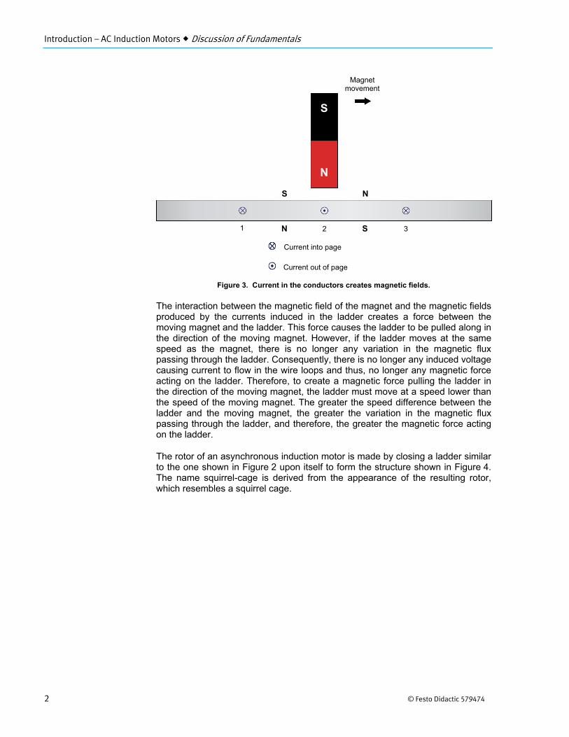
According to Faraday's law of electromagnetic induction, a voltage is induced between the ends of a wire loop when the magnetic flux passing through the loop varies as a function of time. If the ends of the wire loop are short-circuited together, a current flows in the loop. Figure 2 shows a magnet that is displaced rapidly toward the right above a group of conductors. The conductors are short-circuited at their extremities by bars A and B and form a structure similar to a ladder.
Figure 2. Magnet moving above a conducting ladder.
Current flows in the loop formed by conductors 1 and 2, as well as in the loop formed by conductors 2 and 3. These currents create magnetic fields having north and south poles, as Figure 3 shows.
AC Induction Motors
Introduction
MANUAL OBJECTIVE
DISCUSSION OUTLINE
DISCUSSION OF
FUNDAMENTALS
Figure 1. The principles behind the operation of alternating-current motors are usually credited to sci-entist Nikola Tesla.
Magnet movement
N
S
1 2 3
Bar A
Bar B
Introduction – AC Induction Motors Discussion of Fundamentals
2 © Festo Didactic 579474
Figure 3. Current in the conductors creates magnetic fields.
The interaction between the magnetic field of the magnet and the magnetic fields produced by the currents induced in the ladder creates a force between the moving magnet and the ladder. This force causes the ladder to be pulled along in the direction of the moving magnet. However, if the ladder moves at the same speed as the magnet, there is no longer any variation in the magnetic flux passing through the ladder. Consequently, there is no longer any induced voltage causing current to flow in the wire loops and thus, no longer any magnetic force acting on the ladder. Therefore, to create a magnetic force pulling the ladder in the direction of the moving magnet, the ladder must move at a speed lower than the speed of the moving magnet. The greater the speed difference between the ladder and the moving magnet, the greater the variation in the magnetic flux passing through the ladder, and therefore, the greater the magnetic force acting on the ladder.
The rotor of an asynchronous induction motor is made by closing a ladder similar to the one shown in Figure 2 upon itself to form the structure shown in Figure 4. The name squirrel-cage is derived from the appearance of the resulting rotor, which resembles a squirrel cage.
Magnet movement
N
S
1 2 3
S N
N S
Current into page
Current out of page

Introduction – AC Induction Motors Discussion of Fundamentals
© Festo Didactic 579474 3
Figure 4. Closing a ladder upon itself forms a squirrel cage.
To make it easier for the magnetic flux to circulate, the rotor of a three-phase squirrel-cage induction machine is placed inside a laminated iron cylinder. The stator of the three-phase squirrel-cage induction machine acts as a rotating electromagnet. The rotating electromagnet produces a torque which pulls the rotor along in much the same manner as the moving magnet in Figure 2 pulls the ladder.


© Festo Didactic 579474 5
When you have completed this exercise, you will be able to demonstrate the main operating characteristics of single-phase induction motors. You will start by studying what happens when a three-phase squirrel-cage induction motor is powered by the three phases, two phases, and one phase of the three-phase ac power source. You will know how to connect a capacitor and an auxiliary winding to a single-phase induction motor to allow this motor to start and rotate normally. You will also know how to create a starting torque by adding an auxiliary winding having an impedance that differs from that of the main winding. Finally, you will know how to use a centrifugal switch to disconnect the auxiliary winding and capacitor of a single-phase induction motor once the motor starts rotating.
The Discussion of this exercise covers the following points:
Simple single-phase squirrel-cage induction motor Adding a capacitor and an auxiliary winding to the single-phase induction
motor Centrifugal switch
Simple single-phase squirrel-cage induction motor
It is possible to obtain a single-phase squirrel-cage induction motor, using a simple electromagnet connected to a single-phase ac power source as shown in Figure 5.
Figure 5. Simple single-phase squirrel-cage induction motor.
Operation and Characteristics of Single-Phase Induction Motors
Exercise 1
EXERCISE OBJECTIVE
DISCUSSION OUTLINE
DISCUSSION
Electromagnet used as stator
Squirrel-cage rotor AC power source

Exercise 1 – Operation and Characteristics of Single-Phase Induction Motors Discussion
6 © Festo Didactic 579474
The operating principle of the single-phase induction motor is more complex than that of the three-phase squirrel-cage induction motor. The simple single-phase induction motor of Figure 5 can even be considered as an eddy-current brake that brakes in an intermittent manner since the sinusoidal current in the stator electromagnet continually passes from peaks to zeros. One could even wonder how this motor can turn since it seems to operate in a way similar to the eddy-current brake.
However, when the rotor of the simple single-phase induction motor of Figure 5 is turned manually, a torque which acts in the direction of rotation is produced, and the motor continues to turn as long as ac power is supplied to the stator electromagnet. This torque is due to a rotating magnetic field that results from the interaction of the magnetic field produced by the stator electromagnet and the magnetic field produced by the currents induced in the rotor. Figure 6 shows a graph of the torque versus rotation speed for this type of motor. The curve shows that the torque is very small at low speeds. It increases to a maximum value as the speed increases, and finally decreases toward zero again when the speed approaches the synchronous speed .
Figure 6. Torque-versus-rotation speed curve of a single-phase induction motor.
The low torque values at low speeds are due to the fact that the currents induced in the rotor produce magnetic fields that create forces which act on the rotor in various directions. Most of these forces cancel each other and the resulting force acting on the rotor is weak. This explains why the single-phase induction motor shown in Figure 5 must be started manually. To obtain torque at low speeds (starting torque), a rotating magnetic field must be produced in the stator when the motor is starting. A rotating magnetic field can be produced by using two alternating currents, and , that are phase shifted 90° from one another, and two electromagnets placed at right angles to each other.
Figure 7 shows the simple single-phase induction motor of Figure 5 with the addition of a second electromagnet placed at right angle to the first electromagnet. The second electromagnet is identical to the first one and is connected to the same ac power source. The currents and in the electromagnets (winding currents) are in phase because the coils have the same impedance. However, because of the inductance of the coils of the electromagnets, there is a phase shift between the currents and and the ac source voltage , as shown in the phasor diagram of Figure 7.
Motor rotation speed n (r/min)
Mot
or to
rque
T(
N·m
or
lbf·
in)

Exercise 1 – Operation and Characteristics of Single-Phase Induction Motors Discussion
© Festo Didactic 579474 7
Figure 7. Adding a second electromagnet to the single-phase induction motor of Figure 5.
Adding a capacitor and an auxiliary winding to the single-phase induction motor
Since currents and in the electromagnets (winding currents) of Figure 7 are in phase, there is no rotating magnetic field produced in the motor stator. However, it is possible to phase shift current by connecting a capacitor ( ) in series with the winding of electromagnet 2 as shown in Figure 8. The capacitance of capacitor can be selected so that current leads current by a certain angle close to 90° when the motor is starting. As a result, a rotating magnetic field is created when the motor is starting. The capacitor creates the equivalent of a two-phase ac power source and allows the motor to develop starting torque.
Voltage and current phasors when the motor is starting
Electromagnet 1
Electromagnet 2

Exercise 1 – Operation and Characteristics of Single-Phase Induction Motors Discussion
8 © Festo Didactic 579474
Figure 8. Adding a capacitor to the single-phase induction motor allows the motor to develop starting torque.
Another way to create a phase shift between currents and is to use a winding with fewer turns of smaller-sized wire. The resulting winding, which is called auxiliary winding, has more resistance and less inductance, and the winding current is almost in phase with the source voltage. Although the phase shift between the two currents is less than 90° when the motor is starting, as shown in Figure 9, a rotating magnetic field is created. The torque produced is sufficient for the motor to start rotating in applications not requiring high values of starting torque. Such a motor with an auxiliary winding is called a split-phase induction motor.
Waveforms and phasors when the motor is starting
Time
Electromagnet 1
Electromagnet 2

Exercise 1 – Operation and Characteristics of Single-Phase Induction Motors Discussion
© Festo Didactic 579474 9
Figure 9. Phase shift between the winding currents when an auxiliary winding is used.
Centrifugal switch
The auxiliary winding cannot support high currents for more than a few seconds without being damaged because it is made of fine wire. It is therefore connected through a centrifugal switch that opens and disconnects the winding from the motor circuit when the motor reaches about 75% of the normal speed. When the centrifugal switch opens, the rotating magnetic field is maintained by the interaction of the magnetic fields produced by the stator and the rotor.
Figure 10. Single-phase induction motors are used in conventional washing machines, refrigerators, pumps, compressors, and air conditioners.
Time

Exercise 1 – Operation and Characteristics of Single-Phase Induction Motors Procedure Outline
10 © Festo Didactic 579474
The Procedure is divided into the following sections:
Set up and connections Three-phase, two-phase, and single-phase operation of a three-phase
squirrel-cage induction motor Operation of a single-phase induction motor (split-phase and capacitor-
start types)
High voltages are present in this laboratory exercise. Do not make or modify anybanana jack connections with the power on unless otherwise specified.
Set up and connections
In this section, you will set up a circuit containing a three-phase squirrel-cage induction motor and the equipment required to measure the motor parameters.
1. Refer to the Equipment Utilization Chart in Appendix A to obtain the list ofequipment required to perform the exercise. Install the equipment in theWorkstation.
2. On the Power Supply, make sure that the main power switch and the 24-Vac power switch are set to the O (off) position, and that the voltage controlknob is set to 0% (turned fully counterclockwise). Connect the Power Supplyto a three-phase ac power outlet.
3. Connect the Power Input of the Data Acquisition and ControlInterface (DACI) to the 24-V ac power source of the Power Supply.
Turn the 24-V ac power source of the Power Supply on.
4. Connect the USB port of the Data Acquisition and Control Interface to aUSB port of the host computer.
5. Connect the equipment as shown in Figure 11. Use the variable, three-phaseac voltage output of the Power Supply to implement the variable-voltageac power source. E1, I1, I2, and I3 are voltage and current inputs of the DataAcquisition and Control Interface (DACI).
PROCEDURE OUTLINE
PROCEDURE

Exercise 1 – Operation and Characteristics of Single-Phase Induction Motors Procedure
© Festo Didactic 579474 11
Figure 11. Three-phase squirrel-cage induction motor.
6. Turn the host computer on, then start the LVDAC-EMS software.
In the LVDAC-EMS Start-Up window, make sure that the Data Acquisitionand Control Interface is detected. Make sure that the Computer-BasedInstrumentation function for the Data Acquisition and Control Interface isavailable. Select the voltage and frequency that correspond to the voltageand frequency of your local ac power network, then click the OK button toclose the LVDAC-EMS Start-Up window.
7. In LVDAC-EMS, open the Metering window. Set four meters to measure therms values of the phase voltage (input E1) and line currents (inputs I1,I2, and I3) of the three-phase ac power source .
Click the Continuous Refresh button to enable continuous refresh of thevalues indicated by the various meters in the Metering application.
Three-phase, two-phase, and single-phase operation of a three-phase squirrel-cage induction motor
In this section, you will observe the operation of a three-phase squirrel-cage induction motor when it is powered by the three phases, two phases, and one phase of the three-phase ac power source, using the Phasor Analyzer.
8. Turn the Power Supply on by setting the main power switch to the I (on)position, then set the voltage control knob so that the voltage applied to eachof the motor windings (indicated by meter E1 in the Metering window) isequal to the nominal voltage of these windings.
a The nominal voltage and current of the windings of the Four-PoleSquirrel-Cage Induction Motor are indicated on the module front panel.
Four-Pole Squirrel-Cage Induction Motor

Exercise 1 – Operation and Characteristics of Single-Phase Induction Motors Procedure
12 © Festo Didactic 579474
Does the Four-Pole Squirrel-Cage Induction Motor start readily and rotate normally?
Yes No
9. In LVDAC-EMS, open the Phasor Analyzer. Set the phasor ofvoltage (E1) as the reference phasor, then make the appropriatesettings in order to observe this phasor, as well as the phasors of the linecurrents measured using inputs I1, I2, and I3 of the Data Acquisition andControl Interface (i.e., the currents in the three-phase squirrel-cage inductionmotor).
Are the line current phasors (I1, I2, and I3) all equal in magnitude andseparated by a phase angle of 120°, thus confirming that they create anormal rotating magnetic field?
Yes No
10. Turn the Power Supply off by setting the main power switch to the O (off)position. (Leave the 24-V ac power source of the Power Supply turned on.)
Open the circuit at point A shown in Figure 11. Make sure that voltageinput E1 of the Data Acquisition and Control Interface remains connected tothe ac power source .
11. Turn the Power Supply on by setting the main power switch to the I (on)position.
Does the Four-Pole Squirrel-Cage Induction Motor start readily and rotatenormally?
Yes No
In the Phasor Analyzer window, observe the current phasors of inputs I2 and I3. Is there a phase shift between these phasors to create a rotating magnetic field?
Yes No
12. Turn the Power Supply off by setting the main power switch to the O (off)position and the voltage control knob to 0%. (Leave the 24-V ac powersource of the Power Supply turned on.)
Open the circuit at point B in Figure 11. Leave the circuit open at point A.

Exercise 1 – Operation and Characteristics of Single-Phase Induction Motors Procedure
© Festo Didactic 579474 13
13. Turn the Power Supply on by setting the main power switch to the I (on)position, then set the voltage control knob to about 50% and waitapproximately 5 seconds. Turn the Power Supply off by setting the mainpower switch to the O (off) position and the voltage control knob to 0%.(Leave the 24-V ac power source of the Power Supply turned on.)
Does the squirrel-cage induction motor start readily and rotate normally?
Yes No
14. Connect a capacitor ( ) to the motor circuit as shown in Figure 12. Use theCapacitive Load module to implement capacitor . The capacitance value tobe used for this capacitor depends on your local ac power network voltageand frequency (see table in the diagram).
Local ac power network
(μF) Voltage (V)
Frequency (Hz)
120 60 15.4
220 50 3.6
240 50 3.3
220 60 3.0
Figure 12. Adding a capacitor to the motor circuit.
15. Turn the Power Supply on by setting the main power switch to the I (on)position, then slowly set the voltage control knob to 100%. While doing this,observe the current phasors of inputs I2 and I3 on the Phasor Analyzer asthe voltage increases.
Four-Pole Squirrel-Cage Induction Motor

Exercise 1 – Operation and Characteristics of Single-Phase Induction Motors Procedure
14 © Festo Didactic 579474
Does the Four-Pole Squirrel-Cage Induction Motor start rotating? Briefly explain why.
16. On the Capacitive Load module, set the levers of all toggle switches tothe O (off) position to disconnect the capacitor from the motor circuit and stopcurrent flow in one of the two windings of the Four-Pole Squirrel-CageInduction Motor.
Does the motor continue to rotate, thus showing that it can operate on single-phase ac power once it has started?
Yes No
17. Turn the Power Supply off by setting the main power switch to the O (off)position and the voltage control knob to 0%. (Leave the 24-V ac powersource of the Power Supply turned on.)
Operation of a single-phase induction motor (split-phase and capacitor-start types)
In this section, you will observe the operation of a single-phase induction motor using the Capacitor-Start Motor and the Phasor Analyzer.
18. Remove all leads except the lead connecting the Power Input of the DataAcquisition and Control Interface (DACI) to the 24-V ac power source of thePower Supply.
Connect the capacitor-start motor circuit shown in Figure 13. Use one phase(terminals 4 and N) of the variable, three-phase ac voltage output of thePower Supply to implement the variable-voltage, single-phase ac powersource. E1 and I1 are voltage and current inputs of the Data Acquisition andControl Interface (DACI).
Figure 13. Capacitor-start motor circuit.
Capacitor-Start Motor main winding
4

Exercise 1 – Operation and Characteristics of Single-Phase Induction Motors Procedure
© Festo Didactic 579474 15
19. Turn the Power Supply on by setting the main power switch to the I (on)position, then set the voltage control knob to 10%.
In the Phasor Analyzer window, make the appropriate settings in order toobserve the source voltage phasor (E1) and current phasor (I1). Observethat the current phasor (representing the main winding current) lags thesource voltage phasor.
On the Power Supply, set the voltage control knob to 50%.
Does the Capacitor-Start Motor start rotating?
Yes No
20. Turn the Power Supply off by setting the main power switch to the O (off)position and the voltage control knob to 0%. (Leave the 24 V ac powersource of the Power Supply turned on.)
Connect the auxiliary winding of the Capacitor-Start Motor and input I2 of theData Acquisition and Control Interface as shown in Figure 14. Note that thissetup, even though it uses the Capacitor-Start Motor, corresponds in fact to asplit-phase induction motor.
Figure 14. Connecting the auxiliary winding to implement a split-phase induction motor.
21. Turn the Power Supply on by setting the main power switch to the I (on)position, then slowly set the voltage control knob to about 10%.
On the Phasor Analyzer, observe the current phasors (I1 and I2). Thesephasors represent the main winding current and the auxiliary winding current,respectively.
Is the phase shift of the auxiliary-winding current phasor (I2) with respect tothe source voltage phasor (E1) less than that of the main-winding currentphasor, thus confirming that the impedance of the auxiliary winding is moreresistive and less inductive when the motor is starting?
Yes No
Capacitor-Start Motor
Auxiliary winding
Main winding

Exercise 1 – Operation and Characteristics of Single-Phase Induction Motors Procedure
16 © Festo Didactic 579474
Is there a noticeable phase shift between the current phasors (I1 and I2)?
Yes No
22. On the Power Supply, set the voltage control knob to 50%. Does the motorstart rotating?
a If you are using the LVSIM-EMS software, you might have to increase thevoltage above 50% (i.e., up to about 60-70%) for the motor to start rotating.
Yes No
Turn the Power Supply off by setting the main power switch to the O (off) position and the voltage control knob to 0%. (Leave the 24-V ac power source of the Power Supply turned on.)
The nominal current of the auxiliary winding of the Capacitor-Start Motor may be exceeded while performing this manipulation. Therefore, complete the manipulation withina time interval as short as possible. If the circuit breaker on the Capacitor-Start Motortrips, turn the Power Supply off, reset the breaker, turn the Power Supply on and continue the manipulation.
23. Modify the capacitor-start motor circuit so that the capacitor on the Capacitor-Start Motor is connected in series with the auxiliary winding as shown inFigure 15.
Figure 15. Connecting a capacitor in series with the auxiliary winding.
Capacitor-Start Motor
Auxiliary winding
Main winding
Capacitor

Exercise 1 – Operation and Characteristics of Single-Phase Induction Motors Procedure
© Festo Didactic 579474 17
24. Turn the Power Supply on by setting the main power switch to the I (on)position, then slowly set the voltage control knob to about 10%.
Observe the current phasors (I1 and I2) on the Phasor Analyzer.
Does connecting a capacitor in series with the auxiliary winding increase thephase shift between the current phasors?
Yes No
On the Power Supply, set the voltage control knob to 50%. Does the Capacitor-Start Motor start rotating?
Yes No
Let the motor operate during a few minutes while observing the current phasors (I1 and I2) on the Phasor Analyzer.
Describe what happens.
25. Turn the Power Supply off by setting the main power switch to the O (off)position and the voltage control knob to 0%. (Leave the 24-V ac powersource of the Power Supply turned on.)
On the Capacitor-Start Motor, reset the tripped circuit breaker.
Modify the capacitor-start motor circuit by connecting the centrifugal switchon the Capacitor-Start Motor in series with the auxiliary winding and thecapacitor as shown in Figure 16.
Figure 16. Connecting a centrifugal switch in series with the auxiliary winding and capacitor.
Capacitor-Start Motor
Auxiliary winding
Main winding
Centrifugal switch
Capacitor

Exercise 1 – Operation and Characteristics of Single-Phase Induction Motors Conclusion
18 © Festo Didactic 579474
26. Turn the Power Supply on by setting the main power switch to the I (on)position and slowly set the voltage control knob to about 100%. While doingthis, observe the current phasors (I1 and I2) on the Phasor Analyzer as thevoltage increases.
Does the Capacitor-Start Motor start rotating?
Yes No
Briefly explain why the auxiliary-winding current phasor (I2) decreases to zero a little after the motor has started rotating.
27. Turn the Power Supply off by setting the main power switch to the O (off)position and the voltage control knob to 0%, then turn the 24-V ac powersource off. Close the LVDAC-EMS software. Disconnect all leads and returnthem to their storage location.
In this exercise, you observed that a three-phase squirrel-cage induction motor starts and runs almost normally when powered by only two phases of a three-phase ac power source, because a rotating magnetic field is maintained. However, you saw that when only one phase is connected to the motor, there is no rotating magnetic field and the motor is not able to start rotating. You demonstrated that adding an auxiliary winding and a capacitor to an induction motor allows it to start and run normally when powered by a single-phase ac power source. You saw that this produces two currents (the main- and auxiliary-winding currents) that are phase shifted by approximately 90°, and that these currents produce the necessary rotating magnetic field when the motor is starting. You saw that a main winding and an auxiliary winding having different impedance values can be used to create a starting torque, and thus, allow the motor to start and run due to the phase-shifted currents produced. Finally, you observed that a centrifugal switch is used to disconnect the auxiliary winding when the single-phase induction motor reaches sufficient speed to maintain the rotating magnetic field.
1. When a three-phase squirrel-cage induction motor is powered by only twophases of the three-phase ac power source, how does the motor rotate?
2. When a three-phase squirrel-cage induction motor is powered by only onephase of the three-phase ac power source, does the motor rotate normally?
CONCLUSION
REVIEW QUESTIONS

Exercise 1 – Operation and Characteristics of Single-Phase Induction Motors Review Questions
© Festo Didactic 579474 19
3. Why does adding an auxiliary winding and a capacitor to a single-phaseinduction motor help improve the operation of the motor?
4. Explain why single-phase induction motors of the capacitor-start type use acentrifugal switch.
5. Explain why the auxiliary winding has higher resistance and lower resistance.

© Festo Didactic 579474 21
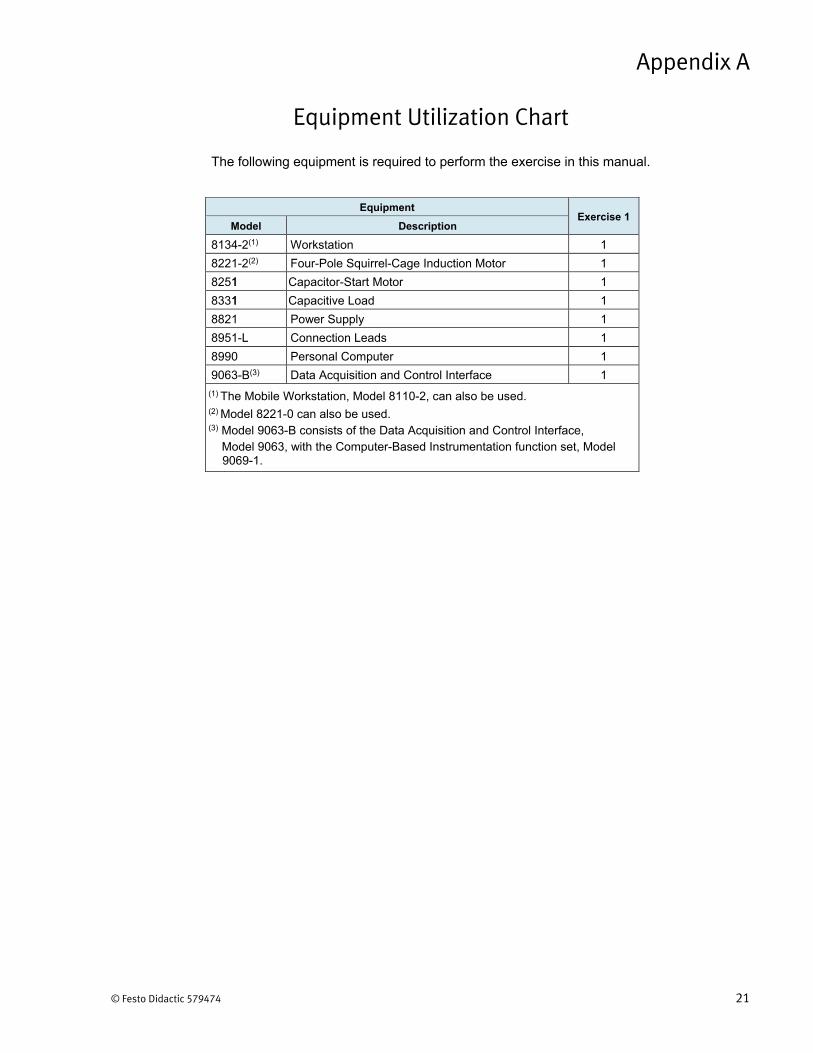
The following equipment is required to perform the exercise in this manual.
Equipment Utilization Chart
Appendix A
Equipment Exercise 1
Model Description
8134-2(1) Workstation 1
8221-2(2) Four-Pole Squirrel-Cage Induction Motor 1
82511 Capacitor-Start Motor 1
83311 Capacitive Load 1
8821 Powe Sur pply 1
8951-L Connection Le ads 1
8990 Person Comal puter 1
9063-B(3) Data Acquisition and Control Interface 1
(1) The Mobile Workstation, Model 8110-2, can also be used.(2) Model 8221-0 can also be used.(3) Model 9063-B consists of the Data Acquisition and Control Interface,
Model 9063, with the Computer-Based Instrumentation function set, Model9069-1.


© Festo Didactic 579474 23
auxiliary winding Winding used to create a phase shift between currents in the stator of the single-phase induction motor. This increases the starting torque and helps the motor start. The auxiliary winding has fewer turns of smaller-sized wire than the main winding, and thus has more resistance and less inductance than the main winding.
centrifugal switch Switch operating by centrifugal force that disconnects the auxiliary winding once the single-phase induction motor starts rotating. This is necessary because the auxiliary winding cannot support high currents for more than a few seconds without being damaged since it is made of fine wire.
eddy-current brake A fixed electromagnet that creates braking torque which acts on a squirrel-cage rotor.
electromagnetic induction
Electromagnetic induction consists in the production of an electromotive force (i.e., an induced voltage) in a circuit resulting from a change in the magnetic flux passing through that circuit. For example, a voltage is induced between the ends of a wire loop when the magnetic flux passing through the loop varies as a function of time
single-phase induction motor
Induction motor powered by a single-phase ac power source. The following two types of single-phase induction motor are commonly used: capacitor-start induction motor and split-phase induction motor.
Glossary of New Terms
Appendix B


© Festo Didactic 579474 25
Circuit Diagram Symbols
Various symbols are used in the circuit diagrams of this manual. Each symbol is a functional representation of a particular electrical device that can be implemented using the equipment. The use of these symbols greatly simplifies the number of interconnections that need to be shown on the circuit diagram, and thus, makes it easier to understand the circuit operation.
For each symbol other than those of power sources, resistors, inductors, and capacitors, this appendix gives the name of the device which the symbol represents, as well as the equipment and the connections required to properly connect the device to a circuit. Notice that the terminals of each symbol are identified using circled letters. The same circled letters identify the corresponding terminals in the Equipment and Connections diagram. Also notice that the numbers (when present) in the Equipment and Connections diagrams correspond to terminal numbering used on the actual equipment.
a When a current at inputs I1, I2, I3, or I4 exceeds 4 A (either permanently ormomentarily), use the corresponding 40 A input terminal and set the Range parameter of the corresponding input to High in the Data Acquisition and Control Settings window of LVDAC-EMS.
Appendix C
Equipment and ConnectionsSymbol
Isolated voltage and current measurement inputs
Data Acquisition and Control Interface (9063) E1
E2
E3
E4
Voltage inputs
Current inputs

Appendix C Circuit Diagram Symbols
26 © Festo Didactic 579474
Three-phase induction machine
Four-Pole Squirrel Cage Induction Motor (8221-0)
Three-phase synchronous motor
Equipment and ConnectionsSymbol
Synchronous Motor / Generator (8241-2)
Three-phase induction machine
Three-Phase Induction Machine (8221-2)

Appendix C Circuit Diagram Symbols
© Festo Didactic 579474 27
Three-phase synchronous generator
Synchronous Motor / Generator (8241-2)
Three-phase wound-rotor induction machine
Three-Phase Wound-Rotor Induction Machine (8231-B)
Equipment and ConnectionsSymbol

Appendix C Circuit Diagram Symbols
28 © Festo Didactic 579474
Power diode three-phase full-wave rectifier
Rectifier and Filtering Capacitors (8842-A)
Power thyristor three-phase bridge
Power Thyristors (8841)
Equipment and ConnectionsSymbol
Permanent Magnet Synchronous Machine (8245)
Permanent Magnet Synchronous Machine

Appendix C Circuit Diagram Symbols
© Festo Didactic 579474 29
a The electronic switch symbol in the three-phase inverter above replaces MOSFETor IGBT symbols. It is not an IEC or ANSI symbol.
Three-phase inverter
IGBT Chopper / Inverter (8837-B)
Equipment and ConnectionsSymbol


© Festo Didactic 579474 31
Index of New Terms
a The bold page number indicates the main entry. Refer to the Glossary ofNew Terms for definitions of new terms.
auxiliary winding ..................................................................................................... 8
centrifugal switch .................................................................................................... 9
eddy-current brake ................................................................................................. 6 electromagnetic induction ...................................................................................... 1
single-phase induction motor ................................................................................. 6


© Festo Didactic 579474 33
Bibliography
Boylestad, Robert L., Introductory Circuit Analysis, 11th Edition, Upper Saddle River: Prentice Hall, 2006, ISBN 978-0131730441.
Wildi, Theodore, Electrical Machines, Drives, and Power Systems, 6th Edition, Upper Saddle River: Prentice Hall, 2005, ISBN 978-0131776913.