electrical workshop first year
DESCRIPTION
Electrical Workshop First YearTRANSCRIPT
SNGCE/EE/CNF/CMELR 110
SREE NARAYANA GURUKULAM COLLEGE OF ENGINEERING
KADAYIRUPPU
DEPARTMENT OF ELECTRICAL AND ELECTRONICS ENGINEERING
LAB MANUAL FOR
ELECTRICAL WORKSHOP(CMELR 110)
FOR ALL BRANCHES
SEMESTER: ONE AND TWO

S1.No LIST OF EXPERIMENTS Page No.
1 Godown wiring 1
2 Wiring of one lamp and one plug 3
3 Wiring of mercury vapor lamp and CFL 5
4 Control of two lamps in series and parallel 7
5 Staircase wiring 9
Wiring of fluorescent lamp with magnetic andelectronic lamp
11
7 Hospital wiring 13
8 Wiring of distribution board 15
Measurement of Insulation resistance and Earthresistance
17
10 Identification of electronic components and solderingpractice
20
11 Testing of half wave and full wave rectifier withcapacitor filter
22
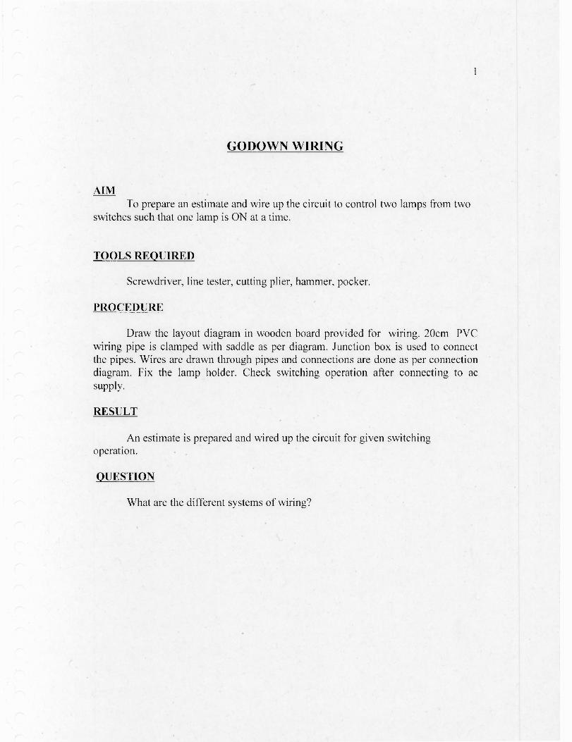
GODOWN WIRING
AIMTo prepare an estimate and wire up the circuit to control two lamps from two
switches such that one lamp is ON at a time.
TOOLS REQUIRED
Screwdriver, line tester, cutting plier, hammer, pocker.
PROCEDURE
Draw the layout diagram in wooden board provided for wiring. 20cm PVCwiring pipe is clamped with saddle as per diagram. Junction box is used to connectthe pipes. Wires are drawn through pipes and connections are done as per connectiondiagram. Fix the lamp holder. Check switching operation after connecting to acsupply.
RESULT
An estimate is prepared and wired up the circuit for given switchingoperation.
QUESTION
What are the different systems of wiring?
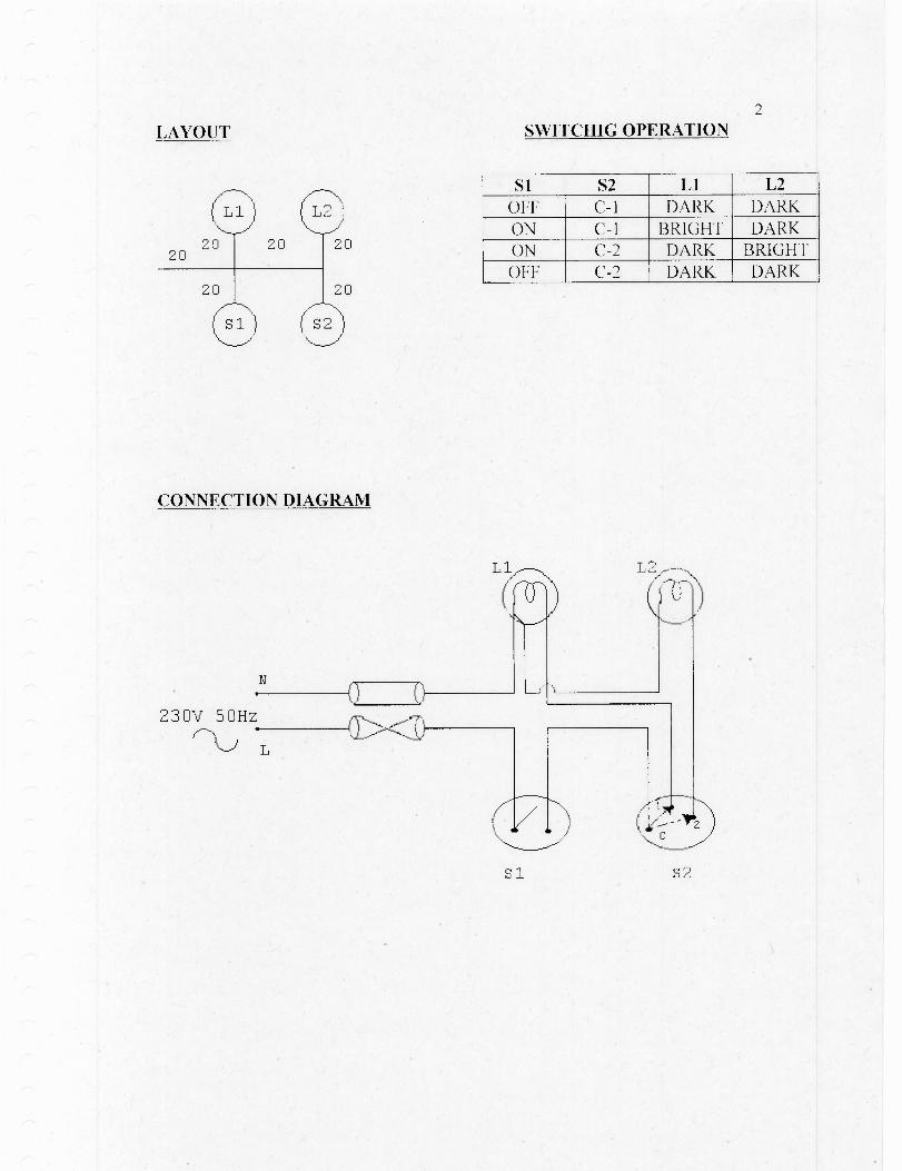
LAYOUT SWITCHIG OPERATION2
S1 S2 LI L2OFF C-1 DARK DARK
ON C-1 BRIGHT DARKON C-2 DARK BRIGHTOFF C-2 DARK DARK
20 20
2020
20
20
CONNECTION DIAGRAM
L2
Si S2
3
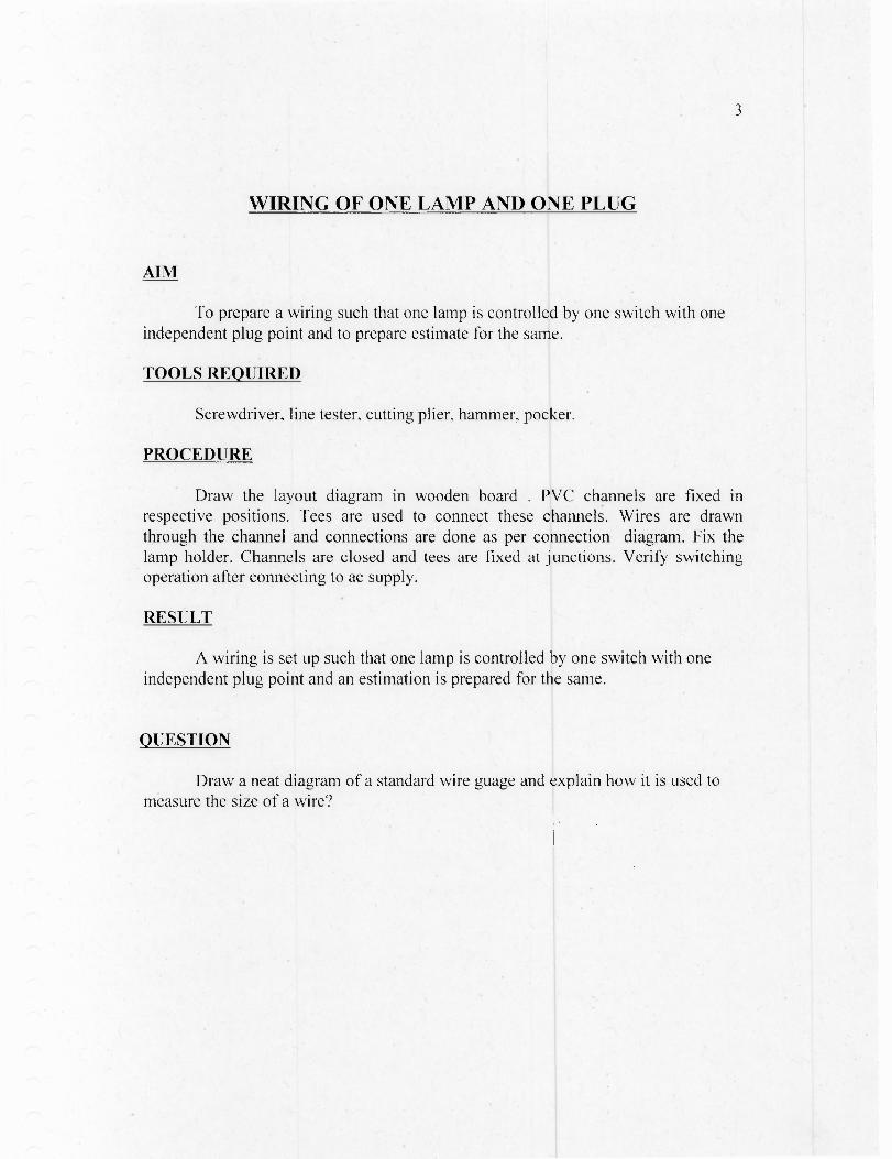
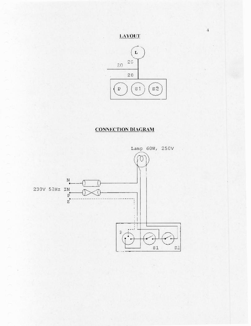
WIRING OF ONE LAMP AND ONE PLUG
AIM
To prepare a wiring such that one lamp is controlled by one switch with oneindependent plug point and to prepare estimate for the same.
TOOLS REQUIRED
Screwdriver, line tester, cutting plier, hammer, pocker.
PROCEDURE
Draw the layout diagram in wooden board . PVC channels are fixed inrespective positions. Tees are used to connect these channels. Wires are drawnthrough the channel and connections are done as per connection diagram. Fix thelamp holder. Channels are closed and tees are fixed at junctions. Verify switchingoperation after connecting to ac supply.
RESULT
A wiring is set up such that one lamp is controlled by one switch with oneindependent plug point and an estimation is prepared for the same.
QUESTION
Draw a neat diagram of a standard wire guage and explain how it is used tomeasure the size of a wire?
2 CI
20
PD S i
Lamp 60W, 250V
N
230V 50Hz IN
2.---1C/><T•
E
S1
LAYOUT
LI)20
CONNECTION DIAGRAM
NI
A
R
- Main Electrode
5
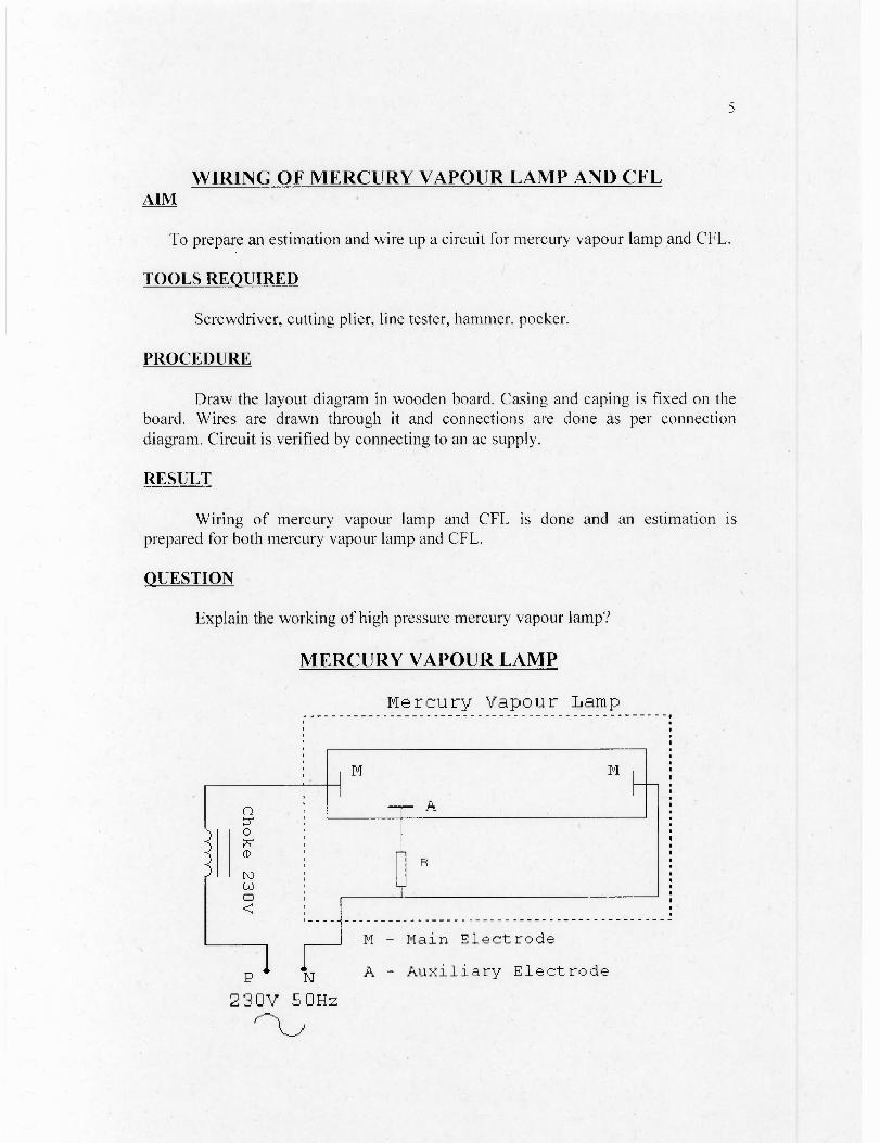
WIRING OF MERCURY VAPOUR LAMP AND CFLAIM
To prepare an estimation and wire up a circuit for mercury vapour lamp and CFL.
TOOLS REQUIRED
Screwdriver, cutting plier, line tester, hammer, pocker.
PROCEDURE
Draw the layout diagram in wooden board. Casing and caping is fixed on theboard. Wires are drawn through it and connections are done as per connectiondiagram. Circuit is verified by connecting to an ac supply.
RESULT
Wiring of mercury vapour lamp and CFL is done and an estimation isprepared for both mercury vapour lamp and CFL.
QUESTION
Explain the working of high pressure mercury vapour lamp?
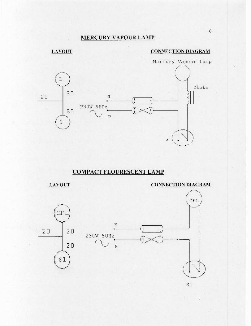
MERCURY VAPOUR LAMP
Mercury Vapour Lamp
A - Auxiliary Electrode
230V 50Hz
2 0 20
230V 50Hz 20
( 9
Choke
p
Ca)
6MERCURY VAPOUR LAMP
LAYOUT CONNECTION DIAGRAM
Mercury Vapour Lamp
COMPACT FLOURESCENT LAMP
LAYOUT CONNECTION DIAGRAM
20 20N
230V 50Hz
20
C...S )
S1
CONTROL OF TWO LAMPS IN SERIES AND PARALLEL
AIM
To connect two lamps in series and parallel and to prepare the estimate for thesame.
TOOLS REQUIRED
Screwdriver, line tester, cutting plier, hammer, pocker.
PROCEDURE
Draw layout diagram in wooden board provided. 20cm PVC wiring pipe isclamped with saddle as per diagram. Junction box is used to connect these pipes.Wires are drawn through the pipes and connections are done as per connectiondiagram. Fix the lamp holder. Close the junction box. Verify the switching operationafter connecting to ac supply.
RESULT
A wiring is setup to control two lamps in series and parallel and an estimationis prepared for the same.
QUESTION
Why ACSR conductor is used for overhead lines?
7
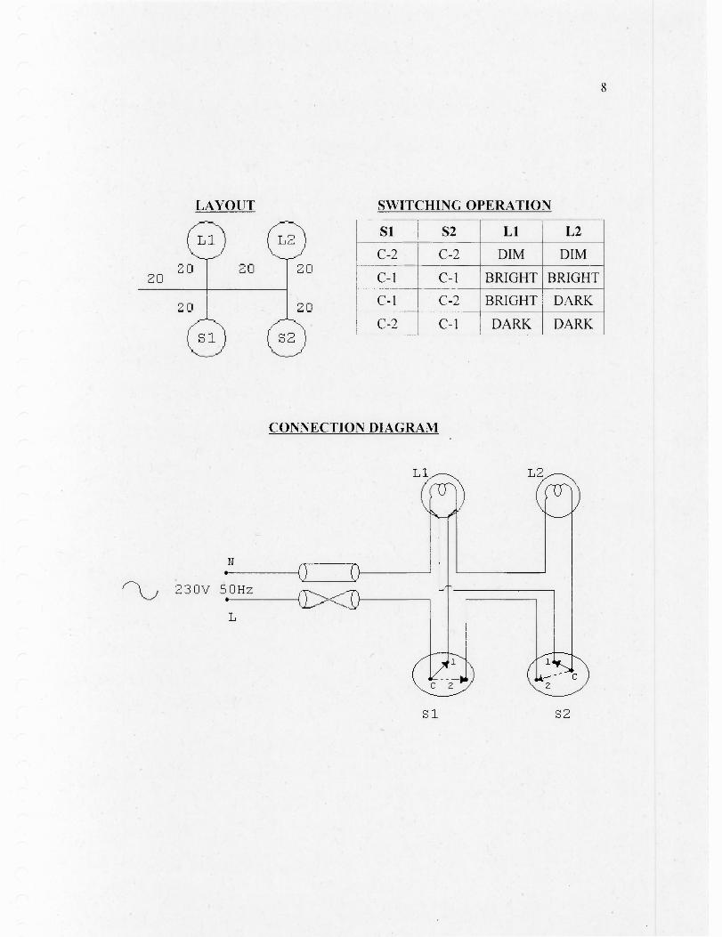
8
LAYOUT
SWITCHING OPERATION
411020 20 20
20
20 20
Si S2 Ll L2
C-2 C-2 DIM DIM
C-1 C-1 BRIGHT BRIGHT
C-1 C-2 BRIGHT DARK
C-2 C-1 DARK DARK
CONNECTION DIAGRAM
S1
S2

STAIRCASE WIRING
AIM
To connect two switches in order to control one lamp so that it can becontrolled by each one independently. Also prepare the estimate for the same.
TOOLS REQUIRED
Screwdriver, line tester, cutting plier, hammer, pocker.
PROCEDURE
Draw layout diagram in wooden board provided. According to layout casingand caping is fixed on the board. Wires are drawn through it and connections are doneas per connection diagram. Fix the lamp holder. Verify the switching operation afterconnecting to ac supply.
RESULT
A wiring is setup to connect two switches in order to control one lamp so thatit can be controlled by each one independently. Also prepared the estimation for thesame.
QUESTION
What are different types of conductor materials?
9
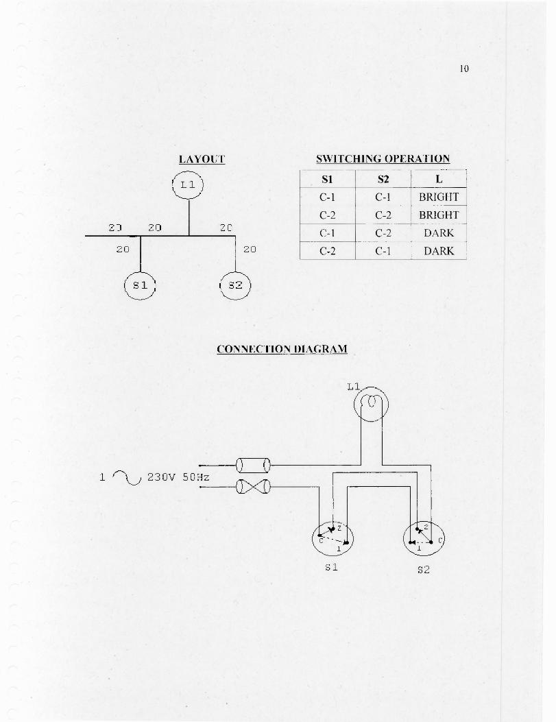
10
LAYOUT
SWITCHING OPERATION
Si S2 L
C-1 C-1 BRIGHT
C-2 C-2 BRIGHT
C-1 C-2 DARK
C-2 C-1 DARK
CONNECTION DIAGRAM
L
1 2 3 0 V 5 0Hz
Si S2

WIRING OF FLUORESCENT LAMP WITH MAGNETIC ANDELECTRONIC CHOKE
AIM
Set up a wiring of fluorescent lamp with electronic and magnetic choke and toprepare an estimation for the same.
TOOLS REQUIRED
Screwdriver, Line tester, cutting plier.
PROCEDURE
Connections are done as per circuit diagram 1. Supply is given and circuitdiagram is tested. Then second diagram is set up and checked by connecting to acsupply.
RESULT
Wiring of fluorescent lamp with electronic and magnetic choke is done and anestimation is prepared for the same.
QUESTION
Explain the working of fluorescent lamp?
11

FLUORESCENT LAMP WITH MAGNETIC CHOKE
G1 cnvul type start e
23 OV SOHz
FLUORESCENT LAMP WITH ELECTONIC CHOKE
12
230V 50Hz
HOSPITAL WIRING
AIM
To prepare an estimate and wire up the circuit to control two lamps with twoswitches (one way switch and two way switch) so as to get both dim, both bright andonly one bright.
TOOLS REQUIRED
Screwdriver, cutting plier, line tester, hammer, pocker.
PROCEDURE
Draw layout diagram in wooden board provided. 20cm PVC wiring pipe isclamped with saddle as per diagram. Junction box is used to connect these pipes.Wires are drawn through the pipes and connections are done as per connectiondiagram. Fix the lamp holders. Close the junction box. Verify the switching operationafter connecting to ac supply.
RESULT
A circuit is wired up to control two lamps with two switches so as to get bothdim,both bright and only one bright and an estimation is prepared for the same.
QUESTION
Compare AC and DC systems of supply.
13
14
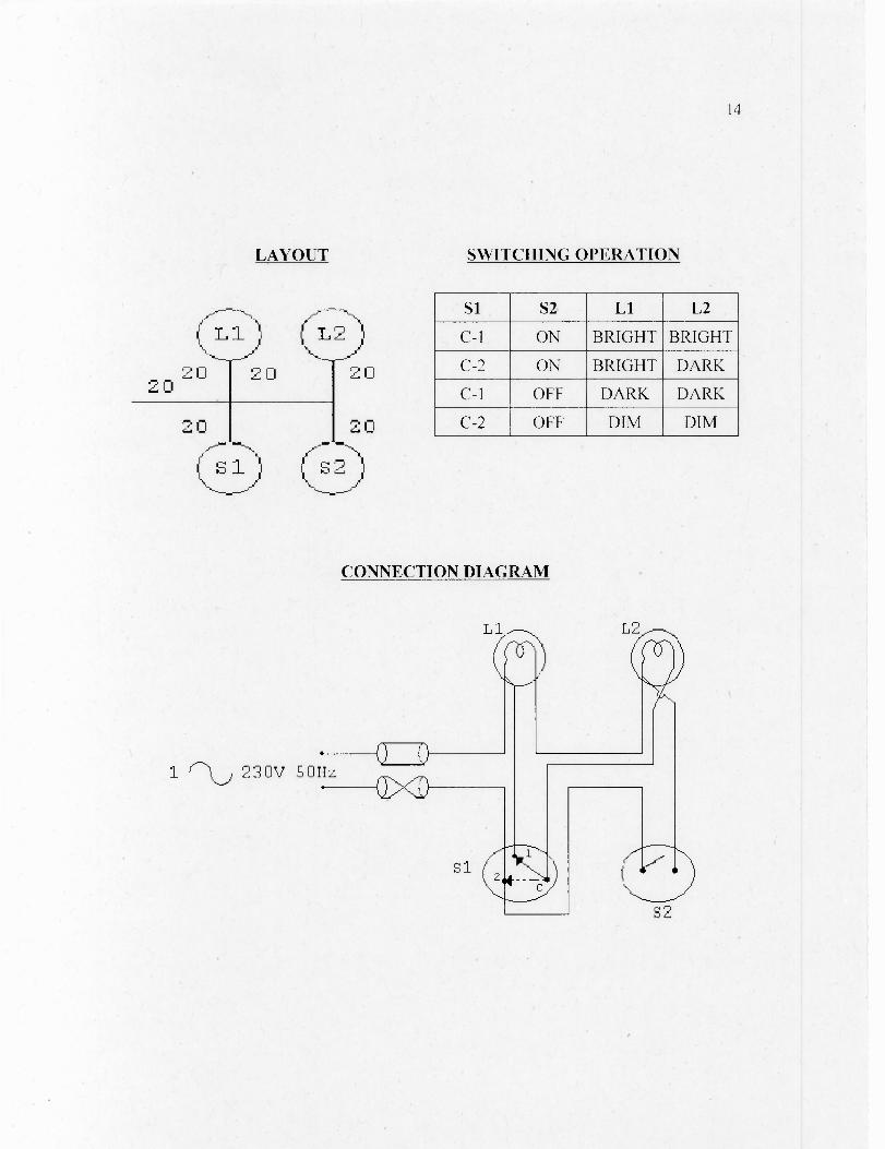
Si S2 Ll L2
C-1 ON BRIGHT BRIGHT
C-2 ON BRIGHT DARK
C-1 OFF DARK DARK
C-2 OFF DIM DIM
0 2 02
L i L-2)
2D 20
2 0 20C:D
14
LAYOUT SWITCHING OPERATION
CONNECTION DIAGRAM
L
1 f b 230v 50 Hz
S2
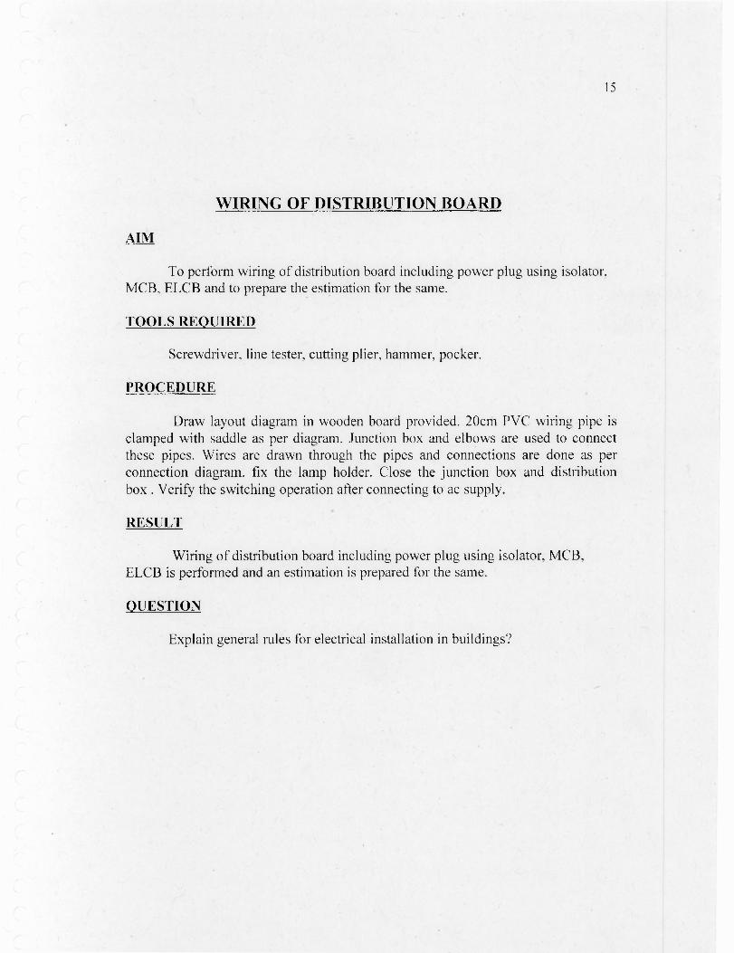
WIRING OF DISTRIBUTION BOARD
AIM
To perform wiring of distribution board including power plug using isolator,MCB, ELCB and to prepare the estimation for the same.
TOOLS REQUIRED
Screwdriver, line tester, cutting plier, hammer, pocker.
PROCEDURE
Draw layout diagram in wooden board provided. 20cm PVC wiring pipe isclamped with saddle as per diagram. Junction box and elbows are used to connectthese pipes. Wires are drawn through the pipes and connections are done as perconnection diagram. fix the lamp holder. Close the junction box and distributionbox . Verify the switching operation after connecting to ac supply.
RESULT
Wiring of distribution board including power plug using isolator, MCB,ELCB is performed and an estimation is prepared for the same.
QUESTION
Explain general rules for electrical installation in buildings?
15
PN
17
MEASUREMENT OF INSULATION RESISTANCE AND EARTH RESISTANCE
INSULATION MEGGARAIM
To measure the resistance of insulation using insulation meggar.
APPARATUS
Insulation meggar.
PROCEDURE
Terminals of the meggar are connected across the primary winding (A A') of atransformer whose resistance is to be measured. Similarly the secondary winding (BB') resistance is measured. Then the terminals are connected to the winding (B) andthe body of the transformer (C) and resistance is measured. Insulation resistancebetween primary and secondary winding is also measured.
RESULT
Resistance between terminals of primary winding =Resistance between terminals secondary winding =Insulation resistance between the winding and body of the transformer =Insulation resistance between the primary and secondary winding of transformer =
19.
EARTH MEGGARAIM
To measure the resistance of earth using earth meggar.
APPARATUS
Earth meggar, three aluminium rods, connecting wires, hammer.
PROCEDURE
Terminals C1 and P1 are shorted and is connected to earth electrode.10m ismeasured from the earth electrode and a rod is driven there. It is connected to C2.Another rod 2.5m from earth electrode is driven and connected to P2. Reading istaken. Then second rod is shifted to 5m from earth electrode and connected to P2.Reading is taken. The procedure is repeated for 7.5m from earth electrode. Averageof these three readings gives the earth resistance.
RESULT
Earth resistance =
QUESTION
Why switches and fuses are provided in phase line?
18
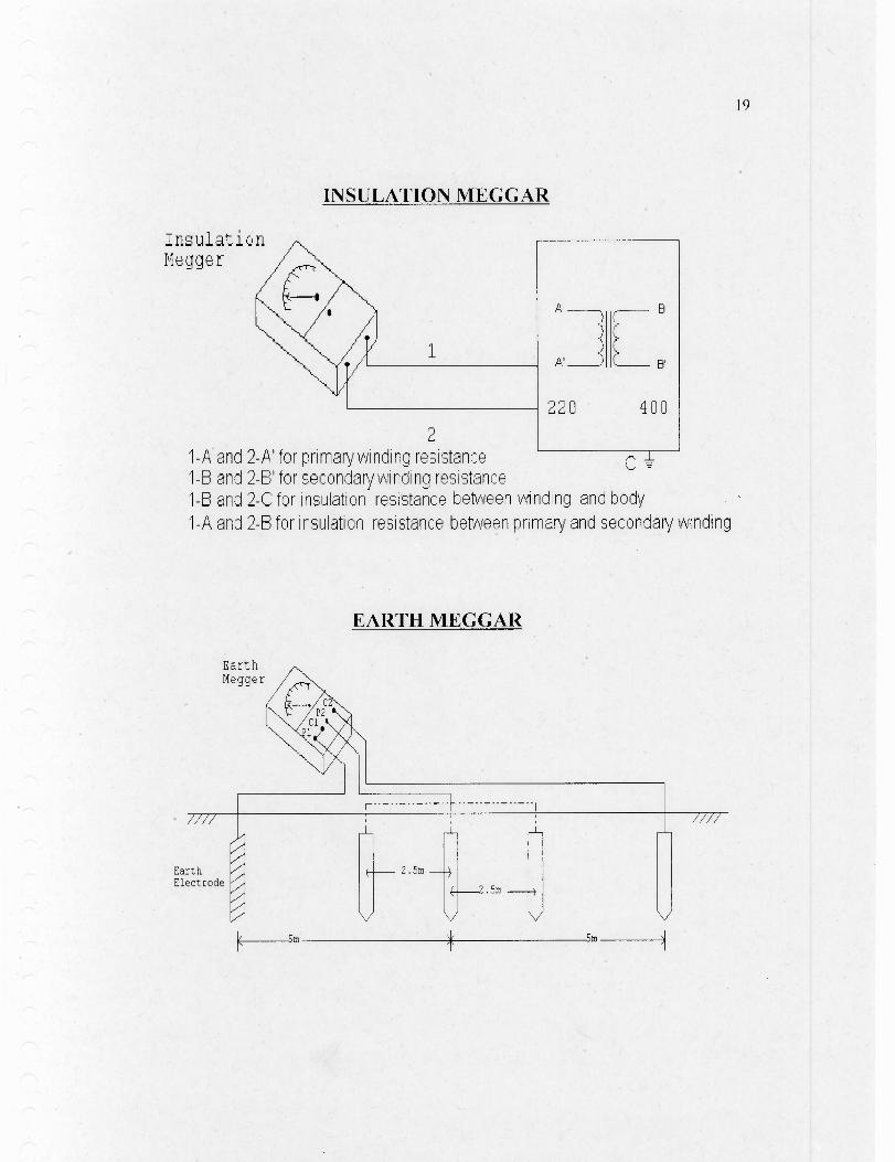
EarthMegger
EarthElectrode
INSULATION MEGGAR
InsulationMegger
21-A and 2-A' for primary winding resistance C1-B and 2-B' for secondary winding resistance1-B and 2-C for insulation resistance between winding and body1-A and 2-B for insulation resistance between primary and secondary winding
EARTH MEGGAR
19

20
IDENTIFICATION OF ELECTRONIC COMPONENTS ANDSOLDERING PRACTICE
AIM
Identification of electronic components.To practice soldering and to prepare the estimation for the same.To solder an IC base and wires in a PCB.Insert a logic gate in the IC base and verify its function using IC tester.
TOOLS REQUIRED
Soldering iron, lead, desoldering pump, leg strip, printed circuit board, wire,IC, cutting plier.
PROCEDURE
The given electronic components are identified. For soldering of copper wirethe steps are given belowFirst clean the leg strip. The insulation from the end of copper wire is removed andclean it. Then apply soldering paste to end of wire. When soldering iron is heatedplace the copper wire into the hole of the leg strip. Solder it to leg strip usingsoldering lead.To solder the pins of IC base to the PCB the same procedure is used. Insert an IC tothe IC base and truth table is verified using IC tester.Then desoldering is done using desoldering pump. For desoldering first heat thesoldering iron and melt the soldering paste with the desoldering pump. Removeconnection and clean leg strip.
RESULT
The given electronic components are identified and the soldering has beenpracticed and prepared the estimation for the same. Soldered an IC base and wires ina PCB. Inserted logic gate in the IC base and it's function is verified using IC tester.
QUESTIONS
Explain the working of soldering iron?What are the different factors to be considered to get good soldering joint?
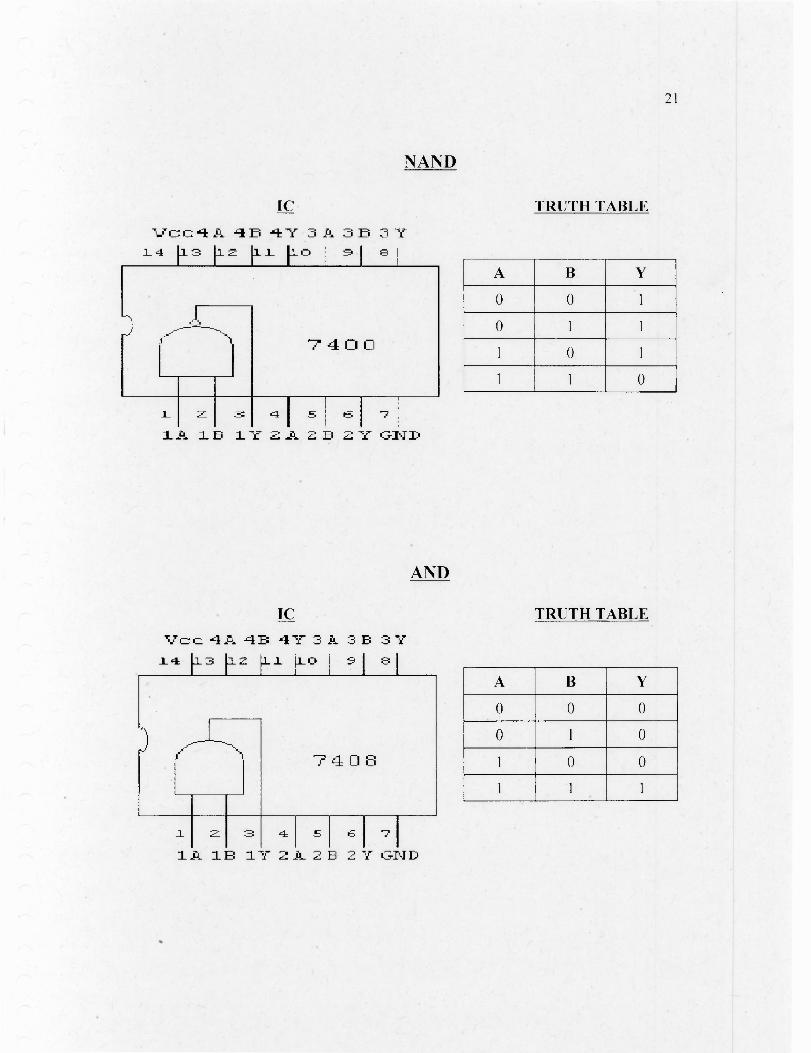
nIcc. 4A 4B 41.- 3 A. 3 B_L4 113 r.2 [Li 1.1.0 9 I 8 1
7 4 0 8
5 1A 1E 1V 2A 2 B 2 Ir GIN
NAND
IC
TRUTH TABLE
21
1.1Gc40.. "=ID -•+ -"T 3A 3D 3y14 113 EL2 111 Fa 3 e I
7 4 CI
L 3' 4 I .51A 1_D 1Y ZA ED EY QT•ID
A B Y
0 0 1
0 1 1
1 0 1
1 1 0
AND
IC
TRUTH TABLE
A B Y
0 0 0
0 1 0
1 0 0
1 1 1
22
TESTING OF HALF WAVE AND FULL WAVE RECTIFIERWITH CAPACITOR FILTER
AIM
To prepare an estimate and to setup a half wave and full wave rectifierwith and without capacitor filter.
TOOLS REQUIRED
Diode, resistor,capacitor,transformer,bread board, wires.
PROCEDURE
The primary of transformer is connected to an ac supply. Thesecondary is connected to bread board. The insertion of wires into bread boardis done. Resistor, capacitor and diodes are also inserted into bread board as percircuit diagram. The output is taken across resistor and is connected to cathoderay oscilloscope. The output waveform is displayed on the CRO. Thewaveforms are obtained with and without capacitor filter.
RESULT
Testing of half wave and full wave rectifier with and without capacitorfilter is done.
QUESTION
Explain the working of half wave and full wave rectifier with andwithout filter.
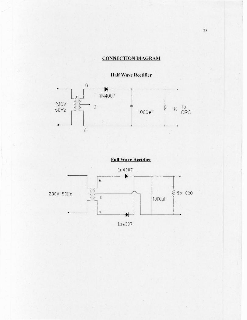
230V 50Hz
•
CONNECTION DIAGRAM
Half Wave Rectifier
6
6
Full Wave Rectifier
1N4007
--+H-
--)
-:-5
C-
L
1
c_____________(-\_0
T
1000pF
To CRO
6-41—
1N4007
23