electrical resitivity of glass in furnaces with coaxially mounted cylindrical electrodes
TRANSCRIPT
ELECTRICAL RESITIVITY OF GLASS IN FURNACES WITH COAXIALLY
MOUNTED CYLINDRICAL ELECTRODES
K. M. Tatevosyan and Yu. N. Petrosyan UDC 666.1.031.5
Electric glass-melting furnaces (EGF) are widely used in industry. This made it neces- sary to develop new designs to ensure the highest efficiency and to enable hard glass compo- sitions to be melted. One such design is the EGF with coaxially mounted cylindrical elec- trodes, the central one of which is simultaneously an output unit [la].
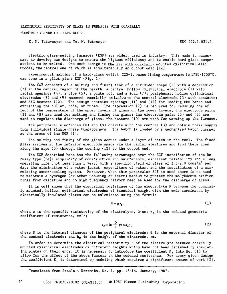
Experimental melting of a hard-glass cullet C25-I, whose fining temperature is 1720-1750~ was done in a pilot plant EGF (Fig. I).
The EGF consists of a melting and fining tank of a six-sided shape (i) with a depression (2) in the central region of the hearth; a central hollow cylindrical electrode (3) with radial openings (4), a pipe (5), a plate (6), and a lead (7); peripheral, hollow cylindrical electrodes (8) and (9) mounted coaxially relative to the central electrode (3) with conduits; and SiC heaters (I0). The design contains openings (II) and (12) for loading the batch and extracting the cullet, rods, or tubes. The depression (2) is required for reducing the ef- fect of the temperature of the upper layers of glass on the lower layers; the electrode pairs (3) and (8) are used for melting and fining the glass; the electrode pairs (3) and (9) are used to regulate the discharge of glass; the heaters (i0) are used for warming up the furnace.
The peripheral electrodes (8) and (9) operate with the central (3) and obtain their supply from individual single-phase transformers. The batch is loaded by a mechanized batch charger at the crown of the EGF [i].
The melting and fining of the glass occurs under a layer of batch in the tank. The fined glass arrives at the interior electrode space via the radial apertures and from there goes along the pipe (5) through the opening (12) to the output end.
The EGF described here has the following advantages over the EGF installation of the De Bussy type [2a]: simplicity of construction and maintenance; excellent reliability and a long operating life (not less than 1 year) with a specific yield of glass of 2.5-2.8 tons/m 2 per day; the elimination of a waterjacket, expenditure of water, and the installation of a cir- culating water-cooling system. Moreover, when this particular EGF is used there is no need to maintain a hydrogen (or other reducing or inert) medium to protect the molybdenum orifice rings from oxidation and no high-frequency network need be used for the discharge of glass.
It is well known that the electrical resistance of the electrolyte R between the coaxial- ly mounted, hollow, cylindrical electrodes of identical height with the ends terminated by electrically insulated plates can be calculated using the formula
~=p%, (i)
where O is the specific resistivity of the electrolyte, ~'cm; r e is the reduced geometric coefficient of resistance, cm-1;
D re=In -~ (2~he), (2)
where D is the internal diameter of the peripheral electrode; d is the external diameter of the central electrode; and h e is the height of the electrode, cm.
In order to determine the electrical resistivity R of the electrolyte between coaxially mounted cylindrical electrodes of different heights which have not been finished by insulat- ing plates on their ends, it is necessary to introduce the coefficient K x into Eq. (i) to allow for the effect of the above factors on the reduced resistance. For every given design the coefficient K I is determined by modeling which requires a significant amount of work [2].
Translated from Steklo i Keramika, No. I, pp. 15-16, January, 1987.
14 0361-7610/87/0102-0014512.50 O 1987 Plenum Publishing Corporation
[0 Y i
/
" I ' /
�9 r / /
3 6 !2 Z
Fig. 1
a) Level of melt b)
~i ~ 27 =
1
!
+
J
Fig. 2
c)
f
+
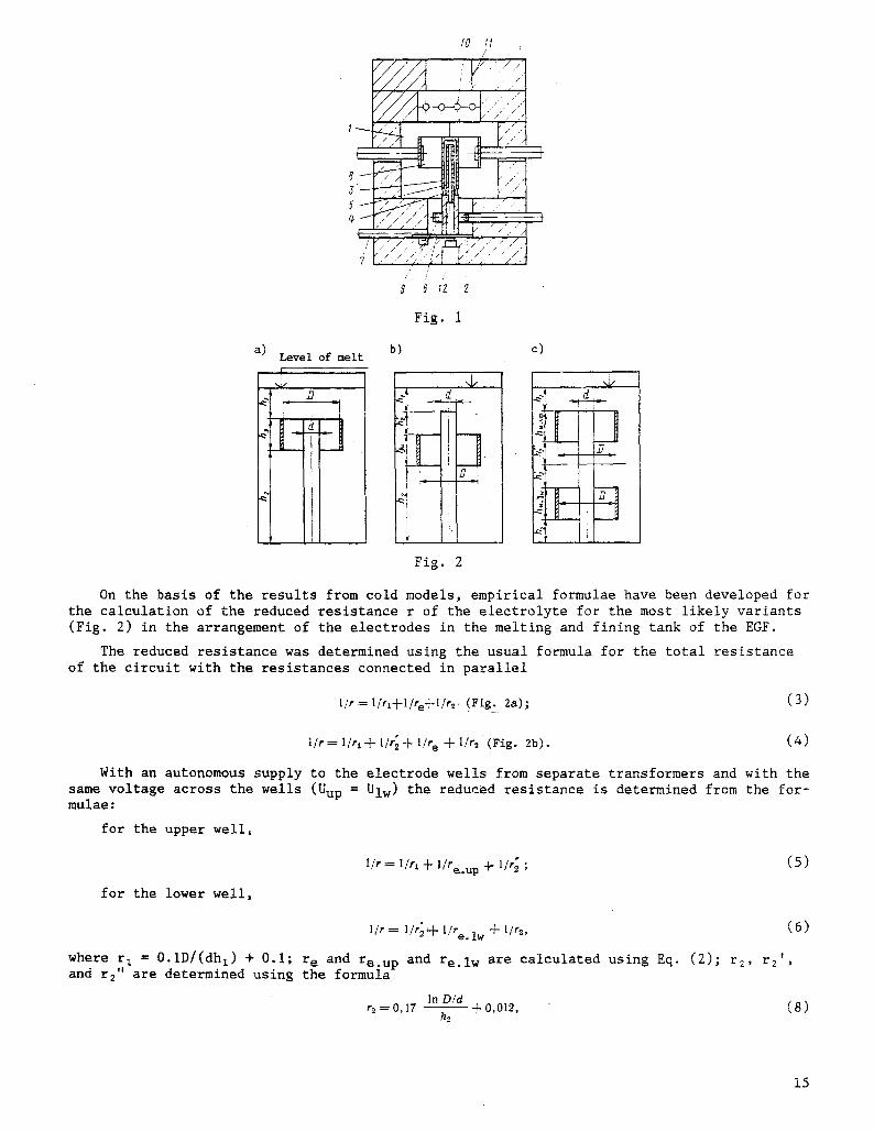
On the basis of the results from cold models, empirical formulae have been developed for the calculation of the reduced resistance r of the electrolyte for the most likely variants (Fig. 2) in the arrangement of the electrodes in the melting and fining tank of the EGF.
The reduced resistance was determined using the usual formula for the total resistance of the circuit with the resistances connected in parallel
l / r = l/rl-F1/re-Fl/r 2. (Fig. 2a); (3)
l / r -~ l / r , J t-1/r'2- F l /r e Jr-1/r~ ( F i g . 2 b ) . (4)
With an autonomous supply to the electrode wells from separate transformers and with the same voltage across the wells (Uup = Ulw) the reduced resistance is determined from the for- mulae:
for the upper well,
for the lower well,
1/r = I/rl 4- l /re. .u p 4" 1/r~ ; (5)
!/r = !//2'4- 1/re. lw 4- !/r~,
where r I = O.iD/(dhl) + 0.i; r e and re.up and re.lw are calculated using Eq. (2); and r2" are determined using the formula
In D/d r2 = 0, 17 - - -{- 0,012,
hz
(6)
r 2 , r2 t ,
(8)
15
after substituting h 2' and h2" for the corresponding r 2' and r2"
We must take into account that in the case of variant c (Fig. 2), when Uup = Ulw ' h 2 ' = h2" [ 3 ] .
Equations (3) - (8) were derived for values of D/(dhz) , D/(dh2), D/(dh2') and D/(dh2") equal to 0.05-8.
For variant c (Fig. 2) when Uup > Ulw, the reduced resistances for each well are cal- culated using the following formulae:
for the upper well,
for the lower well,
1/r = 1/r 1 4:- 1/re.up+ l / ( n u p r'2) ; (g)
I/r = I/(nlw r'2) 4:- life. lw 4:- |/r~, (10)
where nu p = ~Ulw/Uup ; (ii)
and nl w = v/Uup/Ulw . (12)
Equations (9) - (12) are derived with 0.2 ~D/(dh 2) <~- 2 and Uup = (l.05-1.25)Ulw.
From the empirical formulae we can calculate the reduced resistance to an accuracy of 0 _+ 5%.
The resistance of the glass in furnaces with coaxially arranged cylindrical electrodes is determined using the expression:
R = K 2 p r ,
where K 2 is a coefficient taking into account the effect of the temperature nonuniformity of the glass in relation to the height of the tank; r is the reduced resistance determined for each case using Eqs. (3)-(6), (9) and (i0)o
The coefficient K 2 depends on the composition of the glass. For alkali and low-alkali glass, K 2 = 1.05-1.1 and for alkali-free glass, K 2 = i. Iai.25.
The design of the EGF described here can be recommended for use in the production of culler, glass rods, and tubes from glasses with a fining temperature up to 1750~
LITERATURE CITED
i~ K. Mo Tatevosyan, A. V. Karaustayan, P. B. Korukhchyan et al., "An electric glass-melting furnace for the production of glass cullet," Steklo Keramo, No. 8, 9-11 (1982).
2. USSR Patents, Nos. 501979 and 802207. 3. A. F. Melik-Akhnazarov and K. M. Tatevosyan, "Determination by modeling of the resistance
between electrodes of an electric glass-melting furnace," Izv. Akad. Nauk Armenian SSR, Ser. Tekh. Nauk, 12, No. 5, 47-54 (1959).
4. French Patent No. 1482084. 5. K. M. Tatevosyan, "Electrical resistance of glass in furnaces with a single-phase supply,"
Steklo Keram., No. 2, 8-10 (1984).
16