electrical preventive maintenance pays - … preventive maintenance pays off! a case study on...
TRANSCRIPT

Electrical Preventive Maintenance Pays Off! A case study on controlling risks to plant & profits
Joe Gierlach ~ Director, Technical Training and Support TEGG Corporation ~ Pittsburgh, PA
ABSTRACT:
Electrical power has become the life blood of our everyday needs. In a manufacturing environment where today’s “lean manufacturing” and “just in time” delivery philosophies are making reliability and plant uptime more critical than ever before, dependable electrical distribution is not an option – it is critical to corporate fiscal health. What would be the impact on your company if a major component in your facility’s electrical distribution system experienced a catastrophic failure? What would happen to your plant’s production line, data center or distribution center? Would the lost opportunity revenue, added to the repair or replacement costs for critical equipment, be more or less than the dollars saved by not having a proactive Electrical Preventive Maintenance (EPM) program in place? What if the cost of damaged customer loyalty and satisfaction are taken into consideration? Let’s take a look at a recent real‐life example where a costly disaster was averted because of an effective EPM program.
INTRODUCTION: Global competition has forced production quotas in many companies and industries to increase. At the same time, many of these companies have experienced a reduction in their labor force and maintenance budgets as organizations attempt to improve their bottom lines, increase productivity, improve cash flow, and lower operating costs. Now consider that the typical useful service life of electrical equipment is generally 25‐30 years depending on maintenance and upkeep, and much of our aging infrastructure equipment has been in service for 20 years or more while receiving less than the recommended annual service regimen. Ultimately, companies are finding that catastrophic failure is the unintended consequence of exposing their electrical distribution equipment to extended stresses, more extreme environmental operating conditions, and additional load demands from facility upgrades. Depending on the criticality of the equipment, an arc flash or other destructive electrical failure can literally devastate a planned maintenance budget while the associated downtime and resulting interruptions to processes can affect revenue, profits, and ultimately stock prices in some cases.

Production and Reliability Managers face a very real challenge as they try to balance the demands and goals of management, customers, and equipment reliability. Resources such as NFPA 70B can give these managers a clear direction in their effort to enlist the support of others to reduce the risk of catastrophic failures through an EPM program, thereby safeguarding and enhancing profitability. The NFPA (National Fire Protection Association) has developed some of the world’s most referenced and respected codes for fire and electrical safety by enlisting a broad consensus of experts. NFPA 70B (4.1) clearly outlines the benefits and details of an effective EPM program stating that “dependability can be engineered and built into equipment, but effective maintenance is required to keep it dependable. Experience shows that equipment lasts longer and performs better when covered by an EPM (Electrical Preventative Maintenance) program.” The NFPA 70B goes on to state that “Infrared inspections of electrical systems are beneficial to reduce the number of costly and catastrophic equipment failures and unscheduled plant shutdowns.” The standard recommends that “routine infrared inspections of energized electrical systems should be performed annually prior to shutdown. More frequent infrared inspections, for example, quarterly or semiannually, should be performed where warranted by loss experience, installation of new electrical equipment, or changes in environmental, operational, or load conditions.… Infrared surveys should be performed during periods of maximum possible loading but not less than 40 percent of rated load of the electrical equipment being inspected.” A key to enabling managers to accomplish the goals of NFPA 70B and safeguarding plant assets by reducing or eliminating risks to plant and personnel, is to design an EPM program which is minimally disruptive to operations so that they are also able to meet the demands of increased production and profitability. This is where the expertise of the professionals at TEGG Services pays dividends – providing tangible value with services tailored for specific objectives and implemented without interruption to operations.
Case Study Feyen‐Zylstra, LLC, a large electrical contractor located in Grand Rapids, Michigan, secured an Electrical Preventive Maintenance (EPM) program with a new customer located in Middleville, Michigan. The maintenance agreement included a value‐added product and service that was comprised of the installation of 40 IRISS infrared windows (or “IR viewing panes”) on the critical 8.3 KV equipment throughout the facility.

Bradford White Corporation, an employee‐owned organization, has been manufacturing products ranging from tubs to water heaters since 1881. Production runs 24 hours per day, 6 days per week with approximately 1600 employees. Craig Potter, Facility Electrical Engineer, has been with the organization for the past 18 years and in his current position for the past 12 years. There are traditionally two weeks per year (in July and November) that are earmarked for maintenance shutdown in the facility. Reliability and minimal downtime topped the list of the facility’s planning priorities. The two scheduled maintenance weeks cause production to cease, which in turn impacts the organization’s profitability. With these concerns in mind, Mr. Potter quickly recognized the benefit of protecting the facility’s profitability by minimizing the risk of electric failures which could cause unscheduled outages. However, it was also important that any such solutions could not interfere with their production and processes.
Feyen‐Zylstra and TEGG were able to demonstrate to Mr. Potter how an EPM program could be implemented to ensure the health of his power distribution while being totally transparent to his production schedule and processes while eliminating added arc flash risks during surveys. Mr. Potter worked with the maintenance sales professionals at Feyen‐Zylstra to identify the operation’s most critical equipment and processes. The result was a detailed, custom road‐map to help ensure uptime and profitability by reducing risk to the facility’s core processes through the implementation of an EPM. Execution of the service plan started within weeks. The first phase of implementing the program was to install the 40 IRISS VPFR infrared windows (as seen in Figure #1) during the
scheduled maintenance shutdown on July first at Bradford White. A crew of 11 technicians completed the installations and performed cleaning and housekeeping tasks on the high‐voltage equipment at that time. Once this task was completed over the holiday weekend, Feyen‐Zylstra’s certified technicians, Mark DenHartigh and Bruce Boer (Figure #2), began to conduct the energized maintenance services. Mark DenHartigh & Bruce Boer
Figure #2
IRISS VPFR IR Window Figure #1

DenHartigh has been applying the TEGG Services for Feyen‐Zylstra since the completion of his initial technical training in Pittsburgh, PA, in July 2005, and Boer completed his initial training in June 2006. The technicians received training on TEGGTask® maintenance tasking software, ultrasonic testing, TEGG/ASNT Level I infrared certification, power quality, and NFPA‐70E electrical safe work practice training. An Anomaly is Discovered: During the second week of the service, the technicians identified a thermal exception on one of the 8.3 KV Cutler Hammer Load Interrupter Switches. These switches are a critical part of the facility’s power distribution system, feeding a 2000 KVA transformer which reduces the voltage to 480 volts for distribution to much of the production equipment. Due to the criticality of this switch and the process it is involved with, it was one of the pieces of equipment which had received the installation of an infrared window. Because the IR windows gave the thermographers access to thermographic data of energized components while the panel covers remained closed, the surveys could be performed safely and efficiently without disruption to processes and without the added risk of arc flash associated with open‐panel inspections. DenHartigh identified the line side of the “B” Phase 14.4 KV, 200‐amp fuse as the area of interest. At this time (second week of service), the spot temperature of the fuse displayed 64°C (147°F) on the infrared camera. The source of the temperature was oxidized aluminum, and it is important to note that the initial temperature calculation was uncompensated and did not correct for the low Emissivity of the target. Emissivity represents the efficiency at which an object emits infrared radiation; infrared radiation is what an infrared imager or “camera” detects and uses to calculate temperatures. The less efficiently an object emits radiation, the lower the temperature would appear to the camera (if the object is at a higher temperature than the reflected background radiation). Although an object may be experiencing a significant temperature, the camera’s interpretation of the temperature of this low Emissivity target would be dramatically lower since the amount of emitted radiation is significantly less than if the target was made of a higher Emissivity material (ie. a more efficient emitter of infrared radiation). Refer to Stefan‐Boltzmann law of W = ∈σT4. The area of concern on the top of the fuse is clearly visible in Figure #3. This image was taken through a VPFR
Figure #3

infrared window with the camera’s parameters properly configured to compensate for the external optics (including Transmissive properties of the window and window temperature). The problem temperature (“Prob” on the screen shot) is indicating 64°C (147°F) with the Emissivity set at .96 which is characterized as “uncompensated.” The anomaly was identified and documented as an area of concern to be monitored for signs of deterioration. The training and certification program, along with the intimate knowledge that electricians possess about the equipment they maintain, is critical to making sound judgment calls on issues such as this. To the untrained eye, the temperature is within acceptable operating parameters. With the TEGG/ASNT Certification program, the execution of this technology is designed to eliminate any uncertainties on such issues. Knowing that this clamp is manufactured with a material that is NOT efficient at emitting radiation (only about a .5 efficiency), the technicians were aware that a camera adjustment was necessary in order to obtain more accurate temperature information. Once this adjustment was made, the 64°C (147°F) temperature was corrected to reflect a more accurate temperature to 107° C (224.6°F), illustrating an error of over 40°C (104°F). These findings prompted the service provider to more closely monitor the fuse clamp; monitoring intervals for this switch were changed to weekly surveys. The technicians continued their service routine over the next ten days at which time TEGG Corporation was scheduled to pay a training and support visit to Bradford White. Upon the arrival of the TEGG Technical Support, DenHartigh advised the instructor of the issue (as he was seeking a second opinion) and asked the instructor to accompany him to view the fuse clamp as part of the agreed upon monitoring cycle. As Figure #4 demonstrates, the result of this survey proved to be far more alarming than the initial survey: The problem temperature had increased to 252°C (486°F) in just ten days since first identified. The new temperature represented an increase over 300%, indicating a significant and accelerated deterioration of the assembly. Figure #4
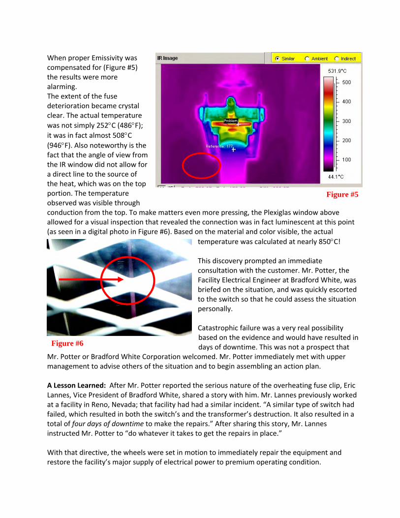
When proper Emissivity was compensated for (Figure #5) the results were more alarming. The extent of the fuse deterioration became crystal clear. The actual temperature was not simply 252°C (486°F); it was in fact almost 508°C (946°F). Also noteworthy is the fact that the angle of view from the IR window did not allow for a direct line to the source of the heat, which was on the top portion. The temperature observed was visible through conduction from the top. To make matters even more pressing, the Plexiglas window above allowed for a visual inspection that revealed the connection was in fact luminescent at this point (as seen in a digital photo in Figure #6). Based on the material and color visible, the actual
temperature was calculated at nearly 850°C! This discovery prompted an immediate consultation with the customer. Mr. Potter, the Facility Electrical Engineer at Bradford White, was briefed on the situation, and was quickly escorted to the switch so that he could assess the situation personally. Catastrophic failure was a very real possibility based on the evidence and would have resulted in days of downtime. This was not a prospect that
Mr. Potter or Bradford White Corporation welcomed. Mr. Potter immediately met with upper management to advise others of the situation and to begin assembling an action plan. A Lesson Learned: After Mr. Potter reported the serious nature of the overheating fuse clip, Eric Lannes, Vice President of Bradford White, shared a story with him. Mr. Lannes previously worked at a facility in Reno, Nevada; that facility had had a similar incident. “A similar type of switch had failed, which resulted in both the switch’s and the transformer’s destruction. It also resulted in a total of four days of downtime to make the repairs.” After sharing this story, Mr. Lannes instructed Mr. Potter to “do whatever it takes to get the repairs in place.” With that directive, the wheels were set in motion to immediately repair the equipment and restore the facility’s major supply of electrical power to premium operating condition.
Figure #5
Figure #6

The Solution: TEGG and Feyen‐Zylstra personnel reviewed three possible courses of action to address this situation at hand:
1. Immediately shut the plant down and inspect and disassemble the fuse assembly to determine which parts would be needed for repair. (This was the least desirable option, as the availability of the necessary parts was not certain at this point and downtime could be significant.)
2. De‐energize the interrupter switch and configure a by‐pass of the three, 200 amp fuses, thereby relying on utility protective devices for over‐current and fault protection. (This also made maintenance and repair impossible until the November shutdown.)
3. Secure a portable generator to supply temporary power to the switchgear lineup which would allow production to continue, minimize the interruption, and afford the opportunity to apply proper and permanent repairs to the switch.
3:45 pm: Mr. Potter elected option number three and issued the authorization to initiate the plan and correct the problem. Phone calls immediately began to companies in the local area that could supply a portable generator and wiring large enough to support the production demand. A 2 MW generator was needed based on the capacity of the facility. Additionally, 18 runs of cable 200 feet long were needed to temporarily run power from the generator to the switchgear lineup. 8:45 pm: The generator and cabling were on site, and with a crew of eight technicians from Feyen‐Zylstra, the process of “stringing” the cable runs had begun. 10:30 pm: The cables were in place, and the task of connecting all the cables on both ends was initiated.

The technicians feverishly worked to have the generator on line by the 12:00 AM time frame outlined by Mr. Potter to ensure that the midnight shift workers would be able to complete a full production effort.
11:45 pm: With the Equipment in place, the generator technician was instructed to start the unit. 12:15 am: The generator ramped up to speed and stabilized in its operating RPM. The output breaker was then closed, supplying power to the gear lineup. After a phase rotation check of the supply, using the results from a baseline check performed prior to shutdown, the clearance was issued to begin the start‐up process of the plant production equipment. 1:15am: Full capacity was online and producing. Mr. Potter then breathed a sigh of relief: the switchover was accomplished in 8.5 hours without incident and the immediate electrical needs for production were satisfied. Investigating the extent of damage to the switch and fuse assembly could begin first thing in the morning.
Craig Potter, Bradford White Facility Electrical Engineer

The Autopsy: It was evident upon inspection that the original suspicions and analysis were on the mark. The results of the extreme temperatures that these components were exposed to are clearly visible. The fuse itself was visually discolored from the heat damage (Figure #7), and the clamp assembly was
burnt and gaulded. The plastic tightening knob was melted off its mount (Figure #8) and was found lying on the bottom of the enclosure. All’s Well That Ends Well: Within 2.5 days, operations were returning to normal, and there was little evidence that anything at all had taken place. The generator, with several skids and bins of temporary cabling, had been recovered and returned to its staging area. The only thing left to do now was to verify that the repair efforts were successful. Let’s compare the before and after images (both compensated for Emissivity). Figure #9 clearly shows the overheating of the fuse clip. A subsequent IR scan (Figure #10) through the newly installed window revealed evenly distributed operating temperatures of approximately 49°C (120°F) on all three fuses – representative of what one would expect to view on this type of equipment and load demand conditions in a “normal state.”
Figure #7 Figure #8
Overheated Fuse clip clearly evidentFigure #9
After repairs were made the temperatures are moderatedFigure #10

The Value of EPM: In a subsequent letter from Mr. Potter, he said, “I want to recognize the efforts of all of the personnel from Feyen‐Zylstra. The speed of the response to this critical issue and the professionalism demonstrated by everyone involved has not only been to my delight, but a most impressive exhibition. When the scheduled maintenance took place, the technicians involved with the IR window installation resembled a swarm of bees.” “I cannot divulge actual costs associated with an outage and loss of production similar to the four‐day occurrence Eric Lannes was involved with in Reno, but I can say that the business interruption cost to Bradford White would have been extreme if a similar scenario were to have taken place on this issue, likely millions of dollars in lost production revenue.”
SUMMARY:
The decision to include the installation of IRISS infrared windows in conjunction with this maintenance agreement proved to be priceless. Due to the nominal Voltage (8.3KV), access to survey this switch using traditional open‐panel procedures would not have been possible without disruption to the plant’s processes. With the IR windows in place, inspections were performed efficiently and safely under full load (as prescribed by NFPA 70B) without disrupting normal operations and without increasing the level arc flash risk for plant and personnel. Had the windows not been installed, this critical issue would likely have gone undetected until a catastrophic event brought the plant to its knees. The resulting costs to lost production would likely have been in the millions of dollars. Additional costs of lost customer loyalty, hardware replacement costs, and the months of distraction to personnel at all levels of the organization, would have made the actual costs even higher. As your mother probably told you, “you never get a second chance to make a first impression.” This is especially true in today’s competitive business climate where one misstep may lead to consequences that could have a negative impact for years to come. Consequently, it is imperative that our business planning and execution strategies eliminate risk of catastrophic consequences wherever possible. Although the final costs of the events at Bradford White are not disclosed, there is no doubt among management that whatever the final cost, it was a fraction of what it could have been had the issue not been detected and resolved. In short, the proactive approach of Bradford White’s management in implementing an EPM program paid dividends. Does preventive maintenance pay? Without a doubt. In fact, the cost associated with taking a proactive posture is not really a cost at all when one considers the alternative costs associated with failing to detect an electrical fault which could result in a catastrophic failure. The real cost

comes from inaction and a complacent outlook toward maintenance that sometimes may sound like, “I’ve been here for 20 years and there has never been a failure in that time.” Although this case study revolved around a thermal exception, there are many other considerations in electrical systems that make up a comprehensive and cost‐effective electrical preventive maintenance program. The value of utilizing trained, licensed, and certified personnel, who are familiar with the equipment construction, manufacturer’s maintenance recommendations, and hazards involved with servicing them, cannot be overstated. Items such as safety hazards, national electric code violations, ultrasonic exceptions (high‐ frequency emissions related to arcing, tracking, corona, and mechanical vibrations), visual inspections, power quality considerations, and of course the science of infrared, are best served by the technicians trained and certified to perform these functions in this application. Perhaps the clock may be ticking and the time running out on the luck your facility has been experiencing. Are you willing to take the chance that “luck” will remain on your side and that failure will not occur? Or are your organization’s pockets deep enough and your customer base strong enough to weather the catastrophe that may be just beyond your sight? Choose wisely and invest in what matters most to you.