electrical power test sets
TRANSCRIPT
TM 11-6625-303-35
TO 33A1-5-72-2
D E P A R T M E N T O F T H E A R M Y T E C H N I C A L M A N U A L
D E P A R T M E N T O F T H E A I R F O R C E T E C H N I C A L O R D E R
F I E L D A N D D E P O T M A I N T E N A N C E
E L E C T R I C A L P O W E R
T E S T S E T S
A N – U P M - 9 3
A N D
A N - U P M - 1 0 0
THIS PUBLICATION IS A COURTESY QUICK COPY
FROM THE UNITED STATES ARMY PUBLICATIONS
DISTRIBUTION CENTER, ST. LOUIS, MISSOURI,
TO MEET YOUR NEEDS WHILE WE REPLENISH OUR
REGULAR STOCK .
This copy is a reprint which includes current
p a g e s f r o m C h a n g e 1 .
D E P A R T M E N T S O F T H E A R M Y A N D T H E A I R F O R C E
2 8 A U G U S T 1 9 5 9


TM 11-6625-303-35C 1
CHANGE
No. 1
HEADQUARTERSDEPARTMENT OF THE ARMYWASHINGTON , D. C., 8 May 1968
DS, GS, and Maintenance Manual
ELECTRICAL POWER TEST SETS AN/UPM-93B
AN/UPM-93C, AND AN/UPM-100
TM 11-6625-303-35, 28 August 1959, is changed as follows:
This manual is changed to apply to Elec-trical Power Test Sets AN/UPM-93A AN/UMP-93B, and AN/UPM-93C also.
Change the title of the manual to readas shown above.
Delete “AN/UPM-93” and substitute “A-N/UPM-93A, AN/UPM-93B, and AN/UPM-93C” in the following places:
Page 2, paragraph 1a, line 3.
Subparagraph b, line 4.
Page 13, left column, line 4.
Page 2, paragraph 1. Make the followingchanges:
Delete subparagraph c and substitute:
c. Reporting of Equipment Manual Im-provements. Report of errors, omissions,and recommendations for improving thispublication by the individual user is encour-aged. Reports should be submitted on DAForm 2028 (Recommended Changes to DAPublications) and forwarded direct to Com-manding General, U.S. Army ElectronicsCommand, ATTN: AMSEL-ME-NMP-AD,Fort Monmouth, New Jersey 07703.
Add paragraph 1.1 after paragraph 1,
1.1. Indexes of Equipment Publications
a. DA Pam 310-4. Refer to the latestissue of DA Pam 310-4 to determine whetherthere are new editions, changes, or addi-tional publications pertaining to the equip-ment.
b. DA Pam 310-7. Refer to DA Pam 310-7 to determine whether there are modifi-cation work orders (MWO’s ) pertaining tothe equipment.
Paragraph 2, chart. In the “TS-934/U” col-umn. Delete “TS-934/U” and substitute:TS-934A/U and TS-934B/U.
Paragraph 3. Make the following changes:
Subparagraph a. Delete the first sentenceand substitute:For the AN/UPM-100, the input voltage isapplied directly across voltmeter terminalsP1 and P2 (fig. 1).
Add subparagraph a. 1 after subparagrapha.
a.1. For the AN/UPM-93A, AN/UPM-93-B, and AN/UPM-93C, the input voltage isapplied directly accross Test Prod MX-1910/U terminals P1 and P2 (fig. 1.1). The paral-lel network of resistors R1 and R2 can beswitched in or out of the circuit by action ofthe spring-loaded momentary on type tog-gle switch S1.
(1) When toggle switch S1 is in its nor-
1

2
mal spring-loaded, 300-volt ac position, themeter multiplier network (R1 and R2) isconnected in series with the meter move-ment. Under this circuit condition, the mul-tiplier network increases the voltmeter max-imum range from 150 volts (inscribed on thedial face lower scale) to a maximum of 300volts (inscribed on the dial face upper scale).The resistor network limits the current inthe circuit to the amount required for full-scale pointer deflection at 300 volts.
(2) When toggle switch S1 is depressedto the left (when viewed from the front of thetest set ) and held in this position, the metermultiplier network (R1 and R2) is shortedout and the full input voltage is applied tothe voltmeter meter movement, which hasbeen calibrated to indicate full-stall pointerdeflection at 150 volts.
Subparagraph b, line 2. Delete “(fig. 1and 2)” and substitute: (fig. 1, 1.1, and 2).
Paragraph 4a. Delete the first sentenceand substitute: For the AN/UPM-100, theoutput of power circuit being tested is applied directly across the frequency meter(fig. 1).
Page 3, paragraph 4a. Add subparagrapha.1 after subparagraph a.
a.1. For the AN/UPM-93A, AN/UPM-93B, and AN/UPM-93C, the output of the pow-er circuit being tested is applied directlyacross the frequency meter through TestProd MX-1910/U terminals P1 and P2 (fig.1.1). Resistor R3 can be switched in or outof the circuit by action of spring-loaded mo-mentary on type toggle switch S1.
(1) When toggle switch S1 is in its nor-mal spring-loaded, 300-volt ac position, cur-rent-limiting resistor R3 is connected in ser-ies with the frequency meter coil. The seriesnetwork, consisting of R3 and the frequencymeter coil, is in parallel with the voltmetercircuit.
(2) When toggle switch S1 is depressedto the left (when viewed from the front ofthe test set ) and held in this position, resis-tor R3 is shorted out and the full appliedinput current flows through the frequencymeter coil.
Figure 1. Make the following changes:
Delete the caption and substitute:Schematic diagram (TS-914, U only).
Add figure 1.1 after figure 1:
Figure 1.1. Schematic diagram (TS-934A/U and TS-934B/U only).
Page 4, paragraph 6c(1), line 2. Deletethe reference "(fig. 1)" and substitute: (fig.1 or 1.1).
Page 5, paragraph 8. Make the followingchanges:
Subparagraph a. Make the followingchanges:
First sentence. After “meter,” add: or as-sociated circuit.
Second sentence. Delete and substitute: The
location of parts mounted within the metercases for the TS-914/U is indicated in fig-ures 2 and 3. Because the TS-934A/U andTS-934B/U use sealed meters, the multi-plier and current-limiting resistors for thismodel are mounted external to the metercases (fig. 3.1).
Subparagraph c. After the heading, add:(TS-914/U).
Add subparagraph d after subparagraphc.
3

4
para 11a
para 12.1
para 9
para 11a
para 11c
para 9
para 11a
para 13.1
d. Troubleshooting Chart for TS-934A/U and TS-934B/U.

Page 6, paragraph 9. Delete chart andsubstitute:
Resistance (ohms)
Measurement point AN/UPM-93A AN/UPM-93C AN/UPM-100or -93B (TS-934B/U) (TS-914/U)
(TS-934A/U)
Across test leads:
a. With switch S1 at 150 . . . . . . . . . . . . . . . . . . . . . . . . . . 3 ,500 . . . . . . . . . . . . 4 , 8 4 0 a . . . . . . . . . . . . . 6 ,000
b. With switch S1 at 300 . . . . . . . . . . . . . . . . . . . . . . . . . . 7 ,100 . . . . . . . . . . . . 9 , 2 6 0a . . . . . . . . . . . . . 12,000
Across voltmeter circuit (frequency meterdisconnected):
a. With switch S1 at 150 . . . . . . . . . . . . . . . . . . . . . . . . . . 5,500 . . . . . . . . . . . . 1 1 , 0 0 0a . . . . . . . . . . . . . . 15,000
b. With switch S1 at 300 . . . . . . . . . . . . . . . . . . . . . . . . . . 11,000 . . . . . . . . . . . . 2 2 , 0 0 0 a . . . . . . . . . . . . . . 30,000
Across frequency meter circuit(voltmeter disconnected): . . . . . . . . . . . . . . . . . .
a. With switch S1 at 150 . . . . . . . . . . . . . . . . . . . . . . . . . . 10,000 . . . . . . . . . . . . 8 , 0 0 0a . . . . . . . . . . . . . . 10,000
b. With switch S1 at 300 . . . . . . . . . . . . . . . . . . . . . . . . . . 20,000 . . . . . . . . . . . . 1 6 , 0 0 0a . . . . . . . . . . . . . . 20,000
aDenotes tvplcd raaktanco indications obtain.d with voltmeters having internal imosdanca of 11,000 ohmsand with frcquoncy matara having internal Impedanco of 8,000 ohms. Indkations will vwv considerably fromtheaa VSIUOS for certain motar movements protjucad, whklr hav~ different intsrnai Imfaedanco valuea.
Page 7 paragraph 10. Make the follow-ing changes:
Delete subparagraph d and substitute:
d. Use only the exact value of the origi-nal part when replacing a defective volt-meter multiplier resistor or frequency metercurrent-limiting resistor.
Add subparagraph e after subparagraph d.
e. In the TS-934A/U and TS-934B/U, thevalue of the resistive network, consisting ofshunt-connected resistors R1 and R2 (fig.1.1) must match the internal impedance ofthe voltmeter. Similarly, the value of cur-rent-limiting resistor R3 must match theinternal impedance of the frequency meter.If the color coding on the defective resistorcannot be read because of scarring or blis-tering, use an impedance bridge (such asGeneral Radio Co. type 1650-A Audio-Fre-quency Impedance Bridge, or equivalent)to measure the impedance of the meter. IfR1 or R2 requires replacement select a re-placement so that the parallel network’sohmic value equals the voltmeter im-
pedance. If R3 requires replacement selecta replacement resistor the ohmic value ofwhich equals the frequency meter im-pedance.
Paragraph 11 . Make the fo l l owingchanges:
Subparagraph a. Delete subparagraph(4) and substitute:
(4) Unsolder the leads connected at theback of the meter. (These leads are notshown for the AN/UPM-100. For the AN/UPM-93A, AN/UPM-93B, and AN/UPM-93C, refer to figure 3.1.)
Subparagraph b. After the heading, add:(AN/UPM-100) .
Add subparagraph c after subparagraphb.
c. Replacement of Resistors R1 and R2 (A -N/UPM-93A, AN/UPM-93B, and AN/UPM-93C).
(1) Perform the procedures indicatedin a(1), (2), and (3) above.
(2) Unsolder the parallel network of re-
5

sisters R1 and R2 (fig. 3.1) from the twoterminal boards mounted on the rear of thepanel.
(3) Obtain the same resistance valuenetwork, as the original multiplier resistors,to match the internal impedance of the volt-meter, and solder the replacement networkto the terminal boards.
Note. If the value of the replacement network is notthe same as the original resistor network, the voltmeterwill be out of calibration on the 300-volt range. Observethe color code on the defective resistors and replace withidentical values. The value of the resistor network mustequal the impedance of the voltmeter meter movement.
(4) Perform the voltmeter final test (pa-ra 17d). If the test is satisfactory, securethe front panel to the case. If the final test
(3) Obtain the same ohmic value re-placement resistor as the defective R3 tomatch the internal impedance of the fre-quency meter. Solder the replacement re-sistor to the two terminal boards.
(4) Seat the front panel in the case.
(5) Perform the frequency meter finaltest (para 17c).
Paragraph 13, heading. After the head-ing, add (AN/UPM-100).
Add paragraph 13.1 after paragraph 13.
13.1. Replacement of Selector Switch (AN -UPM-93A, AN/UPM-93B, and AN/U-PM-93C)
a. Removal.
is not satisfactory, this is an indication that (1) Perform the procedures indicated inthe multiplier network does not match-theimpedance of the meter movement. Use animpedance bridge (para 16) to measure theexact impedance of the meter movement.Then replace R1 and R2, so that the paral-lel value of the two resistors precisely matchthe meter movement impedance value, andretest.
Page 8, paragraph 12. Make the follow-ing changes:
Heading. After “R4,” add: (AN/UPM-100).
Add paragraph 12.1 after paragraph 12.
12.1. Replacement of Frequency Meter andResistor R3 (AN/UPM-93A, AN/U-PM-93B, and AN/UPM-93C)
a. Replacement of Frequency Meter.
(1) Perform the procedures indicatedin paragraph 11a(1) through (9).
(2) Perform the frequency meter finaltest (para 17c).
(3) Secure the panel to the case, re-place the cover, and secure the latch.
b. Replacement of Resistor R3.
(1) Perform the procedures indicatedin paragraph 11a(1), (2), and (3).
(2) Unsolder defective resistor R3 (fig.3.1) from the two terminal boards mountedon the rear of the panel.
6
paragraph 11a(1), (2), and (3).(2) Unsolder and tag the blue, orange,
and gray wires (fig. 1.1) from the terminalsat the back of the selector switch (fig. 3.1).
(3) Use a spintite wrench, a nut driver,or an open-end wrench to loosen and re-move the nine-sixteenths inch hexagonalnut that secures thefront of the panel.
(4) Remove thethe rear of the panel.
b. Replacement.
selector switch to the
defective switch from
(1) Solder a short length, approximate-ly one-half inch long, of bare AWG No. 20wire across the two terminals of the re-placement selector switch (fig. 1.1).
(2) Remove the mounting hexagonalnut from the top of the bushing on the re-placement switch.
(3) Working from the rear of the panel,insert the bushing of the replacement switchthrough the panel hole. Be sure that thespring-loaded bat handle of the switch isat 300 as inscribed on the front of the panel.
(4) Working from the rear of the panel,locate the positioning index on the lock-washer, supplied with the switch, so thatthe index seats in the indent provided onthe rear of the panel.
(5) Working from the front of the panel,replace the mounting hexagonal nut on the

Figure 3.1.
protruding bushing. Then tighten the mount- (9) Perform the frequency meter finaling hexagonal nut so that the switch bushing test (para 17c) and the voltmeter final testis flat with the tip surface of the mounting (para 17d).hexagonal nut. Paragraph 14, heading. After the heading,
(6) Working from the rear of the panel, add: (AN/UPM-100).tighten the hexagonal jamming nut so that the selector switch is securely held in place
Page 9, figure 2. Add the figure caption:
on the panel.(AN/UPM-100 only).
Page 10, figure 3. Make the following(7) Resolder the blue, orange, and gray changes:
wires to the three terminals of the switch.
(fig. 1.1). After the figure caption, add: ( A N / U -PM-100only).
(8) Seat the front panel in the case. Add figure 3.1 after figure 3.
Page 11, paragraph 16 line 3. Delete andsubstitute: Test Set TS-914/U, TS-934A/U,or TS-934B U. unless otherwise specified.
Page 12, paragraph 17. Make the follow-ing changes:
Subparagraph c(3), line 4. Change"±5 percent" to: ±0.5 percent.
Subparagraph d. Make the followingchanges:
Delete subparagraph (2) and substitute:
(2) Four 24-inch long test cords aresupplied with Meter Test Sets TS-682/GSM-1 and TS-682A/GSM-1. In the test proce-dures below, the test cords are arbitrarily
7
designated as shown in the chart below:
Cord No.
deaigna- Terminaliot: at one end Termination at other end
tion
1 . . . . . . . . . . . . . . . . . . . . . . . . . . . . . . . . Spade-type terminal . . . . . . . . . . . Spade-type terminal
2 . . . . . . . . . . . . . . . . . . . . . . . . . . . . . . . . Spade-type terminal . . . . . . . . . . . Spade-type terminal
3 . . . . . . . . . . . . . . . . . . . . . . . . . . . . . . . . Spade-type terminal . . . . . . . . . . . Telephone Plug PL-55 (later
designation PJ.055), with
0.25.inch diameter shank
4 . . . . . . . . . . . . . . . . . . . . . . . . . . . . . . . . Spade-type terminal . . . . . . . . . . . . Telephone Plug PJ.068, with
Subparagraph (4). Delete and substitute:(4) Connect one end of cord No. 1 to
either test prod of the TS-914/U, TS-934A/U, or TS-934B/U. Connect the other end ofcord No. 1 to the meter test set COMMONbinding post on the vertical panel.
Add subparagraph (4.1) after subpara-graph (4):
(4.1) Connect the spade-type terminalof cord No. 3 to the second test prod of theTS-914/U, TS-934A/U, or TS-934B/U. In-sert telephone plug PL-55 (or PJ-055) of cordNo. 3 into the meter test set appropriate acvolts jack, depending on the setting of theALT CURRENT-AC VOLTS-DC VOLTSCOARSE and FINE controls. Set the metertest set left-hand selector switch for the full-scale range selected, and observe the meterpointer deflection on the standard ac meter.This meter is at the extreme left of the threemeters mounted on the sloping panel of the
0.2065-inch diametershank
meter test set.
Delete subparagraph (6) and substitute:
(6) The fill-scale reading on the TS-914/U or TS-934A/U and TS-934B/U shouldbe within ±2 percent of the pointer deflect-ion on the standard ac meter of the TS-682/-GSM-1 (147 to 153 volts on the 0-to 150-volts scale; 294 to 306 volts on the 0-to300 - volts scale).
Add subparagraph (7) after subparagraph(6) .
(7) The full-scale reading on the TS-934A/U and TS-934B/U should be within ±2percent (147 to 153 volts) of the pointer de-flection on the standard ac meter of the TS-682/GSM-1, for the 0-to 150-volt scale; andwithin ±3 percent (291 to 309 volts) of thepointer deflection on the standard ac meterof the TS-682/GSM- 1, for the 0-to 300-voltscale.
Add chapter 5 after chapter 4.
CHAPTER 5
DEPOT OVERHAUL STANDARDS
18. Applicability of Depot Overhaul Stand-ardsThe tests outlined in this chapter are de-signed to measure the performance capa-bility of a repaired equipment. Equipmentthat is to be returned to stock should meetthe standards given in these tests.
19. Applicable References
8
a. Repair Standards. Applicable pro-cedures of the depots performing these testsand the general standard for repaired elec-tronic equipment given in TB SIG 355-1,TB SIG 355-2, and TB SIG 355-3 form apart of the requirements for testing thisequipment.
b. Technical Publications. The tech-nical publication applicable to the equipment

to be tested is TM 11-6625-303-35. ble MWO’s.
C . Modif icat ion Work Orders. P e r f o r mall modification work orders applicable to 20. Test Facilities Required
this equipment before making the tests The following items are needed for depotspecified. DA Pam 310-7 lists all availa- testing:
Iter Technical manual Common nome
Frequency Meter AN/TSM-16 . . . . . . . . . . . . . . . . TM 11-6625-21$12 ., . . . . . .. Frequency meter
Voltmeter ‘rs.:~.~olu . . . . . . . ..4 . . . . . . . . . . . . . . . . . . . . . . . . . . . . . . . . . . . . . . . . . . . . . . . . . . . . . . . . . . . . ..vOltMeter
Transformer, Variable, Power
CN-16(*)XF . . . . . . . . . . . . . . . . . . . . . . . . . . . . . . . . . . . . . . . T?4 11-5950-205- 15P . . . . Variable trdnsfw-mer
‘Transformer. Variable, Power CN 16{ ‘)JU repr-rtts Transformer. Variable. Power CN. 16/u. CN. 16A/U,
and CN.160/U.
21. General Test Requirements
Most of the tests will be performed underthe conditions given below.
a. At normal room temperature.
b. With test sets energized by a powersupply of suitable voltage and frequency.Supply must be capable of furnishing 150and 300 volts at frequencies between 58and 62 cps and between 380 and 420 cps,respectively.
c. The voltage range switch should oper-ate with a smooth, positive action.
22. Frequency Meter Accuracy Test
a. Set the range change switch at 150for the AN/UPM-93 and AN/UPM-100, re-spectively. Connect the AN/UPM-93 andAN/UPM-100 each across individual andseparate power supplies. Apply voltage be-tween 110 and 150 volts to each set.
b. Connect Transformer, Variable, PowerCN-16/U across each of the power supplies.Adjust each for an output voltage of 50volts or less.
c. Connect Frequency Meter AN/TSM-16 across the output side of each Transfor-mer, Variable, Power CN-16/U for the AN/UPM-93 and AN/UPM-100, respectively.
d. Vary the frequency of the power sup-ply between 58 and 62 cps for the AN/UPM-100 and between 380 and 420 cps for theAN/UPM-93. The frequency meter portion
of the test set should read the same as theAN/TSM-16 within 0.3 percent (0.2 cycle)at all cardinal points of the AN/UPM-100frequency meter, and within 0.3 percent (1.2 cycles) at all cardinal points of the AN/UPM-93 frequency meter.
e. Change the voltage range switch set-ting to 300 on the AN/UPM-93 and AN/UP-M-100, respectively, and raise the powersupply voltage of each to a point between220 and 300 volts. Maintain the power sup-ply connection to the CN-16/U so that theinput voltage does not exceed 150 volts.
f. Repeat the procedure given in d abovefor the AN/UPM-93 and AN/UPM-100 re-spectively. The accuracy must remain thesame as indicated in d above for each set-ting.
23. Voltmeter Accuracy Test
a. Set the power supply voltage to 75volts for the AN/UPM-93 and AN/UPM-100, respectively.
b. Return the range change switch to 150for each set, remove the AN/TSM-16 and C-N-16/U from the circuit or test setup, andsubstitute the TS-340/U.
c. Hold the power supply frequency at60 cps for the AN/UPM-100 and 400 cps forthe AN/UPM-93, and vary the voltage overa range of 75 to 150 volts. Readings of thecardinal points of the AN/UPM-93 and AN/UPM-100 voltmeters should agree with
9
those of the TS-340/U within 2 percent (3 a range of 150 to 300 volts. Readings atvolts) of full-scale value. the cardinal points of the AN/UPM-93 and
d. Set the AN/UPM-93 and AN/UPM-100 AN/UPM-100 voltmeters should agree with
range change switch to 300. those of the TS-340/U within 2 percent (6
c. With the power supply frequency heldvolts ) of full-scale value.
at 400 cps for the AN/UPM-93 and 60 cps Page 13, appendix. Delete the appendix
for the AN/UPM-100, vary the voltage over and substitute:
APPENDIX
REFERENCES
Following is a list of applicable references available to direct support general support,and depot maintenance repairman of Electrical Power Test Sets AN/UPM-93A, AN/UPM-93B, AN/UPM-93C, and AN/UPM-100.
Da Pam 310-4 Index of Technical Manuals, Technical Bulletins, Supply Man-uals (Types 7, 8, and 9), Supply Bulletins, and LubricationOrders.
DA Pam 310-7 U. S. Army Equipment Index of Modification Work Orders.
TB SIG 355-1 Depot Inspection Standard for Repaired Signal Equipment.
TB SIG 355-2
TB SIG 355-3
TM 11-2535A
TM 11-2535B
TM 11-5057
TM 11-5950-205-15P
TM 11-6625-218-12
TM 11-6625-303-12
Depot Inspection Standard for Refinishing Repaired SignalEquipment.
Depot Inspection Standard for Moisture and Fungus ResistantTreatment.
Meter Test Equipments AN/GSM-1B and AN/GSM-1C.
Meter Test Set TS-682A/GSM-1.
Frequency Meter AN/USM-26.
Operator’s, Organizational, Field and Depot MaintenanceRepair Parts and Special Tool Lists and Maintenance Allo-cation Chart: Transformer, Variable, Power CN-16/U, CN-16A/U, and CN-16B/U.
Organizational Maintenance Manual: Frequency Meter AN/TSM-16.
Operator and Organizational Maintenance Manual: ElectricalPower Sets AN/UPM-93 and AN/UPM-100.
TM 38-750 Army Equipment Record Procedures.
10

By Order of the Secretary of the Army:
Official:
KENNETH G. WICKHAM,Major General, United States Army,The Adjutant General.
HAROLD K. JOHNSON,General, United States Army,Chief of Staff.
11

12
*TM 11-6625-303-35/TO 33A1-5-72-2
T ECHNICAL M A N U A L DEPARTMENTS OF THE ARMYNo. 11-6625-303-35T ECHNICAL O R D E R
AND THE AIR FORCE
No. 33A1-5-72-2 W ASHINGTON 25, D. C., 28 August 1959
ELECTRICAL POWER TEST SETS
AN-UPM-93 AND AN-UPM-100
CHAPTER 1.
2.
Section I.
II.
3.
4.
Tes t s
APPENDIX
THEORY
Scope . . . . . . . . . . . . . . . . . . . . . . . . . . . . . . . . . . . . . . . . . . . . . . . . . . . . . . . . . . . . . . . . . . . . . . . . . . . . . . . . . . . . . . . . . . . . . . . . . . . . . . . . . . . . . . . . . . . . . . . . ............Internal differences in models . . . . . . . . . . . . . . . . . . . . . . . . . . . . . . . . . . . . . . . . . . . . . . . . . . . . . . . . . . . . . . . . . . . . . . . . . . . . . . . . . . . .Voltmeter theory . . . . . . . . . . . . . . . . . . . . . . . . . . . . . . . . . . . . . . . . . . . . . . . . . . . . . . . . . . . . . . . . . . . . . . . . . . . . . . . . . . . . . . . . . . . . . . . . . . . . . . . . . . . .Frequency meter theory . . . . . . . . . . . . . . . . . . . . . . . . . . . . . . . . . . . . . . . . . . . . . . . . . . . . . . . . . . . . . . . . . . . . . . . . . . . . . . . . . . . . . . . . . . . . . . . . . .
TROUBLESHOOTING
General troubleshooting techniquesGeneral instructions . . . . . . . . . . . . . . . . . . . . . . . . . . . . . . . . . . . . . . . . . . . . . . . . . . . . . . . . . . . . . . . . . . . . . . . . . . . . . . . . . . . . . . . . . . . . . . . . . . . . . . . .Troubleshooting procedures . . . . . . . . . . . . . . . . . . . . . . . . . . . . . . . . . . . . . . . . . . . . . . . . . . . . . . . . . . . . . . . . . . . . . . . . . . . . . . . . . . . . . . . . . .Tools, material, and test equipment required . . . . . . . . . . . . . . . . . . . . . . . . . . . . . . . . . . . . . . . . . . . . . . . . . . . . . . . . . .TROUBLESHOOTING TEST SETLocalizing troubles . . . . . . . . . . . . . . . . . . . . . . . . . . . . . . . . . . . . . . . . . . . . . . . . . . . . . . . . . . . . . . . . . . . . . . . . . . . . . . . . . . . . . . . . . . . . . . . . . . . . . . . . . .Resistance measurement . . . . . . . . . . . . . . . . . . . . . . . . . . . . . . . . . . . . . . . . . . . . . . . . . . . . . . . . . . . . . . . . . . . . . . . . . . . . . . . . . . . . . . . . . . . . . .
REPAIRS AND REPLACEMENT
General parts replacement techniques . . . . . . . . . . . . . . . . . . . . . . . . . . . . . . . . . . . . . . . . . . . . . . . . . . . . . . . . . . . . . . . . . . . . . .Replacement of voltmeter and resistors R1 and R2 . . . . . . . . . . . . . . . . . . . . . . . . . . . . . . . . . . . . . . . . . . . . . . . . .Replacement of frequency meter and resistors R3 and R4 . . . . . . . . . . . . . . . . . . . . . . . . . . . . . . . . . . . .Replacement of selector switch . . . . . . . . . . . . . . . . . . . . . . . . . . . . . . . . . . . . . . . . . . . . . . . . . . . . . . . . . . . . . . . . . . . . . . . . . . . . . . . . . .Replacement of meter window glass . . . . . . . . . . . . . . . . . . . . . . . . . . . . . . . . . . . . . . . . . . . . . . . . . . . . . . . . . . . . . . . . . . . . . .
FINAL TESTING
Purpose of final testing . . . . . . . . . . . . . . . . . . . . . . . . . . . . . . . . . . . . . . . . . . . . . . . . . . . . . . . . . . . . . . . . . . . . . . . . . . . . . . . . . . . . . . . . . . . . . . . . .Teat equipment required for final testing . . . . . . . . . . . . . . . . . . . . . . . . . . . . . . . . . . . . . . . . . . . . . . . . . . . . . . . . . . . . . . . . .
REFERENCES . . . . . . . . . . . . . . . . . . . . . . . . . . . . . . . . . . . . . . . . . . . . . . . . . . . . . . . . . . . . . . . . . . . . . . . . . . . . . . . . . . . . . . . . . . . . . . . . . . . . . . . . . . .
Paragraph
1234
567
89
1011121314
151617
Page
2222
446
56
77888
111111
13
*This manual, together with TM 11-6625-303-12, 10 July 1959, supersedes TB SIG 318, 24 March 1958.
TAGO 1174A-Aug. 1
CHAPTER 1
THEORY
1. Scope
a. This manual covers field and depot main-tenance for Electrical Power Test Sets AN/UPM-93 and AN/UPM-100. It includes in-structions appropriate to third, fourth, andfifth echelons for troubleshooting, testing, andrepairing the equipment, and replacing mainte-nance parts. It also lists tools, materials, andtest equipment for third, fourth, and fifthechelon maintenance.
b. The complete technical manual for thisequipment includes one other publication, TM11-6625-303-12, Electrical Power Test SetsAN/UPM-93 and AN/UPM-100, Operation andOrganizational Maintenance.
c. Forward comments concerning this man-ual to the Commanding Officer, U. S. ArmySignal Publication Agency, Fort Monmouth,N. J.
Note. For applicable forms and records, see para-graph 2, TM 11-6625-303-12.
Item TS-934/U TS-914/U
Voltmeter . . . . . . . . . . . . . . . . . . . . . . . . . . . . . . . . . . . . . . . . . . . . . . Measures 380 to 420-cps input. Measures 58 to 62-cps input.
Frequency meter . . . . . . . . . . . . . . . . . . . . . . . . . . . . . . . . . . Vibrating reeds have a resonant Vibrating reeds have a resonant fre-frequency of 380 to 420-cps. quency of 58 to 62-cps.
2. Internal Differences in ModelsInternal differences are listed in the chart
below. For external differences, see TM 11-6625-303-12.
3. Voltmeter Theorya. The input voltage is applied directly across
voltmeter terminals P1 and P2 (fig. 1). Re-sistors R1 and R2 are meter multipliers. Resis-tor R1 is always in the circuit; resistor R2 canbe switched in or out of the circuit by switch S1.
(1)
(2)
2
When switch S1 is in the 150 position,resistor R2 is shorted out and the in-put voltage is applied to the voltmetermeter movement and resistor R1.Resistor R1, which is in series withthe meter movement, limits the cur-rent in the circuit to the amountneeded for full scale deflection at 150volts.When selector switch S1 is in the 300position, meter multiplier resistor R2is connected in series with resistor R1and the meter movement, thereby in-
creasing the voltmeter range from 150volts to a maximum of 300 volts.
b. Current through the stator coils of themeter movement (fig. 1 and 2) sets up a mag-netic field. The rotor assembly, which is freeto turn in the magnetic field, is displaced by thefield. As current changes through the statorcoils, the strength of the magnetic field alsochanges. The change in field strength reposi-tions the rotor assembly. The voltmeter pointeris attached to the rotor assembly, and, as therotor assembly moves in the field, the pointerindicates the amount of voltage applied to thetester. The zero adjustment pin (not shown),which fits between the arms of the zero adjustcrank (fig. 2), permits the tension on the rotorassembly springs to be varied when adjustingthe pointer for a zero indication (TM 11-6625-303-12).
4. Frequency Meter Theory
a. The output of the power circuit beingtested is applied directly across the frequencymeter (fig. 1). Resistors R3 and R4 and the
AGO 1174A

Figure 1.
TM6625-303-33-4
frequency meter coil are connected in series b. Current flow through the coil assembly ifwith each other, but in parallel with the volt- the frequency meter sets up a magnetic field.meter circui t . Resistor R3 is always in the A reed assembly is mounted in this field. Eachcircuit; resistor R4 can be switched in or out reed has a resonant frequency and shows maxi-of the circuit by switch S1. mum vibrat ion at that f requency only. The
(1)
(2)
When switch S1 is in the 150 posi-frequency of the current in the coil assembly
tion, resistor R4 is shorted out and thecauses the reed resonant to the frequency to
meter current flows through resistorvibrate. This vibrating reed indicates the fre-
R3 and the frequency meter coil. quency of the power circuit. If the frequencybeing measured has a value midway between
When switch S1 is in the 300 posi- two adjacent reeds, both reeds will vibrate,tion, resistor R4 is placed in series but nei ther to i ts maximum ampli tude. Thewith resistor R3 and the frequency power circuit frequency is then of a value half-meter coil to limit the current flow in way between the two vibrating reeds (fig. 4,the circuit. TM 11-6625-303-12).
3

CHAPTER 2
TROUBLESHOOTING
Section I. GENERAL TROUBLESHOOTING TECHNIQUES
5. General InstructionsTroubleshooting at field and depot mainte-
nance levels includes all the techniques out-lined for organizational maintenance (TM 11-6625-303-12) and any special or additionaltechniques required to isolate a defective part.The field and depot maintenance proceduresare not complete in themselves but supplementthe procedures described in TM 11-6625-303-12.The systematic troubleshooting procedure,which begins with the operational and section-alization checks that can be performed at anorganizational level, must be completed bymeans of sectionalization, localization, and iso-lating techniques.
6. Troubleshooting Proceduresa. General. The first step in servicing a de-
fective test set is to sectionalize the fault.Sectionalization means tracing the fault to amajor component. The second step is to localizethe fault. Localization means tracing the faultto a defective part responsible for the abnormalconditions. Some faults, such as a burned-outresistor, can often be located by sight or smell.The majority of faults, however, must be local-ized by checking resistances.
b. Sectionalization. The tester consists oftwo circuits: the voltmeter circuit and the fre-quency meter circuit. The first step in tracingtrouble is to locate the circuit at fault by thefollowing methods:
(1) Visual inspection. The purpose ofvisual inspection is to locate faultswithout testing or measuring circuits.All meter readings or other visualsigns should be noted and an attemptmade to sectionalize the fault to eitherthe voltmeter or the frequency meter.
4
(2) Operational tests. Operational testsfrequently indicate the general loca-tion of trouble. In many instances,the tests will help in determining theexact nature of the fault. The equip-ment performance checklist (TM 11-6625-303-12) is a good operationaltest.
c. Localization and Isolation. The checkslisted below will aid in isolating the trouble.First, localize the trouble to the voltmeter orfrequency meter circuit and then, isolate thetrouble within that circuit by resistance andcontinuity measurements.
(1)
(2)
(3)
Resistance measurements. Use theschematic diagram (fig. 1 ) to find thevalue of the components. Use re-sistance measurements (par. 9) tofind the value for normal readings,and compare them with readingstaken.Troubleshooting chart. The symptomslisted in the troubleshooting chart(par. 8c) will aid in localizing troubleto a component part.Intermittent troubles. In all thesetests, the possibility of intermittenttroubles should not be overlooked. Ifpresent, this type of trouble often maybe made to appear by tapping orjarring the equipment. Check thewiring and connections to the tester.
Multimeter AN/URM-105 MultimeterTool Equipment TK-21/C Tool equipmentSealing compound ( Sig C Sealing compound
6G199.1 or equal).
AGO 1174A

7. Tools, Material, and Test Equipment RequiredThe following chart lists the tools, material,
Section Il. TROUBLESHOOTING
Caution: Do not attempt removal or replace-ment of parts before reading the instructions inparagraph 10.
8. Localizing Troubles
a. General. In the troubleshooting chart ( cbelow) procedures are outlined for sectionaliz-ing troubles to the voltmeter or the frequencymeter, and for localizing troubles to a com-ponent of the defective meter. Parts locations
c. Troubleshooting Chart.
Symptom
Voltmeter pointer will not adjust tozero . . . . . . . . . . . . . . . . . . . . . . . . . . . . . . . . . . . . . .
Both meters function properly whenselector switch S1 is set at 300, butneither meter operates when theselector switch is set at 150 . . . . . .
Voltmeter and frequency meter donot operate when test prods are con-nected to power source . . . . . . . . . . . . . . . . . . . .
Voltmeter does not operate when testprods are connected to powersource (selector switch S1 set at300 and frequency meter operatesnormally). . . . . . . . . . . . . . . . . . . . . . . . . . . . . . . . . . . . . . . . . .
Frequency meter does not operatewhen test prods are connected topower source (selector switch S1set at 300 and voltmeter operatesnormally). . . . . . . . . . . . . . . . . . . . . . . . . . . . . . . . . . . . . . . . . . . . .
Broken or bent voltmeter pointer . . . . . . . .
and test equipment required for troubleshootingthe test set, and the assigned common names.
ELECTRICAL POWER TEST SET
are indicated in figures 2 and 3. Depending onthe nature of the operational symptoms, one ormore of the localizing procedures will be neces-sary. When trouble has been localized to theparticular circuit, use resistance measurements(par. 9) to isolate the trouble to a particularpart .
b. Use of Chart. Use the troubleshootingchart as a supplement to the equipment per-formance checklist (TM 11-6625-303-12).
Probable trouble Correction
Defective
Defective
Defective
voltmeter . . . . .
selector switch
test lead . . . .
Open resistor R1 or R2,t i v e v o l t m e t e r M 2
Open resistor R3 or R4.
. . . . . . . . . . . . . .
S1. . . . . . . . . . .
. . . . . . . . . . . . . . . .
Replace voltmeter assembly (par.11a).
Replace defective selector switch(par. 13).
Check continuity of each test lead.
or defec-. . . . . . . . . . . . . . .
or defec-
Replace defective test lead.
tive frequency meter M1 . . . . . . . .
Defective voltmeter . . . . . . . . . . . . . . . . . . . . . . . . . .
Defective selector switch S1 (switchcontacts remain in 150 positionswhen knob is set at 300) . . . . . . . . . . . .
Select a 115-volt, ac signal source.Set selector switch at 150. If thevoltmeter indicates properly, resis-tor R2 is open. If there is no indi-cation, voltmeter M2 is defectiveor resistor R1 is open.
Check resistances (par. 9) and re-place defective resistor (par. 11b)or complete voltmeter assembly(par. 11a).
Select a 115-volt, ac signal source.Set selector switch at 150. If thefrequency meter indicates properly,resistor R4 is open. If there is noindication, frequency meter M1 isdefective, or resistor R3 is open.
Check resistances (par. 9) and re-place defective resistor (par. 12b)or complete frequency meter as-sembly (par. 12a).
Replace voltmeter assembly (par.11a).
Check switch S1 before final testingequipment. Replace if necessary.
AGO 1174A 5

9. Resistance MeasurementsUse Multimeter AN/URM-105 to check the
tester for opens or shorts. The dc resistances ofthe tester circuits are listed in the chart below.
Across test leads . . . . . . . . . . . . . . . . . . . . . . . . . . 6,000 12,0003,550a 7,100a
Across voltmeter terminals (fre- 15,000 30,000quency meter disconnected) . . . . 5,500a 11,000a
Across frequency meter termi- 10,000 20,000nals (voltmeter disconnected)
6

CHAPTER 3
REPAIRS AND REPLACEMENT
10. General Parts Replacement Techniques
All components of the tester are mountedon the rear of the front panel. Componentscan be replaced without the use of special tools.The following precautions apply specificallyto this equipment:
a. Tag each lead after unsoldering it from acomponent.
b. Remove meters carefully; they are easilydamaged.
c. Make soldermeters. Excessive
d. Use only thea resistor.
connections quickly at theheat may damage them.exact value when replacing
11.
a.
Replacement of Voltmeter andResistors R1 and R2
(fig. 2)
Replacement of Voltmeter.(1)
(2)
(3)(4)
(5)
(6)(7)
(8)
(9)(10)
AGO 1174A
Unsnap the latch and remove thecover from the tester (fig 1, TM 11-6635-303-12).Remove the screws from the cornersof the front panel.Lift the front panel out of the case.Unsolder the leads (not shown) con-nected at the back of the meter.Remove the screws that hold themeter in the panel.Withdraw the meter.Seat a new meter in the panel and re-place the screws that hold the meterin position.Resolder the leads to the connectionsat the back of the meter.Seat the front panel in the case.Perform the voltmeter final test (par.17d). If the final test is satisfactory.secure the front panel to the case, re-
place the cover, and secure the latch.If the voltmeter accuracy is not withinthe limits specified in the final tests,select resistors R1 and R2 (b below)until the final test is satisfactory.
b. Replacement of Resistors R1 and R2.(1)
(2)
(3)(4)
(5)
(6)
(7)
(8)(9)
(10)
(11)
(12)
(13)
Perform the procedures indicated ina(1) through (6) above.Remove the three small screws thatsecure the meter case to the meterbase.Lift the meter case out of the base.Remove the screws from the dial face.
Caution: When removing or re-placing the voltmeter dial face, becareful to slide the face in and outwithout bending the meter pointer.Disconnect the leads from the resis-tor being replaced.Unscrew the center stud and removethe resistor.Secure the new resistor with the cen-ter stud and reconnect the leads.Secure the dial face to the meter case.Position the meter case on the meterbase.Replace the three small screws aroundthe outside of the meter base.Seat the meter in the panel and re-place the screws that hold the meterin position.Resolder the leads to the connectionsat the back of the meter (not shown)and seat the front panel in the case.Perform the voltmeter final test (par.17d). If the test is satisfactory, se-cure the front panel to the case, If thefinal test is not satisfactory, replaceresistor R1 or R2 and repeat the finaltest.
7

12. Replacement of Frequency Meter andResistors R3 and R4 (fig. 3)
a. Replacement of Frequency Meter.(1)
(2)
(3)
Perform the procedures indicated inparagraph 11a(1) through (9).Perform the frequency meter finaltest (par 17b or c).Secure the panel to the case, replacethe cover, and secure the latch.
b. Replacement of Resistors R3 or R4.(1)
(2)
(3)(4)(5)
(6)
(7)
(8)
(9)(10)
(11)
Perform the procedures indicated inparagraph 11(1) through (6).Remove the three small screws thatsecure the meter case to the meterbase.Lift the meter case out of the base.Remove the screws from the dial face.Disconnect the leads from resistorR3 or R4.Perform the procedures indicated inparagraph 11b(6) through (10).Seat the meter in the panel and re-place the screws that hold the meterin position.Resolder the leads to the connectionsat the back of the meter.Seat the front panel in the case.Perform the frequency meter finaltest (par 17b or c).Secure the front panel toreplace the cover, and secure
13. Replacement of Selector Switch
a. Removal.(1)(2)
(3)
(4)
(5)
8
the case,the latch.
Remove the cover from the case.Remove the selector switch knob (fig.1, TM 11-6625-303-12).Loosen the round retaining nut thatsecures the selector switch to thefront panel. Set a small punch againsteither of the two blind holes on thetop surface of the nut, and drive thenut counterclockwise.Remove the screws from the cornersof the front panel and lift the panelout of the case.Unsolder and tag all leads connectedto the switch.
(6) Remove the retaining nut and theswitch.
b. Replacement.(1)
(2)(3)
(4)
(5)
Put in a replacement switch and hand-tighten the retaining nut.Reconnect the leads to the switch.Replace the front panel and secure itto the case.Secure the retaining nut and replacethe selector switch knob.Secure the cover on the test set.
14. Replacement of Meter Window Glassa. Removal.
(1)
(2)
(3)(4)
(5)
Perform the procedures indicatedparagraph 11a(1) through (6).
in
Remove the three small screws thatsecure the meter case to the meterbase.Lift the meter case out of the base.Force the retaining ring from the in-side surface of the meter case flange.Remove all bits of broken glass andsealing compound from the inner sur-face of the meter case flange.
b. Replacement.(1)
(2)
(3)
(4)(5)
(6)
(7)
(8)
Place new sealing compound (par. 7)around the inner surface of the metercase flange.Check to see that the zero adjustmentpin (not shown) on the new voltmeterglass is in exactly the same positionas on the original window glass.Seat the new window glass in placeand press it firmly against the sealingcompound. Check to see that the volt-meter zero adjustment pin lies withinthe opening of the zero adjust crank(fig. 2) of the meter movement.Replace the retaining ring.Position the meter case on the meterbase.Replace the three small screws aroundthe outside of the meter base.Seat the meter in the panel and re-place the screws that hold the meterin position.Resolder the leads to the meter con-nections, secure the front panel to thecase, and replace the cover.
AGO 1174A

9
Figure 2.

10
Figure 3.
CHAPTER 4
FINAL TESTING
15. Purpose of Final TestingThe tests outlined in this chapter are de-
signed to measure the performance capabilityof a repaired equipment. Equipment that meetsthe minimum standards stated in the tests willfurnish satisfactory operation equivalent tothat of new equipment.
16. Test Equipment Required for Final TestingThe test equipment listed in the chart below
is required for final testing Electrical PowerTest Set TS-914/U or TS-934/U.
Frequency MeterFR-40/GSM-1
Frequency MeterAN/USM-26
Meter Test SetTS-682/GSM-1
Test leads
TM 11-2535A
TM 11-5057
TM 11-2535A
Frequency meter
Frequency coun-ter
Meter test set
Test leads
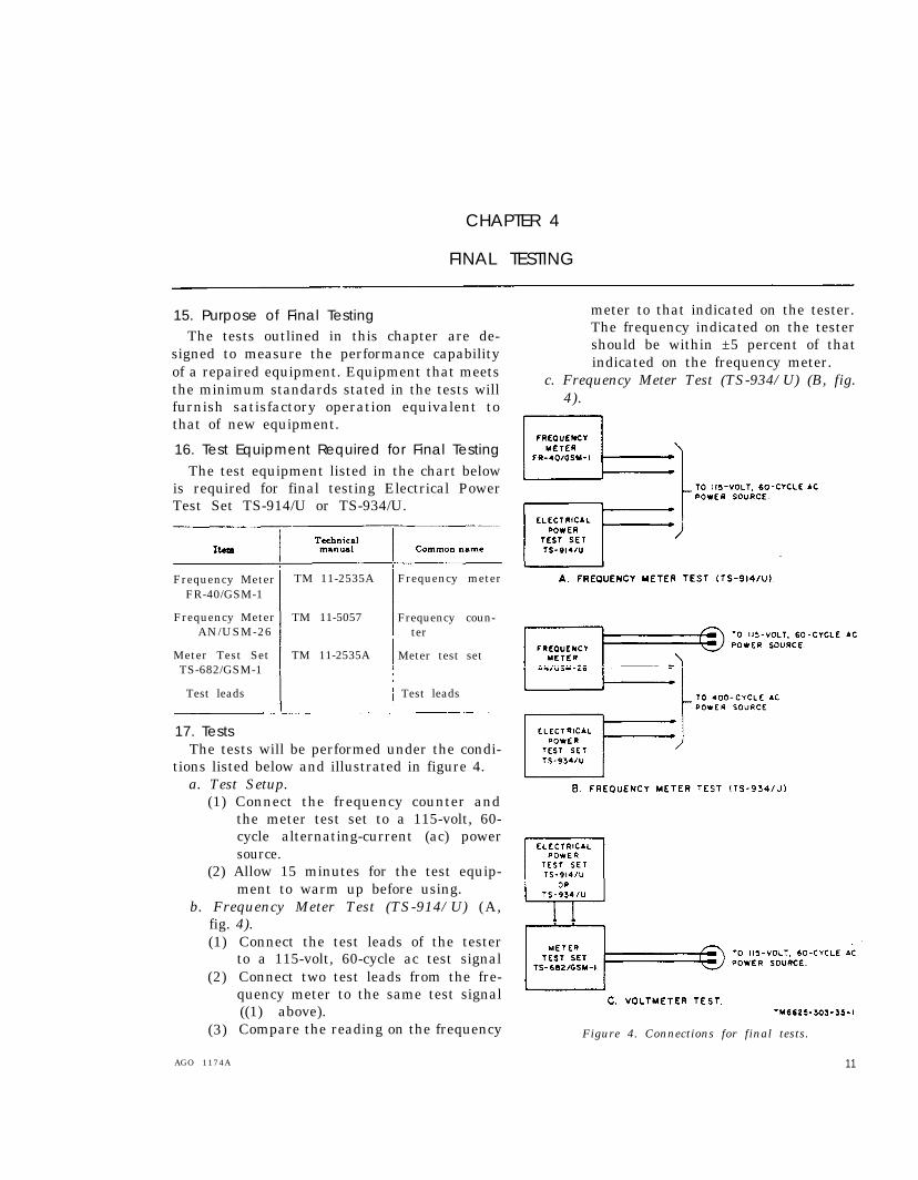
17. TestsThe tests will be performed under the condi-
tions listed below and illustrated in figure 4.a. Test Setup.
(1) Connect the frequency counter andthe meter test set to a 115-volt, 60-cycle alternating-current (ac) powersource.
(2) Allow 15 minutes for the test equip-ment to warm up before using.
b. Frequency Meter Test (TS-914/U) (A,fig. 4).(1)
(2)
(3)
AGO 1174A
Connect the test leads of the testerto a 115-volt, 60-cycle ac test signalConnect two test leads from the fre-quency meter to the same test signal((1) above).Compare the reading on the frequency
meter to that indicated on the tester.The frequency indicated on the testershould be within ±5 percent of thatindicated on the frequency meter.
c. Frequency Meter Test (TS-934/U) (B, fig.4).
Figure 4. Connections for final tests.
11

(1)
(2)
(3)
Connect the SIGNAL INPUT jack onthe frequency counter to a 400-cyc1etest signal source.
Connect the tester to the same source.
Compare the reading on the fre-quency counter to the reading on thetester. The frequency indicated on thetester should be within ± 5 percent ofthat indicated on the frequencycounter.
d. Voltmeter test (C, fig. 4).Note. Connect the alligator clips to the test prods
of the tester.
(1)
(2)
Set up the meter test set to indicateac voltage.Connect the spade-lug end of the testcord that has Plug PL-55 at the otherend to either test prod of the tester.Connect one end of the cord that hasa spade-lug at each end to the other
test prod. Connect the other spade-lug to the COMMON binding post onthe meter test set.
(3) Check to see that the voltmeterpointer is directly over zero. Zeroadjust the voltmeter (TM 11-6625-303-12) if necessary.
(4) Insert Plug PL-55 into the appropri-ate ac VOLTS jack on the front panelof the meter test set.
(5) Compare the reading on the testervoltmeter with the reading on thestandard ac meter of the meter testset.
(6) The full scale reading on the testershould be within ±2 percent of thereading on the meter test set stand-ard (within 3 volts on the zero to150-volt scale; within 6 volts on thezero to 300-volts scale).
12 AGO 1174A

APPENDIX
REFERENCES
Following is a list of applicable references TM 11-6625-303-12.
available to the field and depot maintenance
repairman of Electrical Power Test Sets AN/
UPM-93 and AN/UPM-100:TM 11-2535A . . . . . . . . . .
TM 11-5057 . . . . . . . . . . . .
[AG 413.44 (23 July 1959)]
Electrical Power Test Sets AN/U P M - 9 3 a n d A N / U P M - 1 0 0Operation and OrganizationalMaintenance.
Meter Test Equipments AN/GSM-1B and AN/GSM-1C.
Frequency Meter AN/USM-26.
B Y O R D E R O F T H E S E C R E T A R I E S O F T H E A R M Y A N D T H E A I R F O R C E:
O F F I C I A L:
R . V . L E E ,Major General, United States
The Adjutant General.
OFFICIAL:
J. L. TARR,Colonel, United States Air
L. L. LEMNITZER,General, United States Army,
Chief of Staff.
Army,
THOMAS D. WHITE,Chief of Staff, United States Air Force.
Force,Director of Administrative Services.
DISTRIBUTION :
Active Army:
USASA (2)
Def Atomic Spt Agcy (5)
CNGB (1)
Tech Stf, DA (1) except
CSigO (30)
Tech Stf Bd (1)
USA Arty Bd (1)
USA Armor Bd (1)
USA Inf Bd (1)
USA AD Bd (1)
USA Abn & Elct Bd (1)
USA Avn Bd (1)
USA ATB (1)
USCONARC (5)
US ARADCOM (2)
US ARADCOM Rgn (2)
AGO 1174A
OS Maj Cored (5)
OS Base Cored (6)
Log Cored (5)
MDW (1)
Armies (5) except
First US Army (7)
Corps (2)
Div (2)
USATC (2)
Svc Colleges (5)
Br Svc Sch (5) except
USASCS (25)
Gen Dep (2)
Sig Sec Gen Dep (12)
Sig Dep (19)
Army Pictorial Cen (2)
Engr Maint Cen (1)
USA Ord Msl Cored (3)
USASSA (15)
13

14
U S AS S A M R O ( 1 )
USA Sig Pub Agcy (8)
USA S ig Engr Agcy (1 )
USA Comm Agcy (2)
USA Sig Eqp Spt Agcy (7)
USA Sig Msl Spt Agcy (13)
W R A M C ( 1 )
A F I P ( 1 )
A M S ( 1 )
Ports of Emb (OS) (2)
Trans Terminal Comd (1)
Army Terminals (1)
O S SU P Agcy (1 )
Yuma Test Sta (2)
USA Elct PG (1)
Sig Lab (5)
Sig Fld Maint Shops (3)
Mil Dist (1)
USA Corps (Res ) (1 )
Sector Comd, USA Corps (Res) (1)
JBUSMC (2)
Units org under fol TOE:
11-7 (2)
11-16 (2)
11-57 (2)
11-97 (2)
11-117 (2)
11-155 (2)
11 -500 (AA-AE) (2 )11-557 (2)11-587 (2)11-592 (2)11-597 (2)
NG: State AG (3) ; units-same as Active Army except allowance is one copy
USAR: None. For explanation of abbreviations used, see AR 320-50.
to each u n i t .
AGO 1174A
‘.s. 60 VERNMENT P@ INr INe OFFICE: Iqs6 - ,?t-azl,coe’s


PIN: 017078-001

This fine document...
Was brought to you by me:
Liberated Manuals -- free army and government manuals
Why do I do it? I am tired of sleazy CD-ROM sellers, who take publicly available information, slap “watermarks” and other junk on it, and sell it. Those masters of search engine manipulation make sure that their sites that sell free information, come up first in search engines. They did not create it... They did not even scan it... Why should they get your money? Why are not letting you give those free manuals to your friends?
I am setting this document FREE. This document was made by the US Government and is NOT protected by Copyright. Feel free to share, republish, sell and so on.
I am not asking you for donations, fees or handouts. If you can, please provide a link to liberatedmanuals.com, so that free manuals come up first in search engines:
<A HREF=http://www.liberatedmanuals.com/>Free Military and Government Manuals</A>
– SincerelyIgor Chudovhttp://igor.chudov.com/
– Chicago Machinery Movers