electrical power and energy systems - dso-power.com
TRANSCRIPT

Electrical Power and Energy Systems 41 (2012) 34–43
Contents lists available at SciVerse ScienceDirect
Electrical Power and Energy Systems
journal homepage: www.elsevier .com/locate / i jepes
Load compensation using DSTATCOM in three-phase, three-wire distribution systemunder various source voltage and delta connected load conditions
Tejas Zaveri a,⇑, B.R. Bhalja b, Naimish Zaveri c
a Faculty of Engineering & Technology, Veer Narmad South Gujarat University, Surat 395 007, Gujarat, Indiab Department of Electrical Engineering, A.D. Patel Institute of Technology, New Vallabh Vidyanagar 388 121, Gujarat, Indiac Electrical Engineering Department, C.K. Pithawalla College of Engineering & Technology, Surat 395 007, Gujarat, India
a r t i c l e i n f o
Article history:Received 25 October 2011Received in revised form 19 December 2011Accepted 5 February 2012Available online 15 March 2012
Keywords:DSTATCOMIARCC theoryPower factor correctionSource VA reductionLoad balancingHarmonic mitigation
0142-0615/$ - see front matter � 2012 Elsevier Ltd. Adoi:10.1016/j.ijepes.2012.02.015
⇑ Corresponding author. Tel.: +91 9909110232.E-mail addresses: [email protected] (T. Zaver
(B.R. Bhalja), [email protected] (N. Zaveri).
a b s t r a c t
This paper deals with a Distribution STATic COMpensator (DSTATCOM) for balancing of source currents,power factor correction and harmonic mitigation in three-phase, three-wire distribution system supply-ing delta connected load under various source voltage conditions. The control strategy applied to theDSTATCOM play a major role in its performance. A novel approach based on an improved instantaneousactive and reactive current component (IARCC) theory is proposed for generation of three-phase refer-ence currents for DSTATCOM. A three-phase voltage source converter with a dc bus capacitor is employedas DSTACOM which will track the reference currents in a hysteresis band scheme. The performance ofDSTATCOM is evaluated under sinusoidal, unbalanced sinusoidal and unbalanced distorted sourcevoltage conditions. Variation in load current, variation in magnitude and harmonic content in sourcevoltage has been considered. Delta connected linear as well as non-linear load conditions have beenconsidered. The performance of the DSTATCOM using the proposed control strategy is demonstratedusing simulation results in MATLAB/SIMULINK software. Simulation results demonstrate the feasibilityof proposed scheme for the control of DSTACOM.
� 2012 Elsevier Ltd. All rights reserved.
1. Introduction
Nowadays, the power quality in the distribution system is con-taminated due to high reactive power burden, distorted and unbal-ance load currents [1–3]. Due to excessive reactive power demand,there is an increase in transmission & distribution losses andreduction in active power flow capability of the distribution sys-tem. Further, the operation of transformers and generators are alsoaffected due to unbalancing of currents and it also increases thesize of utility [4]. Therefore, reactive power compensation ofnon-linear and/or poor power factor loads and load balancing isan important issue in the modern power distribution system. Thepower indices are governed by various standards such as IEEE-519 standard [5]. The remedies to power quality problems are re-ported in literature and are known by the generic name of custompower devices [3].
Dynamic voltage restorer (DVR) is a custom power device con-nected in series with the load. The basic principle of a DVR is basedon restoration of the load side voltage to the desired amplitude andwaveform irrespective of unbalance or distortion in either source
ll rights reserved.
or load side by inserting a voltage of required magnitude and fre-quency. Thus, it protects sensitive load from the effect of unbalanceand/or distortion in the supply side voltage [6]. Therefore, DVR isnot suitable to serve objectives such as harmonic mitigation insource currents due to non-linear load, imbalance elimination ofunbalanced loads, supply power factor correction and source VAreduction under various source voltage and load conditions. Con-versely, DSTATCOM is a custom power device connected in shuntwith the load. It injects currents in the ac system such that the loadcompensation is achieved irrespective of unbalance or distortion ineither source or load side. Moreover, it is operated in current con-trol mode to compensate the effect of load currents under varioussource voltage conditions. Further, it is very effective in balancingof any unbalance in load currents and also for cleaning pollution inthe load. In this way, it protects the utility system from the ill ef-fects of customer loads [6].
DSTATCOM has been used extensively for reactive power com-pensation, balancing of source currents and harmonic compensa-tion in the distribution system [7]. The performance ofDSTATCOM depends on the reference current generation tech-nique. To serve this purpose, many control algorithms have beenpresented by various researchers. These algorithms are based oninstantaneous reactive power theory, synchronous reference frametheory (SRF), symmetrical component theory, current compensa-tion technique using dc bus voltage regulation, computation tech-
Nomenclature
Vsa/b/c source voltage of phase-a, phase-b and phase-crespectively
isa/b/c source current of phase-a, phase-b and phase-crespectively
ilab/bc/ca load currentsistab/bc/ca compensator currents� over the letter: variable part– over the letter: average value
Subscriptd d component in odq coordinates systemq q component in odq coordinates system
a a component in 0ab coordinates systemaF a component in 0ab coordinates system after filtrationb b component in 0ab coordinates systembF b component in 0ab coordinates system after filtration1h fundamental componentnh nth harmonic component
Superscript+ positive sequence component� negative sequence component⁄ reference component
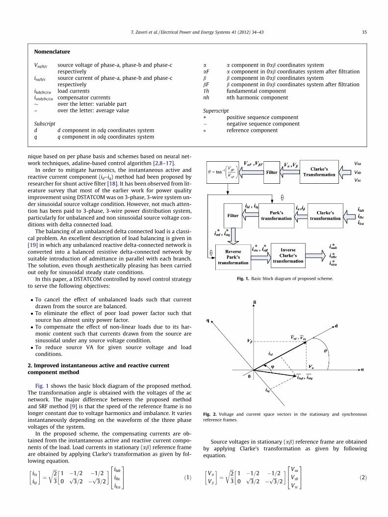
Fig. 1. Basic block diagram of proposed scheme.
Fig. 2. Voltage and current space vectors in the stationary and synchronousreference frames.
T. Zaveri et al. / Electrical Power and Energy Systems 41 (2012) 34–43 35
nique based on per phase basis and schemes based on neural net-work techniques, adaline-based control algorithm [2,8–17].
In order to mitigate harmonics, the instantaneous active andreactive current component (id–iq) method had been proposed byresearcher for shunt active filter [18]. It has been observed from lit-erature survey that most of the earlier work for power qualityimprovement using DSTATCOM was on 3-phase, 3-wire system un-der sinusoidal source voltage condition. However, not much atten-tion has been paid to 3-phase, 3-wire power distribution system,particularly for unbalanced and non sinusoidal source voltage con-ditions with delta connected load.
The balancing of an unbalanced delta connected load is a classi-cal problem. An excellent description of load balancing is given in[19] in which any unbalanced reactive delta-connected network isconverted into a balanced resistive delta-connected network bysuitable introduction of admittance in parallel with each branch.The solution, even though aesthetically pleasing has been carriedout only for sinusoidal steady state conditions.
In this paper, a DSTATCOM controlled by novel control strategyto serve the following objectives:
� To cancel the effect of unbalanced loads such that currentdrawn from the source are balanced.� To eliminate the effect of poor load power factor such that
source has almost unity power factor.� To compensate the effect of non-linear loads due to its har-
monic content such that currents drawn from the source aresinusoidal under any source voltage condition.� To reduce source VA for given source voltage and load
conditions.
2. Improved instantaneous active and reactive currentcomponent method
Fig. 1 shows the basic block diagram of the proposed method.The transformation angle is obtained with the voltages of the acnetwork. The major difference between the proposed methodand SRF method [9] is that the speed of the reference frame is nolonger constant due to voltage harmonics and imbalance. It variesinstantaneously depending on the waveform of the three phasevoltages of the system.
In the proposed scheme, the compensating currents are ob-tained from the instantaneous active and reactive current compo-nents of the load. Load currents in stationary (ab) reference frameare obtained by applying Clarke’s transformation as given by fol-lowing equation.
ila
ilb
� �¼
ffiffiffi23
r1 �1=2 �1=20
ffiffiffi3p
=2 �ffiffiffi3p
=2
� � ilab
ilbc
ilca
264
375 ð1Þ
Source voltages in stationary (ab) reference frame are obtainedby applying Clarke’s transformation as given by followingequation.
Va
Vb
� �¼
ffiffiffi23
r1 �1=2 �1=20
ffiffiffi3p
=2 �ffiffiffi3p
=2
� � Vsa
Vsb
Vsc
264
375 ð2Þ

36 T. Zaveri et al. / Electrical Power and Energy Systems 41 (2012) 34–43
In order to calculate the transformation angle, source voltagesin stationary (ab) reference frame given by Eq. (2) are filtered bylow pass filters. Source voltages in stationary reference frame afterfiltering are denoted by VaF and VbF. The use of the low pass filtermakes the strategy more insensitive to harmonics on the mains.
The magnitude response of Butterworth low-pass filter is givenby,
jHðjxÞj ¼ A
1þ ðX=XCÞ2Nh i0:5
where A is the filter gain and XC is the 3 dB cut-off frequency and Nis the order of the filter.
The transfer function of the Butterworth filter is usually writtenin the factored form as given below
HðSÞ ¼YN=2
K¼1
BkX2C
s2 þ bkXCsþ ckX2C
N ¼ 2;4;6; . . .
Fig. 3. (a) Basic compensator scheme and (b) system con
or
HðSÞ ¼ B0XC
sþ c0XC
YðN�1Þ=2
K¼1
BkX2C
s2 þ bkXCsþ ckX2C
N ¼ 3;5;7; . . .
The coefficients bk and ck are given by,
bk ¼ 2 sin½ð2k� 1Þp=2N� and Ck ¼ 1
The parameters Bk can be obtained from the followingequations.
A ¼YN=2
K¼1
BK ; for evenN
and
A ¼YðN�1Þ=2
K¼1
BK ; for oddN
figuration with practical realization of compensator.

T. Zaveri et al. / Electrical Power and Energy Systems 41 (2012) 34–43 37
Load currents in rotating (dq) reference frame are obtained byapplying Park’s transformation as shown in following equation.
ild
ilq
� �¼
cos h sin h
� sin h cos h
� �ila
ilb
� �; h ¼ tan�1 VbF
VaF
� �ð3Þ
Fig. 2 depicts the voltage and current space vectors in the sta-tionary (ab) and rotating reference frames (dq). Under balancedand sinusoidal mains voltage conditions, the transformation angleh is a function of time and it increases uniformly. Therefore, dh/dtdoes not remain constant over a period of supply voltage. Now,due to transformation, the direct and the quadrature componentsof voltage are given by,
Vd ¼ jVdqj ¼ jVabj ¼ffiffiffiffiffiffiffiffiffiffiffiffiffiffiffiffiffiffiffiffiffiV2
aF þ V2bF
qand Vq ¼ 0:
If d-axis is in the direction of the voltage space vector then thetransformation is given by Eq. (4). This is achieved by substitutingcos h ¼ VaFffiffiffiffiffiffiffiffiffiffiffiffiffi
V2aFþV2
bF
p and sin h ¼ VbFffiffiffiffiffiffiffiffiffiffiffiffiffiV2
aFþV2bF
p into following equation.
ild
ilq
� �¼ 1ffiffiffiffiffiffiffiffiffiffiffiffiffiffiffiffiffiffiffiffiffi
V2aF þ V2
bF
q VaF VbF
�VbF VaF
� �ila
ilb
� �ð4Þ
Instantaneous active and reactive load currents in rotating ref-erence frame, ild and ilq can be decomposed into oscillatory andaverage terms as under.
Fig. 4. DSTATCOM performance for linear balanced load under case A: (a) three-phase souncompensated source current of phase-a, (d) source voltage and uncompensated source(f) three-phase load currents, (g) three-phase uncompensated source currents, (h) FFcompensated source current of phase-a, (j) source voltage and compensated source curthree-phase source currents after compensation, (m) FFT spectrum of compensated sou
ild ¼ �ild þ~ild and ilq ¼ �ilq þ~ilq:
The positive sequence component of first harmonic current istransformed into dc quantities (iþldq1h) which constitutes the aver-age current components. All higher order current harmonicsincluding the negative sequence component of first harmoniccurrent (i�ldqnh þ i�ldq1h) are transformed into non-dc quantities andundergo a frequency shift in the spectra. Hence, they constitutethe oscillatory current components. The fundamental currents ofd–q components are now dc values and harmonics are going to ap-pear like a ripple. Harmonic isolation of d–q transformed signal isachieved by removing the dc offset. After eliminating the averagecurrent components by filters, the reference compensator currentsare obtained as under.
i�std ¼ �~ild and i�std ¼ �~ilq
Therefore, the reference currents of voltage source converter inthe ab coordinates are obtained by applying Inverse Park transfor-mation and given by following equation.
i�sta
i�stb
24
35 ¼ 1ffiffiffiffiffiffiffiffiffiffiffiffiffiffiffiffiffiffiffiffiffi
V2aF þ V2
bF
q VaF �VbF
VbF VaF
" #i�std
i�stq
24
35 ð5Þ
urce voltages, (b) FFT spectrum of source voltage of phase-a, (c) source voltage andcurrent of phase-b, (e) source voltage and uncompensated source current of phase-c,T spectrum of uncompensated source current of phase-a, (i) source voltage andrent of phase-b, (k) source voltage and compensated source current of phase-c, (l)rce current of phase-a, (n) three-phase compensator currents.

38 T. Zaveri et al. / Electrical Power and Energy Systems 41 (2012) 34–43
Applying Inverse Clarke’s transformation, the reference currentsof voltage source converter in abc frame are given by followingequation.
i�stab
i�stbc
i�stca
264
375 ¼
ffiffiffi23
r1 �1=2 �1=20
ffiffiffi3p
=2 �ffiffiffi3p
=2
� �T i�sta
i�stb
" #ð6Þ
3. System configuration
The basic compensator scheme for delta connected load isshown in Fig. 3a. Fig. 3b shows the system configuration withthe practical realization of the compensator for the proposedscheme. The compensator can be implemented by a three-phasevoltage source converter (VSC) which has been operated in hyster-esis band control scheme to track reference currents generated bythe proposed control algorithm.
The structure of the compensator contains a bank of three sin-gle-phase VSC units. Three single-phase voltage source convertersare connected to a common dc storage capacitor. Each VSC unit isconnected through an isolating transformer which provides isola-tion between the converters. In Fig. 3b, controlled switch is apower semiconductor device and anti-parallel diode combination.Transformer also prevents the dc storage capacitor from beingshorted through controlled switches in different converters. It isto be noted that the capacitor must be pre-charged to sufficientlyhigh value in order to obtain satisfactory tracking performance.However, increasing the capacitor voltage increases the losses inthe system. Therefore, the level of capacitor voltage must be cho-
Fig. 5. DSTATCOM performance for non-linear unbalanced load under case A: (a) threvoltage and uncompensated source current of phase-a, (d) source voltage and uncompcurrent of phase-c, (f) FFT spectrum of uncompensated source current of phase-a, (g) scompensated source current of phase-b, (i) source voltage and compensated source currencompensated source current of phase-a, (l) three-phase compensator currents.
sen judiciously. Lf represents the inductance of each transformeras well as an additional interfacing inductance. It has been usedto filter out high-frequency components of compensating currents.It also controls the switching frequency of the inverter which islimited by the speed of switching devices and the power level.
4. Performance evaluation
The proposed control algorithm is validated using MATLAB/SIMPOWER software. In this section, simulation results of three-phase, three-wire system supplying delta connected linear/non-linear load under various source voltage conditions are presented.Linear load is realized by resistive-inductive load whereas non-lin-ear load is simulated by three-phase rectifier with RLC load. Thesystem parameters are given in Appendix A.
Simulation study has been carried out with linear/non-linearload under three different source voltage conditions:
Case A: ideal source voltage.Case B: unbalanced sinusoidal source voltage.Case C: unbalanced distorted source voltage.
In order to plot source voltages and currents on the same scale,source voltages are scaled down by a factor of 10 and 2 for linearand non-linear load, respectively.
4.1. Ideal source voltage (Case A)
For balanced sinusoidal source voltage condition, performanceof DSTATCOM with linear and non-linear load is shown in Figs. 4
e-phase source voltages, (b) FFT spectrum of source voltage of phase-a, (c) sourceensated source current of phase-b, (e) source voltage and uncompensated sourceource voltage and compensated source current of phase-a, (h) source voltage andt of phase-c, (j) three-phase source currents after compensation, (k) FFT spectrum of

Fig. 6. DSTATCOM performance for linear unbalanced load under case B:(a) three-phase source voltages, (b) FFT spectrum of source voltage of phase-a, (c) source voltage anduncompensated source current of phase-a, (d) source voltage and uncompensated source current of phase-b, (e) source voltage and uncompensated source current of phase-c,(f) three-phase load currents, (g) three-phase uncompensated source currents, (h) FFT spectrum of source current of phase-a, (i) source voltage and compensated sourcecurrent of phase-a, (j) source voltage and compensated source current of phase-b, (k) source voltage and compensated source current of phase-c, (l) three-phase sourcecurrents after compensation, (m) FFT spectrum of compensated source current of phase-a, (n) three-phase compensator currents.
Fig. 7. DSTATCOM performance for non-linear unbalanced load under case B:(a) three-phase source voltages, (b) FFT spectrum of source voltage of phase-a, (c) source voltageand uncompensated source current of phase-a, (d) source voltage and uncompensated source current of phase-b, (e) source voltage and uncompensated source current ofphase-c, (f) FFT spectrum of uncompensated source current of phase-a, (g) source voltage and compensated source current of phase-a, (h) source voltage and compensatedsource current of phase-b, (i) source voltage and compensated source current of phase-c, (j) three-phase source currents after compensation, (k) FFT spectrum of compensatedsource current of phase-a, (l) three-phase compensator currents.
T. Zaveri et al. / Electrical Power and Energy Systems 41 (2012) 34–43 39

40 T. Zaveri et al. / Electrical Power and Energy Systems 41 (2012) 34–43
and 5, respectively. For linear load, balanced load currents havebeen considered. It has been observed from Fig. 4 that underuncompensated condition, source voltage is not in alignment withsource current. It indicates that reactive power is supplied bysource. Correction in supply power factor can be observed aftercompensation. We can observe reduction in magnitude of sourcecurrents compared to uncompensated source currents. With refer-ence to Fig. 5, it is to be noted that source currents have becomealmost sinusoidal for highly distorted load currents. Compensatedsource current consist of only fundamental component where asno. of harmonics are present in uncompensated source currents.Moreover, balancing of source currents and unity power factorare obtained. Only average component of load power is suppliedby source.
4.2. Unbalanced sinusoidal source voltage (Case B)
The magnitude of source voltage of phase-a is 20% smaller thansource voltage of phase-b and phase-c. Simulation results of case Bwith linear and non-linear unbalanced load are shown in Figs. 6and 7, respectively. It is to be noted from Figs. 6 and 7 that irre-spective of unbalancing in source voltages, it is possible to achievepower factor correction, reduction in magnitude of source currentsand balancing of source currents. Effect of unbalance in sourcevoltages is observed in compensator currents compared to caseA. In case of non-linear load, it can be observed from FFT spectrum
Fig. 8. DSTATCOM performance for linear unbalanced load under case C:(a) three-phasesource voltage of phase-b, (d) FFT spectrum of source voltage of phase-c, (e) sourceuncompensated source current of phase-b, (g) source voltage and uncompensated sospectrum of uncompensated source current of phase-a, (j) source voltage and compensatphase-b, (l) source voltage and compensated source current of phase-c, (m) three-phase sof phase-a, (o) FFT spectrum of compensated source current of phase-b, (p) FFT spectrum
that odd order harmonics are present in uncompensated sourcecurrents whereas only fundamental component is present in com-pensated source current. Thus, harmonic mitigation is achievedeffectively which results in sinusoidal source currents.
4.3. Unbalanced distorted source voltage (Case C)
For this case, source voltages are unbalanced and distorted. Themagnitude of source voltage of phase-a is 20% smaller than therated source voltage. Fifth harmonic with amplitude 1/10 andseventh harmonic component with amplitude of 1/14 of therated source voltage are present in source voltage of phase-a andphase-b, respectively. Moreover, Fifth harmonic and seventhharmonic with their amplitudes same as in phase-a and phase-b,respectively are simultaneously present in source voltage ofphase-c. Figs. 8 and 9 show the simulation results of DSTATCOMfor linear and non-linear unbalanced load, respectively. For non-linear unbalance load, both source voltages and load currents aredistorted and unbalanced. Hence, the condition has become morecritical. It has been observed from Figs. 8 and 9 that source currentsbecome almost equal in magnitude. It can be noted from FFTspectrum of compensated source current that only fundamentalcomponent is present in source current after compensation. Thus,irrespective of variation in harmonic content in each phaseof source voltage, harmonic mitigation is effectively achieved.Further, due to reduction in magnitude of compensated source
source voltages, (b) FFT spectrum of source voltage of phase-a, (c) FFT spectrum ofvoltage and uncompensated source current of phase-a, (f) source voltage and
urce current of phase-c, (h) three-phase uncompensated source currents, (i) FFTed source current of phase-a, (k) source voltage and compensated source current ofource currents after compensation, (n) FFT spectrum of compensated source current
of compensated source current of phase-c, (q) three-phase compensator currents.
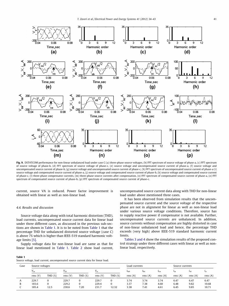
Fig. 9. DSTATCOM performance for non-linear unbalanced load under case C:(a) three-phase source voltages, (b) FFT spectrum of source voltage of phase-a, (c) FFT spectrumof source voltage of phase-b, (d) FFT spectrum of source voltage of phase-c, (e) source voltage and uncompensated source current of phase-a, (f) source voltage anduncompensated source current of phase-b, (g) source voltage and uncompensated source current of phase-c, (h) FFT spectrum of uncompensated source current of phase-a (i)source voltage and compensated source current of phase-a, (j) source voltage and compensated source current of phase-b, (k) source voltage and compensated source currentof phase-c, (l) three-phase compensator currents, (m) three-phase source currents after compensation, (n) FFT spectrum of compensated source current of phase-a, (o) FFTspectrum of compensated source current of phase-b, (p) FFT spectrum of compensated source current of phase-c.
T. Zaveri et al. / Electrical Power and Energy Systems 41 (2012) 34–43 41
current, source VA is reduced. Power factor improvement isobtained with linear as well as non-linear load.
4.4. Results and discussion
Source voltage data along with total harmonic distortion (THD),load currents, uncompensated source current data for linear loadunder three different cases, as discussed in the previous sub-sec-tions are shown in Table 1. It is to be noted from Table 1 that thepercentage THD for unbalanced distorted source voltage (case C)is above 7% which is higher than IEEE-519 standard harmonic volt-age limits [5].
Supply voltage data for non-linear load are same as that forlinear load mentioned in Table 1. Table 2 show load current,
Table 1Source voltage, load current, uncompensated source current data for linear load.
Case Source voltages
Vsa Vsb Vsc
rms (V) THD (%) rms (V) THD (%) rms (V) THD (%
A 229.7 0 229.7 0 229.7 0B 183.6 0 229.2 0 229.4 0C 185.4 12.5 230.6 7.20 231.7 12.32
uncompensated source current data along with THD for non-linearload under above mentioned three cases.
It has been observed from simulation results that the uncom-pensated source current and the source voltage of the respectivephase are not in alignment for linear as well as non-linear loadunder various source voltage conditions. Therefore, source hasto supply reactive power if compensator is not available. Further,uncompensated source currents are unbalanced. In addition,source currents without compensation are highly distorted in caseof non-linear unbalanced load and hence, the percentage THDexceeds (very high) above IEEE-519 standard harmonic currentlimits.
Tables 3 and 4 show the simulation results of the proposed con-trol strategy under three different cases with linear as well as non-linear load, respectively.
Load currents Source currents
ilab ilbc ilca isa isb isc
) rms (A) rms (A) rms (A) rms (A) rms (A) rms (A)
3.74 3.74 3.74 6.47 6.47 6.473.37 7.38 4.60 6.48 9.82 10.683.38 7.41 4.61 6.45 9.85 10.71

Table 3Summary of simulation results of the proposed control strategy with linear load under three cases.
Case Source currents Compensator currents
isa isb isc istab istbc istca
rms (A) THD (%) rms (A) THD (%) rms (A) THD (%) rms (A) rms (A) rms (A)
A 3.63 4.12 3.62 4.23 3.60 4.23 10.62 10.27 10.4B 4.91 4.60 5.91 4.31 4.96 4.86 13.75 11.58 15.36C 5.02 4.99 5.27 4.09 4.91 4.64 12.49 11.60 13.52
Table 4Summary of simulation results of the proposed control strategy with non-linear unbalanced load under three cases.
Case Source currents Compensator currents
isa isb isc istab istbc istca
rms (A) THD (%) rms (A) THD (%) rms (A) THD (%) rms (A) rms (A) rms (A)
A 32.74 1.96 33.28 2.25 32.69 2.28 15.37 22.39 17.38B 28.63 3.24 31.12 2.71 28.99 3.55 13.89 22.94 15.14C 30.89 3.30 33.34 3.02 31.28 3.74 16.83 26.65 16.09
Table 2Load current, uncompensated source current data for non-linear load.
Case Load currents Source currents
ilab ilbc ilca isa isb isc
rms (A) THD (%) rms (A) THD (%) rms (A) THD (%) rms (A) THD (%) rms (A) THD (%) rms (A) THD (%)
A 15.69 118.13 30.1 102.91 22.03 110.02 27.04 73.43 33.95 73.83 37.3 64.72B 14.13 118.08 30.11 102.99 19.88 109.99 24.39 81.15 33.26 72.15 36.09 62.27C 16.92 146.46 34.14 119.17 20.82 119.86 26.83 87.87 38.1 94.38 39.98 83.30
42 T. Zaveri et al. / Electrical Power and Energy Systems 41 (2012) 34–43
With reference to Tables 3 and 4, following observations aremade for compensated system with delta connected linear/non-linear load under various source voltage conditions:
(i) Power factor correction is achieved for linear load. It resultsin reduction in reactive power supplied from source.
(ii) Unity source power factor is attained for non-linear load.Hence, source has to supply only average power to the load.
(iii) Balancing of source currents is achieved under all mentionedsource voltage conditions.
(iv) The source VA is reduced due to reduction in rms value ofsource current after compensation.
(v) THD of compensated source current is within IEEE-519standard harmonic current limits under various sourcevoltage conditions.
5. Conclusion
In this paper, a scheme based on an improved instantaneous ac-tive and reactive current component theory is proposed for DSTAT-COM installed in three-phase, three-wire system. The performanceof the proposed scheme has been evaluated under balancedsinusoidal, unbalanced sinusoidal and unbalanced nonsinusoidalsource voltage conditions in which delta connected linear as wellas non-linear load situations are taken into account. The proposedscheme has been validated on a three-phase, three-wire distributionsystem using MATLAB/SIMULINK software. The simulation resultsshowed that, if one seeks compliance with harmonics standards,imbalance elimination, power factor correction and source VAreduction, proposed scheme is capable of taking correct action undervarious source voltage and load conditions. In addition, the proposedscheme is capable to restrict THD of source current within IEEE-519standard harmonic current limits under any condition of use.
Appendix A
System parameters
Rated source voltage 230 V (rms value). Supply frequency 50 Hz Source parameters Rs = 0.1 X, Ls = 0.01 mH Compensatorparameters
Vdc = 600 V, Cdc = 1000 lF, R = 0.5 X,Lf = 6 mH. The turn ratio of eachtransformer is assumed to be 1:1Linear load
Case A: Rlab = 75 X, Llab = 240 mH. Case B and Case C: Rlab = 75 X,Llab = 240 mH, Rlbc = 35 X,Llbc = 130 mH, Rlca = 50 X,Llca = 190 mHNon-linear load
Case A, B, C: L = 1 mH, C = 1000 lF,Rlab = 75 X, Rlbc = 35 X and Rlca = 50 XReferences
[1] Acha E, Agelids V, Anaya-Lara O, Miller T. Power electronic control in electricsystems. 1st ed. Newness power engineering series. Oxford; 2002.
[2] Akagi H, Watanabe EH, Aredes M. Instantaneous power theory andapplications to power conditioning. New Jersey, USA: John Wiley & Sons; 2007.
[3] Fuchs Ewald F, Mausoum Mohammad AS. Power quality in power systems andelectrical machines. London, UK: Elsevier Academic Press; 2008.
[4] Moreno-Munoz A. Power quality: mitigation technologies in a distributedenvironment. London: Springer-Verlag London limited; 2007.
[5] IEEE recommended practices and requirements for harmonics control inelectric power systems. IEEE Std. 519; 1992.
[6] Ghosh A, Ledwich G. Power quality enhancement using custom powerdevices. Boston: Kluwer Academic Publishers; 2002.
[7] Chen B, Hsu Y. A minimal harmonic controller for a STATCOM. IEEE Trans IndElectron 2008;55(2):655–64.

T. Zaveri et al. / Electrical Power and Energy Systems 41 (2012) 34–43 43
[8] Herrera RS, Salmeron P, Kim H. Instantaneous reactive power theory applied toactive power filter compensation: different approaches, assessment, andexperimental results. IEEE Trans Ind Electron Jan. 2008;55(1):184–96.
[9] Divan D, Bhattacharya S, Banarjee B. Synchronous frame harmonic isolatorusing active series filter. In: Proceedings of 4th European conference on powerelectronics and applications, Florence, Italy; 3–6 September, 1991. p. 3030–5.
[10] Ghosh A, Joshi A. The use of instantaneous symmetrical components forbalancing a delta connected load and power factor correction. Electr PowerSyst Res 2000;54:67–74.
[11] Singh B, Verma V. Selective compensation of power-quality problems throughactive power filter by current decomposition. IEEE Trans Power Deliv2008;23(2):792–9.
[12] Lascu C, Asiminoaei L, Boldea I, Blaabjerg F. Frequency response analysis ofcurrent controllers for selective harmonic compensation in active powerfilters. IEEE Trans Ind Electron 2009;56(2):337–47.
[13] Luo A, Shuai Z, Zhu W, Shen ZJ. Combined system for harmonic suppressionand reactive power compensation. IEEE Trans Ind Electron2009;56(2):418–28.
[14] Shyu K-K, Yang M-J, Chen Y-M, Lin Y-F. Model reference adaptive controldesign for a shunt active-power-filter system. IEEE Trans Ind Electron2008;55(1):97–106.
[15] Mohagheghi S, Valle Y, Venayagamoorthy GK, Harley RG. A proportional-integrator type adaptive critic design-based neurocontroller for a staticcompensator in a multimachine power system. IEEE Trans Ind Electron Feb.2007;54(1):86–96.
[16] Shu Z, Guo Y, Lian J. Steady-state and dynamic study of active power filter withefficient FPGA-based control algorithm. IEEE Trans Ind Electron2008;55(4):1527–36.
[17] Singh B, Solanki J. A comparison of control algorithms for DSTATCOM. IEEETrans Ind Electron 2009;56(7).
[18] Soares V, Verdelho P, Marques G. An instantaneous active and reactive currentcomponent method for active filters. IEEE Trans Power Electron July2000;15(4):660–9.
[19] Miller TJ. Reactive power control in electric systems. 1st ed. Willey-Interscience: New York; 1982.