electrical planning and design guide
TRANSCRIPT

Planning and Design Guide
FOD-Utilities High Voltage
9/24/2014

PLANNING and DESIGN GUIDE final.docx September 2014
The Ohio State University, FOD – Utilities, UTHVS Page 1 of 186
Table of Contents
1 Introduction .......................................................................................................................................... 4
1.1 Campus Planning ........................................................................................................................... 4
1.2 BDS Requirements and Basis ........................................................................................................ 4
1.3 General Design Criteria ................................................................................................................. 4
1.4 Detailed Design Criteria ................................................................................................................ 4
1.5 Authority Having Jurisdiction ........................................................................................................ 4
1.6 Design Control ............................................................................................................................... 6
2 Organization and Maintenance ............................................................................................................ 8
3 Bulk Power Planning Study ................................................................................................................... 8
4 Distribution System Planning Study ...................................................................................................... 8
5 Design Process ...................................................................................................................................... 8
5.1 Introduction ................................................................................................................................ 10
5.2 Control Plan................................................................................................................................. 15
5.3 Parallel Processes ........................................................................................................................ 17
5.4 Design Control (Construction process) ....................................................................................... 20
5.5 Drawing Control .......................................................................................................................... 20
5.6 Software Control ......................................................................................................................... 23
5.7 Information Storage and Retrieval.............................................................................................. 24
5.8 Electrical Equipment Specification and Selection ....................................................................... 24
6 Testing, Sight Check-out and Pre-Operational Testing ....................................................................... 26
6.1 Introduction ................................................................................................................................ 26
6.2 Factory Testing ............................................................................................................................ 27
6.3 In Process Testing........................................................................................................................ 28
6.4 Pre-Operational Testing and Commissioning ............................................................................. 28
6.5 Staffing and Staff Qualifications .................................................................................................. 28
6.6 In-Process Construction Testing ................................................................................................. 28
6.7 Construction Third Party Check-out ............................................................................................ 28
6.8 Liaison with Local Utilities and ODIC ........................................................................................... 29
6.9 Configuration Management ........................................................................................................ 29
7 Exposition of General Design Criteria (BDS) ....................................................................................... 29
PLANNING and DESIGN GUIDE final.docx September 2014
The Ohio State University, FOD – Utilities, UTHVS Page 2 of 186
7.1 General system design criteria are as follows: ........................................................................... 29
7.2 Supplemental Design Criteria ..................................................................................................... 33
8 Designing for a Safety Culture ............................................................................................................ 43
8.1 Designing for Safety .................................................................................................................... 43
8.2 Introduction: ............................................................................................................................... 43
8.3 Constructability ........................................................................................................................... 44
8.4 Operability .................................................................................................................................. 44
8.5 Maintainability ............................................................................................................................ 45
8.6 Reliability ..................................................................................................................................... 47
8.7 Safety and Risk Awareness/Avoidance ....................................................................................... 48
8.8 Design Margin ............................................................................................................................. 49
9 Detailed Design Criteria ...................................................................................................................... 49
9.1 Main Transformers...................................................................................................................... 49
9.2 Main Switchgear ......................................................................................................................... 54
9.3 Standby Generation Paralleling Gear .......................................................................................... 59
9.4 Primary Switchgear ..................................................................................................................... 74
9.5 Unit Substations .......................................................................................................................... 87
9.6 Line Reactors ............................................................................................................................... 88
9.7 MV Cable ..................................................................................................................................... 90
9.8 Primary Metering ........................................................................................................................ 91
9.9 DC Battery Systems ..................................................................................................................... 92
9.10 Standby Power Systems .............................................................................................................. 95
9.11 Relay Protection .......................................................................................................................... 98
9.12 Fusing Strategies ....................................................................................................................... 110
9.13 Low Voltage AC Distribution ..................................................................................................... 111
9.14 Grounding Systems ................................................................................................................... 114
9.15 Switchgear Control .................................................................................................................... 116
9.16 Motor Control ........................................................................................................................... 119
9.17 Motors ....................................................................................................................................... 122
9.18 Valve Control ............................................................................................................................. 126
9.19 Control hierarchy ...................................................................................................................... 129
9.20 Annunciators and Annunciation ............................................................................................... 130
PLANNING and DESIGN GUIDE final.docx September 2014
The Ohio State University, FOD – Utilities, UTHVS Page 3 of 186
9.21 Relay logic ................................................................................................................................. 132
9.22 Potential Transformers and Current Transformers .................................................................. 137
9.23 PLC application .......................................................................................................................... 139
9.24 Failure Modes ........................................................................................................................... 146
9.25 Failure Analysis ......................................................................................................................... 147
9.26 Power Dependencies ................................................................................................................ 148
9.27 Cable Systems, Tray and Conduit .............................................................................................. 149
9.28 Duct Bank Design ...................................................................................................................... 150
9.29 Manhole (Vault) Design ............................................................................................................ 154
9.30 Equipment Enclosure Design (Small, Medium, Habitable) ....................................................... 156
9.31 System Voltage Regulation ....................................................................................................... 162
9.32 LTC Control ................................................................................................................................ 163
9.33 CAP Bank Design and Control ................................................................................................... 165
9.34 MV Facility and Equipment Rodent and Pest Control .............................................................. 167
9.35 UPS Systems .............................................................................................................................. 168
9.40 HMI Design and Labeling .......................................................................................................... 170
9.41 Feeder Pair Design .................................................................................................................... 171
9.42 Third Feeder Design .................................................................................................................. 173
9.43 Design of Primary Services, RFI Application Rules .................................................................... 174
9.44 Aggregation of Switching Points ............................................................................................... 178
9.45 Utility Communications System ................................................................................................ 185

PLANNING and DESIGN GUIDE final.docx September 2014
The Ohio State University, FOD – Utilities, UTHVS Page 4 of 186
Planning and Design Guide
1 Introduction
1.1 Campus Planning To be effective, planning for the MV Distribution System needs to be an ongoing process integral with
the schematic design of all electrical infrastructure modifications and additions. It is not enough to just
have a plan. That plan needs to be relied upon to direct MV system activity, and regulate system growth
and be reflected in the choice of design options. If and when the plan needs to be changed or
augmented to address changes in campus growth patterns or administrative policy, the appropriate
changes need to be documented, and the plan re-issued.
1.2 BDS Requirements and Basis Divisions 33 and 48 of the Building Design Standards generally give direction to the organizations that
design and construct Utility facilities on Campus. They are not intended to provide project specific
detailed design, except where needed to maintain the design integrity of the MV electrical system as a
whole. In some places they touch on the basis and rational for following BDS requirements. In general,
they are not a detailed design manual. This document is provided to fill this gap and provide a detailed
basis for adhering to recommended practices at both a system and a component level of design. Where
this document supports the need to have a high level of consistency within Utility Electrical system, it is
not meant to stifle innovation or technological growth. It is intended to raise the bar, however.
1.3 General Design Criteria The BDS contains General Design Criteria. These are high level compliance criteria and are meant to
provide direction to the designer. This document provides a discussion of each of these criteria and
some detail on their application.
1.4 Detailed Design Criteria There are many design practices and component application rules that can benefit from a detailed
discussion. The basis may not be immediately obvious and in some instances may even be
counterintuitive. This document also provides a break-out by component or system of many of the most
significant of these and includes discussion of each in the context of the typical applications on campus.
1.5 Authority Having Jurisdiction
1.5.1 Introduction
OSU Utilities, as a part of a state entity and operating as a bonafide utility, has jurisdiction over major
portions of the campus electrical distribution system up to and including portions of the individual
building primary services. It also, under the Utility Exemption clause of the National Electric Code, has
responsibility and jurisdiction over the process electrical portions of the campus power plant and chilled
water facilities. It is also responsible to coordinate its inspection activities with the Ohio Division of

PLANNING and DESIGN GUIDE final.docx September 2014
The Ohio State University, FOD – Utilities, UTHVS Page 5 of 186
Industrial Compliance (ODIC) for building services and as a courtesy on non-process portions of the LV
distribution in central chiller facilities operated and maintained by Utilities.
1.5.2 Permitting Process
Utilities uses a permitting process to track and regulate the certifications and inspection of primary
services to campus facilities. Details of this process are described on FODNET Utilities page for
establishing primary services to Main Campus facilities and construction sights. Adherence to this Policy
is key to Utilities functioning as authority having jurisdiction (AHJ) for electrical distribution on the Main
Campus.
1.5.3 Campus Building Services
Main campus buildings and facilities are served from the campus 13.2 kV distribution system through
Primary select switches. Utilities has responsibility for the portions of the building services powered at
13.2 kV services down to the secondary main circuit breakers or switches on the low voltage side of the
Primary transformers including the low voltage tie breakers in a double ended Unit Substation
configuration. Power will not be turned on either for Construction or permanent service until UTHVS has
completed its inspections and confirmed that the relevant ODIC inspections have been completed and
the service is approved for energization.
1.5.4 Utility Production Facilities
The Main campus has one power plant (presently there are no production-generating assets). These
facilities are designed and operated by Utilities under the Utilities exclusion of the NEC. Utilities provides
supervision of the test and inspection processes. Work on low voltage building systems and fire
protection is coordinated with ODIC on a mostly informal basis.
1.5.5 Role of BDS Div. 33 and 48
The OSU Building Design Standards serve as the basis for the approved MV system design and the basis
for production facilities design. DIV 33 covers MV distribution systems and building services. DIV 48
(draft), through its use in Design References, serves as the basis for process facility MV and LV electrical
design. All UTHVS inspection and testing activity is based on conformance to these specifications.
1.5.6 Inspection Process
The inspection process applied by Utilities to the MV distribution system is built around a checklist.
There are two main elements: an in-process inspection of buried facilities such as duct bank and a
witnessing of cable testing; and a checklist-driven review and pre-energization inspection. These
inspections are done for each project to affirm compliance to the BDS as amended by any variances
granted for the construction being inspected. Non conformances are noted and the work rejected or
allowed to continue for minor and correctable discrepancies with the requirement in place for
correction. A record of all major non conformances is maintained by Utilities as well as a file of
inspection reports and reported in a yearend review and work summary prepared by UTHVS
management.

PLANNING and DESIGN GUIDE final.docx September 2014
The Ohio State University, FOD – Utilities, UTHVS Page 6 of 186
1.6 Design Control
1.6.1 Overview
For most, design control is a vague term usually associated with the design process and sometimes
extended to the construction phase of a project as well. In reality, the term refers to the integrity of the
design from concept to equipment or system retirement. Designs first start out as a concept aimed at
addressing a set of stated concerns. This is a necessary first step for a design to be successful. Simply
put, you have to come to grips with the issue or problem you are addressing and you need to develop a
solution of sorts to address it.
That solution gradually evolves into a design, always mindful of the original design intent, never, losing
track of the original issue or need it is addressing. That design is then converted into documents that
provide a means to convey it from the designer to the planner and constructor who have to find a way
to construct the design and retain the original design intent. While they may from time to time have to,
or want to, modify the design, they nevertheless must hold to the original design intent. From that point
the design goes into checkout and functional testing. Here again the design may undergo modifications
and adjustments to make it fully functional. Here again the design intent must not be lost. Finally the
design goes into operation, hopefully effectively addressing the original set of concerns.
However, this is not the end of the process. Over the service life of the design, there may be many
opportunities to alter its functionality, try to make it perform outside of its original design envelope, or
otherwise apply it to solve concerns never stated at the time the design was conceptualized. This is the
back door to losing design control. Typically the people attempting these changes will not be very
knowledgeable of the original design constraints or assumptions, may not be very familiar with the
technology (particularly if it is an old technology) and may not be fully aware or have thought through
the new application.
There are some good practices to help see a design through its life cycle without losing design control.
Ignoring these good practices invites disaster and will potentially subvert even the best of designs.
Hence the need for a well-thought and carefully executed design control program.
1.6.2 In Design
The design process needs to start with a design basis. All design decisions by all disciplines need to be
made and coordinated in a way that stays rooted in this design basis. If the basis has to be changed, it
needs to be changed by the entity that is the design authority. Individual designers can’t be allowed to
independently modify the design basis without undergoing a thorough design review in collaboration
with the other involved disciplines.
In the end the design needs to be fully documented in a way that supports a concise and easy to
interpret form to construction forces and planners (there may be an intervening step involving
equipment specification and a bidding cycle). These documents must be given a thorough design review
against the original design basis to insure preservation of the design intent. This then is what is termed
the design output and conformance to the documents is required until such time as design

PLANNING and DESIGN GUIDE final.docx September 2014
The Ohio State University, FOD – Utilities, UTHVS Page 7 of 186
modifications are offered by the construction forces or the equipment vendor, and accepted by the
Design Authority.
1.6.3 In Construction
Design documents have to be the Bible. They have to be thorough and complete with little room for
interpretation by the installers. When constructability issues arise, a field fix can only be permitted after
a thorough review by the design authority which takes the proposed design back to the design basis
and, more important, the design intent. When installation is complete, field documentation must
support all significant details of the installed design including all the sight-originated changes and all the
changes originating from the design office.
Field checkout and preoperational testing need to be conducted under the same level of control. The
presence of a startup or checkout engineer does not relieve the project of its responsibility to bring
proposed changes back to the attention of the Design authority for a comprehensive design review and
approval. Again this is back to the design basis and design intent.
1.6.4 In Operation
As mentioned earlier, probably the greatest opportunity to lose design control happens when the design
is put into service and the people charged with the operation will take charge of the design. Typically
they may be very skilled in operation and maintenance but they are seldom equipment or system
designers. There is an overriding pressure from budgets and schedules to put in a “Fix” or chase a new
problem without fully researching either the issue of the design basis of the equipment or system to be
modified. It is very easy to add a feature to make a fix that seriously over-duties a design or subverts its
original design purpose with serious unanticipated consequences. The solution is simple but frequently
overlooked. Keep good records of the original design and use them. When you make a modification of a
design, document the changes, and do a thorough design review and if possible engage resources with
design experience or the design authority if still available. Make sure that that review makes good use of
the original design documents and updates.
1.6.5 Design Authority
Who is the design authority? For most projects it is the AE or ”Engineer”. For Utility projects that
responsibility is less clear cut.
On Utility projects, early on, it is common for Utilities to provide or work closely with the Engineer in
developing a pre-schematic design. In this period, since Utilities owns the final installation and has the
design basis and design intent of the existing system and facilities under their wing, they are a key
resource in developing the design concept and pre-schematic design.
Design authority shifts with certain caveats to the AE through the schematic, DD and CD phases of the
project, with Utilities providing a substantial portion of the design review.
Design Authority remains with the Engineer into the Bid and Construction phases but with substantially
more shared responsibility for reviewing and approving proposed changes to the design going to
Utilities. This balance eventually shifts almost entirely to Utilities at the conclusion of startup and

PLANNING and DESIGN GUIDE final.docx September 2014
The Ohio State University, FOD – Utilities, UTHVS Page 8 of 186
functional testing as the design is started up and the decisions shift to operating considerations. The AE
still remains the contractual design authority but in reality the decision structure has shifted away from
the project and into the hands of the operator. This shift in responsibility highlights the need for the
project to produce a comprehensive set of up to date design documents, without which there would be
little likelihood that the operator would be able to operate the design without eventually violating the
design basis and losing sight of the design intent, i.e., lose Design Control.
Once in service, and throughout the life cycle of the Design, design authority rests with the organization
responsible for the operation and maintenance of the document systems and records needed to insure
conformance with the design basis and the design intent (Configuration Management).
2 Organization and Maintenance This document is provided as a tutorial as well as a design guide. It is organized topically around what is
treated as an integrated process of planning and design. When using this document keep in mind that
modifying or ignoring a design requirement may significantly impact system planning options and
likewise, choosing a different approach at the planning stage of a design, may impact associated design
criteria or require the development and promulgation of new criteria in order to maintain consistency of
design and operation.
3 Bulk Power Planning Study (See Study)
4 Distribution System Planning Study (See Study)
5 Design Process The University follows an established sequence with its Engineering Associates in developing the design
and construction documents for facilities. This process has three stages after AE selection: Schematic
Design; Design Development; and Construction Document Release (CD). In practice, Utilities has found it
necessary to expand on this somewhat in order to better establish the appropriate initial approach to
Schematic Design and better integrate the Construction phase into the pre-operational testing and
system integration activities at the end of the project. This has been found to be necessary because,
unlike most campus buildings, new or modified utilities facilities constitute a part of a larger system of
facilities and processes. Compatibility and reliability are key objectives out of the box.
It is not uncommon to think of Design as an activity and miss the significance of the fact that Design is a
structured process involving multiple individuals or organizations, executed in a deliberate sequence of
steps, to a plan and schedule, with a high level of inherent discipline required of all parties involved.

PLANNING and DESIGN GUIDE final.docx September 2014
The Ohio State University, FOD – Utilities, UTHVS Page 9 of 186
The figure below details in block diagram form the key steps in the design process applied to
infrastructure projects. While it was developed for Utility Infrastructure work, it is no less applicable to
most major projects involving physical structures and systems on campus. It shows the success path
from concept to execution of a design. In parallel with this process are other processes such as a Quality
Program containing elements of process improvement (Continuous Improvement) as well as project
management with its focus on cost control and schedule adherence.
Design Engineering Process

PLANNING and DESIGN GUIDE final.docx September 2014
The Ohio State University, FOD – Utilities, UTHVS Page 10 of 186
5.1 Introduction The Design Process flow chart is a success path. It does not show details such as what happens if, on
review, it is necessary to rework a portion of the design or add to the design. It focuses on the key steps
and the proper sequence of steps, and reviewable products to support a successful project outcome.
The following discussion will detail each step and frame its significance to the process as a whole. One
common theme that runs from the first to the last step in the process is discipline. It is incumbent on all
participants in the process to do their homework, come prepared, have thought through their concerns,
suggestions and requirements and keep an open mind. Design is a multidiscipline activity with teamwork
a key element in the process, and with design decisions building on previous design decisions.
We need to move forward in the design process with caution. Backtracking is inefficient, and wasteful of
the resources already committed. Shortcuts and combining steps (taking shortcuts) is extremely risky.
For this reason, Value Engineering (VE) is made part of the process from the outset and not applied as a
discrete step later on in the process.
One thing that must be stressed as much as discipline, is the need to do adequate preparation, research
and planning. Ten percent of the detail in a project may be contained in the Pre-Schematic and
Schematic stages, but 90 percent of the outcome will be determined at this point. Poor planning or an
incomplete or faulty definition of project requirements, no matter how well executed in the subsequent
project phases, will still result in a less efficient and less acceptable project outcome.
Each step in the process chart is explained below. Sections are number coded respective to the activity
block on the diagram.
5.1.1 Preparation
The first step in the design process involves preparation for the design. The key goal of this step is to
define the objective or objectives for the design. The preparation phase may involve conducting studies,
researching master plans, researching technologies, assessing the impact of regulations, adherence to
standards, codes and licensing requirements.
Quite often a problem is being solved by the design and this step will identify the problem being solved
and define desired outcomes. In other instances, the design is intended to provide a facility, service or a
desired feature for an existing facility or service. Regardless, a thorough discussion by all parties
involved, defining problems/objectives and setting general requirements relating to the desired
outcome(s) needs to be conducted.
Cost and schedule constraints usually would either be established for the project at this point as an
input or as a target consistent with the anticipated need for, and benefit to be gained, from the project.
If the budget and schedule have not been predetermined, the project may need to proceed to the pre-
schematic stage before a budget proposal of suitable quality can be developed for approval. If this
happens, it may be necessary to go through a few iterations to arrive at an affordable design.
The end result is a general but unambiguous statement of the intent for the new design.

PLANNING and DESIGN GUIDE final.docx September 2014
The Ohio State University, FOD – Utilities, UTHVS Page 11 of 186
5.1.2 Development of Design Requirements
This stage gets more into the design, providing a more detailed overview for the intended design. Design
alternatives are considered in detail; a more detailed set of design requirements is developed and
specific design criteria from the BDS, policy, operating and safety procedures and practices are
incorporated into the design. This is a multidiscipline activity, with input also coming from the customer
(Operator), and the maintainer. This is also the first point where value engineering principles are
brought into play to refine expectations and screen design alternatives for cost effectiveness. Prior to
this, economies are driven by the relative cost/benefits of alternative design approaches and known
budget constraints. The objective for this step is to consolidate a design approach, organize design
requirements and focus the process on one design alternative and a limited number of variations or
options.
This stage is still pre-schematic. It takes the design process far enough along to insure that all
participant’s concerns are addressed and there is enough detail for the design team to build a consensus
that the design will achieve its design intent. It may not always be possible to settle on only one
approach at this point and more than one design alternative may have to be carried forward into the
preliminary stages of schematic design. This is likely to happen if questions of comparative cost persist
or the merits of competing technologies require more detailed evaluation before it is possible to arrive
at the superior design alternative.
5.1.3 Development of Preliminary Schematic Design
This stage roughs out the design alternative(s) in enough detail to do a basic proof of concept. The
design(s) are fleshed out to the point where design feasibility can be established, relative complexities
and initial cost factors can be assessed, things like life cycle and operating costs can be evaluated, and
operating and maintenance requirements can be better evaluated or compared. The objective of this
stage is to settle on an acceptable design alternative and build confidence that the design is
constructable, testable, operable, maintainable, affordable and compliant. The design alternative that
evolves from this process needs to have consensus that it is the design that should move forward into
the more detailed and resource intensive phases of design.
This is the last good opportunity for Value Engineering significant portions of the design. Past this point,
turning back or incorporating significant changes in the design approach carry the risk of large and
increasingly costly reworks that will absorb significant design resources, incur significant scheduling
impacts and increase the risk of inadvertent design omissions.
From this point on, the design goes through a series of steps that add successive layers of detail, each
building on the previous stage and further detailing and refining the design. This is the point where early
forms of project documents are typically developed. If a Program of Requirements (POR) wasn’t already
developed in Stage 2 it would be developed here. For a plant design, a preliminary P&ID, one line and
Control Plan would be developed. Other types of designs would have appropriate similar level
documents developed.

PLANNING and DESIGN GUIDE final.docx September 2014
The Ohio State University, FOD – Utilities, UTHVS Page 12 of 186
Documents developed are for the purpose of communication, coordinating and consolidating the design
and providing a reviewable medium and a solid foundation for continuing the design effort.
5.1.4 Development of Schematic Design
This is the first stage of full-blown design activity. A schematic design is not a preliminary design. Instead
it is a design that captures the key elements of the final design in enough detail to assist in the further
definition and incorporation of design features. The involvement of multiple disciplines necessitates
having tools that can be used to support coordinated and integrated design efforts of all disciplines.
As the work of the various disciplines progresses, it is important to communicate not just the high level
design decisions but the ever more detailed design decisions as well, so the other disciplines can address
the various design interfaces.
Schematic design through detailed design can be thought of as one big continuous process. It is broken
down into four discrete stages more for clarity of presentation and emphasis than anything else. Each
successive step adds design detail and has deliverables more refined and expanded. It has become
University practice to attempt to combine SD and DD stages to expedite the project. This practice is
useful where the design is well defined up front and relatively straightforward. In larger, more complex
designs, it amounts to trying to go into detailed design without a fully worked out plan and should not
be attempted.
The schematic design stage in the power plant typically has deliverables in the form of Design P&IDs,
Design One Lines and Design Control Plans. There may also be preliminary equipment layouts, draft
specifications and preliminary outlines of operating procedures or operating plans. Depending on the
type of project, the document mix will vary. In aggregate however, they form a body of design
documentation that is detailed enough for the first time in the project to support a full blown design
review. The design review needs to be thorough and critical of the design.
At the end of the schematic design phase for a power plant system design, the full system is defined for
all major components. Only details of implementation are lacking. The products of the schematic design
in this case would be design level P&IDs, One lines, Control Pans and an Operating outline. These
documents serve as the vehicle to communicate and further refine and develop the design.
5.1.5 Table Top for Operability, Maintainability, Constructability
Once the schematic design has been documented, given a detailed design review and the products are
developed, the design process moves on to the point where detailed design and equipment selection
and specification can begin. The table top is one of many approaches to insure that all involved parties
have a common starting point in developing their own portions of the design, with a common
understanding of the requirements and a common understanding of the intent of the design and the
approaches being undertaken by the various disciplines. Further into the detailed design, such a meeting
would be referred to as a “page turn”. However, earlier on when the availability of design documents is
more limited, it is more discussion of design details and constraints as well as alternative approaches to
deal with specific design details.
PLANNING and DESIGN GUIDE final.docx September 2014
The Ohio State University, FOD – Utilities, UTHVS Page 13 of 186
Depending on the scope of the design effort and its complexity and duration it may be a simple as one
all hands on board meeting or, more commonly, a series of regular scheduled meetings used to
coordinate the various design efforts underway. Participation in this meeting or meetings now involves
not only the design disciplines but also representatives from operations, maintenance and construction
as well as project management. Every participant is expected to provide input to assist others in moving
their portions of the design forward as well as take from the meetings information they need to plan
and execute their own responsibilities relating to the project. Since the subsequent stages of design are
primarily adding detail, it is not uncommon for large project to keep the table top or portions of it active
well into equipment selection (design implementation or what we term DD) and final detailed design
(what we term CD). The table top is a formal buy-in by all parties that the agreed upon scope and design
approach is still in conformance with the expectations of all parties. It must address key elements of
Operability, maintainability and constructability reviews, cost controls and give due consideration to the
commissioning process.
5.1.6 Design Implementation, Material & Equipment Selection, Procurement
With a schematic design developed and well documented, it is possible to move forward in a
coordinated way to specify and purchase major hardware, subsystems and equipment. In the utility
environment, with a high level of design documentation required to facilitate maintenance and future
replacement, it is the general rule that most of the ancillary equipment be flat spec’d so the design can
operate in design-leading rather than a design-lagging mode.
In a design-leading mode the design drawings are used to direct the installation contractor’s work. In the
design-lagging mode the contractor is allowed a large degree of freedom for equipment selection and
the design drawings have a very large as-built component needed to reconcile the drawings with the
operating design. The former system lends itself nicely to strong configuration management and offers
the highest probability of having drawings that can be useful throughout the life cycle of the design. The
latter seldom produces a level of documentation detail or quality adequate to efficiently support
maintenance or engineer future replacement efforts.
Regardless of whether equipment is pre-purchased by the University or purchased by the contractor for
the project, with adequate project planning, a design-leading mode can be employed effectively with
superior end results.
5.1.7 Detailed Design
Detailed design or what we have come to term CD or construction document preparation is the process
of assembling all the pieces. What hasn’t already been accomplished in the Schematic and Design
Implementation stages is completed in this stage. Emphasis also shifts to ancillary construction and
operating document development such as construction specifications, operating procedures, staffing
plans, maintenance planning as well as actual staffing plans for large projects.
Staffing may seem out of place at this point in the process, however the final stages of design
implementation, check-out and system startup offer the best and most cost effective training
experiences for operating and maintenance personnel. A lot of the initial detailed design effort is

PLANNING and DESIGN GUIDE final.docx September 2014
The Ohio State University, FOD – Utilities, UTHVS Page 14 of 186
focused in producing documents and information needed to support contracting the construction forces
to build the project. Once the construction specifications are in place, the detail design focuses on
producing the documents needed to manage a design-leading construction program. Equipment shop
drawing information is integrated into the detailed construction drawings and documents, preliminary
settings, set points, operating parameters and tuning constants are developed as are documents which
will serve as a basis for checkout, testing, developing detailed operating procedures and pre-operational
testing the fluid and electrical systems.
The products of this stage of the design process form a document set suitable to support both the
construction bidding process but also the actual installation, testing, checkout, pre-op and
commissioning. Typical design products at this stage are final P&ID’s, one-lines, control plans, piping and
physical drawings, civil structural drawings, elementaries and wiring, architectural drawings, BM’s, cable
and conduit schedules, electrical riser diagrams, operating procedures, commissioning plans, etc. As a
practical consideration, many large projects that rely on the manufacturer to produce a significant
portion of the final documentation will issue a limited set of drawings for bid and follow up with a full
set for commissioning that includes the full integration of these manufacturer’s drawings.
5.1.8 Construction, Checkout and Pre-Op
The design process does not come to an abrupt halt at the CD point. The ultimate test of any design is its
installation and initial operation. At every stage of the installation, field conditions challenge the design.
Construction forces bring inconsistencies and apparently incorrect design assumptions to the designer
for correction and reconciliation. Since the construction forces have neither the access to a coherent
design basis, nor generally the technical expertise to re-engineer a design, they cannot be relied upon to
correct for design errors, oversights or omissions. Allowing construction forces to make design changes
or freely interpret the design intent is extremely risky and leads in most cases to installation errors, code
noncompliance, installation deficiencies and incomplete installations. It can also lead to hazardous
conditions for personnel and equipment as well as result in poorly documented installations, to put it
bluntly; loss of configuration management.
In the most basic involvement, the design organization will process as-builts supplied by construction or
the commissioning agent. Typically, the design organization is being called upon to process RFIs. In
extreme cases, the designer may be called upon to reengineer whole portions of the design or re-
analyze existing designs to deal with installation anomalies. In complex designs such as are characteristic
of high voltage Substations, the design organization will have to work hand in hand with check-out and
commissioning to conduct critical equipment and functional testing. Such checkout and testing can only
be conducted with direct access to design basis information and the review and acceptance of the
designer. This process can be greatly facilitated if the design entity collaborates in the development of a
reviewed and approved series of test procedures designed to verify the intended functionality of the
systems.

PLANNING and DESIGN GUIDE final.docx September 2014
The Ohio State University, FOD – Utilities, UTHVS Page 15 of 186
The design process also pulls in operations and maintenance at this point for training, and systems
familiarization. At this stage, operations and maintenance procedures are refined and tested (walked
through).
Hopefully the end result is a thoroughly documented, thoroughly tested, fully proceduralized operating
design, operated and maintained by trained personnel.
At any point along the design process, there may come a point where a problem is encountered that
could return the design to a previous stage for correction. The appropriate response to remedy this is to
return to the step where the problem originated. If the design deficiency is simple it may be possible to
keep the remedy work within its discipline. However, it is important to follow, repeating as needed, the
design process steps without shortcuts to insure that all the necessary steps are followed and all the
design controls and quality related activities are in place.
5.2 Control Plan Because so much of the design work involving Utilities is multidiscipline and focused on the control and
operation of systems and equipment, a tool was developed to help coordinate this effort. The control
plan serves as a design basis for much of the process and equipment control when applied to a utility
design. It is frequently used internally for self-performed projects needing close collaboration between
disciplines and can be applied to portions of major projects to provide direction to the engineer in areas
where Utilities has particular interests to be addresses (BDS compliance or in the operations and
maintenance arena).
SAMPLE Format:
Control Plan Format and associated instructions:
Introduction:
Multidiscipline projects require a significant amount of coordination in general. Key to this coordination
is establishing a common understanding of how the equipment or systems involved are intended to be
operated. A control plan should be developed at the schematic design level and used as a point of
reference for all further design work. Periodic updates to the control plan should be made and reviewed
by the project team to make sure that all parties to the design (Operations, Maintenance, Technical
Disciplines and Management) are kept abreast of the design evolution and have ample opportunity to
input.
The following is a basic outline and recommended format for the control plan.
CONTROL PLAN
Discussion of intended operation:
[Include a brief description of the system along with its theory of operation. Mention its intended
operating limits and any plant conditions that might have a bearing on its design.]
PLANNING and DESIGN GUIDE final.docx September 2014
The Ohio State University, FOD – Utilities, UTHVS Page 16 of 186
Automatic features
[List and describe all automated features of the system. Do not limit this discussion to the electrical
features but include things that are done hydraulically, pneumatically, by mechanical linkages or by the
process itself.]
Manual features
[List and describe all manual involvement in the routine and emergency operation of the system. Identify
the actions required of the operator along with the information that the operator will need to have at
their disposal to make decisions and take the required actions.]
HMI types and locations
[List and describe all points of operator interface to the equipment or system. HMI includes
instrumentation the operator will need, any control switches, push buttons, key pads, valve handles etc.
the operator will need to complete their manual actions. If the HMI includes interfacing with a central
Plant Control System or PLC, include basic reference to what information will need to be displayed and its
format.]
Design features:
Power Dependency
Power can take a variety of forms among which are AC and DC electric, control air, plant air, steam,
hydraulic.
[List and describe the various forms of power required for the equipment or system to function in its
various modes of operation. Describe what effects the loss of each of these power sources would have on
the intended and safe operation of the equipment or system and what operator actions are needed to
recover from a loss of any one or related combination of power sources.]
Failure modes
[All systems can fail. With that in mind, identify what are the prevalent failure modes of the system and
its individual components.
Describe how the design will react to and accommodate these failures. Keep in mind that other systems
may react and impose changing operating conditions on the system that sustained the failure.]
Tripping
Tripping is defined as an automatic action taken by the equipment or system to execute an intended
action requiring manual action to reinstate the normal operation of the system or the device tripped.
This definition can be extended to include trips that are automatically reset under some circumstances
where no equipment or system has been rendered inoperable or inoperable equipment and systems can
be automatically bypassed.

PLANNING and DESIGN GUIDE final.docx September 2014
The Ohio State University, FOD – Utilities, UTHVS Page 17 of 186
[List all features that fit this definition along with what operator action is required to accommodate the
trip and/or restore the system.]
Interlocking
Interlocks are features designed into a system to enable or block certain operations unless or until the
proper conditions exist for the operation to proceed successfully. Some interlocks are for safety or
equipment protection, some are sequential interlocks that insure the activities happen in a desired
sequence, some are installed to make the system operate in a predictable manner or add time delays to
insure that adequate time passes between steps to assure stable and complete actions.
[Identify and describe all interlocks required and the conditions they are to guard against. Describe all
sequential interlocks and their intended functionality.]
Alarming
Alarming involves detecting off-nominal conditions and bringing them to the attention of an Operator.
[Identify all alarm conditions and the equipment that will be used to make the operator aware of the
condition. Be specific as to how the alarm condition will be detected and how the information will get to
the operator interface.]
Scope of Work:
This section is optional and may not be required for all projects depending on work scope. For many
small-scale projects done in-house with available personnel and no need for extensive work planning,
this would fall into the “Skill of the Trade” category. For larger jobs, where outside parties could be
involved or the scope of erection might have a bearing on the design, this section is needed.
[Identify when various components of the work will be worked and by whom. This will help define what is
required for design control and also what special features of the design are needed to accommodate the
various stages of completion and their impact on plant operations.]
5.3 Parallel Processes
5.3.1 Quality
The topic of quality in the design process takes on a variety of forms at various levels of activity and
process. In the big picture it resolves to: does the project achieve its expectations in a reliable, timely
and affordable manner? Anyone who has dealt in quality assurance knows that this is only part of the
equation. Any credible quality program is built up of a legion of quality controls and features designed to
insure that design objectives are adhered to and product is not wasted. In addition, there is the
continuous improvement aspect to be considered. Part and parcel of a QA program is the detection and
correction of process inadequacies and failures.
In the design process, the issue of quality can get complicated. Since design is a process, the individual
steps in the process have their own quality components. Presumably there is a right and a wrong way to

PLANNING and DESIGN GUIDE final.docx September 2014
The Ohio State University, FOD – Utilities, UTHVS Page 18 of 186
do most things. The right way supports the remainder of the process and the desired end outcome. The
quality focus at this level has to be: do we meet the localized objectives for the process? However,
losing track of the big picture at this point can still achieve the local objective however still end up
leaving the quality of the end-product in question. For this reason we enforce standards. Standards are
designed to facilitate design while keeping end objectives in focus. Shortcuts may help achieve localized
objectives but end up subverting later efforts to achieve process or product objectives. Adherence to
standards also allows the designer to rely more on accepted good practices and less on ad hoc or one of
a kind decision making.
Standards take on a variety of forms. The most familiar are the standards that go into defining physical
or functional characteristics of equipment and systems. Process standards such as design practices,
formats and conventions also have their place as standards. They standardize the approach to design,
and define what follow-on design requirements the ultimate product will be based on or end up
containing. An example would be: the drawing format chosen for the design will impact the construction
workload as well as the approach taken for system operation and maintenance.
Quality control is the means of executing the quality program. Key elements are: pre-screened choice of
manufacturers and products, product design attributes and performance standards, design process
controls and checkpoints, application requirements and standards, configuration and document control
including documentation standards governing format, content, presentation, accuracy and
completeness.
Quality assurance, simply put, is the process needed to confirm that quality gets an even footing with
the three other key elements of project management: Cost, Schedule, and Scope.
5.3.2 Project Management
Talk to an engineer and they will tell you that PM is a dirty word. It needn’t be, but commonly is for a
very simple reason. PMs talk to management and for engineering. For this reason cost and schedule
come first and engineers feel left out of the loop. Scope control is the tool to contain cost and meet
schedule. The step child tends to be quality (from the engineer’s perspective). Projects tend to run over
budget and over schedule because the design process is not perfect and the real world experience of
actually building something complex almost always involves uncertainty and delays. From the PM’s
perspective, anything that has to be added to correct for a design error or omission is scope creep. From
the engineer’s perspective, it is to deal with a problem, error of omission or commission, and is needed
to achieve the original design intent, hence within the original approved scope.
Somewhere between these two extremes is the concept of a design and construction margin based on a
reasonable assessment of project uncertainties and the organizational discipline to observe these limits
as well as the sanctity of this margin throughout the duration of the project. Inflating project work scope
estimates early on in the project life is a poor alternative to using experience and discipline in
establishing a margin for the successful completion of a project to the original design intent.
PLANNING and DESIGN GUIDE final.docx September 2014
The Ohio State University, FOD – Utilities, UTHVS Page 19 of 186
5.3.3 Design Verification, Quality Control
Human activity is subject to error. Whether it is cognitive error, programmatic error, or error of
omission, the most effective way of detecting and correcting engineering error is through an
independent review or what is called “Design Verification”.
Simple calculations may be reviewed by simply repeating a calculation or using a diverse calculation
method. Engineering design, on the other hand, is seldom an exact process and there are usually a
variety of ways to design to any desired end result. Because of this, simply engineering a solution a
second time is seldom an efficient or even acceptable method of review. Worse, it gives rise to
confusion and a lot of duplication of effort as any two engineers will seldom come up with the same
design if left to their own devices. Instead, design verification is more commonly a process made up of a
number of distinct steps meant to provide a check of individual design process steps to insure that the
engineered solution (design) is both responsive to the design requirements and based on an appropriate
set of assumptions and constraints.
Design verification starts with a documented design basis. The design basis lists the basic requirements
to be met and assumptions underlying the design and that require conformance by the design. The next
step requires a qualified reviewer to contrast the engineered solution (design) against the design basis
and document where and how the design complies or strays from the requirements and constraints of
the documented design basis. This in turn needs to be documented, along with the discrepancies and a
set of corrective actions initiated with the end product being a revised design. That design in turn must
undergo a repeat of the design verification process covering the revised design. This is an iterative
process and is best performed early in the engineering phase of the design process. Like most quality
control activities, it is best performed early or at regular intervals in a process to minimize wasted effort,
or in the case of manufacturing, minimize defective finished or partially finished product.
When the engineering and design process gets to the point of producing detailed design, verification as
a process resolves to detailed checking.
5.3.4 Value Engineering
Commonly the term Value Engineering refers to running some form of cost evaluation at the end of the
design process for the purpose of cutting bottom line project costs. This approach, while popular to
many project management types, is neither efficient nor particularly effective at containing costs.
Instead is tends to throw away the value inherent in many of the surviving design features and miss
significant opportunities to contain costs in a project. In its worst manifestation it can actually reduce
the effectiveness of a design and ultimately result in project cost overruns in last minute attempts to
meet the overall project objectives. This is frequently the case when “Value Engineering” is done at the
end of the design process at a time when it can no longer benefit from the project coordination that
goes on during early design and design development. Unfortunately, more often than not, “Value
Engineering” ends up being reduced to a process of looking for “Cheap” alternatives and involves little
or no engineering on the part of the reviewer.

PLANNING and DESIGN GUIDE final.docx September 2014
The Ohio State University, FOD – Utilities, UTHVS Page 20 of 186
By far the best way to perform “Value Engineering” is to make it a part of the early design process.
Evaluating and refining design objectives when other disciplines are actively involved in producing a
coordinated design effort allows all to optimize their designs and gives a more comprehensive view of
the actual cost savings of a proposed (VE) design alternative.
5.4 Design Control (Construction process) At face value, design control is an inherent part of any construction process. In practice, particularly for
Utility facilities and equipment, design control also involves providing continuity between the various
periods of design and construction activity. This means that the design process must proceed as a series
of coordinated steps each based on the preceding step right up to and throughout testing which
includes the use of certified construction documents, the RFI process and the as-builting process. Much
of what would be part of a project’s schematic design must originate with Utilities for design consistency
and compatibility with the existing facility design, operation and maintenance. At the other end of the
project, allowing a contractor to implement expediencies can result in undoing important features of a
design. Few projects are truly green field or standalone, and even when they are, they still need to
support Utility standards relating to safety, personnel training and reflect staffing constraints.
5.5 Drawing Control Question: What are Utility Drawing System electrical drawings and what do they cover?
Electrical drawings in the Utility Drawing System cover two overlapping areas of design: Process control
(I&C) and equipment power and control. The following is an exposition of how these two design areas
are covered under one integrated drawing system.
Question: At what point does an electrical drawing become classified as a controls drawing?
It is easier if we think of the drawings for a project as a system of drawings, with each drawing
customized for the maintenance activity it is expected to support.
Electrical would start off with one lines, MCC schematics, switchgear schematics, distribution panel riser
diagrams, and interconnection wiring diagrams that show cables and their terminations. These
interconnection wiring diagrams may also extend to equipment and to control panels in cases where the
level of complexity requires it. In the case of a motor starter, there would be an electrical schematic that
shows the starter, control transformer and control circuitry (this would show the I/O used in the
controls and switch developments and auxiliary contact developments for I/O to a PLC or a supervisory
system).
The I&C drawings start off with P&IDs, logics, ladder diagrams, flow charts, I/O listings and the like. If the
control is contained in a control cabinet, the cabinet drawings, hardware layout and interconnection
diagrams , as well as a “hard wired” elementary (drawing that shows internal power distributions and
wiring of I/O ) might also be included in the I&C drawings for the project. In the case of the starter, the
I&C drawing would normally show the starter auxiliary contact as an input suitably referenced as to the
device and companion drawing (schematic or wiring depending on what type of I&C drawing it is). An
output used to pick up a starter, likewise would be denoted as a symbol showing the output switching

PLANNING and DESIGN GUIDE final.docx September 2014
The Ohio State University, FOD – Utilities, UTHVS Page 21 of 186
function (schematic) and/or a reference to the motor starter and its reference schematic. Ditto for the
wiring if it is included in the I&C drawing set for a project.
In a drawing system, drawings overlap but generally do not duplicate information. Sometimes this is
achievable by thorough cross referencing. In many instances, components are shown twice, with one
drawing giving the bulk of the information about the component, and the other giving only what that
drawing needs to show to be useful.
In practice, it is best to settle on a set of standard drawing types and how to cross reference between
them. Once that is done for a project, drawing types can be added based on need and work scope. It
also helps to classify each drawing type by discipline to retain consistency and support a learning curve
for the overall drawing system. There is also an issue of long term maintenance and the ownership for
drawing maintenance.
Question: In DIV 48 under Instrumentation and Controls, we require conduit routing drawings to
force the AE to deal with interferences in their design and insure conduit is not routed in a fashion that it
will interfere with future projects. As I deal only with control type conduits, should this also be a controls
drawing?
Doing physical conduit routing on a project basis tends to invite coordination issues rather than solve
them. There should be a central repository for cable numbers and for planning conduit and tray routing.
We would go so far as to suggest that there should be a plan developed for placing conduit and tray in
the power plant that aims at optimizing routing areas, and managing the retention and removal of
spared and abandoned conduit/tray. Before we launch an AE on the physical design, we should walk
down the proposed installation and determine how the job is to be physically installed and the proper
use of conduit vs. tray.
Question: Where would P&IDs fit in the scheme? Do we include them with the PFDs.?
For a multidiscipline drawing system to work there needs to be a drawing hierarchy established. Once
this is done, drawing classification as to discipline is a lot easier. The following example illustrates this.
If we start off with a diagram that shows the flow systems showing all major mechanical components,
and instrumentation points, elevations and geographical locations, pipe sizes, and flows, it is possible to
develop a P&ID and one-line.
Once the P&ID and one lines are developed, control logic, and electrical schematics can be developed.
Once these are developed, supporting loop diagrams, wiring diagrams, instrument tubing diagrams and
equipment application ratings can be developed, with each discipline developing a supporting set of
documents/drawings based on the need to provide detail on the design. Formats and content should
suit the needs of the intended users.
The drawing hierarchy is multidiscipline and structured around the actual design process as it progresses
from pure conceptual to detailed design. If we have a flow diagram (PFD) it would be a mechanical
engineering drawing. The P&ID would then be I&C. The one Line is electrical. These are the top tier

PLANNING and DESIGN GUIDE final.docx September 2014
The Ohio State University, FOD – Utilities, UTHVS Page 22 of 186
drawings. All other drawings derive from them. The rest is administrative: Instrument list, cable and
electrical device lists, mechanical equipment lists etc. all centrally controlled and administered by the
appropriate discipline.
The actual administration of the drawing system is in itself a process driven by both the initial design
process and also by the ongoing effort to address changes and the need to provide an efficient base for
future project drawings developed by third party engineers that can add to the existing drawing base
while retaining consistency of content, presentation, access and retention.
Question: What drawing forms are retained and kept current in the Utility Drawing system?
The Utility Drawing system serves a variety of needs ranging from operations and maintenance to self-
performed design changes and the starting point for major third party upgrades and renovations.
Resource limitations, among other things, do serve to limit what drawing forms and information is kept
current by Utilities. Presently, for the electrical drawings we maintain one-lines, schematics
(elementary), wiring and some support drawings such as cable lists. In essence, these are the most
frequently referred to drawings and also cover material that cannot be reconstructed easily by
inspection such as would be possible for assembly drawings or equipment layout drawings. Included,
along with the above list of maintained drawings are P&IDs, loop schematics and various forms of
process control drawings as well.
Once one of these drawings is generated, either by project or internally, it takes on a revision number
and is tracked under unique drawing numbering that reflects not only the type of drawing it is but also
the facility the drawing is for. Drawing numbers and content is managed centrally by Utilities, as is the
control of revisions. Utilities provides the current revision as the source revision for ongoing third party
design change activity which in turn is required to base its design activity on the content and
organization of the existing system drawings.
Question: How do these drawings align with the typical project drawing set at various phases in
design and construction?
Project drawings in most cases have to support work in a variety of disciplines and are coded by drawing
number for the trades or contractor discipline involved in the work to be performed. Only for projects
that are within one discipline, such as occurs in electrical substations, will the drawing number start out
with the utility drawing number. Quite often, the original project drawing number will show up on the
final Utility drawing numbered as a sheet number to the utility drawing number. This is done primarily
to preserve the internal drawing cross referencing and simplifying the change in drawing number. When
possible, the utility drawing number should be incorporated onto the project drawings from the
beginning. This is not always practical given the projects logistics and project dependence on
manufacturer’s and third party drawings.
Question: How do these drawings relate to manufacturers drawings and how do we avoid
duplication?

PLANNING and DESIGN GUIDE final.docx September 2014
The Ohio State University, FOD – Utilities, UTHVS Page 23 of 186
One of the best examples of incorporating manufacturer’s drawings is electrical switchgear. Typically, as
part of the project specifications, the switchgear manufacturer is required to produce drawings in a
compatible CAD format, to utility drawing format, content, presentation and title block. While it is not
always possible to have the utility drawing number on the original drawing, there is space reserved for
this number and the manufacturers drawing number (compatible with their manufacturing process
controls) is recognized by the utility drawing numbering as a sheet number. The engineer, who has the
responsibility to integrate the manufacturers drawing into the design as a whole, takes the
manufacturers drawing and adds the required additional design information and issues it for
construction. Switchgear manufacturers are used to providing this service to customers because a
substantial portion of their product goes to Utilities and industrial customers that expect this level of
support. Doing this with other manufacturers quite often involves an education process and even then
quite often produces mixed results. However, for most manufacturers unfamiliar with such
expectations, the quality of their standard documentation package is substandard and usually well
below what is needed to support startup, no less what operations and maintenance needs. In such
cases, re-drafting by the Engineer is unavoidable and scarcely involves a substantial level of duplication
of effort.
Question: How do we control these drawings and how do we incorporate small changes as well as
accommodate large revisions and plant additions?
Utility drawings are managed as a set for any given facility. Distribution system drawings may be
associated with a specific building or given the designation 099 or 098 to indicate that they are in the
distribution system and shared by multiple buildings. The drawings are kept up-to-date as things change,
to get ready for a project involving that drawing, or periodically.
Drawing changes resulting from small self-performed activity are generally done internal to Utilities.
Larger projects that involve updates or changes to existing drawings will be performed by either the
project engineer or a third party contracted to provide supplemental drafting and design support. They
receive a set of the existing drawings affected in their current revision. This then serves as a basis for
their design. They then perform any required updates as well as add the drawing content associated
with the project. Parallel revision activity brought on by other projects or self-performed activity are
usually coordinated, or if this is not practical, the drafting updates ultimately will become the
responsibility of the University, UTHVS in most cases. This is possible to be performed in-house because
the project drawings have to conform to utility standards and be in AutoCAD.
5.6 Software Control Software control provisions should mirror the provisions in place to control Drawings. Both are software
driven and stored as media files. Revision control is important as well. Like CAD, software, including set
points under software control, is subject to software setting’s packages that are themselves subject to
updates and revisions as is the firmware incorporated into many modern control devices.
PLANNING and DESIGN GUIDE final.docx September 2014
The Ohio State University, FOD – Utilities, UTHVS Page 24 of 186
5.7 Information Storage and Retrieval System information should be kept current, secure, accessible and archived with active backup systems
in place. Ease of access is important so as to discourage the practice of keeping personal copies of
programmed logic and settings. Maintenance of software files should be centrally administered and
subject to a formal maintenance and review cycle to insure that all changes are properly authorized,
tracked and reviewed.
5.8 Electrical Equipment Specification and Selection
5.8.1 Determination of when to produce a Specification (direct/pre purchase)
Most major electrical equipment will be purchased to specification. This is done to address special
design or performance requirements or to insure compatibility with system design requirements and/or
to reflect constraints placed on upon the equipment by operation and maintenance personnel practices
and training. Equipment not purchased to specification directly are items such as cable splice or
termination kits, tools, hardware and commodity items, standardized components such as relays and
mounting hardware, fasteners and expendables. In such cases, product literature or a call-out in the
construction specifications will usually suffice.
5.8.2 Development of the Specification
Equipment specifications may be produced by the project engineer in the normal course of the project,
or earlier, as part of a long-lead term project pre-purchase. The university may on occasion actually
prepare the specification if the normal project pre-purchase process which is captive to the RFQ and
project contracting process will not support the construction schedule as is the case for especially long-
lead term items such as main transformers. In most cases, the normal project CD development and
associated specifications will suffice for the direct purchase or contractor purchase of most of the critical
electrical components needed for the projects such as transformers, switchgear, MCCs, load centers and
cable and cable related components.
5.8.3 Evaluation of proposals and determining conformance
State rules require strict conformance to specification requirements. This is to insure the integrity of the
bidding process and an even playing field for the various bidders. Conformance does however involve
some level of interpretation of the specification by the supplier which often can result in an
unintentional misrepresentation of what is being offered. To avoid this, the specification should be
written as clearly and succinctly as possible. Phrases like “or equivalent” should never be used. The
words “shall”, “may” and “should” need to be used selectively to differentiate between hard
requirement, approved options and recommendations that will not be evaluated as hard requirements
but simply as recommendations or value added features. In addition, during the proposal evaluation
phase, we insist on meeting with the preferred vendor or vendors at their manufacturing facility to go
through the specification in detail and verify the vendor understands the specification requirements and
iron out any differences in interpretation that surface.
Where differences in interpretation result in significant differences that cannot be resolved within the
value of the proposal this may result in repeating the whole bidding process. Usually this is not the case.

PLANNING and DESIGN GUIDE final.docx September 2014
The Ohio State University, FOD – Utilities, UTHVS Page 25 of 186
Where misinterpretation on the part of the vendor results in the need to increase or otherwise change
the price or scope of supply, the associated costs need to be reflected in their bid price and factored into
determining who remains the lowest cost, responsive, and responsible bidder.
Once the base cost of the equipment as specified is confirmed, it is possible that the actually executed
contract will contain provisions for features and services not reflected in the original specifications that
could result in additions or deductions to the base specification. This is an acceptable practice and does
not violate the fairness of the bidding process but typically reflects the benefit gained in the technical
exchange and a joint effort to gain the most benefit from the procurement for the project and optimal
use of the equipment.
The base evaluation process determines compliance to the specification and strikes a reasonable
balance between the various elements of the proposal. Some issues are black and white like compliance
with State terms and conditions. Some are more negotiable such as equipment features, design variants
and ratings so long as they do not significantly impact quality, reliability or operational requirements of
the equipment to be purchased. An example of a nonnegotiable issue is one where accepting a feature
that could reasonably be considered a specification noncompliance, would give the vendor a significant
unfair price advantage over their competition.
Some issues having a direct bearing on the evaluation process involve assessment or some level of
subjective evaluation such as failure and repair record, manufacturing history, manufacturing
technology, level of quality program, and general material condition of the manufacturing facilities.
Where possible these evaluations should be reduced to a simple yes/no type evaluation. Where this is
not practical, a specific list of “evaluation points” should be developed and used uniformly across the
field of vendor proposals. In all cases weighting limits must be placed on these “evaluation points” to
establish a dollar equivalent to be factored into the comparative price evaluation and the evaluation
points and weighting criteria must be included in the original request for proposals. This requirement
goes to fairness but also allows the vendors to balance their proposals for best advantage.
5.8.4 Sources of Specification Requirements
Requirements in the specifications are sourced from a variety of documents as well as good practice.
BDS DIV 33 and 48 are the source of most system and equipment design requirements. They are
supplemented by a variety of industry standards and to a lesser extent building codes such as the NEC.
Many requirements are application specific and relate to the existing design structures and practices on
campus, and indirectly maintenance and operating procedures and training. Good practices and efforts
toward continuous improvement based on lessons learned in the operation and maintenance of the
distribution system, power plant and central facilities, also provide the basis for much of what goes into
specifications.
5.8.5 Pre-Award activities, site visits and sight product acceptance inspections
If the proposal evaluation process contains manufacturing process or facility material condition
evaluation, a factory visit may be required to complete the bid comparison phase. Even if this is not the
case, a pre-award visit to one or more of the bidders for the more complex equipment purchases is

PLANNING and DESIGN GUIDE final.docx September 2014
The Ohio State University, FOD – Utilities, UTHVS Page 26 of 186
valuable to insure that the bid specification requirements are understood and the vendor is in a position
to comply. In cases where a vendor has been chosen and a notification of intent-to-award has been
issued for a large dollar equipment purchase, this pre-meeting is also a valuable tool to get the final
contract negotiations started and iron out final design details.
On award of contract, if a pre-bid visit has not occurred, before the manufacturer is scheduled to
produce preliminary shop drawings for review, an initial design review factory visit is strongly advised.
The earlier the intent of the specifications and the desires of the University can be made clear to the
vendor, the more likely that the product will be compliant, and delivered on schedule without price
adders, factory reworks or field changes.
Shop acceptance testing is the last step in insuring a compliant product ships to the sight. If the pre-
award or initial design review has been successful, the factory acceptance visit to view the completed
equipment and conduct acceptance testing should run relatively smoothly and uncover only minor
concerns. This of course assumes the vendor took the earlier design input and review sessions seriously.
Most equipment vendors will conduct a relatively comprehensive set of factory tests before the
customer’s representatives arrive, and the site acceptance testing will be a virtual repeat of testing that
has already been conducted. In some instances, where the manufacturing process involves two or more
fabrication locations such as we experienced with the WCS enclosures and for main control panels, and
there has been significant fabrication work completed beyond that required to build the equipment, an
augmented test program may be useful. When conducted, it usually involves the sight RCO and blurs the
dividing line between factory and sight testing. Its value lies in the ability to test systems and equipment
in their intended installation relationship at a time and place where defective equipment and
installation can be corrected without involving field construction forces. If planned and executed
properly, augmented testing can save startup time with only minor duplication in testing activity. It also
allows for advanced notice of issues that might involve some level of redesign and facilitates
supplemental engineering and startup planning in the interval between shop testing and sight delivery
and set-up.
6 Testing, Sight Check-out and Pre-Operational Testing
6.1 Introduction No matter how carefully planned out a project is, without a carefully constructed and executed testing
program, the process will likely fail to reach expectations. In spite of this, it would appear that execution
of such a program seems to remain the furthest thing from the contractor’s and PM’s minds. This is
probably due to the fact that is comes at just the wrong time for the cost and schedule people.
Utilities, as the ultimate user of the equipment or system involved, has a vested interest in the
execution and frequently needs to take a leading role in formulating an adequate testing, site checkout
and preoperational testing program.

PLANNING and DESIGN GUIDE final.docx September 2014
The Ohio State University, FOD – Utilities, UTHVS Page 27 of 186
Testing and Check-out Process Diagram
The process focuses on four separate but related areas of testing:
Factory testing, including factory acceptance testing
In-process test and inspection performed during the construction to insure quality standards are
being met. This is particularly important in areas where the final work produce tends to obscure,
make inaccessible, or permanently hide important aspects of the work
Construction check-out, which is performed along with constriction or immediately after the
construction activity but before release for operations
Pre-operational testing for all systems and equipment in preparation for any subsequent testing
designed to demonstrate fulfillment of contractual design and performance requirements.
6.2 Factory Testing Factory testing is designed to demonstrate basic equipment functionality out of the overall system and
conformance to specification. It is important because it is key to limiting the number and severity of

PLANNING and DESIGN GUIDE final.docx September 2014
The Ohio State University, FOD – Utilities, UTHVS Page 28 of 186
remedial and corrective actions required in the field to correct manufacturing or specification
compliance deficiencies.
6.3 In Process Testing Many intermediate work processes are literally buried in the final product. This can raise serious quality
issues. As is typical of most QC activity, it involves test and inspections during the performance of the
work to correct deficiencies at the source and reduce the frequency of failures or rejections late in the
construction process.
6.4 Pre-Operational Testing and Commissioning Up until this stage of testing, the testing and checkout activity performed has been limited to
components and relatively contained sub systems which can be inspected, tested and operated in
relative isolation. Pre-operational testing moves on to the testing of integrated systems and sub
systems. It is still make-ready testing, in that the full functionality of the facility is not yet being tested.
However, it tends to be everything short of that. In order for it to be performed successfully it needs to
be well planned and executed. This phase of testing is generally hierarchal and structured in a way to
meet partial or interim as well as total facility production objectives.
The end result of pre-operational testing is a lead in to the commissioning tests which typically are
designed around demonstrating that the facility or project meets the contractural requirements.
The commissioning stage of testing generally requires a high level of multi-discipline systems knowledge
and will involve a combination of professional testing services, Owner and Design Authority
involvement. On larger projects it also will require the services of a Commissioning Agency to provide
planning, coordination and third party acceptance and certification.
6.5 Staffing and Staff Qualifications Factory testing is generally performed by the manufacturer’s trained personnel, witnessed, and to some
extent, supervised by the Owner and the Design Authority
6.6 In-Process Construction Testing This form of testing may be performed by University staff or be contracted out to a qualified agency
depending on workload or the technical nature of the work. Most electrical in-process testing and
inspection of electrical installations, particularly underground can be routinely performed in-house with
our own trained and qualified staff.
6.7 Construction Third Party Check-out This will be a mix of qualifications and responsibilities. The MV physical and most of the Low Voltage
scope can be handled by UTHVS with the assistance occasionally of a third part test agency. The more
sophisticated testing on the MV system and equipment is usually reserved for a qualified RCO.
Utilities’ projects require a level of oversight comparable to what would be expected of a regulator.
Since Utilities is the AHJ for MV and Plant electrical projects, the credibility of the inspection agency has
to be unquestionable. For this reason we routinely employ the services of a professional Relay Checkout

PLANNING and DESIGN GUIDE final.docx September 2014
The Ohio State University, FOD – Utilities, UTHVS Page 29 of 186
Organization (RCO) to perform final checkout and verification activities on critical MV systems and
equipment including protective relaying and critical interlocks. This is done to meet both the technical
qualifications and demonstrate independence from construction field forces required for the tasks to be
performed.
Similarly, the low voltage portions of the power house and allied facilities as well as substations are
subject to the same inspection process, except that the technical expertise required is significantly less.
Typically, check-out of the low voltage equipment and controls would be assisted by the equipment
supplier’s start up personnel and/or assisted by Utilities staff. Because it is likely that the MV and low
voltage activity areas would be covered by different check-out and testing organizations, we refer to the
low voltage portions of this as work for an Independent Testing Service (ITS). There is no reason why
both work scopes can’t be performed by an RCO, however it is generally more economical to split this
work and have the RCO focus on the MV portion. For Most projects the MV portion is installed and
checked out as a unit early in the startup process while the LV portions generally come on line
piecemeal and over an extended period of time.
6.8 Liaison with Local Utilities and ODIC Testing and certification is seldom the sole province of Utilities. To some extent the AHJ coverage
overlaps and is complementary, particularly in the low voltage building services and fire protection
areas. This coordination needs to be worked out early in the design process to avoid misunderstandings
and make sure the all the pertinent design features and compliance items are included in the design.
UTHVS has standing agreements with ODIC that need to be observed in addition to any special
arrangements pertaining to a particular project of facility.
6.9 Configuration Management Being able to maintain configuration management is vital to Utilities for insuring their ability to react
quickly and effectively in outage conditions and to diagnose, repair and restore critical plant and
substation systems. Configuration management takes a variety of forms: accurate and up to date
drawings of systems and equipment, managed listings of equipment, and settings, programmable device
logic software, cable numbers, operating limits and reliable calculational models for key system design
and operating characteristics.
7 Exposition of General Design Criteria (BDS)
7.1 General system design criteria are as follows:
7.1.1 The main electrical system shall be designed such that a single Primary electrical
power component outage shall result in prolonged outage to no more than one
service connection.
This requirement pertains to the entire MV distribution system from the AEP 138 kV connection down
through to the individual building services. It pertains not only to the MV feeds and major MV

PLANNING and DESIGN GUIDE final.docx September 2014
The Ohio State University, FOD – Utilities, UTHVS Page 30 of 186
components but also, where practical, to control and protection. Failures to be considered are failures
with a reasonable probability of occurrence relative to the reliability of the basic technologies being
applied and failures that have a reasonable causal relationship to the application. For example: a
simultaneous failure of two similar relays on redundant feeders is unreasonable in causal or probabilistic
space.
This criterion is not intended to apply to failures that would result from construction-related activity or
acts of God. We rely on a defense-in-depth approach using good industry practices to reduce the
probability of occurrence for such events.
7.1.2 No service connection shall be designed or operated in a way that places the
reliability of the Primary electrical power sources in jeopardy, or places the safety of
the Public or University Staff in jeopardy.
This is more a policy than a specific design requirement. From time to time, individual building services
are requested that try to “Value Engineer” out quality or redundancy. This is understandable from a cost
cutting standpoint, but the price is generally paid by Utilities and other customers through loss of
operating flexibility, the increased frequency and duration of outages and reduced power quality. The
other consideration is safety. MV systems are inherently high risk and require careful design and
maintenance to keep their performance safe and reliable. Many of the design criteria applied are to
keep faults short and contained and to maintain a level of consistency of installation systemwide that
makes optimum use of consistent design practices for personnel safety training and PPE.
7.1.3 No single failure in the protection or control systems for critical main power system
components shall result in total loss of component or system protection.
This requirement is directed toward system and component protective relaying. Since, in a lot of
equipment such as switchgear, the protective relays share circuits with control devices, their interaction
is included. Since most protective actions in an MV system require power (AC or DC), this requirement
gives rise to redundant batteries and in some instances diverse or redundant protective relaying. All MV
buss work and major power components such as Main transformers are protected by redundant and/or
diverse relaying schemes. Distribution feeders are protected by a single protective relay scheme with a
coordinated time overcurrent back-up trip to the source. In all cases a MV distribution system fault will
have at least two independent means of being cleared.
7.1.4 No single failure of the control system shall result in loss of redundant systems or
components.
Not all trips are the result of system faults, particularly in the Power Plant or Chiller Plants. This
requirement extends to control designs that depend on common control components (control switches,
relays etc.) or common power sources for control of redundant electrical components. The best
compliance is a strategy that doesn’t share power or switches. Absent this, a failure modes and effects
analysis is useful to demonstrate compliance.

PLANNING and DESIGN GUIDE final.docx September 2014
The Ohio State University, FOD – Utilities, UTHVS Page 31 of 186
7.1.5 Equipment and circuit loading shall be kept within the ratings of the components that
make up the system.
Utilities is well-known for pushing the envelope. This said, our application philosophy is actually very
conservative. Utilities must be concerned for both short term damage and cumulative damage.
Accumulated damage relates directly to reliability. Because of this we design for an extended
component life (40 years) for power equipment. Overloading beyond published ratings for short periods
of time is permitted under system contingency conditions but not for routine or sustained peak or
cyclical loading as occurs on many feeder circuits.
7.1.6 System components shall be designed so as to make them maintainable and facilitate
operating condition monitoring.
A key design requirement for all equipment is that it be designed to facilitate its routine inspection and
maintenance. Equipment that has to be disassembled for routine inspection and maintenance is a
liability to itself and to the people who have to service it. The location of equipment needs to
accommodate equipment access for in-situ maintenance as well as removal for situations requiring
major disassembly or wholesale removal. Where the operating condition of the equipment cannot be
readily determined from a visual inspection, alternative means of detecting and displaying critical
conditions need to be provided through remote displays or annunciation.
7.1.7 All critical components shall be monitorable and testable
Ideally, critical components, whether redundant or not, should be testable and provide a reasonable
level of self-diagnostics. These two requirements are not independent though. Normally de-energized
auxiliary control relays have failure modes that defy monitoring by conventional means such as coil
continuity. For this class of equipment, testing is the only reliable way of demonstrating operability.
Protective relays, on the other hand, have built-in diagnostics to detect and alarm abnormal conditions.
Such diagnostic go a long way toward establishing the ready status of the device. However, there still
remain untested aspects of the relay and its circuits that require routing surveillance testing. Such
testing is usually performed periodically in a five to ten year cycle with acceptable results; the extended
interval justified by the presence of the internal diagnostic covering the more probable failure modes of
the device. Regardless of the sophistication in the self-testing, an end-to-end test is required for this
class of devices and the circuits are provided with test switches for this purpose.
7.1.8 To the extent practicable, systems shall be designed to minimize operator and
maintenance personnel disorientation and /or need for additional training because
of unwarranted inconsistencies in operating, maintenance requirements or Human
Machine Interface (HMI).
This requirement pertains to both equipment design and operator interface. Avoid random differences
in design between similar pieces of equipment. Avoid clutter at the operator interface both in display
and signage.
Personnel safety requires training and familiarity with the operated equipment. The more diverse the
equipment and the more varied the operator interface, the more training and the less the familiarity
and the greater the risk. For this reason alone, we are justified in trying to standardize on key power

PLANNING and DESIGN GUIDE final.docx September 2014
The Ohio State University, FOD – Utilities, UTHVS Page 32 of 186
components. Operating efficiency, well-vetted hardware and spare parts inventory considerations are
others.
7.1.9 Where appropriate, the design shall meet the requirements of the National Electric
Safety Code (NESC) and other utility industry recognized Codes and Standards.
Utilities operate under the Utility Exclusion in the NEC for low voltage power systems in the plants and
throughout the distribution system. That said, there are many usable components to the NEC and we
strive for compliance when and where the code supports our safety practices and reliability standards.
MV circuits and equipment are designed to the NESC and are not covered by the NEC. Systems and
equipment not the sole province of UTHVS such as building systems and lighting may be installed to the
NEC as a design requirement. Another related area of NEC compliance is for fire protection and the
NFPA.
7.1.10 Main electrical power system designs shall address both system reliability and
component protection in a way that balances the need for continuity of service and
protection of physical assets.
In Utility system design there must be a balance between two conflicting design objectives; high system
reliability and adequate component protection. This is a balancing act where if there is a thumb on the
scales, it is in favor of system reliability. If a balancing point is not reached, neither objective will be
achieved. Overly conservative device protection will predictably result in false tripping. Ignoring
equipment protection needs will predictably result in loss of equipment and system failures. Part of the
balance is met by providing protection features such as overload relaying where the system risk is high
for overload and overloading cannot be adequately controlled. Part of the overall solution is in system
design that has the objective to minimize design features that don’t adequately guard against
encountering an overload condition during normal operation.
In the balance, this conflict resolves to providing redundancy in aspects of the distribution system where
it adds margin in load handling capacity, flexibility in serving load and redundancy in protection provided
to maintain the integrity of the distribution system through relay coordination and selectivity.
7.1.11 No design shall contain features that present a risk to life safety, public or facilities
personnel safety beyond what can be reasonably controlled by training,
administrative safety procedures, Lock Out – Tag out (LOTO) and personal protective
equipment.
Electric power has inherent risk associated with it. Some of that risk can be mitigated by careful
selection of equipment; some by thoughtful system design where the design focuses not only on
providing power but also on safe operation and maintenance. Examples of this are design features that
limit fault duration and intensity to avoid exposing staff and the public to higher than necessary arc flash
values, designing for safe and effective equipment outages with engineered features that facilitate
LOTO.
The best way to mitigate risk is to is to maintain a trained and qualified staff and have them operate a
system that is easy to understand and minimizes instances where lack of equipment familiarity, unique

PLANNING and DESIGN GUIDE final.docx September 2014
The Ohio State University, FOD – Utilities, UTHVS Page 33 of 186
operating requirements, or unique equipment can increase the risk of disorientation and personnel
error. To this end we favor standardizing MV distribution system design features and equipment.
7.1.12 All components shall be Utility grade quality.
Designs covered by BDS DIVs 33 and 48 are, by definition, Utility and Industrial systems. In the pecking
order of designs there are Utility Grade, Industrial Grade and Commercial/Residential Grade. The
differences are in robustness, longevity and to some extent service ratings. The utility grade
requirement speaks to the intended service requirement where reliability, design life and service ratings
are paramount. Typically they manifest in the class of power transformers, the ratings of switchgear and
the design ratings of protective and control devices. Plants are industrial facilities and the equipment
commonly specified for these facilities tend to be designed for a more severe service and higher
reliability than is available in the commercial market which caters more to the commodity users and
much less severe operating environments. Most ancillary equipment such as control equipment, relays,
switches, terminal blocks etc. are available in two grades: industrial and commercial. The differences are
usually obvious on inspection and in price. The utility grade requirement can be interpreted as utility if
available and applicable, then industrial, and then commercial as a last resort or where the component
is not mission critical and its miss-operation and replacement will not become a significant maintenance
or safety issue.
7.2 Supplemental Design Criteria
Introduction
There are a variety of underlying design criteria imbedded in the overall design approach chosen for
University electrical infrastructure. Some are specific for a particular class of equipment and others are
directed to the design of the whole system.
7.2.1 Arc Flash Resistant Design
7.2.1.1 Basic approach
Our approach to arc flash has been a three pronged approach: design to minimize exposure, operate to
minimize risk of exposure, protect personnel from exposure. Use of PPE addresses the personnel
exposure protection. Operating rules address the use of PPE and the situations we allow personnel to
operate under. Designing to minimize exposure takes on a variety of forms.
Some design features are incorporated to minimize the levels of arc flash present. These typically
involve current limiting and rapid fault detection and clearing. Other design features address reducing
the frequency where personnel have to perform work hot. Recently, we have adopted a design
approach that makes liberal use of arc resistant switchgear, where the switchgear design acts to
minimize personnel exposure to the effects of arc flash.
7.2.1.2 Equipment Design
The principal reason for applying arc resistant gear is personnel safety. A secondary reason is to afford
some level of protection for adjacent equipment. The specification of arc resistant gear in MV
applications is relatively recent, starting with the South Campus Central Chiller Plant and the West

PLANNING and DESIGN GUIDE final.docx September 2014
The Ohio State University, FOD – Utilities, UTHVS Page 34 of 186
Campus Substation. Prior to that, we relied exclusively upon fast relaying and current limiting on
distribution circuits to keep arc fault levels low enough to be able to afford personnel protection with a
nominal level of PPE.
Our experience with the application of arc resistant is mixed. Arc resistant designs add some cost to the
equipment purchase (10 to 20%) but, compared with its potential benefits, this is not unreasonable. It
does complicate maintenance activity and will, if applied appropriately (2C rating), reduce the extent of
damage and duration of a failure. In our operating environment, there are significant drawbacks. We
shun working MV equipment live, so the advantage to us is limited to switching operations, which for
this class of equipment are not normally considered a high risk activity. Our equipment is generally in a
structure where architectural detailing is of paramount importance to the project. Because of this,
venting becomes a serious issue and quite often a significant weak point in the arc resistant design.
From an equipment design perspective, arc resistant gear has its own set of issues. Because the control
area of the gear is kept isolated from the remainder of the gear (high energy areas), control or metering
compartments tend to be crowded, particularly in two high switchgear. Also intermediate terminations
for CTs and auxiliary switch wiring tend to be inaccessible. There is also a tendency to mount more
equipment on hinged panels or have wiring harnesses traverse multiple hinged panels, adding to wiring
congestion.
From a purchasing perspective, not all manufacturers’ support a comprehensive product line of arc
resistant gear which tends to place an artificial constraint on what would otherwise be a selection based
on technical merit, service history and cost.
Given all of the above, the specification of arc resistant MV gear for a project should not be a given, but
a decision based on the unique circumstances of the individual application.
7.2.1.3 Application Drivers
We should consider arc resistant gear of MV and LV applications where proximity of the gear to work
areas, thoroughfares for personnel or public access or areas of congregation is an issue. We should also
consider arc resistant gear where the gear will be located in locations where critical equipment is nearby
or the confined nature of the space would suggest a value to containing and venting fault products.
Consideration should also be given to the energy levels associated with the arc fault. In areas where arc
fault exposure is nominal (level 2 or less), a simple warning or a boundary demarcation with signage
could be a preferred approach.
Application of gear that cannot meet the 2C rating should be avoided, particularly where redundant
equipment would share a common enclosure or a common arc duct.
7.2.1.4 Design Considerations
Arc resistant gear comes in various forms. One spec level (1A) addresses only personnel protection from
the front. Another (2A) addresses exposure from the front and rear. A third (2C ) addresses not only
exterior exposure but also internal area isolation requirements. Since arc resistant design is based on
containing the fault and its byproducts and channeling them harmlessly out and away from the gear, It is

PLANNING and DESIGN GUIDE final.docx September 2014
The Ohio State University, FOD – Utilities, UTHVS Page 35 of 186
conceivable that the gear itself could experience extensive internal damage if not effectively barriered
and vented; more in fact than conventional gear, hence the 2C rating requirement.
Arc resistance should not come at the expense of serviceability. Metering compartments and control
wiring should be accessible and installed according to good wiring practice. Two high MV designs are
difficult in conventional switchgear and next to impossible to design acceptably for two high arc
resistant gear. Practices such as mounting terminal blocks on sides and back walls, cubical floors and
tops are almost unavoidable. Leaving enough room for an organized field cable access and spreading
area is seldom practical. Convenient placement of operator access points such as fuses and timer
adjustments is also next to impossible and end up more often than not to appear as though they were
an afterthought.
Breaker racking can be complicated by arc resistant design constraints. Commonly additional interlocks
provided to limit the likelihood of an inadvertent defeating of the arc resistant design add mechanisms
that are likely to come loose or out of adjustment in frequent use complicating maintenance and even
forcing the removal from service for whole buss structures.
Treatment of adjacent areas, cable spreading areas in particular, can become an issue. There is a
tendency for designers and installers to over-classify arc resistance to include cable spreading areas.
Generally, cable spreading area is considered to be a low-risk area. Cable termination areas however are
high risk areas and a durable boundary needs to exist between termination and spreading areas.
Venting of arc resistant gear is a significant design issue. Quite often the architect has very definite ideas
on what is an acceptable detail for the externals of the structure containing the gear. The equipment
manufacturer on the other hand has a design envelope to stay within that reflects the constraints placed
on the design to stay within the arc blast certified test configurations. Making a work of art out of an
exhaust vent with back pressure limitation, and running the exhaust duct hither and yon to find an
inoffensive point to penetrate an outside wall is not likely to be within this envelope. Adding to the
backpressure on a duct system will in some cases result is extensive collateral damage to adjacent
components or even result in a total failure to contain a fault. Indiscriminate routing of duct and sharing
a common duct between equipment increases the risk of the failure on one device escalating into
damage or the failure of other, possibly redundant, devices.
There is also a hesitation on the part of the equipment supplier to make any changes to a certified arc
resistant design, even down to the selection and location of switchgear sub components and controls.
This adds a greater likelihood that the final design will be less than optimal and noncompliant with the
specifications. Usually this hesitation is rooted in an ignorance of the actual test parameters and
assumptions and can be overcome by having the manufacturer do an engineering assessment of the
impact of the proposed change.
If MV switchgear is to be placed in an enclosure or area of limited volume which contains sensitive
instruments or will frequently be inhabited by personnel or the public, arc resistant gear should be given
serious consideration. The equipment enclosure at WCS is a good example. The enclosure is physically
large but in the area of the gear there is not an overly large area for arc products to escape. Further, the
PLANNING and DESIGN GUIDE final.docx September 2014
The Ohio State University, FOD – Utilities, UTHVS Page 36 of 186
environment within the enclosure in the switchgear portion is controlled by a closed loop HVAC system
with limited fresh air make up and no intentional letdown. Each section of switchgear has immediate arc
product venting access to an outside wall and a short vent path that does not involve adjacent
switchgear. The vents were able to be installed to the manufacturer’s pre-tested design with only minor
modification to provide a more positive positioning of louvers for weather and insect resistance.
7.2.1.5 Experience to Date
University experience-to-date with arc resistant designs has been limited and mixed. The MV gear
supplied for the central chillers is a mix of arc resistant and standard General Purpose enclosed. On the
positive side the gear is generally more robust. On the negative side it is disproportionately harder and
more complex to operate (rack in and out). Some of the arc resistant gear is little more than the general
purpose version with an arc plenum attached. Our one failure to date was in one such gear, a MV MCC,
where the fault resulted from a phase-to-ground fault migrating into a three phase fault which spread
back along the main buss and involved all the starters in the buss section to some extent. In this case the
2C separation specified but waived by the Engineer on supplier review, hence was not present. The
initial arc was determined to have started in an unshielded section of 5 kV conductor which had been
allowed to rest on a joint of the enclosure. Moisture intrusion from the arc vent was also considered a
likely contributor to the initial failure. The original manufacturer’s arc venting detail had been altered
with the manufacturer’s concurrence to address a set of concerns voiced by the building architect. In
this case the failure occurred at the exit end of the exhaust duct and only the blow back contaminated
other compartments. The duct design did however communicate between redundant buss sections. Had
the failure occurred elsewhere in the system, the fault would likely have spread, involving other MV
MCCs or required more extensive equipment outages for cleanup.
7.2.1.6 Summary Conclusions and Recommendations
Based on University experience-to-date, requiring arc resistant gear should not be a blanket BDS
requirement. Instead it should be the end result of a careful evaluation by the engineer of the various
application specific pros and cons. Any advantage from applying arc resistant gear in an industrial
production facility can be easily negated if the correct classification is not required. Any gear sharing a
common plenum should be required to be 2C rated. Also, sharing plenums between redundant line-ups
of switchgear is not advisable.
7.2.2 Aluminum vs. Copper
There has been a debate going on almost continuously for over sixty years on the merits of aluminum
conductor over copper. Every time the demand for copper spikes, the debate heats up. We have banned
the use of aluminum conductors for MV and most LV switchgear and cable. That act notwithstanding,
every effort to “Value Engineer” inevitably resurrects it. There are valid reasons to give preference to
Aluminum, though frequently grossly overstated, and there are valid reasons to favor copper. Before
getting into a comparison though, a review of some related chemistry and physics would be useful.
Aluminum along with calcium and sodium are among the most active and conductive metals. Of the
three metals, what makes aluminum of interest as an electrical conductor is one unique property it
possesses. As an active metal, it readily oxidizes. The oxide forms a virtually impenetrable barrier that

PLANNING and DESIGN GUIDE final.docx September 2014
The Ohio State University, FOD – Utilities, UTHVS Page 37 of 186
halts further oxidation making it appear stable. That oxide layer is harder than the un-oxidized
underlying aluminum substrate and is mechanically stable and resistive to wear. It is also highly resistive
to electricity which can make it problematic for use universally as an electrical conductor.
As an electrical conductor, the un-oxidized aluminum is less efficient than copper at carrying current
(about half the conductivity) but much lighter which in some cases makes up for this disadvantage.
Copper, on the other hand, is a relatively stable metal. It shares this property with gold and silver,
making it an almost ideal choice for electrical conductor in cable and switchgear buss work.
Termination of aluminum buss work or cable requires special attention because of the oxidation issue.
This combined with aluminum’s complex crystalline structure and temperature response make bolted
and some crimped terminations problematic. Special connectors have been developed to overcome
these drawbacks and for high current buss applications, plating with silver or tin can greatly assist as
well.
Termination of copper buss or cable is relatively straightforward and reliable if some simple steps are
observed. Copper-to-copper connections require little more than conductor cleaning as a preparation,
though we require that buss connections be plated nonetheless.
In utility applications, aluminum has found its home in exposed buss work in substations and on
overhead transmission lines where weight is a determining factor and lower conductivity/larger
diameter are less of an issue. Underground, copper dominates. Weight is less of a factor. Losses
(conductivity) and constructability are major factors as are other factors relating to product availability
and maintenance.
Cost comparison, the usual clarion call of the value engineer, is in the final analysis, a bit of a red herring
for underground utility MV systems, as the cost of shielded insulated cable construction as well as the
cost of accommodating the physically larger diameter cable significantly diminish or completely remove
any cost advantage in most cases.
On a first cost basis, aluminum buss work in switchgear provides a substantial cost savings. The leveler is
that the maintenance particularly PM costs are much higher and the associated arc flash risk or
scheduled outage requirements to perform the required inspections is significantly greater. A properly
designed copper switchgear buss with plated bolted connections has a greater installed cost but little or
no need for routine PM to tighten hardware or inspect bolted connections for overheating if properly
applied. By way of example, the University main switchgear at OSU, Smith and West Campus carry a
continuous rating twice the normal intended loading as do the primary feeder circuits. This means that
they operate at one quarter the rated losses at terminations and bolted connections making thermal
cycling a non-problem and removing any need for routine tightness inspections or thermal scans of
joints and lugging. This is one of the unstated benefits of designing to an N+1 design objective.
In summary, both aluminum and copper conductors can be applied successfully. For MV and LV
switchgear, the big difference is in reliability. Construction QC being what is, an aluminum installation is

PLANNING and DESIGN GUIDE final.docx September 2014
The Ohio State University, FOD – Utilities, UTHVS Page 38 of 186
a lot more vulnerable to installation error and because of this an energetic PM program is required. This
concern for latent failure due to installation error is further exacerbated by the metallurgy. On the life-
cycle basis applicable to most utility applications, copper is a clear preference.
Aluminum MV cable, aside from posing installation issues and concerns for terminations, poses a unique
risk in medium voltage applications where water is present. There have been instances where moisture
will enter the cable insulation system and cause micro-arcing on the conductor. This activity, a common
cause of failure in MV cable because of the high voltage stresses present, when appearing on the
surface of an aluminum conductor will disturb the protective oxide surface coating and cause further
oxidation of the underlying metal. This will usually result in cable failure through insulation failure but
may also result in hollowing out the conductor to the point where electrical continuity is lost and the
load may actually single phase.
Aluminum conductors have been used extensively in high current buss work such as is applied to large
turbine generators (100 to 1000 MVA). These busses are commonly in a flux-shielded design and
extremely large three phase arrays of round conductors in concentric outer conductor tubes. Because
they are air-insulated and operate around 25 kV, conductor to enclosure spacing minimum
requirements force them to be physically large and weight therefore becomes a key concern. This type
of buss work is of welded rather than bolted construction with bolted terminations at the end
connections and at isolation points only. Isolation links and terminations are carefully designed to
address preserving the integrity of these connections and provisions are made to allow close monitoring
of connection-operating temperatures.
7.2.3 Management of Electrical Losses
In recent years the University has paid close attention to operating efficiency. Programs to achieve LEED
certification for major facilities are a prime example. Utilities’ operating and loading policies support this
effort. Equipment and circuit loadings under the N+1 Design requirement address this objective system-
wide. Primary services are designed to conservative loading rules for double ended substations primary
transformers. In the case of the primary transformer, special attention is paid to the transformer no-
load losses, the component of transformer losses that are present all the time the transformer is
energized. Load losses, while generally less significant overall because of seasonal loadings, load cycling,
load factors and load diversity factors, are addressed indirectly through specifying an 80°C temperature
rise for the transformer windings. For the larger main substation transformers, a dollar value is placed
on both the no load and load losses and the manufacturers are encouraged to propose designs that
optimize the transformer design for the lowest combined first cost and long term operating cost.
Central chiller facilities have adopted a low voltage design based on 575 V as a base design voltage. This
allows for more efficient use of the industry standard 600 volt class insulation level cable ampacity
because of the 25% reduction of operating currents over comparable loads supplied at 480 V. Since
most utility facility equipment is purchased to specification, utilizing this higher operating voltage
standard usually involves little or no cost penalty over comparably-rated 480 V equipment.

PLANNING and DESIGN GUIDE final.docx September 2014
The Ohio State University, FOD – Utilities, UTHVS Page 39 of 186
Another favorite of the value engineering effort is the low loss transformer specification in DIV 33 of the
BDS. Time and time again come the requests for a variance to the BDS requirement for conservatively
rated low loss Primary transformer design. “We can save six figures if we could only install a standard
design transformer”. The simple request for the present worth evaluation to back the claim showing
how no-load losses were considered in the supporting evaluation ends discussion. There is a reason: no
present worth evaluation was performed. If there had been one there would not have been a variance
request. The variance request is trading off cost to the project against cost to the University. What we
are paying extra for are the improved design and its improved reliability and reduced operating costs.
Now that the University is in hot pursuit of a smaller carbon footprint, the present worth of the energy
part of this cost equation is even more significant. Only an EPA fostered change in what passes for a
“standard” transformer is likely to materially impact this. Should this happen we would likely need to
update the BDS to reflect these requirements as well. Barring this or further dramatic increases in the
cost of electricity, those maximum loss table limits are a good hedge against transferring the cost of a
project onto the shoulders of Utilities’ operating budget and ultimately the rest of the University
customer base through a higher energy supply cost.
7.2.4 Design-Life Targets
Traditionally a utility design-life target of forty years of service for power components and systems is the
norm. This may come as a shock to most designers who find themselves designing for a ten year life-
cycle in manufacturing and at best a twenty year life in the industrial field. Commercial and residential
see even shorter life-cycles. There is a practical reason why utilities target such a long life-cycle.
Infrastructure is capital-intensive and its installation is disruptive. It makes very good sense to build with
the expectation of being able to not only get long term use of the installed capacity but also be able to
get an extended service by being able to incorporate older facilities into newer expanded facilities as
time passes. In the 1960s electrical capacity was expanding at a 7% rate to meet demand. Compounded,
this meant load infrastructure was doubling every ten years. Designing for a 40-year life meant that
obsolescence or wear-out amounted to about 15% of your system every ten years (1.5% a year), and
combined with an expanded growth component of 7% meant that it took an 8.5% investment to keep
up with growth and replacement capacity. Try that calculation out with a 10-year lifetime and you would
have to have invested not 8.5% but 17% to keep ahead of system needs.
Moving forward to today, load growth is nowhere near 7%. It’s more like 2% to 3%. However
infrastructure is a lot more capital-intensive and for work on campus, the disruption associated with
removing and replacing existing infrastructure wholesale is unimaginable. Utilities’ planning model
works in multiple twenty-year intervals and is based on the assumption that major power components
will meet their life expectancy with margin. Operating strategies (staying within design limits and
limiting overloads) can play a key role in supporting meeting that goal.
7.2.5 Design Balance (Constructability-Operability-Maintainability-Affordability)
The objective of a sound design strategy is not simply to produce a design that can meet its functional
requirements. It is equally as important to produce a design that can be built economically and safely. It
is also equally important that the design be able to be operated efficiently and reliably and that the
design also supports an effective maintenance program. To sum this up in a word, the design needs to

PLANNING and DESIGN GUIDE final.docx September 2014
The Ohio State University, FOD – Utilities, UTHVS Page 40 of 186
be affordable. Most designs start out focused on functionality and in the review phase bump up against
the constructability/operability/maintainability requirements. Some don’t even get that input and
progress into construction before these considerations and related design deficiencies become evident.
This is grossly inefficient to say the least and totally avoidable in many instances. Early on in the design
process it is important to assemble a complete set of requirements to be met in addition to the
functional. To make this happen there must either be a very experienced design team at work or, as is
more commonly the case, a pretty thorough schematic design level involvement by the constructor,
owner operator and maintainer.
7.2.6 Cabling Practice
Introduction
OSU maintains certain standards and follows certain practices relating to the use and installation of
power and control cable. These standards and practices were developed and are adhered to in order to
insure that installations meet our reliability, operability and maintainability objectives. Projects may be
allowed from time to time to vary from these standards and practices when and where Utilities
Engineering determines that the consequences of the proposed departure are acceptable in that specific
instance.
Requirements pertain to a wide variety of aspects including cable materials and construction,
installation practices, identification and color coding. In general these are given in the relevant divisions
and sections of the OSU BDS.
7.2.6.1 Low Voltage Power and Control Cable
Low voltage cable with conductor sized AWG 10 and above are required to be run in color coded, multi-
conductor jacketed cable. This is done for a variety of reasons relating to constructability and
maintenance. Requiring project construction to be wired by cable and not individual wire in conduit
simplifies the production of construction bid documents. It also insures that during checkout, testing,
and down the road maintenance troubleshooting, circuit wiring will be easy to identify and trace. All
cables are to be numbered off a central data base for cables and individual conductors identified by the
color code (nationally recognized color code convention) or by individual conductor tagging. Low voltage
cables are to be run in raceway which can be either conduit (No EMT) or in tray (ventilated for power,
solid for control). The use of flex or exposed cable is prohibited except where approved in writing by
UTHVS management. The insulation system and jacketing requirements are given in the BDS for the
application and are based on the anticipated environments and service conditions experienced in
Utilities facilities. The following illustrate some good and bad wiring practices.

PLANNING and DESIGN GUIDE final.docx September 2014
The Ohio State University, FOD – Utilities, UTHVS Page 41 of 186
Figures showing good wiring practices Note wire bundle crossing hinge area (left) and cable training area and labeling (right)
Figures showing bad wiring practices Note CTs mounted on bus (left) and use of mechanical connectors (right
Figure showing a bad wiring practice Door wiring traverses hinge area and places loading directly on terminations in cabinet

PLANNING and DESIGN GUIDE final.docx September 2014
The Ohio State University, FOD – Utilities, UTHVS Page 42 of 186
7.2.6.2 MV Power Cable
15 kV and 5 kV class cables are of shielded, jacketed construction with few exceptions. Cable material,
construction and installation requirements are given in the BDS, as are splicing and termination
requirements. Only approved suppliers of 15 and 5 kV class cable are allowed. UTHVS maintains a list of
preapproved suppliers who have been determined to meet our requirements for quality and compliance
to spec. MV cable is run with three phase conductors and 600 V rated insulated 4/0 ground conductor.
Where parallel circuits are required, they are run in sets of three phases with ground. The ground cables
are run to ground at each manhole and at the ends of the power cable run.
In the power plant and central chiller facilities the MV cables are allowed to vary in sizes to better match
the load requirement. In distribution system service, in order to manage inventory and streamline the
design and procurement process, only discrete cable sizes are allowed: 500 kCM for mains, 750 kCM for
third feeders, 500 kCM or 4/0 for laterals and load ways, and 4/0 for load ways. In special cases where
design conditions permit, UTHVS will approve the use of down to a #2 conductor for load ways as a cost
reduction. This decision is based on an engineering assessment on the part of UTHVS that the use of this
conductor is justified and will in all cases be adequate.
The shielded construction is required to reduce the voltage stresses on the cable insulation. The 133%
insulation is required to provide insulation margin and not to address grounding conditions or be
reflected in cable high pot specifications. The blanket specification of RayChem Heat shrink for splices
and simple terminations is done for consistency, reliability and training considerations. It also aids in
management of maintenance of repair stock.
The use of low smoke zero halogen MV cable jacketing originated from a desire to contain cable fire
products. This is especially important in areas where airborne contaminants can pose a serious health
hazard or pose a serious risk to sensitive electrical components such as control and protective relays.
This is a particularly serious issue inside equipment enclosures and in areas such as OSU Sub, where the
control and power areas are communicated and served by a common ventilation system.
7.2.6.3 Control and Instrument Cable
The BDS divisions lay out the requirements that pertain to control and instrument cables. Cable material
and construction must meet the low smoke zero halogen requirements applied to the high voltage
cables for the same reasons as stated above. Control cable insulation systems must provide superior
resistance to oil, moisture and a variety of industrial contaminants as well as have superior thermal and
aging characteristics. Unlike house wiring, the continuous operating duty associated with the plant and
central chiller facilities, necessitates relatively frequent equipment maintenance and replacement. This
requires the associated wiring to have superior service life.
Cable sizes are selected by class of service. 125 DC circuits require cabling with a minimum #12 AWG
multi conductor color-coded jacketed cable. This requirement extends to the branch circuits out of DC
distribution cabinets that feed them (subject to the greater than AWG 10 exemption). A Minimum AWG
of 14 is required for 120 VAC control wiring. This cabling is also required to be a standard color code
multi-conductor jacketed cable construction. All control cable is required to have 600-V insulation.
PLANNING and DESIGN GUIDE final.docx September 2014
The Ohio State University, FOD – Utilities, UTHVS Page 43 of 186
There is some flexibility in the selection of instrumentation cable. Many cabling requirements need to be
met by using a custom cable construction or prefabricated cable. Where this is not a requirement,
physical constraints placed by the instrument itself on termination space may require the use of lighter
gauge or lower voltage class cables. This is a reasonable accommodation for instruments that operate at
the low end of the control voltage range or at instrument signal levels. In the absence of such
constraints and to insure the survival of long instrument cable pulls, the reference spec requirement for
analog instrument cable is AWG 16, multi-conductor jacketed.
All control cable, conductors and panel wiring require some form of labeling as an aid to maintenance
and troubleshooting. Cable labels may take a variety of forms with the constraint that they be
permanently affixed to the cable jacket at or near the conductor breakout point and be easily read. The
cable label carries a unique number issued by the project from a list managed by UTHVS. Cable
conductors are generally color-coded to a standard convention and do not require individual conductor
labels as long as the installation was performed to an issued standard format wiring diagram showing
the cable and conductor termination with conductor colors indicated. Panel wiring requires labeling of
individual conductors. The labels are to be indelible slip-on heat-shrinkable sleeve type but not shrunk.
Wire identification on the labels may be destination labeling or may identify the wire with a wire name
that is reflected on an issued schematic (elementary).
8 Designing for a Safety Culture Safety doesn’t just happen in the work place. It is the result of a lot of careful planning, training and
design. The need for work planning and personnel training need little explanation. It is fairly obvious
that around high energy sources, untrained personnel are at extreme risk. As far as planning is
concerned; nothing is more unsettling around high energy components than surprises. Of the three,
probably the least obvious and least understood is the impact of design on safety, yet without attention
to safety in design, planning and training can be far more difficult and much less effective.
8.1 Designing for Safety
8.2 Introduction: A successful design has a lot of drivers. These drivers are overall design objectives beyond the obvious
core objectives of the design defined by the equipment or system functional and performance
requirements. Chief among these drivers are: Constructability, Operability, Maintainability, Reliability,
and Safety. Attention to detail in designing to the first three of these drivers and keeping the personnel
in mind who will be constructing, operating and maintaining the design is key to achieving safety and
reliability objectives. Chief among hazard generators is operator error. Failure to produce a reliable
design exacerbates the situation, makes operator and maintenance intervention more frequent and
thereby directly contributes to increased human errors and the development of unsafe conditions.
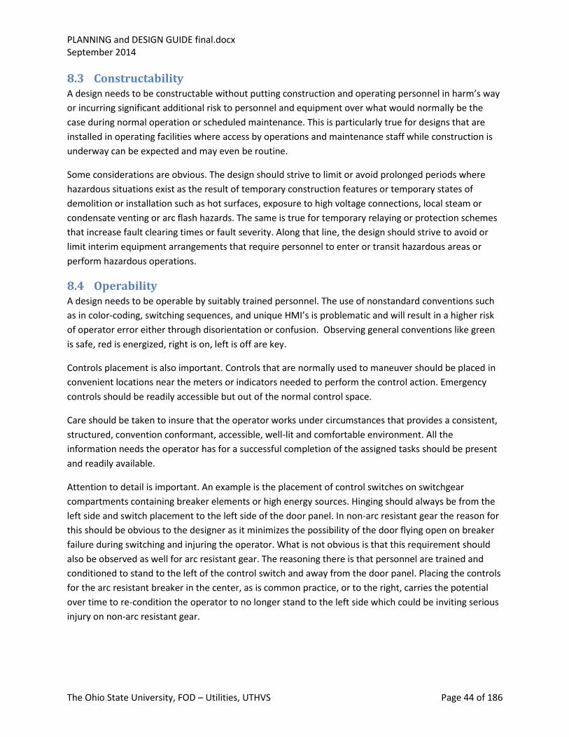
PLANNING and DESIGN GUIDE final.docx September 2014
The Ohio State University, FOD – Utilities, UTHVS Page 44 of 186
8.3 Constructability A design needs to be constructable without putting construction and operating personnel in harm’s way
or incurring significant additional risk to personnel and equipment over what would normally be the
case during normal operation or scheduled maintenance. This is particularly true for designs that are
installed in operating facilities where access by operations and maintenance staff while construction is
underway can be expected and may even be routine.
Some considerations are obvious. The design should strive to limit or avoid prolonged periods where
hazardous situations exist as the result of temporary construction features or temporary states of
demolition or installation such as hot surfaces, exposure to high voltage connections, local steam or
condensate venting or arc flash hazards. The same is true for temporary relaying or protection schemes
that increase fault clearing times or fault severity. Along that line, the design should strive to avoid or
limit interim equipment arrangements that require personnel to enter or transit hazardous areas or
perform hazardous operations.
8.4 Operability A design needs to be operable by suitably trained personnel. The use of nonstandard conventions such
as in color-coding, switching sequences, and unique HMI’s is problematic and will result in a higher risk
of operator error either through disorientation or confusion. Observing general conventions like green
is safe, red is energized, right is on, left is off are key.
Controls placement is also important. Controls that are normally used to maneuver should be placed in
convenient locations near the meters or indicators needed to perform the control action. Emergency
controls should be readily accessible but out of the normal control space.
Care should be taken to insure that the operator works under circumstances that provides a consistent,
structured, convention conformant, accessible, well-lit and comfortable environment. All the
information needs the operator has for a successful completion of the assigned tasks should be present
and readily available.
Attention to detail is important. An example is the placement of control switches on switchgear
compartments containing breaker elements or high energy sources. Hinging should always be from the
left side and switch placement to the left side of the door panel. In non-arc resistant gear the reason for
this should be obvious to the designer as it minimizes the possibility of the door flying open on breaker
failure during switching and injuring the operator. What is not obvious is that this requirement should
also be observed as well for arc resistant gear. The reasoning there is that personnel are trained and
conditioned to stand to the left of the control switch and away from the door panel. Placing the controls
for the arc resistant breaker in the center, as is common practice, or to the right, carries the potential
over time to re-condition the operator to no longer stand to the left side which could be inviting serious
injury on non-arc resistant gear.

PLANNING and DESIGN GUIDE final.docx September 2014
The Ohio State University, FOD – Utilities, UTHVS Page 45 of 186
8.5 Maintainability Maintenance provides a fertile field for safety considerations. Low hanging fruit are adequate lay down
space, a design that minimizes the need to work systems and equipment energized or pressurized,
adequate secure access in the design to points of repetitive maintenance, strategic placement of cranes,
hoists or other lifting devices.
Adherence to conventions also plays into a reduction in personnel error that can lead to injury or
equipment damage. Frequency of required maintenance is also an issue. The less maintenance required,
the fewer opportunities present themselves for accidents.
Equipment should be designed for ease of access, minimized risk of inadvertent contact with hot or
energized parts, and component layout that facilitates the removal and re-installation of components
without the need to disturb adjacent components, wiring or cabling.
Signage and labeling is important. Doing maintenance on the wrong equipment, particularly in
installations where there are multiples of the same equipment or components is all too common and
can be most effectively addressed by making sure that all systems and components are clearly, uniquely
and logically labeled and identified. Labels need to use the same nomenclature as the training aids,
drawings and hands-on procedures being used to support the maintenance activity. Labels are
important but they can be overdone. Avoid clutter. Quite often equipment is supplied with a host of
caution labels, many of which serve no practical purpose. A label advising “Unauthorized Persons to
Keep Out” on switchgear in an area with restricted access is worse than useless. It may actually distract
the operator from reading other notices and cautions needed for the safe operation of the equipment.
Bad labels
Top labels give useful information; Bottom Mfgr’s label is a distraction at best

PLANNING and DESIGN GUIDE final.docx September 2014
The Ohio State University, FOD – Utilities, UTHVS Page 46 of 186
Good label Mixed message Labeling minimal and task oriented
Clutter Labels Appropriate Labeling

PLANNING and DESIGN GUIDE final.docx September 2014
The Ohio State University, FOD – Utilities, UTHVS Page 47 of 186
Clear Labeling Unclear Labeling Caution useful, remainder is clutter
8.6 Reliability A design that achieves high reliability may require a high level of operator involvement, but usually
doesn’t. If it does, it is usually for routine adjustment of a fairly simple and repetitive nature. Most
systems, with any significant level of automation or frequency of duty cycle will need to operate at a
high level of reliability to avoid exposure to operator or maintenance error.
Note: the labels for the
buildings served: Blue for
normal feed, white or standby
feed.
This type of labeling helps the
operator execute the required
switching operations.

PLANNING and DESIGN GUIDE final.docx September 2014
The Ohio State University, FOD – Utilities, UTHVS Page 48 of 186
A good rule to live by in automation is KISS. Don’t make the controls any more complex than they need
to be. Added and unnecessary features tend to hide the required features and have an overall negative
impact on system operability and operator response. Paging through three or four levels of set points
and options to get to the one frequently needing adjustment is a really bad idea, particularly if the
features that have to be waded through were features designed to sell the system not get the job done.
If the activity is complex and the level of automation required is high, then you had better have reliable
equipment. If the equipment or system is touchy or unreliable, the control task had better be relatively
clear cut and simple with easily predicted and recognizable end results. It is important to recognize that
faulty or unpredictable automation invites operation with automatic features defeated by the operator.
There is little middle ground. Highly automated equipment that is unreliable poses a real challenge to
operators and maintenance personnel. Overly simplified controls requiring frequent fiddling are an
invitation to miss-operation. In the final balance human errors will significantly impact the overall
reliability outcome.
8.7 Safety and Risk Awareness/Avoidance Risk is all around us in an industrial environment. We employ a multifaceted, layered approach to limit
risk and promote safety. Our safety culture sets up barriers to risk and seeks to facilitate a prompt
reaction if a situation involving personnel safety should occur.
The first safety barrier is good design practice. It can reduce and remove certain elements of
risk.
The second barrier is training. It both increases the awareness of threats and provides an
effective means of negotiating known risks.
A third barrier is procedure. Adherence to procedure allows the worker to benefit from the
accumulated experience of others through the use of proven tools and methods for risk
avoidance and mitigation.
A forth barrier is physical in the form of labeling, signage, color coding, grounding, isolation and
lockage.
The last barrier is team work: the buddy system and pre-job briefings.
The first four barriers are related and depend heavily on having a solid, reliable, predictable, consistent
and well-thought-out and understood design. When designs are random, inconsistent and unnecessarily
diverse in equipment, conventions, operation and maintenance requirements, training, and
proceduralization: providing the soft barriers of training and proceduralization and establishing a viable
physical barrier are made much more difficult; their effectiveness more questionable.
The last barrier is pragmatic. No matter how many barriers to error exist, people still make mistakes and
accidents happen. Two of the most effective means of reducing errors and accidents are the pre-job
briefing and the use of the buddy system. The pre-job briefing facilitates previewing the planned work in
a team context and engages the workers in a thought process leading up to the actual work; sort of a
dress rehearsal. It is an opportunity to review procedures and share experiences and lessons learned.
The buddy system, where there are always two people present for any safety-critical activity insures

PLANNING and DESIGN GUIDE final.docx September 2014
The Ohio State University, FOD – Utilities, UTHVS Page 49 of 186
that two pairs of eyes will be on the work and two minds will be engaged. Should an activity result in an
injury, or a hazardous situation develop, there is a second person to take immediate remedial action.
And then there is Personal Protective Equipment (PPE). Knowing the hazard levels, having access to,
and using the appropriate level of PPE are the ultimate defense.
8.8 Design Margin One very effective way to reduce the need for PM and corrective maintenance is to design with a broad
design margin. Side benefits are usually extended service life, and in many cases, lower equipment and
system electrical losses as well.
Building margin into a design seldom happens automatically outside of code compliance. Manufacturers
and facility designers are paid to “value engineer” it out where permitted to do so. There is also the
issue of competitiveness. It is the owner operator who benefits from having substantial design
(operating) margins, not the manufacturer or the installation contractor, hence the need for the owner
operator to see that design and operating margins get into the specifications and stay there throughout
the value engineering phase.
An example of where a design margin can reduce personnel exposure to risk is in switchgear where
specifying design limits well above normal loading levels reduces or eliminates the risky job of doing in-
service thermal scans and the complicated and time consuming task of re-torquing bolted connections.
9 Detailed Design Criteria
9.1 Main Transformers
9.1.1 Introduction
The OSU Main Campus MV Distribution System is powered directly off AEP’s 138 kV transmission system
at two locations; OSU Substation and West Campus Substation. Each substation has three 3-winding
transformers that transform power from 138 kV down to 13.8 kV nominal for subsequent distribution
throughout campus. All six of these transformers are electrically similar and interchangeable. Two were
built in the late 1970s by Westinghouse and refurbished in 2013 by ABB. The remainder were built
between 2007 and 2012 by Delta Star. They were all manufactured with dual low-side extended range
load tap changers and no-load high-side tap changers. The two Westinghouse units are oil insulated; oil
cooled with two levels of forced cooling that utilizes both forced oil circulation and fan cooling. The
Delta Star transformers are oil insulated, oil cooled with two stages of forced air cooling but no oil
circulators. All six transformers are equipped with Nitrogen gas blanket systems and are continuously
monitored for dissolved gasses.
The transformers are rated at 75 MVA on a 55°C rise basis and 84 MVA on a 65°C rise basis. Individual
secondary windings are rated at half these values. Transformer BIL is 550 kV on the high winding and
110 kV on the secondary windings. The following illustration shows a typical large transformer
nameplate.
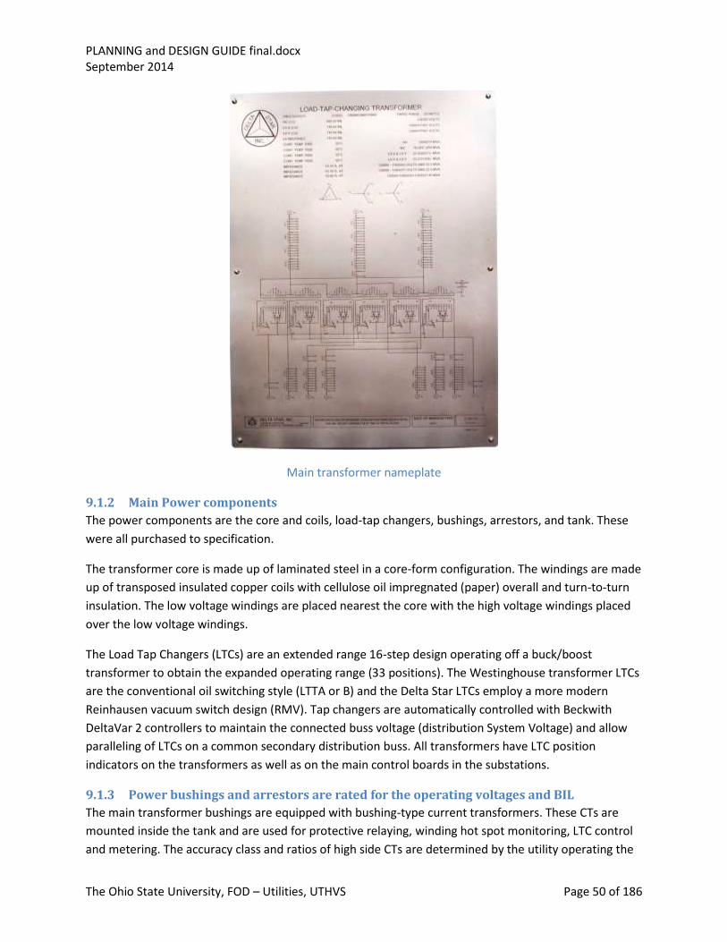
PLANNING and DESIGN GUIDE final.docx September 2014
The Ohio State University, FOD – Utilities, UTHVS Page 50 of 186
Main transformer nameplate
9.1.2 Main Power components
The power components are the core and coils, load-tap changers, bushings, arrestors, and tank. These
were all purchased to specification.
The transformer core is made up of laminated steel in a core-form configuration. The windings are made
up of transposed insulated copper coils with cellulose oil impregnated (paper) overall and turn-to-turn
insulation. The low voltage windings are placed nearest the core with the high voltage windings placed
over the low voltage windings.
The Load Tap Changers (LTCs) are an extended range 16-step design operating off a buck/boost
transformer to obtain the expanded operating range (33 positions). The Westinghouse transformer LTCs
are the conventional oil switching style (LTTA or B) and the Delta Star LTCs employ a more modern
Reinhausen vacuum switch design (RMV). Tap changers are automatically controlled with Beckwith
DeltaVar 2 controllers to maintain the connected buss voltage (distribution System Voltage) and allow
paralleling of LTCs on a common secondary distribution buss. All transformers have LTC position
indicators on the transformers as well as on the main control boards in the substations.
9.1.3 Power bushings and arrestors are rated for the operating voltages and BIL
The main transformer bushings are equipped with bushing-type current transformers. These CTs are
mounted inside the tank and are used for protective relaying, winding hot spot monitoring, LTC control
and metering. The accuracy class and ratios of high side CTs are determined by the utility operating the
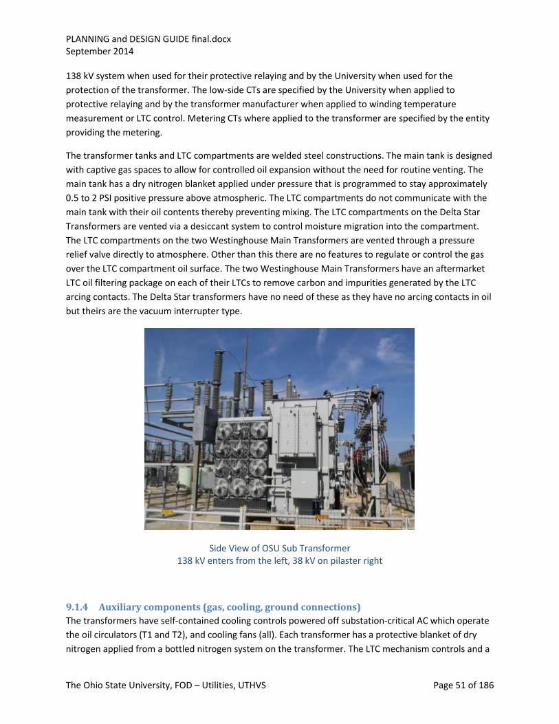
PLANNING and DESIGN GUIDE final.docx September 2014
The Ohio State University, FOD – Utilities, UTHVS Page 51 of 186
138 kV system when used for their protective relaying and by the University when used for the
protection of the transformer. The low-side CTs are specified by the University when applied to
protective relaying and by the transformer manufacturer when applied to winding temperature
measurement or LTC control. Metering CTs where applied to the transformer are specified by the entity
providing the metering.
The transformer tanks and LTC compartments are welded steel constructions. The main tank is designed
with captive gas spaces to allow for controlled oil expansion without the need for routine venting. The
main tank has a dry nitrogen blanket applied under pressure that is programmed to stay approximately
0.5 to 2 PSI positive pressure above atmospheric. The LTC compartments do not communicate with the
main tank with their oil contents thereby preventing mixing. The LTC compartments on the Delta Star
Transformers are vented via a desiccant system to control moisture migration into the compartment.
The LTC compartments on the two Westinghouse Main Transformers are vented through a pressure
relief valve directly to atmosphere. Other than this there are no features to regulate or control the gas
over the LTC compartment oil surface. The two Westinghouse Main Transformers have an aftermarket
LTC oil filtering package on each of their LTCs to remove carbon and impurities generated by the LTC
arcing contacts. The Delta Star transformers have no need of these as they have no arcing contacts in oil
but theirs are the vacuum interrupter type.
Side View of OSU Sub Transformer 138 kV enters from the left, 38 kV on pilaster right
9.1.4 Auxiliary components (gas, cooling, ground connections)
The transformers have self-contained cooling controls powered off substation-critical AC which operate
the oil circulators (T1 and T2), and cooling fans (all). Each transformer has a protective blanket of dry
nitrogen applied from a bottled nitrogen system on the transformer. The LTC mechanism controls and a

PLANNING and DESIGN GUIDE final.docx September 2014
The Ohio State University, FOD – Utilities, UTHVS Page 52 of 186
local cooling control station are on each transformer. The Beckwith automatic LTC controls are mounted
on the rear side panels main control board rears with the operator controls mounted on the panel
fronts.
Each transformer has an assemblage of meters and indicators which monitor top oil temperature,
winding temperature (hot spot), main tank and LTC tank levels, nitrogen blanket pressure and supply
tank pressure. The Delta Star transformer and LTC tanks have pressure reliefs which are instrumented
and alarmed. The main transformers are all factory-equipped with a sudden pressure relay intended to
detect rapid changes in transformer gas blanket pressure indicative of an internal transformer fault. The
design of the relay is such that gradual pressure rises typical of load changes or daily ambient
temperature changes will go undetected but a substantial and rapid pressure change will operate the
relay. These relays are sensitive devices mounted on the transformer main tank lids. Their output
contacts are a Form C configuration that will actuate while the pressure transient is occurring and then
reset after the event. The relay is usually applied in concert with a seal-in relay that converts the
momentary switch action to a sustained trip signal. In our application, we are following the AEP
standard and interfacing the relay through a GE HAA relay and using the relay and HAA contacts in series
to operate transformer lock-out relay. This configuration is chosen to reduce the likelihood of a
flashover of the relay contacts during a lightning or voltage transient event that would cause an
inadvertent trip of the transformer. In this version of the design the action of the relay and HAA are
momentary relying on the lockout relay to produce a sustained trip signal to the high side and secondary
transformer breakers. The following illustration shows a schematic for this application.

PLANNING and DESIGN GUIDE final.docx September 2014
The Ohio State University, FOD – Utilities, UTHVS Page 53 of 186
Sudden Pressure Trip Relay Schematic
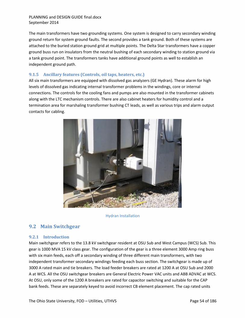
PLANNING and DESIGN GUIDE final.docx September 2014
The Ohio State University, FOD – Utilities, UTHVS Page 54 of 186
The main transformers have two grounding systems. One system is designed to carry secondary winding
ground return for system ground faults. The second provides a tank ground. Both of these systems are
attached to the buried station ground grid at multiple points. The Delta Star transformers have a copper
ground buss run on insulators from the neutral bushing of each secondary winding to station ground via
a tank ground point. The transformers tanks have additional ground points as well to establish an
independent ground path.
9.1.5 Ancillary features (Controls, oil taps, heaters, etc.)
All six main transformers are equipped with dissolved gas analyzers (GE Hydran). These alarm for high
levels of dissolved gas indicating internal transformer problems in the windings, core or internal
connections. The controls for the cooling fans and pumps are also mounted in the transformer cabinets
along with the LTC mechanism controls. There are also cabinet heaters for humidity control and a
termination area for marshaling transformer bushing CT leads, as well as various trips and alarm output
contacts for cabling.
Hydran Installation
9.2 Main Switchgear
9.2.1 Introduction
Main switchgear refers to the 13.8 kV switchgear resident at OSU Sub and West Campus (WCS) Sub. This
gear is 1000 MVA 15 kV class gear. The configuration of the gear is a three element 3000 Amp ring buss
with six main feeds, each off a secondary winding of three different main transformers, with two
independent transformer secondary windings feeding each buss section. The switchgear is made up of
3000 A rated main and tie breakers. The load feeder breakers are rated at 1200 A at OSU Sub and 2000
A at WCS. All the OSU switchgear breakers are General Electric Power VAC units and ABB ADVAC at WCS.
At OSU, only some of the 1200 A breakers are rated for capacitor switching and suitable for the CAP
bank feeds. These are separately keyed to avoid incorrect CB element placement. The cap rated units

PLANNING and DESIGN GUIDE final.docx September 2014
The Ohio State University, FOD – Utilities, UTHVS Page 55 of 186
can be placed into feeder positions and operated. The reverse is not true. At WCS all are 2000 A
elements are rated for capacitor bank switching and can be placed in cap and feeder compartments.
At OSU, the main busses power reactor limited feeder circuits as well as two satellite substations, one
near McCracken Power plant (Smith) and the other powering three busses at the South Campus Central
Chiller Plant. The feeders to Smith and the South Chiller plant are not reactor limited. West Campus
Substation has a similar buss configuration with provisions for two thermal/chiller plants as well. Both
substations have power factor correction CAP banks powered from each of their three main busses. As
presently configured, neither of the substations is equipped to provide internally generated net power
to the AEP system. We do parallel standby generation at Smith and at the chiller standby power facility
for routine load testing, however this generation is significantly smaller than the main campus internal
load so there is no net export interchange.
Overall One Line Diagram OSU/Smith/McCracken
Smith Substation has the same gear as OSU substation but arranged in a two high configuration. It too
has a three main buss design with each buss powering a number of reactor limited feeders. Smith also
powers the McCracken Plant via two sub-fed 13.2 kV busses powered independently from two of the
three Smith Sub feeds originating at OSU Sub. Refer to the station one lines for breaker ratings which
range from 2000 A down to 1200 A.
PLANNING and DESIGN GUIDE final.docx September 2014
The Ohio State University, FOD – Utilities, UTHVS Page 56 of 186
The South Campus Central Chiller Plant has three main 13.8 kV busses powered directly from OSU’s
three main busses via cables. The main switchgear at that facility is Powell Powlvac gear, a version of
Cutler Hammer (Eaton) MV metal enclosed switchgear. It carries the same basic ratings as the OSU gear.
Refer to the station one line for specific ratings of switchgear components.
9.2.2 Base rating
The base rating of the main switchgear at OSU and WCS is 1000 MVA, 3000 A. This refers to the main
feeders and tie breakers as well as the buss itself. While the main feeders are rated at 3000 A, the
transformer secondary’s supplying them have a full-load forced cooled rating of just under 1800 A and
can be loaded on a short-term emergency level of 2400 A (one hour limit). The secondary windings have
individually stick-operated disconnect switches that are rated 2000 A. This is an AEP rating applied to a
switch design that has a manufacturer’s rating of 3000 A. The individual main busses are rated at 3000
A. At OSU, the maximum load they are capable of supporting can be well in excess of 3000 A, as the OSU
main feeds attach to the buss sections at extreme opposite ends, with loads distributed end-to-end. This
observation is only true for the OSU Sub. At WCS the individual busses are fed from one end. In actual
practice, loading a buss in excess of the 3000 A rating should be avoided as it places limits on the
operation of tie breakers during maintenance or emergency situations.
Main and tie CBs are interchangeable and keyed to only go into 3000 A positions. 2000 A CBs at WCS
Substation are of one design and interchangeable. They are keyed to go into any street circuit feeder or
CAP Bank position. At OSU, the 1200 A CBs are in two versions; standard and capacitor rated. These are
keyed accordingly, with cap rated keyed for the CAP bank positions and the general design keyed to go
into the street circuit feeder and spare positions. Since the initial installation at OSU sub, all replacement
and new 1200 A CBs have been purchased as cap rated. Cap rated CBs can be placed in CAP bank and
feeder positions in the switchgear.
9.2.3 Construction
The main switchgear at OSU and WCS is fully-rated, metal-enclosed gear. Controls are at 125 VDC. Main
and tie breakers are equipped with dual trip coils. The switchgear assembly is one high with the top
compartments housing metering and protective relays, CB controls and fusing.
The main switchgear at OSU is not arc resistant gear. All mains and tie breakers (with the exception of
CB 315 buss 200-300 tie) are in the south line-up along with buss 100 feeder breakers. Buss 200 and 300
feeder breakers, with the exception of the feeds to Smith Sub (CB 210 and CB 310) along with CB 315
are in the north line-up. Interconnections between the north and south buss line-ups are by cable in tray
and rated at 3000 A.
The main switchgear at WCS is arc resistant gear. All the switchgear is in one area of a large
prefabricated equipment enclosure. Access to the front of the gear is from the enclosure. Access to the
rear is through exterior enclosure access doors into the rear panels of the switchgear. Arc venting is to
the exterior of the enclosure via ducting that connects the arc flash plenums over the gear to louvered
vent panels on the exterior of the enclosure. The busses and feeder CBs are arranged along the south
side of the enclosure. The main feeders and buss tie breakers (Main-Tie-Main) are spotted along the

PLANNING and DESIGN GUIDE final.docx September 2014
The Ohio State University, FOD – Utilities, UTHVS Page 57 of 186
north wall of the enclosure with station service and control panels interspersed at intervals. Connections
between these Main-Tie-Main line ups and the main buss sections is made with non-segregated 15 kV
3000 A enclosed buss duct run between sections of switchgear, under the enclosure and up into
transition positions on the west ends of the switchgear and both sides of the Main-Tie-Main line-ups.
Main-Tie-Main at WCS
9.2.4 Arrangements
The basic design is a ring buss. This arrangement allows flexibility to power the busses in a variety of
configurations that support transformer and feeder maintenance and at the same time helps
accommodate the extended loss of one or more main transformers in a substation. Since the individual
busses are the focal point for voltage regulation (via main transformer secondary winding LTCs) as well
as power factor correction, they are the points where system voltage is regulated. Potential
transformer compartments located in the main buss line-up house the potential transformers that
provide voltage feedback to the LTCs as well as supply signal voltage to the buss and feeder metering.
At OSU sub, the buss line-ups also contain station service transformer compartments. These are no
longer in service.
9.2.5 Features
Metering throughout the main substations is via ION meter units (Square D Snyder). These individual
cubical mounted meters are used for local display of feeder current, voltage and loading. They also feed
data into a central data acquisition system used to track and log system loadings, power quality and
system transients.
Switchgear controls and protection is based on a 125 VDC battery system designed to provide critical
control and protection power for a period in excess of eight hours after the complete loss of Station AC.

PLANNING and DESIGN GUIDE final.docx September 2014
The Ohio State University, FOD – Utilities, UTHVS Page 58 of 186
Our preference is to have the switchgear breakers and cubicles designed to facilitate closed-door racking
and removal of the breaker elements for test and for LOTO without the need for a trolley, ramp or
racking lift. The design of the arc resistant gear at WCS and the chiller plants and the two high design at
Smith necessitate the use of a trolley to insert and remove circuit breaker elements.
Switchgear protection is provided with test switches to facilitate relay calibration and testing. The
protective relays at OSU substation are a mixture of Siemens Siprotec Relays and SEL relays, with only
SEL relays used for Main Transformer protection functions and the Siemens relays applied to most
feeder protection. At WCS all relays are SEL.
Feeder protection and control is mounted in the metering compartments over the individual breaker
cubicles. Transformer protection is located away from the switchgear and on the main control panels.
Street Feeder Switchgear Panel—front view
Grounding provisions are in the rear to ground the terminations for incoming cables. These provisions
are for ball studs and a cabinet ground buss extension into the rear compartment in the area of the
cable terminations and readily accessible. Grounding studs on live terminations need to be insulated.
The preferred way is to fit an insulating cap that can be easily removed with a suitable tool.
9.2.6 Labeling
All switchgear cubicles and switchgear mounted devices on the front and rear including the cubicles are
labeled. In addition all load feeder cubicles are fitted out with magnetically-backed labels listing
PLANNING and DESIGN GUIDE final.docx September 2014
The Ohio State University, FOD – Utilities, UTHVS Page 59 of 186
individual buildings fed off the Feeder. These labels come in two versions: black on blue for normal feed
alignment and blue on white for alternative feeder alignment. As building normal assignments may
change, the magnetic backing allows them to be moved to the appropriate cubical location.
Permanent labels are placed on the panel fronts to provide instructions and cautionary information
(Yellow). Red caution tape labels are permanently attached to the cubical rears to warn of potentially
hazardous situations or traps that could arise from back feeds, operator disorientation or
misinterpretations.
9.3 Standby Generation Paralleling Gear
9.3.1 Introduction
On Site generation may take on a variety of forms.
The most common is emergency generation. This form is usually located at individual facilities or
grouped for a number of facilities, generate at low voltages (600 V or less), and have a starting
requirement of ten seconds or less. This form of generation typically feeds its loads through a transfer
switch which allows the loads to be switched between the generation and the normal (utility) source of
power in an open transfer scheme. In almost all cases there is no need of paralleling gear. BRT is an
exception where there are multiple critical emergency load busses and more than one emergency
generator.
The least common is co-generation. Co-generation is generation that is designed to operate in parallel
with the normal or utility source. This may take a variety of forms ranging from the conventional engine
generator version to wind generation, solar or fuel cell technology where the power output is into the
existing distribution system but via static converters. The engine generator or rotating AC generating
systems require paralleling gear. The static-based generation usually has built into it the capacity to
convert direct current into phase-controlled alternating current at power system frequency. Such
systems generally do not require paralleling gear but only a disconnect means.
Standby generation, while less common than emergency generation, is nonetheless prevalent where a
substantial source of AC power is required for a sustained period of time to support substantially more
electrical load than would be required of an emergency power system. Starting times in the order of ten
seconds to sixty seconds are common, though some may take appreciably longer to start and load
because of the prime mover technology applied; gas turbines being among the slowest. It is not always
practical to group all loads requiring standby power onto a separate buss; therefore it is common for
standby generation to supply power directly to the facility power system at elevated voltage (5 kV or
13.2 kV). Also the size of the units usually makes it impractical to apply load banks for routing
surveillance testing. Paralleling standby power generation to the utility for testing and re-transfer after
normal power restoration is common practice. Where testing by paralleling the utility involves more risk
of damage to the engine generator set and is not as all inclusive and thorough, it has the advantage of
requiring less load switching and allows for a much simpler buss arrangement. Paralleling gear is needed
in this case to allow for paralleling the utility as well as paralleling individual generators to each other for
more effective load assumption and source redundancy.

PLANNING and DESIGN GUIDE final.docx September 2014
The Ohio State University, FOD – Utilities, UTHVS Page 60 of 186
SCCCP Paralleling Gear SCCCP Paralleling Gear (left); Woodward EasyGen HMI (right)
9.3.2 Modes of Operation
Unlike emergency generation which is required to operate in a mode where it sets the frequency and
voltage levels, Standby generation must operate in this mode (islanded) and in parallel with the Utility as
well. When operating in parallel with the utility, it is the utility that establishes the system frequency
and voltage. The standby generator governor and excitation equipment must be designed to recognize
when it is in one or the other of these operating modes and make internal adjustments accordingly for
stable operation. Since standby power systems tend to be larger and involve multiple generating units,
there need to be provisions for multiple units to share load and reactive current as well.
Also unlike emergency power generation, standby power generation commonly does not start directly
on loss of critical buss voltage. Because it often generates directly into facility distribution systems, it
needs to be designed to ignore some system outage conditions that would be otherwise be remedied by
buss transfers or manual switching to alternative buss feeds. There will also likely be a concern for
overloading and a need to do some form of selective load shedding. The two standby systems in service
on campus use a logic that establishes total loss of utility before initiating a load shedding and diesel
starting process.
9.3.3 Design Features
9.3.3.1 Generator and excitation design
Standby power system generator sizing at face value would appear to be the direct result of the prime
mover sizing. There are cases however where the sizing of the generator can be independent of the
prime mover and based on the starting requirements of the larger system loads.
Load power requirements determine the power rating of the MG set as they set the engine HP, inertia
(Flywheel or WR^2) and governor performance requirements. Motor starting current which can
approach as much as six times the rated running current is at low power factor and places a

PLANNING and DESIGN GUIDE final.docx September 2014
The Ohio State University, FOD – Utilities, UTHVS Page 61 of 186
disproportional burden on the generator to supply reactive current and sustain adequate buss voltage
so as not to stall loads that are already running.
A commonly used approach to sizing MG sets is to assume the MG set is operating with an almost fully
loaded buss and then start the single largest load last. The acceptance criterion for the prime mover and
governor is system frequency. The acceptance criterion for the generator and excitation system is
system voltage. In situations where the largest motor is a small percentage (20% or less) of the
generator rating, the generator rating can match the prime mover with a nominal output power factor
(0.8 to 0.9 range). In instances where the motor is large (25% of the prime mover or greater), it may be
necessary to oversize the generator. This affords greater reactive capacity, adds to the WR^2 and a
lower transient impedance as well.
9.3.3.2 Engine sizing
Prime mover sizing is based on the total anticipated load and the largest anticipated block load. The
manufacturer will usually provide a recommended maximum step loading on starting and running.
Modern electronic engine control systems offer a vast improvement over the older conventional
mechanical governors, and assuming load changes up to 50% of the prime mover rating is common. If
there is any question on motor starting performance the vendor should be requested to model the
anticipated loading cycle. For a loading cycle that involves a nominal block load and manually initiated
load additions, this may reduce to modeling the largest load to be added at the end of a loading
sequence. For applications where load sequencing is automatic, a full simulation should be performed to
establish minimum load addition intervals.
9.3.3.3 Paralleling Buss configuration
Paralleling buss configuration is dependent on the application. In the simplest form it may be a
generator breaker and a utility supply breaker in an existing buss line-up. In this case the standby MG set
is started and once voltage and speed set-points are met, the generator breaker will be signaled closed.
If the load buss is de-energized (dead buss assumption) only MG set voltage and frequency set-points
need be met. If the buss is energized as would be the case when paralleling to the utility for a
surveillance loading test, then synchronizing is required to match utility frequency, phase angle and
voltage. In the dead buss assumption situation, it is also necessary to interlock the generator breaker
controls to the utility source breaker to insure that the utility source is open before the generator
breaker closes to avoid the possibility that the generator will close into and back feed the utility and its
unshed load. In the case where there is more than one standby generator, only the first to close on the
load buss will use the dead buss assumption, the remainder will go through a full synchronizing
sequence. The synchronizing equipment must be designed to insure that no two generators will attempt
to do a dead buss assumption or parallel at the same time. It is also standard practice to apply a check
sync relay to supervise the breaker closing and make sure that the closing signal falls within a safe slip
frequency and relative phase angle window.
A common and slightly more complex version is where the paralleling gear is separate from the load
buss and, on loss of utility, the standby power system is signaled to start the standby generation and
assume the load buss. This configuration is common where there is more than one source of standby

PLANNING and DESIGN GUIDE final.docx September 2014
The Ohio State University, FOD – Utilities, UTHVS Page 62 of 186
generation to be paralleled to manage the load. In that case the paralleling gear is made up of the
generator breaker(s), a utility breaker, and may involve a tap to supply generator auxiliary loads directly
off the paralleling gear main buss.
The main buss in the paralleling gear may be operated normally energized from the utility or be
energized only when the standby generators are running. Normal power system configuration and
provisions for routine periodic standby power system load testing usually weigh into this design
decision. The paralleling/synchronizing process is the same.
Synchronizing
AC power is characterized by its voltage, frequency and phase angle. Polyphase (3 phase) AC Power also
is characterized by its phase rotation. Paralleling AC systems has to take all of these into account. When
paralleling two AC power sources which share a common source, as would be the case in a double-
ended substation when both secondary mains are closed and the tie is being closed, frequency and
phase angle are not an issue as the busses on both sides of the tie are matched. Likewise, unless the
taps on both source transformers are set differently, voltage, barring buss loading effects, will also be a
virtual match. Parallel between two or more generators, or generators and a utility-supplied source is
another thing entirely. In this case each source has its own voltage, frequency and rotation. Even if the
frequencies are matched they may not be in phase or not have the same rotation.
Utility sources are made up of many different generating sources and are very good at holding system
frequency constant; so much so that people have for a long time set clocks by them. Utilities actually
dispatch their generation to correct for an integrated time error over the course of the day so as to keep
customer clocks on time.
Individual generation sources are relatively small by comparison, even when generators are grouped
into an islanded system as happens or has been the case in the past in Texas and parts of Florida.
Paralleling between systems or paralleling an individual generator to a small system or a large Utility
grid is a lot more complicated than closing a tie breaker.
In the short version, paralleling is the same basic process regardless of whether you are paralleling two
generators, a generator and a utility, or a multi-generator system to a utility. It is done as follows:
Pick a reference source from the sources to be paralleled; usually the larger and most stable
system for your “running buss”
Adjust the frequency (speed) and voltage of the source to be paralleled (“starting buss”) to the
running buss so as to come close to matching source frequencies. Preferred practice is to have
the starting buss run a bit faster than the running buss (tends to avoid motoring problems post-
parallel). Monitor the relative phase angle between the starting and running busses. When the
frequencies are relatively close the relative phase angle will slowly sweep through 0 Deg. to 180
Deg and back to 0 Deg. again. The paralleling breaker should be signaled to close a few degrees
ahead of 0 degrees to allow time for breaker closure. That’s all there is to it except for the
practical details.

PLANNING and DESIGN GUIDE final.docx September 2014
The Ohio State University, FOD – Utilities, UTHVS Page 63 of 186
This whole process can be done manually if the necessary information is available to an operator. To do
it manually you need to read running and starting buss voltages. You need to have manual control over
the starting buss voltage (generator output voltage). You need to be able to read or sense speed or
frequency. You also need to have a means of adjusting the start buss frequency (generator speed). You
need to be able to read relative phase angles of the start and run busses. You need to have a display
showing in-phase or relative phase angle difference, and you need to have a control switch or equivalent
to signal when the two systems are in phase. All this, and an operator and you can parallel. Take out the
operator and add a relay with all the powers of the person to monitor and adjust speed, voltage and
signal a circuit breaker to close and you can do it automatically. Staying paralleled and stable is another
story but for now we can concentrate on paralleling.
All the information mentioned above needs to be reliable and properly connected. The running and
starting busses must have the same phase rotation. The voltage measurements must be connected to
the same phases and/or be in phase when the paralleling breaker is closed. In addition to being in-
phase, the voltages need to be close in nominal value to facilitate matching.
The paralleling breaker need not be a generator breaker. Often the generator breakers are the
paralleling points on a standby or emergency power system to get all generating elements initially
connected, but when the time comes to re-connect to the utility; that will be done at a different point
on the system.
Regardless the process is the same as outlined above. The same run buss/start buss approach is used
with the run buss being the utility buss and the start buss being the system whose voltage and
frequency can be controlled locally. Here, as before, the choice of monitoring points for synchronizing
potential is key. The choice of paralleling point is an operating decision and dependent on buss
arrangement at the time the operator wishes to re-establish a connection to the utility. All that is
needed to accommodate this is to have the paralleling (synchronizing ) controls designed to that an
appropriate start and run buss can be selected and the start buss generation controlled for voltage and
frequency.

PLANNING and DESIGN GUIDE final.docx September 2014
The Ohio State University, FOD – Utilities, UTHVS Page 64 of 186
Smith Sub DG Paralleling/Sync Panel
Any synchronizing system is subject to failure. Manually synchronization is subject to equipment and
human error. Automatic synchronizing is subject to equipment failure. Most synchronizing equipment
will recognize the presence of sensed voltage as a prerequisite to synchronizing. This is to provide some
protection against a blown fuse in the run buss synchronizing potential source. The first generator to
parallel to a buss in a blackout scenario will be assuming a dead buss, however. Synchronizers usually
are equipped with an external input to enable dead buss assumption which can be used to enable the
synchronizer to parallel the generator to an initially dead buss when that scenario is anticipated. The
second generator to parallel in a multiple generator system will go through the full synchronizing
scheme. A common measure to avoid inadvertent out-of-phase paralleling is to apply a “check sync”
relay to supervise the synchronizer (automatic or human). This device has a phase-angle window and
time delay that insures that the relative phase angles are reasonably close for a reasonable period of
time before it will allow a sync close pulse from the synchronizer to close the paralleling breaker. This
accommodates two objectives; making sure the angles are reasonably close and blocking a close pulse
when the angles are close but the frequencies are not closely matched and the close delay of the
breaker might result in excessive out of phase closure. Sync check relays are also applied even in the
absence of a synchronizer where inadvertent out-of-phase breaker closure is a possibility.
While synchronizing equipment can cover a wide range of hardware designs, there are some basic
configurations and building blocks common to all. With the advent of microprocessor digital controls
designs have migrated to an “all the works in one box” approach with startup, synchronizing, loading
and mode selection all being done by the same instrument. The box, in essence, is an aggregation of all
the elements mentioned above needed to accomplish paralleling.
First there is a synchronizing relay function. When turned on its purpose is to adjust the operation of the
Starting source to match frequency and voltage to the running source. Once this is accomplished, its

PLANNING and DESIGN GUIDE final.docx September 2014
The Ohio State University, FOD – Utilities, UTHVS Page 65 of 186
purpose shifts to one of making sure that the paralleling breaker closes at the correct time under
acceptable conditions. To do this it must be able to sense and compare frequency of the run and start
busses, and produce increase or decrease signals to the start source prime mover(s). It must also be able
to sense and compare run and start buss voltages and produce increase or decrease signals to the
starting source excitation controls. Other features include a jog signal for situations where speeds are so
well matched that the phase relative phase angle fails to go through zero deg. In a reasonable amount of
time, a feature that requires the relative angle to go through zero once or more before the close pulse is
generated and an incomplete sequence time-out to block further synchronizing activity.
Next there is a method of selection for choosing the appropriate start and run busses, since there may
be a range of paralleling options. There is also likely to be a sync check feature. This can be part of the
paralleling controls and shared across combinations of starting and running busses or can be resident in
the paralleling breakers control circuits. If paralleling to a utility or “stiff” source is one of the paralleling
options, there must also be a logic determination as to whether the starting source loading
characteristics will be based on a speed control regimen or a load control regimen. The same is true for
the excitation controls which would be in voltage regulation mode if islanded or power factor mode if
paralleled to a utility source. In a simple component-based paralleling control design these are the basic
components.
When manually synchronizing, a specialized device called a synchroscope is usually applied. It has the
presentation of a clock face with a pointer that rotates 360 Deg. Showing the relative phase angle of the
start and run buss. Not all designs use a synchroscope though, as light bulbs wired between the
synchronizing potentials of the run and start busses can serve the same purpose as well. The brightness
of the bulb serves to show how out-of-phase the source voltages are (bright: way out, off: in-phase).
Some application use clear bulbs with special filaments to make viewing small voltage differences more
practical. To guard against inadvertent false signals from a filament failure, more than one bulb may be
used.
The “all the works in one box” version may contain a lot more functionality and include automatic
startup, paralleling, loading and testing modes, unloading and equipment pre-load and shutdown
requirements such as initial minimum load assumption and cool down (run out).
EasyGen DG HMI on SCCCP DG Generator Control Panels

PLANNING and DESIGN GUIDE final.docx September 2014
The Ohio State University, FOD – Utilities, UTHVS Page 66 of 186
Regardless of the approach taken, synchronizing is a process with a need for a defined situation and
objective, a sequence to be followed, an endpoint to be achieved and a determination that the process
has been successful; which infers it will go to reset or a lock-out condition depending on the outcome of
the synchronizing attempt. Having a synchronizing system armed and poised to parallel but incomplete
is analogous to having a fire arm loaded, cocked and pointed without a target; definitely a situation to
be avoided.
9.3.3.4 Load Shedding and Sequencing
Standby Power systems may not be sized to assume the total normal system load and even if they are,
the limited loading capacity of the MG set may not be able to assume the full transient loading. For this
reason it may be necessary to provide controls to shed buss loads and then start loads in groups, or
individually to a loading schedule chosen to stay within the transient and steady state loading limitations
of the MG sets. The exception is where the initial loss of power or the initiation of the standby power
results in shutdown and no automatic restarting of buss loads on buss voltage restoration. Load
shedding and sequencing controls can be via relay logic or done in the process control automation. If
performed by relay logic, care should be taken to observe the design practices noted in the Relay Logic
section of the manual with particular attention to the avoidance of fail-safe designs and the use of
lockout relays. If performed by the process control automation, care should be taken to guard against
spurious initiation of the load shed feature.
9.3.3.5 Governor and Excitation Control
Because Governors and excitation control (voltage regulators) have to function in an islanded mode and
paralleled to the utility, they tend to be a bit more complex.
Governors operating in an islanded mode can be set to a relatively high gain. Installations with more
than one generator require the inclusion of a load-sharing module or the digital control equivalent
function in the governor system. These features allow them to share load and at the same time regulate
system frequency to within very tight limits which in turn helps in keeping process system flows and
pressures balanced. When operating paralleled to the utility, high gains result in unstable operation.
Gains have to be lowered in a conventional speed (frequency) governor to get stable operation.
An alternative and more useful approach is to apply a load rather that speed governor function. In this
type of governor, the EG set output power is selected regardless of system frequency. This would not
work in an islanded mode as the load is frequency dependent and finite. Too high a load setting would
over frequency the system, too low would reduce system frequency and create electrical and
mechanical system problems.
When a standby power system has to operate islanded and be paralleled to the utility (periodic testing
and restoration) as is usually the case, a governor that can combine these two functions, speed and
load, is needed, as well as a way of determining the operating status of the system (islanded or
paralleled).
The situation with excitation control is analogous.

PLANNING and DESIGN GUIDE final.docx September 2014
The Ohio State University, FOD – Utilities, UTHVS Page 67 of 186
When operating islanded, the generator excitation controls buss voltage. If there is more than one
generator on the buss, their voltage regulators need to be set up to share reactive. This can be done
either by providing a form of cross-current compensation to split the reactive loading or setting up the
voltage regulator’s compensation circuits to each regulate a point internal to its generator. Of the two
alternatives, the cross-current version is superior as it provides more precise buss voltage control.
Compensation set to regulate a point internal to the generators will split reactive but also produce some
undesirable voltage droop or swell on the load buss.
When operating in parallel with the utility, the voltage regulator operation needs to change from
voltage control to power factor control. Reactive balancing is less of an issue as the reactive loading of
each generator is set by its own regulator and is programmed by the generator power level.
It is important to note that with alternating current MG sets the governor determines MG set loading
not the excitation. The only effect on load when paralleled to the utility is changes in electrical losses
which is a minor element of the power picture. The major effect is reactive current changes. When
islanded, changing the terminal voltage will increase buss voltage somewhat and voltage sensitive loads
will increase in load. Motors and self-regulating loads such as temperature controlled heaters will see
little or no change and may even, as in the case of motors, decrease load slightly depending upon their
initial operating point.
9.3.3.6 Generator Loading
As mentioned earlier, alternating current MG set loading is done by adjusting the governor while in
parallel with the utility. Loading is done manually or run up to a set load point by the engine control
system to a predetermined program in some cases, but a minimum load to avoid motoring in almost all
cases. Loading is automatic when islanded and the governor is operating as a speed governor. There is a
speed load curve for most frequency-sensitive loads such as pumps. The MG set governor will sense
speed or frequency and utilizing a droop characteristic will increase or decrease prime mover power to
maintain the MG set speed. The intersection of the governor’s droop characteristic and the load’s speed
load curve will determine the system operating frequency. The governor may also contain an integral
plus reset function to cancel out the droop effect and eventually return to the desired nominal system
frequency.
9.3.3.7 Engine Generator Testing
Testing involves two different testing routines.
The first is functional testing. This generally involves a setup of the standby power system to react to a
full or partial utility loss and recover to the point where load can be returned to the normal utility
connection. This testing is performed periodically, typically on an annual basis and can get quite
involved. Scheduling such a test usually requires that the test be conducted at moderate to low facility
demand to limit process and disruption. If the standby power system is designed to power only part of
the plant load, then the functional testing needs to include testing not only the MG sets but also the
load shedding and load sequencing as well.

PLANNING and DESIGN GUIDE final.docx September 2014
The Ohio State University, FOD – Utilities, UTHVS Page 68 of 186
Routing surveillance testing is a simpler routine, normally conducted monthly and involves starting the
MG set, paralleling it to the utility supplied buss and loading it to between 75 and 100% load. It is
designed to demonstrate that the EG set is capable of running and loading and that the auxiliaries are
fully functional.
If a load bank is available for routing testing, it may be substituted for buss load, the utility connection
and allow the test to exercise more of the MG set design features. It is a more realistic test for the
governor and fuel side of the set but does nothing additional to exercise the excitation for transient
loading similar to what would be experienced under actual operating conditions. Adding a reactive
component to the load bank to obtain loading power factor adds more realism but still falls short of
simulating loading effects like transformer inrush or motor starting current transients. The load bank
approach is generally employed to minimize the time the MG set is paralleled to the utility source. Many
applications prefer this to loading in parallel with the utility because it minimizes the risk of damage
from internal MG set failures and from utility power system upsets. An MG set surveillance test can be
run unattended when on load bank but should be continuously monitored when on utility.
9.3.3.8 Relaying and Grounding
Standby generation relay protection has some unique features not present in emergency generation
protection and not present in the normal MV plant and substation distribution relaying.
Standby generation is a limited fault source for most applications which requires the relay protection
system to deal effectively with both high current and relatively low current fault levels. Phase faults are
limited by the transient and synchronous reactance of the generator. Some excitation systems are
actually designed with fault support built into the voltage regulators to achieve relayable levels of fault
contribution. In many cases, the distribution system inherent relay selectivity and coordination will not
work when on standby generation either because of the location on the system of the generator
connection or because the fault support is too low and the distribution system protectives are operating
in an overload range vs. their fault range.
This is even more of a concern for ground faults. Generator grounding is high impedance to limit the
damage likely from an internal generator winding or bushing ground fault (200 A or less). This leaves
little room for downstream coordination. Quite often it is necessary to live with a single zone of ground
fault protection and trip the entire system for a ground fault regardless of location.
Multiple generators on a common standby-buss present additional issues. Since they all will contribute
to a ground fault, having multiple generators means that an internal fault in one will see a contribution
from all. To avoid this it is common to form a shared generator neutral buss and bring it to ground
through a common resistor. With this configuration, isolating the fault to the system or one of the
generators increases the level of complexity of the ground fault relaying needed and frequently results
in a decision to abandon selectivity and trip off all generation for a ground fault.
The fact that the generators are active devices introduces a set of operational concerns that require
specialized relaying. Common relay functions, i.e. loss of excitation, over excitation (volts per Hz),
differential current, phase unbalance (negative phase sequence), loss of synchronism (pole slippage),

PLANNING and DESIGN GUIDE final.docx September 2014
The Ohio State University, FOD – Utilities, UTHVS Page 69 of 186
field ground, field forcing, reverse power, high vibration and high stator temperature. Voltage restrained
phase overcurrent relaying are used to strike a balance between the need to protect the generator from
overload and the need to obtain some level of selectivity in fault clearing. Another consideration is for
inadvertent generator breaker closing with the MG set at standstill which could damage both the
generator and the prime mover. In addition to the relaying which is applied to shut down and in most
cases lock out the generator, the governor and excitation systems typically have their own trips and
limiters designed to protect the MG set.
Auxiliary Features
Standby Power systems, because they have to startup and operate independent of normally available
services, generally have their own set of auxiliary equipment. Among these are a fuel delivery system,
building ventilation and engine cooling system, starting system and supervisory.
There are several aspects to fuel delivery that need to be accounted for in the design. One is onsite
short term storage for the initial system starting and operation prior to assuming load and re-
establishing the normal delivery system with access to the main fuel storage facility. This is particularly
true for diesel generation where the main fuel oil supply is likely to be remote from the generation and
need a delivery system. Temporary local storage commonly involves the use of a day tank either
separate from the engine or in some cases actually part of the engine skid. It is sized to provide for only
limited running time. The sizing of the tank has to provide adequate fuel for the maximum time
anticipated to power up and align to the larger centralized storage and appropriately sized to support a
reasonable refilling cycle from this remote system. Tank capacity us usually in terms of an hour or more
DG running time at full load, though it may be longer or shorted depending on design requirements or
regulatory commitments. Day tank systems usually depend on gravity to insure oil supply and engine
driven pumping to return unused fuel oil to the day tank.
Smith Standby DG Day Tanks
Cooling systems may be powered mechanically directly off the motor or standalone systems with fans
and circulators. The direct connected type of cooling that relies on the engine for power avoids the
availability issue but has to be physically on the MG set which involves opening the DG area to exterior
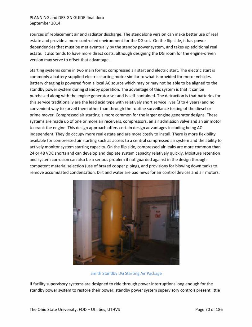
PLANNING and DESIGN GUIDE final.docx September 2014
The Ohio State University, FOD – Utilities, UTHVS Page 70 of 186
sources of replacement air and radiator discharge. The standalone version can make better use of real
estate and provide a more controlled environment for the DG set. On the flip side, it has power
dependencies that must be met eventually by the standby power system, and takes up additional real
estate. It also tends to have more direct costs, although designing the DG room for the engine-driven
version may serve to offset that advantage.
Starting systems come in two main forms: compressed air start and electric start. The electric start is
commonly a battery-supplied electric starting motor similar to what is provided for motor vehicles.
Battery charging is powered from a local AC source which may or may not be able to be aligned to the
standby power system during standby operation. The advantage of this system is that it can be
purchased along with the engine generator set and is self-contained. The detraction is that batteries for
this service traditionally are the lead acid type with relatively short service lives (3 to 4 years) and no
convenient way to surveil them other than through the routine surveillance testing of the diesel or
prime mover. Compressed air starting is more common for the larger engine generator designs. These
systems are made up of one or more air receivers, compressors, an air admission valve and an air motor
to crank the engine. This design approach offers certain design advantages including being AC
independent. They do occupy more real estate and are more costly to install. There is more flexibility
available for compressed air starting such as access to a central compressed air system and the ability to
actively monitor system starting capacity. On the flip side, compressed air leaks are more common than
24 or 48 VDC shorts and can develop and deplete system capacity relatively quickly. Moisture retention
and system corrosion can also be a serious problem if not guarded against in the design through
competent material selection (use of brazed copper piping), and provisions for blowing down tanks to
remove accumulated condensation. Dirt and water are bad news for air control devices and air motors.
Smith Standby DG Starting Air Package
If facility supervisory systems are designed to ride through power interruptions long enough for the
standby power system to restore their power, standby power system supervisory controls present little

PLANNING and DESIGN GUIDE final.docx September 2014
The Ohio State University, FOD – Utilities, UTHVS Page 71 of 186
challenge and may be integrated into the normal facility supervisory. If not, special attention needs to
be paid to powering the standby power system supervisory during and after power interruption.
Surveillance systems need to be able to control and monitor the standby power system availability,
starting, operation, loading and shutdown. This includes both local and remote locations where the
need for operator intervention is anticipated. Supervisory systems designed to be active only during
standby power system operation need to have their surveillance testing included in the standby power
system surveillance program to insure their readiness for service.
9.3.3.9 Surge Protection
Generators are susceptible to voltage surges. Surges can be generated by switching transients and from
environmental effects such as lightning. The standard surge protection package for a generator involves
adding surge capacitors and lightning arrestors close to the generator terminals. The lightning arrestors
clamp the surge voltage and the capacitors shape the transient voltage to reduce the generator stator
turn to turn voltage caused by the transient wave front. Most AEs will apply this package to any
generator without analysis. In reality it is required only if the MG set is likely to be exposed to transients.
These packages should not be applied where they are not needed because of the risk for failure or miss-
operation. Installations requiring such protection are applications where the generators are directly
exposed to distribution circuits or where the local ground grid is isolated and unprotected from lightning
strikes. The DG sets at Smith Sub are protected from lightning, not directly exposed to distribution
circuits and are on a common ground grid with the power plant. Hence they are not provided with this
protection. The standby power system for the SCCCP is remote from its load, though the intervening
cables and switch gear have surge protection. They are on a local ground grid and in the vicinity of one
of the power plant stacks which could introduce the risk of lightning-induced surges. The decision to
apply this protection was a judgment call and the package was included in that design as a precaution.
SCCCP DG Surge Protection Box

PLANNING and DESIGN GUIDE final.docx September 2014
The Ohio State University, FOD – Utilities, UTHVS Page 72 of 186
9.3.4 Procurement Options
9.3.4.1 Standalone Paralleling System Purchase
Most paralleling systems for commercial and industrial use are purchased as packages from a systems
house or from the manufacturer of the engine generator set. The choice of switchgear, control
equipment hardware is by this third party and the design will generally be a pre-engineered system built
around preferred switchgear. Much of the design will be proprietary and programming and design
documentation adequate for long term maintenance, and potential re-design will generally be
incomplete or completely lacking. Technical support for the electrical side of the equipment will usually
be weak as the manufacturer is focused on the mechanical components and usually deemphasizes or
farms out the electrical side to a third party. Recent experience has shown that many AE’s lack the
engineering resources to design or, for that matter, conduct a thorough design review of paralleling gear
applications, making the customer even more dependent on the equipment vendor(s).
When specifying paralleling gear as a package, it is important to include a thorough statement of
preferred supplier’s for protectives, engine control, synchronizing equipment, HMI and PLC platforms
desired. Stay away from standard offerings that include proprietary control and protection. The
specification must also include a detailed summary of functional requirements as well as control,
interlocking and protective features required. Special attention needs to be paid to the accompanying
drawings, written documentation and settings/programming, as in this option quite often a third party
systems integrator will get involved and design features and support negotiated with the main
switchgear vendor. This may not be reflected in the paralleling gear design without further review and
negotiations with the integrator directly.
9.3.4.2 Purchase with Facility Switchgear
In a green field installation, the paralleling gear will be purchased at the same time the main gear is
specified and purchased. This offers an opportunity to introduce the same basic hardware into both the
main and paralleling gear line-ups or to do the synchronizing with CBs in the main buss lineup. This is
important as it saves time in design review, startup and down the road in maintenance, repair and
replacement. It also insures that designs that could ordinarily be supplied with the same switchgear of
the generators as the remainder of the line-up do not contain dissimilar gear or singletons. The down
side of this approach is that contemporary switchgear assemblers may lack the expertise and be hesitant
to attempt the integration of the MG set controls and synchronizing hardware.
9.3.5 Custom Build, upgrade, replacement or backfit
Adding or replacing synchronizing controls to an existing installation generally involves a custom build.
The services of a systems house to design the control and protection package can be helpful. Finding an
AE familiar with standby or cogeneration is the best approach. There are some basics however and our
existing Standby Power Systems offer a good starting point for the design. In an upgrade or
replacement, the hardest tasks are discovering what is already there and determining what features
need to be engineered into the design from a systems operation aspect. Controls should be as close in
design as possible to what the operators are used to with the existing systems and the synchronizing

PLANNING and DESIGN GUIDE final.docx September 2014
The Ohio State University, FOD – Utilities, UTHVS Page 73 of 186
hardware should be from a recognized and established line of equipment tailored for the application. A
good example is Woodward’s product line.
The electrical protection package should be separate from the controls, synchronizing, governor and
voltage regulator. Generator protection should address phase overcurrent, ground faults, loss of field,
motoring, and inadvertent energization at standstill. Since engine generator sets usually require a run
out or cool down, the protection should carefully differentiate between trips that need to be prompt
and those that can allow the run out to continue. Trips that require follow-up inspection or operator
action to remedy the cause of the trip should actuate a lock-out device. The choice of control equipment
should not involve incorporation of an off brand or custom PLC. Instead, the PLC, if required, should
employ technology in common use by OSU Utilities in their plants and substations, and the University
should retain full control of the system software and settings.
Synchronizing is a two-step process that involves matching phase angle and voltage between starting
and running busses. We also apply a sync check relay to block inadvertent close signals from closing in
the generator breaker out of phase.
9.3.6 Co-Gen and Load shaving Applications
Standby generation can be used for co-gen or peak shaving although special permitting is required
because of the extended operating hours envisioned for these functions. Among concerns for using
Standby generation for co-gen or peaking is the increased downtime for routine maintenance and
overhaul. Emergency and standby power generators are usually high speed machines with relatively
frequent scheduled maintenance intervals. Co-gen applications are better served by base load
generation technologies such as steam turbines and low speed internal combustion engines. Peaking is
better served by gas turbines which offer a compromise for scheduled outage interval and offer high
operating reliability.
If standby generation is being applied as co-gen or peaking, maintenance downtime needs to be a
consideration. In applications such as we experience on campus, with an extremely low frequency of
events, standby availability is not an issue except where that availability is coupled with operability
requirements as can be the case with the Med Center. Improving availability can be achieved by
installing more but smaller generating units, or by applying units with less frequently planned
maintenance outage requirements.
9.3.7 Economic considerations
The economics of applying mixed-use generation is a balance between installed costs, maintenance
costs and operating cost which in turn involves cycle efficiency and fuel cost. co-gen or peak shaving
with an internal combustion driven generator is almost always a losing proposition because of cycle
efficiency. Waste heat recovery is usually the key to any economic justification for mixed use. Purely
standby power often is justified solely based on risk avoidance or compliance with economics taking a
back seat.

PLANNING and DESIGN GUIDE final.docx September 2014
The Ohio State University, FOD – Utilities, UTHVS Page 74 of 186
9.3.8 Permitting considerations
Emergency and standby generation installations fall under a more liberal set of rules because they carry
a limit to hours of planned operation, most of which is during readiness testing. Mixed use involves
environmental permitting as a significant source of air pollution and is a significantly more complex
process.
9.4 Primary Switchgear Primary switchgear refers to MV switching equipment applied throughout the MV distribution system
and in the power plant and allied facilities. Included are the circuit breakers applied to the substation
busses and feeder circuits, primary select switches applied out on the feeder circuits and at primary
service connections, primary transformer fused disconnect switches and medium voltage starters
applied at the power plant and at the central chiller plants.
9.4.1 Main Buss Gear
MV Metal enclosed switchgear, applied to the main substation busses, Smith Sub and the central chiller
plants is vacuum gear. At WCS and the SCCCP, the gear is arc resistant in conformance with the current
application practice. The remainder is conventional non arc resistant metal enclosed gear. The standard
control voltage for this class of switchgear is 125 V DC. The gear is designed draw out with solid state
protective relaying and metering which serves as an interface to a central data acquisition system that
provides monitoring and breaker status (CB position, trip status, relay health and other information as
needed).
In this class of switchgear, the equipment ratings are determined by the application. The voltage (15 kV
and 5 kV class) is applied at 13.2 kV and 4160 volts. Buss rated duty is 1,000 MVA unless the application
requires a higher interrupting duty. The continuous rating of the busses at the main substations (OSU
and WCS) is 3000 A to safely envelope the application and leave ample operating margin for contingency
operations. Smith sub and the central chiller plant busses are rated based on their range of loading.
9.4.1.1 CB Control
This class of switchgear has its control power supplied at 125 V DC. We are standardized at 125 V DC,
however 48 V DC and 250 V DC are other common control voltages. The choice of DC as a control
voltage is predicated on the service. Because the gear will be called upon to operate (trip and close)
regardless of buss voltage condition, a battery-backed source of control voltage is preferred. All
metering and relaying as well as CB trip and close circuits are operated from this same control source.
There are two common approaches taken to supply this control power to the individual breakers in a
switchgear lineup. One is to provide a separate branch circuit to each breaker. The second is to provide
a dedicated branch circuit to a switchgear lineup and run the control voltage supply through the
switchgear and back to the source circuit, forming a full loop. The individual circuit approach has the
advantage that a fault in the control circuit will impact only one CB in the lineup. The disadvantage is
that, since LOTO requires a safety clearance be taken at the breaker for the controls, the breaker
metering compartment will contain trip and close control power fuses. This means that the branch
circuit protection adds one additional point of failure. The advantage of the loop design is that, while the

PLANNING and DESIGN GUIDE final.docx September 2014
The Ohio State University, FOD – Utilities, UTHVS Page 75 of 186
single source feed could remove all DC from the line-up, it is a fairly high current rated source and much
less likely to trip for anything but a fault in the switchgear internal loop. By looping the DC through the
lineup, work on any one CB’s DC wiring will not result in disconnection of the DC control to other CBs or
buss DC loads. Where either of these approaches is acceptable, we favor the loop approach because of
its simplicity and economy of cabling.
The choice of DC control voltage is somewhat application specific. Control voltages less than 48 volts are
discouraged for reliability reasons. At these low voltages, contact resistances and voltage drops tend to
make control operations less reliable. We specify a control voltage of 100 V or greater to insure a safe
margin for operating in dirty and chemical laden environments such as power plants and non-climate
controlled substations.
The DC control of switchgear involves some specific requirements relating to fusing. Main switchgear
circuit breakers are bi-stable devices. They do not require power to stay closed or to remain open. The
Control power is needed to open, close and in the case of a mechanism operated breaker, charge.
Reliability and safety considerations almost always dictate the ability to trip a CB take precedence over
closing. Likewise, protective relays applied to trip the breaker are powered directly from the same circuit
as the trip coil of the breaker. Metering is powered from this circuit as well but separately fused.
Spring charging also deserves special consideration. Generally the charging will occur after the breaker
has closed. This means that a fault in the charging motor has the potential to remove control DC with
the CB closed. In order to address this concern, the control power distribution within each CB is
arranged in the following manner:
Control DC entering the CB metering compartment passes first through a dual fuse block (fuses in ±
leads). The trip circuits and protective relays as well as the metering (separately sub fused) are powered
from this circuit. A second dual fuse block powered off the load side of the trip buss fuse is used to
power the close circuits and the spring charging motor. Trip and close fuse block fuses are coordinated
to insure that a fault in the close circuit or spring charge circuit will not result in the loss of tripping
capability. It is important to note that we do not attempt to fuse control wiring or control devices for
overload. The fusing is applied to provide selectivity for equipment failure or fault. As such we hold to a
minimum fuse size of 10 amps for reliability and generally observe the two to one rule to insure
selectivity of tripping. All fuses should be in dual fuse blocks or fuse plugs. “Finger Safe” designs are not
acceptable for a variety of reasons relating to ease of trouble shooting and stocking of spare parts.
Fuses should be cartridge type fully rated for the application. Finger safe designs should be avoided as
they pose an unnecessary obstacle to testing. They also typically have mechanical type terminals that
can loosen up on stranded wire and cause heating and premature fuse melting. (See Section 9.12 for
more information on fuse application.)
This fusing configuration has multiple advantages: First, the ability to trip the breaker always takes
precedence over closing. Second, a trip circuit fault upon or after tripping removes the ability of the
breaker to re-close. Powering the metering off the trip circuit but sub fused provides monitoring for the
breaker even for loss of close capability.

PLANNING and DESIGN GUIDE final.docx September 2014
The Ohio State University, FOD – Utilities, UTHVS Page 76 of 186
There are some instances where redundant tripping is applied. This is not common and is reserved for
main feeds. In instances where there is only one battery available, the redundant trip coil is powered
through its own trip circuit DC control circuit off the same battery as the controls and primary trip.
Where there are two batteries available, the redundant trip coil and associated circuits will be fed from
the second battery as will some of the protective relaying and lockouts. As a general rule, in a two
battery station, all controls and the primary relaying (first zone) are powered from one battery and the
backup relaying and breaker failure circuits if applied are off the second battery. The reason for this rule
is to avoid the likelihood that a control or tripping action would end up being dependent on both
batteries for a successful completion.
9.4.1.2 Application of Lockout relays
It is common practice to apply a lockout relay to marshal CB trips and initiate tripping while blocking
closing. We do not subscribe to this practice for multiple reasons. First it delays the tripping. Second, it
adds another device and associated failure mode in the tripping sequence. We do use lockout relays in
two instances; one where an automatic closing of the breaker is provided for in the breaker control
logic, a second where multiple breakers and devices must be tripped and locked out. In both these
cases, the lockout relay serves a purpose and the additional delay and failure mode can be justified. The
choice of manufacturers and models is important as these switches have a high requirement for
reliability. We have standardized on GE HEA type switches and where more contacts are required,
Shalco switches. We do not allow Electro-switch because of the lack of electrical isolation internal to the
switch.
9.4.1.3 Powering of non-breaker specific devices
Circuit breakers are self-contained with their unit specific relaying and metering. Switchgear lineups
however contain protective and devices that may be common to two or more breakers. In such cases,
the common devices derive their DC control power from their own branch circuit or in the loop case
their own fuse block off the loop. In a multiple battery design, the choice of battery source is application
specific and depends on the association of the device; primary or back-up, control or breaker failure.

PLANNING and DESIGN GUIDE final.docx September 2014
The Ohio State University, FOD – Utilities, UTHVS Page 77 of 186
Switchgear Schematic showing separate DC fusing for CB controls from Lead Diff
9.4.1.4 Metering, PT and CT circuits
As mentioned earlier, metering is generally powered off the trip circuit and sub fused. This gives it the
most secure source of power without jeopardizing the security of the trip circuit. Buss potential is
generally used for metering and is fused at the PT but not necessarily fused at the meter. Where
potential is used for protective relaying it is not fused at the relay but only at the PT. Where potential is
shared by metering and protective relaying, the relaying takes precedence, with the metering being sub-
fused to avoid a fault or disconnection of the metering potential interfering with the potentials going to
the protective relaying.
Current transformers are wired through shorting blocks almost exclusively. The one exception is for high
impedance buss differential circuits where the application of shorting blocks may be limited to the
blocks where the CTs are terminated and the terminal blocks immediately ahead of the protective relays
and test switches. In this exception all CT terminal blocks without shorting provisions must be clearly
labeled as Current circuits.
CT circuits are never fused. Opening a CT circuit under load will result in dangerously high circuit
voltages and the possibility of personal injury and equipment damage.
The decision to apply multi-ratio CTs is based on the CT use. CTs applied for buss differential application
are usually single ratio. Applications where trip relay setting may be adjusted to match circuit loading
should be multi-ratio. As a general rule Bushing CTs applied to MV transformers and switchgear should
be C 200 class at a minimum. CTs on the high side of main transformers will have their accuracy class
established by the external utility and typically will be C 400 or C 800. The greater accuracy class

PLANNING and DESIGN GUIDE final.docx September 2014
The Ohio State University, FOD – Utilities, UTHVS Page 78 of 186
provides greater assurance that relay burden and CT lead resistance will not cause CT saturation and
relay miss-operation. In standby generator applications, it is common for the CTs to be provided from
two different sources, the switchgear manufacturer for the load side and the generator or prime mover
manufacturer for the generator neutral side. Every attempt should be made to match these CTs in class
and ratio, particularly for differential relay applications. The use of low accuracy class CTs (below C 100)
can result in relay miss-operation on external faults and severe transient loading conditions. Relying on
the differential relay to make up for differences in the CT ratios is not the best practice. Generator
differential relays are not typically designed with harmonic restraints as is commonly case with
transformer differential relays. Adding time delays or reducing the sensitivity of these relays increases
the risk of a fault causing extensive generator damage.
Three line for Lead Diff, note independent CTs from other CB protection and metering
9.4.1.5 HMI
Switchgear typically will be provided with local control on the external surface of the instrument
compartment doors and provisions for LOTO internal to the metering compartment. Inside the
compartment, fuse block are to be mounted in locations where access by the operator is direct and
unobstructed by other components or wiring. The preferred location is on the rear plate at a convenient
height for the operator to reach. They should not be mounted on the floor, side walls or top plate. Fuse
plugs should be ganged (+,-) and reversible for disconnect/storage. Any devices requiring adjustment

PLANNING and DESIGN GUIDE final.docx September 2014
The Ohio State University, FOD – Utilities, UTHVS Page 79 of 186
such as timers should likewise be mounted on the rear plate and readily accessible. Terminal blocks
should be mounted on the side plates with ample space provided for customer field cabling and
terminations. No terminal blocks are to be mounted on the floor plate of the compartment.
Front panel (door) layout must be human factored for ease of access to controls and displays. Because
our switchgear is a mix of arc flash resistant and conventional gear, we standardized on door designs
that are hinged to the left with the CB control switches and indication in the lower left or upper left
location (upper or lower compartment design respectively).
The breaker control switch is trip left, close right, spring return to center with an escutcheon plate and
integral flag. Above the switch are two LED bulb type indicating lamps with series resistor, red indication
on the right for close and green on the left for open. These lamps are powered from the trip and close
circuits respectively, with the close indication wired in series with the (primary) trip coil of the breaker
and the breaker MOC “a” switch. An acceptable variant allows the use of two red closed indications, one
through each of the dual trip coils when provided.
The meter, when provided, should be directly over the control switch and position indication. Protective
relays may be mounted at the limits of convenient operator access. Associate test switches should be
mounted directly beneath the associated relay. Lockouts and additional control switches and indications
should be arranged with careful attention to functionality and functional grouping. Lockout test switches
should be directly below the Lockout relay if possible.
All identifiable components located on the door and mounted within the switchgear need to be clearly
labeled.
9.4.1.6 Wiring Practice:
Careful attention should be paid to wiring practice. The breaker elements must be able to be installed
and removed without interfering with wire bundles or termination areas at the rear of door-mounted or
frame-mounted components. Where wiring traverses a hinge, care must be taken to assure that the
harness is arranged such that it twists but does not bend and that the movement of the door does not
transfer any pressure on wire terminations. Wire should be high stranded to reduce the likelihood of
wire fatigue.
Wire terminations should be ring tongue with un-insulated solid barrels mounted on 600 volt non
segmented terminal blocks. Where high density terminations are unavoidable the terminations should
be ferruled or tinned.
Cable termination areas for customer cables must be directly aligned with the cable entry provisions as
well as readily accessible for initial installation, trouble shooting and maintenance. All cabinet wiring to
field terminal blocks should be on the opposite side of the block from the area reserved for field cable
termination. There must be a cable marshaling provision that accommodates retaining the cable jacket
and label through the marshaling area to the point of wire breakout for termination. Cable conductors
do not require labeling so long as the cable conductors are color coded. Panel wiring however does
require wire numbering at both ends conformant with the requirements of BDS DIV 33 and 48.

PLANNING and DESIGN GUIDE final.docx September 2014
The Ohio State University, FOD – Utilities, UTHVS Page 80 of 186
Require mechanical provisions to be in place for securing the jacketed cables.
Do not allow the use of adhesive-backed cable or wire tie downs, but require mechanically
anchored devices.
Cabinet internal wiring is to be laced and bundled. The use of tie wraps is acceptable. Panduit is not
acceptable as a wire or cable management system as it increases the combustible loading and occupies
usable space as well as presents a housekeeping problem during and after field installation.
Preferred Panel Wiring Practice
Preferred Cable Termination Practice Preferred practice for TB layout
9.4.2 Primary Select Gear
The purpose for primary select gear is to provide a primary service connection that can transfer service
between alternative street feeders. The principal components are two load break switches that provide
a visible break and circuit isolation point, one or more load way connections either via a resettable fault
interrupter (RFI) or a load break switch and a means of automatic transfer between normal and
alternate feeder circuits which includes the electronics and transfer motors for automatic operation of
the two feeder load brake switches. The RFI, when provided, is accompanied by an electronic

PLANNING and DESIGN GUIDE final.docx September 2014
The Ohio State University, FOD – Utilities, UTHVS Page 81 of 186
multifunction trip unit that can serve as a fuse emulator and trip the RFI for a detected load way fault
condition.
Typical Primary Service Layout Primary Switch Terminations
Primary switches can be supplied in a variety of configurations. The University reference design is a
sealed SF6 gas insulated design. The make and hold rating is 42,000 Amps on the load brake switches
with a 600 Amp continuous rating. The RFI has a 600 Amp continuous rating with a 12000 Amp fault
interrupting rating. The switch itself is a non-vented design capable of containing an internal fault of
magnitude and duration enveloped by the settings of the primary feeder breakers and reactor current
limiting. The number of load ways is application specific with the standard configuration ranging from
one to four load ways. The switches can also come with an internal buss tie switch and up to three load
ways. The reference design also calls for a buss tap to be brought out on an insulated bushing for use in
powering a CPT when needed for control power.
An enhanced version of the switch control and protection package for use on switches with one or two
load ways provides a package of relaying and control that supports load way fault detection and
coordination with the main feeder breaker for improved selectivity. It also supplies switch status and
limited diagnostics to a central data acquisition and alarming system.
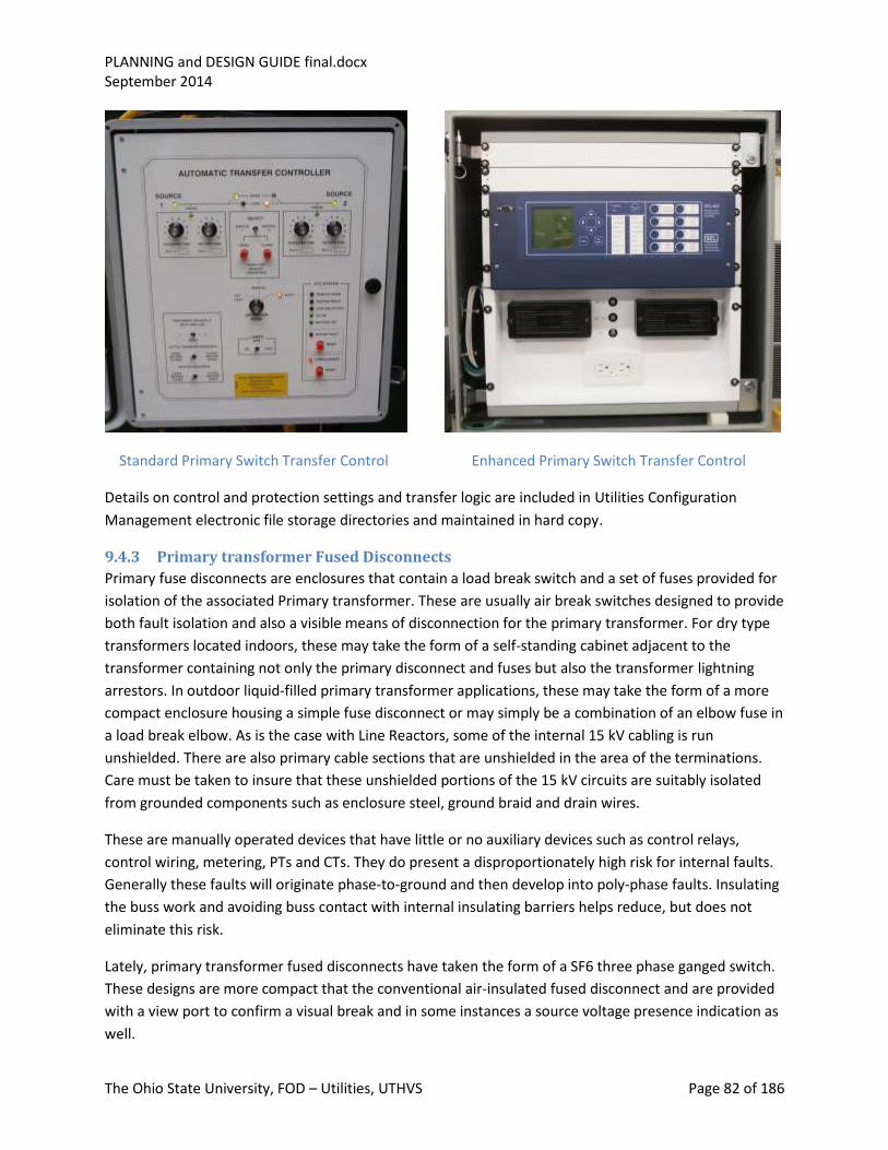
PLANNING and DESIGN GUIDE final.docx September 2014
The Ohio State University, FOD – Utilities, UTHVS Page 82 of 186
Standard Primary Switch Transfer Control Enhanced Primary Switch Transfer Control
Details on control and protection settings and transfer logic are included in Utilities Configuration
Management electronic file storage directories and maintained in hard copy.
9.4.3 Primary transformer Fused Disconnects
Primary fuse disconnects are enclosures that contain a load break switch and a set of fuses provided for
isolation of the associated Primary transformer. These are usually air break switches designed to provide
both fault isolation and also a visible means of disconnection for the primary transformer. For dry type
transformers located indoors, these may take the form of a self-standing cabinet adjacent to the
transformer containing not only the primary disconnect and fuses but also the transformer lightning
arrestors. In outdoor liquid-filled primary transformer applications, these may take the form of a more
compact enclosure housing a simple fuse disconnect or may simply be a combination of an elbow fuse in
a load break elbow. As is the case with Line Reactors, some of the internal 15 kV cabling is run
unshielded. There are also primary cable sections that are unshielded in the area of the terminations.
Care must be taken to insure that these unshielded portions of the 15 kV circuits are suitably isolated
from grounded components such as enclosure steel, ground braid and drain wires.
These are manually operated devices that have little or no auxiliary devices such as control relays,
control wiring, metering, PTs and CTs. They do present a disproportionately high risk for internal faults.
Generally these faults will originate phase-to-ground and then develop into poly-phase faults. Insulating
the buss work and avoiding buss contact with internal insulating barriers helps reduce, but does not
eliminate this risk.
Lately, primary transformer fused disconnects have taken the form of a SF6 three phase ganged switch.
These designs are more compact that the conventional air-insulated fused disconnect and are provided
with a view port to confirm a visual break and in some instances a source voltage presence indication as
well.

PLANNING and DESIGN GUIDE final.docx September 2014
The Ohio State University, FOD – Utilities, UTHVS Page 83 of 186
9.4.4 MV Starters
MV Starters are used in applications that don’t justify the application of metal clad switchgear
technically or economically. They come in a variety of configurations including ones with integral soft
start capabilities. They are basically a fused disconnect in series with a contactor. The contactor can be
an electrically held device which will be controlled from an AC control circuit powered from an integral
CPT. The contactor can also be a by-stable device whose closure is controlled by an AC control circuit but
whose tripping is usually dependent on some form of specialized tripping device that integrates a
capacitor trip device (CPD).
The electrically held version is basically just a large motor starter contactor similar to what is commonly
used in LV motor control. If power is interrupted, the starter drops out and the motor stops. When the
power is restored the motor will either restart or remain off depending on the design of the control
circuit. There is no need for a separate trip coil. The starter control circuit can be wired with a protective
relay that replicates the operation of a motor overload and shuts down the motor. These are generally
applied directly to start large motors.
The mechanically held version resembles a conventional circuit breaker in that there is a close circuit
and a trip circuit. Both rely on the availability of AC to close and trip however the trip also has the ability
to trip for a short period after the loss of power through the use of a capacitor trip device. These are
generally applied to power drive systems such as variable speed drives, or equipment that would be
turned on or off infrequently, or they may be applied as a CB substitute.
The starter portion of both of these versions is designed to handle switching starting and running load.
Faults must be cleared by fuse interruption as the contactors are not designed to interrupt large fault
currents. The fuses also serve to reduce arc flash levels in some instances.
Starters that include a soft start provision are considerably more complex than either of the previously
mentioned versions. There are a variety of approaches to soft starting motors. The most common is a
solid state starter that applies a gated reduced voltage which results in lower starting currents but
correspondingly longer starting times. Other methods in common use do reduced voltage starting by
inserting a reactor or using a delta Y switching scheme to limit starting current. Soft starting should be
applied only when the distribution system requires it to insure adequate voltage regulation for the
balance of system loads during starting of large motors. A general rule of thumb is that a 5% buss
voltage reduction on starting large motors is acceptable for most applications, two percent when loads
are powered directly off the 13.2 kV Distribution system and power quality for building loads is the
major concern.
The advantage of using MV starters over metal clad switchgear is cost. When metal enclosed switchgear
designs were air magnetics, wear was also an issue and there was an advantage to applying MV starters
in applications with frequent starting duty cycles. With the general use of vacuum switching equipment,
this is less an issue. The disadvantage to applying MV starters lies in their potential for single phasing
due to fuse failure and the general limitations inherent in their construction. There are serious

PLANNING and DESIGN GUIDE final.docx September 2014
The Ohio State University, FOD – Utilities, UTHVS Page 84 of 186
limitations to what can be provided in current transformers and customization due to their compact and
economy driven designs.
9.4.5 LA application
The 13.2 kV distribution system is built to a 95 kV BIL. However, to limit transient over voltages (surges)
on the cables systems, some of which is older technology, we apply lightning Arrestors (LAs) at 10 kV 8.4
kV MCOV. Because the MV distribution system is an underground cable system, transient overvoltage is
an issue primarily where cables terminate on devices with high characteristic impedance such as a
reactor, primary switch, transformers or generator without surge capacitors. This consideration governs
the choice of LA locations.
Portions of the system such as the substation main transformers are designed to a higher BIL (110 kV).
The LA in these applications has a higher voltage rating. Portions of the MV system that can be powered
from standby generation and operate independent of the main substation transformers, may
experience significantly higher voltage unbalance to ground during faults than experienced on a solidly
grounded system. In these instances, LAs are applied with an even higher voltage rating to avoid
arrestor spill over during system ground fault conditions. For these applications, refer to the appropriate
IEEE standards for application of surge protection.
9.4.6 Grounding Provisions
Provisions for equipment grounding fit either of two different classifications: power grounding and
safety grounding. The campus MV system is a solidly grounded system. The grounding occurs back at the
source transformer(s). Distribution-system loads are delta connected and are not a source of additional
ground currents in the event of system ground faults. Each three phase feeder is accompanied in its
conduit by one 4/0 600 V insulated ground cable which is grounded at both ends along with the
individual phase conductor shield drains (termination points and splices). Each manhole contains
supplemental grounding in the form of a ground rod. Safety grounding is performed on all terminal
equipment containing MV circuits. Where power grounding is directed toward establishing a low
impedance return path for ground faults, safety grounding is directed toward reducing touch potentials
to safe levels during operation as well as system fault conditions.
The integrity of the power grounding system is safeguarded by requiring cad welding, crimped
terminations, multiple bolting where terminations are subject to removal for maintenance, and
provisions for corrosion protection. In addition, grounding of electrical components requires two
independent paths to ground to assure that inadvertent disconnection of a ground connection will not
result in a grounding failure and personnel and equipment risk. Because power grounding involves very
large currents, grounding impedances must be kept very low. Enclosure grounding on the other hand
seldom is directly involved with high currents but is needed to address touch potential issues. It is
focused on keeping the ground potential environment uniform to avoid gradients that could elevate
touch potentials above safe levels. A good example is the treatment of fences around high voltage
substations. The station ground grid is made up of a matrix of ground cables and grounding points
designed to even out step potential during station ground faults. This grid also extends three or more
feet beyond the station fence and is bonded to the fence itself. This assures that anyone touching the

PLANNING and DESIGN GUIDE final.docx September 2014
The Ohio State University, FOD – Utilities, UTHVS Page 85 of 186
fence during a station fault will have their feet at the same potential as the fence and their hands. A
similar arrangement is employed at and around primary switches mounted in the open on pads.
Requirements for ground resistance, terminations and grounding cables are given in the BDS.
Main Transformer Grounding Main Control Panel Lower Ground Buss
Main Control Panel upper ground buss Vault Ground Buss

PLANNING and DESIGN GUIDE final.docx September 2014
The Ohio State University, FOD – Utilities, UTHVS Page 86 of 186
Distribution System Ground Cable Grounding Electrical Tray Grounding
Non Segregated Bus Duct Grounding MV Tray and Cable Grounding
WCS Equipment Enclosure Grounding Lightning Protection
PLANNING and DESIGN GUIDE final.docx September 2014
The Ohio State University, FOD – Utilities, UTHVS Page 87 of 186
9.4.7 LOTO Provisions
Working around MV systems and equipment is hazardous work and requires extra attention to detail
and conformance to safety rules. Lock Out Tag Out (LOTO) and adherence to other safe work practices
are our only effective defense against MV accidents that could result in serious injury to personnel and
damage to electrical systems and equipment. That said; procedures and practices are only one portion
of an effective safety program. Equipment design is another. And training is a third. Utilities maintains
procedures governing safe work practices in production facilities, in the substations and throughout the
MV distribution system. We also have developed and promulgate the Utilities Project Safety and Health
Guide for use by construction personnel and Utilities personnel on Utilities construction projects.
In addition to safe work practices, equipment design must support LOTO. Typical examples are
provisions for grounding of power circuits, provisions for in-service inspection and switch status
determination, isolation of control and power components, controlled access to critical control and
safety features and design consistency for points of operator access for operation and maintenance.
Taking this philosophy one step further, the distribution system design must reflect this same bias
towards consistency. Operator familiarity with the design becomes limited when the system design
includes a large number of diverse system arrangements and divergent conventions for color coding and
the like. Examples of accepted standards and conventions include red meaning energized, green
meaning off or safe, switch action or position to the right meaning CB close, start, initiate or run, switch
action to the left meaning CB open, stop, shutdown or reset/block.
The third component, training, depends on the first two to be effective.
9.5 Unit Substations Unit Substations are a common Primary service configuration and popular for the larger services on the
main campus. In general they include a primary fused disconnect, a primary transformer (typically dry
type), and switchgear containing the secondary main CB or fused disconnect and the Low Voltage main
switchgear. A double-ended version of this includes two of the above and the addition of a tie CB. The
standard relaying on the source CB for the Primary circuits puts an upper limit to the size allowed for the
primary transformer at 2500 kVA.
9.5.1 Approved configurations
Since the unit substation is an integral part of the building primary service, Utilities takes an active role
in applying and reviewing the designs. The BDS has requirements for the design of the switches,
transformers, fusing and the design and layout of the secondary switchgear. There are a wide variety of
acceptable configurations that may be applied depending on the criticality of service and the need to
perform maintenance without service interruption. Some more common and acceptable unit sub
configurations and contained in the BDS DIV 33. However, common to all are a few requirements. Strict
conformance to these design requirements insure reliability of service and, once the primary service is
turned over to Utilities after startup and acceptance, insures that Utilities will be able to operate and
service the equipment in a timely and efficient manner.
PLANNING and DESIGN GUIDE final.docx September 2014
The Ohio State University, FOD – Utilities, UTHVS Page 88 of 186
9.5.2 Equipment ratings
Key equipment ratings are given in BDS DIV 33. In some cases they exceed what is typical of most
commercial installations and what is familiar to most associate engineering companies and installation
contractors. The requirements listed in BDS DIV 33 by-in-large are the result of a conscious effort to
factor life cycle costs and reliability concerns into the design of the building service. As the ultimate
owner operator of the equipment, Utilities has a vested interest in an installation that will perform
reliably and economically throughout the life of the facility served. Utilities needs to be responsive not
only to the needs of the individual facility but also the needs and operating cost to the distribution
system customer base at large.
9.5.3 Application requirements
The Unit Substation application obviously needs to be responsive to the facility needs. Beyond this, the
application needs to fit into an application envelope of requirements that insure that it will not pose an
undue risk to other customer’s facilities powered off the main campus MV distribution system.
Chief among the considerations for a new facility on the distribution system is equipment protection
coordination. The primary distribution system is designed to serve up 2500 kVA primary transformers
without the need for any additional sophisticated relay protection system. For this reason, building
primary service transformers are limited to 2500 kVA base self-cooled rating. Utilities also requires that
the secondary protection be coordinated so that the primary transformer fusing will not be called upon
under fault conditions to clear a fault on the low voltage side of the primary transformer beyond the
secondary main CB.
Another key consideration is that the primary transformer and switchgear be designed to support safe
and economical operation. The no load losses of the transformer are a chief concern as they are swept
up in miscellaneous system losses and become a part of the cost of electrical service shared by all
customers. The quality and dependability of the primary switching equipment, likewise is a key concern
as it relates to the serviceability of the equipment. Its replacement costs, should it fail, would have to be
borne by Utilities and ultimately be reflected in their operating costs and borne by the broad base of
customers.
The design’s impact on operating personnel and their safety is likewise a key concern. MV equipment
design features compatible with utility operating and safety procedures is a requirement. This extends
into design features for primary voltage switchgear as well as design features required of the low
voltage secondary switchgear where exposure to arc flash is a greater risk. An example of this is the BDS
requirement that all secondary main and tie CBs be metal-clad, draw-out design, equipped with the
wired provision for remote trip and close. This is to insure that the operator can stand outside of the
hazard area (arc flash) when operating the gear. This is a particularly valuable feature when the gear is
not routinely inspected, maintained or calibrated.
9.6 Line Reactors OSU employs three phase air core series line reactors on all its 13.2 kV radial street feeders to limit fault
currents to acceptable levels for the primary switchgear at the building services. These are indoor VPI

PLANNING and DESIGN GUIDE final.docx September 2014
The Ohio State University, FOD – Utilities, UTHVS Page 89 of 186
designs and come in two versions. Some are mounted in a configuration close coupled with the feeder
breaker (reactor breakers). Others are self-standing in a general purpose ventilated enclosure located in
the substation vaults or in the case of Smith substation, located in the attic space above the switchgear
area.
600-Ampere 15 kV Class Reactors
9.6.1 Application
These line reactors are rated for line voltage and add 0.5 Ohms per phase in series with the feeder-to-
limit fault currents to under 10,000 Amps. The reactor breaker application and all the self-standing
reactors supplied by the switchgear upgrade performed in the early 2000’s were rated 400 Amps
continuous current. However, because of cooling problems encountered in the reactor breaker design,
load in excess of 300 Amps in this configuration requires the use of portable booster fans. Application of
booster fans to the self-standing reactor design would only be considered to obtain an extended rating
in excess of 400 Amps to match the newer reactor design rating. Newer self-standing reactors added
since the original upgrade are rated 600 Amps continuous with a 750 Amp short-time 4-hour rating.
Both versions of the self-standing reactors are self-cooled for reliability reasons but are constructed in a
configuration that could accommodate some level of forced (fan) cooling if determined to be necessary.
9.6.2 Construction
Line reactors are air core copper VPI insulated three phase units that are designed to be air cooled.
Terminations are arranged for a line and load side with LA’s cabled to the load side for the protection of
the attached feeder cables. The construction involves stacking three single phase reactor coils on top of
each other on insulators with a support frame and termination support structures made of reinforced
insulating fiber board. The whole three phase array is housed in a ventilated enclosure along with cable
supports and LAs. Operating at line potential, the voltage stresses are across the coil supports between

PLANNING and DESIGN GUIDE final.docx September 2014
The Ohio State University, FOD – Utilities, UTHVS Page 90 of 186
phases with little voltage drop across the reactor coil itself line to load except under fault conditions.
Aside from the potential for moisture intrusion or excessive dirt accumulation, this construction poses
little likelihood of dialectic failure. The weak point in the design is the LAs and their MV cables. These
cables, because of space constraints, are not shielded and pose a flashover hazard if not adequately
separated from ground potential such as the walls of the enclosure or the power cable shield drains. A
failure of the LA cable or the LA itself will, in almost all cases, result in a catastrophic failure of the
reactor due to the construction of the reactor and the flux patterns produced by the fault current. For
this reason extreme care must be taken in the placement of these LA leads and the routing of shield
braid and drain wires.
9.7 MV Cable The medium voltage cable used throughout the distribution system and in MV applications within the
power plant and allied facilities is high quality 133% EPR-insulated, shielded, low-smoke, zero halogen
jacketed cable. Some other cable constructions have been used in the past and still are in service but in
limited quantities. These constructions include both XLPE and PILC. Strict control of cable construction,
insulation systems and termination/splicing is key to obtaining low service failure rates and high service
availability. Strict adherence to the BDS requirements for materials and constructions facilitates stocking
of spare cable and termination/splicing kits which aids in reducing the duration of forced outages
requiring circuit repair.
9.7.1 Application
The main campus MV distribution system is an underground radial distribution system. The system of
manholes and buried duct banks provide both physical protection and limit externally generated voltage
surges such as can be anticipated from lightning activity. The distribution system can be differentiated
into three classes of circuits: mains, laterals and load ways. The cables used in each of these
classifications are the same as far as insulation, shielding and jacket materials used. The gauge of the
conductor will be different in most cases, with the heavier gauge used in the mains and a lighter gauge
in the laterals and load ways.
While the distribution system cable application is exclusively 13.2 kV, there are some 5 kV cable
applications within the power plant and central chiller facilities.
9.7.2 Construction
MV cable construction has been standardized on the main campus as have the approved termination
and splice kits. MV cables are insulated with 133% rated EPR, with a copper foil 25% overlapping shield
and low smoke zero halogen jacket. The specifications for this cable are given in the BDS. There are
instances where the low smoke zero halogen requirement has been waved. This requirement is
primarily driven by the risk to sensitive equipment and personnel in substation and in tenanted areas.
Substation and substation vaults are prime examples. We have relaxed this requirement in a select few
instances where we can be sure that the cable in question will not be introduced into such areas either
by the project or indirectly through restocking of utility lent cable or through the use of leftover cable
from projects that has been turned over to utilities rather than scrapped.

PLANNING and DESIGN GUIDE final.docx September 2014
The Ohio State University, FOD – Utilities, UTHVS Page 91 of 186
In addition to standardizing on the cable construction, the cable sizes are standardized. main circuits are
conductored with 500 kcm. Reserves (third or standby feeders) are conductored with 750 kcm. 4/0 is
used for laterals and load ways in most cases. With a few specific exceptions, these three sizes are the
only sizes applied on campus. This is done to facilitate stocking of cable, termination kits and
termination hardware.
Power plant applications allow more latitude in cable sizes but not in constructions. Plant and central
chiller applications have to cover a wide range of load sizes and involve more space restrictions, hence
the latitude in cable sizing. Spare parts and materials inventory management is also less an issue
compared with the campus MV distribution system at large.
Cable Term Breakout
9.8 Primary Metering As a general rule metering is applied to the main substation buss main feeds and circuit feeders (at OSU,
WCS and Smith) at the source breakers but not at the individual building services. While there are a few
locations on campus where primary side metering has been applied to building services, this practice is
no longer permitted. Primary metering requires the attachment of potential transformers to the primary
system with the associated fusing and cable connections as well as providing an enclosure to contain the
PTs and associated cabling and wiring. This is all undesired exposure and also serves to complicate the
process of cable high potting and fault location. The reference design for service metering places the
metering CTs and PTs on the low voltage side of the primary transformers, usually in the LV switchgear.
The selection of the style and manufacturer of the meter is done by standards maintained by Energy and
Sustainability and needs to be compatible with the interfacing communications system and monitoring
software. The metering applied is three phase metering.

PLANNING and DESIGN GUIDE final.docx September 2014
The Ohio State University, FOD – Utilities, UTHVS Page 92 of 186
3-Phase Meter on Switchgear
Metering applied to building services and the MV distribution system has been standardized, with the
requirements stated in the BDS. This standardization is required to facilitate data collection and limit the
need to accommodate diverse protocols.
9.9 DC Battery Systems
9.9.1 Application
DC battery systems are applied in instances where a source of control or protection power is required
before, during and after a power circuit failure or outage. There are two versions. One is the central
battery application. The other is an equipment-based battery/charger, applied to provide transfer
control, protection and monitoring at primary switch locations around the distribution system. These
applications have similarities but differ widely in design detail, maintenance and operational
requirements. A major difference between these applications is in battery technology. Central battery
systems are built around a high capacity station type battery with a design life of twenty or more years.
The equipment-based battery technology is similar to the technology applied to emergency lighting
battery packs. These batteries are typically lead acid or gel cell batteries with a maximum service life of
5 years or less. Central battery systems are designed and installed with the intent to perform regular
surveillance of cell condition and periodic tests to confirm overall battery condition and capacity. The
lead acid and gel cells are throw-away and treated as such. They are not generally surveilled but simply
replaced programmatically on a three to four year interval. Some critical applications may have their
charging systems monitored or have a self-contained, self-test feature.

PLANNING and DESIGN GUIDE final.docx September 2014
The Ohio State University, FOD – Utilities, UTHVS Page 93 of 186
WCS battery area
9.9.2 Construction and sizing
Central station DC systems such as are applied to the main electrical substations (OSU, WCS and Smith-
McCracken) are relatively large central systems comprised of a large wet cell station type battery (100 to
300 AH, 125 VDC nominal voltage), battery charger and battery metering, with a central distribution
system, and cross-ties to a back-up or redundant battery or battery system. Such systems are central to
the facility and supply power to the facility DC controlled switchgear as well as critical AC (inverter)
systems and other electrical components and systems that would be required to operate through an AC
power disturbance. BDS requirements include a minimum 8-hour coping capability. The battery is sized
based on a load profile that reflects a credible scenario of automatic operations followed by a series of
manually-initiated operations requiring the availability of station DC power. The weakest link in a DC
system, such as installed at our central facilities, has historically not been the battery. It is the battery
charging. Because of this we generally include a permanently-connected, built-in spare charger. In a two
battery design, the spare charger is connected to the battery tie buss so that it can be placed into
service upon failure of either of the assigned battery chargers with a minimum of effort.
Central chiller plants also have a central battery DC system. These systems serve facility switchgear as
well as power the station uninterruptable power to critical plant control and monitoring systems. The
DC system duty requirement for these facilities may vary and is considerably shorter than for a central
substation. In chiller plants, the largest single load is the critical AC inverters. These are typically
required to operate for up to an hour without station AC available, after which the inverter load can be
removed from the battery and the battery allowed to continue to power miscellaneous plant DC loads
for a relatively lengthy but indeterminate period. In instances such as the SCCCP, where standby power
generation is available, power restoration to battery system chargers is automatic, usually in the ten to
sixty second time frame. Because of the limited duty requirement and the minimal need for DC when
the facility is down for loss of power, these facilities usually have only one central battery. If another
facility with central DC is nearby as is the case at the South Campus Central Chiller Plant, a backup cross-
tie may be provided. This can be helpful during battery discharge testing, equalizing or battery cell
replacement but is of limited value for extended battery outages. Depending on the arrangement of
incoming MV power, one-battery systems may need to have some back-up source of locally generated

PLANNING and DESIGN GUIDE final.docx September 2014
The Ohio State University, FOD – Utilities, UTHVS Page 94 of 186
AC to maintain or restore battery charge after a sustained facility outage where its normal AC power
source was unavailable for a prolonged period. This can be provided by a small, manually operated,
portable generator in most cases. Once power is restored to the building primary service, battery
charging can be returned to the central DC system main charger.
9.9.3 Ancillary equipment and housing
The principal components of a central battery system are the battery, charger and distribution system.
Beyond these there are ancillary components that facilitate operation and maintenance. These are a
battery disconnect or a separate load bank connection cabinet, a metering cabinet to provide
charge/discharge status, battery voltage indication and indication of isolation from ground. In instances
where battery equalize voltage is high enough to warrant isolation from normal battery load, a separate
equalizing charger may be warranted so that the normal battery charger can be used to power the DC
system load at normal voltage levels while the battery is being equalized. This is usually not necessary as
in most central battery applications there is an alternate source of battery DC or the construction of the
batteries does not require excessively high equalize voltage.
Large central battery systems are operated ungrounded for reliability reasons. A battery ground
detector is applied to guard against prolonged operation with an inadvertent ground present. DC
systems are also routinely designed with battery voltage monitoring set to detect the battery coming off
charger. In systems with battery cross ties, since these ties are required to be de-energized when not in
use, a voltage presence alarm is also included. Typically these will be housed in one of the battery
metering compartments.
Battery enclosure design is critical to the operation of the battery. Station batteries generate hydrogen
gas. This gas in concentration can be explosive. The amount of gas being released depends on the
battery type, design and operation. As we require our batteries to be housed in an enclosure to protect
the battery from dirt as well as protect staff from inadvertent exposure to chemicals and electrical
shock/burn, there is a heightened potential of hydrogen accumulation. All battery enclosures must be
ventilated. The ventilation must be natural not forced through the use of an enclosure vent fan. The
amount of ventilation needed depends on the type and construction of the battery. In extreme cases
the enclosure and environment may require some external venting. This may be forced if there is
adequate provision for dilution of the hydrogen before entering the area of the fan or blower.
9.9.4 Equipment based Battery Systems
The MV distribution system has some installations that depend on DC for local control needs. The most
common are primary select switches where the auto transfer feature of the switch relies on local
battery power for executing a transfer between normal and alternate primary sources. In such cases, a
local source of AC power is used to charge and float a local 24 V battery. The AC source may be from the
building or facility being served, or from a CPT powered off the primary switch itself. These installations
are very limited in size with a limited duty cycle. In critical applications where remote telemetry is
available, battery condition monitoring is also applied. In most instances, the DC and transfer controls
are optional and the switching operation will be manually initiated making the motorized operation
more a convenience than a necessity.

PLANNING and DESIGN GUIDE final.docx September 2014
The Ohio State University, FOD – Utilities, UTHVS Page 95 of 186
The enhanced feeder relay application makes more critical use of these local equipment battery
systems. In these applications, not only are the transfer controls powered from DC. The load way
tripping is also performed by protective relays powered from the DC system as is the supervisory
(Normally the RFI tripping would be performed by solid state trip units powered from the current in the
load way). These installations generally have two sources of AC powering the enhanced relay package.
Each enhanced relay package has one 24 V DC battery whose state of charge is continuously monitored.
The enhanced relay package is dependent on DC for its control, protection and supervisory functions.
For these installations, battery condition, transfer control and protectives are continuously monitored
centrally as are primary switch and RFI positions.
Equipment-based DC systems may be operated grounded or ungrounded. Since they are contained
within the primary switch or close-coupled to the switch, there is little advantage to operating
ungrounded. However from the safety standpoint, there is no advantage to grounding either. Present
practice is to ground and fuse the AC supply to the system but allow the battery DC to float. Under
voltage detection is applied to alarm, but no ground detector is applied as would be the case in the
central battery design.
The battery systems in these applications are contained within the switch enclosure or external to the
switch enclosure in a separate enclosure. The batteries are sealed construction and the enclosures are
not vented for hydrogen evolution.
9.10 Standby Power Systems Standby power is the generic term for standalone power systems that are applied to instances where
power in part or in full is to be restored from an independent power source after a limited delay, usually
in the order of 60 minutes or less. Emergency power, in contrast, is the generic term applied to
independent power sources that can be placed into service and restore power in a relatively short time,
typically in the order of ten seconds or less in compliance with some regulatory or code requirement.
Typically emergency generation on campus is a building-by-building feature while standby power tends
to be larger and more centralized.
Smith Standby Diesel Generator

PLANNING and DESIGN GUIDE final.docx September 2014
The Ohio State University, FOD – Utilities, UTHVS Page 96 of 186
9.10.1 Application
There are three permanently installed central standby power sources on campus. Two are associated
with McCracken Power plant and intended to support power plant steaming operations and Smith
Substation. The remaining installation is dedicated to the South Campus Central Chiller Plant which, in
turn, supports the major Med Center’s cooling needs. These sources of standby generation are
integrated into the MV distribution in their respective buildings or allied facilities with the exception of
one unit (1500 kW) which generates at 480 VAC and can be called on to supply power to McCracken
Power Plant 480 V Sub 2. The other two sources are made up of two standby diesel generators each,
one at Smith Sub (two 2300 kW DG sets) and one in a standby power house north of McCracken Plant
(two 2500 kW DG sets). The McCracken 1500 kW set is manually started and paralleled. The other two
installations are designed to start on loss of utility. They then island a portion of the MV distribution
system at McCracken PP and the SCCCP respectively. Both initiate a load shedding at their respective
facilities, isolate from the normal utility sources and re-energize a limited portion of their respective
facility load. While typical building emergency generation uses transfer switches to align the DG sets to
their emergency loads, the standby generators power the building distribution busses directly. This
allows for a more orderly power restoration when normal station power returns without any need to
de-energize loads a second time during realignment (synchronizing) to the normal feed.
Standby generation is designed to operate independently from the utility when it is called into service
and in parallel with the utility for system restoration and periodic surveillance load testing.
9.10.2 Ratings
Standby power system ratings are determined by the loading requirements. Typically the standby
system will have a defined loading schedule. On small distribution systems, this may be accomplished by
segregating the portion of the total system load to be assumed by the standby system and arranging for
its assumption through a system reconfiguration such as can be performed with a transfer switch or
transfer of a buss with the intended standby loads. In a utility environment this approach turns out to be
overly restrictive or impractical to accomplish; particularly if standby loads are already arranged so that
in normal system operations they meet predefined redundancy or separation requirements. In such
cases, the standby generation has to be made an integral part of the distribution system and the loading
dependent on some level of load shedding and load sequencing.
Standby system sizing is determined by the magnitude of the block or unshedable residual buss load, the
size of the largest load and the size of the total load to be assumed by the standby generation. A good
rule of thumb is that the block load should be less than half the base rating of the engine generator set.
It will load at the beginning of the loading sequence as soon as the first generator comes on line.
Subsequent sequential loading will need to be such that the incremental loading steps do not reduce
system voltage below minimum voltage levels needed to keep running motors from stalling or tripping
on low voltage. Large loads will tend to have more of an effect later on in the loading sequence than
they would earlier. Modern engine control systems are good at maintaining speed and recovering from
speed fluctuations caused by load additions. Voltage regulation likewise, is aided by modern solid state
excitation systems, however each have their limits. Large load additions such as big resistive load
changes or motor load changes are a test of the engine control systems. Starting large motor drives

PLANNING and DESIGN GUIDE final.docx September 2014
The Ohio State University, FOD – Utilities, UTHVS Page 97 of 186
across the line are more of a challenge to the excitation systems as the load addition is small compared
to the increase in reactive loading. In extreme cases, it is common practice to oversize the generator to
get better voltage support during full voltage starting of large motor drives. This approach is especially
useful when these larger drives are started at the end of a loading sequence when the engine generator
set is close to fully loaded.
9.10.3 Protection
System protection can pose a challenge. The standby generation is invariably weaker than the utility
source, necessitating special attention to the relaying and its settings. Grounding on standby generators
is relatively high impedance with ground faults limited to around 200 A. Such low levels of fault current
may render protective relays too slow to be effective and result in the inability to detect a fault under
certain conditions. Maintaining coordination is difficult to impossible given that the standby generation
may be introduced at a point diverse from the normal utility feeds. It is worth considering a diverse
relaying scheme that either provides supervised low-set relaying, or takes advantage of the fact that
dependence on the standby system utilization is already one contingency in and applying a more
rudimentary relaying scheme may be the best solution to protecting the distribution system.
9.10.4 Ancillary equipment and housing
Campus standby power generation is housed in the plant, a substation or in its own service building
along with its ancillary support systems: fuel oil handling, transfer pumps and day tanks; starting air
system, cooling systems, paralleling controls and HVAC. In the larger standby power applications, these
ancillary systems are powered from the generator paralleling buss and may have an alternate power
feed from a second building source or LV distribution. The advantage of having the ancillary equipment
powered from a source closely aligned and powered from the standby generators is that the power
dependencies are limited and less subject to alignment or operator error. Having a back-up source is
most useful during maintenance of the paralleling buss and aux transformer.
9.10.5 Standby Power System Operation and Testing
The operation and testing of a standby power system differs in many regards from what is typically done
for emergency power. Standby power of a scale applicable to facilities on campus is generally integrated
into the existing MV system and does not rely on transfer switches to realign critical loads to the
generation. Loading may be automatic to a degree; however continued operations and loading activity is
manually initiated as is system restoration. Typically, standby system starting and initial load
reconfiguration (load shedding and utility shedding) is performed automatically. Beyond the loads
automatically assumed (block loaded), the remaining loads are brought on by operator action assisted
by the facility automation; and the MV distribution system is re-configured to meet changing equipment
power needs by University personnel manually. Likewise system restoration involves a series of
manually initiated sequences that return facility MV busses to the utility sources and then run out and
shutdown the standby generation.
Testing for a standby power system is also different and more complicated than for an emergency
system. With the emergency power system, dedicated load busses are common and entire systems,
generation and associated load, can be tested as a unit. The use or addition of load banks is common.

PLANNING and DESIGN GUIDE final.docx September 2014
The Ohio State University, FOD – Utilities, UTHVS Page 98 of 186
Standby systems, since they are integrated into the facility MV distribution, are more difficult to
routinely test without disrupting facility operations. For this reasons full functional facility tests are more
likely to be a seasonal rather that a routine affair. Routine testing is conducted by paralleling the diesel
generator to the utility grid, with the testing more or less limited to engine generator and ancillary
systems. In the absence of any special requirements, this testing is done monthly. Testing is conducted
under significant load; 75 to 100% Load to be representative of actual loading conditions and for the
material condition of the engine. Prolonged operation at low load can result in engine deposits that will
reduce engine life and limit engine output.
9.11 Relay Protection
9.11.1 Basic philosophy
Protective relay application to MV distribution systems is somewhat counter intuitive. The term
“protective” needs some clarification. It is commonly held that protection is focused on protecting the
system component being relayed or fused. This is not generally the case. MV System protection is more
often than not applied to protect the distribution system from a failed component than the other way
around. The vast majority of protective relay and fuse applications on the campus MV distribution
system are “fault” rather than “overload” applications. Protective relays are applied to clear a fault off
the system rather than protect equipment from overload. This rationale is founded on the principle that
system reliability trumps individual system component longevity. Adding “overload” devices throughout
the MV Distribution system would serve the purpose of insuring individual components will not suffer
loss of design life as the result of experiencing abnormal system conditions, but at the expense of risking
tripping off buildings and jeopardizing customer’s interests. In such an application the risk of false
tripping significantly outweighs any advantage gained from protecting components from what amounts
to low probability events on an engineered and managed system.
Protective relays come in a variety of forms. We apply two basic forms commonly on campus: Time-
overcurrent and differential. Time-overcurrent is the most common and is applied as primary protection
for street feeder circuits as well as secondary protection to equipment whose primary protection is
afforded by differential relaying. It is relatively simple and straight forward to apply and relatively
inexpensive. The time overcurrent relay in its most prevalent form is a multifunction relay that can
provide, instantaneous tripping as well as definite time delay and the range of inverse time delay
tripping. Differential relaying is a bit more complex and expensive. It is applied to applications where the
relaying needs to be very sensitive, selective and the asset being relayed is a critical or expensive asset
where fast tripping to limit fault damage is of high value. Such assets include medium and large standby
or co-gen power generators, main transformers and main distribution busses. We also commonly apply
differential relaying to connecting feeders such as the main feeds to Smith and SCCCP from OSU Sub. In
these applications, the differential relays provide extremely fast fault detection and tripping as a first
zone of protection on the feeder. This is important as the second, or backup protection, is afforded by
time overcurrent relays that have to be slowed down to allow coordination with a number of
downstream protective relays and interruption devices.

PLANNING and DESIGN GUIDE final.docx September 2014
The Ohio State University, FOD – Utilities, UTHVS Page 99 of 186
Time overcurrent relays have a variety of characteristics that can be selected to address a range of
protection requirements but are grouped into two main classifications, equipment overload protection
and system fault detection. The overload classification is again sub grouped into classifications based on
the equipment to be overload protected, e.g. motors, transformers, etc.
Differential relays are also grouped into classifications based on the equipment to be relayed. This is
necessary because of the unique properties and applications of the equipment. Since differential relays
are relatively expensive and complex, there is also an economic decision involved in a decision to apply
them. We apply differential protection to main substation transformers, our large standby generators (>
2000 kVA) and main switchgear. We may apply differential protection for other MV buss application and
smaller transformers 5 MVA and larger if the economics, relaying effectiveness and the equipment itself
supports it. Differential protection for busses is commonly determined by the gear itself and its ability
to support the additional numbers of CTs needed for the application. This is not a problem for main
switchgear with conventional metal-enclosed breakers in the buss lineup, but may be an issue for the
lighter duty or more congested MV gear with starters. Differential relays are generally paired with lock-
out devices to provide the necessary trip contacts to trip multiple devices, a means for testing and an
assurance against inadvertent or accidental re-energization that could result from buss realignments. All
of this will add cost and complexity to the differential relay installation.
9.11.2 Equipment protection
Equipment protection generally resolves to protect parts of the system from the failure of another part
of the system. The key to this is rapid and effective isolation of failed components to minimize
disruption to system operation and remove the potential for collateral damage to other system
components. An example would be circuit feeder protection. Pick-up to trip is set at 800 Amps, twice
the full load rating of the feeder cable. Obviously this pick-up value is not chosen to protect the cable or
its source breaker current limiting reactor for that matter. The value is safely out of the range of circuit
load transients however. A circuit fault is typically in the 4,000 to 9,000 Amp range. Protective relay
detection and breaker clearing in less than 12 cycles is achievable with this pick-up. The relay operation
is to trip the circuit feeder breaker, isolating the feeder and removing it from its source buss(s) and
source transformers. The faulted feeder cable or component has already failed, however the buss and
transformer are left in service and sustain no significant damage from the fault event. The same can be
said for any component upstream from the fault which in this case would include reactor and cable.
9.11.3 System coordination and selectivity
The objective of the protective relay application is to remove faulted equipment as rapidly as possible
without inflicting false tripping.
A common approach taken to achieve speed is to apply “differential” relaying. This approach is one
where a boundary can be established and the current that enters and leaves can be measured and
compared. If everything balances out there is no fault in the area. If there is an unbalance, there is a
potential for a fault. The relay applied is designed to measure these currents and determine, based on
the application, whether there is a fault present and not some transient phenomena or measurement
error. Because the boundaries are pre-established and there is no need to wait out the other relays, this

PLANNING and DESIGN GUIDE final.docx September 2014
The Ohio State University, FOD – Utilities, UTHVS Page 100 of 186
form of protection can be very fast and very sensitive. The applications that use this approach to
protection are differential protection for transformers, busses, generators, motors, and main
distribution feeders (leads). This approach is applied in overlapping areas of protection in our
substations and for MV distributions in the plants as a first layer of protection. In each case the faulted
area (zone) is isolated to protect the surrounding zones.
Another common approach is to apply coordinated overcurrent tripping using protective relays that can
detect fault currents and send a trip signal that factors fault current magnitude, type of fault (phase or
ground) and other factors such as alignment of circuit components or the status of other protective
relays into the time it waits to generate the trip signal. Referred to as time overcurrent relays, these
relays can be set to form tripping zones that are coordinated so that their tripping time delays allow the
relay closest to the fault and its isolation device (CB) to operate first, and so on down the line. This
approach is popular for a variety of reasons. They are inexpensive, easy to set, have multiple features
beyond the time overcurrent feature and are reliable. On the negative side, the time coordination tends
to make the relay tripping times lengthen out the closer the relay is to the power source which can be a
problem for large systems. The standard approach taken for MV distribution stations on the main
campus is to apply differential relaying as the primary protection system and time overcurrent as a
second or back-up protection. Feeder circuit protection is the one major exception to this rule.
9.11.4 Arc Flash and LV Considerations
The main campus MV distribution system is an underground radial system. It is above ground only at the
main substations and at the primary service connections. This design provides minimum exposure to the
public and minimizes the effects of environmental events such as wind storms and icing. It does have
some potential interaction with the public at manholes however. To minimize the risk associated with
this interaction, fault durations are kept a short as possible. Fault magnitudes are limited by design to
under 9000 Amps by the application of fault current limiting reactors, making fault clearing times the
key determinant in risk for exposure to arc flash effects and related phenomenon. Most faults initiate as
phase-to-ground faults. Keeping fault clearing times under 12 cycles has the advantage that the
likelihood that a phase-to-ground fault will develop into the more powerful phase-to-phase/three phase
fault is greatly reduced.
Individual primary services are a second exposure point for the public. As the result of a recent program
to replace the older outdoor air break primary select switches with modern SF 6 gas insulated switches,
this risk has been greatly reduced both outside the buildings and inside the buildings being served.
Exterior to the buildings, all switches are sealed, welded construction. Termination areas are dead-front
and metal enclosed. Within the buildings there are still some remaining air break switches in the form of
primary select and primary fused disconnect switches. Arc flash risk has been reduced at these locations
by the application of resettable fault interrupters (RFIs) in SF 6 gas switches serving the buildings; and by
the installation of fused elbows ahead of the load ways into the buildings. This arc flash reduction
benefit also extends to the low voltage portions of the primary service, however arc flash exposure at
these locations remains high and switching restrictions may apply.

PLANNING and DESIGN GUIDE final.docx September 2014
The Ohio State University, FOD – Utilities, UTHVS Page 101 of 186
9.11.5 Protective Relay Applications on Primary MV Distribution
9.11.5.1 Introduction
Protective relays are specialized devices designed to detect and take action to provide protection for
personnel and equipment. There are some very common misunderstandings surrounding the
application of protective relays. The first stems from the name “protective”. In many applications the
name will be given to the device applied to isolate a faulted piece of equipment or portion of a circuit,
when in fact the protective action is to “isolate” not “protect”. The protection afforded is to the
upstream system from the effects of the equipment or portion of the system that has already failed and
faulted. The second involves confusion as to the purpose of the protective relay in the specific
application. The most common protective function is fault detection. Second to that is protection from
overloading. In domestic applications they get equal billing as an overload and a fault usually can have
the same ultimate consequences: a fire. In utility applications, fault detection is by far the most common
application. Overload protection is relatively rare in utility practice as continuity of service is key.
Overload protection is reserved for equipment where avoidance of sustained overloads will contribute
to equipment availability or reliability such as generators, distribution transformers and motors. It is
common to see the pickup value of protective devices set at 200% of equipment rating in order to keep
them well away from the load range of the equipment.
9.11.5.2 Main Transformers:
The Substation Min transformers are relatively large 138 kV distribution station transformers. They each
have three windings, one primary and two secondaries. The secondaries are equipped with load tap
changers. Since the external utility protection does not extend in any real sense to these transformers,
our practice is to apply redundant and diverse fault detection and tripping devices.
The primary protective relays applied to these units are made up of highly specialized differential
protection capable of very sensitive fault detection while riding through large energization transients
and through faults. They also can accommodate the fact that high-side and low-side current
transformers and connections may have different characteristics, ratios and phase relationships and the
transformers themselves will be operating over a range of secondary taps and therefore transformer
turns rations. The zone of protection is from the high-side bushing CTs to the buss side of the main
feeder breakers and the secondary neutral bushing CTs.
The secondary protective relays are typically a combination of phase and ground fault time overcurrent
relays and a mechanical fault detector in the form of a sudden pressure relay. The time overcurrent
relays are relatively slow to trip as they must coordinate with downstream protective relays. These
transformers have delta high-side windings and Y-grounded secondaries. In this configuration, the
ground relays with their CT on the secondary neutral bushings must be set to observe this coordination.
However, a “high side” time overcurrent can be set with two characteristics, one to coordinate with the
secondary and downstream time overcurrent relaying, and the other a short time or instantaneous
element to trip for a current large enough that it could not have been from a secondary side buss fault.
In electrical terms, these elements are set at between fifty and sixty percent of the transformer high-
side to low-side impedance with little or no intentional time delay. This allows them to see faults in the

PLANNING and DESIGN GUIDE final.docx September 2014
The Ohio State University, FOD – Utilities, UTHVS Page 102 of 186
primary and part of the secondary windings but ignore any faults on the 13.2 kV buss work. The sudden
pressure relay is a specialized transformer protection that is mounted on the transformer tank and
allows the transformer contents (oil and nitrogen blanket to expand and contract with temperature
swings but initiate a trip if it senses a rapid change in tank pressure as would be caused by an internal
electrical fault. Since these relays are notorious for their tendency to trip from induced voltages
resulting from nearby lightning strikes, we apply them in conjunction with a high speed relay circuit in a
circuit that shunts off the lightning-induced surge and takes the sudden pressure trip directly to the
transformer lock-out relay
The transformer lock-out relay is a specialized device that takes multiple protective relay trip outputs
and trips all CBs energizing or able to energize or back feed the transformer. These are high-speed relays
that have to be manually reset.
It should be noted that the main transformers do not have anything that provides overload protection. The high-side and secondary winding (main feeder) are typically set with its pick-up at around 200% of full load current. This is done to insure that temporary overload conditions do not evolve into cascading transformer trips and buss outages.
WCS Transformer Protection Panels
9.11.5.3 Main Feeders:
The primary protection for the main feeders is provided by the transformer differential. We provide
redundant time overcurrent relays for phase and ground set to coordinate with the time overcurrent
relaying on the buss-load feeders (circuit pairs, substation ties and CAP banks). There is also a ground
overcurrent applied to the secondary winding neutral set to coordinate with the feeder time
overcurrents.
PLANNING and DESIGN GUIDE final.docx September 2014
The Ohio State University, FOD – Utilities, UTHVS Page 103 of 186
West Campus has a variant of this protection scheme where the time over current relaying is diverse.
One set of time over currents on the main feeders is as described above. A second relay is set up in what
is referred to as a “partial differential” where the main feeder and buss tie breaker CTs are summed and
put through a time overcurrent relay set to coordinate with the buss-load CB time overcurrent relays. In
this arrangement, the partial differential time overcurrent relay is set the same as the simple main
feeder time overcurrent relay. A buss or load circuit fault will result in the partial differential being
unbalanced and the relay tripping. The advantage of this arrangement is that the dual fed buss
configuration, since the partial diff relay sees twice the current as the simple main feeder overcurrent,
can be set to operate as quickly as it would in the single buss feed configuration. This is an issue
because, since the buss configuration can be single or dual, the main feeder TOC has to be set to
coordinate for the single feed. Under a dual feed buss fault, the fault current would be split between
feeders and result in a slower relay operation.
The relaying on the main feeders is equipped with a directional overcurrent feature that is not used. In
some potential future system configurations where the University might have substantial internal
generation, the situation could arise where automatic separation from the local utility would be
required. Internal generation now on campus is very limited and paralleled to the utility only for
monthly surveillance load testing.
9.11.5.4 Intermediate Transformers
The larger motor drives in the power plant and central chilled water plants have power requirements
that exceed what is customarily supplied at 480 or 575 V. Supplying them at an intermediate MV level
such as 5 kV is more efficient. This requires further transforming the 13.3 kV distribution power down to
this intermediate voltage. These transformers are typically in the 7 to 15 MVA range. If the facility is fed
directly off one of the main substation busses, the transformer is powered by a 15 kV breaker equipped
with a protection package that includes phase and ground time overcurrent relaying. In addition it has
been our practice to apply a transformer differential relay and lock out relay to detect, trip and lockout
for a fault in the transformer or its high-side or low-side leads. The lockout feature trips both high-side
and low-side CBs and blocks any subsequent attempt to re-energize.
The high-side time overcurrent relaying is set to coordinate with the relaying on the secondary feeder
and is not intended to provide overload protection for the transformer.
9.11.5.5 Building Service (Primary) Transformers
Individual building services are powered off the MV distribution system at 13.2 kV. Each service is
through a primary select switch that provides both switching between alternate distribution feeders
and, in some applications, protection for the transformer. In applications where the transformer base
rating is 2500 kVA or less, transformer protection is via fusing on the high side. Ratings larger than 2500
kVA require the enhanced relaying system. This system incorporates definite time and time overcurrent
elements for phase and ground faults. The enhanced protection package trips the primary switch load
way resettable fault interrupter (RFI). The settings are chosen to ride through the transformer
energization transient, coordinate with the trip device on the transformer secondary main and provide
overload protection where possible.
PLANNING and DESIGN GUIDE final.docx September 2014
The Ohio State University, FOD – Utilities, UTHVS Page 104 of 186
9.11.5.6 Main Busses:
The main busses have high impedance differential relaying as their primary protection. This works on
the principle that the CT currents of all source and load breakers, if added together, should equal zero
current. If there is a significant unbalance it is an indication that a buss fault exists. The relay is a voltage
type relay in shunt with a nonlinear voltage suppression circuit designed to clamp the unbalanced CT
output voltage to a safe level. The relay operates to trip a lockout relay that in turn trips all incoming
and load breakers on the buss. This removes all normal sources of fault support as well as any potential
for back feed for the load side. The zone of protection extends from the source side of the main feeder
and tie breakers to the load side of the buss load breakers.
The second source of protection is the time overcurrent relaying on the main feeders and tie breakers.
9.11.5.7 Sub Feeders:
Sub feeders are the ties between substations that are not reactor limited. Such feeds exist between OSU
Sub and Smith, Between OSU and South Campus Central Chiller Plant. A sub feeder also exists between
West Campus Sub and the South Campus Central Chiller Plant. Sub feeders like main busses have a form
of differential protection (Lead Differentials) for their primary protection. If the feeders are short as is
the case with the OSU/South Campus Central Chiller Plant, this is a conventional hardwired current
differential or what is referred to as a lead differential. In other applications where the length of the
feeder is substantial, a fiber optic version is applied, and the currents from the two opposite ends are
summed at the relays. The theory of operation is the same. A current imbalance results in a direct relay
trip to the local breaker. If there is any opportunity for an automatic breaker operation that could re-
energize the circuit, a lockout relay may also be applied.
Lead differentials are relatively simple in concept. CTs at opposite ends of the circuit have their
secondary currents added, and then brought down to CT return (ground) through an over current
element. Since there is only buss or cable present in the differential zone and nothing that will either
take an energization transient or be a source of current during a fault, the relay function need be
nothing more than a time overcurrent device. The issue to contend with in the selection of relay setting
is the performance of the CTs under power transients and fault conditions. With no effects cause
internal to the differential zone, the mismatch of the CTs will flow through the protective relay element.
When CTs are equal in ratio and connections, the mismatch arises from saturation effects and
differences in CT lead length. The saturation can be caused by a DC offset in the primary current due to
primary circuit characteristics or from burden in the CT secondary circuit which will affect the CT output
voltage and hence the CT magnetizing current (CT error). In a typical application, the time delay of a few
cycles is usually adequate to ride through any short term transient offset and setting the overcurrent
pickup to a value corresponding to full load primary conditions will provide a good balance between
sensitivity and resistance to miss-operation under external fault conditions.
In addition to the differential relay, the CBs at either end are equipped with time overcurrent relays set
to coordinate with the downstream time overcurrent protective. The time overcurrent relays at
opposite ends of the feeder may be set to coordinate with for the normal direction of power flow or
they may be set to the same value.

PLANNING and DESIGN GUIDE final.docx September 2014
The Ohio State University, FOD – Utilities, UTHVS Page 105 of 186
9.11.5.8 Feeder Circuits:
Circuit Feeders are long in a radial system such as our distribution system and have a significant number
of load taps making it difficult and prohibitively costly to apply differential relaying. Feeder protection is
therefore reduced to time overcurrent relaying only. Since the application is farthest away from the
power source, compounded time delays for coordination is not an issue and fault clearing can be very
fast (in the order of 8 to 12 cycles). The absence of a diverse tripping means, such as the differential
relaying, does mean that back-up tripping involves additional time delay and a buss-trip which would
impact a significantly larger number of loads.
The campus MV distribution system is made up of pairs of radial feeders equipped with series air core
current limiting reactors. Their protection is time overcurrent with a definite time high set overcurrent
element. The relaying is set to coordinate with the primary transformer high-side fusing at the individual
building primary services. These transformers are currently limited in size to 2500 kVA. Feeder faults are
seldom less than 5,000 Amps. Lower level faults are generally associated with transformer internal faults
and are usually cleared by the transformer fusing. Some faults at terminations or at primary switches
can be below 5,000 amps, but they generally resolve to higher fault levels in a few cycles, resulting in the
feeder relaying off in under 12 cycles (0.2 sec) on the definite time overcurrent elements (phase or
ground). There is no second zone of protection provided. Backup protection is afforded by the time
overcurrent relays on the main feeders and main substation buss-tie breakers.
Feeder circuit protection is based on time overcurrent relaying with a defiant time high set function to
provide fast relaying for the majority of phase and ground faults and coordinated time overcurrent
tripping for the higher impedance faults. The relaying is set to pick up at nominally twice the rating of
the circuit cable or 800 Amps for the 500 kCM Primary circuits and 1200 Amps for the 750 kCM third
feeder circuits. This relaying is set for fault detection and clearing and is not overload relaying. Circuit
overloading has to be managed administratively by limiting the automatic load transfers and by
switching. The loading limits are set by line reactor rating for circuits with reactor breakers at 400 A and
on others by cable thermal limits if equipped with the newer 600 A reactor design.
Under development, and planned for initial implementation on campus for fall 2014, is an Enhanced
Relaying System designed to support coordinated relaying of primary transformers greater than 2500
kVA and coordination with the resettable fault interrupters (RFIs) on primary select switches used to
feed branch circuits and certain facility internal MV distribution systems. This system is based on using
fiber-optic communications to communicate fault location to the circuit feeder CB relaying. Where
implemented, this upgrade will allow the distribution circuit to include limited breaker failure protection
for branch circuits as well as maintain the present rapid clearing of high level faults on the system.
9.11.5.9 Cap Banks:
Power factor correction is done at the substation main buss level. The banks are 7.2 MVA and there are
two per buss for a total of six per main substation. Each contains multiple CAPs per phase, separately
fused in an overall ungrounded Y-configuration. The neutral of the Y is brought to ground through a
potential transformer. The banks are switched either by buss-fed CBs or by vacuum switches rated for
the duty. At West Campus Sub, the switching is done by a fully rated circuit breaker designed for CAP
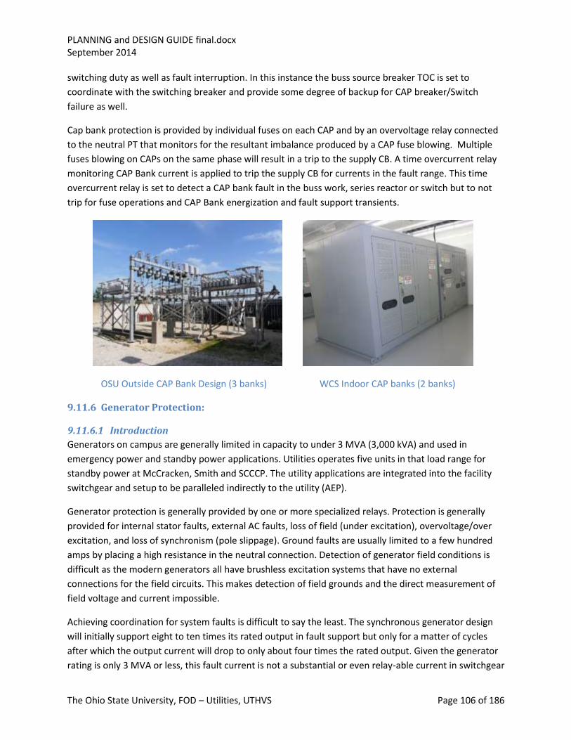
PLANNING and DESIGN GUIDE final.docx September 2014
The Ohio State University, FOD – Utilities, UTHVS Page 106 of 186
switching duty as well as fault interruption. In this instance the buss source breaker TOC is set to
coordinate with the switching breaker and provide some degree of backup for CAP breaker/Switch
failure as well.
Cap bank protection is provided by individual fuses on each CAP and by an overvoltage relay connected
to the neutral PT that monitors for the resultant imbalance produced by a CAP fuse blowing. Multiple
fuses blowing on CAPs on the same phase will result in a trip to the supply CB. A time overcurrent relay
monitoring CAP Bank current is applied to trip the supply CB for currents in the fault range. This time
overcurrent relay is set to detect a CAP bank fault in the buss work, series reactor or switch but to not
trip for fuse operations and CAP Bank energization and fault support transients.
OSU Outside CAP Bank Design (3 banks) WCS Indoor CAP banks (2 banks)
9.11.6 Generator Protection:
9.11.6.1 Introduction
Generators on campus are generally limited in capacity to under 3 MVA (3,000 kVA) and used in
emergency power and standby power applications. Utilities operates five units in that load range for
standby power at McCracken, Smith and SCCCP. The utility applications are integrated into the facility
switchgear and setup to be paralleled indirectly to the utility (AEP).
Generator protection is generally provided by one or more specialized relays. Protection is generally
provided for internal stator faults, external AC faults, loss of field (under excitation), overvoltage/over
excitation, and loss of synchronism (pole slippage). Ground faults are usually limited to a few hundred
amps by placing a high resistance in the neutral connection. Detection of generator field conditions is
difficult as the modern generators all have brushless excitation systems that have no external
connections for the field circuits. This makes detection of field grounds and the direct measurement of
field voltage and current impossible.
Achieving coordination for system faults is difficult to say the least. The synchronous generator design
will initially support eight to ten times its rated output in fault support but only for a matter of cycles
after which the output current will drop to only about four times the rated output. Given the generator
rating is only 3 MVA or less, this fault current is not a substantial or even relay-able current in switchgear

PLANNING and DESIGN GUIDE final.docx September 2014
The Ohio State University, FOD – Utilities, UTHVS Page 107 of 186
rated at 1000 MVA. The situation is even more extreme in the ground fault case where ground faults
are in the range of the larger motor rated loads. It is common practice to avoid even attempting to get
coordination under conditions where the power system is being supplied by the in-house standby or
emergency generation. Instead, the practice is to relay exclusively for the protection of the generator
and the fed system as a whole. This approach might appear unwise at face value, however if you
consider that the need for this generation is based on something else having already failed and hence a
low probability/frequency event, the total impact on system availability is minimal.
9.11.6.2 Phase Faults
Internal faults are addressed by applying a version of the differential protection scheme that is designed
to ride through loading transients and external faults. External faults, which can be only a multiple or
two of normal generator load current, are relayed off by applying a voltage restrained overcurrent relay
which takes advantage of the reduction in terminal voltage that will accompany an external fault.
Sensitivity is taken into account for internal generator faults by not applying the voltage restraint for a
fault fed from an external source via the mains. A second form of current operated protection is the
generator motoring protection which takes the direction of the real component of the generator output.
Should it reverse for any sustained period (seconds), this would be an indication the generator is now
acting as a motor and taking energy from the mains and delivering it to the prime mover. The prime
mover, turbine or internal combustion engine has very limited ability to dissipate heat and can be easily
damaged under these conditions. Generator motoring protection is actually prime mover protection and
deals with relatively small amounts of power in comparison to the output of the generator.
9.11.6.3 Ground faults
Generator grounding is deliberately limited to relatively low fault currents to reduce internal damage to
the generator. An internal ground fault will invariably involve the need for stator iron repair. Large
external ground faults can also result in internal damage to the structure and bracing of the generator
stator. Operating in parallel with a solidly grounded system as we routinely do for surveillance load tests
runs an acknowledged risk of core damage for an internal generator fault, but no additional risk for an
external ground fault.
9.11.6.4 Loss of excitation
Loss of excitation (field) can manifest itself in a variety of ways.
Some generators operating at low speed (salient pole machines) can operate indefinitely with
insufficient excitation so long as there is other healthy generation connected to the mains. Under such
conditions, some generation will run above rated speed and usually end up limited by prime mover
governor action but still generate (induction generation). Neither the overspeed nor the pole slippage
inherent in the induction generation is healthy for the generator and will eventually produce damage to
the stator and rotor. In the case of the low speed machine, excessive reactor swings will produce
overheating in the stator windings, damage to rotor pole faces and rotor damper windings. In the higher
speed round rotor machines (most common), the effect is to induce high AC slip frequency voltages in
the field winding and draw a large reactive current which could overheat the stator. In both cases, since
the excitation is coming from the system, end iron or core damage could also result.

PLANNING and DESIGN GUIDE final.docx September 2014
The Ohio State University, FOD – Utilities, UTHVS Page 108 of 186
If the generator is operating on a weak system or one with no external generation connected, a loss of
field will result in a collapse of the buss load. In addition the generator set may run to over speed unless
the governor is set up to directly detect a loss of power, but unless shutdown, will rapidly return to set
speed and run at no load and virtually no output buss voltage. A common practice is to trip the
generator on loss of buss voltage under these conditions, unless a loss of field relay or loss of excitation
relay trip has been provided.
Loss of field does not meant there will be no detectable generator terminal voltage. As long as the
generator is turning there will be a voltage on the generator terminals. This voltage is caused by residual
flux on the field and is commonly in the three to six hundred volt range making it hazardous to
personnel.
9.11.6.5 Paralleling Out of Phase
There is always a potential for generators to parallel to a live system out of phase. The MG set controls
will usually contain a provision to place a standing trip on the generator breaker when the unit is off.
This is a good feature but not foolproof. A control or mechanical miss-operation of the breaker can still
result in the breaker closing and then tripping free. While this is an insult to the stator and may cause
cumulative damage, it can cause an immediate failure of components in the rotor or field circuit which
will experience a high induced voltage.
Synchronizing (paralleling to an energized buss) is the greatest opportunity for paralleling out of phase.
For this reason it is common practice to apply two devices in the paralleling process, one to control
speed and voltage, then signal breaker closure when phasing is right for paralleling; a second to
supervise the process but monitor relative phase angles and time the period where the starting and
running potentials are within a safe paralleling window (phase angle). The devices should be hardware
independent of each other to avoid common mode failure.
Another situation where there is a risk of paralleling out of phase is a situation where a second source of
voltage is present and there is switching going on involving either make before break load transfers or
switching meant to realign load busses to or from the MG set. A simple switching error can result in
inadvertently paralleling the two sources. The best defense against this is the application of a sync check
function to the close string of the breakers involved. This sync check feature can generally be
incorporated in the multifunction relay applied to providing fault protection to the power circuit or
feeder involved and affords a very effective and low cost solution.
9.11.7 Protection of Low Resistance Grounded Circuits:
By far the most common form of fault on power systems is the phase-to-ground fault. Because of this it
is common practice to limit ground fault magnitudes to a relay-able level but one which will significantly
reduce collateral damage and arc flash levels. Typically, this level is set to the continuous rating of the
feeder or feed breaker, commonly 1,200 to 2,500 Amps for main medium voltage switchgear. This
approach is popular in instances where there are no single phase loads connected phase-to-ground.
Relaying resembles the relaying for phase faults and most often uses the ground elements of the same
multifunction relays as the phase protection as well as the same CT circuits and their residuals.

PLANNING and DESIGN GUIDE final.docx September 2014
The Ohio State University, FOD – Utilities, UTHVS Page 109 of 186
Additional dedicated ground current CT may be applied, particularly in the grounding resistor enclosure
and in donut-configuration in switchgear to detect ground currents.
SCCCP Standby DG Grounding Banks
9.11.8 Protection of Low Voltage Circuits:
Relay protection for low voltage systems (480 or 575 V) is generally provided by the switchgear
manufacturer. They are multifunction relays operating off their own current sensors which are
integrated into an overall protection scheme that may include provisions for arc flash reduction or
improved coordination by including zone interlocking or the use of a maintenance bypass switch.
The relay protection is primarily time overcurrent relaying designed to provide overload protection for
powered equipment and coordination with downstream fuses and circuit breakers. In LV switchgear and
motor control centers, the load protection and first zone of circuit protection is handled by combination
starters or drives that incorporate fault and overload protective functions. They may also contain
protective functions such as single phasing protection and ground fault detection and isolation. Single
phasing is justified; it the power source that incorporates unsupervised fusing. Ground fault detection is
required on solidly grounded systems but not on the high-resistance grounded systems we apply in the
chiller facilities and throughout the power house. Ground fault detectors may however be applied to
individual feeder breakers as an aid to locating a ground in the LV distribution system. These will not be
equipped with a tripping function, however.
Combination starters come in two common configurations: with fused disconnects, and equipped with a
molded case breaker with a thermal or thermo magnetic element provided to trip the breaker for a
substantial fault current. The advantage of the fused disconnect over the molded case breaker is the
significantly faster fault clearing for a phase fault and the resultant reduction in residual damage and arc
flash. It also supports better fault coordination and provides a shorter overall system delay for clearing
faults anywhere in the system. The detraction is that it is a potential source of single phasing. The
molded case breaker approach addresses the single phasing concern but introduces a trip delay not
inherent in the equivalent fuse application. In instances where there is a viable PM program which
includes breaker testing, the preferred approach would be to use molded case breakers. If arc flash
exposure is a critical consideration, fused disconnects may prove a better solution.

PLANNING and DESIGN GUIDE final.docx September 2014
The Ohio State University, FOD – Utilities, UTHVS Page 110 of 186
9.12 Fusing Strategies
9.12.1 Component protection vs. system protection
The protection philosophy described above as applied to the MV system power components also applies
to lower voltage power and control components. Control circuits are an application where fusing to
protect components and wiring from overloading is common and a frequent cause of miss-operation.
Fusing should be applied to provide fault isolation and coordination/selectivity, not to protect
components from being overloaded. The practice of fusing to conform to control wiring or power wiring
thermal rating for that matter is equally problematic and unnecessary in an engineered design where
accidental overloading is not an issue. If wire gauge is inadequate to manage reasonable fault levels,
then the wire gauge needs to be corrected. On the flip side, selecting wire gauge based on source
breaker rating in a non NEC application is inefficient at the least, and counterproductive , particularly in
an engineered design or where the source breaker is used only as a disconnect point.
9.12.2 Coordination and selectivity
Coordination and selectivity concerns apply equally to MV circuits and to low voltage power and control
circuits. The objective is to isolate a faulted component with a minimum disruption to other components
and circuits. This is accomplished through coordination of tripping values and tripping time delays
(coordination) so that only the faulted devices and circuit components associated with them are
disconnected from power (selectivity). In some instances, selectivity can take on additional dimensions
as is the case with switchgear control and switchgear metering circuits where a preference can be
assigned to the decision of what trips and what remains energized based on its function in the circuit
(e.g. tripping takes precedence over charging and closing).
Primary service fusing strategy deserves some special consideration. It has evolved over the years with
the introduction of new technologies.
In the past, the dual primary service was provided to the campus buildings from a primary select switch
with two incoming air break switches and a common buss and load side fuse compartment. This
configuration provided the necessary visible break and fuse-isolation for a faulted transformer and load
way. The introduction of multiple load ways (double ended substations or load aggregation) was
accommodated by providing additional load break switches ahead of the respective transformer fuses
allowing for separate isolation of individual transformers. The relay settings in the feeder protection at
the substation was set to coordinate with the transformer fuse characteristics and provide fast clearing
of a faulted feeder.
At one point in the recent past, the campus switched technologies and started substituting SF6 gas
insulated primary switches with RFI (Resettable Fault Interrupters) in the load way(s). The intent was to
replace the high maintenance air break design with low maintenance technology and do away with the
exposure of having in-line fuses. This design approach had two flaws: The RFI afforded no visible break
in instances where there were more than one load way served by the switch, and the RFI, which is a
form of circuit breaker, and had a longer total clearing time than the fuse it replaced, resulting in

PLANNING and DESIGN GUIDE final.docx September 2014
The Ohio State University, FOD – Utilities, UTHVS Page 111 of 186
coordination issues with the main feeder breaker in the substation. To rectify these deficiencies some
services were fitted with a compact three phase ganged fused switch.
In our current design, our standard configuration is an SF6 gas insulated primary select switch with RFI
protected load way(s) feeding into a primary fused disconnect switch mounted adjacent to the primary
service transformer. In this configuration, the fuse protects for a transformer failure affording rapid
clearing and limiting the potential for fire damage or explosion, the primary disconnect switch provides
the visible isolation required, the RFI is set a bit slower than the fuse and provides some level of arc flash
reduction for the switchman on the transformer primary disconnect and also on switching the
transformer secondary, and the SF6 gas switch does the load switching and feeder selection. This
arrangement is common on unit substations, single and double ended where the transformer’s inside
the building.
Some applications have liquid-filled transformers exterior to the building. In these cases an alternative
design may be applied where the load way is supplied via an RFI or SF6 switch and a fused load break
elbow is placed at the transformer primary or at the primary select switch to provide the fusing
required. This design approach has limitations and some variants. The fused load break technology does
not exist for applications greater than 1,500 kVA. In instances where the primary select is an existing
switch and the load way has an RFI, we have allowed pulling of the load break (three single phase
connections not ganged) to establish the visible break. This is not a preferred design because it involves
a greater level of personnel exposure and is a phase-by-phase operation with some inherent risk of
single phasing the building loads. In instances where larger than 1,500 kVA transformers are involved
(fuses > 80E) we revert to the separate compact ganged fused disconnect design preferably supplied
from an RFI, though a gas load break is acceptable.
9.13 Low Voltage AC Distribution
9.13.1 Introduction
AC distribution below 1000 VAC is classified as low voltage. In main campus central chiller, power plant
and substation facilities this includes 480 v, 575 v, 120/208 v and 120/240 v distributions.
In general, while we try to comply with the requirements of the NEC, the engineered aspect of most of
our systems and the training level of our maintenance personnel along with our safety procedures,
dictate that we depart from the NEC in many instances.
The design of main campus central chiller and power plant systems is governed by the requirements of
the BDS DIV 48 (draft) and the main substations by the BDS DIV 33.
9.13.2 Auxiliary power distribution
The main low voltage distributions are at 480 VAC and for the newer central chiller plants at 575 VAC.
These are designed around a double-ended substation design. LV buss alignment reflects the power
supply separation and redundancy engineered into the MV system to limit the impact of equipment
failures and outages on the availability of plant capacity.
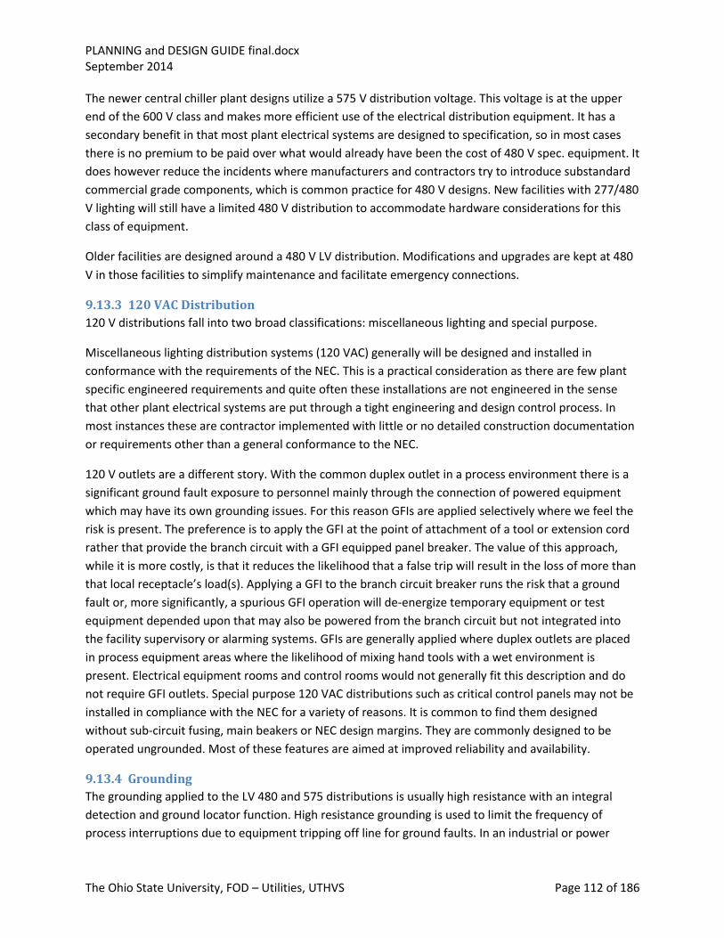
PLANNING and DESIGN GUIDE final.docx September 2014
The Ohio State University, FOD – Utilities, UTHVS Page 112 of 186
The newer central chiller plant designs utilize a 575 V distribution voltage. This voltage is at the upper
end of the 600 V class and makes more efficient use of the electrical distribution equipment. It has a
secondary benefit in that most plant electrical systems are designed to specification, so in most cases
there is no premium to be paid over what would already have been the cost of 480 V spec. equipment. It
does however reduce the incidents where manufacturers and contractors try to introduce substandard
commercial grade components, which is common practice for 480 V designs. New facilities with 277/480
V lighting will still have a limited 480 V distribution to accommodate hardware considerations for this
class of equipment.
Older facilities are designed around a 480 V LV distribution. Modifications and upgrades are kept at 480
V in those facilities to simplify maintenance and facilitate emergency connections.
9.13.3 120 VAC Distribution
120 V distributions fall into two broad classifications: miscellaneous lighting and special purpose.
Miscellaneous lighting distribution systems (120 VAC) generally will be designed and installed in
conformance with the requirements of the NEC. This is a practical consideration as there are few plant
specific engineered requirements and quite often these installations are not engineered in the sense
that other plant electrical systems are put through a tight engineering and design control process. In
most instances these are contractor implemented with little or no detailed construction documentation
or requirements other than a general conformance to the NEC.
120 V outlets are a different story. With the common duplex outlet in a process environment there is a
significant ground fault exposure to personnel mainly through the connection of powered equipment
which may have its own grounding issues. For this reason GFIs are applied selectively where we feel the
risk is present. The preference is to apply the GFI at the point of attachment of a tool or extension cord
rather that provide the branch circuit with a GFI equipped panel breaker. The value of this approach,
while it is more costly, is that it reduces the likelihood that a false trip will result in the loss of more than
that local receptacle’s load(s). Applying a GFI to the branch circuit breaker runs the risk that a ground
fault or, more significantly, a spurious GFI operation will de-energize temporary equipment or test
equipment depended upon that may also be powered from the branch circuit but not integrated into
the facility supervisory or alarming systems. GFIs are generally applied where duplex outlets are placed
in process equipment areas where the likelihood of mixing hand tools with a wet environment is
present. Electrical equipment rooms and control rooms would not generally fit this description and do
not require GFI outlets. Special purpose 120 VAC distributions such as critical control panels may not be
installed in compliance with the NEC for a variety of reasons. It is common to find them designed
without sub-circuit fusing, main beakers or NEC design margins. They are commonly designed to be
operated ungrounded. Most of these features are aimed at improved reliability and availability.
9.13.4 Grounding
The grounding applied to the LV 480 and 575 distributions is usually high resistance with an integral
detection and ground locator function. High resistance grounding is used to limit the frequency of
process interruptions due to equipment tripping off line for ground faults. In an industrial or power
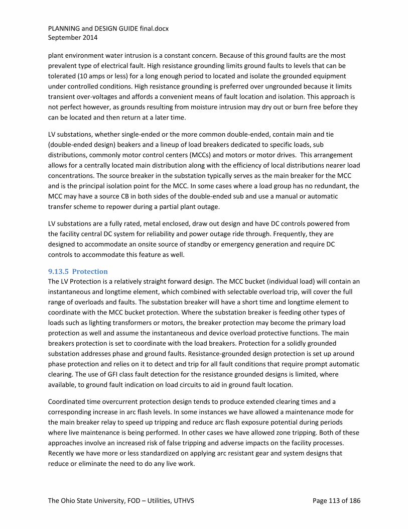
PLANNING and DESIGN GUIDE final.docx September 2014
The Ohio State University, FOD – Utilities, UTHVS Page 113 of 186
plant environment water intrusion is a constant concern. Because of this ground faults are the most
prevalent type of electrical fault. High resistance grounding limits ground faults to levels that can be
tolerated (10 amps or less) for a long enough period to located and isolate the grounded equipment
under controlled conditions. High resistance grounding is preferred over ungrounded because it limits
transient over-voltages and affords a convenient means of fault location and isolation. This approach is
not perfect however, as grounds resulting from moisture intrusion may dry out or burn free before they
can be located and then return at a later time.
LV substations, whether single-ended or the more common double-ended, contain main and tie
(double-ended design) beakers and a lineup of load breakers dedicated to specific loads, sub
distributions, commonly motor control centers (MCCs) and motors or motor drives. This arrangement
allows for a centrally located main distribution along with the efficiency of local distributions nearer load
concentrations. The source breaker in the substation typically serves as the main breaker for the MCC
and is the principal isolation point for the MCC. In some cases where a load group has no redundant, the
MCC may have a source CB in both sides of the double-ended sub and use a manual or automatic
transfer scheme to repower during a partial plant outage.
LV substations are a fully rated, metal enclosed, draw out design and have DC controls powered from
the facility central DC system for reliability and power outage ride through. Frequently, they are
designed to accommodate an onsite source of standby or emergency generation and require DC
controls to accommodate this feature as well.
9.13.5 Protection
The LV Protection is a relatively straight forward design. The MCC bucket (individual load) will contain an
instantaneous and longtime element, which combined with selectable overload trip, will cover the full
range of overloads and faults. The substation breaker will have a short time and longtime element to
coordinate with the MCC bucket protection. Where the substation breaker is feeding other types of
loads such as lighting transformers or motors, the breaker protection may become the primary load
protection as well and assume the instantaneous and device overload protective functions. The main
breakers protection is set to coordinate with the load breakers. Protection for a solidly grounded
substation addresses phase and ground faults. Resistance-grounded design protection is set up around
phase protection and relies on it to detect and trip for all fault conditions that require prompt automatic
clearing. The use of GFI class fault detection for the resistance grounded designs is limited, where
available, to ground fault indication on load circuits to aid in ground fault location.
Coordinated time overcurrent protection design tends to produce extended clearing times and a
corresponding increase in arc flash levels. In some instances we have allowed a maintenance mode for
the main breaker relay to speed up tripping and reduce arc flash exposure potential during periods
where live maintenance is being performed. In other cases we have allowed zone tripping. Both of these
approaches involve an increased risk of false tripping and adverse impacts on the facility processes.
Recently we have more or less standardized on applying arc resistant gear and system designs that
reduce or eliminate the need to do any live work.

PLANNING and DESIGN GUIDE final.docx September 2014
The Ohio State University, FOD – Utilities, UTHVS Page 114 of 186
9.13.6 Annunciation and Condition Monitoring
Only main substations have central annunciator systems. Central chilled plants and the power plant
monitoring and alarming functions are performed by the DCS systems which provide the level of
supervision appropriate for an unmanned facility. With this approach, process monitoring is relatively
thorough. Monitoring of auxiliary systems tends to be spotty and focused at a key component or overall
system level at best. Metering in central facilities takes on a variety of forms. Energy metering is
generally performed at central supply points where power enters the low voltage distribution systems
(480 V and 575 V AC) at the secondary main side of the facility unit substations. This metering is used to
help in determining production costs. Individual drives may have energy metering installed for the
purpose of evaluating drive efficiency such as is done for chiller packages. Some metering may be
present within the MV distribution system such as the 13 kV and 5 kV switchgear for remote monitoring
of feeder loading, buss potential and critical circuit breaker position. As a point of policy we require that
all these meters meet BDS requirements for functionality and connectivity. The choice of metering
points and the choice of mounting locations are design specific.
9.14 Grounding Systems The main campus 13.2 kV distribution system is operated as a solidly grounded system. The sources of
power to the system are the six main 138 kV transformers located at OSU and WCS substations. Their
secondary windings are Y-connected with the neutral point of the Ys tied to their substation ground
mats. All 13.2 kV distribution circuits are likewise tied back to these substation ground mats through a
network of 4/0 ground cables run one with each feeder circuit. In addition to this substation grounding,
the distribution circuits have this ground conductor grounded at the primary services as well as at
various points along the course of the feeder run at manholes and splicing points. Unlike the grounding
at the load points on the MV distribution system which involves multiple grounding points, the MV
power source grounding is at the source substation from one location: the neutrals of the 138 kV
transformer secondary winding neutrals. These are the ground reference for the MV system voltage and
the return points for ground faults. If a portion of the MV distribution system is operated independent
of its normal AEP utility source as is the case for portions of the Smith substation and for the SCCCP
when on DG standby power, a suitable ground reference for the MV system must be established. When
on DG, the generators which are Y-connected machines have a neutral grounding resistor that, while
limited to a few hundred amps, will supply this ground reference. At Smith, where the DG supplying
standby power is connected to the 5 kV buss, and back feeding onto the station 15 kV, there is no source
grounding reference necessitating the addition of a grounding bank. In the case of busses 401 and 601
at Smith the grounding bank is a zig-zag transformer connected to the primary sides of the Smith 13.2 to
5 kV transformers. An alternative would have been to apply a two winding grounding bank. Refer to the
IEEE standards and guides for more information on the connection and ratings for this class of
equipment.
9.14.1 MV Power System Grounding
Power grounding is provided to insure a high quality low resistance path for fault current to return to
the substation source. It is designed to common up all 4/0 ground leads long with shield drains and local
grounding provisions and provide a path for shield drain currents, surge suppression and capacitive

PLANNING and DESIGN GUIDE final.docx September 2014
The Ohio State University, FOD – Utilities, UTHVS Page 115 of 186
current unbalances to find ground. Connections are generally copper-bolted connections designed for
disassembly for test and maintenance without cutting or brazing. Ground fault currents follow the path
of least impedance back to the substation source, In the case of AC this turns out to be the path taken
by the circuit itself. Having ground conductors run with the circuit phase conductors in the same conduit
further facilitates achieving this ground path and reduces the effects caused by stray ground currents
during a ground fault. In power operation, the only current flowing through ground and these ground
conductors is the current from stray capacitive loadings on the power cables and drain currents present
in the cable shields caused by stray magnetic flux from the load conductors. Typically these currents are
in the range of 5 to 10 amps. The primary distribution system is a grounded system, however we restrict
primary transformers to three phase delta connected high voltage windings. This forces all load currents
to be in the phases and not invade the grounding system and allows the use of 4/0 insulated cable. The
cable insulation level is 600 V and the insulation is needed to insure that the cable will be grounded at
only the points desired. Inadvertent grounding can cause arcing during ground fault events and the
possibility of cable damage or fire. In contrast to an overhead distribution where the phase conductors
are air insulated and placed a fair distance apart, having the power cables in one conduit along with the
ground return cable greatly reduces the effects of stray ground currents and radiated emissions as well.
It is common to see single phase loads powered from overhead systems. This practice greatly increases
the potential for radiated emissions and radio frequency interference (RFI). On the campus MV
distribution system, single phase loads on the secondary side of the primary transformers transforms to
phase-to-phase on the MV side, with about the same radiative effect as a balanced three phase load.
Radiated emissions for a buried balanced three phase system such as we have on campus is much lower
than for an overhead system for a range of reasons: phase conductor spacing, balanced loading,
shielding, and careful attention to ground return path.
9.14.2 Safety Grounding
Safety grounding, or equipment-cabinet grounding, is provided to insure that touch or step potential is
within safe limits in and around the MV and low voltage electrical equipment. It is most obvious on the
MV system at switches and in the substation with the grounding of switch enclosures, structures and
station fencing. The object in this form of grounding is to insure that the individual will not bridge by
step or touch any significant voltage differences or bridge a significant voltage gradient. Pad-mounted
switches are installed with a ground ring buried in the surrounding soil that is brought back to the switch
enclosure and bonded or bolted to the enclosure and local building or earth grounding system. Fence
grounding for touch or step potential is done in a similar fashion with attachments to the station ground
grid at regular intervals, and a buried portion running three or more feet outside of the fence line. As a
further protection some areas of the substation will be outfitted with step-off pads and grids, typically at
gates or at control stations near equipment to be operated. These pads are bonded to the ground grid
and local steel to decrease the risk of bridging local potential gradients during system fault conditions.
The BDS requires multiple grounding for electrical equipment. This grounding system calls for two
independent paths to local ground. The object is to insure that an inadvertent loosening or corrosion of
a single ground path will not in and of itself result in electrical equipment not being effectively
grounded. In an industrial environment or in an environment where grounding is not easily inspected,

PLANNING and DESIGN GUIDE final.docx September 2014
The Ohio State University, FOD – Utilities, UTHVS Page 116 of 186
initially providing multiple paths greatly reduces the likelihood of equipment eventually posing a touch
potential hazard.
9.14.3 Lightning Protection
Electrical substations and any exposed electrical equipment are normally afforded some form of
lightning protection. Main substations have grounding systems comprised of poles and ballast wires.
These are one of the most obvious features at WCS. They afford a high degree of protection against
lightning damage for all the equipment under what is commonly referred to as a 30 Deg. cone of
protection. Outside of this cone of protection, supplemental grounding systems employing their own
towers and ground rods are applied. These may resemble the lightning rods present on other campus
facilities. Lightning protection relies on a solid connection to local ground to be effective. Where this is
not the case, Lightning protection can actually introduce lightning effects into sensitive areas on a
facility. Fortunately for us, grounding on campus is far from difficult with no shortage of excellent
grounding structures, a high water table and a relatively wet year round environment.
9.14.4 Instrument Grounds
PT ground connections are significant to voltage measurement accuracy and also phase angle
comparisons in some applications. Current transformer grounding is likewise significant to the
functioning of a protection circuit both from a trip current consideration and also from a personnel
safety perspective. Their close proximity to energized buss work and their ability to generate extremely
high voltages when open circuited under load present risk of exposure to personnel.
Sensitive electronics requires special handling with respect to ground for reliable operation.
Recommended practice (IEEE and ISA) would have all instrument grounds isolated from chassis and
equipment grounds and brought to a common point of connections at plant ground. The logic behind
this practice is that there is an overriding need to avoid grounding conditions where ground loops are
set up and can induce noise, errors and bias in sensitive instrument connections. In most cases where
the path to ground is relatively short (a few hundred feet), this practice is generally effective. Much
beyond that distance other considerations become a concern. Higher frequencies of plant-generated
electrical noise such as inverters, variable speed drives and in some case switching electromagnetics can
become the main source of interference. Long, single-lead ground paths are ineffective at shunting of
such electrical noise requiring a more sophisticated approach. Instrument grounds or what is described
as “high quality” grounds should be reserved for the signal portion of the controls not chassis grounds or
power grounds. Shield connections and instrument ground references are normally what are connected
in practice. The ground wire needs to be insulated from ground along its entire length and of a relative
large gauge (600 V, 4/0 copper cable is typically the preferred choice). The insulation is to avoid the
creation of inadvertent ground loops in the run and the gauge is required to reduce the AC reactance of
the run for draining off electrical noise in the higher frequency ranges.
9.15 Switchgear Control MV and LV metal enclosed switchgear is available with a range of control options that include both DC
and AC control. The gear, a customer specification-driven product, will also be delivered with a portion
of the breaker not constrained by the manufacturer’s mechanism design available for customization to

PLANNING and DESIGN GUIDE final.docx September 2014
The Ohio State University, FOD – Utilities, UTHVS Page 117 of 186
the customer’s preferences. Of the two classes, the MV gear is more amenable to customer’s
preferences due to the fact that its hardware is less wedded to a particular manufacturers current
sensing and trip devices.
9.15.1 Choice of Control voltage
Aside from the control voltage level, there is usually a choice to be made between AC and DC control.
The advantage of AC control is that is does not require the availability of a central battery system. It
does have its drawbacks however. AC control requires some care be taken in the location of the
associated CPTs. Where normally CPTs would be powered off the main switchgear buss and used for
metering and relaying as well in some applications, the CPT in an AC control line-up would have to be
placed on the line side of the incoming breaker to obtain control power to close the main and energize
the buss work. This can get complicated when working with a double-ended substation design. There
are workarounds possible. Tripping poses a more knotty issue. AC control generally requires the
inclusion of a capacitor trip to all the breakers in the lineup. Capacitor trips involve the use of a stored
energy electrical device. Stability of charge and age of the device become an issue. AC control is fairly
common in LV switchgear and in applications where the user has limited ability to support a central DC
battery control system; it may be the better solution. AC control is less common in MV switchgear and
fault current powered or capacitor tripping systems are less common and, where present, offer fewer
options for protective features. If a DC central battery system is available, AC control should be avoided
when designing and installing LV and MV switchgear.
DC control for both MV and LV switchgear is preferred. The DC control voltage should be no lower than
100 volts, with 125 VDC nominal our current reference design. Control voltages lower than 48 volts are
problematic in control where the relay and device contact structures and contact surfaces cannot be
closely controlled. Also, industrial environments such as are present at McCracken PP and to some
extent at OSU and Smith Sub pose a challenge to exposed contact designs such as found in switchgear
auxiliary switches and industrial relays and control switches. Specifying 125 VDC provides a safe margin
against encountering contact reliability issues during the life of the equipment.
There are a variety of design approaches to supplying a switchgear line-up with DC control power. The
most common is to bring a single source of DC from a DC panel into the gear and distributing it breaker
compartment to breaker compartment. Another common method is to supply each breaker
compartment with its own DC branch circuit. Both of these approaches have advantages and drawbacks.
A single supply circuit design may result in the simultaneous loss of both individual feeder control power
and main power. Individual branch circuit designs makes wholesale loss of DC less likely but make
monitoring of the availability of DC control more difficult and costly. It also invites confusion as to where
to take LOTO and increases the likelihood of a control circuit protective malfunction. With the common
DC feed, the possibility of the unintentional loss of DC to other breakers in a line-up is increased while
doing unrelated maintenance in an adjacent breaker compartment. While we have examples of both of
these approaches in switchgear on campus, our preferred design is one where a single large capacity DC
feed is brought into the switchgear line-up and run through the gear and then looped back to the point
of entry. Each breaker and every protective not unique to an individual CB is fused separately off this

PLANNING and DESIGN GUIDE final.docx September 2014
The Ohio State University, FOD – Utilities, UTHVS Page 118 of 186
main DC loop. Servicing an individual cubical, in this configuration will not run the risk of inadvertently
de-energizing other breakers controls. It is also very unlikely that a larger main DC breaker or fuse will
miss-operate during breaker operations.
Typical Switchgear Breaker Control circuit Schematic
9.15.2 Reference DC control model
The figure above shows our preferred control schematic for 125 VDC control of MV switchgear. The
schematic infers a source of DC either looped or dedicated branch circuit. Of interest in the circuit is the
treatment of the close and trip circuits, powering of the spring charging motor and powering of the
protective relays and meters. Incoming DC passes through a CB main fuse block that serves both as a
disconnect point for all CB control power as well as fault isolation for a fault in the CB DC wiring. This is a
dual fuse block that contains two fuses sized to coordinate with the DC source fuse or breaker.
The DC circuit on the load side of this fuse block serves as power source for all breaker controls and
associated CB associated devices including the CB trip circuit, protective relays, and CB metering when
provided. It also serves as the supply to a sub-fused control buss that supplies the close circuit and
spring charging motor. The sub-fusing is selected to coordinate with the CB main fuse block. The meter
is also sub-fused off the main fuse. Note: We do not sub-fuse the protective relay.
This circuit arrangement is chosen to give preference to CB tripping over closing, insuring a spring
charging motor failure does not inhibit tripping, and insuring CB supervisory features generally provided

PLANNING and DESIGN GUIDE final.docx September 2014
The Ohio State University, FOD – Utilities, UTHVS Page 119 of 186
through the CB meter continue to function for a CB that trips regardless of the condition of the close
circuit and spring charging circuits. Sub-fusing the meter insures that a meter failure will not cause the
loss of tripping capability for the CB. Not fusing the protective relay is to remove one failure point in the
CB trip circuit that could result in failure of the CB to trip when required to.
MV switchgear should be specified with the maximum number of MOC and stationary aux switches. Cell
switches (TOC) should also be specified in instances where interlocks are present and there is a need to
differentiate between the CB in test and inserted.
Always err on the high side when specifying MOC, aux and cell switches. The use of auxiliary relays to
communicate breaker position is a risky design approach and should be avoided if at all possible. CBs are
bi-stable devices that do not require power to maintain their position, relays do which can result in
giving the wrong information about CB position to interlocked equipment and systems if the relay fails
or its DC control buss is de-energized.
Breaker position is given by providing indicator lights on the switchgear door (metering compartment in
one high designs); red for CB closed, green for CB open. The open indication is above and to the left of
the CB control switch. The closed indication is above and to the right of the CB control switch. The
closed indication serves a dual purpose; CB position indication and an indication of trip circuit continuity.
Most switchgear is provided with an anti-pump feature designed into the close circuit. This feature is
designed to insure that if the CB were to close into a fault the breaker would trip free and not reclose
into the fault a second time. For this feature to work, it is important for the close string of the breaker to
be maintained energized throughout the close and trip free action. In manual close and trip operations,
this can be managed by specifying a control switch that has a contact in the close string, that is closed in
the “close” or “close” and also “after close” positions of the switch (this is referred to as a slip contact).
Allowing the close string to open and reclose at any time in the close and trip free cycle will defeat the
trip free feature and allow the CB to reclose. If the correct control switch is applied, inadvertent
reclosure would only be an issue under manual control, or if there are interlocks present in the close
string that may open when the CB closes. CBs with an automatic close feature pose a greater risk. In
such instances it is best to design the trip circuit with a manually resettable lock-out device that places a
standing trip on the CB and at the same time opens the close string blocking any subsequent close
signal.
9.15.3 Reference AC control and Protection model
Most of the circuit details listed for the DC control version also apply to the AC control version,
particularly the preference for trip over close. The close circuit on an AC controlled CB is similar to the
DC controlled version, however the trip circuit is considerably more complex and more manufacturer
specific as it involves the application of some form of capacitor tripping device.
9.16 Motor Control Motor control centers are used to provide an efficient centralized point from which to power smaller
drives. The basic building block is what is referred to as a combination starter. The combination starter
contains an incoming isolation and fault elimination device (molded case circuit breaker or fused

PLANNING and DESIGN GUIDE final.docx September 2014
The Ohio State University, FOD – Utilities, UTHVS Page 120 of 186
disconnect), a single phase control transformer, a starter and overload tripping device frequently
integral with the starter and control power fuses. Depending on the application and protection
requirement, other features may be included. The starter is a magnetically held device that will drop out
on loss of power. Opening the circuit breaker or fused disconnect will turn power off to the control
power transformer and starter. The overload is wired to interrupt control power to the starter in the
event an overload is detected. The overload device requires manual resetting and generally is wired to
remove control power from not only the starter but also the indication. Fault detection and tripping is
performed by the molded case CB or the fuses in the fused disconnect. The starter is not designed to
interrupt fault current, only starting and running current. Some small motor drives have integral
overload devices provided to drop out the starter for a motor overload condition. These should not be
wired into the starter control circuit as their operation can be confused with the starter overload which
is not self-resetting. These devices typically self-reset with the potential for unexpectedly restarting the
drive and posing a risk to equipment and maintenance personnel.
Some motors are provided with a disconnect local to the powered equipment. In most non-utility
applications this is a code requirement. In utility facilities, we rely on LOTO procedures and training to
provide a safe work environment. The addition of a local disconnect represents one additional failure
point one that is generally located in a relatively hostile environment. However, in instances where the
MCC starter is inaccessible or inconvenient to access we design-in a local disconnect. This disconnect
must be rated to interrupt load current and be equipped with a position switch which opens ahead of
the switch mains and is wired to de-energize the motor starter contactor. In the normal course of
events, the operator will LOTO the MCC, then open and LOTO the disconnect prior to starting work on
the motor and driven equipment. For subsequent work periods, the requirement to verify LOTO can be
limited to verifying LOTO on the disconnect. At the completion of work, the MCC starter LOTO must be
verified, then the disconnect may have its LOTO removed and the switch closed. The final step has the
LOTO removed on the MCC starter. In most applications we do not design in a local disconnect.
Experience indicates that they are commonly abused by nonelectrical personnel seeking to isolate a
drive. Without the proper training, a decision to open a local disconnect can expose the operator to arc
flash hazards or worse. Opening a non-load break switch under load or a load break under fault
conditions can result in an explosion and fire.
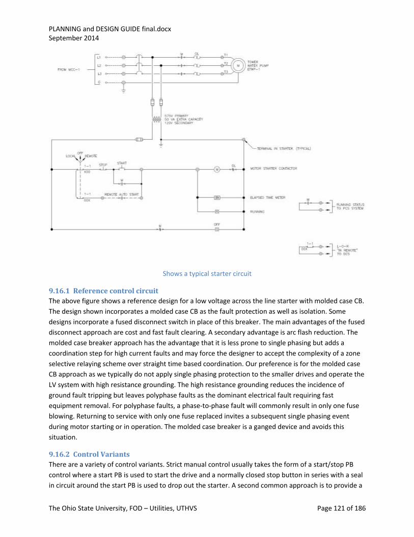
PLANNING and DESIGN GUIDE final.docx September 2014
The Ohio State University, FOD – Utilities, UTHVS Page 121 of 186
Shows a typical starter circuit
9.16.1 Reference control circuit
The above figure shows a reference design for a low voltage across the line starter with molded case CB.
The design shown incorporates a molded case CB as the fault protection as well as isolation. Some
designs incorporate a fused disconnect switch in place of this breaker. The main advantages of the fused
disconnect approach are cost and fast fault clearing. A secondary advantage is arc flash reduction. The
molded case breaker approach has the advantage that it is less prone to single phasing but adds a
coordination step for high current faults and may force the designer to accept the complexity of a zone
selective relaying scheme over straight time based coordination. Our preference is for the molded case
CB approach as we typically do not apply single phasing protection to the smaller drives and operate the
LV system with high resistance grounding. The high resistance grounding reduces the incidence of
ground fault tripping but leaves polyphase faults as the dominant electrical fault requiring fast
equipment removal. For polyphase faults, a phase-to-phase fault will commonly result in only one fuse
blowing. Returning to service with only one fuse replaced invites a subsequent single phasing event
during motor starting or in operation. The molded case breaker is a ganged device and avoids this
situation.
9.16.2 Control Variants
There are a variety of control variants. Strict manual control usually takes the form of a start/stop PB
control where a start PB is used to start the drive and a normally closed stop button in series with a seal
in circuit around the start PB is used to drop out the starter. A second common approach is to provide a

PLANNING and DESIGN GUIDE final.docx September 2014
The Ohio State University, FOD – Utilities, UTHVS Page 122 of 186
two position switch (Off/Run) to pick up the starter. The former approach has the imbedded feature
that it will require operator involvement to restart the motor after a power outage. With the latter
approach, the motor will restart automatically on power restoration. Standard bucket wiring can be
specified to provide accommodation for both variants, and these controls may be placed on the door of
the bucket or remote from the MCC. Remote from the MCC requires the bucket wiring to bring a limited
number of control wires to a customer interface terminal block, as would any provisions for remote
indication or interlocking.
Automatic control usually involves external wiring out to a separate control system, or remote process
instrument such as a pressure switch, thermostat or level switch. This also requires the bucket wiring to
bring a limited number of control wires to a customer interface terminal block. When automatic controls
are applied it is customary to provide a local (to the MCC) override or lockout switch on the bucket door
and a running indication as well.
Safety interlocking, such as vibration switches and local disconnect interlocking, is wired into the starter
control string after the auto/run switch and before the contactor to insure that once operated neither
the remote start nor the manual controls can turn the drive on. It is common practice for interlocks such
as vibration trips to add a seal in lockout relay ahead of the control string, that will keep the drive locked
out until the starter’s main beaker or fused disconnect is opened.
There are two variants for running indication. In most cases a simple red running indication is sufficient.
In some cases particularly in cases where it important to know whether the motor overload has tripped
or the drive is simply not being required to run, a red/green indication scheme similar to what is applied
to CBs is required. If the overload has tripped both red and green lights will be out. If the drive is
stopped and the green light is on, the controls are not requesting a start.
9.16.3 Wiring and Cabling Standards
OSU Utilities wiring standards compliance is required on all motor control equipment purchased to
specification. These requirements are given in the BDS DIVs 33 and 48 and relate to wire type, labeling,
termination and equipment layout and wire harnessing. The choice of wire type is important for a
variety of reasons including tolerance to vibration, insulation service life and fire retardancy. Labeling,
layout and harnessing is important for maintenance and troubleshooting reasons. Terminations are
important for operating reliability as well as access for troubleshooting.
9.17 Motors
9.17.1 Introduction
Motor application, primarily in the power plant and central chiller (production) facilities, is a lot more
severe than in most commercial applications. The consequence of motor failure tends to be more
significant as well. For this reason, we tend to specify motors with more design margin, longer operating
life and improved constructability/maintainability. The motor applications we have tend to be 24/7 and
at higher ambient temperatures frequently above 30°C. For these applications special attention needs to
be paid to insulation systems, motor housings, bearings and connection terminal boxes.
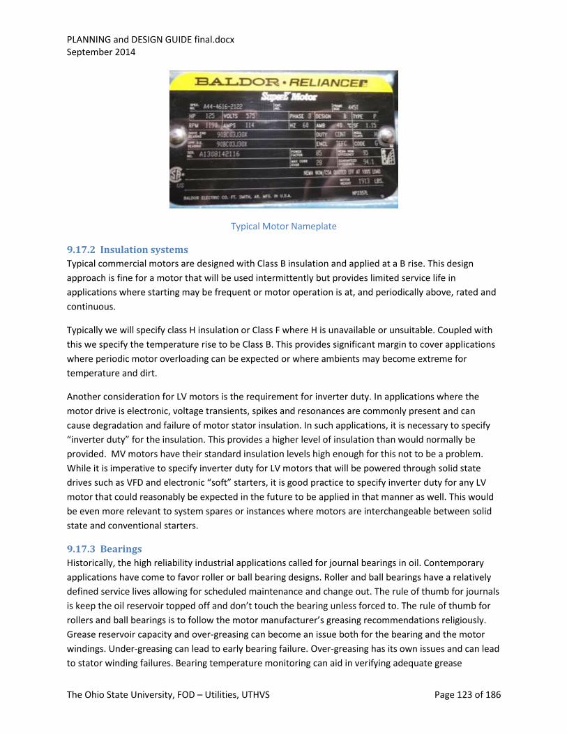
PLANNING and DESIGN GUIDE final.docx September 2014
The Ohio State University, FOD – Utilities, UTHVS Page 123 of 186
Typical Motor Nameplate
9.17.2 Insulation systems
Typical commercial motors are designed with Class B insulation and applied at a B rise. This design
approach is fine for a motor that will be used intermittently but provides limited service life in
applications where starting may be frequent or motor operation is at, and periodically above, rated and
continuous.
Typically we will specify class H insulation or Class F where H is unavailable or unsuitable. Coupled with
this we specify the temperature rise to be Class B. This provides significant margin to cover applications
where periodic motor overloading can be expected or where ambients may become extreme for
temperature and dirt.
Another consideration for LV motors is the requirement for inverter duty. In applications where the
motor drive is electronic, voltage transients, spikes and resonances are commonly present and can
cause degradation and failure of motor stator insulation. In such applications, it is necessary to specify
“inverter duty” for the insulation. This provides a higher level of insulation than would normally be
provided. MV motors have their standard insulation levels high enough for this not to be a problem.
While it is imperative to specify inverter duty for LV motors that will be powered through solid state
drives such as VFD and electronic “soft” starters, it is good practice to specify inverter duty for any LV
motor that could reasonably be expected in the future to be applied in that manner as well. This would
be even more relevant to system spares or instances where motors are interchangeable between solid
state and conventional starters.
9.17.3 Bearings
Historically, the high reliability industrial applications called for journal bearings in oil. Contemporary
applications have come to favor roller or ball bearing designs. Roller and ball bearings have a relatively
defined service lives allowing for scheduled maintenance and change out. The rule of thumb for journals
is keep the oil reservoir topped off and don’t touch the bearing unless forced to. The rule of thumb for
rollers and ball bearings is to follow the motor manufacturer’s greasing recommendations religiously.
Grease reservoir capacity and over-greasing can become an issue both for the bearing and the motor
windings. Under-greasing can lead to early bearing failure. Over-greasing has its own issues and can lead
to stator winding failures. Bearing temperature monitoring can aid in verifying adequate grease
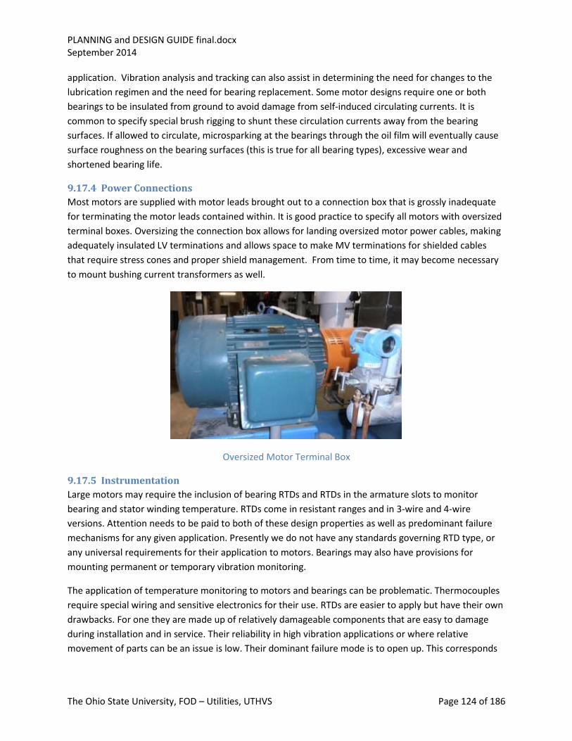
PLANNING and DESIGN GUIDE final.docx September 2014
The Ohio State University, FOD – Utilities, UTHVS Page 124 of 186
application. Vibration analysis and tracking can also assist in determining the need for changes to the
lubrication regimen and the need for bearing replacement. Some motor designs require one or both
bearings to be insulated from ground to avoid damage from self-induced circulating currents. It is
common to specify special brush rigging to shunt these circulation currents away from the bearing
surfaces. If allowed to circulate, microsparking at the bearings through the oil film will eventually cause
surface roughness on the bearing surfaces (this is true for all bearing types), excessive wear and
shortened bearing life.
9.17.4 Power Connections
Most motors are supplied with motor leads brought out to a connection box that is grossly inadequate
for terminating the motor leads contained within. It is good practice to specify all motors with oversized
terminal boxes. Oversizing the connection box allows for landing oversized motor power cables, making
adequately insulated LV terminations and allows space to make MV terminations for shielded cables
that require stress cones and proper shield management. From time to time, it may become necessary
to mount bushing current transformers as well.
Oversized Motor Terminal Box
9.17.5 Instrumentation
Large motors may require the inclusion of bearing RTDs and RTDs in the armature slots to monitor
bearing and stator winding temperature. RTDs come in resistant ranges and in 3-wire and 4-wire
versions. Attention needs to be paid to both of these design properties as well as predominant failure
mechanisms for any given application. Presently we do not have any standards governing RTD type, or
any universal requirements for their application to motors. Bearings may also have provisions for
mounting permanent or temporary vibration monitoring.
The application of temperature monitoring to motors and bearings can be problematic. Thermocouples
require special wiring and sensitive electronics for their use. RTDs are easier to apply but have their own
drawbacks. For one they are made up of relatively damageable components that are easy to damage
during installation and in service. Their reliability in high vibration applications or where relative
movement of parts can be an issue is low. Their dominant failure mode is to open up. This corresponds

PLANNING and DESIGN GUIDE final.docx September 2014
The Ohio State University, FOD – Utilities, UTHVS Page 125 of 186
to a high temperature condition. For this reason alone, their use in tripping circuits is discouraged. Their
principal use is for alarming or providing temperature indication.
Applying thermocouples or RTDs to bearings can be problematic. Quite often bearing pedestals are
uninsulated to avoid circulating currents passing through the bearing surfaces. Inadvertent grounding of
the TC or RTD which can happen when connecting measuring equipment can result in bearing gradation.
9.17.6 Mechanical Accommodations
The mechanical mate-up to the driven equipment and operating environment are additional areas of
concern for motor applications. Motor bearing design, frame size and shafting/coupling design will be
impacted by the decision to apply the motor and driven equipment in a vertical vs a horizontal design.
Vertical designs raise the issue of addressing the need for a substantial thrust bearing. In the horizontal
application, thrust can usually be addressed by allowing some axial movement (magnetic centering) in
the shaft assuming the driven equipment has an accommodation for any axial unbalance in the fluid
system component operation. Motor frame design and support requirements change between the
vertical and horizontal applications.
Choice of frame design and frame size and design is driven by the application. Some applications have
the motors mounted on the driven equipment skid; other designs have the motors mounted to the
coupling housing or the driven equipment directly. Bearing design and more commonly coupling design
must accommodate thermal growth of the driven equipment (boiler feed pumps, ID and FD boiler fans
are good examples) as well as an allowance for the motor to find its magnetic center.
Operating environment defines the type of enclosure required for motors in general. In large motors
(integral HP designs), a general purpose enclosure allows outside ambient air to circulate internally in
the motor for cooling. This leaves the motor open to airborne contaminants and moisture. In
environments that are relatively dust free and dripping is the major concern, specifying drip proof is
called for. If the environment has dust, chemicals, high humidity or sprays a totally enclosed fan cooled
(TEFC) is required. In particularly warm environments are anticipated (40°C or higher), specifying the
motor to the higher ambient is recommended.
9.17.7 Longevity
It is common practice to apply motors into their service factor. This in effect is borrowing on service life
to reduce initial cost. Most industrial applications requiring base load operation will not do this but
instead specify to the base load rating with some overload margin to address uncertainty. In new
applications, an uncertainty in power requirement is always present because of uncertainties in the
driven equipment dynamic loading and fluid system interaction. Specifying a motor to run into its
service factor should be avoided except in instances where there are extenuating circumstances such as
physical size constraints, electrical supply limitations or instances where running into the service factor
would be possible but infrequent or unlikely. When rating a motor for use on a variable speed drive
(VFD), it is important to note that that the waveform from the VFD will have the effect of de-rating the
motor (eating into the service factor) resulting in effectively running the motor into its service factor to

PLANNING and DESIGN GUIDE final.docx September 2014
The Ohio State University, FOD – Utilities, UTHVS Page 126 of 186
achieve rated motor HP. To avoid this and stay compliant with the requirement not to operate the
motor into its service factor, it may be necessary to increase the rating of the motor.
The longevity of a motor depends on its application and is very dependent on bearing design and choice
of insulation system. Running a motor in a cyclical loading pattern, with frequent starting and stopping,
or with repetitive overloading, will shorten motor life. Operating a motor in a high vibration
environment as occurs with the driven equipment out of balance or poorly aligned will shorted bearing
life and may ultimately result in motor failure.
Choice of bearing design will directly impact frequency of rebuild required. Ball and roller bearings are
reliable and require relatively little maintenance but have defined running lives and will need to be
replaced at regular intervals in the life of the motor. Sleeve or journal bearings have a longer design life
but require more attention over the life of the motor. In either case failing to attend to motor bearing
issues will result in bearing failure and not replacing failing bearings promptly will generally result in
more extensive motor damage involving other motor components including the stator and rotor
eventually requiring a motor rewind.
Bearing replacements are a relatively straight forward procedure and can be done repeatedly with little
residual damage to the motor or housing. Motor rewinds are a lot more problematic. The first rewind
generally will be successful assuming there has been only nominal damage done to the stator iron and
rotor surfaces. A second rewind, which integrates up the effects of both damage and repair cycles is
much less likely to yield long term trouble free operation. We generally do not attempt a third rewind
unless we have confidence that the latent damage is slight, the application requires only a limited period
of continued operation before total replacement, or the motor is going into spare parts inventory,
pending the acquisition of a new replacement motor.
9.18 Valve Control
9.18.1 Reference control designs
Most of the valve control done in the central chiller plants and the power house is pneumatic. The
electrical portion of a pneumatically controlled valve is by solenoid operating on control air. Control air
is a better quality of plant compressed air with a lower dew point and oil content than what would
normally be required for construction air. There are a range of other forms of operators for valves. The
most common is the motor operated where a source of electrical power is used to power a motor
through a reversing contactor to open and close the valve. Air and electrical motor operated valves are
the most common form of actuation however when the valve is part of an automated package for
hydraulics or pressurized steam, valves actuated by the process fluid are also common. The choice of
control for a valve is dependent on the application and the availability of the various forms of motive
power. Valves as part of a process system may need to operate on loss of AC similar to what is required
of circuit breakers. DC control and motive power or compressed air from a central control air system are
commonly used in these instances. AC valve operators are more common where there is no loss of
power constraints and a fail-as-is mode of operation is desired. A common alternative to the use of DC
for control of solenoid operated and pneumatically controlled valves is inverter-backed AC control. The

PLANNING and DESIGN GUIDE final.docx September 2014
The Ohio State University, FOD – Utilities, UTHVS Page 127 of 186
driver for this approach is usually a hardware limitation of the control system (PLC or distributed
control) where the I/O cannot handle DC over 24 or 48 volts but can handle a higher level of AC.
Maintaining an input voltage high enough to get reliable performance out of contact-making field
devices such as limit switches, requires the use of 110 Volts AC for the inputs and an interfacing relay for
the output.
Details of the individual valve control circuit vary based on the design of the valve and its function in the
fluid system. Some valves are tight-shutoff (backseat), some work on position and do not have a back
seat. Some valves are called upon to modulate with or without provisions for the valve to go to a
predetermined position at some point in the operation of the fluid system as might happen with a
discharge valve to obtain minimum flow for a pump start. The failure mode of the valve and the valve
controls need to be coordinated. Some valves, such as motor operated valves are fail as-is.
Pneumatically operated valves are typically fail-open or fail-shut but can be supplied with dual acting
control pistons to allow them to fail as-is.
Pneumatically operated valves usually rely on solenoid valves to control their position. The solenoid
valves are electrically operated and admit or relieve air on an operating cylinder or diaphragm which in
turn provides a net operating force to counter the force exerted by a counter opposing spring
mechanism. The control air can be applied to open or to close the valve. Spring force is relied upon to
put the valve into its failed or shelf position. In analyzing the various associated failure modes, it
becomes obvious that, where a common source of control air would be required to keep the valve open
or closed as the case may be, the loss of air would have the same effect on the actuator as it would on
the solenoid. In most cases this same logic carries through in the choice of electrical control failure
mode. Is cases where the control power is derived from a central DC system, this may not be the case as
these controls are commonly designed energize to actuate.
Electrically operated valves employ electrical motor operators to position the valves. The construction of
the valve and its service determine the details of the control circuit. Valve operators normally come with
torque switches as well as geared position switches or in some cases, limit switches. The trim of the
valve may require a positive seating pressure in which case the closing action will be interlocked with
the torque switch to assure a positive seating force. On the other hand, a valve that works on position-
only, such as a butterfly and some gate and globe valves, would have its opening and closing interlocked
with the position or limit switches. The torque switch might be added in the close direction to avoid over
torqueing the valve if an obstruction is encountered. Some valve designs require the opening position to
back seat on a gland or internal structure to limit stem leakage even though the closing direction require
positive seating force. In this case both torque and position may be interlocked in the opening direction.
Motor operated valves typically are equipped with gear operated position switches. The geared action
offers more precise position switch setting and comes as an integral part of the valve operator.
Pneumatically operated valves are usually outfitted with position switches operated off the linear action
of the control diaphragm or piston linkage. In some cases this action may be rotary. In any case the
switches are attached to an operator arm that employs the linear or rotary action of the actuator to
operate the limit switches.

PLANNING and DESIGN GUIDE final.docx September 2014
The Ohio State University, FOD – Utilities, UTHVS Page 128 of 186
9.18.2 Position Indication
Valve position indication is usually visible on the valve either through a pointer or some form of dial
indicator. Remote indication is usually from a limit switch or from the gear operated position limits,
using the control voltage. The convention is red indicator for open, green for closed. There are two
common methods employed for using the valve position limits to drive the position indication lamps.
One is to turn the respective indicator on at the extreme limit of valve travel. The other is to illuminate
both the open and closed indications in mid travel and turn the open indication off at the closed end of
travel and the closed indication off at the extreme open limit of travel. The advantage of the latter
method is that a control power interruption will be more evident regardless of where the valve is
positioned and not require a lamp check to determine an indicator light failure if both lamps are out.
Some designs employ a built-in lamp test feature, either centrally or the switch itself may incorporate
this feature. This adds some circuit complexity, impacts the equipment selection and standardization
process and has an impact on HMI design. We tend therefore to discourage this approach in favor of
applying front removable LED based indication where filament burnout is a non-issue. The generic
approach has been to apply the GE ET 16 lamp configuration for the majority of applications including
MV switchgear and main control panels. One commonly overlooked feature in the design of indicators is
the need to insure that the lamp not be able to short out and result in loss of the powering control or
trip buss by tripping a breaker or blowing the common fuse. This is addressed for incandescent bulbs by
adding a filament resistance in series with the bulb. This also necessitates the specification of a lower
voltage bulb. LED lamps, by the nature of the device, require a series resistor.
9.18.3 Limit Switches
There are some very basic rules to apply to the design of limit switches. The first is to make sure that the
actuator is not overly burdened by the operating force required to position the limit switch. This may
sound trivial but in low power applications or in instances where process effects can vary the amount of
force the actuator has available to overcome friction and external loads, this can become a problem. A
second is vibration. Excessive vibration can loosen switch mountings or, in extreme situations, even
result in internal wear of the switch contacts. Another and very significant consideration is the
positioning of the limit switch relative to its actuator. Valves and the like can experience over-travel.
Positioning a limit switch in the path of an actuator may result in damage to, or maladjustment of, the
limit switch. Assuming little or no over travel can also have the reverse effect where the actuator passes
beyond the limit position and results in the limit switch resetting and failing to indicate the actual
position. Under-travel can also be a problem. Ambient, process and mechanical variables can result in an
actuated device not being repeatable. Too critical a limit switch setting may result in intermittent miss-
operation. The best rule is to mount and adjust limit switches to allow as much latitude as possible with
a minimal risk that over-travel will result in damaging the switch or its mounting. Lastly, limit switches
are instruments and tend to be more sensitive to ambient conditions than the base actuator. They
should never be positioned where they will be exposed to extremes in temperature, radiation, corrosive
chemicals or humidity.

PLANNING and DESIGN GUIDE final.docx September 2014
The Ohio State University, FOD – Utilities, UTHVS Page 129 of 186
9.18.4 Manual control
Manual operation of a motor operated valve generally requires disengagement of a clutch mechanism
and manual positioning via a hand wheel. Pneumatically operated valves may have a three-way hand
valve in the pneumatic controls. In most installations this feature is not present and manual control
involves disconnection of the air supply or physically blocking the valve actuator.
Valves take a lot of different forms. Some are designed to be run open under motor power, solenoid
action or air and then latched in position to be tripped closed using a release mechanism and spring
power. Some valves operate on process energy for opening and some combination of process or spring
energy to close. The design for the controls of a valve end up following the basics described above with
specific accommodations for the unique properties or functions of the valve.
9.19 Control hierarchy Controls can cover something as a simple as a manual on off control all the way up to a complex
command and control decision structure involving accessing extensive information and information
processing. Our control applications tend to fall on the simpler end of this spectrum but involve
significant complexity nonetheless. The more complex of our controls are associated with the control of
processes. The simpler, are the controls applied to individual components. A good general philosophy
for the design of control systems is to keep them as simple as possible and provide some level of manual
control as backup. It is important to recognize that it is possible to over-automate. The less reliable a
system’s components are, the lower the level of automation that can be applied and the more need
there will be for manual intervention.
Most complex controls are built up out of a hierarchy of control functions starting with simple manual
controls and ending up with controls that are designed to integrate the functions of many subsystems
and components. If done properly, this hierarchy is also reflected in the system’s capacity for manual
intervention. There are generally many places in a complex control system where manual control is not
practical. However careful design of the control architecture can result in maximizing the value of
manual intervention for crisis management and system recovery.
Most computer-based distributed control systems are designed to do a wide range of control and
related functions, while minimizing human intervention. This approach has certain advantages, but also
limitations. More specifically, a control system that provides control, protection, annunciation and
metering will appear to offer economies of scale and reduced I/O duplication over standalone systems
performing each of these functions individually. This often is the case; however it places quite a burden
on the designer to make sure that each of these separate tasks is performed rigorously. A system that
shares inputs between these various functions is a system that will require a FMEA to make sure that a
failure of a control variable does not defeat the process, the protection afforded by the system for the
process, the alarming of an unacceptable process excursion and the operator indication of the
excursion. The greatest advocates for all the works in one box tend to focus on system redundancy and
MTBF and miss the fact that single failure points may show up throughout the programming logic and
parameterization (selection and use of parameters) as well.
PLANNING and DESIGN GUIDE final.docx September 2014
The Ohio State University, FOD – Utilities, UTHVS Page 130 of 186
9.19.1 Automation
Automation should be driven by the need to automate to address task complexity, process efficiency or
reduced operator load. Features, HMI and conventions should be common between systems where
possible. It helps in visualizing automated processes if they can be presented as a hierarchy of
automated processes and sub systems.
9.19.2 Manual/back-up
Having a manual level of control is useful for system startup, shutdown and troubleshooting. It is also
useful in attempting to recover from an equipment failure or miss-operation. Equipment that performs a
safeguards function or is required for emergency shutdown for equipment protection such as
emergency lubrication should always have a means available to allow manual operation. A provision for
manual operation also infers that there is instrumentation available to support that manual operation.
9.19.3 FMEA and separation of control and protection
Regardless of how automation is implemented in hardware, there is a need to organize control design
around three basic categories of decision making: control of the process, system or equipment involved
to accomplish a defined set of tasks; monitoring to assure the operator that things are progressing
acceptably and support a reasonable level of operator intervention; and protection to provide an
automatic protective action if the controls, manual or automatic, fail to keep things operating within
safe bounds. If this organization does not have a physical manifestation it must have a logical
manifestation, which brings us to the need for an FMEA that can bridge the three areas and draw
conclusions about how they interact and what effect a particular failure will have across the range of
control system information flow and activities (control, monitoring and protection).
9.20 Annunciators and Annunciation
9.20.1 Introduction
Annunciators in utility application are specialized devices equipped with an HMI and used to provide
ready access to information related to critical systems. Presently, their application is limited to main
substations. The information they present is grouped into three broad categories relating to relative
significance and the need for operator intervention. These classifications are “Operations”,
“Maintenance A” and “Maintenance B” or “Status“ alarms. Since our substations are not normally
manned, the substation annunciators are designed to communicate via the utility communication
system and provide EMAIL and text message updates to Utilities staff on a 24/7 basis. Alarm status is
displayed locally at the substations on the main control panels and communicated to key UTHVS staff via
the UCS. Operations alarms and Maintenance A alarms are communicated via text message,
Maintenance B/ Status alarms are sent to the EMAIL of key UTHVS personnel. An operations alarm calls
attention to an event that has or will result in a loss of equipment or reconfiguration of a key
component. Maintenance A alarms call attention to a condition requiring prompt attention.
Maintenance B and status alarms call attention to conditions requiring some form of corrective action or
PM, or remind UTHVS personnel of an off-nominal equipment status that Utilities should be aware of
but need not take any immediate action on.

PLANNING and DESIGN GUIDE final.docx September 2014
The Ohio State University, FOD – Utilities, UTHVS Page 131 of 186
Annunciator Screen Shots; WCS (left) OSU (right)
9.20.2 Theory of operation
Annunciators are designed to operate independently from the substation control and protective
equipment and provide operating condition information to key Utilities personnel. Information from the
annunciator system fall into three broad categories: operations alarms for updates on changes in
operating configuration, trips and failures; high priority maintenance alarms that require prompt
operator action to correct conditions before a situation degrades to the point where an operation or
equipment damage will occur; and low level maintenance or system status alarms which require no
immediate intervention.
9.20.3 Power Dependency
Because annunciators are required to operate throughout a 138 kV or 13.2 kV power system transient,
the annunciator power should be derived from a stored energy source. In our substations this is the
station battery. A station inverter may also be considered for a power source if DC rated equipment is
not available. The more reliable alternative is powering directly off the battery 125 VDC. Contact
whetting for the annunciator I/O should also be DC at 125 VDC for reliability.
9.20.4 Applications
Our applications are limited to the main substations as we have a distributed control system providing a
similar supervisory function at McCracken, SCCCP and East Regional. System monitoring for annunciator
type alarms and status indication is provided by the ION system, which supports this function as well as
provides continuous power distribution system monitoring and limited fault wave form capture.
9.20.5 Technology
Where annunciator functions may be provided by a range of technologies ranging from
electromechanical relay systems through large distributed control and data acquisition systems, we
have standardized on a PLC based design operating on the AB PLC platform. This class of equipment has
a proven hardware and software platform and is in common use throughout Utilities’ production
facilities.

PLANNING and DESIGN GUIDE final.docx September 2014
The Ohio State University, FOD – Utilities, UTHVS Page 132 of 186
9.21 Relay logic
9.21.1 Basics
Most engineers associate logic with PLCs and software. In the past this was not the case and even
presently, a lot of the logic that goes into operating equipment is performed outside of programmable
devices such as PLCs. For the lack of a better term I will refer to this logic as “relay” logic. Key
components of this class of logic are control relays (auxiliary relays), timers, control switches, auxiliary
switches of starters and circuit breakers and the starters and CBs themselves, as well as process
actuated switches. The logic needed to operate equipment, provide the appropriate HMI, and support
remote alarming and status monitoring has and still can all be provided without the need to resort to a
logic box (PLC or computer). Generally speaking, the simpler and less integrated the control requirement
is, the more likely it will and should remain relay logic. Large integrated systems and systems where
reconfiguration and reprogramming is common will benefit from the programmable logic basic to a
computer or PLC based system. Applying a PLC to a relatively simple control problem is a common error.
Aside from adding complexity, it may actually increase the cost and space requirements and result in
reducing the overall reliability of the system or equipment being controlled.
9.21.2 Power dependencies
Relay logic introduces a power dependency that must be dealt with in the design. In the design of a
motor control using a combination starter, the power dependency for the controls is the same as for the
motor. The failure modes and effects relating to the loss of motive power are similar with the loss of
power to the controls both of which result in the stopping of the motor. Generating alarms and handling
automatic starting present more of a problem. By way of example: If an alarm condition needs to
employ an auxiliary relay or timer to cover the loss of the drive, it is important to design for an
associated loss of control power when selecting the failed state of the relay or timer. When applying a
layer of protection (equipment or process), care needs to be taken to select a protection power source
independent of the drive or its sources, or accept a spurious trip (fail safe) on loss of source buss power.
Trip logging also needs some attention to avoid losing important trip logging during a power system
transient. This is where powering controls from a central DC battery system has advantages. The main
advantage is that it decouples the functioning of the monitoring or alarming from any associated power
disturbance.
9.21.3 Ratings
Control component ratings may be disproportionately important to the reliability and longevity of the
design. Contact whetting voltages less than 100 V should be used only with discretion as most relay
control devices employ contacts that are exposed to the environment and may film up from years of film
deposition, dirt or oxidation. Duty cycle needs to be observed. Most control devices are rated in the
10^3 to 10^6 cycles of operation if operated within published make and break ratings. However the type
of load being interrupted makes a difference. Some loads have high inrush (capacitors and incandescent
lighting). Other loads are inductive and are more difficult to interrupt because of switching recovery
voltages from current chop. Generally, AC contact duty rating is greater than DC both for current and
applied voltage for this reason.

PLANNING and DESIGN GUIDE final.docx September 2014
The Ohio State University, FOD – Utilities, UTHVS Page 133 of 186
Applied coil voltage ratings need to be observed. The range of applied voltage can vary widely. AC
voltages will generally range with the buss voltage and can be depressed additionally with motor
starting. Auxiliary relays can usually be relied upon to pick up down to 80% of coil voltage rating and not
drop out until the control voltage goes below 50%. This is a rule of thumb and specific relay coil limits
should be observed in applications where limits might be tested. On AC controls, frequency limits must
also be observed. Normally the frequency is kept constant by the utility. In applications where the
power is derived from an emergency diesel or standby system, this may not always be the case. Large
frequency excursions may result in relay drop out, chatter or fuse blowing (coil burn out or transformer
saturation) can result.
9.21.4 Circuit fusing
It is common practice to select fuse sizes based on the current consumed by the controls. This is not
good practice. Rather, fuse size should be determined not by the control load current or continuous
thermal limit of the control wires, but to provide the required selectivity for fault elimination while
obtaining a reasonable fault clearing time. Control fuses are not applied to protect failed components;
they are applied to protect the unfaulted portions of the control circuit from the failed components.
When possible, control fuses should be 10 A or greater to avoid fuse opening due to mechanical shock
or corrosion. Applying fuses close to the circuit or component operating values invites spurious fuse
failures during control system transients and a phenomena where recurrent transients result in fuse
filament latent damage and ultimate failure. Fuse placement in equipment or control cabinets should be
visible and in reasonably accessible locations. Cartridge fuses in fuse clips or in ganged fuse clips provide
a more positive and inspectable means of incorporating fuses into a control circuit. The use of in-line
fuse links or finger-safe designs is not acceptable for a variety of reasons relating to operator access,
ease of maintenance and LOTO.
Typical Switchgear ganged DC fuse Application Typical Cartridge Control fuse Application
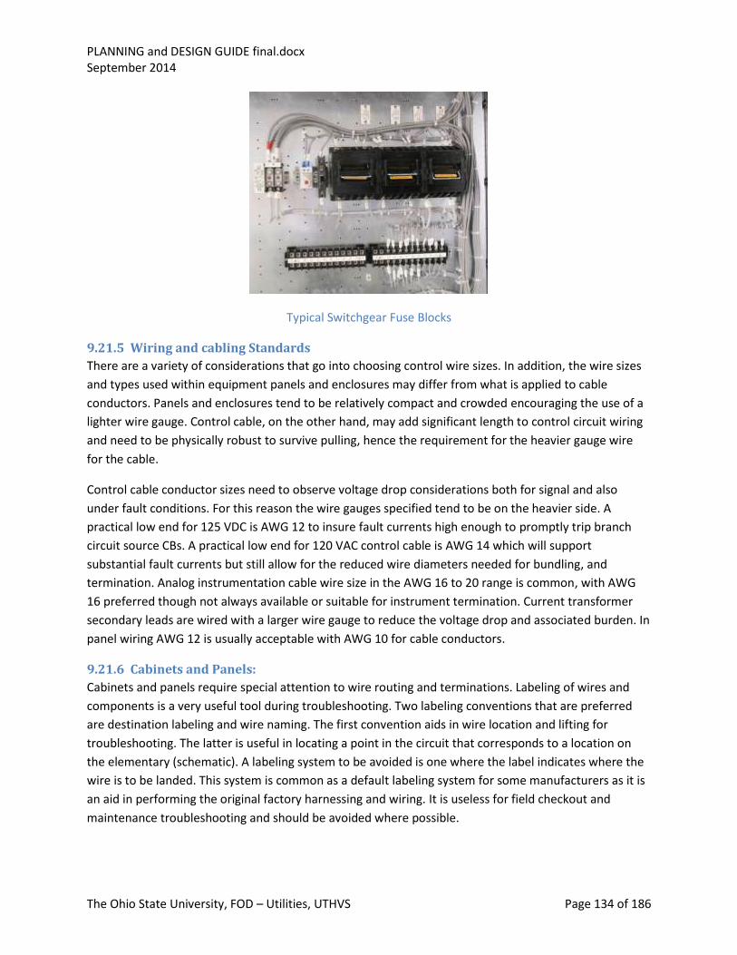
PLANNING and DESIGN GUIDE final.docx September 2014
The Ohio State University, FOD – Utilities, UTHVS Page 134 of 186
Typical Switchgear Fuse Blocks
9.21.5 Wiring and cabling Standards
There are a variety of considerations that go into choosing control wire sizes. In addition, the wire sizes
and types used within equipment panels and enclosures may differ from what is applied to cable
conductors. Panels and enclosures tend to be relatively compact and crowded encouraging the use of a
lighter wire gauge. Control cable, on the other hand, may add significant length to control circuit wiring
and need to be physically robust to survive pulling, hence the requirement for the heavier gauge wire
for the cable.
Control cable conductor sizes need to observe voltage drop considerations both for signal and also
under fault conditions. For this reason the wire gauges specified tend to be on the heavier side. A
practical low end for 125 VDC is AWG 12 to insure fault currents high enough to promptly trip branch
circuit source CBs. A practical low end for 120 VAC control cable is AWG 14 which will support
substantial fault currents but still allow for the reduced wire diameters needed for bundling, and
termination. Analog instrumentation cable wire size in the AWG 16 to 20 range is common, with AWG
16 preferred though not always available or suitable for instrument termination. Current transformer
secondary leads are wired with a larger wire gauge to reduce the voltage drop and associated burden. In
panel wiring AWG 12 is usually acceptable with AWG 10 for cable conductors.
9.21.6 Cabinets and Panels:
Cabinets and panels require special attention to wire routing and terminations. Labeling of wires and
components is a very useful tool during troubleshooting. Two labeling conventions that are preferred
are destination labeling and wire naming. The first convention aids in wire location and lifting for
troubleshooting. The latter is useful in locating a point in the circuit that corresponds to a location on
the elementary (schematic). A labeling system to be avoided is one where the label indicates where the
wire is to be landed. This system is common as a default labeling system for some manufacturers as it is
an aid in performing the original factory harnessing and wiring. It is useless for field checkout and
maintenance troubleshooting and should be avoided where possible.

PLANNING and DESIGN GUIDE final.docx September 2014
The Ohio State University, FOD – Utilities, UTHVS Page 135 of 186
Wire routing internal to panels should be via wire bundles rather than Panduit or similar constructions.
Panduit adds combustible loading to the panel and ultimately does little to organize panel wiring or aid
in wire tracing over a judicious bundling practices. It also uses up valuable panel space unnecessarily.
Terminations need to be arranged so as to allow proper placement of wire labels. The labels should be
sleeve type, indelible but not shrunk to the conductor. Termination areas for incoming cables need to be
laid out to facilitate multi-conductor cable breakout, tie down and jacket retention to the point of
conductor breakout.
Example of Labeling at Termination Area Note location of wire and cable labels
Wire harnesses traversing hinged panels or doors need to be arranged and anchored so as not to apply
any loading on terminations or a bending action on the wire itself. The wire should be high stranded to
afford flexibility and laced into bundles with abrasion protection. The wire action across the hinged area
should be twisting rather than bending to avoid wire fatigue and breakage due to the opening and
closing of the door or hinged panel.
Internal panel wire bundles should not be anchored with adhesive type wire anchors. These anchors
have relatively short service lives and cannot support any sustained loading.
Terminations should be ring type lugs. Split barrel and forked type are not acceptable. Cable
terminations to standard 600 V low wire density blocks (Marathon, Penn Union, etc.) should employ un-
insulated lugs to facilitate the use of clip leads for maintenance and trouble shooting. Higher density lug-
type terminations should have insulated barrels to avoid inadvertent shorting when using test leads.
Set-screw type terminations should be avoided where possible. When applied, terminations need to
employ ferules or tinning to improve the reliability of the connection. This is a serious concern for
applications where the wiring is done with stranded conductors, where terminations relying on a
pressure set screw with or without a pressure plate tend to flatten the stranded wire bundle over time
allowing the connection to loosen.

PLANNING and DESIGN GUIDE final.docx September 2014
The Ohio State University, FOD – Utilities, UTHVS Page 136 of 186
9.21.7 Cable construction:
We standardized on jacketed color coded multi-conductor cables for control applications. Color coding
with a standard color code facilitates checkout, maintenance troubleshooting and simplifies the wiring
drawings. The specific color code required is given in the BDS. Applying a jacketed design affords the
cable better protection during installation and aids in identifying wires for maintenance and testing.
Cables termination areas should accommodate conductor breakout as well as provisions for cable tie-
down. The cable jacket should be retained up to the point of conductor break-out as close as possible to
the point of termination and the cable identifier tag should be readable and located on the jacket at the
point of breakout. Paring back cable insulation to the point of entry to a panel or cabinet is not good
practice and will in most cases defeat the value gained from tagging the cable. Likewise removing the
jacket, before wire breakout would require it, also defeats this purpose. In instances where this practice
has been allowed, the installer should take measures to keep the cable wire contents grouped (bundled)
for as long as possible to aide in conductor and cable identification.
Cable material selection given in the BDS addresses a range on constraints placed on the typical
substation and plant designs by the operating environment and hazards analysis as well as the risks
associated with installation. A low smoke zero halogen design for a color coded multi-conductor
configuration that conforms to XHHW2 material compliance for the insulation (SIS for panels and
enclosures) addresses the need to survive a harsh chemical and ambient environment and limit
decomposition products from a possible fire or fault. Cable wire gauges are chosen to address concerns
for voltage drop and fault support in service. The avoidance of PVC in the construction of both the
insulation and the cable jacket limits the risk to sensitive electronics for corrosion and the risk to
personnel that could result from faults in both the control and power wiring.
The choice of stranding is left open to suit the application. Both have drawbacks. In general, individual
conductors should be stranded. Installation defects such as nicks and over-bending breakage show up
most frequently in solid conductor designs. Lugging, while in most instances is not necessary for solid
wire terminations, is not recommended. Stranded wire, on the contrary, is ideal for lugging but can be
problematic for mechanical or pressure type terminations. While ideal for traversing areas that require
flexure, stranded wire may require more extensive support or lacing in panels and control enclosures.
Because cables add most of the circuit wire length (resistance) in a design, attention needs to be paid to
the conductor sizing. CT wiring should be AWG 10, 125 VDC controls AWG 12, 120 VAC control AWG 14
and analog instrument AWG 16. Applying cable conductor sizes lighter than noted above would require
an analysis of voltage drops or in the case of the CTs, CT burden. Cable constructions using PVC should
be avoided for two reasons: off-gassing during electrical fires will produce very corrosive gasses, PVC
insulation is UV sensitive and tends to degrade in areas where natural light or fluorescent lighting is
present.
All control wiring should be copper based and installed without in-line splices. Where discontinuous runs
are unavoidable, intermediated terminations should be on terminal blocks with provisions for moisture
intrusion protection. If splices are unavoidable and intermediate terminations are not practical, in-line
butt splices are permitted. These terminations need to employ a welded barrel but splice with heat

PLANNING and DESIGN GUIDE final.docx September 2014
The Ohio State University, FOD – Utilities, UTHVS Page 137 of 186
shrink applied as a conductor insulator bridging the splice area with significant overlap of the adjacent
conductor insulation. In a multi-conductor cable, the individual conductor splice points should be
staggered so as not to have the splices bunch up at one point. Heat shrink should likewise be applied to
bridge cable jacketing over the entire length of the splice area. Note that in-line splices are an exception
to the rule and should always receive prior approval based on an engineering review. In-line splices to
provide T- or Y-splices should never be permitted as they defeat some of the basic advantages of
designing to a cable based design where cables can be assumed to have only two ends (a from and a to).
9.22 Potential Transformers and Current Transformers
9.22.1 Introduction
Potential transformers (PTs) and current transformers (CTs) are classified as instrument transformers.
For them to do their intended work accurately and efficiently they should be applied for signal purposes
only and not carry any load (burden) other that what is imposed by the metering or protective relaying
devices connected to the secondary circuits. PTs come in a variety of types and styles. For our
application, we generally use an iron core, wound transformer with two or more windings. CTs come in
two generic designs: bushing type (includes buss bar type) and auxiliary type with two windings.
Instrument transformers are applied where the power system voltage or current is too large to apply to
the metering or protective devices directly. For PTs this limit is about 600 V. For CTs the cut-off is not as
simple, as some protective devices are designed to be placed in line with the power circuit. In general
the practical cut-off starts at about 5 amps as most metering and protective relays are set up around
having a nominal reflected load analog current of 5 amps or less. In practice, the same is true for
voltage, as most metering and relaying expects to see in the range of 120 VAC or a near derivative such
as 67 V or 208 V.
9.22.2 PT Application
PTs are expected to reliably provide a secondary voltage value proportional to the measured primary
voltage. They are fused on the high side as well as the low side. The high side fusing is to protect the
high voltage source from a failure of the PT itself. The low side fuse is to isolate any secondary side fault
to avoid damaging the instrument transformer.
The PT ratio is selected to generate the desired secondary voltage for the normal high side operating
voltage. In some relay applications a PT may be applied to monitor a normally de-energized high side
source. In this case the ratio is selected to insure a relay is able to reliably detect the secondary voltage
level of interest for whatever monitoring or protective relaying scheme is in the application. Just as with
power transformers, the transformer connections need to be factored into the choice of ratio and
operating voltage. Since the PT may be being applied to monitor off nominal conditions as well, it is
important to make sure that the PT can handle the full range of applied voltage without saturation. PTs
applied to metering circuits may be required to conform to a certain accuracy class. This is where
burden (load) comes into play. PT characteristics are published to show what ranges of voltage and
burden stay within the PT accuracy requirements in application. The following illustrate two common PT
applications on the MV Distribution System.

PLANNING and DESIGN GUIDE final.docx September 2014
The Ohio State University, FOD – Utilities, UTHVS Page 138 of 186
Examples of Potential Transformer Installations PT Compartment in Switchgear (left) Structure mounted PT (right)
9.22.3 CT application
CTs are expected to reliably provide a secondary current value proportional to the measured primary
current. They are never fused on the secondary as this would serve no practical purpose and, should
they interrupt current, would produce dangerously high voltages and could result in internal damage to
the CT itself. Current transformers work on the principal that if you short circuit a transformer
secondary, the secondary current will be proportional to the primary winding current by the inverse of
the turns ratio of the transformer. Introducing burden means that the transformer will no longer be
effectively shorted but will produce a voltage on the secondary side winding. This voltage means that
there is flux circulating in the core and therefore an error current circulating through the transformer
magnetizing circuit (internal to the transformer) and not making its way to the secondary winding
terminals. This results in the secondary current no longer being an exact multiple of the primary winding
current, introducing instrument error. Small secondary voltages can be tolerated but if the burden on
the secondary circuit grows too large, the CT will experience a disproportionally large error as the iron of
the CT saturates and more and more current goes through the magnetizing branch bypassing the
secondary terminals. CTs are rated by accuracy class. The higher the number is, the more accurate the
CT. The number reflects the level of output voltage the CT can sustain without going into saturation. This
in turn relates to the percentage of primary winding current that actually is transformed onto the
secondary winding.
The CT ratio may be fixed or multiple ratio. The difference is in how many taps are made in the
secondary winding. Normally there is a full ratio tap and then a standard selection of sub ratio taps
selected to provide a wide range of tap ratios. CT ratios are normally given as a ratio of primary current
to 5 amps on the secondary winding. Multi-ratio CTs follow the same rule. For example, a 4,000 amp
buss might have a bushing CT with the ratio 4,000 to 5 or more commonly expressed 4,000/5. If it is a
multi-ratio CT it would be 4,000/5 MR with the ratios available fixed by standard.
CTs can produce high voltages not only from being open circuited. Most CTs are placed in proximity to
high voltage buss work and can pick up stray induced voltage. For this reason, CTs should always be

PLANNING and DESIGN GUIDE final.docx September 2014
The Ohio State University, FOD – Utilities, UTHVS Page 139 of 186
grounded at the first terminal block from the CT. This should be a shorting type block as should all other
terminal blocks carrying CT leads.
9.22.4 PT ratings and configurations
PT ratings are given in the standards and allow for a wide range of nominal and off-nominal conditions.
Some PTs are arranged for phase-to-ground connection with only one high side full line voltage rated
bushing. Some are provided with two high side fully rated bushings to facilitate line-to-line connections
as well as line-to-neutral or reverse-phase connections (for polarity reversal).
Grounding of PTs requires particular attention. All instrument transformers require secondary
grounding for safety from stray voltage. In the case of PTs, the decision of where to ground the
secondary is important particularly when the intent is to compare the voltages of two different sources
such as happens during synchronizing generators to a buss. The PT provides galvanic isolation for the
secondary winding from the primary winding. This allows the engineer to make YY, Delta Y or any
combination of three-phase or single-phase connections. Various placements of the secondary ground
can produce a wide variety of three-phase and single-phase voltage arrays including a variety of phase
shifts and phase reversals.
9.22.5 CT ratings and configuration
CT ratings are given in the Standards and allow for a wide range of nominal and off-nominal conditions.
Because it is common to see CTs in applications where the load current will be in a nominal range and
then see a sustained peak at higher values, most CTs we apply are rated to carry a secondary current of
twice the nominal 5 amps secondary without damage or overheating. Since CTs are intended to produce
a model or analog of the primary currents, their circuits tend to mirror the primary load circuits. This
means that typical CT circuits will be formed into delta and Y connections to faithfully reproduce an
analog of the primary equipment current loading. This is most commonly seen in the current
transformer circuits for differential protection of transformers.
Grounding of CTs requires particular attention. All instrument transformers require secondary
grounding for safety from stray voltage. In the case of CTs, attention to the physical placement of the
ground is also important. Normal good practice is to place the CT ground at the CT or between the CT
and Its first point of termination and provide shorting-type terminal blocks anywhere a CT wiring is
landed. Ground is also brought to each of these shorting blocks. Ground is also brought to any test
switches in the CT secondary circuit. These practices are followed to insure that the circuit can be
effectively shorted and referenced to ground anytime the instrument portion of the CT secondary circuit
is opened such as in relay calibration and testing.
9.23 PLC application
9.23.1 Basics
Standalone programmable logic controllers and their big brothers the distributed control systems have
their greatest value when dealing with controls that are highly integrated, heavily interlocked and/or
have a need for frequent reconfiguration. The technology is so powerful however that their application
in a variety of much smaller applications has become commonplace.

PLANNING and DESIGN GUIDE final.docx September 2014
The Ohio State University, FOD – Utilities, UTHVS Page 140 of 186
PLCs have advantages over relays in several obvious ways: Control logic changes are easier to
implement; the use of remote I/O can reduce installation costs; a lot more functions can be
accommodated at nominal additional cost and can be done digitally via communications without the
need for discrete I/O.
On the flip side, there are companion detractions. It is easy, in the absence of a rigorously applied
configuration control process, to lose track of programming changes: remote I/O can, with its
dependence on communications technology, introduce a greater level of exposure to what would
otherwise have been controls with little exposure; control system overreach, where features and
functions are introduced that overly complicate the HMI and potentially interfere with the basic control
actions of the system. In the big picture, it is important to balance the inherent benefits of the PLC with
the overheads and tendency to overreach in its application.
PLCs come with overheads in the areas of training, support technology, configuration control and design
discipline. A successful implementation relies not only on a sound testable logic development, but also
paying careful attention to the remainder of the application considerations such as operating
environment, housing, interface with the controlled process and equipment and operations and
maintenance interfaces. There is also a tendency to abuse the ease of logic reconfiguration by delaying
significant portions of the logic development and subsystem integration until startup and
commissioning. This tendency has the real potential to reduce or completely defeat the value of a
rigorous design development, check-out and commissioning.
9.23.2 Startup and shutdown states
Much of what a PLC or DCS will control is made up of integrated systems with power dependencies and
required sequences of startup, operations and shutdown. Beyond the specific control tasks programmed
into the PLC or DCS, the control system must be able to accommodate these initial, sequential and
terminal controlled system conditions to maintain safe fluid system and equipment conditions. This will
be most critical on control system shutdown and startup. Careful attention must be paid to control
system outputs during control system startup and shutdown to insure that startup initiation and
shutdown fail states are consistent with fluid system and controlled equipment needs.
Some typical examples are: selection of the power-down state for outputs; selection of forced-fail states
for loss of I/O resulting from loss of communications; use of retentive latches; selection of output status
during control system boot-up; supervision of system diagnostics and their impact on I/O. There is
always the choice to be made between “fail off”, “fail on” and “fail as-is”.
9.23.3 I/O Management
Beyond what was discussed above, proper I/O management can head off a lot of potentially adverse
effects on operating equipment. In a distributed I/O control system the partial loss of communications
can result in some rather undesirable control actions if not properly accounted for in the logic.
I/O whetting sources likewise need to be factored into the logic. A central source for powering inputs
and outputs is preferred but not always practical. Garnering input whetting voltage from a variety of
different local AC sources can be problematic for a host of reasons even with I/O that are “isolated”.

PLANNING and DESIGN GUIDE final.docx September 2014
The Ohio State University, FOD – Utilities, UTHVS Page 141 of 186
Non-isolated I/O or I/O that employ differential isolation are particularly susceptible to miss-operation
or damage. The preferred approach for PLC and for DCS applications is to develop the input whetting,
and where applied, the output isolation relay coil voltages internally to the control system. They should
be an isolated (from ground and any control battery) DC 100 V or greater for inputs and either an
internally supplied AC or DC to drive output relays. If DC cannot be tolerated by the I/O, an isolated
(from ground) AC supply obtained from a secure source should be used. Keeping exposure to the
common side of input and output supplies limited ( inside control cabinet with no exposure outside the
cabinet) will remove the need for I/O fusing as the circuits will have no loadable ground reference or
common buss exposure to shorting. Something to keep in mind about I/O fusing is that when it is
applied by the equipment supplier (permanently card mounted) it is because the manufacturer is
concerned not for circuit overload but customer wiring errors during startup. Once the equipment is
placed into service, the fuses generally serve no useful function. They do, however, remain in the circuit
and are a potential source of failure throughout the operating life of the system.
9.23.4 Environment and housing
One of the biggest drawbacks to microprocessor-based controls is the equipment sensitivity to
temperature and humidity. There have been significant improvements over the years and this has been
reflected in the operating ratings of the equipment. There is small print however. In the too small to
read print is the fact that the closer you come to published operating limits the lower the operating
reliability and the higher the probability of a random failure. A good general rule is to figure that the rate
of failure will double for every 10°C above 23°C. It is not good design practice to design right up to the
published design temperature limits of application for equipment. The more margin that exists between
the design limit and the actual application limit, the better the reliability and the greater the longevity of
the equipment. Pay attention to the proposed location for equipment that is being mounted outside an
area with a tightly controlled ambient. Also take into consideration the need to shield sensitive electrical
components for not only ambient temperatures and EMI but also shine (radiation) of proximate
equipment like steam pipes and also locating electrical components away from locations where leaks
could result in steam impingement, moisture intrusion or condensation. Where, historically, most
control equipment could live with the equipment that is being operated, the microprocessor controls
should be located away from heat generating equipment and in a controlled environment. Control
cabinet design also becomes important as all the heat generated internally to the controls and related
power supplies has to flow out of the cabinets before it can dissipate into the external environment.
Control cabinets should be large enough to dissipate internally generated heat without recourse to fans
or forced cooling. Fans are undesirable for a variety of reasons: They fail; they move dirt and
contaminants into the enclosure; they cause vibration; they consume power; and they encourage the
designer to use a smaller enclosure resulting in a greater degree of equipment and wiring congestion
than would otherwise be the case.
Equipment layout can assist in controlling cabinet internal temperature. The more temperature-
sensitive components should be mounted low in the cabinet with heat generating components such as
magnetics and linear power supplies mounted high and above the more temperatures sensitive
equipment. This is not common practice by most manufacturers or panel shops, where the practice is to

PLANNING and DESIGN GUIDE final.docx September 2014
The Ohio State University, FOD – Utilities, UTHVS Page 142 of 186
mount the heavier heat generating components low and under the temperature sensitive. To further
aggravate the situation, manufacturers are known for adding circulating fans local to the control
components to circulate the heat uniformly throughout the cabinet. While this may seem the intuitively
correct approach to cooling, it lowers the average internal air temperature often reducing the heat
transfer across the cabinet surfaces resulting in an overall higher internal ambient. Placing the heat
generating components high and not providing internal circulating fans allows the hot air to pocket
away from the temperature sensitive components and gives locally higher internal ambient air
temperatures at the top of the control cabinet which improves heat transfer to the external ambient
while keeping it away from the more sensitive components.
9.23.5 Wiring, cable and termination management
Most control system manufactures and panel shops are very good at control equipment layout and
compressing the cabinet design to minimize space requirements. On the other side of the coin, they are
almost unconcerned with field installation and maintenance. Because of this, we have historically taken
the initiative with control cabinet design efforts and gotten involved early in their designs to insure that
equipment layout, terminations and cable access are properly accounted for.
The preferred design for control enclosures has the field termination area segregated from the areas in
the panel where the control equipment (I/O, processors, power supplies, magnetics and
communications modules) are located. This field cable termination area contains only low density
termination blocks, cable marshaling space, provisions for cable access to the enclosure (top and/or
bottom) and provisions for securing the cables. All internal cabinet wiring should be to one side of the
field cable termination blocks and labeled. The cable marshaling area should be large enough for the
field cables to be laid down and secured one layer deep with cable tags visible and enough room for an
orderly breakout of the cable conductors. Cutting the cable jackets back and away from the color coded
conductors should be done only to the degree that it is needed to accommodate the wire breakout.
Bundling of multiple cable multi-conductor wires is not acceptable. Cable access to the top and/or
bottom of the enclosure should be unobstructed and a positive means of securing the incoming cables
provided. It should be noted that conforming to the above requirements becomes easier and with
better overall results when terminal block point assignments reflect the system cabling needs; for
example, grouping I/O terminations associated with a particular multi-conductor cable on the same
terminal block and adjacent to each other. Termination point layout to reflect commoning for whetting
voltages and for shields can also simplify and provide a much more orderly and congestion-free
termination area.

PLANNING and DESIGN GUIDE final.docx September 2014
The Ohio State University, FOD – Utilities, UTHVS Page 143 of 186
Typical Logic Panel Termination Compartment
Wiring in the remainder of the enclosure should observe standard wiring practice. Cable access should
be from the bottom or low on the sides of the enclosure. Top entry invites moisture intrusion and
moisture deposition on sensitive electrical and electronics contained within the cabinet. Instrument and
digital wiring should be routed away from 120 VAC and the higher DC voltages crossing a right angles
with long parallel runs avoided. We generally do not require color coding of labeled control panel wiring
by function or voltage.
9.23.6 Control Enclosure Power Distribution
Most control equipment enclosures do not contain power circuits or switching equipment (480 and
above). Where they do, the power equipment should be contained in an area separately accessed from
the control components and terminations. Access to the control areas should be restricted. However,
gaining access should not involve requiring de-energization of the control equipment or including any
imbedded interlocks such a door interlocks that trip off equipment or de-energize circuits.
9.23.7 HMI
HMI is a general term referring to the provisions in the design to accommodate operator interaction
with the control system. It can be as complex as an interactive display or it can be as simple as a control
switch and indicator light. Regardless of the complexity of the HMI, it needs to conform to a few simple
rules for its design: it needs to be readily accessible and located in a habitable area; it needs to conform
to applicable design conventions for orientation, operator action, color, operating sequence and
terminology. The key is consistency. Variety is not the spice of life when it comes to operating
equipment in an environment where there are hosts of different equipment with similar requirements
for operator interface.

PLANNING and DESIGN GUIDE final.docx September 2014
The Ohio State University, FOD – Utilities, UTHVS Page 144 of 186
Main Transformer Control Board DC Battery Meter Compartment
Tie Breaker Main Feeder Breaker Examples of Hardwired HMI Designs
Membrane type keyboards and touch screens should be applied with caution and generally are unsuited
for use in the field by plant or substation maintenance personnel. These technologies work much better
in controlled environments such as control rooms and offices where contaminants and background
noise are much less of an issue. Reliance on tactile feedback and audible feedback as is common for
touch screens and membrane switches is problematic in the field. Also such soft controls applied to
systems with slow response times prove very frustrating to the operator who expects to get a response
to their control action in real time and is not conditioned to a wait and see approach to HMI.
Examples of commonly accepted conventions are: Red is on, running, energized, open (valve), closed
(circuit breaker) or another way of thinking of it is red is conducting or risk; Green is off, stopped, de-
energized, closed (valve), open (circuit breaker) or another way of thinking of it is green is non-

PLANNING and DESIGN GUIDE final.docx September 2014
The Ohio State University, FOD – Utilities, UTHVS Page 145 of 186
conducting or safe. Control switch rotation right is to start, operate, arm, open a valve, close a CB.
Rotation to the left is to stop, turn off, disarm or reset, close a valve, open a CB.
Physical orientation of control devices is another area of standardization by convention. If the controls
are hierarchal a top-to-bottom orientation with the highest priority on top is customary. If the controls
are sequential, a top-to-bottom or left-to-right orientation with the first item on top or to the left is
customary. Indication should always be above or to the left of the control point (most people are right
handed and have their heads over their hands). Frequently accessed controls should be located in the
most ergonomically favorable location. Seldom used controls may be located away from prime control
locations. Emergency controls such as trip switches or push buttons should be clearly visible but placed
away from frequently operated controls to avoid accidental operation. In cases where miss-operation
could cause particularly dire consequences, resorting to a “two independent action” approach where
two independent operator actions are required for initiation may be required.
Orientation of control points by functional grouping is a popular approach particularly where the
process equipment have a clearly defined relationship such as would exist with certain pumps, valves
and tanks. The alternative approach commonly resorted to is a mimic where the equipment is shown as
connected symbols in a quasi-flow diagram. Each of these approaches has its strengths and limitations.
The functional grouping is very efficient for space utilization and more efficient for providing operator
interface in cases where there are many similar groupings, but relies heavily on the operator having an
understanding of the connectivity of the controlled components. The mimic is great for showing
connectivity but is relatively inefficient in space utilization. In practice, functional groupings are usually
used to control frequently-accessed related or auxiliary equipment groupings, where the mimic
approach is more commonly used to provide the controls for less frequently accessed controls such as
circuit breakers in a main switchgear line-up.
Where the HMI involves a control screen and not dedicated panel space the rules change somewhat.
The basic rules for consistency, hierarchal and sequential operations still hold since a component control
can be present on more than one screen. It is possible not only to show a component in a functional
grouping but also show its controls in one or more modes on a mimic as well. This added advantage is
neutralized to some extent by the need to maneuver between screens. Key to this design approach is to
keep the screens easy-to-read and not overly busy. The order (hierarchy) and content of the screens
needs to be more or less intuitive, and providing convenient links between screens showing the controls
or monitoring for any given component can be a very useful tool for addressing the need to maneuver
between screens. Component grouping by task is also an effective way to arrange component controls.
This can take a variety of forms ranging from a simple list of steps or sequential prompts, to a process
flow diagram with highlighted control points and associated status indications. The advantage of this
approach is that is ties preplanned procedural steps directly into the operator control interface and can
incorporate logic to verify correct sequence.
Alarming and provisions for presenting equipment status to the operator can take a variety of forms.
One is to integrate these indications with the associated components and controls. On a dedicated
panel, this may involve placing an alarm panel or a status display near the associated equipment

PLANNING and DESIGN GUIDE final.docx September 2014
The Ohio State University, FOD – Utilities, UTHVS Page 146 of 186
controls. The screen version might be to intersperse or incorporate alarm and status indication along
with the control points on the screen (color changes, flashing etc.). In the screen version, aggregating
alarm points on a separate display can also be incorporated to provide a stand-alone display and give
emphasis to off normal conditions that might otherwise get lost in the control screens.
9.24 Failure Modes Control system design tends to be a linear process starting with a control objective and ending with an
engineered way to achieve the objective. There is a tendency, however, to stay focused on the objective
at the expense of giving consideration to what the chosen design approach may produce in the way of
undesirable side effects or vulnerabilities. This would not be a problem if the designer were to go back
and review the design for possible undesirable side effects or vulnerabilities. However, all too
frequently, the designer gins up a design and then calls it a day having apparently (in their mind)
accomplished the intended result. A thorough design process works out a set of reasonable design
alternatives and then evaluates them for vulnerabilities, unanticipated accompanying results, as well as
a host of other things like operator load and cost effectiveness. Chief among these reviews is an
assessment of accompanying failure modes.
Failure modes can be grouped into two categories, System level and Component level.
9.24.1 System Level
System level failures refer to the net effect on the design as a whole that result from the range of
credible failures of a system or subsystem. In a way the system or subsystem is analyzed for how it can
fail and what the end results would be as if it were one big component. To get to this point however, it is
necessary to evaluate the individual component failures for the components that make up the system.
The design objective should be to end up with system level failures that are detectable and able to be
managed.
9.24.2 Component Level
Component level failure analysis takes known failure mechanisms and relates them to how the
component is being applied in achieving the intended task. Components, by in large, have generally
recognized principal failure modes. A failure analysis considers these principal failure modes with the
objective to find ways to reduce the effect of the failure either through significance or probability of
occurrence, and insure that the effect of the failure will be minimized or tolerated at the system level.
9.24.3 Principal Failure Modes of Components
Most simple control components have relatively recognizable principal failure modes: A control relay
coil failure is an example. There are however some failure modes that can become a principal failure
mode under certain conditions of application. An example would be where a control relay is normally
kept energized with the control action being taken via the back contact (b contact) of the relay. It is not
uncommon for the armature of a normally energized relay to have the coil potting material migrate to
the point where it will bind the armature rendering the relay mechanically incapable of dropping out
and completing the control action. Likewise, in this same scenario, some relay constructions (those with
the coil and contact space sealed and common) will, in the normally energized application, have the

PLANNING and DESIGN GUIDE final.docx September 2014
The Ohio State University, FOD – Utilities, UTHVS Page 147 of 186
surface of the back contact become coated and insulated by the vapor off the potting material, causing
it to fail to conduct. A good control design seeks to minimize the likelihood that a principal failure mode
will come into play or that the application will introduce additional principal failure modes.
9.25 Failure Analysis A failure analysis generally deals exclusively with principal component failure modes. This constraint is
placed on the analysis simply to make it doable. It also plays to probability of the event which is the
bottom line in any real life situation. There will always be the failure that comes out of the blue. We rely
on good design to shield us from the principal failure modes and automatic protective and manual
intervention to deal with the army of other things that can go wrong.
9.25.1 System effects
At the point where a component failure manifests at the system level, the design must be capable of
detecting the failure or its results and take some effective remedial action. In the control realm this may
be a back-up controller or the startup of additional or alternative system capacity. In the electrical
power realm this will likely be a protective device operation with the follow-on action to isolate the
failed components and initiate whatever automatic transfers are appropriate. The FMEA’s objective is to
affirm that the design has this capability and will not be blind to the need for such action.
9.25.2 Automatic Protective Response
Automatic protective response is generally required where the process is fast-acting and has
experienced an excursion to the point where the process or equipment is at risk of damage. In the
control arena this could involve a process shutdown, safety relief or operation of an isolation valve. On
the power side this is typically provided by a fault detection relay or the like. The key phrase here is fast-
acting. Slower acting failures may rely on human intervention (response to an alarm) with an automatic
response set closer to damage limits and in some cases at a more global system level of intervention
(involve shutting down more equipment).
The design should never rely on the same process sensors, I/O or logic to generate the automatic
protective action as is relied upon for the controls. It is best to think of this as a defense-in-depth system
where the regular controls operate to keep the process within acceptable limits and the protectives
form a boundary to allow some operating leeway but be there to act independently when the controls
fail to keep the process in bounds. The basis for this design approach needs to reflect an FMEA that
looks not only at the control components but also what can happen in the fluid system as the result of
fluid system failures, maintenance and operating errors.
9.25.3 Manual intervention
Manual intervention for fast-acting systems is a last ditch effort for most controls. Failures resulting in
slower transients can usually be dealt with effectively through manual intervention if the process and
equipment status information is available and reliable. Here again it is important to avoid relying on the
same process instrumentation used by the controls, as problems with these signals may be the reason
why the controls have failed. Redundant signals are not always required. Quite often diverse readings or
instruments that cover a different parameter range can be useful to the operator in detecting a control

PLANNING and DESIGN GUIDE final.docx September 2014
The Ohio State University, FOD – Utilities, UTHVS Page 148 of 186
excursion and diagnosing the problem. This is where system and component level alarms can be useful.
A pump in run-out aligned to a header with normal system pressure indicated might be used to diagnose
that the header pressure indication has failed. An overflow or high make-up alarm coupled with a back-
up pump running alarm might be used to diagnose a failed level control. Putting two level probes in the
tank, one for control and one for alarming would be a more direct approach. Either would address the
failure.
On the power side there aren’t many slow-acting transients but there are some important ones. Feeder
loadings and load transfers are one. Power equipment, such as cables, transformers, reactors and
switchgear, has some thermal reserve, which allows some level of continued operation in overload.
Since the protection for most of these components is fault, not overload, manual action is relied upon to
adjust or curtail load and bring power circuit loadings within component ratings. Failure to do so would
eventually result in component failure and prompt protective action. Protective action to handle fault
conditions is by design redundant or diverse. All elements of the primary MV distribution system as well
as MV power distribution in the plant and chiller facilities are covered by at least two zones of
protection with the exception of the radial street primary feeder circuits and their current limiting
reactors. These do have a backup zone of protective relaying in the form of main supply buss
overcurrent relaying set higher and slower to afford the necessary coordination. With the exception of
the street feeders, components of the MV distribution have differential protection as their first zone of
protection with coordinated time overcurrent as a secondary form of protective relaying. CAP banks are
relayed similar to the radial street feeders.
9.26 Power Dependencies Control systems like the equipment and systems they control have their own power dependencies. This
aspect of the control system is frequently overlooked during the design of a control system. Controls
that are needed only when the controlled equipment is operating can have their power derive from the
same source or orientation as the equipment. If the controls have to ride through the loss of the
controlled equipment, then the control power needs to be derived from an uninterruptable supply. For
AC this is commonly a UPS. For DC control this would be a central battery, in most cases. Introducing a
UPS supply or a DC battery dependency adds additional power dependencies to the picture and needs
to be reflected in the system FMEA as well.
9.26.1 Choice of power source
The choice of power source for a control system can be critical. Facilities that incorporate some level of
equipment design redundancy such as McCracken and the central chiller plants, operate with
equipment powered and controlled in system groupings with common power supply orientations and
some degree of automatic or manual back-up power design features. The control power for the
equipment needs to reflect the main power orientation of the equipment and be able to accommodate
equipment operation in the back-up power configuration. Quite often this is accomplished by deriving
AC control power from the starters or CPTs on the busses of the powered equipment. Where ride-
through capability is required, a critical AC system, standby power backed UPS, or a central DC control
buss is the preferred solution even though it does introduce additional failure modes to the design.
PLANNING and DESIGN GUIDE final.docx September 2014
The Ohio State University, FOD – Utilities, UTHVS Page 149 of 186
DC control is the preferred choice for switchgear and relay based tripping, interlocking and lock-out
control tasks because of its relative independence from the AC power system. Since a central DC battery
system can be designed to store a significant amount of energy, it is common practice to have it also
support the facility UPS as well as supply emergency shutdown loads for equipment that needs a
significant source of power immediately after a loss of main AC power. An example would be a steam or
gas turbine bearing lube and cooling system. Commonly the added cost and complexity of a central DC
system is justified, not simply by the control need, but also by one of the above as well.
9.26.2 Power Interruption considerations
Power interruptions pose some unique challenges for the control system design. An unanticipated loss
of prime mover power sets up conditions where the control system may have to manage an orderly
shutdown or prepare for a controlled restart. Some equipment can sustain a power interruption and be
allowed to re-start on its own without any control involvement. Other equipment needs to be run
through a sequence (boiler purge would be an example) before the equipment can safely be restored to
operation.
Interruption to the control power can also pose a challenge. The preferred way to whet I/O and power
control system electronics is to rely on DC throughout the design. The electronics would be powered
from power supplies that are powered off central DC or from separate redundant UPSs with the power
supply outputs auctioneered. I/O would likewise be whetted by DC, either an isolated DC supply or the
central battery; although that is discouraged because of the likelihood of DC voltage spikes and the
exposure to inadvertent de-energization when isolating battery grounds. A big fly in the ointment is a
common limitation in the design of large DCSs, which in their focus on low voltage controls (inherently
safe), are not designed to accommodate the higher DC-whetting voltages. This forces the control
designer to apply AC to get a high enough voltage to insure reliable operation. AC, derived from a UPS
output, cannot be auctioneered, making it dependent on a single source. I/O normal operating state
becomes a significant consideration under these circumstances, as even a momentary interruption of
the AC I/O whetting voltage, as would occur with a control voltage transfer throw-over could be
captured by the control system and be interpreted as a field contact change-of-state. A common
solution for this problem is to buffer (time delay) the input contacts with this potential for miss-
operation. However this may not always be an option and more sophisticated approached may be
required.
9.27 Cable Systems, Tray and Conduit
9.27.1 Basics
In an industrial environment such as we have in the Power Plant, central chillers and main substations,
electrical cabling is a much more structured and controlled process than it is for commercial and
residential. All power and control cables are identified by number with that number shown on project
drawings and in a cable schedule. Cable construction is controlled as is the method of routing the cable
through the facility. Running individual wires in conduit, as is common in commercial construction, is not
an accepted practice for control or power and allowed only for ancillary systems such as lighting. The
reason for this is simple. Cables have only two ends, whereas, wire bundles run through conduit and

PLANNING and DESIGN GUIDE final.docx September 2014
The Ohio State University, FOD – Utilities, UTHVS Page 150 of 186
split off at junction boxes can have many end points. Troubleshooting a cabled system is significantly
easier than for a wire in conduit system. The reliability of a cabled system is greater, as the individual
wires are protected by the cable jacket and internal constructions. Color coding the individual wires also
offers an advantage over ringing individual conductors out and labeling the ends of individual wires.
9.27.2 Identification and management
Cables and individual cable conductors are identified by numbering and, in the case of cable conductors,
either color coding or labeling. Each project maintains a cable schedule and the individual cable
conductors are shown on wiring diagrams. Cable numbering follows a system that codes the cable as to
service (control, power, etc.) Wire color codes conform to nationally recognized color coding based on
the cable conductor count and is given in the BDS.
Cables are routed in conduit or tray. The choice between these two approaches is based on operating
environment and economics. Conduit is galvanized metallic hard pipe. EMT is not approved for use.
Aluminum conduit is likewise not approved for general use for a variety of reasons including strength,
fire resistance and cost.
Tray is the preferred method of support for control and power cable when and where multiple cables
follow substantially the same path over a significant distance. There are two types of cable tray
construction: ventilated and solid. Ventilated tray is used to carry power cables and facilitates the
cooling of the power cables. Solid tray is applied for control or instrument cables where conductor
current loading losses are minimal.
The preferred tray construction is galvanized steel for strength, corrosion resistance and cost. Aluminum
is used when supporting MV cable to reduce the likelihood of inducing heating due to circulating
currents in the tray because of the phase conductor spacing.
Control tray is generally solid in construction and may also need to be covered to avoid buildup of dirt
and debris in particularly dirty environments.
All tray and conduit systems require grounding at multiple points. Grounds for tray should be run
external to the tray and connected to the individual tray segments at intervals. Conduit ends are
grounded at hubs or bushings. The requirements for grounding and support of tray and conduit are
given in the BDS Divs. 33 and 48.
9.28 Duct Bank Design
9.28.1 Introduction
The distribution of MV circuits using underground technology has distinct advantages. Such installations
are less vulnerable to environmental hazards such as wind and ice storms, floods, traffic accidents,
rodents and birds. On the other hand, they are, for the most part, out of sight and hence vulnerable to
surface construction and subsurface boring technologies. In areas of high construction activity, soil
subsidence and the placement of concentrated surface loads such as crane footings can pose problems.
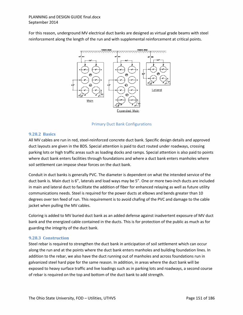
PLANNING and DESIGN GUIDE final.docx September 2014
The Ohio State University, FOD – Utilities, UTHVS Page 151 of 186
For this reason, underground MV electrical duct banks are designed as virtual grade beams with steel
reinforcement along the length of the run and with supplemental reinforcement at critical points.
Primary Duct Bank Configurations
9.28.2 Basics
All MV cables are run in red, steel-reinforced concrete duct bank. Specific design details and approved
duct layouts are given in the BDS. Special attention is paid to duct routed under roadways, crossing
parking lots or high traffic areas such as loading docks and ramps. Special attention is also paid to points
where duct bank enters facilities through foundations and where a duct bank enters manholes where
soil settlement can impose shear forces on the duct bank.
Conduit in duct banks is generally PVC. The diameter is dependent on what the intended service of the
duct bank is. Main duct is 6”, laterals and load ways may be 5”. One or more two-inch ducts are included
in main and lateral duct to facilitate the addition of fiber for enhanced relaying as well as future utility
communications needs. Steel is required for the power ducts at elbows and bends greater than 10
degrees over ten feed of run. This requirement is to avoid chafing of the PVC and damage to the cable
jacket when pulling the MV cables.
Coloring is added to MV buried duct bank as an added defense against inadvertent exposure of MV duct
bank and the energized cable contained in the ducts. This is for protection of the public as much as for
guarding the integrity of the duct bank.
9.28.3 Construction
Steel rebar is required to strengthen the duct bank in anticipation of soil settlement which can occur
along the run and at the points where the duct bank enters manholes and building foundation lines. In
addition to the rebar, we also have the duct running out of manholes and across foundations run in
galvanized steel hard pipe for the same reason. In addition, in areas where the duct bank will be
exposed to heavy surface traffic and live loadings such as in parking lots and roadways, a second course
of rebar is required on the top and bottom of the duct bank to add strength.

PLANNING and DESIGN GUIDE final.docx September 2014
The Ohio State University, FOD – Utilities, UTHVS Page 152 of 186
Since feeder circuit cables are a standard size, the capacity in an area is determined by the number of
conduits available to feed the area. As a standard design feature we always design for a minimum of one
spare or additional duct to accommodate pulling a replacement cable set where removal of the faulted
cable is not possible. Beyond this it is good practice to set the number of ducts in a new bank with a
mind to address future expansion anticipated for the area served by the bank. The logic behind this is
based on the fact that a substantial portion of the cost of a duct bank is in excavation and surface
restoration. Adding a few extra ducts is a good investment when the alternative is to put in a new duct
bank or rework an existing bank and disturb the finished surface. Looking ten years out, and in some
cases where large areas could be served, twenty plus years out into the future, planning duct bank
installations can be justified on this basis alone.
9.28.4 Spare Capacity
The practice of adding spare duct in duct banks grew out of the practice of installing some provisions for
growth anytime a main duct bank was installed. It is good practice and an efficient use of campus real
estate and works to minimize surface disruption. Cable failures, particularly on cables with lead jackets
or sheaths, were notoriously difficult to remove to clear the conduit for its replacement. Having spare
duct many times was the only way to restore normal power to an area. The widespread use of fiber duct
(Orangeburg) further exacerbated the situation. Running spare ducts in laterals and load ways is a
relatively new practice. There are a couple of considerations driving it. For laterals, as they are run in
pairs, a spare would require a third conduit and, in concrete an unbalanced duct design. Adding a forth
duct is almost a necessity. Further, many laterals are or may in the future be run with a third feeder.
Again, a structurally balanced duct bank design would call for a spare even if one could rationalize not
having a built-in spare. On load ways, the length and exposure of the load ways associated with
developments such as the NRD expose the building served to a prolonged outage when its load way is
damaged. Damage can come from a cable failure but will most likely happen as the result of subsurface
area improvements such as the addition of communications, or utility upgrades where surface
excavation takes a back seat to directional boring.
The BDS has standardized on a 2 X 2 duct configuration for laterals and a minimum of 1 X 2 for load ways
that run any significant distance and have exposure to construction or landscaping activity.
From an installation cost perspective, most of the cost of a duct bank is in the excavation and final
surface restoration. The savings in trenching for a 1 X 2 over a 2 X 2 bank is negligible. The material
addition is one 5” PVC duct for the load way and two ducts plus two rebar for the lateral at most, and in
many cases, only one additional conduit.
9.28.5 Standard Design Configurations
The standard duct bank configurations are given in the BDS DIV 33. Other configurations may be used in
areas where the standard configuration is not practical. Two major considerations govern the duct bank
design: strength and thermal release of cable heating losses.
Because of the history of building additions and rebuilding, soil subsidence is a real concern. Duct banks
are constructed to resemble grade beams, with rebar located on the top, bottom and sides of the bank.

PLANNING and DESIGN GUIDE final.docx September 2014
The Ohio State University, FOD – Utilities, UTHVS Page 153 of 186
Thermal consideration relating to removal of cable electrical losses governs the arrangement of the
ducts in the bank. Duct banks are designed so that each power cable carrying duct is located along an
outside wall of the bank. There are no power ducts located internal to the bank where the heat loss has
to pass by another duct to get to the soil beyond the limits of the bank.
Duct banks are located a minimum of two feet apart in parallel runs and at least ten feet away in any
orientation from any sources of heat such as steam lines. Avoidance of parallel runs with steam lines is a
desirable feature as failed insulation on a steam line can introduce heated ground water in the area of
the lines and result in an elevated ambient and potential cable de-rating or accelerated cable aging.
Where crossing a steam line or condensate line cannot be avoided, in addition to any insulation present
on the line, there must also be an insulated barrier to heat flow positioned between the pipe source and
the duct bank. Normally such a barrier would extend several buss duct bank major diameters but not
less than ten feet beyond the area of intersection in both directions. The insulating barrier, where
applied, must be suitable for direct burial and able to tolerate the high temperature environment
created by the steam line.
There are a range of standard MV duct bank configurations sanctioned by the BDS. They all have some
common features: First, there are no interior conduits. All conduits are on an exterior wall of the duct
bank. Second, all duct banks are reinforced with steel rebar and are fabricated with high strength (4,000
psi) concrete. These features are present to insure proper cooling and to afford superior strength to
accommodate soil subsidence. Third, duct banks are located below grade, below the frost line, to
protect the concrete from degradation due to freezing and thawing cycles. There are also rules for
locating duct banks away from gas lines as well as sources of heat. Fourth, all configurations are
constructed with concrete that has been dyed with a red pigment. This is done as a last ditch effort to
alert anyone uncovering the duct bank to the fact that MV cable is contained within. Other precautions
in place such as tear tape and mapping also help avoid accidental uncovering or damage to buried
electrical distribution duct bank.
Main duct bank which carries the main primary feeder circuit pairs and third feeders is constructed in a
2 X 3 or 2 X 4, 6” duct configuration which also includes centrally placed 2” conduits for fiber optic cable
to support relaying and utility data and communications needs. The number of ducts in a bank depends
on the anticipated cable-loading of the duct bank run initially and in the planning cycle (10 to 20 years).
A six-duct bank is designed to handle two circuit pairs and a third feeder with one spare conduit
available for repair or rerouting. An eight-duct bank is designed to handle up to three circuit pairs and a
third feeder. Since only certain circuit pairs are likely have associated third feeders, this configuration
allows more flexibility and capacity for circuits. Duct banks theoretically could be designed for more
than eight ducts, however manhole congestion and difficulty getting the concrete slurry to distribute
evenly during pouring place limits on Utilities’ willingness to design duct banks with more than eight
ducts.
Laterals are designed around a 2 X 2 array of 5” duct, with one 2” duct central to the array. This design
supports the two primary circuit laterals, a third feeder if needed and a spare. The duct size is 5” and not

PLANNING and DESIGN GUIDE final.docx September 2014
The Ohio State University, FOD – Utilities, UTHVS Page 154 of 186
6” to economize on material and take advantage of the fact that cable pulls are seldom too long for a
750 kCM cable.
Load ways are designed around a 1 X 2 array of 5” conduit. This assumes that the load way will feed one
transformer or one end of a unit substation. It does not include a 2’ conduit for relaying or data as would
be the case for the lateral or main. One duct is for the service and there is a spare to facilitate cable
replacement if and when required. Some installation may be designed around only one conduit where
the load way duct bank is short or the major part of the run is in steel conduit in building space and
reasonably accessible. The spare conduit may in some special cases serve as access for low voltage
circuits or fiber optic.
There are other approved duct configurations employed to overcome buried obstacles such as tunnels
and sewers. They are approved on a case-by-case basis by Utilities after concerns for structural integrity
and thermal release have been adequately addressed. In rare cases, a duct bank containing an interior
conduit may be approved. An example of one such case is the SCCCP power feed which crosses Cannon
Drive in a 3 X 4 array. In this design, only the exterior conduits are considered to be suitable for normal
current-carrying duty (10-6” conduits in all). The two interior ducts are reserved for low voltage, low
load application(s) and as a possible spare for MV load cable with some administrative restrictions (de-
rating) applied.
9.28.6 Location and access
Duct banks should be routed in the clear, away from buildings or other structures. It is best to align duct
banks with utility corridors and along area planning street grids to limit the risk of future development
overhead and the need for duct bank relocation. Locating outside of a future construction area also has
the benefit of reduced risk that construction activity will result in damage to the duct bank. If a new or
existing duct bank is located near a construction area, the construction contractor is responsible to
protect the duct bank from any heavy loads such as those that would be imposed by truck traffic and
cranes.
9.29 Manhole (Vault) Design
9.29.1 Basics
Electrical manholes (vaults) are a design feature of the duct bank system. Their size and spacing is
determined by the need to house cable splices and limit the length of cable pulls. They are normally a
pre-cast design which limits costs and are outfitted with standard cable mounting and grounding
hardware. Manholes are not designed to be waterproof and can be expected to flood regularly and need
pumping when access is desired. Their construction is highway rated even though we strive to avoid
placing them in roadways or high traffic areas where access could be disruptive or limited. The size of
the manhole is standardized and given in the BDS along with a variety of specific design details including
access dimensions. In limited cases manholes may be stacked, though this is not a normal practice. The
depth of the manhole and height of the throat (riser) are critical to cable pulling and need to be limited.
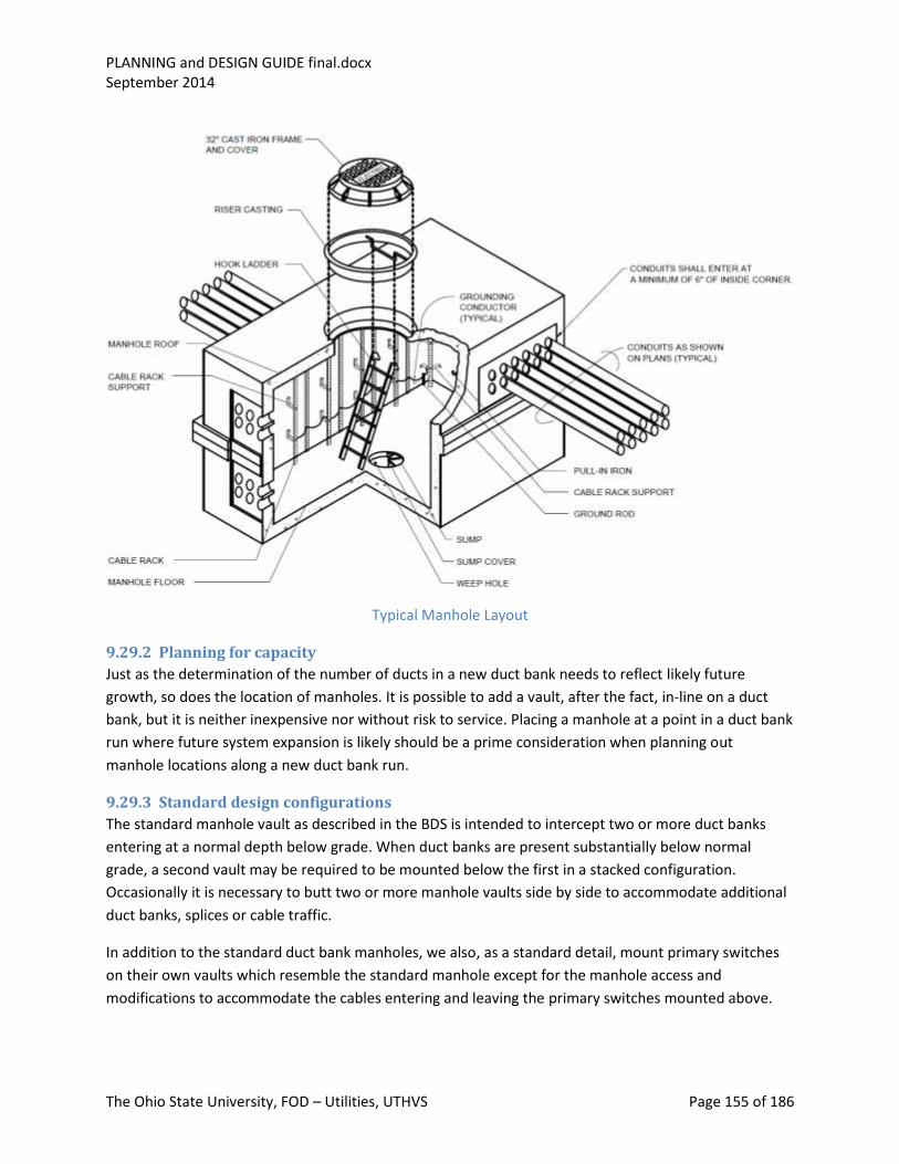
PLANNING and DESIGN GUIDE final.docx September 2014
The Ohio State University, FOD – Utilities, UTHVS Page 155 of 186
Typical Manhole Layout
9.29.2 Planning for capacity
Just as the determination of the number of ducts in a new duct bank needs to reflect likely future
growth, so does the location of manholes. It is possible to add a vault, after the fact, in-line on a duct
bank, but it is neither inexpensive nor without risk to service. Placing a manhole at a point in a duct bank
run where future system expansion is likely should be a prime consideration when planning out
manhole locations along a new duct bank run.
9.29.3 Standard design configurations
The standard manhole vault as described in the BDS is intended to intercept two or more duct banks
entering at a normal depth below grade. When duct banks are present substantially below normal
grade, a second vault may be required to be mounted below the first in a stacked configuration.
Occasionally it is necessary to butt two or more manhole vaults side by side to accommodate additional
duct banks, splices or cable traffic.
In addition to the standard duct bank manholes, we also, as a standard detail, mount primary switches
on their own vaults which resemble the standard manhole except for the manhole access and
modifications to accommodate the cables entering and leaving the primary switches mounted above.

PLANNING and DESIGN GUIDE final.docx September 2014
The Ohio State University, FOD – Utilities, UTHVS Page 156 of 186
Since MV manholes and vaults can be expected to carry both circuits of a circuit pair as well as other
pairs, there is a requirement to fire-wrap the individual cables in an approved fire tape. The
requirements for the tape are given in the BDS. The tape is to protect the taped cable from a failure in
an adjacent cable or splice. Taping is generally considered sufficient protection for design level faults
and further protection such as placement of barriers is generally not required. In some cases,
particularly cable tray and instances where pre-existing cables are unprotected, placing barriers in tray
installations between cables may offer an acceptable alternative to taping. This is a practice used more
in vaults than in manholes.
Grounding provisions in MV manholes called for in the BDS are designed to accommodate component
grounding as well as provide a substantial grounding system for the cables themselves. Cable splices
have their shields brought out to ground and all 4/0 insulated ground conductors are also brought to
ground. A ground buss is provided in manholes and vault areas to facilitate this grounding practice.
9.29.4 Location and Access
Manhole vaults are intentionally located away from vehicular traffic areas. This is to insure that if access
is required it can be gained without serious disruption of vehicular traffic or the need to take
extraordinary measures to redirect traffic. They are also restricted from areas where people are likely to
congregate. This is to limit the likelihood that a cable or splice failure that could result in the lifting of a
manhole cover causing injury to the public. Manholes are also not allowed to be located in buildings,
basements, lobbies or in areas where access for utility personnel would be limited.
We do not provide locking devices to manhole covers nor do we apply fiberglass or other lightweight
constructions to MV manhole covers for this same safety reasons given above.
9.30 Equipment Enclosure Design (Small, Medium, Habitable)
9.30.1 General Considerations
The design requirements for electrical equipment enclosures are driven by the application, location,
environment, and contents. Most will fit one of the standard NEMA classifications with NEMA 1 general
purpose in environmentally controlled and clean environments, and NEMA 12 and NEMA 4R being the
most common for locations where dirt and moisture could pose a problem for the contents.
Some panels and enclosures are required to contain both sensitive, electrical control or monitoring
equipment, and some form of process connection such as a sensing line or process connection. Where
possible this should be avoided, however, where unavoidable, it is best to locate the process
instruments and associated fittings and valves low and away from the sensitive electrical components.
Enclosures should be sized to provide adequate natural cooling for the contents and their operating
losses.
Enclosures should be designed with adequate space and appropriate penetration areas to accommodate
field-cable terminations and conduit access. In moisture-prone applications, penetrations should be

PLANNING and DESIGN GUIDE final.docx September 2014
The Ohio State University, FOD – Utilities, UTHVS Page 157 of 186
from the bottom or low on the enclosure to minimize the likelihood of moisture getting on moisture-
sensitive components.
Enclosure designs that do not require wire harnessing across door hinge areas and door-mounted
equipment are preferable. If space permits, the best form of enclosure in an area where dirt and traffic
is present is an enclosed, self-standing cabinet where the operator interface is from the front panel and
the access for wiring and maintenance is via a door at the rear.
In protected and relatively clean environments such as exist in substation control houses, an open-panel
or rack-type design with a skinned-panel front and open access to wiring is a useful design approach.
9.30.2 Equipment Enclosures
Equipment enclosures take a lot of forms. The simplest is a box designed to be mounted on a wall or
rack containing electrical equipment. In the more complex form it may grow to resemble what was
provided at West Campus Substation to house the 15 kV switchgear and associated auxiliary equipment
and systems. All equipment enclosures share certain requirements: cooling (and heating if located
outdoors), personnel access, cable access, maintainability for all contents, and appropriate isolation
from hostile environments such as rain, dust, chemicals and condensation.
West Campus Substation Equipment Enclosure
9.30.3 Panels and cabinets
Control panels and cabinets are designed to house electrical components in a way that supports their
installation and wiring, servicing or adjustment, and removal for repair or replacement. The panel design
needs to reflect the needs of the equipment, as well as the needs of the operator and the constraints
placed on the structure during installation and cabling. In situations where the panel contents are likely
to expand with time (provision for future additions or spares), initially designing-in the capacity for a
reasonable expansion is prudent.
The layout of components needs to observe adequate spacing to allow access to terminations. Terminal
space needs to be provided to allow for an orderly marshaling of field cables. Provisions for
management of jacketed, multi-conductor cables must be provided along with space to train panel
inter-component wiring bundles. Provisions for grounding components as well as securing the panel or
cabinet should be provided. Ground-based panels or cabinets should generally be on housekeeping
pads. Equipment or structure-mounted cabinets should not be mounted where vibration could result in

PLANNING and DESIGN GUIDE final.docx September 2014
The Ohio State University, FOD – Utilities, UTHVS Page 158 of 186
loosening of equipment or fatigue or fretting of control wires and cables. Where equipment is to be
contained in a simple wall-mounted box, providing a back plate or back plane supported away from the
exterior walls of the box helps insure that the required number of box wall penetrations can be
minimized and the resultant risk of moisture intrusion reduced.
Special attention should be paid to equipment mounting location and details to assure that the
components and their terminations can be accessed for testing and de-termination. The components
themselves also need to be mounted is a way that supports their removal without the need to de-
terminate and remove other components.
9.30.4 Major Equipment Enclosures
These enclosures may resemble buildings when the contained equipment is large or complex. At West
Campus Substation, the MV switchgear enclosure which contains all the substation MV switchgear, also
for efficiency, contains the substation protection and control equipment, station service distribution,
power factor correction CAP banks, and DC battery systems as well. The vault under the enclosure,
provided as an area to marshal feeder cables, also houses the feeder circuit reactors and provides
additional space for CAP banks if needed in the future.
Equipment enclosures can present a whole range of design considerations beyond what would be of
concern for panels and smaller cabinet-style enclosures. These structures are usually placed outside and
require suitable foundations, weatherproofing and guttering. The enclosure itself must be accessible
and habitable not only for maintenance access but also for operations access, and may need to support
habitability needs for extended periods of time. Provisions need to be made for safe access and egress,
lighting and HVAC. West Campus Substation’s main equipment enclosure is bi-level with a vault that
needed to be accessed from the switchgear level and had a separate room for CAP banks that needed to
be kept separate from the switchgear area for environmental and safety considerations. Habitability for
extended periods of time also raised the question of how best to manage arc flash risk.
9.30.5 HVAC
HVAC needs to be applied to meet the requirements of the components contained within the enclosure
and the personnel access requirements to maintain a habitable work space. Switchgear and power
components can generally rely on an enclosure that is self-cooled as long as the losses generated by the
equipment are nominal. Lightly-loaded switchgear usually would apply as would CAP banks and LV
switchgear. Line reactors and large motors would not apply. Forced outside air would normally be
acceptable for cooling an equipment enclosure that houses power equipment with typical levels of load
loss such as series line reactors and motors. Air conditioning would normally be required or at least
prudent for enclosures that contain sensitive electronics and power electronics such as inverters and
battery chargers. Some batteries also require reasonably tight environmental controls to assure
adequate capacity and battery life. Heating is generally required for humidity control when dealing with
power equipment. However ancillary equipment such as electronics, batteries and liquid-filled systems
may have the need for controlling ambient temperatures within tighter bounds than would normally be
experienced in an unheated structure.

PLANNING and DESIGN GUIDE final.docx September 2014
The Ohio State University, FOD – Utilities, UTHVS Page 159 of 186
At West Campus, the main switchgear portion of the enclosure is heated as well as air conditioned. The
remainder of the enclosure and vault are not heated. Ground effect heating from the vault walls and
floor which are substantially below the frost line and daily warming cycles are relied upon to keep the
enclosure and vault temperature above outside ambients for the periods where heating would normally
be required. Cap bank and reactor operating losses are also a contributing factor to this heating effect.
WCS HVAC and Fan Units
9.30.6 Pre-Fabrication
Equipment enclosures come is a wide range of sizes and construction. They all contain some level of
prefabrication which means that not only the equipment specifications are needed for purchase but also
fabrication specifications and a host of specification requirements normally associated with site
construction and site accommodation. In addition to this, the larger enclosures such as we installed at
West Campus, come in sections to enable or facilitate transportation. This adds more specification
requirements and places constraints on equipment arrangement to the overall specification envelope.
Using the West Campus equipment enclosure as a case study, the enclosure shipped in ten sections. The
sections were nominally 50 feet long and 16 feet wide. The whole structure (240 ft by 32 ft) had to fit on
top of a subsurface vault and steel support structure capable of supporting the entire enclosure
structure once assembled. Access (stairways) had to be designed to communicate the enclosure
volumes with the vault, as was also the case for the design of the vault and CAP room ventilation. The
switchgear enclosure volume which is climate controlled was to be operated at a slight positive pressure
over the outside of the enclosure and the adjacent CAP room and vault areas.
The enclosure specification included most of the requirements of BDS DIV 33 as applied to a
conventional substation design. Tray, conduit, grounding, cabling, and wiring requirements were directly
applicable. Equipment arrangement became a joint effort with the switchgear manufacturer who had
the overall enclosure and contents scope of supply responsibility. Key components of the station
contained within the enclosure were specified directly by OSU: battery, charger, inverter, control and
protection panels, AC and DC distribution and switchgear initial arrangements. OSU, after a review of
the vendor’s interconnecting non-segregated buss-duct arrangements, also took the initiative to modify

PLANNING and DESIGN GUIDE final.docx September 2014
The Ohio State University, FOD – Utilities, UTHVS Page 160 of 186
the initial buss-duct design to place the buss duct under the enclosure floor and into the vault area for
arc flash, exposure and space considerations.
Enclosure equipment arrangements needed to take consideration of the pre-fabrication aspect of the
design. All switchgear-related and most of the ancillary electrical equipment was assembled at the
fabricator’s facility then broken down for shipment and reassembled onsite. The BDS has a requirement
that splicing of power and control cable is not permitted, only intermediate terminal boxes with
terminal blocks. Rather than try to install an army of terminal boxes to accommodate all the control
wiring between switchgear and panels, the design approach was taken to minimize the need for such
connections by arranging the equipment and switchgear in a manner so that no cable needed to
traverse more than one, or in some cases, two shipping splits. This facilitated de-terminating cables and
laying them back into the overhead tray system for shipping. This approach was followed for all control
cables. Power cables were generally not run during fabrication but designed so that they could be run
external to the enclosure (under the floor) in conduit after the enclosure could be assembled onsite. The
result was a design with virtually no circuits run between shipping splits needing intermediate terminal
boxes with the exception of enclosure lighting.
The use of prefabricated equipment enclosures can save significant project costs over what would
otherwise be a “stick build” performed with local construction forces. It can be instrumental in
accelerating the overall design and construction process as well and, if properly managed, optimize
equipment layout and avoid significant costs associated with the adaptation, design and construction of
the more traditional building-type enclosures. One drawback is that it does almost always require that
any intended future expansion be accommodated in the initial design, which in this case was not a
serious drawback.
9.30.7 Factory Testing and Erection
With equipment enclosures, factory acceptance testing can take on a whole new dimension. A portion
of what would have been construction QC and preoperational testing is now being performed at the
equipment supplier’s facilities or at the facility that builds and populates the enclosure. The exact split of
testing activities needs to be established early in the project to limit duplication of effort yet insure an
adequate and complete testing program.
In the case of switchgear, the switchgear manufacturer will, in any event, perform some preassembly
and testing in their factory as part of their own QC program and as an efficiency move as they have
immediate access to spare parts and skilled labor. Some of this testing will be duplicated at the
enclosure assembler; particularly the portions that are needed to verify installation accommodation and
control wiring by the enclosure manufacturer’s workforce. The real potential for duplication of effort
comes between the checkout and testing work done at the enclosure assembler’s facilities and the
preoperational testing, checkout and commissioning activity onsite. A second complicating factor is that
typically the equipment manufacturer will have their startup people performing the testing activities at
the enclosure vendor’s shop and the University will employ its own professional relay checkout
organization (RCO) there and again onsite. Our experience with this aspect is that factory-testing
activity and RCO-testing are definitely not comparable in detail or completeness, and quite often in

PLANNING and DESIGN GUIDE final.docx September 2014
The Ohio State University, FOD – Utilities, UTHVS Page 161 of 186
scope. There are two obvious options available. One is to allow the enclosure checkout to go to
completion under the auspices of the equipment vendor and take no credit for it onsite. The second is
to have the RCO present at the enclosure checkout and testing witnessing the vendor’s checkout and
performing any supplemental checkout and testing needed and then rely on the RCO judgment as to
what testing should be repeated onsite prior to service. Either way, there will be some duplication of
effort.
At WCS we attempted to bridge these two approaches by involving the Associate’s engineering at the
enclosure testing phase. This was the source of continuing confusion and lost effort throughout the
remainder of the testing onsite and into startup. There were other weaknesses in approach that became
evident as well, as the phases of the project progressed.
Switchgear shop drawings’ availability became an issue for the enclosure manufacturer and the AE,
which was further compounded by the difficulty the AE had in completing their design work, which in
turn delayed finalizing the non-switchgear scope of design for the enclosure manufacturer. In an
attempt to remedy this situation, the AE did some remedial checkout and performed some protective
relay work in parallel with the enclosure vendor and switchgear manufacturer. The result, a fragmented
and incomplete design, made checkout activity at the enclosure vendor’s facility almost impossible. In
the end, the RCO activity onsite turned out to be virtually what would have had to be done for a site-
constructed facility. Most of the confusion could have been avoided if the normal rules governing
vendor supplied equipment had been observed and fully reviewed, and approved shop drawings had
been required at all critical points in the project.
One added confusion also surfaced. The role of the switchgear manufacturer’s checkout staff, the AE’s
relay engineer and the RCO got blurred at one point and, for a while, created confusion over what scope
of involvement remained for the RCO. That issue however was quickly resolved onsite and the site
portion of the checkout and testing proceeded relatively normally.
In the final analysis, despite the radical departure from the norm represented by the prefabrication, and
all the effort to avoid duplication and excessive overlap, the startup and checkout ended up being
essentially what would have been needed for a site-build but a bit more compressed. The lesson learned
was that commissioning was the least impactful of the changes brought about by the pre-fabrication
and that a strict adherence to past practices in design control and construction scheduling were the
most.
9.30.8 Site Testing and Commissioning
Site testing and commissioning theoretically should not be directly affected by the fact that the
equipment came in an equipment enclosure rather than in tested subsections, and was field installed
and wired. In reality, there are some impacts that need to be accommodated. The dividing line between
the manufacturer’s, contractor’s, and RCO’s scope of responsibility tends to become a bit blurred when
it comes to checkout and testing responsibilities. The other big potential difference is in the area of
installation documents. Up-to-date construction documents (Commissioning Set) may be incomplete or
delayed because the construction process happens in two stages. As-built drawings from the enclosure

PLANNING and DESIGN GUIDE final.docx September 2014
The Ohio State University, FOD – Utilities, UTHVS Page 162 of 186
manufacturer serve as the basis for the site construction and ultimately the commissioning sets. This can
delay work or cause work to proceed based on preliminary design documents complicating checkout
and final commissioning activity. At WCS we entered commissioning with as many as five versions or
markups of key documents and at the conclusion of the project, had to reconcile a minimum of three
sets of as-builts.
9.30.9 Arc Flash
When a large, enterable enclosure contains a significant energy source such as MV switchgear, arc flash
becomes a real concern. An enclosed area is not a good place to be under arc flash conditions because
of the confined volume and egress limitations. Our preferred approach was to apply arc resistant gear
that contains the arc that results from a high energy electrical fault and vents it outside the enclosure
and away from personnel and equipment. This consideration should extend not only to the MV gear but
also to any associated buss work and power components such as reactors and CAP banks. In the West
Campus design, the MV switchgear is arc resistant design vented to the exterior with exterior access to
switchgear terminations and for testing. Reactors are located in the vault area below the equipment
enclosure which is not a confined area or intended for extended periods of occupancy. The power factor
CAP banks, which contain the capacitors and associated switchgear, are housed in a separate room from
the switchgear with guarded or limited access to any frequently inhabited space. The buss work
incorporated to interconnect the six sections of the MV switchgear that make up the three substation
MV busses is located under the enclosure above the vault. This approach meets the requirement for arc
flash without requiring all the major MV components to be arc resistant.
9.31 System Voltage Regulation
9.31.1 Power quality and voltage regulation
Power quality on the Main Campus MV Distribution system is primarily an issue of voltage regulation.
The main substation busses are powered from the secondaries of six 138 kV to 13.8 kV transformers
equipped with load tap changers (LTCs). Their function is to provide a distribution voltage regulated to
within intended limits (13.6 to 13.7 kV), and to compensate for any voltage excursion trends caused by
AEP’s operation of their 138 kV system and any loading effects caused by the daily load cycle of the
campus. The LTCs are quite effective at maintaining distribution voltages within this band but are
inherently slow and do not compensate for short duration power system disturbances such as may
result from switching on the AEP System or large motor across-the-line starting or faults on the OSU
distribution system. Faults on the AEP system are historically the only events that originate on the AEP
system that are significant enough to produce noticeable power quality issues for main campus loads.
The transients caused by faults on the AEP system are of short duration, commonly 4 cycles or less but
may be enough to trip of some motor drives, trip off some building automation systems, and even result
in emergency diesel starting.
9.31.2 Central voltage control (LTCs)
Both voltage control and power factor correction are done local to the main substation busses. Since the
design of the MV distribution system is radial, this allows for source voltage source regulation on all
feeder circuits. Power factor correction is a secondary mechanism for voltage support. Since CAP bank

PLANNING and DESIGN GUIDE final.docx September 2014
The Ohio State University, FOD – Utilities, UTHVS Page 163 of 186
control involves only seasonal switching, its main effect is to bias the LTC operating range and keep the
LTCs operating around the zero point which is recommended for the health of the LTC. The net
sustained effect on buss voltage is not a factor, only the step-voltage change due to the switching; and
even this is relatively insignificant when the main substation busses are on dual feed.
9.31.3 Series regulators
Series regulators are not being applied to the MV distribution system. The combination of the regulated
source buss, low cable impedance and limited circuit length maintains circuit voltages well within spec.
Future expansions of the campus MV distribution may incorporate series regulators however.
Series regulators operate to boost or buck line voltage to compensate primarily for line drop. This is
more of a concern for overhead distribution where line impedance (reactive impedance component) is
greater than for cable. In the future, if we go to a distributed approach to powering campus load
expansion, series regulators may be incorporated into the design in place of central LTCs, not to
compensate for line drop, but to compensate for variations in the AEP 138 kV supply voltage. (See
Distribution Planning).
9.32 LTC Control
9.32.1 Introduction
The Main Campus MV Distribution System operating voltage is regulated by load tap changers (LTCs) on
each of the secondary windings of each of the main three winding transformers at OSU and WCS
Substations. The high side no-load tap changers are set based on the AEP 138 kV transmission voltage
schedule to permit the secondary side LTCs to operate near the center of their operating range. The
LTCs operate in buck or boost to control the voltage on their associated busses, compensating for 138
kV transmission voltage fluctuations and the effect of campus load changes. Each main substation buss
is normally aligned to the secondaries of two different main transformers. The busses can be operated
either in single feed where one transformer’s secondary supplies power to the buss via its LTC, or can be
powered from both feeds in a paralleling configuration. In that configuration, LTC operation must be
coordinated to insure that the LTC choice of operating tap is optimal and the LTCs don’t have the
tendency to hunt or circulate reactive.
9.32.2 Modes of Control
There are two basic main buss powering configurations: All main buss-tie breakers open, and busses
separately fed (singly or dual fed); one main transformer out of service and a tie CB closed reducing
what was a three buss system to what is effectively a two buss system. In both of these configurations
automatic buss voltage control is available and requires the available winding’s LTCs to operate in
coordinated fashion.
There are three modes of LTC operation: Manual, Automatic-Independent, and Automatic-Parallel.
In Manual, the LTCs can be raised or lowered manually to control buss voltage. This requires the
operator to periodically monitor buss voltage and adjust to keep within the intended buss
voltage range.

PLANNING and DESIGN GUIDE final.docx September 2014
The Ohio State University, FOD – Utilities, UTHVS Page 164 of 186
In Automatic-Independent mode, the in-service transformer winding LTC monitors its aligned
buss voltage and regulates that voltage within prescribed limits automatically. The controller has
programmed limits to regulate the buss voltage within. Once the voltage goes outside these
limits, a raise or lower command will reposition the LTC one step at a time to correct buss
voltage appropriately. Since this mode is used only when the powered buss is in single feed
configuration, there is no need for the LTC controller to coordinate with the any other LTC
controller.
In the Automatic-Parallel mode there are two LTCs acting to regulate the same buss. Their
controllers are programmed to switch over to a DeltaVar 2 mode of operation where the two
controllers not only monitor buss voltage, but also monitor both contributing main feeder
currents. Their action is to regulate buss voltage and at the same time bias their control to act in
the direction of sharing reactive current equally. This action minimizes the amount of circulating
current between parallel buss feeds and avoids any tendency for the LTCs to buck each other,
hunt, or go unstable. Operating in this mode is not exclusively reserved for normal operation
with both main buss feeds paralleled. There is also a maintenance mode allowed where, if a
main transformer is removed from service, the associated MV buss-tie breaker can be closed
and the combined two buss segment can be powered from the remaining alignable transformer
windings with their LTCs in Automatic-Parallel mode.
DeltaVar Controller and Front Panel
Main Controller (top) Backup Controller (bottom)
9.32.3 Limits of safe operation
Our normal limit of operation for the main busses is 13.6 to 13.7 kV. Most of the voltage perturbations
originate with AEP on their 138 kV system with some voltage drop due to reactive loading on the

PLANNING and DESIGN GUIDE final.docx September 2014
The Ohio State University, FOD – Utilities, UTHVS Page 165 of 186
transformers originating with the main campus load. The high-side taps on the main transformers were
selected to match the AEP 138 kV voltage schedule in a such a way as to range the load tap changers so
that maintaining our buss voltage limits allows the LTC to cycle through their zero tap positions
periodically and not have a sustained bias either in the buck or boost direction. Seasonal CAP bank
switching and campus load changes assist in this regard. We try to keep main buss voltages less than 14
kV and above 13.3 kV as the distribution system and primary service transformers are rated at 13.2 kV.
Accounting for normal feeder system load drop, these values keep primary operation well within a ± 5%
regulation. Of the two limits, the high limit is most critical as the surge protection on the distribution
system feeders is rated 10 kV, 8.4 MCOV.
9.32.4 Safeguards and back-up controllers
Load tap changers are controlled individually by controllers in their respective control panels which
monitor the voltage of the buss being fed by the LTC. When the main buss is being fed from one main
transformer secondary, the buss voltage is directly controlled by that LTC and its controller. When the
buss is being fed from two transformers, the LTC controls share the control and operate to share the
reactive load as well. This allows the system to operate at its most efficient loading without circulating
reactive between the transformers. In order to insure that a controller failure does not result in
excessive reactive circulation and main feeder overloading, a back-up controller is applied to supervise
the main LTC controller operation and lock it out if a miss-operation is detected. Miss-operations are
alarmed on the substation supervisory system.
9.32.5 Voltage monitoring and alarming
The abnormal operation of the LTCs is alarmed over the substation supervisory. Exceeding the limits of
buss voltage regulation is also monitored and alarmed via supervisory. These limits are set on the low
end (13.2 kV) in consideration of the more sensitive building systems equipment, and at the high end
(14 kV) by distribution system transient overvoltage protection.
9.33 CAP Bank Design and Control
9.33.1 Introduction
OSU and WCS substations are equipped with centralized power factor correction on each of their main
busses. OSU substation has two 7.2 MVA banks on each buss. WCS has two 7.2 MVA banks on each main
buss with provisions for an additional two if required. Power factor correction is done centrally on the
main campus, rather than on a distributed basis, as is more common for overhead distribution systems.
Centralized power factor control is done for a variety of reasons relating to the design of the distribution
system, operating complexity and cost. Doing PF correction centrally is less efficient as it does not
provide any benefit relating to reduced losses in the street feeders, however most street feeder loadings
are relatively low (well less than one third of cable and reactor design limits), making the cost of placing
shunt capacitors out on the radial distribution feeders difficult or impossible to justify. The principal
value from having the CAP banks is that they allow us to get full capacity from our main transformers,
and assist in regulation of buss voltage and optimize LTC operations.

PLANNING and DESIGN GUIDE final.docx September 2014
The Ohio State University, FOD – Utilities, UTHVS Page 166 of 186
Power factor correction done centrally on the six main substation busses is done in stages with each CAP
bank rated at 7.2 MVA. Based on an anticipated power factor for each of the buss feeders at a bit under
0.9, it would theoretically take three banks per buss to correct for the buss-load with the substation
operating at its design rating of 126 MVA, and unity power factor. If the power factor correction is to be
done at the high side of the main transformers that count goes up to four per buss. The choice of 7.2
MVA per bank is somewhat arbitrary, but turns out to be a reasonable compromise between the
number of switching devices required and the step-size in voltage transient caused by switching activity.
The arrangement of the CAP banks at OSU and at WCS is different. The difference reflects the history of
the facilities and the space available for the banks.
At OSU, there are three indoor banks, one per buss. Two banks were added that space limitations
required to be placed outside the control house at the west end. Two of the three original indoor banks
had integral switching devices, the third (Buss 200) had only its buss breaker for switching. The two
outside banks were installed with their own switching but shared a common connection point with their
respective indoor bank. This arrangement allowed individual switching but left both exposed to faults
caused by wildlife getting into the exposed portions of the outdoor switch. Buss 200 recently had a
second bank added. It was powered off its own buss feeder breaker. The availability of spare breakers
on this buss after the recent re-circuiting made this possible.
At WCS the CAP bank feeds are arranged in pairs, with each buss equipped with two feeder breakers
designed to sub feed two CAP banks. Each CAP bank has an integral CB rated to do routine capacitor
switching. In the initial construction only half of the CAP banks were installed. Space is provided for the
remaining 6 banks should they eventually be called for. All installed CAP banks are located inside the
main equipment enclosure at the east end of the structure. There is a provision for up to six more banks
in the vault immediately beneath the installed banks. The WCS installation design was chosen because it
offers superior operating flexibility, efficient use of buss feeder breakers and facilitates maintenance. All
breakers are capacitor rated, however the breakers at each CAP bank are the AMVAC design which is
rated for the routine switching duty and should require less routing maintenance.
9.33.2 Modes of Control
Presently we do not perform automatic CAP bank switching. Instead we operate with one bank in
service year round and, at OSU, we turn the second bank on to compensate for the additional system
load that occurs between April and October. Consideration is being given to adding automatic CAP bank
control in the future, however, historical VAR loading records indicate that most of the time PF
correction with seasonal CAP bank switching is within or near ± one half a CAP bank worth, raising a
question as to whether the extra switching and equipment wear and tear can be justified. A secondary
consideration is the effect of CAP bank switching on building loads and building automation. Most
variable speed drives are capable of handling the voltage transient experienced with CAP bank
switching. Some building automation systems are not. If we are in the normal buss operating mode with
two transformer feeds to each buss, the voltage transients experienced are not very severe. With a buss
on single feed, as occurs when we are doing certain switching operations, or if there is a main
transformer outage, or AEP is doing work in the 138 kV system, this can be a problem.

PLANNING and DESIGN GUIDE final.docx September 2014
The Ohio State University, FOD – Utilities, UTHVS Page 167 of 186
Presently there is no provision in our electrical rate structure that would encourage tighter power factor
regulation and encourage the addition of automatic CAP bank control on the system.
9.34 MV Facility and Equipment Rodent and Pest Control
9.34.1 Types of threat
Almost all of the Main Campus MV Distribution is underground and fully insulated. Exposure points are
limited to air-insulated portions of the Main Substations (OSU and WCS), and primary service
connections. The most common form of rodent or pest issues originate with squirrels, larger foraging
mammals such as raccoons or originate with nesting birds and insects. The areas of greatest exposure
are the termination areas of the outdoor CAP banks and the secondary terminations and switch
structures on the main substation transformers. Hornet’s nests are a personnel concern and frequently
are found in the lock assemblies of outdoor primary switches and primary transformers. The MV cables
and associated terminations do not appear to be attractive to gnawing rodents, as there is no history of
failures due to that form of rodent damage.
9.34.2 Avoidance and Mitigation
Mitigation has taken the form of an electrified fence around the three main transformers at OSU
substation and a program to remove trees from the perimeter walls or fences of the substations. This
keeps animal traffic away from the vulnerable areas. Wall modifications were completed at OSU
substation to reduce the likelihood that squirrels would access the CAP banks via the substation wall. At
WCS, the CAP banks are an indoor design. The main transformers at WCS have a wider phase-spacing
and have fewer areas on the structures amenable to nesting.
Presently there are no plans to apply rodent guards to any of these exposed conductors on structures
although commercially available designs are being investigated.
9.34.3 Moisture intrusion and Enclosure Design
Electrical equipment and moisture don’t mix well. Failures resulting from moisture intrusion can take a
variety of forms. The most obvious are electronic circuit failure and faulting of high voltage circuits.
Some results are more subtle. Moisture intrusion can result in intermittent failures such as LV circuit
grounding or spurious operation of controls. Latent effects such as corrosion are also an issue.
9.34.4 Sources and design features
Sources for moisture intrusion can be leaks, intentional wash down of equipment, or simply
condensation accumulation. Design features intended to avoid or guard against such events include:
Locating equipment away from sources of water
Mounting sensitive equipment in NEMA 12 enclosures (3R where applicable)
Restricting conduit and cable entry into enclosures to the bottom or lower sides of the
enclosure.
Applying sealing glands or packings to conduit entrances for the top.
Installing screened weep holes as drain points in cabinets.
PLANNING and DESIGN GUIDE final.docx September 2014
The Ohio State University, FOD – Utilities, UTHVS Page 168 of 186
Applying sealing or packing glands to conduit runs entering equipment enclosures from above to
avoid moisture ingress through the conduit from higher elevations.
Paying close attention to how ARC Flash exhaust ducts are run and exit structures, making sure
that ducts are sloped away from sensitive switchgear areas, with appropriate drain points
added. Duct openings to the outside must be sealed against windblown moisture in the form of
rain and snow. These openings need to also be vermin proof and able to resist minor pressure
differentials such as are caused by wind, thermal effects, and ventilation.
Control of condensation can pose its own challenges. Condensation occurs when moisture-laden air is
allowed to enter an enclosure and condense on a cool surface. This can be a slow process where the
moist airflow is allowed to deposit moisture on cooler internal structures gradually over time, or result
from a temperature cycling such as would occur from time to time with seasonal or daily temperature
and humidity cycles. A common way to deal with condensation and dew point cycling is by installing
shutdown heaters in equipment. These are effective only if they heat the surface to be protected above
ambient. If shutdown heaters are applied without regard to what is to be protected, they can actually
produce the adverse result of causing moisture to transport from a location where it has been collecting
and onto surfaces requiring protection.
9.35 UPS Systems
9.35.1 General Introduction
The UPS is an AC power supply that is designed to provide continuity of power (single- or three-phase)
without detectable interruption through an interruption of normal facility AC power. UPS systems are
built up of several key components; a stored energy source (battery), an inverter, and some form of
automatic bump-less transfer device. It is generally applied to loads that cannot withstand even a
momentary power interruption or where the load needs to have continuity of service for a defined
period after interruption of power. Commonly there is a UPS, a normal power source, and some form of
emergency or standby power source. The UPS needs to be able to ride through the interruption of the
normal power source and provide service until power can be restored by the emergency or stand-by
source. The UPS load is guarded from a failure of the inverter or AC generating portion of the UPS by
providing a solid state transfer device capable of switching load off the inverter stage and over to an
alternate supply in under a quarter cycle in most cases.
Central facility UPS systems usually are installed in pairs to provide two independent UPS power sources
for critical control and instrumentation. UPS power is more failure prone that most standard low
voltage distributions. Its advantage is that it can be there when normal AC sources are lost. Its
disadvantage lies in its complexity and the fact that it is a current limited source and is therefore more
vulnerable to branch circuit faults and various sources of energization transients such as switching type
power supplies. Providing two separate UPS-backed busses gets around this limitation. It does however
require some attention to detail when it comes to the design of control equipment power supplies and
internal power distributions in the control systems themselves. A typical power supply configuration has
the critical control components powered independently from both inverter supplied distribution panels
with their DC outputs either auctioneered or powering equipment specifically designed to accommodate

PLANNING and DESIGN GUIDE final.docx September 2014
The Ohio State University, FOD – Utilities, UTHVS Page 169 of 186
two independent sources of DC power. Some control equipment comes already equipped to accept two
sources of AC power which removes any need to do external DC auctioneering.
Standalone UPS at McCracken (left) and Paired Units at WCS (right)
9.35.2 Design intent
The design intent in applying a UPS system to any critical power supply application should not be
reliability. UPSs are complicated and prone to failure. Further they are inherently current limited;
meaning that for a fault on a load circuit they will turn off, relying on the solid state transfer device to
successfully transfer the load (and fault) to a second stiffer source capable of producing enough fault
support to quickly clear the fault. The best way to describe the design intent behind applying a UPS is to
make the best of a difficult situation. Ride through for a power system interruption is what you can
design for. Reliability has to be engineered into the load, normal power sources, and standby power.
9.35.3 Selection of appropriate loads
The choice of what goes on a UPS is critical. UPS loads should be limited to what has to have continuity
of service and cannot survive even a short interruption (Emergency or standby power starting times in
the order of ten to sixty seconds). Loads with large inrush currents such as some classes of power
supplies should be avoided. Motor loads and loads with significant reactive requirements or with a
known propensity for causing voltage spikes on switching should not be included. A general rule is the
fewer loads the better from an exposure standpoint and few if any magnetics without surge
suppression.
9.35.4 Design features and accessories
Typical design features are: a regulated, filtered, standby-AC power source capable of supplying fault
support and carrying the total inverter load with significant margin (150 to 200%); a solid state transfer
switch to transfer load over to the AC standby source and return it without significant interruption; a
means of manually transferring inverter load over to a standby source with isolation capability to
facilitate servicing the inverter and solid state transfer device; a source of stored energy (battery)
capable of sustaining the operation of the inverter throughout the intended duty period which may

PLANNING and DESIGN GUIDE final.docx September 2014
The Ohio State University, FOD – Utilities, UTHVS Page 170 of 186
range from minutes to hours depending on the service requirements of the load; a system to monitor
the health of the battery, inverter and transfer device.
Variants of this basic design may add a second inverter in place of, or in addition to, the interruptible
standby source, multiple batteries or a more complex switching arrangements to facilitate testing and
maintenance.
9.35.5 Integration with Plant or Substation DC systems
Our applications for a UPS typically are in a facility, plant or substation, where there is also a central DC
system. Where this is the case, adding the UPS load to the existing DC facility load can usually result in a
reasonable increase in battery size and a lower installed cost. When this approach is followed, the
design needs to be able to shed the inverter load before it brings the central battery to a discharge state
where it can no longer support the other facility DC control loads. On a back fit to an existing central DC
system, it is not only the battery that needs to be re-sized. The battery charger may also require an
upgrade if the inverter does not have provision for its own alternate source of DC (usually a built-in
rectifier powered off normal or standby AC).
Most of our facilities are operated by a centralized plant control system (PCS). With all the eggs in one
basket, so to speak, the need for a failure-tolerant uninterruptable source of control power (AC)
becomes critical to maintaining plant availability. These facilities are provided with two UPS systems
operating independently down to, and including, their distribution cabinets. They will usually have
independent DC sources and also independent alternate interruptible standby generation backed
regulated low voltage sources as backup.
9.35.6 Standalone UPS applications
At facilities where there is no central battery, the central battery system is insufficient, or the added
exposure cannot be tolerated, a standalone system may be applied. These can be purchased as a system
(most common) or it can be built up as a collection of individual components (battery, charger, inverter,
transfer switch, regulated filtered AC standby transformer). The advantage of the package is obvious.
The system engineering has been done and only the application engineering remains. The component
approach adds the system engineering to the application engineering but allows for a more robust
design and some design flexibility. There are arguments for and against both approaches. The biggest
drawback to the package approach is that these systems are aimed primarily at the commercial market
and tend to use shorter lifetime components with high replacement costs.
9.40 HMI Design and Labeling
No matter how well-designed a system may be, it always has a potential fatal weakness: human
involvement. While there can be no assurance that a foolproof design is in fact foolproof, there are
measures that can be taken to lessen the probability of human failure.
Attention-to-detail when designing controls and displays is a key element in avoiding human error. To
this end, having a reference design for commonly applied equipment, and having a set of basic criteria
for the design of all like activities, the various HMIs involved can go a long way toward maintaining a
PLANNING and DESIGN GUIDE final.docx September 2014
The Ohio State University, FOD – Utilities, UTHVS Page 171 of 186
familiar work environment. This in turn assists in developing and retaining a trained staff intimately
familiar with the equipment and related safe and efficient work methods.
9.40.1 Selection of controls and displays
Controls and displays should exhibit a high level of similarity in layout and functionality. Conventions
should be carefully observed. Tactile, visual, or audible feedback should be employed where they aid the
operator in making a selection or adjustment. It is preferable to standardize on a particular productline
and manufacturer for control switches and metering. Operator familiarity with the control hardware is
important when the operator is expected to be concentrating on the process. The operator should not
need to deal with the disorientation caused by a wide variation in indication or metering presentation or
unnecessary variants for accomplishing the same control action with an HMI. In an otherwise stressful
situation: Boring is Good.
9.40.2 Component and controls labeling
Labeling is important. No matter how familiar an operator is with the equipment and its controls, there
is always the potential for distraction and confusion. In addition, when things do not go the way they are
expected to, the operator may only have seconds to assess the situation. Having equipment ID’s, power
source information and in some instances instructions readily available can be extremely helpful.
Labeling should be easy to read. Nomenclature should match between controls and the equipment.
Abbreviation should be used sparingly and with consistency. Labels should be positioned where the
action is to be taken. Avoid clutter. Equipment usually comes from the factory with labels designed by
the manufacturer and applied to address their own liability concerns at the expense of customer
operating efficiency and trained operator safety. A “Danger High Voltage Keep Out” sign on a cabinet
door that has to be routinely opened by the operator is an unnecessary distraction and detracts from
other notices that are much more directed toward safe operations such as warnings about possible
back-feed or requirements for PPE.
9.40.3 Access, location and environment
HMI access is critical. All too often a designer will locate controls by default in locations with access
issues, in locations where there are adverse ambient conditions of noise, temperature or humidity, or in
locations that are difficult to reach. Lighting is also an issue. General access lighting is often not
adequate for control stations or for working with certain types of control screens. Care needs to be paid
to customized task lighting. Illumination levels as well as glare need to be considered.
Locating controls where the process indication is not readily available or requires the operator to leave
the station (go behind equipment or climb a ladder) is an invitation to work without feedback. Put the
indication where the control action is being taken whether it is in a central control room, local control
station or control screen.
9.41 Feeder Pair Design
9.41.1 General Discussion
Primary feeder circuits on the main campus MV distribution system fit a standardized design described
in detail in the MV Distribution Planning Study. They are laid out in pairs, powered from different main

PLANNING and DESIGN GUIDE final.docx September 2014
The Ohio State University, FOD – Utilities, UTHVS Page 172 of 186
substation busses and supply power to primary service connections (primary select switches and
primary transformers). A given building service may be fed from either circuit in the pair or have its load
split between both as in the case of some double-ended substations or multiple substation designs.
UTHVS maintains a main switching chart that lists the individual services along with associated sub-
feeds. This chart lists the individual primary select switches along with their normal circuit assignments.
It also shows main substation alignment and highlights critical services such as patient care (PC),
laboratory animals (LA), and veterinarian services (V). Feeder circuits are rated at 400 Amps but with a
combined circuit pair limit set administratively at 400 Amps. These limitations are under review and
some campus circuits may be raised to over 500 Amps and converted to a new rating system that takes
advantage of the MV distribution system modernization and widespread use of the standard main duct
bank design.
MV feeder circuits are fault current limited by series reactors in the substations to 9,000 Amps fault
current to keep the primary switch interrupting devices within capacity. The system is made up of over
thirty distribution circuits campus-wide. Each circuit pair is loaded to a limit that allows the circuit pair
combined load to be carried on one circuit of the pair while the other is outaged (forced or scheduled).
Circuit reactor additions after the initial total system upgrade in 2004 employ a 600 Amp reactor design
which permits street circuits to exceed the administrative combined limit of 400 Amps under emergency
loading conditions or when there is an associated third feeder present.
Circuit metering is done at the individual feeder breakers and passed on to a central supervisory system
for logging and trending. Some meter elements of this system have wave form capture capacity and can
support fault analysis as well.
The system is a radial system with upwards of 30 or more buildings on a radial circuit pair. Some
facilities have active automatic transfer capability active in their services; others are switched manually
for the loss of a feeder circuit. The decision to allow automatic transfer is based on the activities
performed in the building provided service and the loading conditions present on the distribution
system and substation main busses.
Feeder circuits originate from any of three substations: OSU, WCS and Smith. Each have a three-main
buss system, with Smith sub fed from the main busses at OSU, and WCS independent and powered
separately from the AEP 138 kV system.
9.41.2 Design limits
Design limits are set by the ampacity of the primary feeder cables and the current limiting reactors at
400 Amps. The feeder supply breakers are rated 1200. The primary select switches are rated 600 Amps
continuous with a 40 k Amp make and hold. Primary switch resettable fault interrupters, where present,
are rated 12,000 Amps.
9.41.3 Design objectives
The design objectives for the MV distribution feeders is to provide reliable N+1 power to main campus
buildings under normal conditions and continuity of service while one of the circuits in the circuit pair is

PLANNING and DESIGN GUIDE final.docx September 2014
The Ohio State University, FOD – Utilities, UTHVS Page 173 of 186
out for maintenance or construction. The N+1 criterion extends back to the main transformers up to
their attachment to the AEP 138 kV system. Feeder circuit relay protection follows the fault detection
rather than an overload strategy. The fault clearing times are kept short for phase and ground to limit
fault damage and risk to personnel and public. There is no automatic reclosing action on the individual
feeders. When they trip on overcurrent they remain de-energized until re-energized manually.
Coordination with individual primary services is primary transformer fuse to substation CB over current
relay coordination and is intended to minimize the potential for risk to the public of explosion or fire.
9.41.4 Normal and Emergency Loading practices
Loading practices reflect a conservative strategy for loading circuits to an administrative limit that is
unlikely to cause equipment damage or premature equipment aging. However, we will put continuity of
service ahead of this consideration under emergency operating conditions. In general we prefer to keep
most of the MV system operating well under 50% of its continuous ratings to prolong life, reduce
operating losses, and avoid the need to do extensive system inspections under load such as infrared
radiography. Operating an all-copper system at low load levels dramatically reduces the probability of
heat-induced failures in cabling, splices and terminations.
9.42 Third Feeder Design
9.42.1 General Discussion
The “Third Feeder” is a relatively new addition to the main campus MV distribution system. It was
introduced under the Switch and Cable Replacement/Med Center CCCT Make Ready Project to improve
system reliability during circuit outages and to expand the capacity of existing and new feeder pairs
being added in these projects. A more detailed description of this design is given in the Distribution
System Study. With the addition of the new West Campus Substation, it also afforded a convenient and
inexpensive means of providing of geographic source diversity to the Med Center which up to that point
had been completely dependent on OSU Sub for its non-emergency power.
9.42.2 Design limits
Third feeder circuits are cabled in 750 kCM rather than the 500 kCM used in the normal primary feeder
pair circuits, and rated along with their reactors for 600 Amps continuous and 750 Amps emergency. As
these circuits normally carry no load, there is also some thermal reserve available which would increase
the emergency rating to over 800 Amps for a short period (a few hours). The actual duration is under
study.
9.42.3 Design objectives
The design objectives for the third feeder were to improve primary circuit utilization, improve overall
system reliability particularly during periods of scheduled circuit outages for construction, reduce
switching load on Utility personnel, and improve post-forced outage load restoration times. A third
feeder is designed to provide backup to one or two primary circuit pairs in normal operation. In standby,
it is designed to supply standby power to one circuit pair while already powering the loads normally
aligned to an additional primary circuit pair.

PLANNING and DESIGN GUIDE final.docx September 2014
The Ohio State University, FOD – Utilities, UTHVS Page 174 of 186
9.42.4 Normal and Emergency Loading practices
Under normal loading for the associated primary circuit pairs, the third feeder would carry no load but
be energized and ready to assume load. When a circuit of a circuit pair is scheduled to be outaged for
construction or maintenance, its load would be transferred to its third feeder, and then transferred back
once the scheduled work is complete. In the event of a primary circuit forced outage, the circuit loads
would transfer to its third feeder. In the event of a loss of power to one of the substation main busses,
two associated primary feeder circuits would transfer to the third feeder bringing its loading up to its
nominal continuous rating.
The emergency loading strategy comes into play when an event such as a main buss failure results in the
automatic transfer of two feeder circuits onto a third feeder that is already serving loads from a primary
feeder circuit powered off the unaffected main buss. In this case the circuit load transferred to, and the
load already being served by, the third feeder could exceed the third feeder’s continuous rating,
potentially requiring operator intervention and some effort toward load curtailment should the buss
restoration time be excessive. One thing working in the favor of this strategy is the distribution system
peak load profile. Peak periods are relatively short and cyclical, allowing load to potentially fall away
before any need to manually curtail load. This effect would also facilitate a load curtailment strategy
that would permit a more leisurely and selective load curtailment execution based on projected load
requirements for the more prolonged curtailments that could result from events like buss faults or
breaker failures.
9.43 Design of Primary Services, RFI Application Rules
9.43.1 Guide to the Application of RFIs in Primary Selective Switches
An RFI (Resettable Fault Interrupter) may be applied as an intermediate interrupting device for primary
selective switch load ways in place of a load break switch in instances where there is a potential for arc
flash reduction.
An RFI may not be used in place of a device that provides the means of establishing a visible break as
there is no direct means of establishing that the RFI contacts are open or that the switch has adequate
dialectic value across its contacts.
In general, an RFI shall not be used as the principal protective device for primary transformer protection.
Primary transformers shall be fused with an E-standard characteristic fuse housed in an enclosure or as
a fused load break elbow. The reason for this is that a fuse functions to restrict the total energy available
to a transformer fault greatly reducing the likelihood of a fire or explosion. An RFI may be applied as a
backup protection and for arc flash reduction in instances where personnel may be required to perform
switching operations in the protected portions of the MV circuit where the lower current trip setting of
the RFI can provide faster tripping than the source breaker (ground faults > 2800 A)
An RFI is an electrically operated tripping device that resembles a circuit breaker with a shunt trip coil.
As such it is too slow under high fault conditions to coordinate with the feeder source circuit breaker
protective relay’s high set, short time delay trip characteristic. Low faults (less than 3200 A) will
coordinate. However faults less than 3500 A are relatively rare on the 13.2 kV distribution. Cable ground

PLANNING and DESIGN GUIDE final.docx September 2014
The Ohio State University, FOD – Utilities, UTHVS Page 175 of 186
faults and bolted three-phase faults are generally in the 6,000 to 9,000 A range. Ground faults in air
break switches are generally in the 3,000 to 5,000 A range.
The RFI has no self-contained trip sensor and relies on current sensing and a trip device external from
the switch enclosure containing the RFI. Most RFI trip devices are line fault current powered for
reliability as a dependable source of uninterruptable power is not generally present at the switch. In
limited instances, a conventional protective relay package is applied that has a self-contained battery
and charger. Switches so equipped also have a secure source of normal AC such as a switch buss
connected CPT or a secure source of building power. Battery and charging system availability as well as
transfer status are centrally monitored in such instances (Enhanced Relay System).
9.43.2 The approved configurations for Primary Service connections are as follow:
9.43.2.1 Three-way primary Switch (one load way) with outdoor Primary transformer
Use a switched load way with 200 A load way bushings and fused load break elbows or a fuse cabinet.
An acceptable alternative configuration where an RFI is already present is to use both incoming switched
ways to establish the required visible break. In this case, the RFI serves the function of a load break only
and a transformer protective fuse is still required.
9.43.2.2 Switches with more than 1 load way with outdoor Primary Transformer
Use a switched load way with 200 A load way bushings and fused load break elbows or a fuse cabinet on
each load way.
9.43.2.3 Switches feeding Primary Substations through fused air break switches
Use RFI load ways for arc flash protection for the air break switch operator. In single-ended substation
configurations, a switched load way is acceptable as the arc flash risk may be minimized by switching the
load way and not the fused disconnect. Double-ended substations shall be powered through RFIs as the
condition of the low voltage switchgear (main and tie CBs) may not support UTHVS personnel secondary
side safe switching operations and operation of the primary transformer fused disconnects while
energized and under load may be required.
Switches used to develop switched primary feeder pairs shall use 600 A load way with RFIs. These RFIs,
along with an Enhanced Relay package may ultimately be used to provide coordinated and selective
tripping. The enhanced relay package is a self-contained SEL-based relaying scheme that combines the
functions of RFI tripping and primary switch transfers. In addition to managing the RFI tripping (up to 2
independent RFIs) and primary select switch transfer control, the package also, via fiber optic links, can
communicate with the upstream circuit-source CBs in the substation(s) to permit selective tripping and
coordination with oversized service transformer protective devices.
9.43.3 RFI Trip Device Selection
There are three RFI trip devices in current use: One (RFI 2) has a switch selectable fuse emulation; One
(RFI 3) is a multi-function programmable unit that has a LCD display that is battery dependent; the
newest (Type 2) is a switch selectable multi-function device requiring no LCD display to show its settings
(position of selector switches). There is also an enhanced relaying version of the switch protection and
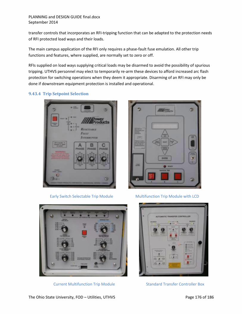
PLANNING and DESIGN GUIDE final.docx September 2014
The Ohio State University, FOD – Utilities, UTHVS Page 176 of 186
transfer controls that incorporates an RFI-tripping function that can be adapted to the protection needs
of RFI protected load ways and their loads.
The main campus application of the RFI only requires a phase-fault fuse emulation. All other trip
functions and features, where supplied, are normally set to zero or off.
RFIs supplied on load ways supplying critical loads may be disarmed to avoid the possibility of spurious
tripping. UTHVS personnel may elect to temporarily re-arm these devices to afford increased arc flash
protection for switching operations when they deem it appropriate. Disarming of an RFI may only be
done if downstream equipment protection is installed and operational.
9.43.4 Trip Setpoint Selection
Early Switch Selectable Trip Module Multifunction Trip Module with LCD
Current Multifunction Trip Module Standard Transfer Controller Box
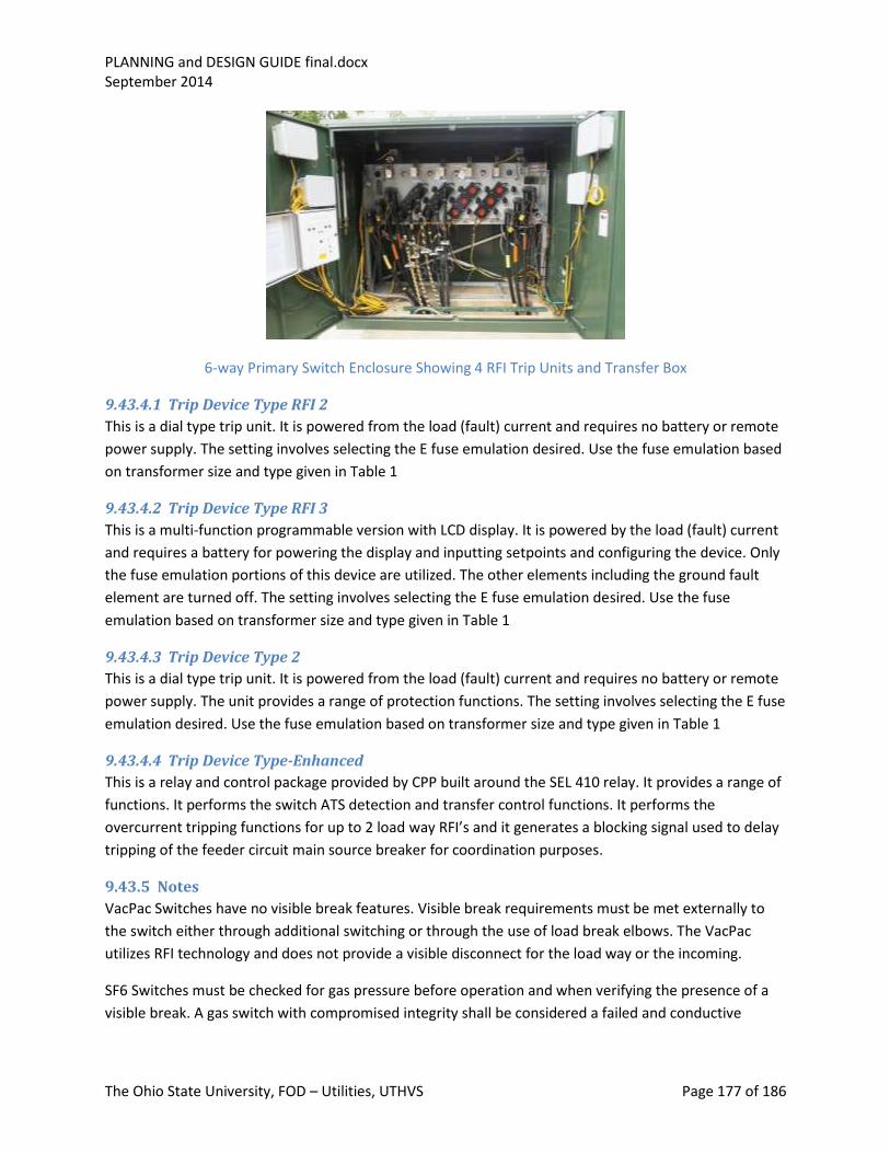
PLANNING and DESIGN GUIDE final.docx September 2014
The Ohio State University, FOD – Utilities, UTHVS Page 177 of 186
6-way Primary Switch Enclosure Showing 4 RFI Trip Units and Transfer Box
9.43.4.1 Trip Device Type RFI 2
This is a dial type trip unit. It is powered from the load (fault) current and requires no battery or remote
power supply. The setting involves selecting the E fuse emulation desired. Use the fuse emulation based
on transformer size and type given in Table 1
9.43.4.2 Trip Device Type RFI 3
This is a multi-function programmable version with LCD display. It is powered by the load (fault) current
and requires a battery for powering the display and inputting setpoints and configuring the device. Only
the fuse emulation portions of this device are utilized. The other elements including the ground fault
element are turned off. The setting involves selecting the E fuse emulation desired. Use the fuse
emulation based on transformer size and type given in Table 1
9.43.4.3 Trip Device Type 2
This is a dial type trip unit. It is powered from the load (fault) current and requires no battery or remote
power supply. The unit provides a range of protection functions. The setting involves selecting the E fuse
emulation desired. Use the fuse emulation based on transformer size and type given in Table 1
9.43.4.4 Trip Device Type-Enhanced
This is a relay and control package provided by CPP built around the SEL 410 relay. It provides a range of
functions. It performs the switch ATS detection and transfer control functions. It performs the
overcurrent tripping functions for up to 2 load way RFI’s and it generates a blocking signal used to delay
tripping of the feeder circuit main source breaker for coordination purposes.
9.43.5 Notes
VacPac Switches have no visible break features. Visible break requirements must be met externally to
the switch either through additional switching or through the use of load break elbows. The VacPac
utilizes RFI technology and does not provide a visible disconnect for the load way or the incoming.
SF6 Switches must be checked for gas pressure before operation and when verifying the presence of a
visible break. A gas switch with compromised integrity shall be considered a failed and conductive
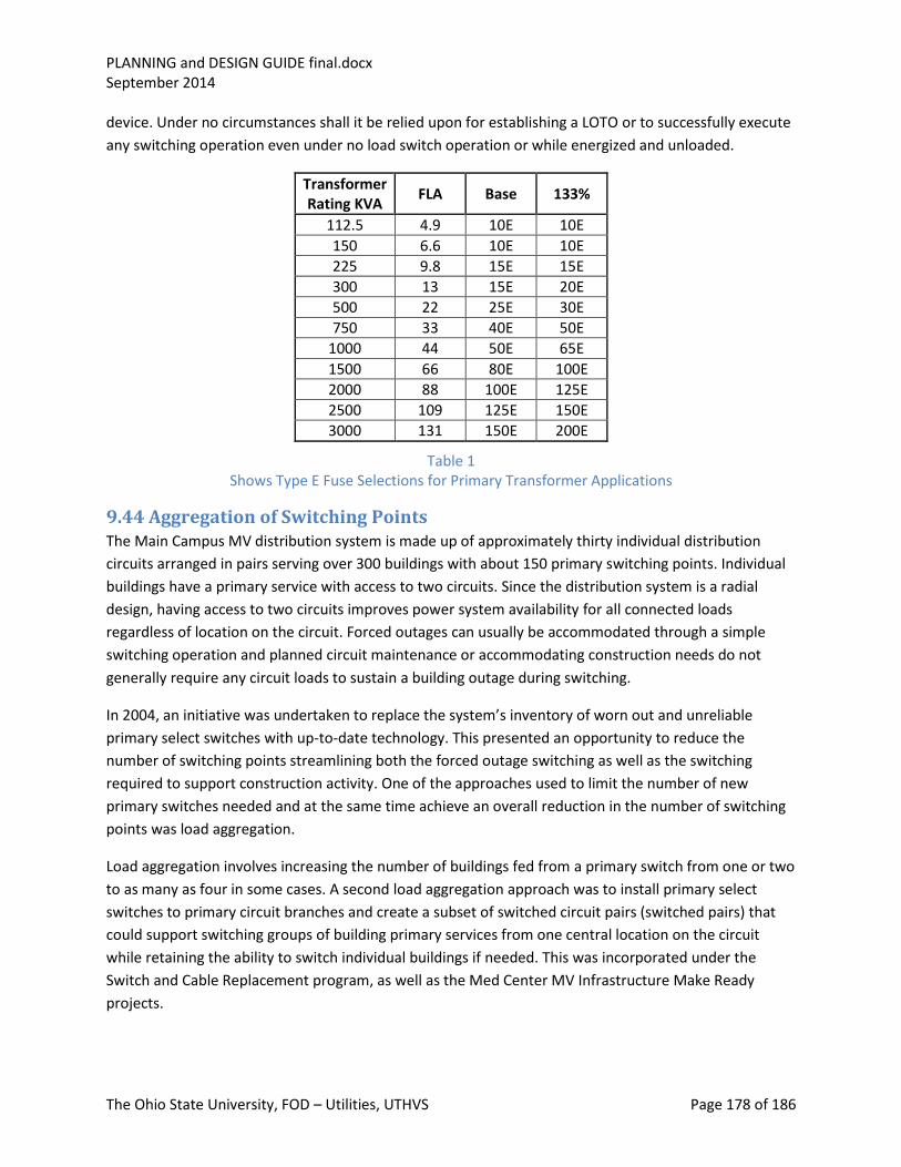
PLANNING and DESIGN GUIDE final.docx September 2014
The Ohio State University, FOD – Utilities, UTHVS Page 178 of 186
device. Under no circumstances shall it be relied upon for establishing a LOTO or to successfully execute
any switching operation even under no load switch operation or while energized and unloaded.
Transformer Rating KVA
FLA Base 133%
112.5 4.9 10E 10E
150 6.6 10E 10E
225 9.8 15E 15E
300 13 15E 20E
500 22 25E 30E
750 33 40E 50E
1000 44 50E 65E
1500 66 80E 100E
2000 88 100E 125E
2500 109 125E 150E
3000 131 150E 200E
Table 1 Shows Type E Fuse Selections for Primary Transformer Applications
9.44 Aggregation of Switching Points The Main Campus MV distribution system is made up of approximately thirty individual distribution
circuits arranged in pairs serving over 300 buildings with about 150 primary switching points. Individual
buildings have a primary service with access to two circuits. Since the distribution system is a radial
design, having access to two circuits improves power system availability for all connected loads
regardless of location on the circuit. Forced outages can usually be accommodated through a simple
switching operation and planned circuit maintenance or accommodating construction needs do not
generally require any circuit loads to sustain a building outage during switching.
In 2004, an initiative was undertaken to replace the system’s inventory of worn out and unreliable
primary select switches with up-to-date technology. This presented an opportunity to reduce the
number of switching points streamlining both the forced outage switching as well as the switching
required to support construction activity. One of the approaches used to limit the number of new
primary switches needed and at the same time achieve an overall reduction in the number of switching
points was load aggregation.
Load aggregation involves increasing the number of buildings fed from a primary switch from one or two
to as many as four in some cases. A second load aggregation approach was to install primary select
switches to primary circuit branches and create a subset of switched circuit pairs (switched pairs) that
could support switching groups of building primary services from one central location on the circuit
while retaining the ability to switch individual buildings if needed. This was incorporated under the
Switch and Cable Replacement program, as well as the Med Center MV Infrastructure Make Ready
projects.
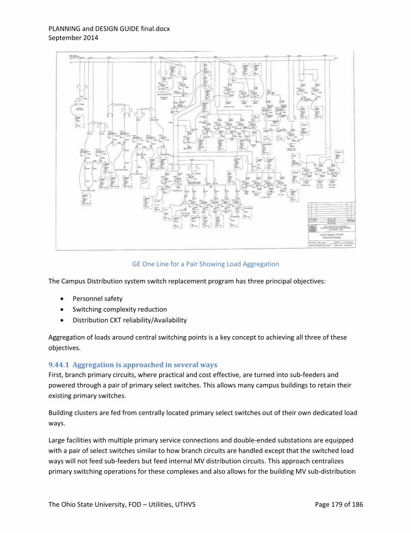
PLANNING and DESIGN GUIDE final.docx September 2014
The Ohio State University, FOD – Utilities, UTHVS Page 179 of 186
GE One Line for a Pair Showing Load Aggregation
The Campus Distribution system switch replacement program has three principal objectives:
Personnel safety
Switching complexity reduction
Distribution CKT reliability/Availability
Aggregation of loads around central switching points is a key concept to achieving all three of these
objectives.
9.44.1 Aggregation is approached in several ways
First, branch primary circuits, where practical and cost effective, are turned into sub-feeders and
powered through a pair of primary select switches. This allows many campus buildings to retain their
existing primary switches.
Building clusters are fed from centrally located primary select switches out of their own dedicated load
ways.
Large facilities with multiple primary service connections and double-ended substations are equipped
with a pair of select switches similar to how branch circuits are handled except that the switched load
ways will not feed sub-feeders but feed internal MV distribution circuits. This approach centralizes
primary switching operations for these complexes and also allows for the building MV sub-distribution

PLANNING and DESIGN GUIDE final.docx September 2014
The Ohio State University, FOD – Utilities, UTHVS Page 180 of 186
to add additional switching flexibility and the ability to work on or replace distribution components
while maintaining full service.
Personnel safety is served by achieving a dramatic reduction in the number of switching operations
required to transfer building feeds and clear faulted feeders.
Switching complexity is reduced by limiting the number of switched points, providing a high level of
standardization and making all switching points accessible without the need to obtain keys to gain
access to campus buildings.
Reliability/Availability is addressed by reducing the number of buildings directly impacted by a circuit
failure (switch or cable), facilitating automatic transfer of buildings powered from sub-feeder circuits,
and shortening the time required to isolate and repair failures.
9.44.2 Hardware
The principal component in the aggregation will be the SF6 gas load interrupter switch.
In its application as a building service primary select switch, it provides a safe and reliable switching
point for the building supply with load ways equipped either with RFIs, fused elbows and/or load break
(isolation) switches determined by the personnel and equipment protection needs of the specific
installation.
In its application as a circuit switching point for branch circuits, a pair of SF6 switches, configured to be
fed from three primary circuits (2 mains and a standby or “swing” feeder), power a pair of sub-feeders.
Load ways of these switches are supplied with RFIs and protective relays set to isolate sub-feeder faults
and limit their effects to a minimum of other campus buildings. The other use for the RFI is to provide
upstream tripping for load ways with personnel exposure such as exists at high-side primary fused
disconnect switches. While the RFI operation will not generally coordinate with the upstream feeder
source CB, it will be faster to interrupt and thereby reduce the arc flash level at the fused disconnect.
The incoming load break switches are equipped to automatically transfer so that, in the event of a loss
of primary feeder, the sub-circuit would be automatically transferred to the stand-by or “swing “ feeder.
9.44.3 Protection
Primary protection for the Building Service (Primary) Transformers is provided by the application of
suitably rated E type power fuses. The standard feeder protection package consists of a protective relay
with an inverse time overcurrent characteristic for phase and ground faults along with a definite time
relay element for phase and ground faults in excess of 4800 and 3200 Amps respectively. Backup
protection is afforded by the main substation buss feeder circuit breaker overcurrent relays. The feeder
protection is set to coordinate with the approved fusing for primary transformers up to and including
2500 kVA. Applications installing primary transformers larger than 2500 kVA and applications that
require feeder circuit CB coordination with a downstream CB (RFI), require the application of the
Enhanced Relay Package to retain coordination.

PLANNING and DESIGN GUIDE final.docx September 2014
The Ohio State University, FOD – Utilities, UTHVS Page 181 of 186
The feeder protection described above is applied both to circuit feeders and third feeders. The only
difference in the settings for circuit feeders and third feeders is in the choice of CT ratio and relay
pickup. Feeder circuits have an 800 A pickup and operate off the 800 to 5-tap on the breaker CT’s. Third
feeders have a 1200 Amp pickup and operate off the 1200 to 5-tap of the breaker CT’s. This
accommodation reflects the fact that third feeder loadings can approach 800 Amps under emergency
loading conditions.
In instances where individual building services have the primary select switch upgraded to a CPP SF6 gas
switch, the new switch will be provided with an RFI load way if:
1. The primary transformer has a functional fused indoor load break switch, or 2. The existing primary switch will be retained and used as a fused disconnect and LOTO point for
the service. The new switch will be provided with a load interrupter load way if: There is no fused air break switch being provided and hence no acceptable LOTO point with visible
disconnect. In this case, a fuse cabinet or in-line fuses (fused elbows) are provided, and the primary
switch will serve as the LOTO point. If fused load break elbows are applied, the primary switch need not
be relied upon to establish a visible break, but the break can be at the load break elbow.
9.44.4 Enhanced Relay Protection System
An enhancement is being added as part of the Switch and Cable Replacement Project that will allow
selected facilities to install primary transformers greater than 2500 kVA and provide selectivity for
tripping off faulted branch circuits from a feeder. The enhanced relay protection system uses fiber optics
to block or delay circuit feeders tripping for faults beyond the primary select switch. It also affords
backup protection for the primary switch relaying. The system consists of an enhanced relay package
mounted at the primary switch with fiber communications back to the source substation where a logic
processing unit communicates to the appropriate source circuit breakers. The system also has a
supervisory system which monitors the primary switch status for incoming ways, load ways, ATS
function and equipment status alarming. With this system in place, sub-feeders are protected by RFIs in
the new branch circuit switches. Fault-clearing times are comparable to that already provided on
primary feeders (160 ms for design level faults). Back-up protection is provided by the protective
relaying applied to the source feeder.
Feeder protection provides fault-clearing times approximately equal to what is presently achieved with
the Siemens 50/51 TOC and hi-set relaying but with an additional ride-through feature that allows faults
sensed by the branch circuit switch’s RFI’s to be cleared by the RFI, allowing the remainder of the
primary feeder to remain in service.
The introduction of the dual switches and third feeders on the OSU MV distribution system also
necessitated the upgrade of street feeder protection and the addition of limited system supervisory
communications. Because the dual switch applications serve a variety of purposes, not all will require
the feeder relaying and supervisory upgrade.

PLANNING and DESIGN GUIDE final.docx September 2014
The Ohio State University, FOD – Utilities, UTHVS Page 182 of 186
Dual primary switch installations fall into the following broad classifications:
1. Dual switches that supply switched pairs or branches off main circuit pairs where the main
circuits serve high priority loads but the branch does not.
2. Dual switches that supply switched pairs or branches off main circuit pairs where the main
circuits and the branch circuits serve high priority loads.
3. Dual switches that supply buildings such as the Medical Center complexes where there is an
internal MV distribution of high priority loads.
4. Dual switches that supply switched pairs or branches off main circuits where the main circuits
do not serve priority loads.
5. Dual switches where the protection applied to the load served will not coordinate with the main
feeder protection original high set relay functions (East Regional Chiller Plant)
This diversity of applications are the result of the fact that the third feeder/dual switch design is
intended to meet a variety of system needs relating to, not only fault clearing speed and coordination,
but also increased switching efficiency, circuit loadability and power availability and reliability.
Relaying enhancement:
For select dual primary switches we are applying an enhanced protective relay package that replaces the
standard CPP RFI trip devices. This package will detect faults downstream of the dual switches and
isolate the faulted branch circuit or load. At the same time it acts to isolate the faulted branch circuit or
load, it will send a blocking signal to the upstream main feeder CB over current relaying, instructing it to
delay reacting to the fault current for a sufficient time to allow the downstream RFI to clear the fault. In
addition, the system will provide the intelligence to detect a failed switch or RFI failure to successfully
trip and take the appropriate actions including alarming and blocking primary switch transfer.
Enhanced Supervisory:
In the first phase of HV S&C Phase 2, we will gather some limited system status information for hand off
to the existing ION system using the enhanced protective relay platform. This information covers limited
information on switch and RFI status on dual switches equipped with the enhanced protection package.
Eventually, the plan is to have the supervisory functions expanded to include load monitoring and
automated supervision of primary switch transfers using a state of the art automated dispatch platform.
Dual switches that supply switched pairs or branches off main circuit pairs where the main circuits serve
high-priority loads but the branch does not:
These installations will be equipped with the enhanced relaying. The relaying will make it possible to get
selectivity through main CB RFI coordination, avoiding a fault in or on a switched pair from unnecessarily
tripping the main feeder supplying high priority services there by limiting the number of services
impacted by a branch circuit fault.
Dual switches that supply switched pairs or branches off main circuit pairs where the main circuits and
the branch circuits serve high priority loads:

PLANNING and DESIGN GUIDE final.docx September 2014
The Ohio State University, FOD – Utilities, UTHVS Page 183 of 186
Generally these will be equipped with the enhanced relaying. However, the relative level of exposure
represented by the individual facilities’ switched primaries may influence the decision to apply the
additional relaying to that facilities’ primary service.
Dual switches that supply buildings such as the Medical Center complexes where there is an internal MV
distribution of high priority loads:
This classification is somewhat redundant to the above two but is common and is included here for
discussion. Usually these internal switched primaries power matched sets of fused air break switches
powering transformers which, in many cases feed double-ended substations. While the installation is
indoor and in conduit, there may still be a significant amount of exposure present. There needs to be a
comparative evaluation of the relative risk to overall reliability from air break switch circuit faults vs,
false tripping of the RFIs.
Dual switches that supply switched pairs or branches off main circuits where the main circuits do not
serve priority loads:
Generally these will not be equipped with enhanced protection, as the risk of false tripping is not
counterbalanced by any advantage to be gained. In such cases, the original CPP FRI tripping package
may be retained and the RFI disabled during normal operation and re-armed only when the air breaks
are being switched. Consideration may be given to keeping RFI trips in service for possible coordination
benefits for low current faults.
Dual switches where the protection applied to the load served will not coordinate with the main feeder
protection original high set relay functions (East Regional Chiller Plant)
These will be equipped with the enhanced protection to insure coordination for transformer faults
where the fusing alone would not provide coordination and selectivity.
Load ways off dual switches where the load way feeds do not feed branches and there is fuse relay
coordination do not require a relayed RFI.
RFI Settings
Overview: Coordination and selectivity become an issue when RFIs power a switched primary or when
they power loads where the fusing will not coordinate with the short time settings of the main primary
feeder source beakers. This issue exists for both phase and ground relaying. The enhanced relaying
application is designed to address this issue.
Switched Pairs: An RFI feeding a switched pair circuit should have its relay set to coordinate with the
fuses in the transformer fused disconnects downstream of the dual switches feeding the switched
primaries. (This will be the case for primary transformers 2500 kVA or less.) The relay setting for this RFI
application should be the same as the phase and ground settings currently used for the primary source
breakers. This is a definite time high set (4800 A Phase, 3200 A ground, 30 ms delay), accompanied by a
time over current (800 A pu, 1.4 lever, very inverse time characteristic for Phase, 320 A pu, 0.6 lever

PLANNING and DESIGN GUIDE final.docx September 2014
The Ohio State University, FOD – Utilities, UTHVS Page 184 of 186
inverse time characteristic for ground). In addition, the relay should have instantaneous phase and
ground elements set substantially below the pick-up values for the definite time high set values in the
main feeder protection to provide a trip block signal with no intentional time delay. Reset for this
function should be programmed for between 4 to 6 cycles.
Uncoordinated Loads: An RFI feeding a load (one or more transformers, with or without fuses) where
the standard feeder breaker relay high set definite time elements settings will not coordinate, should
have their relays set to provide fault detection and where appropriate overload protection (damage
curve observance) while maintaining coordination with the secondary mains or equivalent low side
protection. In instances where transformer protection is afforded by fuses and the RFI has been set as a
back-up or supplement for arc fault protection and coordination between the transformer protection
and the main feeder breaker doesn’t exist, the RFI relay setting should be set to afford the best backup
to the transformer protection while observing a reasonable margin. Coordination between fuse and RFI
should not be attempted unless there are multiple fused transformers fed from the same load way RFI.
In addition, the relay should have instantaneous phase and ground elements set substantially below the
pick-up values for the definite time high set values in the main feeder protection, programmed to
provide a trip block signal. Reset for this function should be programmed for between 4 to 6 cycles.
Main Feeder Settings
Overview: Main feeders can be either primary pair feeders or third feeders. The only difference in their
relay setting strategy is in the pick-up values applied to the inverse time phase over current functions.
Primary pair pick-up settings are at 800 A, third feeders are at 1200 A reflecting their higher potential
loading (600/750 A vs. 400 A)
Basic: The basic protection is afforded by phase and ground high set definite time and inverse time over
current functions. This is the basic setting strategy applied to all circuit pairs that have complete load
protection/main feeder coordination and do not employ the enhanced relaying.
Supervised: In the enhanced application, the high set phase and ground functions in the basic
protection scheme are supervised by an enabling mirrored bit that communicates to the relay that the
enhanced relaying system is not operational.
A second set of phase and ground high set definite time functions set to the same pick-up values as the
basic but delayed (2 cycles) are provided to trip the appropriate feeder breaker conditional on the
absence of a blocking mirrored bit from the enhanced relaying system.
A third set of phase and ground high set definite time trip functions set to the same pick-up values as
the basic but delayed an appropriate coordination time (12 cycles) are provided to trip the feeder
breaker independent of any permissive or blocking mirrored bits received by the relay. This third set
provides an effective breaker failure oversight of the downstream RFI should it fail to trip or fail to
interrupt fault current.
PLANNING and DESIGN GUIDE final.docx September 2014
The Ohio State University, FOD – Utilities, UTHVS Page 185 of 186
Default: The basic feeder protection afforded the distribution system presently will be retained (no
additional delay) with the enhanced relaying system under conditions where the enhanced system is
inoperable or impaired; communications between the feeder CB and the system fails.
With the system operational, primary protection for switched pairs and dual switch primary services
with enhanced relaying is unchanged from current protection reaction and clearing times. With the
system operational, fault detection and clearing on the main feeders will be delayed for high current
faults by 2 cycles rather than 12 cycles as would have to be the case to obtain coordination without the
enhanced relaying.
In the event that an RFI fails to trip or interrupt, the relay will act to trip the source breaker in 12 cycles,
longer than the time the feeder would have relayed off had there been no enhanced relay package.
However this extended fault duration would only be experienced for a failure of an RFI to trip, a low
probability event compared to others that would require fault detection and clearing.
Enhanced Relaying Advantages
Distribution system enhanced relay protection performance can provide selectivity and coordination
without any significant degradation in fault detection and clearing time. Current fault damage and arc
fault levels are essentially maintained at current levels with improved circuit availability through
enhanced selectivity. A loss of the enhanced relaying functionality returns the distribution system
protection to original, pre-enhancement performance expectations with a very minor or no impact on
detection and fault clearing times.
9.45 Utility Communications System The medium voltage distribution system and associated substations do not permit the use of remote
supervisory control for security reasons. There is however a data acquisition system referred to as the
Utility Communications System (UCS). Its hardware and software base is in the ION metering system and
is relied upon to report the status of key substation components as well as a limited number of
distribution system field devices. It also is used as a vehicle for collecting feeder and system
instantaneous and trending load data and displaying waveform data for analyzing system disturbances.
Equipment status monitoring is provided for all active circuit feeder source breakers for both manual
switching and more significantly for automatic tripping via protective relay actuation. West Campus Sub
and OSU Sub have self-contained annunciator systems that provide local displays and also interface with
the UCS to provide equipment operating status and convey critical maintenance alarming to UTHVS
staff. Out on the distribution circuits where the new enhanced relaying is being applied, primary and
load way switch status will also be reported back to the UCS.
System metering data is obtained from ION based metering mounted on the substation main busses as
is buss voltage. These meters log circuit parameters on a regular (15 min) interval and provide a
historical record of KVA, voltage, phase currents, power factor, power quality and a range of related
data on the operation of the metered device. Main feeder ION meters also are capable of wave form
storage for system events and can be used to diagnose system failures and transients.
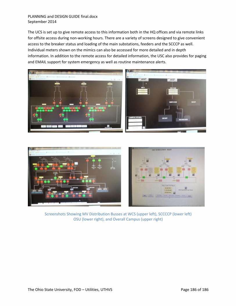
PLANNING and DESIGN GUIDE final.docx September 2014
The Ohio State University, FOD – Utilities, UTHVS Page 186 of 186
The UCS is set up to give remote access to this information both in the HQ offices and via remote links
for offsite access during non-working hours. There are a variety of screens designed to give convenient
access to the breaker status and loading of the main substations, feeders and the SCCCP as well.
Individual meters shown on the mimics can also be accessed for more detailed and in depth
information. In addition to the remote access for detailed information, the USC also provides for paging
and EMAIL support for system emergency as well as routine maintenance alerts.
Screenshots Showing MV Distribution Busses at WCS (upper left), SCCCCP (lower left) OSU (lower right), and Overall Campus (upper right)