electrical measurements and their industrial … type igll-a capacitance test bridge. ... the new...
TRANSCRIPT

'" z: C>
Ico: c..>
..... .... .... co: ..... co:
'"' ..... V')
::::> Q
z:
'"' ... :z: I-
Q
z: co: V') ..... z: ... ~ ... '"' ::::> V')
co: ... ~
..... co: c..>
VOLUME XXIII No. 2 JULY , 1948 Co p yright, 1941, G. n . ral Ra d io Comp"ny. C ......... ldg., Man., U. S. A .
A WIDE-RANGE CAPACITANCE TEST BRIDGE
IN THIS I S SUE
Page ~IU:lC t: I,L"'NY , .. S
to one. O\'cr this entire maintained.
• WIDE- RANGE is a term that has no absolute meaning and is pCl'haps used a bit loosely on occasions in technical and promotional writing. Nevertheless, there is little r'isk of criticism of its use to describe the TYPE IGll-A Capacitance Test Bridge. This new bridge measures capacitance from I /-lIAr to 10,000 /-If, a range of tell billion ra nge all accuracy of ±(l% + I J.I~) is
The fleW bridge combi nes the functions of the older TYPES 740-B· and 740- RC· but improves on the pcrfonmmce of each in se\'erai important respects. In accuracy, scn:silivity, and convenience the performaDce equals or exceeds that of both previous models. In the very important range below 1000 JAJAf, the performnnce has been markedly improved by the lise of a unique zero-eompensating circuit. For the me.'lSlIrement of electrolytic capncitors, the new bridge permits the application of a polarizing voltage from a grounded power su pply, an important convenience fen,ture. The scnsitivity of the detector is controlled by the bridge unbalance in such a manner that balance e!lll be re.1.chcd with a. min imum manipulation of the manual gain controL
The panel controls and their location h:l.ve been selected with ease of opm'ation in mind. Thc lcss+uscd controls are near the top of the panel, the more used near the bottom where they are most accessible.
The scales of the capacitance and di;..si pnl ion facto r dials are direct read ing in capncitancc and di!';sipation factor, and t he indexes for both scales are visible thl'Ough a ~ingle Will dow. Since at the index both scales are vcl1ical, both increase upward. Hence in creasing readings nre obtained fot' COllnterciockwi.<;e l"otution of the right+h::md knob, and ror clockwil"e rotal ion of the icft~hnnd knob.
' Alth"UjI:;h Ih" ·r .... ~ 74()..BO earaeita""" T ... t Rridge hu been didoonHnu.d. the THE 74()..]t i~~liU .,·ail.hle. l~ limited field 0 useruln_ .... co",pared to th .. """. ];>';<1, •• ;8 "f(Bet by he lo"'er priee.
IET LABS, Inc in the GenRad tradition
534 Main Street, Westbury, NY 11590 www.ietlabs.com
TEL: (516) 334-5959 • (800) 899-8438 • FAX: (516) 334-5988
GENERAl RADIO EXPERIMENTER
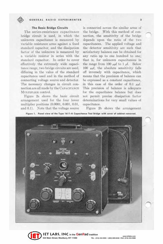
The Basic Bridge Circuits The series-resistance capacil a nce
bridge circuit is used , in which the unknown capacitance is measmed by variable resistance arms against a fixed standard capacitor, and the dissi pation factor of the unknown is measured by a variable resistor in series with the standard capacitor. ]n order to cover effectively the cxtremely wiele capacitance range, two bridge circuits are tlsed, differing in the value of the standard capacitance used and in the method of connecting voltage source and detector. The necessary changes in circuit connection are fiJI made by the CAPACITANCE
MUI.TIPLl~;n control. Figure 2a shows the basic circuit
arrangement used for the fotlr lower multiplier positions (0.0001 , 0.001 , 0.01, and 0.1). Note that the voltage source
, is con nected across the similar arms of the bridge. Wi th this method of connection, the sensitivity of the bl'idge depends upon the ratio of the two capacitances. The applied voltage and the detector sensitivity arc stich lIw.t satisfactory balance can be obtained r or any ralio up to one hundred to one; that is, for unknown capacitances in the rnnge from 100 ~JJf to 1 JJf. Below 100 JJ~f, the absolute sensitivity falls off inversely with capacitance, which means that t he prccision of balance ca n be expressed as a constant capacita nce, in this case of the order of 0.1 ~~f. Th is precision of balance is adequate for the ca pacitance balance but does not permit pl'CCise dissipn.tion factor detcrminations for very small values of capacitn nce.
Figure 2b shows the ur l'angement
IET LABS, Inc in the GenRad tradition
534 Main Street, Westbury, NY 11590 www.ietlabs.com
TEL: (516) 334-5959 • (800) 899-8438 • FAX: (516) 334-5988

,
used fo r the fou r higher multipliers (10, 100, 1000, lind 10,000). Note that t he voltage source find the detector h11\'O 1)C('1l interchanged as com pnred to the ci rcui t. of F igure 21\ , nnd tha t. the c!lpncihmcc of the stundnrd lHln
has 1)C('11 cha nged from 0.01 ~f to 1.0 /.If. III this method of conncction the bridge S<'lIsitivity is :l. fUllction of the m lio of the n.·", i"t:l.ncc R.~ to the im rx'{ia ncl.' in the !St:lndurd arm. l ' nlikc the circuit of Figun\ 2.'1, the sensitivit.y of the ci rcuit in Figure 2b docs not. change IIR
the ratio :\I'm Nil is changed . Optimum scnsitivity would be aHained with the impc<itlllC'C of the standard finn equal to the resistance RA • The latter is vu riable, bowever, being the ba lnncing llfm
of the bridge, and, Rccordingi)" the scnsitivity vuries with the selli ng of this firm. 'fhe reactam:e of 11 ca p,'\citance of 1 jJ.f at 60 cycles is 2650 ohms, a nd maximum sensitivity is at.ta ined when the RA equals this vnlue. Actually the Illnin decade of the A-n rm rheostat ~(K'~ from 1000 to 10,000 ohms, 80 that the sensit ivity is optimum fit about mid-scllie and dUlnges relatively little over the runge.
Bridge Voltages l3ecallse of the very wide
input. imped ance presented rH nge of by the
fI _HA}{J •
•
•
JULY , 1941
(toh) figu .. 20. e ... I. b.ldgo c l.cu" ulod lor ,h. 'flU. low .. mUlllpU., po"itlo"" .
(Abo ... ) Flgu .. 2b. CI.cult lor tho lour high .. mul,lpU ... po,illon • .
bridge, no single SOU rce of voltage e!lIl be capable of efficiently supplying test voltage for all rHngcs. Idcrtlly (t separate source of proper imped tm ee and voltage might be provided for ench multiplier position, but nn excellent. compromise is obtained by prO\'iding four SCpRr3tc
sources, one for e;)ch 1xlir of the eight multiplier positions. For each prtir of positions, a rcsistnm:e is pl:lced betwccn the b" idgc and the volttlge f:ource such that. the s:t me power ia delivered to the bridge for e11l·h po.~it ion . The I"CCJllired vnllle of ]'('si><la ncc iii, of COUI"SC, the geomelric meall of lhe two \lu lucs of bridge impcdllllce. The vultages for the four SOUt"Cl'!'I Ilre!:iO dl()I';Cll that , with these series rct.i!:' l:lIlCCS, the m:lximum s:.lfe power is deli\'ercd to the bridge for :my sett ing of the multiplier. Figure:l shows schematica lly the nrrnngement. The proper source is sclcct(.'(1 by a switch mechanically connected to the switch thut controls the mu ltiplier nllio of the bridge.
The Detector The detector system consists of a
s.ingle stage of amplification and a n clectron-rny tube used as :l visual Dull indicator. The amplifier is made selcc· tive to the opernt.ing freqlLCIll'Y by a parallel resonunt. circuit. in the plnte
IET LABS, Inc in the GenRad tradition
534 Main Street, Westbury, NY 11590 www.ietlabs.com
TEL: (516) 334-5959 • (800) 899-8438 • FAX: (516) 334-5988
~ GENERAL RADIO E X PERIMENTER
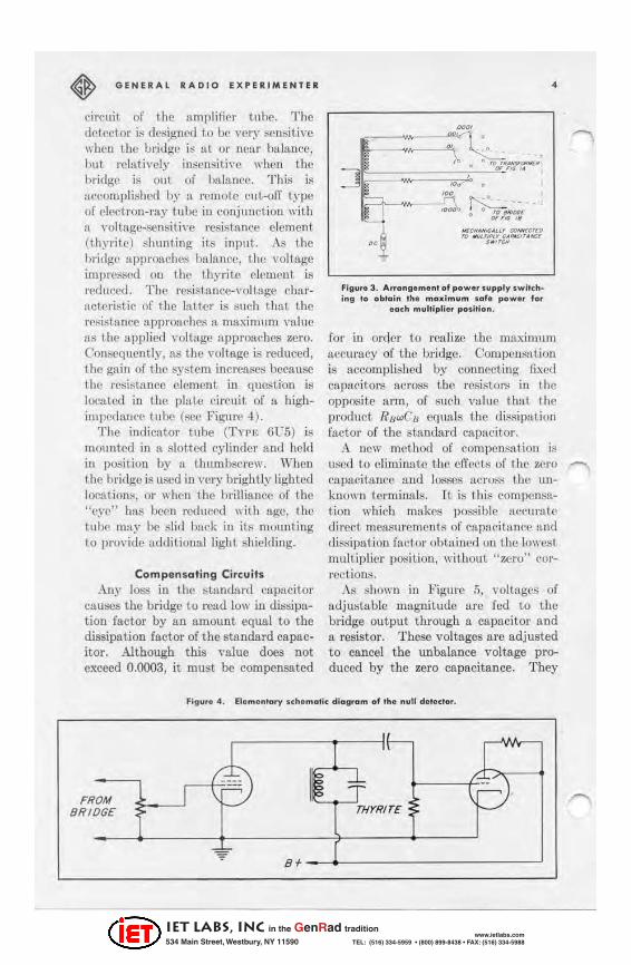
circuit. of the umplifif' 1' tube. The detector is designed t.o be very sensitive when the bridge is at 01' neul' buifl.tlce, but rclaiivcly in~cnsiti\'c WhCH the bridge is Ollt of balance. This is accornpli.-:llcd by a I'emote cut.-ofT type of clcdron-ray tube in conjunction with tL \'Qilagc-sensiti\'c l'e8i~tun{'e clement (thy ritc) ."hunting it.'" input. As the bridge approaches balance, the voltage impl'cs.';ed on the thyrite clement is I'educed. Th{' 1'(,f; i sttlncc- \'o1t~ll!;{' <: h1lrflclcristic of the !:"tHe!' is :;tIch that the resistance approllf'hc:'\ fl maximum \'alll!! fl.S tilt, applied \·olt:.lb"C a pproaches ZCI'O.
COIlM!CJucntly, :\8 til(' volttlge is reduced , the ga\1I of the iiiystem increases because the resistance element ill question is located in the plale circuit. of a highimJlNlanc~ lube (see Figure .1).
Thc indicator tube (TYPE (iUS) is mountoo ill It sloth.-d cylinder :\nd held ill pO:'!itiou by fl thumbSC l'Cw, When the bridge is lIRL-d in vory brightly lighted [o(;ations, Qt' when the briltiunce of the "eye" has been rcducC(i with age, the t ubo mily bo slid bUl'k in it ~ nlmml ing to provide addi t ioll[l[ light shielding,
Compensoting Circuits Any Joss in the ::,tlludurd capacitor
causes the bridge to roud [ow ill dissipation factor by an amount equal to the dissipation factor of the standard capacitor, Although this value does not exceed 0,0003, it mllst be compensated
~ I~ FROM I BRIDGE
~ " Bf
~"
~"==0,\~ , • '" r~._01'~,.' • """G" I , -.
Flgur, 3 . Arr"ng, m e nl of power s upply . wilch· ing 10 obtain th ' maximum . .. , _ P"W" f .. r
_a~h multlpll .. pOllllon .
•
for in oreiel' to rcalizc the maximum accurucy of the bridge. Compcnsntion is nccomplished by connecting fixed capneitors across t he resistor:; in the opposite arm, of :S llch value that the p!'OOLIct Rr1wC/J e(llInls the di~ilipation
fnctor of the standard capacitor, A new method of compensation is
113(.'(1 to elimi nate the effec t!,; of the zero capn(!itrmec and losses :1(:1'0&'1 the UIl
known terminllls, It is thili compensation which mnk<!s pO&lible tlCCUnitc
direct. me:)Slll'cnl(:nt ii of cltpacitancc Rod dis...;ipalioH fal'lor obtained on the 100\'c!S t multiplier pOf;ition , without " 7,cro" ('orrccl ioni>,
As shown in Figure 5, yollage::, of adjllst~ble magnitude are fed to the bridge output through a capacitor and a resistor, These voltages are adjusted to cancel the unbalance voltage produced by the zero capacitance, They
jf---
t 'P TH'I'RITE
IET LABS, Inc in the GenRad tradition
534 Main Street, Westbury, NY 11590 www.ietlabs.com
TEL: (516) 334-5959 • (800) 899-8438 • FAX: (516) 334-5988

,
Fig .... 5 . 5d •• mol;c d ia,.a m 01 circ uli .. led 10 c"nul II •• unbolonn ""itallt prod ..... d by th.
U ro «.pad lonn.
abo !«'r\-c to comlX'Ill)lltc p.'u,tinlly for u lly leukage through th(> bridge j r:msrunner li S well as for lilly small ,'ollage induced in the flmplificl" through l'ap:H'ilunce coupling to high-voltage leads.
T be t hl.'Ory lIpon which thi>l com· pCllsatillp: method is i):lAe(1 is as follows. Comiidcl' I h(' net work of Figul'(' 6 wlwre-
___ in II voltage E' is cou pled through an adrnitt ll ll('(' }' to to t he detector tf' l1ninft ls of the four-arm hridg{' network {'Ilergized by the \'ullage J5. T be f' nnd itioll of b.'1hm('{' (zem potcnti:li :lCrON> terminals.4 , I') iJ; rn ()'<; \ c:.u:i ly dNcrmined hy con,;idcrilll( I he !'hortl'irCl1it current a('r()t<l> the detector termiuaLs. The bridge itself produces :l current most convenicntly cxpressed in ndmittance form 115
. E Y'Y4 - Y2 Ys 1 .. - (1)
Yt + Yz + Ya + Y. The circuit E', Y.!> yields a current equal to E'l' 6' Equating the sum of the curren ts to zero Imd designating as a the ratio E' / E, we have the foUoll-jug expression:
)'1 V, - )'2V3 + aV.!>()'1 + } '2 + l'a + }'.) = 0 (2)
Fillu,. 6 , Equiv .. I .... ' dnuil .. I Ih bridll ... nd comp.nl ollnll ci •• .,II ,
JUL Y, 194 .
T lli,o; ca ll cOll vcniclllly be rcwritlCIl III the equiva lent form
0 '1 + a } '.!» ( l', + « 1'6) '""
0'2 - (IV.!» (1 ';1 - a r c;) (3) £qtmt ion ( ~ ) "lat!!>! that ill(' 111'1 work
of Figure 6 behaves:\t balance 1iIo; if an ntimitttlnCf1 a 1' r; were COIUlcctcd in pAmllcl wit h cflch arm, Of t hese fi ct ili ous admittancos, tll'O arc po"itiw' Iwd two ncgnti,'(' with til(' choice of ~ign
depending 0 11 the po!:lrity of the two \'oh».~s in volvl'd .
Rcfcningspt'ci fi cally to t he bl'idge network used in the 'I'"'I"'E 16 11 , it ii5 &len t hat. by prOI)C1' choiec of the rou pling admittance a nd t he voltage, un clTcctive /legalive cnpa('it3llce anu Ilega ti ve parnllel rcsist31ll'e arc produced IlCross the unknown term ina ls to ncutralize the rCIl! cilpacilance a nd re:;istallce t haL exist ther(l. Bimultaneously, the Slime
dTcctil'c capacitarwCl' lire pI:H:('d across t he :;tand:ml 1ll'Ill of the bridge, but. thl' circu it capacita nce thcl'c i:; 10,(0) p.p.f,
11n\l t he elTc'd , of thc introduced :ldmittnm'c i" for pr.wti!':!! PUl'p{)t;('s ncgligible, ,\ cross t il(> rc,.i1il:lIlce arm R." thcrc is all'io produ('cd an f'tTl'{'ti\"e ncga tinl capacitallt'c, Thi/'i 8('1'\'('S parti:l ll}' t o Il('Utl11l izc the relll l'llpacilnnce thut cxists acr&s this resistunce urm a nd to this extent improves further the accuracy of the circuit. Across the fourth arm B, the introduced capacitance is positive and would act to produce an error in
A
Y, Y,
E OEl
Y, Y. E'
A'
IET LABS, Inc in the GenRad tradition
534 Main Street, Westbury, NY 11590 www.ietlabs.com
TEL: (516) 334-5959 • (800) 899-8438 • FAX: (516) 334-5988

GENERAL RADIO EX PER IME NTER
dissipation fa.ctOl'; but, as has been pointed out Ilt'edously, cllp:lcitance is requi red tlCl"OSli this anll to ncutr:liize t he losses in the standard ca pacit.or. Therefore, in three of the four bridge arms, the clTect of the added circuit is ooncl1cial aod in t he fourt h arm it is negligible.
The compe.nsating circuit. is elTective for leakage through the bridge transformer and extmnCOllS pickup in the ampl ifier to the extent tha.t these ca o be re.presented by a voltage acting t hrough fl fixed impedftnce to t he amplifier iuput . All of the e~-traneous effects together with the deliberately introduced voltage a nd admittance ca o be combined and represented as in Figure 6.
The equations as written Mve been in terms of voltage impressed on tbe bridge cireu it, i.e., we have assumcd a zero--i rnpcdance generator. ActulI lly, of COUrRC, the m:lgllitude and phase of the voltnge impressed on the bridge cha nge as the bridge nrms [ire manipu. Inted, thus making I,he compensnt ioll less elicct ive. Fl ow{'\"cr , the Hhift of phl\~ a nd magnitude is not signific:lJ\t except, when t he caIXlcittlnce being mcaf'lJ 1"ed is so large thnt the zero efi(>cts ~lIld the stray pickups are inconsequential.
Circuit Ele ment, Several of the components used ill the
bridge, in order to realize the accumcy amI the direct,..]·cadillg features, fire a little unusual a nd are bdefly described.
As previously noted , two standard capaci tors are used, 0,01 ~f for the four low ronges nnd 1.0 ~f for the four high mllgcs. These afe specia l lIn it,s made lip using polystyrene t.apc for the insu lnling matm'ial. They are each mnde up of two units p.a.ired to y ield a t.otal c:lpacitance within ±0.25% of t be l.iesired value. The om ~f unit is
6
mounted in a 10\\·· los,<; phenolic cuse ns used for 'l'n>E 505 Cnpncitors. The -elements makillg up the 1.0 ~f unit arc hermetically scaled in cylilldrical metal contniners of the type commonly used for electrolytic c:lpacitors. Spccin l hcat treatment, aging. and im pregnation result in a st;)ndnrd of unusually high leakage resistance and tow dielectric losses.
T wo rheostats (one for each standa rd capacitor) Me lLSCd to b:ll:lnce the dissipation factor and nre gaoged to a common shaft. Each rheostat winding consists of twu tapered sections with the resistances of these sectioos so chosen that the resulting scale peL'mits precisc readinb'S at low values of dissipntion factor while at t he SIl.me t ime retaining the convenience of h:wing tho entire ra nge on ;) sillglc sca le, The stale is pre·engrnved and fOUl" adjustable shunt resistors fire provided , one across each ~ section of each rheostat to bring the ;)ctwd resistance in to agreement with the v:lhm re{luired by the sca le,
In some a pplications, as for instance in measuring many electrolytic cllpnci. tors in the range ]00)- 10,000 jAr, dissipation ractors in excess of 30% arc cncountered. For these \'a lues, provision is made in the bridge for swit ching into the Slllndnrd arm additional fi.xed resistors which extend the range to 60%.
The variable resistor Il.i' by mea ns of whicb the capacitance balance is ob· t:lined, is the same unit that haa been used prev iously in LhoU!;a nds of General Ihdio impedance and cnpaciUtnce bridges. It is:1- tapered rheostat having a totnl resistance of approximately 11 ,000 ohms with the t.aper so chosen that the scale of the dinl is essentiaUy loga.rithmic, An adjust ing plnte and ,.,......., cam are built into the unit, wh ich pennits an adj ustment of the position
IET LABS, Inc in the GenRad tradition
534 Main Street, Westbury, NY 11590 www.ietlabs.com
TEL: (516) 334-5959 • (800) 899-8438 • FAX: (516) 334-5988

7
of tbe ann with respect. to the dinl at. scl'ernl points. A." adjusted at. the factory, the resis\!lnoo in kilobms corn.-spolldl'. to the dial read ing within ±O.5% O,'cr the main decade from 1.0 to 10.
Applications This new bridge is suitable for use in
the electric power industry for the testing, in the shop, of the dissipation factor of bushings and insulators and of tbe insulation of electrical equipment. in general. 10 making measurements on such large, unshielded structures, voltages may be induced electrostatically which will shift the balance of the bridge . A switch is provided which permits reversing the test voltage with respect to the interfering voltage. The correct. capncitsncc and dissipation factor cun be computed from the two sets of readings taken for the two positions of t he switch. In most cases the calculation consists merely of tnking the arithmetic av('r-11g(' (If I h<: direct, !lnd reversc readillWi.
JULY, 194a
[n addition to its uscs for the testing of insulators and of components, the TYPE 1611-A Capacitulloo llridge should find wide applictl.I ion in chemical and plMlics laboratories for measuring the dissipation factor and dielectric constant of both so]jd Illld liquid dielectric m!ltcrials. The accuracy of dissipationf,lctor reading is adequate for aU but extremely low-loss materials such liS
polystyrene, mica, and good electrical grade ceramics. Even for these materials, Lbe dielectric constllnt can be evaluated accurately. It should be noted that the usefulness of electrica l tests of this kind is not lim ited to insulnting materinls. Increasing use is being found for electrical measurements 0 11 materials destined for uscs other than electrica l. P roduct control and the checking of batch-to-hatch uniformity of material on the b.'lslS of electrical coostani.s is one npplication that shows increasing promise of useruluess.
- I VAN O. BASTON
SP ECIFICATIONS CoPQcllonce 10n,.1 U I() 11,000 I'f, coverNI by eight multiplier sIep;! 1\1Id 1\/1 npl)TOximlltcly lognrilhmk, dircC't-rl'llding dial. Dlulpotlon_'octo.lon,el 0 to 00% (lit (j() cyclll!l ), ('O\'erro hy a dinl hs.ving lUI npl'T()XJmlltely logarithmic scale .... ith a rnngo of 301"'c, :lnt.! a IlI'o'[tl'lI that adds 1\ fixed value of 30% . Copodtonca Acc",.acy, ±(I % + I ...... 0 O\'er t he entltC mIlge of the bridge. Dlul,o,lon 'octo. Accu.ocy ' ± (2% of dial reading + 0.0.5 C'{. dissipation factm). Power F!I.O-
lor ,. ~lJ'" "here D .. dissiplLlioll factor.
Sen,I,lvltyl The "ensitivity is suuh that IUlY C'upacitnllce U! the rllflge 100 ""f to 10,000 J! f o.:lUl be bn['ITl~'f'(1 to 11 pfl!l;i.tion of M [eUljt 0. 1 '10. Tampa,o'"" . and Humidity I"e" " The rellding! of the brid.v:e lire ulIIlffected by temperfllilre and hUllHJily v!).rintiolllJ over the rBntl:c of room l'OndiliuliS Ilormslly cnl'Quntered (65° F to Me r·', 0 to 00% RH ). A_C Voltol . Applied to Copodtonc. "'ndor T .. t l The volt.'I4e III1P~ 011 t he un.1mo ..... n CllplwitlWl!e varies fT()m a mrucimum of approximately 125 voilA nl ]00 ...... f to 1_ thall a \'olu Rt T,,,.
16' I_A 1 Capacitance T .. t arldl • .
lO,OOO I'f. The ('inuit ill 80 nrrll.ngeJ thll~ h. lnllJ(imlllU of one volt-lI.mpere of rellctiv6 power is delivered to t he !JIlmpl!'. 1'010.ldnl Voltole, Terminahl Ilre provided for connecting an extenllli doe polurilillg vultage. The m!I.:"imum voltuge th!l~ I!hould be imprel:!!iOO is 5(X] .. 'OI~.
One of the terminnla ill grounded 110 that lUIy n-e uperated power 8upply with grounded out,)ut Clln be w,cd. The terminal C8pMitance<l of the po"'cr lIul)ply do not Ilfiect the bridge circuit. 'ower S",pply Voltale ' 105 to 125 (or 210 to 250 ) volt8, GO cycles. Pow • • 'nput, 15 Wlltts. AUDno.l .. Supplledl Lillc colilledur cord. Moun, lnl! Portable cllrrying efl:oC of luggagetype construction. CAAe III oorn"lctciy 8hielded to insure freedom from eleetll)jjtll.tie pickup. Vocu.,m T.,b. , . One each OX6-GT, 6SJ7, and 6US. All are Il:upplied. Het We1Ihfl 30'j 1101I11li8.
Dlmondon., (Width) 1 4t~ x (depth) lG ]I,'
(height) 10 inches, overall, Including cover lind IUllldles.
COth Word p~
.1 $375.00
IET LABS, Inc in the GenRad tradition
534 Main Street, Westbury, NY 11590 www.ietlabs.com
TEL: (516) 334-5959 • (800) 899-8438 • FAX: (516) 334-5988

GENERAL RAOIO EXPERIMENTER • MISCELLANY
V A CAT ION During the weeks
of July 26 and August 2 most of
Dill' employees will be vacationi ng. 11tl1l11facturing dcpnrlments will be
('Ioscd, a nd other de(Xlrlments will be manned by 11 skeleton stnfT. Every efTort \\·ill he mnde to take
carc of urgent busille"ll, but re
pairs callnot be made, except in hardship Ctlses. Our Service Departmcnt requests that. shipments of materia l to be rep:l iroo be either scheduled to reach us well before t.his vacntion period or delayed until afterward.
TE C HNI CAL PAP E R - " Evll luulion of I lysteresis Core Loss hy Power Equations," by T-i onltio W. Lamson, at the 19-18 Annual Meeting of the America n Society for Testing 1\ tutel'illis, Detroit, JUlie 22.
RECENT VISITORS to our plaut and laboratories include -
J . L. Tora, Instructor in Eleetricul Enginccring, I. C. A. I. , Madrid; J o!:c .tH. Rubinlo, Assistant. ProfCll .. or, University of 1\[adl'id; gugcnio Mendez, Instruetor, E. S. I. 1\1. E. , of ). rcxico, D. F .; and P. R. Dcsikocha r, Enginccr, All-Lndia H:l(lio. Bllugn lorc.
TilE General Radio EXI'ERIMEN1'ER U mailed «Iit.hou.t. churlle eoell 1II0nt.l. to engineers, "cientist&, tecltnicinn&, and otllers interested in
com,,,unicotion-/requency meaaure"lent lind control problenls. Wilen sending reque"t" for sub"cript.ions orld address-change noLice .. , plea .. e .. upply t.he/ollowing in/ormaLion: flame, company addre ..... type 0/ busine .... company i& e'lgaged in, and title or posi.tion 0/ individual.
GENERAL RADIO COMPANY 215 MASSACHUSETTS AVENUE
CAMBRIOGEU MASSACHUSETTS
M(W lOll I, II(W YOll II WfiT nun
TH. - WIITH !·un
TELEPHONE: TROWBRIDGE 4400
BRANCH ENGINEERING OFFICES LOS UGHU H . ULlfUNIJ.
151 MOUH ItIUlANO nuU( TEl. - HOLUWOOO UII
tHICAlG I, IlllMOIS UI SODTH MICHIUM AUIIU(
TEl.- WAIASH ,.21
IET LABS, Inc in the GenRad tradition
534 Main Street, Westbury, NY 11590 www.ietlabs.com
TEL: (516) 334-5959 • (800) 899-8438 • FAX: (516) 334-5988