electric motor performance improvement techniques · electric motor performance ... previous...
TRANSCRIPT
ORNL is managed by UT-Battelle for the US Department of Energy
Electric Motor Performance Improvement Techniques
Lixin TangEmail: [email protected]: 865-946-1526
This presentation does not contain any proprietary, confidential, or otherwise restricted information
2016 U.S. DOE Vehicle Technologies Office Review
Oak Ridge National Laboratory
June 7 , 2016 Project ID: EDT071
2
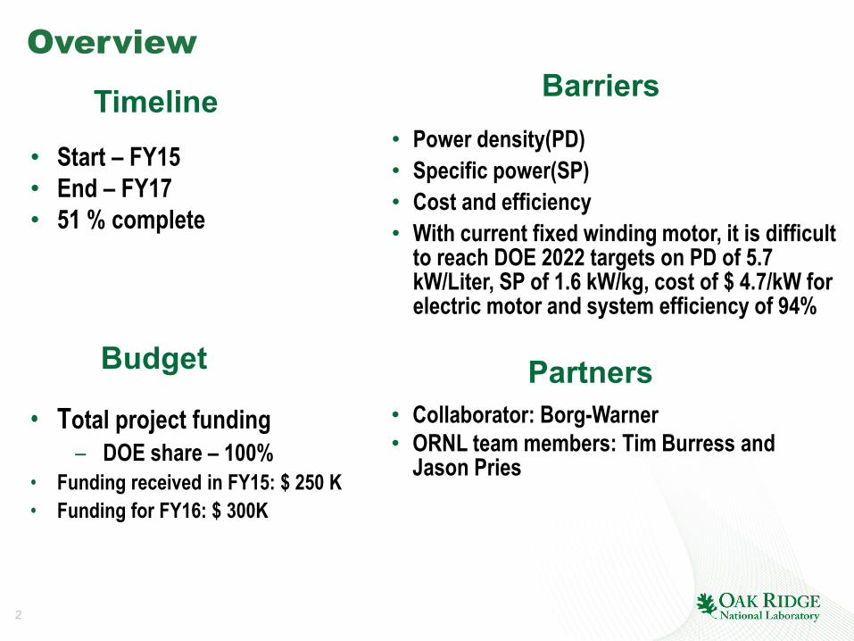
Overview
• Start – FY15• End – FY17• 51 % complete
• Power density(PD)• Specific power(SP) • Cost and efficiency• With current fixed winding motor, it is difficult
to reach DOE 2022 targets on PD of 5.7 kW/Liter, SP of 1.6 kW/kg, cost of $ 4.7/kW for electric motor and system efficiency of 94%
• Total project funding– DOE share – 100%
• Funding received in FY15: $ 250 K• Funding for FY16: $ 300K
Timeline
Budget
Barriers
Partners• Collaborator: Borg-Warner• ORNL team members: Tim Burress and
Jason Pries
3
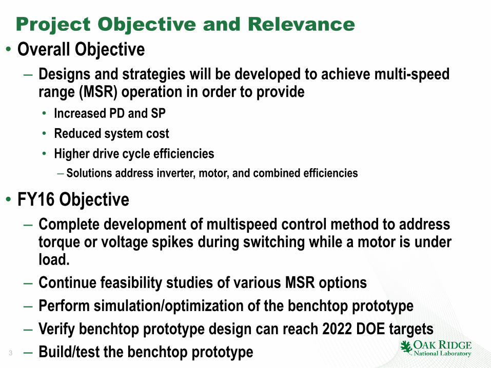
Project Objective and Relevance• Overall Objective
– Designs and strategies will be developed to achieve multi-speed range (MSR) operation in order to provide• Increased PD and SP• Reduced system cost• Higher drive cycle efficiencies
– Solutions address inverter, motor, and combined efficiencies
• FY16 Objective – Complete development of multispeed control method to address
torque or voltage spikes during switching while a motor is under load.
– Continue feasibility studies of various MSR options– Perform simulation/optimization of the benchtop prototype– Verify benchtop prototype design can reach 2022 DOE targets– Build/test the benchtop prototype
4
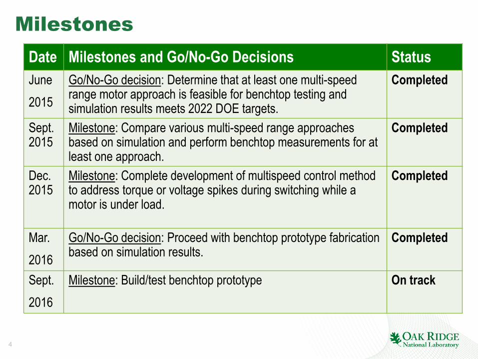
Milestones Date Milestones and Go/No-Go Decisions StatusJune2015
Go/No-Go decision: Determine that at least one multi-speed range motor approach is feasible for benchtop testing and simulation results meets 2022 DOE targets.
Completed
Sept.2015
Milestone: Compare various multi-speed range approaches based on simulation and perform benchtop measurements for at least one approach.
Completed
Dec. 2015
Milestone: Complete development of multispeed control method to address torque or voltage spikes during switching while a motor is under load.
Completed
Mar.2016
Go/No-Go decision: Proceed with benchtop prototype fabrication based on simulation results.
Completed
Sept.2016
Milestone: Build/test benchtop prototype On track

5
Approach/Strategy• Use MSR approaches to accomplish higher PD, SP, lower cost and
higher drive cycle efficiency through innovations in– Electric motor designs– Winding arrangements (e.g. reconfigurable windings)– Power electronics integration– Control techniques
• The major goal of this research is to increase the motor PD and SP by at least 25% compared to that of the state-of-the-art (SOA).
• A MSR approach can facilitate similar performance profiles with a smaller motor, thereby reducing volume/weight/cost.
• Previous approaches focus on expanding speed range of induction motor or surface permanent magnet synchronous motor drives, most of them are not for automotive powertrain applications.
6
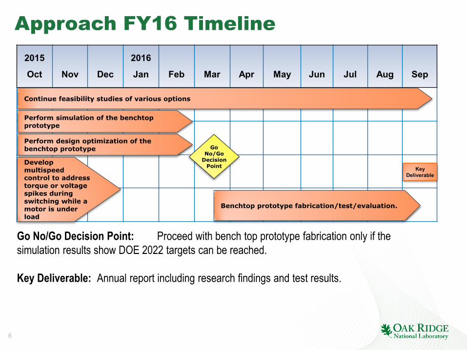
Approach FY16 Timeline2015
Oct Nov Dec
2016
Jan Feb Mar Apr May Jun Jul Aug Sep
Go No/Go Decision Point: Proceed with bench top prototype fabrication only if the simulation results show DOE 2022 targets can be reached.
Key Deliverable: Annual report including research findings and test results.
Go No/Go
Decision Point Key
Deliverable
Perform design optimization of the benchtop prototype
Benchtop prototype fabrication/test/evaluation.
Continue feasibility studies of various options
Perform simulation of the benchtop prototype
Develop multispeed control to address torque or voltage spikes during switching while a motor is under load
7
Technical Accomplishments – FY15
• Conducted literature review to identify existing MSR techniques
• Performed basic vehicle drive cycle simulation using gears, results indicated a loss reduction of 23.6% in a combined drive cycle for a 3 speed range system
• Analyzed the torque interruption effect during speed range change and confirmed in simulation that it is mainly determined by the speed of the ac switch
• Developed a MSR design with fewer solid-state ac switches and does not have a battery short circuit failure mode
• Verified in simulation that significant loss reduction can be achieved with the proposed design

8
Technical Accomplishments FY16 (1)Switch Selection
Off-the-shelf solid-state ac switch
AC Contactor IGBT ( Insulated-Gate Bipolar Transistor )
Off-the-shelf Solid-state AC Switch
Anti-parallel Thyristor Module
Cost High ( > $100) High ( > $100) High(~$100) Low(~$24)Forwardvoltage drop
Lowest High Low Low
Size Big Big Small SmallestSwitching time > 10 ms < 1 µS ~150 µS ~150 µSRatings 480 Vac, 130 A 1200 V, 150 A 660 V, 120 A
rms1200 V, 135 A rms
Gate drive circuit needed?
No Yes No Yes
• Selected anti-parallel thyristor module because of its low cost, low voltage drop, small size and relatively short switching time.
9
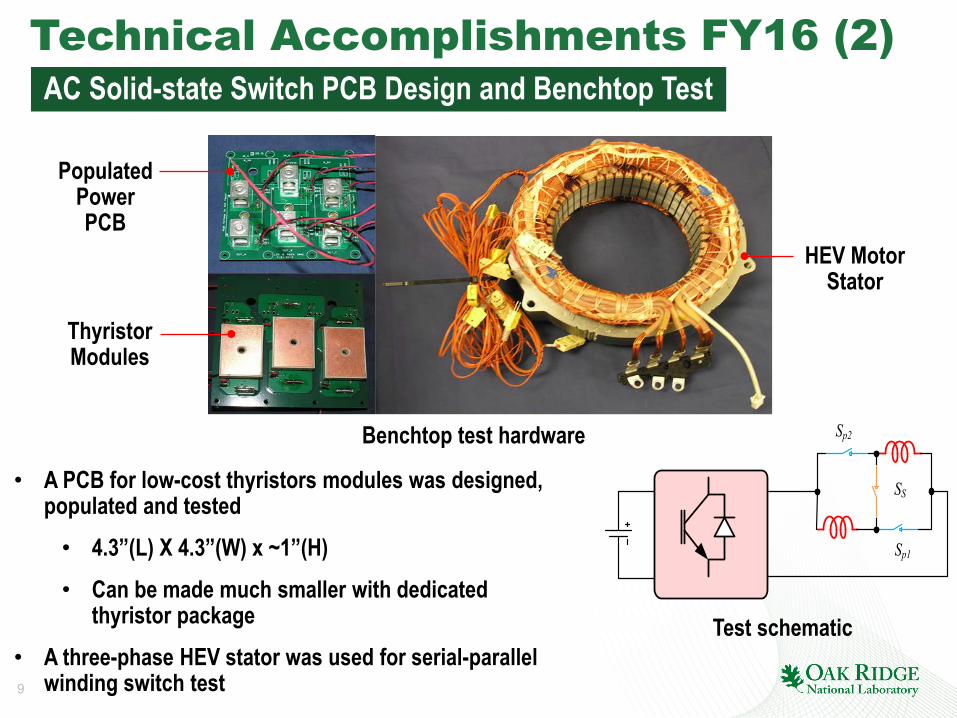
Technical Accomplishments FY16 (2)AC Solid-state Switch PCB Design and Benchtop Test
Populated PowerPCB
ThyristorModules
HEV MotorStator
• A PCB for low-cost thyristors modules was designed, populated and tested• 4.3”(L) X 4.3”(W) x ~1”(H)• Can be made much smaller with dedicated
thyristor package• A three-phase HEV stator was used for serial-parallel
winding switch test
Sp2
Sp1
SS
Benchtop test hardware
Test schematic
10
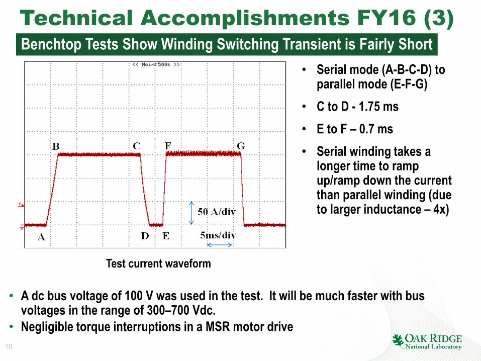
Technical Accomplishments FY16 (3)Benchtop Tests Show Winding Switching Transient is Fairly Short
Test current waveform
• A dc bus voltage of 100 V was used in the test. It will be much faster with bus voltages in the range of 300–700 Vdc.
• Negligible torque interruptions in a MSR motor drive
• Serial mode (A-B-C-D) to parallel mode (E-F-G)
• C to D - 1.75 ms • E to F – 0.7 ms• Serial winding takes a
longer time to ramp up/ramp down the current than parallel winding (due to larger inductance – 4x)
11
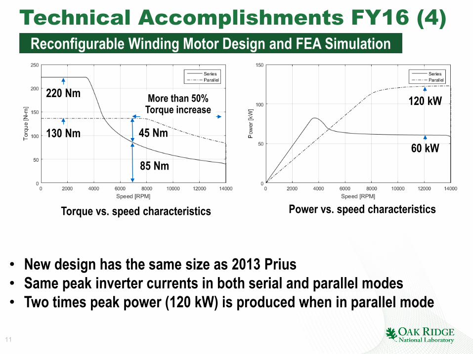
Technical Accomplishments FY16 (4)Reconfigurable Winding Motor Design and FEA Simulation
• New design has the same size as 2013 Prius • Same peak inverter currents in both serial and parallel modes• Two times peak power (120 kW) is produced when in parallel mode
Torque vs. speed characteristics Power vs. speed characteristics
(120 kW vs 60 kW),
60 kW
120 kW
130 Nm
220 Nm
85 Nm
45 Nm
More than 50%Torque increase
12
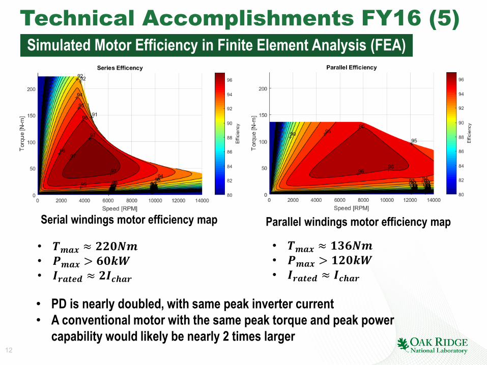
Technical Accomplishments FY16 (5)Simulated Motor Efficiency in Finite Element Analysis (FEA)
Serial windings motor efficiency map Parallel windings motor efficiency map
• 𝑻𝑻𝒎𝒎𝒎𝒎𝒎𝒎 ≈ 𝟐𝟐𝟐𝟐𝟐𝟐𝟐𝟐𝒎𝒎• 𝑷𝑷𝒎𝒎𝒎𝒎𝒎𝒎 > 𝟔𝟔𝟐𝟐𝟔𝟔𝟔𝟔• 𝑰𝑰𝒓𝒓𝒎𝒎𝒓𝒓𝒓𝒓𝒓𝒓 ≈ 𝟐𝟐𝑰𝑰𝒄𝒄𝒄𝒄𝒎𝒎𝒓𝒓
• 𝑻𝑻𝒎𝒎𝒎𝒎𝒎𝒎 ≈ 𝟏𝟏𝟏𝟏𝟔𝟔𝟐𝟐𝒎𝒎• 𝑷𝑷𝒎𝒎𝒎𝒎𝒎𝒎 > 𝟏𝟏𝟐𝟐𝟐𝟐𝟔𝟔𝟔𝟔• 𝑰𝑰𝒓𝒓𝒎𝒎𝒓𝒓𝒓𝒓𝒓𝒓 ≈ 𝑰𝑰𝒄𝒄𝒄𝒄𝒎𝒎𝒓𝒓
• PD is nearly doubled, with same peak inverter current• A conventional motor with the same peak torque and peak power
capability would likely be nearly 2 times larger

13
Differential Efficiency(Effparallel – Effserial where overlapping)
• Parallel configuration is more efficient at high speeds, particularly with low torques• Improvement can be as high as 10%• Translates into higher continuous power rating
• Combined operation increases power and efficiency at high speeds
Combined Efficiency(Optimal efficiency selected)
Technical Accomplishments FY16 (6)MSR Motor Combined and Differential Efficiency by FEA
Effserial > Effparallel
Effserial < Effparallel

14
• Same motor volume of 4.712 liter • Use only ~ 60% PM in new design - important cost reduction
Technical Accomplishments FY16 (7)Use Reconfigurable Winding to Reduce PM Volume
Base design with serial windings. Stack length of 150 mm, stator outer radius of 100 mm, and
𝑰𝑰𝒓𝒓𝒎𝒎𝒓𝒓𝒓𝒓𝒓𝒓 ≈ 𝑰𝑰𝒄𝒄𝒄𝒄𝒎𝒎𝒓𝒓
Serial/parallel reconfigurable windings design. Stack length of 75 mm, stator outer radius of 141
mm, and 𝑰𝑰𝒓𝒓𝒎𝒎𝒓𝒓𝒓𝒓𝒓𝒓 ≈ 𝟐𝟐 𝑰𝑰𝒄𝒄𝒄𝒄𝒎𝒎𝒓𝒓

15
• 43.6 % PM volume reduction was achieved
• PM mass reduced from 2.8 kg to 1.58 kg
• Slightly increased peak power (from 85 to 92 kW) with same motor volume
Technical Accomplishments FY16 (8)Torque-speed and Power-speed Characteristics of the Two Motors
Torque vs. speed (upper) and power vs. speed (lower) characteristics of the base and reconfigurable winding design in serial and parallel mode
85 kW
92 kW
16
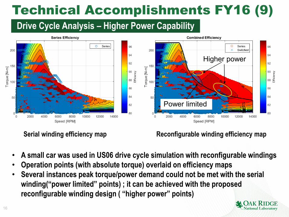
• A small car was used in US06 drive cycle simulation with reconfigurable windings• Operation points (with absolute torque) overlaid on efficiency maps• Several instances peak torque/power demand could not be met with the serial
winding(“power limited” points) ; it can be achieved with the proposed reconfigurable winding design ( “higher power” points)
Technical Accomplishments FY16 (9)Drive Cycle Analysis – Higher Power Capability
Serial winding efficiency map Reconfigurable winding efficiency map
Power limited
Higher power
17
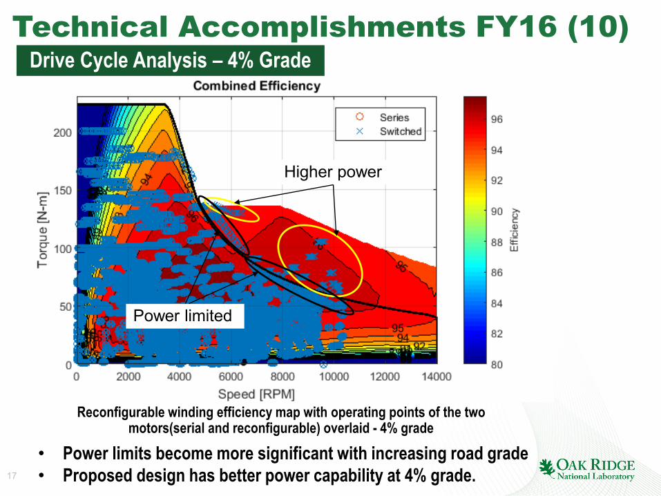
Technical Accomplishments FY16 (10)
• Power limits become more significant with increasing road grade• Proposed design has better power capability at 4% grade.
Drive Cycle Analysis – 4% Grade
Reconfigurable winding efficiency map with operating points of the two motors(serial and reconfigurable) overlaid - 4% grade
Power limited
Higher power
18
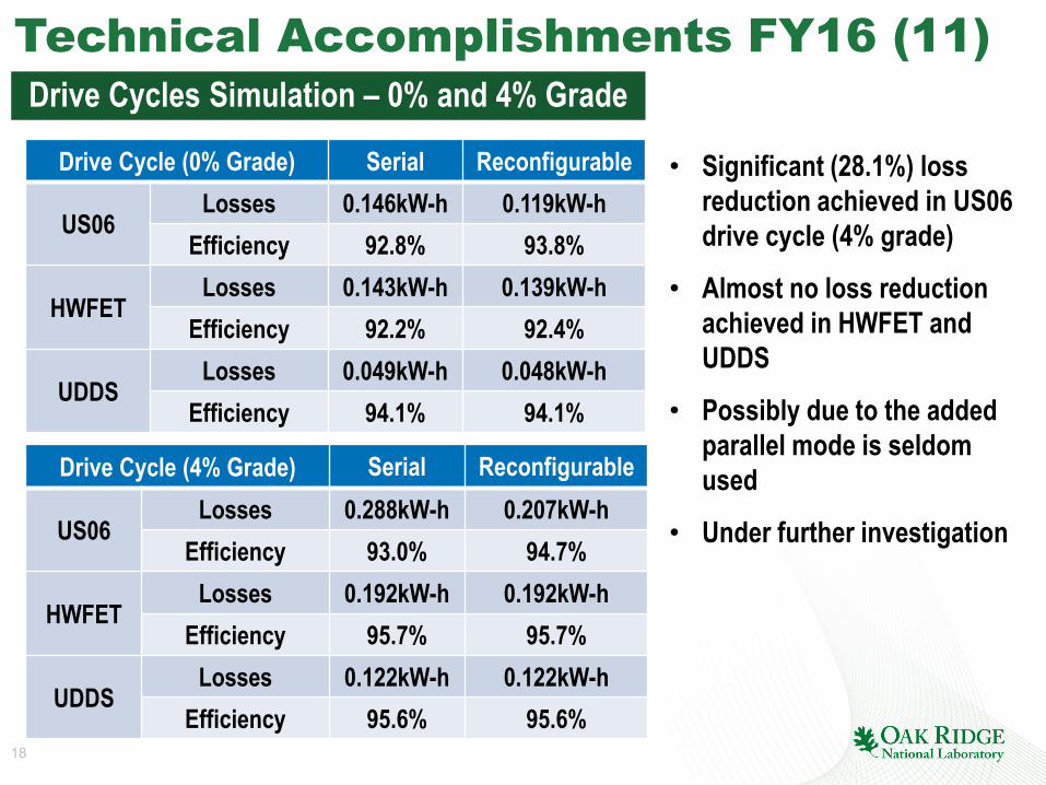
Drive Cycle (4% Grade) Serial Reconfigurable
US06Losses 0.288kW-h 0.207kW-h
Efficiency 93.0% 94.7%
HWFETLosses 0.192kW-h 0.192kW-h
Efficiency 95.7% 95.7%
UDDSLosses 0.122kW-h 0.122kW-h
Efficiency 95.6% 95.6%
Drive Cycle (0% Grade) Serial Reconfigurable
US06Losses 0.146kW-h 0.119kW-h
Efficiency 92.8% 93.8%
HWFETLosses 0.143kW-h 0.139kW-h
Efficiency 92.2% 92.4%
UDDSLosses 0.049kW-h 0.048kW-h
Efficiency 94.1% 94.1%
Technical Accomplishments FY16 (11)Drive Cycles Simulation – 0% and 4% Grade
• Significant (28.1%) loss reduction achieved in US06 drive cycle (4% grade)
• Almost no loss reduction achieved in HWFET and UDDS
• Possibly due to the added parallel mode is seldom used
• Under further investigation
19
Responses to Previous Year Reviewers’ CommentsReviewer comment: One reviewer pointed out that “the problem is practical implementation of such concepts due to requirement of additional switches, torque interruptions and potential circulating current. ” and concluded “system level understanding is critical in evaluating the benefits of such concept.”Response/Action: We totally agree with the reviewer’s comments. As a matter of fact, we have taken actions on minimize the cost/volume of the additional switches, as well as the torque interruptions, which are reported in FY16 accomplishments. We noticed the circulating current issue too and are currently working on it. We will improve our system level understanding by conducting more system level simulations.
Reviewer comment: One reviewer pointed out that there is “some lack of integration with other efforts, in terms of coordinating with absolute end users, e.g. , automotive and aerospace industry who could potentially benefit from the technology.”Response/Action: We agree with the reviewer’s comments. It is crucial to talk to potential end users, understand what they need and cooperate with them and develop something that they can use later. During FY15 AMR, some industrial people talked to us and showed great interests on our work. Meetings with USCAR have been held to present the findings to the domestic OEMS. In FY16, we have submitted two papers to conferences.
Reviewer comment: Two reviewers pointed that details about our new approach has not been shared.Response/Action: We agree with the reviewers’ comments. Some of our design is under patent review, once the review is finished. We will be able to share more information. In the meantime, we have submitted two papers to conferences.

20
Collaboration and Coordination with Other Institutions
• Borg Warner ─ System cost evaluation and design/install motor stator hairpin windings according to our optimized design.

21
Remaining Challenges and Barriers
• Cost of additional parts (e.g. switches/controls)• Complexity of motor geometries and assemblies that are
required to achieve MSR

22
Proposed Future Work
• Remainder of FY16– Simulate/optimize and build/test the benchtop prototype• Perform simulation/optimization on the benchtop prototype to
achieve DOE 2022 targets• Build/test the benchtop prototype
• FY17– Select the final approach, perform system modeling,
optimization, and build/test final prototype• Select final design• Perform system modeling/optimization on the final prototype• Build/test the final prototype

23
Summary• Relevance: This project targets PD, SP, cost and drive cycle efficiency• Approach: MSR motors can accomplish these goals through electric motor designs,
winding arrangements (e.g. reconfigurable windings), power electronics integration and control techniques
• Collaborations: Actively seeking collaborations with Borg Warner on motor hairpin winding installation and possibly new design cost evaluation
• Technical Accomplishments: – Designed/fabricated a low-cost ac solid-state ac switch PCB using thyristors– Benchtop component test showed a very short reconfiguration transient time of 5
ms, limiting torque interruption duration– FEA results confirmed doubled peak power can be achieved with a reconfigurable
winding design– A reduction of 40% on PM volume was achieved in FEA with another reconfigurable
winding motor design, reducing cost– Drive cycle simulation showed proposed design has higher power capability,
especially at graded roads• Future Work:
– Optimize design and build/test benchtop prototype (FY16)– Modeling/optimization of the final design and build/test final prototype (FY17)