electric drive system speed sensor fault-tolerant control ... · pdf fileelectric drive system...
TRANSCRIPT
Sensors & Transducers, Vol. 160, Issue 12, December 2013, pp. 99-105
99
© 2013 by IFSAhttp://www.sensorsportal.com
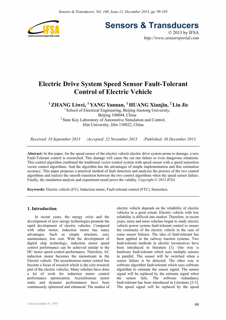
Electric Drive System Speed Sensor Fault-Tolerant Control of Electric Vehicle
1 ZHANG Liwei, 1 YANG Yannan, 1 HUANG Xianjin, 2 Liu Jie
1 School of Electrical Engineering, Beijing Jiaotong University, Beijing 100044, China
2 State Key Laboratory of Automotive Simulation and Control, Jilin University, Jilin 130022, China
Received: 18 September 2013 /Accepted: 22 November 2013 /Published: 30 December 2013
Abstract: In this paper, for the speed sensor of the electric vehicle electric drive system prone to damage, a new Fault-Tolerant control is researched. This damage will cause the car run failure or even dangerous situations. This control algorithm combined the traditional vector control system with speed sensor with a speed sensorless vector control algorithms. And the algorithm has the advantages of simple implementation and flux estimation accuracy. This paper proposes a practical method of fault detection and analyzes the process of the two control algorithms and realizes the smooth transition between the two control algorithms when the speed sensor failure. Finally, the simulation analysis and experiment result prove the validity. Copyright © 2013 IFSA. Keywords: Electric vehicle (EV), Induction motor, Fault-tolerant control (FTC), Sensorless.
1. Introduction
In recent years, the energy crisis and the development of new energy technologies promote the rapid development of electric vehicles. Compared with other motor, induction motor has many advantages. Such as simple structure, easy maintenance, low cost. With the development of digital chip technology, induction motor speed control performance can be achieved similar to the DC motor speed control performance. Therefore, AC induction motor becomes the mainstream in the Electric vehicle. The asynchronous motor control has become a focus of research which is the core research part of the electric vehicles. Many scholars have done a lot of work for induction motor control performance optimization. Asynchronous motor static and dynamic performances have been continuously optimized and enhanced. The market of
electric vehicle depends on the reliability of electric vehicles to a great extent. Electric vehicle with low reliability is difficult into market. Therefore, in recent years, more and more scholars began to study electric vehicle power system fault-tolerant control to ensure the continuity of the electric vehicle in the case of some sensor failures. The idea of fault-tolerant has been applied in the railway traction systems. Two fault-tolerant methods in electric locomotives have been introduced in literature [1]. One way is hardware fault-tolerant which uses multiple sensors in parallel. The sensor will be switched when a sensor failure is be detected. The other way is software algorithm fault-tolerant which uses software algorithm to estimate the sensor signal. The sensor signal will be replaced by the estimate signal when the sensor fails. The software redundancy fault-tolerant has been introduced in Literature [2-3]. The speed signal will be replaced by the speed
Article number P_1585
Sensors & Transducers, Vol. 160, Issue 12, December 2013, pp. 99-105
100
estimate signal when the speed sensor failure. Two different speed estimate methods have been taken in order to improve the accuracy of the estimate speed signal. The speed signal will be chosen by maximum likelihood choice from the two estimate speed signal when the speed sensor failure. Therefore, the chosen speed signal will be the most close to the actual signal. But this solution is so complex that easy to implement. And the Fault diagnosis is complex.
Some scholars designed synovial controller to solve sensor fault [4]. The synovial controller is connected to the system when the sensor fails. Literature [5] describes the speed estimation based on Kalman filtering. Literature [6] estimates speed signal through adaptive parameter estimation method and to detect the speed sensor is normal or not through posterior reliability voting algorithm. Literature [4-6] emphasize on the theoretical analysis. These methods are not easy to be engineered.
In this paper, considering the characteristics of electric vehicle engineering, we choose software redundancy in order to increase vehicle safety factor when the speed sensor failure. This paper proposes a practical, easy to implement sensor fault tolerant control algorithms based on the speed sensorless vector control. Based on this fault tolerant control, this paper also studies the speed sensorless vector control algorithm which is combined the voltage with current model to estimate the rotor flux [7]. This paper also proposes a simple and practical speed sensor fault detection method and studied the
switching process between the speed sensor vector control algorithm and the speed sensorless vector control algorithm. Those guarantee the smoothness of the switch. Finally the simulation analysis and experiment result prove the validity.
2. The Vector Control with Estimated
Speed
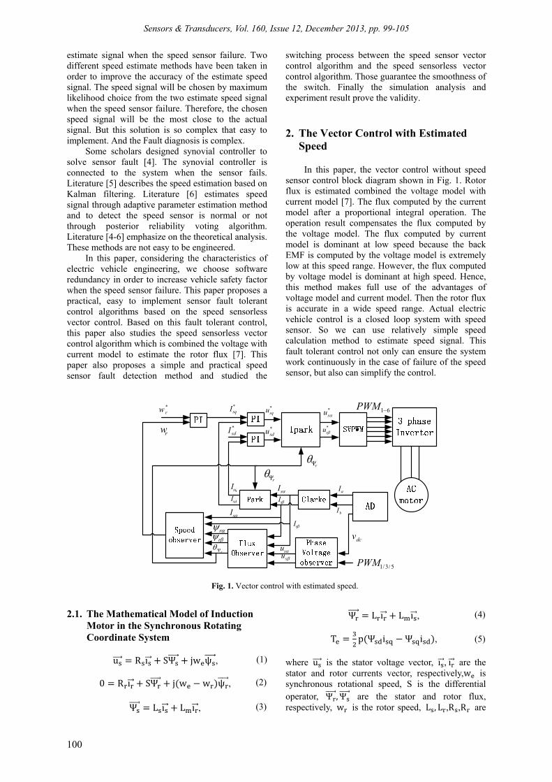
In this paper, the vector control without speed sensor control block diagram shown in Fig. 1. Rotor flux is estimated combined the voltage model with current model [7]. The flux computed by the current model after a proportional integral operation. The operation result compensates the flux computed by the voltage model. The flux computed by current model is dominant at low speed because the back EMF is computed by the voltage model is extremely low at this speed range. However, the flux computed by voltage model is dominant at high speed. Hence, this method makes full use of the advantages of voltage model and current model. Then the rotor flux is accurate in a wide speed range. Actual electric vehicle control is a closed loop system with speed sensor. So we can use relatively simple speed calculation method to estimate speed signal. This fault tolerant control not only can ensure the system work continuously in the case of failure of the speed sensor, but also can simplify the control.
rw
*rw *
sqI
*sdI
*squ
*sdu
*su
*su
r
r
r
sqI
sdIsI
sIaI
bI
dcv
5/3/1PWM
61PWM
susu
sI
sIr
r
Fig. 1. Vector control with estimated speed.
2.1. The Mathematical Model of Induction Motor in the Synchronous Rotating Coordinate System
u R ı SΨ jw ψ , (1)
0 R ı SΨ j w w ψ , (2)
Ψ L ı L ı , (3)
Ψ L ı L ı , (4)
T p Ψ i Ψ i , (5) where u is the stator voltage vector, ı , ı are the stator and rotor currents vector, respectively,w is synchronous rotational speed, S is the differential operator, Ψ ,Ψ are the stator and rotor flux, respectively, w is the rotor speed, L , L ,R ,R are

Sensors & Transducers, Vol. 160, Issue 12, December 2013, pp. 99-105
101
stator inductance, rotor inductance, stator resistance and rotor resistance respectively.
2.2. The Estimation of Speed
Equation (6) can be calculated in the literature [7] based on the induction motor equations (1)-(5). Equation (7) can be obtained by differentiating the equation (6). The rotor voltage equation (8)-(9) and rotor flux linkage equations (10)-(11) in the stationary coordinate system can be obtained from the motor mathematical models. Equation (12)-(13) can be obtained by substituting the equations (8)-(11) into equation (7). The speed of the induction motor can be obtained by synchronous speed w subtracting the slip speed w .
θ arctan , (6)
w , (7)
0 R i w ψ , (8)
0 R i w ψ , (9)
ψ L i L i , (10)
ψ L i L i , (11)
w w ψ ψ i
ψ i , (12)
w w w , (13)
3. Fault Detection and Fault Tolerate Control
Induction motor speed sensor of electric cars electric drive system is mostly optical encoder. The control system can calculate the speed signal by collecting optical encoder signal. The output signals of optical encoder have two signals A and B shown in Fig. 2. The waveform (a) is the optical encoder output signal when the optical encoder is normal. Two signals A and B are orthogonal to each other by 90 degrees. (b), (C) and (d) are the three typical fault conditions of the optical encoder. The signal of A is continuous low level in the waveform (a). The signal of A is continuous high level in the waveform (b). The signals of A and B are continuous high level in the waveform (c). Failure of the B signal is not listed. The processor DSP will calculate the wrong speed once the abnormal signal is collected. The wrong speed will cause the control command of the operator failure even cause dangerous accidents. Thus, the problem of the control command failure must be taken to resolve because of the speed sensor failure.
This paper uses a fault-tolerant control block diagram shown in Fig. 3.
Fig. 2. Four typical encoder signals.
Fig. 3 shows the block diagram of the fault-tolerant control when the speed sensor is failure which uses software algorithms for real-time speed estimation. w is the estimated speed. θΨ is the estimated rotor flux angle. w is the measured speed by the speed sensor. θΨ is the rotor flux angle calculated by the current model. The four signals are the input signals of tolerant module. The output signals will be the control signals after the fault tolerant control algorithm.
3.1. Fault Detection To detect the speed sensor fault is a very
important step for fault-tolerant control. Only the fault is detected, the control system can take measures to take the fault tolerant control algorithm. As shown in Fig. 3, signal w and signal w are parallel and signal θΨ and signal θΨ are parallel. The parallel signal can be compared in real-time. This provides a way for fault detection. Compared with the actual speed of motor, the speed signal calculated by the DSP has a great difference when the speed sensor failure. The difference can be detected quickly. For example, the digital signal processor can meet the requirements. In the experimental platform, the operating frequency of the processor is 10 KHz and the reaction time is 0.1 ms. Assuming the estimated signal is correct that is the prerequisite of fault-tolerant control. The principle can be used to determine the speed sensor fault which is acceptable in practical conditions. The measured speed is compared with the estimated speed in time. According to this principle, if |w w |
(deviation), then the speed sensor is normal. Otherwise the speed sensor is failure.

Sensors & Transducers, Vol. 160, Issue 12, December 2013, pp. 99-105
102
rw
*rw *
sqI
*sdI
*squ
*sdu
*su
*su
1
r
r
r
sqI
sdIsI
sIaI
bI
dcv
5/3/1PWM
61PWM
susu
sI
sIr
r
sqI
sdI
1rw
2rw
1rw
2
r
Fig. 3. Fault-tolerant control block diagram (Acquired signals with the subscript '1 ' and estimated signals with the subscript '2 ').
The fault tolerant control may be switched frequently in the actual working conditions. Malfunction may occur such as unintended acceleration and deceleration. The control system can collect n times speed difference to determine the speed sensor is good or bad via a simple voting options. In this way, the control system can prevent malfunctions and wrong judgments in a certain range.
3.2. Fault Tolerant Control
The control signals can be switched based on the fault tolerant control algorithm when the speed sensor failure is detected. The control system will switch the control signals from w and θ to w and θ . The switching of rotor speed signal and rotor flux angle will affect the transient performance of the motor. The switching will affect three parts such as Park transform, Park inverse transform and the speed controller of the control system. PI controller can be assumed to be a part of inertia at the instant of switching. So the PI controller has a delayed response. Park transformation needs to go through a PI controller to affect the motor in the forward path. The speed controller needs to go through two PI controllers to affect the motor. So the two parts can be assumed have no effect on the motor when the switching frequency of the digital signal processor is high. In fact, Park Transform only has an impact on the transient performance of the motor at the instant of switching. The angle difference between the two signals is θ when the control signal is switched from θ to θ . The change process of voltage vector is shown in Fig. 4. u and u can be assumed unchanged. The amplitude of the voltage vector does not change, but the phase angle of the voltage vector changes θ degree.
The change of the voltage vector will affect the synthetic stator flux vector of asynchronous motor. Thereby, the change will affect the motor torque. The stator voltage can be ignored when the motor speed is not very low. Then the relationship between the synthetic voltage vector and the synthetic stator flux vector is integral and differential relations [8]. Assuming that the motor is powered by three-phase balanced voltage, then the amplitude of stator flux value is constant. The synthetic spatial vector of stator flux rotates at a constant speed. The top trajectory of the stator flux vector is a circular. The amplitude of the voltage is proportional to the supply frequency and the direction is orthogonal to the flux vector. Then the problem between rotating magnetic field trajectory of induction motor and voltage space vector trajectory can be interchangeable.
'dd
q'q
refU
'refU
U
'dU
U
dU
'qU qU
Fig. 4. The change process of voltage vector.

Sensors & Transducers, Vol. 160, Issue 12, December 2013, pp. 99-105
103
refU
'refU
1U
2U3U
4U
5U6U
s
's
's
Fig. 5. The change process of flux vector.
Assuming induction motor is operating and the stator voltage vector is in the first sector shown in Fig. 5, the stator voltage vector changes from U to U when the phase angle changes θ degree. At the moment, the synthetic flux vector should be ψ , but the actual synthetic flux vector is ψ because voltage vector angle changes θ degree. The amplitude of the flux vector does not change, but the angle of the flux vector changes θ degree.
The motor torque expression [9] is shown in formula 14.
T π lrB F sin δ, (14)
where P is the motor poles; l is the axial length of the motor; r is the radius of the motor; B is the peak of flux density; F is the peak of magnetomotive force; δ is the torque angle.
L , r , B , F are constant at the instant of switching. The torque angle δ will change because the change of flux vector angle. Motor torque will fluctuate because the change of torque angle δ. The torque angle δ can adjust rapidly because the control response time is 0.1 ms. And the automotive power transmission bearings are large inertia part, so the system control can switch smoothly without uncomfortable.
4. Simulation AND Experimental Result
According to previously described the speed sensor failure detection method and fault-tolerant control method are modeled by Matlab / Simulink. And the algorithm is realized by S-function. Finally, the experiment result verifies the feasibility of fault-tolerant control.
4.1. Simulation Results
The asynchronous motor parameter of simulation in the simulation model is an actual asynchronous motor parameter in the electric vehicle.
The specific parameter is shown in Tab 1. Simulation algorithms are used by the discrete S-function in order to consistent with the actual program to the maximum extent.
The estimated waveform of speed sensorless vector control is shown in the Fig. 6.
Tab. 1. The parameters of induction machine.
Parameter Value Parameter Value
P /kW 7.5 U /V 51 f /Hz 115 R /Ω 0.004893 R /Ω 0.006277 L /mH 1.8503 L /mH 1.86608
The above-mentioned control strategy is modeled in order to verify the dynamic and steady-state performance of speed sensorless vector control and the speed estimation algorithm. The speed command value of motor is 1500 r/min without additional load. The estimated speed waveform is shown in Fig. 6 (a). The control algorithm combined voltage model and current model has a fast response speed and a good tracking effect. The estimated rotor flux waveform is shown in Fig. 6 (b). And the estimation precision is accurate. The estimated phase voltage is shown in Fig. 6 (c) in 10 kHz sampling frequency. The estimated rotor flux angle is shown in Fig. 6 (d). The simulation results are consistent with the theoretical analysis proved the feasibility of the algorithm.
In order to simulate actual working condition, the speed command value is 1500 r/min with a sudden 15N • m torque. And the control algorithm is switched at 1 s. The speed waveform has no fluctuation at the switching time and the switching process is smooth. The simulation waveform is shown in Fig. 7 (a). In Fig. 7 (b), the electromagnetic torque of the motor has a pulsating at the switching time because the mutation of the voltage vector angle. But the electromagnetic torque can recover smooth quickly which verifies the correctness of the algorithm. Fig. (c) shows the motor phase current waveform and the current mutation phenomenon does not appear at the switching process. The switch process is smooth.
4.2. Experimental Results
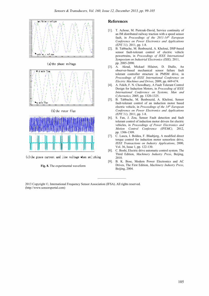
A motor bench is built to verify the above-mentioned fault-tolerant control algorithm. The experimental motor parameters are shown in Table 1. The control system is based on TMS320F28335 floating-point digital signal processor. And the motor control is speed closed-loop control. The modulation method and control method are same with the simulation. The switching frequency is 10 kHz and the DC bus voltage is 72 V. The motor speed is controlled at 1500 r/min. Fig. 8 (a)

Sensors & Transducers, Vol. 160, Issue 12, December 2013, pp. 99-105
104
and Fig. 8 (b) is the motor phase voltage and rotor flux waveform in the experiment. The experimental waveforms verify the control algorithm. The two waveforms shown in Fig. 8 (c) are motor phase current and line voltage at the switching process when the motor speed is 1500 r/min. The experimental waveforms do not have mutation and distorted and the switching process is smooth. The speed sensor failure fault-tolerant control algorithm has been verified.
Fig. 6. The estimated waveforms.
Fig.7. The estimated waveform when switching.
5. Conclusions In this paper, fault-tolerant control is adopted in
the case of the speed sensor failure. A simple and practical fault detection method is proposed. The fault-tolerant control algorithm combined the traditional vector control algorithm and sensorless vector control algorithm. The estimated speed of sensorless vector control algorithm is accurate in a large speed range because the control algorithm combined voltage model and current model. The failure of control instructions caused by the speed sensor failure have been solved though this fault-tolerant control algorithm. This control method is simple, practical and reliable. Simulation and experimental results verify the effectiveness of this fault-tolerant control.
Sensors & Transducers, Vol. 160, Issue 12, December 2013, pp. 99-105
105
Fig. 8. The experimental waveform
References [1]. T. Achour, M. Pietrzak-David, Service continuity of
an IM distributed railway traction with a speed sensor fault, in Proceedings of the 2011-14th European Conference on Power Electronics and Applications (EPE’11), 2011, pp. 1-8.
[2]. B. Tabbache, M. Benbouzid, A. Kheloui, DSP-based sensor fault-tolerant control of electric vehicle powertrains, in Proceedings of IEEE International Symposium on Industrial Electronics (ISIE), 2011, pp. 2085-2090.
[3]. A. Akrad, Mickael Hilairet, D. Diallo, An observer-based mechanical sensor failure fault tolerant controller structure in PMSM drive, in Proceedings of IEEE International Conference on Electric Machines and Drives, 2009, pp. 669-674.
[4]. A. Fekih, F. N. Chowdhury, A Fault Tolerant Control Design for Induction Motors, in Proceeding of IEEE International Conference on Systems, Man and Cybernetics, 2005, pp. 1320-1325.
[5]. B. Tabbache, M. Benbouzid, A. Kheloui, Sensor fault-tolerant control of an induction motor based electric vehicle, in Proceedings of the 14th European Conference on Power Electronics and Applications (EPE’11), 2011, pp. 1-8.
[6]. S. Fan, J. Zou, Sensor Fault detection and fault tolerant control of induction motor drivers for electric vehicles, in Proceedings of Power Electronics and Motion Control Conference (IPEMC), 2012, pp. 1306-1309.
[7]. C. Lascu, I. Boldea, F. Blaabjerg, A modified direct torque control for induction motor sensorless drive, IEEE Transactions on Industry Applications, 2000, Vol. 36, Issue 1, pp. 122-130.
[8]. C. Boshi, Electric drive automatic control system. The Third Edition, Machinery Industry Press, Beijing, 2010.
[9]. B. K. Bose, Modern Power Electronics and AC Drives, The First Edition, Machinery Industry Press, Beijing, 2004.
__________________
2013 Copyright ©, International Frequency Sensor Association (IFSA). All rights reserved. (http://www.sensorsportal.com)