elec224 goal 4
TRANSCRIPT

8/3/2019 Elec224 Goal 4
http://slidepdf.com/reader/full/elec224-goal-4 1/12
Goal 4• Integrated Circuit Technologies
ELEC 224 J. Altiti1
8/3/2019 Elec224 Goal 4
http://slidepdf.com/reader/full/elec224-goal-4 2/12
IC Technologies and Logic Levels
The 2 most used IC technologies are TTL (Transistor to Transitor Logic ) and CMOS (Complementary
Metal-Oxide Semiconductor).
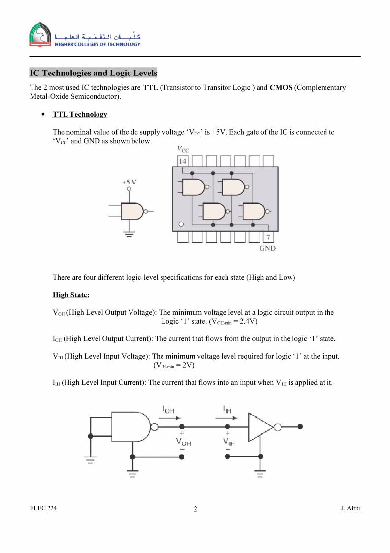
• TTL Technology
The nominal value of the dc supply voltage ‘VCC’ is +5V. Each gate of the IC is connected to
‘VCC’ and GND as shown below.
There are four different logic-level specifications for each state (High and Low)
High State:
VOH (High Level Output Voltage): The minimum voltage level at a logic circuit output in the
Logic ‘1’ state. (VOH-min = 2.4V)
IOH (High Level Output Current): The current that flows from the output in the logic ‘1’ state.
VIH (High Level Input Voltage): The minimum voltage level required for logic ‘1’ at the input.
(VIH-min = 2V)
IIH (High Level Input Current): The current that flows into an input when VIH is applied at it.
ELEC 224 J. Altiti2

8/3/2019 Elec224 Goal 4
http://slidepdf.com/reader/full/elec224-goal-4 3/12
Low State:
VOL (Low Level Output Voltage): The maximum voltage level at a logic circuit output in the
Logic ‘0’ state. (VOL-max = 0.4V)
IOL (Low Level Output Current): The current that flows from the output in the logic ‘0’ state.
VIL (Low Level Input Voltage): The maximun voltage level required for logic ‘0’ at the input.
(VIL-max = 0.8V)
IIL (Low Level Input Current): The current that flows into an input when VIL is applied at it.
Example:
ELEC 224 J. Altiti3
8/3/2019 Elec224 Goal 4
http://slidepdf.com/reader/full/elec224-goal-4 4/12
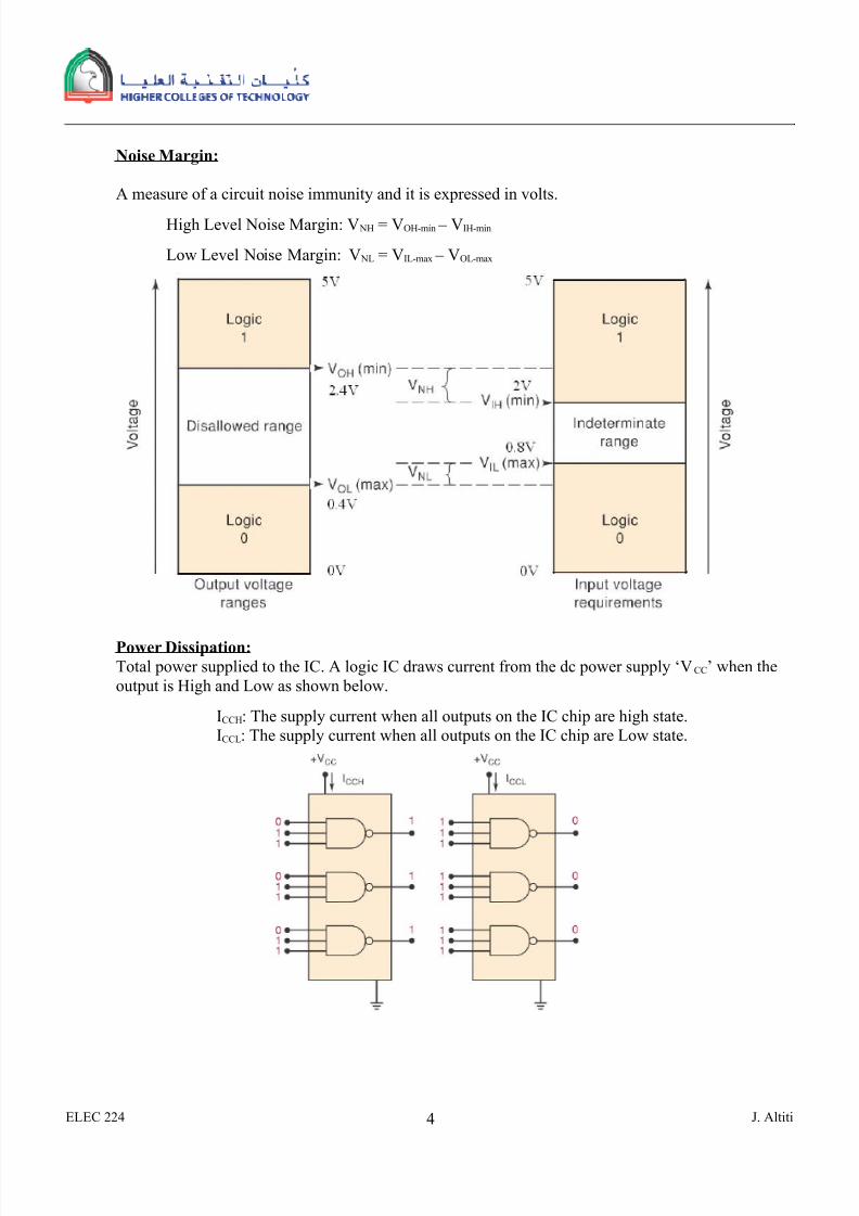
Noise Margin:
A measure of a circuit noise immunity and it is expressed in volts.
High Level Noise Margin: V NH = VOH-min – VIH-min
Low Level Noise Margin: V NL = VIL-max – VOL-max
Power Dissipation:
Total power supplied to the IC. A logic IC draws current from the dc power supply ‘VCC’ when the
output is High and Low as shown below.
ICCH: The supply current when all outputs on the IC chip are high state.
ICCL: The supply current when all outputs on the IC chip are Low state.
ELEC 224 J. Altiti4

8/3/2019 Elec224 Goal 4
http://slidepdf.com/reader/full/elec224-goal-4 5/12
CC CC D
CCLCCH
CC
V I P
I I I
⋅=
+=
2
Propogation Delay
When a signal passes (propagate) through a logic circuit, it always experience a time delay as shown
below.
The two propagation delay times for a logic gates are:
tPLH : The time between a specified reference point on the input pulse and a corresponding reference
point on the output pulse , with the output changing from the LOW level to the HIGH level.
tPHL : The time between a specified reference point on the input pulse and the corresponding
reference point on the output pulse , with the output changing from HIGH level to the LOW
level.
Note: In general , tPLH is not equal to tPHL.
The propagation time delay ‘tP’ can be defined as the average of these two times that is
ELEC 224 J. Altiti5

8/3/2019 Elec224 Goal 4
http://slidepdf.com/reader/full/elec224-goal-4 6/12
2
PHL PLH
P
t t t
+=
Speed-Power Product
It is generally desirable to have high speed (short delay time) and low power (lower supply voltage)
loigc gates. So the samller the ‘tP‘ and the lower ‘PD‘ values the better the performance of the gate.
The delay power product DP is defined as :
D p = tP PD
Fan-Out
Fan-Out: The number of load gate inputs that a given gate can drive. When the output of a logic gate
is connected to one or more inputs of other gates, a load on the driving gate is created as shown
below.
ELEC 224 J. Altiti6

8/3/2019 Elec224 Goal 4
http://slidepdf.com/reader/full/elec224-goal-4 7/12
• CMOS Technology
The of the above discussion on TTL applies to the CMOS technology. CMOS uses several nominal
value of the dc supply voltage ‘VCC’ is 5V, 3.3V, 2.5V and 1.2V.
5V COMS
3.3V COMS
ELEC 224 J. Altiti7

8/3/2019 Elec224 Goal 4
http://slidepdf.com/reader/full/elec224-goal-4 8/12
ELEC 224 J. Altiti8

8/3/2019 Elec224 Goal 4
http://slidepdf.com/reader/full/elec224-goal-4 9/12
ELEC 224 J. Altiti9

8/3/2019 Elec224 Goal 4
http://slidepdf.com/reader/full/elec224-goal-4 10/12

8/3/2019 Elec224 Goal 4
http://slidepdf.com/reader/full/elec224-goal-4 11/12
Comparison Between TTL and CMOSELEC 224 J. Altiti11

8/3/2019 Elec224 Goal 4
http://slidepdf.com/reader/full/elec224-goal-4 12/12
• HC: High Speed CMOS.
• Std: Standard• S: Schottky
• LS : Low Power Schottky
• ALS: Advanced Low Power Schottky
• AS: Advanced Schottky
ELEC 224 J. Altiti
Technology CMOS TTLStd
TTLLS
TTLS
TTL ALS
TTL AS
Device Series 74HC 74 74LS 74S 74ALS 74AS
Power dissipation@100KHz
2.5nW 0.17mW
10mW 10mW
2mW 2mW
19mW 19mW
1mW 1mW
8.5mW 8.5mW
Propagationdelay time
8ns 10ns 10ns 3ns 4ns 1.5ns
Fan-out 10 20 20 20 40
12