einbauanleitung - kaldewei-fa.secure.footprint.net whirlsystem vivo aqua eco. ... defects must be...
TRANSCRIPT

GB – Installation instructions F – Instructions d’installation I – Istruzioni di montaggio E – Instrucciones de montaje PRC – 安装说明
EINBAUANlEItUNgWhirlsystem Vivo Aqua Eco.
VIVO
AQ
UA
ECO
D
E
I
F
GB
PRC
1
Inst
alla
tion
Inst
ruct
ions
San
itary
fitt
er
CONTENTS
SCOPE OF SUPPLY ..................................................... 2
OPTIONAL EQUIPMENT ............................................... 2
TRANSPORT .............................................................. 2
BINDING INSTALLATION INSTRUCTIONS ........................ 3
SETTING UP THE WHIRLPOOL ...................................... 3
CONNECTION OF THE DRAIN AND OVERFLOW FITTINGS ................................................................... 4
FILLING THE WHIRLPOOL ............................................ 4
ALIGNMENT OF THE WHIRLPOOL ................................. 4
BATHTUB FIXING DEVICES AND SOUND INSULATION ..... 5
CONNECTION TO ELECTRICAL MAINS ........................... 5
FUNCTIONAL CHECK .................................................. 6
BRICKWORK LINING OR CASING OF THE WHIRLPOOL .... 7
TROUBLE SHOOTING .................................................. 7
INSTALLATION INSTRUCTIONS FOR SANITARY FITTER
Take a little time and read the installation instructions of this whirl system carefully. In these installation instructions, the pictograms described below are used. They refer to in-structions and notes which require your special attention.
The function of the whirl system may be disturbed.
Your health or that of the person(s) using the whirl system may be damaged.
EXPLANATION
• Kaldewei prepared these operating instructions to the best of its knowledge.
• Kaldewei reserves the right to change the contents of the operating instructions without being obliged to in-form any third parties.
• Kaldewei reserves the right to modify and improve the technical plant without being obliged to inform any third parties. Please read the attached additional information, if necessary.
• No part of these operating instructions may be repro-duced or transferred otherwise without the express ap-proval of Kaldewei.

VIVO
AQ
UA
ECO
D
E
I
F
GB
PRC
2
Inst
alla
tion
Inst
ruct
ions
San
itary
fitt
er
SCOPE OF SUPPLY
Kaldewei whirl systems are completely preassembled in the workshop and are subjected to extensive quality and functional checks.
When factory-installed components are modified, the pledge of warranty will become invalid.
Check the supply for completeness and possible transport damage immediately upon delivery of the whirlpool.
WHIRL SYSTEM VIVO AQUA ECO
• Whirlpool with drain and overflow fitting with residual wa-ter discharge and siphon (A)
• Bottom suction (B) (depending on the tub model)
• Cide suction (C) (depending on the tub model)
• Massage nozzles (D)
• Pneumatic ON/OFF switch (E)
• Air mixing controller (F)
• Level sensor (G)
• Height-adjustable feet (H)
OPTIONAL EQUIPMENT
• Drain and overflow fittings with integrated inlet
• Handles depending on bathtub model
Kaldewei shall not assume any liability for damage incurred due to improper intermediate storage and for damage in transport resulting from the non-compliance with the above instructions.
TRANSPORT
The following instructions have to be observed when trans-porting the Kaldewei whirl systems:
1. Handle the whirlpool with utmost care.
2. Transport the whirlpool in its transport box only and avoid bumping.
3. When carrying the whirlpool, hold on to the sides only - never to the instrument enclosures or hose systems.
A
D
E
CB
F
Mod
el e
xam
ple
The whirl system VIVO AQUA ECO corresponds to the Kaldewei construction series 6010.
AG HC
Mod
el e
xam
ple
F ED
Figure for CENTRO DUO and ELLIPSO DUO series
VIVO
AQ
UA
ECO
D
E
I
F
GB
PRC
3
Inst
alla
tion
Inst
ruct
ions
San
itary
fitt
er
BINDING INSTALLATION INSTRUCTIONS
The installation of the whirlpool, the electrical connection and the remedy of malfunctions and defects must be carried out by a specialized dealer who is able to prove to the authorities concerned his knowledge and competence as to the applica-tion of the national safety regulations, e.g. with regard to the power and water supply/discharge.
During the installation, protect the whirlpool sur-faces and the whirl system from damage.
Avoid soiling of any kind which might cause ob-structions when installing the waste pipe.
Pipework, hose connections and unions remain un-affected when installing the whirl system.
When factory-installed components are modified, the pledge of warranty will become invalid.
Upon completion of the work (performed by the sanitary and electrical fitters), the whirl system has to be subjected to a functional check (see page 6).
All work has to be performed using special techni-cal tools.
When installing the whirlpool, extensive sound insulation measures have to be taken (see pages below).
When whirlpools with integrated water inlet are installed a suitable backflow preventer is to be provided.
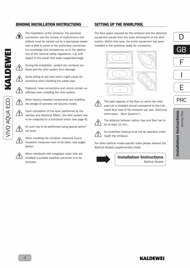
The load capacity of the floor on which the whirl-pool tub is installed should correspond to the indi-cated floor load of the whirlpool tub (see „Technical Information - Whirl Systems“).
The distance between siphon trap and floor has to be at least 10 mm.
An underfloor heating must not be operated under-neath the whirlpool.
For other bathtub model-specific notes please observe the Bathtub Models supplementary sheet.
SETTING UP THE WHIRLPOOL
The floor space required for the whirlpool and the attached equipment results from the outer dimensions of the whirl system. Within that area, the entire equipment has been installed in the workshop ready for connection.
Installation InstructionsBathtub Models

VIVO
AQ
UA
ECO
D
E
I
F
GB
PRC
4
Inst
alla
tion
Inst
ruct
ions
San
itary
fitt
er
CONNECTION OF THE DRAIN AND OVERFLOW FITTINGS
• Connect the drain and overflow fittings to the local sew-erage.
Pay attention to the proper fit of the screwed and plug-in connections.
FILLING THE WHIRLPOOL
• Close the drain and overflow fittings and fill the whirlpool with water.
The water remains in the whirlpool while the bath-tub casing is mounted.
ALIGNMENT OF THE WHIRLPOOL
The height-adjustable feet enable easy and safe alignment of the whirlpool.
The height-adjustable feet only serve as aids to set up the whirlpool in exactly horizontal position. Ad-ditional bathtub fixing devices must be mounted.
The black sound-isolating elements (A) must be set with their hard, light-coloured coated side on the outside into the blue foot caps (B).
• To align the whirlpool, turn the height-adjustable feet (C) in or out.
Align the bathtub in exactly horizontal position by means of a spirit level to ensure a reliable water drainage (drainage test).
When aligning the whirlpool, make sure that the four feet with the sound absorbers (A) are all standing firmly on the ground.
• After the alignment, secure the height-adjustable feet against displacing by means of the hexagon nut (D).
A
B
C
D
VIVO
AQ
UA
ECO
D
E
I
F
GB
PRC
5
Inst
alla
tion
Inst
ruct
ions
San
itary
fitt
er
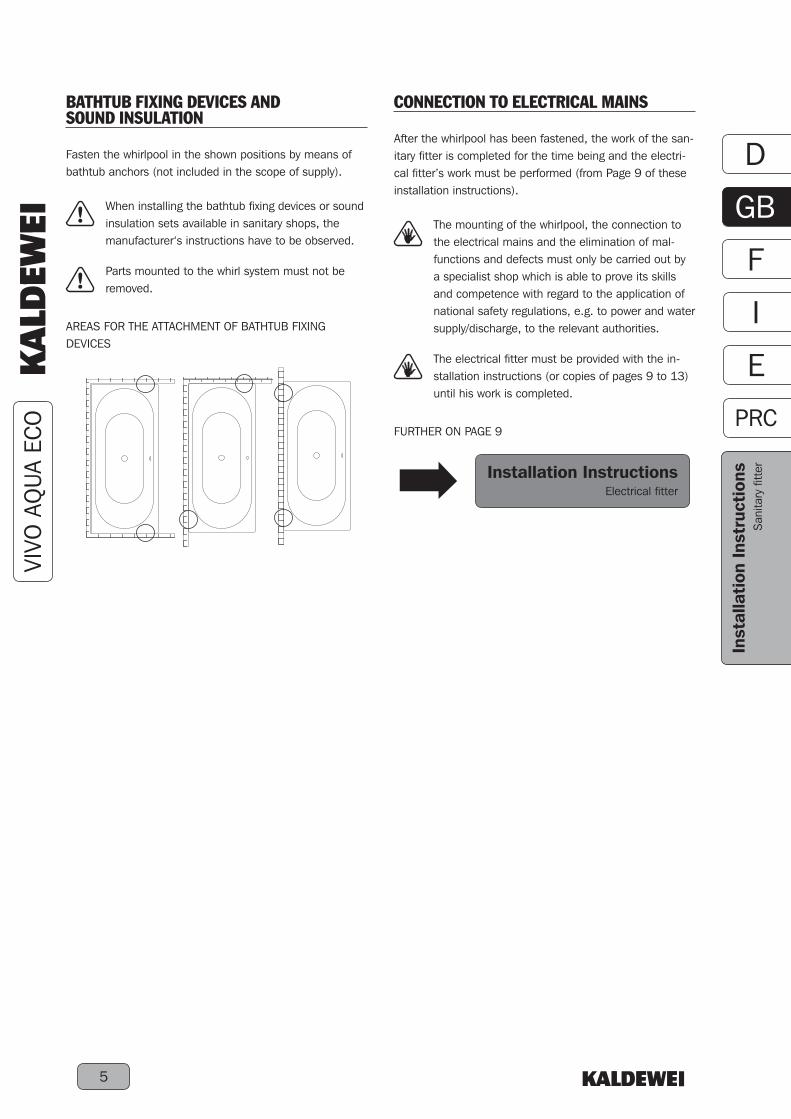
BATHTUB FIXING DEVICES AND SOUND INSULATION
Fasten the whirlpool in the shown positions by means of bathtub anchors (not included in the scope of supply).
When installing the bathtub fixing devices or sound insulation sets available in sanitary shops, the manufacturer‘s instructions have to be observed.
Parts mounted to the whirl system must not be removed.
AREAS FOR THE ATTACHMENT OF BATHTUB FIXING DEVICES
CONNECTION TO ELECTRICAL MAINS
After the whirlpool has been fastened, the work of the san-itary fitter is completed for the time being and the electri-cal fitter’s work must be performed (from Page 9 of these installation instructions).
The mounting of the whirlpool, the connection to the electrical mains and the elimination of mal-functions and defects must only be carried out by a specialist shop which is able to prove its skills and competence with regard to the application of national safety regulations, e.g. to power and water supply/discharge, to the relevant authorities.
The electrical fitter must be provided with the in-stallation instructions (or copies of pages 9 to 13) until his work is completed.
FURTHER ON PAGE 9
Installation InstructionsElectrical fitter

VIVO
AQ
UA
ECO
D
E
I
F
GB
PRC
6
Inst
alla
tion
Inst
ruct
ions
San
itary
fitt
er
FUNCTIONAL CHECK
After the whirlpool has been set up, the drain and over-flow fittings connected and the work of the electrical fitter completed, the whirl system has to be subjected to a func-tional check.
1. VISUAL INSPECTION
• Check the whirl system for visible damage.
• Check the whirlpool for horizontal installation (drainage test).
• Check the proper attachment of fixing devices and sound insulation.
• Check the whirlpool for cleanness.
The pipework, hose connections or unions and electrical equipment of the shop-mounted whirl system remain unaffected.
2. FUNCTIONAL TEST WITH THE WHIRLPOOL EMPTY
• It is not possible to switch on the whirl system (see op-erating instructions, page 6).
3. FILLING THE WHIRLPOOL
• Close the drain and overflow fittings.
• Fill the whirlpool with water up to a level of at least 5 cm above the massage nozzles (water temperature 40°C±5°C).
• Wait for 10 minutes, then carry out a leakage test.
4. FUNCTIONAL TEST
• Switch on the whirl system and let it run for about 10 minutes.
• Subject the whirl system to a leakage test.
5. DRAINING THE WHIRLPOOL
• Switch on the whirl system.
• Open the drain and overflow fittings and let the water drain off.
• Check the waste pipes (siphon) for leakages.
• When the level drops by 5 cm below the minimum water level, the whirl system must turn off automatically (see Operating Instructions, Page 6).
If the whirl system has to be readjusted or defec-tive components exchanged, the complete func-tional check has to be repeated.
VIVO
AQ
UA
ECO
D
E
I
F
GB
PRC
7
Inst
alla
tion
Inst
ruct
ions
San
itary
fitt
er
TROUBLE SHOOTING
In the case of malfunctions and defects of the whirl sys-tem, please, inform an authorized dealer or the Kaldewei after-sales service. In this case, you should have the name and serial number of your whirl system (see cover of manual) ready.
The installation of the whirlpool, the electrical connection and the remedy of malfunctions and defects must be carried out by a specialized dealer who is able to prove to the authorities concerned his knowledge and competence as to the applica-tion of the national safety regulations, e.g. with regard to the power and water supply/discharge.
The inspection chamber of the whirl system may be opened by authorized dealers or by the Kaldewei after-sales service only.
If you wish to ask any questions about your whirl system, please, do not hesitate to contact the Kaldewei after-sales service.
KALDEWEI AFTER-SALES SERVICE
Phone +49 (0) 23 82 - 785-0 Facsimile +49 (0) 23 82 - 785-200 E-Mail [email protected]
BRICKWORK LINING OR CASING OF THE WHIRLPOOL
After the functional check, the whirlpool can be brick-lined and tiled.
The brickwork lining or other casing has to be installed keeping a minimum distance of 15 mm from the system components.
For any servicing work possibly to be performed, an inspec-tion opening of 400 mm x 400 mm (height x width) has to be provided in the direct vicinity of the pump casing.
For data on size and position of the inspection openings you are referred to the Bathtub Models supplementary sheet.
Installation InstructionsBathtub Models

VIVO
AQ
UA
ECO
D
E
I
F
GB
PRC
8
Inst
alla
tion
Inst
ruct
ions
San
itary
fitt
er

VIVO
AQ
UA
ECO
D
E
I
F
GB
PRC
9
Inst
alla
tion
Inst
ruct
ions
Elec
tric
al fi
tter
CONTENTS
ELECTRICAL COMPONENTS ...................................... 10
TECHNICAL DATA ..................................................... 10
BINDING INSTALLATION INSTRUCTIONS ...................... 11
EQUIPOTENTIAL BONDING ........................................ 11
MAINS CONNECTION ................................................ 12
ELECTRICAL OPERATION TEST ................................... 12
TROUBLE SHOOTING ................................................ 12
ANNEX
TERMINAL DIAGRAM ................................................ 13
CABLE TAP BOX ....................................................... 13
PUMP TERMINAL DIAGRAM ....................................... 13
INSTALLATION INSTRUCTIONS FOR ELECTRICAL FITTER
Take a little time and read the installation instructions of this whirl system carefully. In these installation instructions, the pictograms described below are used. They refer to in-structions and notes which require your special attention.
The function of the whirl system may be disturbed.
Your health or that of the person(s) using the whirl system may be damaged.
EXPLANATION
• Kaldewei prepared these installation instructions to the best of its knowledge.
• Kaldewei reserves the right to change the contents of the installation instructions without being obliged to in-form any third parties.
• Kaldewei reserves the right to modify and improve the technical plant without being obliged to inform any third parties. Please read the attached additional information, if necessary.
• No part of these installation instructions may be repro-duced or transferred otherwise without the express ap-proval of Kaldewei.

VIVO
AQ
UA
ECO
D
E
I
F
GB
PRC
10
Inst
alla
tion
Inst
ruct
ions
Elec
tric
al fi
tter
ELECTRICAL COMPONENTS
The entire electrical equipment of the Kaldewei-whirl sys-tems has been shop-mounted ready for connection. Kaldewei-whirl systems are subjected to extensive quality and functional checks.
When factory-installed components are modified, the pledge of warranty will become invalid.
WHIRL SYSTEM VIVO AQUA ECO
• 600 W pump (A)
• Pneumatic On/Off switch (B)
• Pressure switch (C)
• Equipotential bonding strip (D)
• Cable tap box (E)
TECHNICAL DATA
Power consumption 600 WNominal consumption, pump 600 WMains connection 230 V 50/60 cps. 16 ASafety class IP65Operation Pneumatic On/Off switch
A
B
C D
Mod
el e
xam
ple
E
The whirl system VIVO AQUA ECO corresponds to the Kaldewei construction series 6010.

VIVO
AQ
UA
ECO
D
E
I
F
GB
PRC
11
Inst
alla
tion
Inst
ruct
ions
Elec
tric
al fi
tter
BINDING INSTALLATION INSTRUCTIONS
The mounting of the whirlpool, the connection to the electrical mains and the elimination of mal-functions and defects must only be carried out by a specialist shop which is able to prove its skills and competence with regard to the application of national safety regulations, e.g. to power and water supply/discharge, to the relevant authorities.
Kaldewei whirl systems are designed for domestic use and must be connected in accordance with the local regulations of public utility companies.
For the connection of the whirl system to the elec-trical mains, a separate supply line 3 x 1.5 mm² and a 4 mm² line for the equipotential bonding have to be provided by the customer.
The supply line has to be provided with an all-pole disconnecting mains switch with a contact gap of at least 3 mm to switch off the whirl system (if not being used, for servicing work).
After the whirl system has been separated from the supply line, a period of 10 minutes has to elapse (discharge of the condensers).
The wiring of the whirl system is suitable for an a.c. voltage of 230 V 50/60 cps.
The connection of the whirl system has to be pro-tected by a 16 A fuse and must be effected via a current-operated earth-leakage circuit breaker (30 mA).
During the electrical installation, protect the whirl-pool surfaces and the whirl system from damage.
Avoid soiling of any kind which might cause ob-structions when installing the waste pipe.
Pipework, hose connections and unions remain unaffected by the electrical connection of the whirl system.
When factory-installed components are modified, the pledge of warranty will become invalid.
All work has to be performed using special electric tools.
A
EQUIPOTENTIAL BONDING
The whirl system is internally cabled with a protective con-ductor.
• Connect the equipotential bonding (A) of the whirl sys-tem to the local equipotential bonding strip.
TYPE
Earthing cable - green/yellow, min. 4 mm², copper

VIVO
AQ
UA
ECO
D
E
I
F
GB
PRC
12
Inst
alla
tion
Inst
ruct
ions
Elec
tric
al fi
tter
MAINS CONNECTION
• The whirl system has to be connected to the local sup-ply network via the cable tap box.
The whirl system has to be connected to the mains under off-circuit conditions.
The supply line has to be provided with an all-pole disconnecting mains switch with a contact gap of at least 3 mm to switch off the whirl system (if not being used, for servicing work).
The connection of the whirl system has to be pro-tected by a 16 A fuse and must be effected via a current-operated earth-leakage circuit breaker (30 mA).
The standard EN 60 335-2-60 concerning whirl systems stipulates: “The equipment has to be permanently connected to a fixed line. Appliances containing electrical components have to be placed or attached such that they cannot fall into the tub.”
Components of the whirl system which carry mains voltage (230 V) when active or inactive shall be inaccessible to persons using the bath.
ELECTRICAL OPERATION TEST
Upon completion of the electrical connection work, the whirl system has to be subjected to an electrical operation test.
1. VISUAL INSPECTION
• Check the whirl system for visible damage.
• Check the 16 A fuse.
• Check the current-operated earth-leakage circuit break-er (30 mA).
• Check the all-pole disconnecting mains switch.
• Check the cable joints for proper fit.
• Check the insulation of the cable joints.
Pipework, hose connections and unions remain unaffected by the electrical connection of the whirl system.
2. FUNCTIONAL TEST
After the electrical operation test, the whirl system can be handed over to the sanitary fitter.
TROUBLE SHOOTING
In the case of malfunctions and defects of the whirl sys-tem, please, inform an authorized dealer or the Kaldewei after-sales service. In this case, you should have the name and serial number of your whirl system (see cover of manual) ready.
The installation of the whirlpool, the electrical connection and the remedy of malfunctions and defects must be carried out by a specialized dealer who is able to prove to the authorities concerned his knowledge and competence as to the applica-tion of the national safety regulations, e.g. with regard to the power and water supply/discharge.
The inspection chamber of the whirl system may be opened by authorized dealers or by the Kaldewei after-sales service only.
If you wish to ask any questions about your whirl system, please, do not hesitate to contact the Kaldewei after-sales service.
KALDEWEI AFTER-SALES SERVICE
Phone +49 (0) 23 82 - 785-0 Facsimile +49 (0) 23 82 - 785-200 E-Mail [email protected]

VIVO
AQ
UA
ECO
D
E
I
F
GB
PRC
13
Inst
alla
tion
Inst
ruct
ions
Elec
tric
al fi
tter
PUMP TERMINAL DIAGRAM
A = Power input 3 x 0.75 mm² L brown/black N blue PE yellow-green
A
TERMINAL DIAGRAM
A = Cable tap boxB = Pump nozzles (600 W, 230 V)C = Pressure switch (230 V)D = Aperture for pressure monitoring
CABLE TAP BOX
A = Power input 3 x 1.5 mm² L brown/black N blue PE yellow-greenB = Pump 3 x 0.75 mm² L brown/black N blue PE yellow-green
Power input1 x 230 V
CA
B
D
A
B

VIVO
AQ
UA
ECO
D
E
I
F
GB
PRC
14
Inst
alla
tion
Inst
ruct
ions
Elec
tric
al fi
tter

259.
806
05
/ 201
3
Franz Kaldewei GmbH & Co. KGBeckumer Strasse 33 - 3559229 AhlenGermanyTel. +49 2382 785 0Fax +49 2382 785 200www.kaldewei.com