eia-tia-222-f
TRANSCRIPT

TIdEIA ” STANDARD
ANSl/TIA/ElA-222-f-1QQ6 Approved: March 29, 1996
Structural Standards for Steel Antenna Towers and Antenna Supporting Structures
.
TIAIFJA-222-F (Revision of ELUTLbZZf-E)
JUNE 1996
TELECOMMUNICATIONS INDUSTRY ASSOCIATION
&WUSlRY ASWCUllON
. . i -- Reproduced By GLORAL
= = ENGINEERING DOCUMENTS m= WlthlhePetrniuion01EiA
ws Under Roy&y A~mement
June 10, 1996
TO: Recipients of new TIA Standards and Engineering Publications
Enclosed please find one copy of the following TINEIA Standard:
TINEIA-222-F Structural Standards for Steel Antenna Towers and Antenna Supporting Structures
Additional copies of this Standard may be obtained from the Global Engineering Documents, ’ I.S.A. and Canada (l-800-854-7179) International (303)-397-7956 at a price of $80.00 each.
Sincerely,
Cecilia tie&g Engineering Department
enclosure
Remmng me te/ecommufl/calk7flS u7au.w m 1CW,2f,“” W,,h 1*- r I^.. .-- .-,.. r̂ I---...-. -- 62: ~.

NOTICE
TIALEIA Engineering Standards and Publications are designed to serve the public interest through eliminating misunderstandings between manufacturers and purchase& facilitating interchmgeabihy and improvement of products, and assisting the purchaser in selecting and obtaining with minimum delay the proper product for his particular need. Existence of such Standards and Publications shall not in any respect preclude any member or nonmember of TIA/EIA from manufacturing or selling products not conforming to such Standards and Publications, nor &al! the existence of such Standards and Publications preclude their voluntary use by those other than TIAKIA members, whether the standard is to be used either domestically or internationally.
Standards and Publications are adopted by TIA/EIA in accordance with the American National Standards Institute (ANSI) patent policy. By such action, TIA/EIA does not assume any liability to any patent owner, nor does it assume any obligation whatever to parties adopting the Standard or Publication.
This Standard does not purport to address all safety problems associated with its use or all applicable regulatory requirements. It is the responsibility of the user of this Standard to establish appropriate safety and kahh practices and to determine the applicability of reguIatory limitations before its use.
(From Standards Proposal No. 3278, formulated under the cognizance of the TR-14.7 Structural Standards for Steel Antenna Towers and Antenna Supporting Structures Subcommittee
.
Published by
QTELECOMMUNICATIONS INDUSTRY ASSOCIATION 1996 Standards and Technology Department
2500 Wilson Boulevard Arlington, VA 22201
PRICE: Please refer to current Catalog of’E% JEDEC, and TM STANDARDS and ENGINEERING PUBLICATIONS
or tail Global Engineering Documents, USA and Canada (I-800-854-7179) International (303-397-7956)
All rights reserved Printed in U.S.A.
PLEASE!
DON’T VIOLATE THE
LAW!
This document is copyrighted by the TIA and may not be reproduced without permission.
Organizations may obtain permission to reproduce a limited number of copies through entering into a license agreement. For information, contact:
Global Engineering Documents 15 Inverness Way East
Englewood, CO 80112-5704 or call U.S.A. and Canada l-800-854-7179, International (303) 397-7956
!O
Section
STRUCTURAL STANDARDS FOR STEEL ANTENNA TOWERS AND
ANTENNA SUPPORTING STRUCTURES
CONTENTS
Page Number
OBJEC’TWE . . . . . . . . . . . . . . . . . . . . . . . . . . . . . . . . . . . . . . . . . . . . . . . . . . . . . . . . . . SCOPE...............................................................
MATERIAL ........................................................ 1.1 Standard .......................................................
LOADING .........................................................
2.1 Definitions ........................................... .......... 2.2 Nomenclature for Section 2 Loading ................................ 2.3 Standard .......................................................
2.4 References .....................................................
STRESSES .........................................................
3.1 Standard .......................................................
MANUFACTURE AND WORKMANSHIP .............................. 4.1 Standard.............................~ .........................
FACTORYFINISH ...................................................
5.1 Standard ....................................................... PLANS, ASSEMBLY TOLERANCE& AND MARKING ...................
6.1 Standard ........................................................
FOUNDATIONS AND ANCHORS ..................................... 7.1 Definitions.. ...................................................
7.2 Standard .......................................................
7.3 Special Conditions ............................................... 7.4 FoundationDrawings ............................................
SAFE‘TY FACTOR OF GUYS ......................................... 8.1 Defmition ......................................................
8.2 Standard..........................~ ............................
PRESTRESSING AND PROOF LOADING OF GUYS ..................... 9.1 Definitions.. ...................................................
9.2 Standard .......................................................
1
1
1
1
2
2
3
4
11
11
11
18
18
18
18
18
18
19
19
19
i0
21
21
21
21
21
21
22
3
a 4
5
6
7
8
* ” 9
TIAEIA-222-F
CONTENTS (Continued)
Section
c , a
Page Number
10 INITIAL GUY TENSION , . . . . . . . . . . . . . . . . . . . . . . . . . . . . . . . . . . . . . . . . . . . .
11
12
13
14
15
16
10.1 Definition ......................................................
10.2 Standard .......................................................
10.3 Method Of Measurement .......................................... OPERATIONAL REQ IJ-mMmTs .................................... 11.1 Definitions ...... ...............................................
11.2 Standard .......................................................
PROTECTIVE GROUNDING ......................................... 12.1 Definitions ..................................................... 12.2 Standard .......................................................
~JMJXPG AND WOlSKING FACILITIES .............................. 13.1 Definitions ...... ...............................................
13.2 standard .......................................................
-PWI’KE AND INSPECTION ..................................
14.1 Standard .......................................................
~A.LxIS OF EXKI’ING TOWERS AND STRUCTURES .................
15.1 Standard.............................\ ......................... COUNTY LISTINGS OF MINMLJMBASIC WIND SPEEDS ...............
ANNEXES PU-KI-WER CHECKLIST .................................. Annex A:
Annex B: DESIGN WIND LOAD ON TYFICAL MICROWAVE ANTENNAS/REFLECTORS . . . . . . . . . . . . . . . . . . . . . . . . . . . . . . . . . TABLE OF ALLOWABLE TWIST AND SWAY VALUES FOR PARABOLIC ANTENNAS, PASSIVE REFLECTORS, AND PERISCOPE SYSTEM REFLECTORS . . . . . . . . . . . . . . . . . . . . . . . . .
DETERMINATION OF ALLOWABLE BEAM TWJST Am SWAY FOR CROSS-POLARIZATION LIMITED SYSTEMS . . . . . . . . . . . . . TOWER MAINTENANCE AND INSPECTION PROCEDURES . . . . CRITERIA FOR THE ANALYSIS OF EXISTING STRUCTURES . . .
SI CONVERSION FACTORS . . . . . . . . . . . . . . . . . . . . . . . . . . . . . . . . .
COwmY ON ICE DESIGN CRITERIA FOR CO-CATION STRUCTURES.. . . . . . . . . . . . . . . . . . . . . . . . . .
Annex C:
Annex D:
Annex E:
Annex F:
Annex G:
Annex H:
Annex I:
Annex J:
22
22
22
22
22
22
22
23
23
23 23
23
23
24
24
24
24
25
59
61
71
77
83
101
103
105 GEOTECHNICAL JJqVESTIGAnONS FOR TOWERS . . . . . . . . . . . . ,109
CORROSION CONTROL OPTIONS FOR GUY ANCHORS IN DIRECT CONTACT WITH SOIL . . . . . . . . . . . . . . . . . . . . . . . . . . 111

STRUCTURAL STANDARDS FOR STEEL ANTENNA TOWERS AND ANTENNA SUPPORTING STRUCTURES
OBJECTIVE The objective of these standards is to provide I&,&= uitezia for specifying and designing steel antenna towers and antenna supporting structures. These standards are not intended to replace or supersede applicable codes. me information contained in these standards was obtained from sources as referenced and noted herein and represents, in the judgement of the subcommittee, the accepted industry practices for minimum standards fa the design of steel antenna suppohg structures. It is for general information only. while it ia believed to be accurate, this information should not be relied upon for any specific application without competent professional examination and verification of its accuracy, suitability, and applicability by a licensed professional engineer These standards utilize wind loading criteria baaed on an annual probability and are not intended to cover d environmental conditions which could exist at a particular location. These standards apply to steel antenna towers and antenna supporting structures for all classes of cmmmications service, such as AM, CATS, FM, Microwave, Cellular, TV, VHF, etc. These standards may be adapted for international use; however, it is necessary to determine the appropriate basic wind speed (fastest-mile) and ice load at the site location in the specific co~npy based on local meteorological data. Equivalent International System of Units (SI) are given iu brackets [ ] throughout these standards. SI conversion factors have been provided in Annex G. It is the responsibility of the purchaser to provide site-specific data and requirements differing from
those contained in these standards. Annex A provides a checklist for assisting the purchaser i.n specifying the requirements for a specific structure when using these standards.. The user is cautioned that local conditions of wind and ice, if known, have precedence over the minimum standards described herein.
SCOPE These standards describe the requirements for steel antenna towers and antenna supporting stnmures.
1 MAIERIAJd
1.1 Standard
1.1.1 Material shall conform to one of the following standards except as provided in 1.1.2.
1.1.1.1 Structural steel, cast steel, steel forgings, and bolts shall confom~ to the material specifications listed in the June 1, 1989, American Institute of Steel Constmction, “Specification for Structural Steel Buildings - Allowable Stress Design and Plastic Design”, hereinafter referred to as the AISC specification.
1.1.1.2 Light gauge steel stmctural members shall be structural quality as defined by the August 19, 1986, American Iron and Steel Institute, “Specification for the Design of Cold-Formed Steel Stmctural Members”, hereinafter referred to as the AISI spe@fication.
1.1.1.3 Material for tubular steel pole structures and components shall conform to section 7.0 of A.NSI/NEhtA TTl- 1983, “Tapered Tubular Steel Structures”.

- -- - -1. l ----I
1.1.2 When materials other than hose specified herein are used, the supplier must Provide certified data concerning mechanical and chemical properties.
1-1-3 Bolts and nut locking devices (excluding guy hardware).
1.1.3.1 Sl.@xitical coM&o~ md ~nnections subjected to tension where the application of externally applied load results in prying action produced by deformation of the connected parts sha.U be m& v&h b&h-strength bolts tightened to the miuimum bolt tensions specified in the November 13, 1985, AISC, “Specification for Structural Joints using ASTM A325 or A490 Bolts”.
EepbOn: where it can be shown that the stiffness of the connected parts is sufficient to rtth= prying forces to ittsignifrcauce, tension connections may be made with high-strength bolts tightened to a snug-tight condition as defined in the AISC specification refened to in 1.1.3.1.
(Note: Contact surfaces for slip-critical connections shall not be oiled or painted and for galvanized material, the contact surfaces shall be prepared in accordance with the DISC specification referred to in 1.1.3.1.)
1.1.3.2 Bearing-type connections may be made with high-strength bolts tightened to a snug-tight condition as defined in the AIsC specification referred to in 1.1.3.1.
1.1.3.3 Where high-strength bolts are used and tensioned in accordance with the mc specification referred to in 1.1.3.1, a nut-locking device is not required.
1.1.3.4 Bolts not covered in 1.1.3.3 require a nut-locking device.
1.1.3.5 Hot-dip galvan&& A490 bolts shall not be used.
1.1.4 Materials other than steel are not within the &ope of this section.
2 LOADING
2.1 Definitions
2.1.1 Dead Load - The weight of the structure, guys. and appurtenances.
2.1.2 Ice Load - The radial thickness of ice applied uniformly around the exposed surfaces of the structure, guys, and appurtenances.
2.1.2.1 solid ice.
Unless otherwise indicated, a specified radial ice thickness shall be considered as
2.1.2.2 The density of solid ice shall be considered to be 56 lb/f9 18.8 kN/m3].
2.1.2.3 The density of rime ice shall be considered to be 30 lb/@ [4.7 kN/m3].
2.1.3 Wind Load - The wind loading requ&ments specified in 2.3 (see Annex A).
2.1.3.1 Basic Wind Speed - Fastest-de wind speed at 33 ft [lo m] above ground corresponding to an annual probability of 0.02 @O-year nmrrence interval).
2.1.4 Appurtenances - Items attached to the structure such as m*MaS, transmission lines, conduits, lighting equipment, climbing devices, platforms, signs, anti-climbing devices, etc.
-
I) 2.1.4.1 Discrete Appurtenance - An appurtenance whose load can be assumed to be concentrated at a point.
2.1.4.2 Linear Appurtenance - An appurtenance whose load can be assumed to be distributed over a section of the structure.
2.2 Nomenclature for Section 2 Loading
AA Projected area of a &near appurteuance
AC Projected area of a &Crete appurtenance
42 Effective projected area of structural components in me face
AF Projected area of fit structural componeuts in one face
AC Gross area of one tower face as if the face were solid
AR Projected area of round structural components in one face
C Velocity coefficient for tubular pole structure force coefficients
CA Linear or discrete appurtenance force coeffkient
CD Guy hag force coeffkient
CF Structure force coefficient
CL GUY lift force coefficient
D Dead weight of the structure, guys, and appurtenances
Wind direction factor for flat structural components
Average diameter or average least width of a tubular pole stmctm
Wind direction factor for round structural co&ponents
Horizontal force applied to a section of the structure
Design wind load on a discrete appurtenance
Total drag force on a guy
Total lift force on a guy
0 .?F DP
DR
F
FC
FD
FL
@I
I
Kz
Lc
RR
V
WI
Gust response factor for fastest-mile basic wind speed
Weight of ice
Exposure coefficient
Chord length of guy
0 WO
d
e
Reduction factor for round structural components
Basic wind speed for the structure location
Design wind load on the structure, appurte~ccs, @Ys, etc.9 with radial ice
Design wind load on the structure, appurtenmccs, gUY% e% without ice
Diameter of guy strand
Solidity ratio

h Total height of structure
92 Velocity pressure
r Ratio of comer diameter to diameter of inscribed circle of a tubular pole structure
t Radii thickness of ice
Z Height above average ground level to midpoint of section, appurtenance or gUY
8 Clockwise angle from guy chord to wind direction vector
2.3 Standard
2.3.1 Wind and Ice Loads
2.3.1.1 The total design wind load shall include the sum of the horizontal forces applied to the structure in the direction of the wind and the design wind load on guys and discrete appurtenances.
231.2 This standard does not specifically state an ice requirement. Ice loading, depending on tower height, elevation, and exposure, may be a significant load on the stnmure in most parts of the United States. If the structure is to be located where ice accumulation is expected, consideration shall be given to an ice load when specify& the requirements for the structure. (Refer to Annexes A and H.)
2.3.2 The horizontal force (F) applied to each section of the structure shall be calculated from the equation:
F=qzGHCCFAE+~(CAAP31(lb>N ;
Not to exceed 2 QZ G &
where AC = Gross area of one tower face (ft2) [m2]
(Note: All appurtenances, including antennas, mounts and lines, shall be assumed to remain intact and attached to the stmcture regardless of their wind load capacities.)
2.3.3 The velocity pressure (Q) and the exposure coeffkient (K3;) shall be calculated from the equations (see Annex A):
Q = -00% Kz V2 (lb/ft2) for V in mi/h or
qz=.613KzV2PJforVinm/s
Kz = M3312” for 2 in ft or
Kz = Cx/1012n for 2 in meters
1.00 2 Kz < 2.58
V = Basic wid speed for the structure location (mi/h) Cm/s1
z = Height above average ground level to midpoint of the section (ft) [ml
2.3.3.1 Unless otherwise specified, the basic wind speed W) for the structure location shall be determined from section 16.
2.3.4 Gust Response Factors
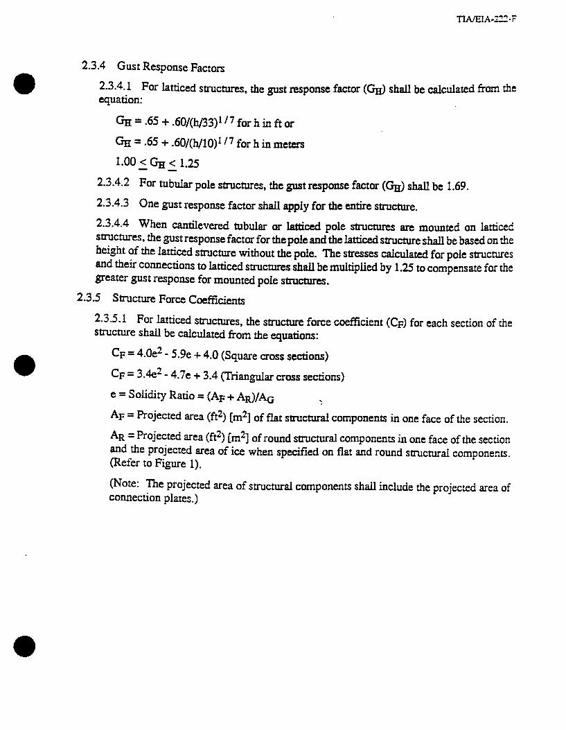
2.3.4.1 For latticed structures, the gust response factor (GH) shall be calculated from the equation:
&I = .65 + .6O/(h/33)’ I7 for h in ft or
%I = .65 + .60&h/10)’ I7 for h iu meters
1.00 2 G-JJ < 1.25
2.3.4.2 For tubular pole structures, the gust response factor (GH) shall be 1.69.
2.3.4.3 One gust response factor shall apply for the entire structure.
2.344 When cantilevered tubular or latticed pole structures are mounted on latticed structures, the gust response factor for the pole and the latticed structure shall be based on the height of the latticed structure without the pole. The stresses calculated for pole structures and their connections to latticed structures shall be multiplied by 1.25 to compensate for the greater gust response for mounted pole structures.
23.5 Structure Force Coefficients
2.3.5.1 For latticed structures, the structure force coefficient (CF) for each section of the mct~e shai.i be calculated from the equations:
CF = 4.0e2 - 5.9e + 4.0 (Square cross sections)
CF = 3.4e2 - 4.7e + 3.4 (Triangular cross sections)
e = Sdidity Ratio = (AF + AR)/& :
AF = Projected area (ft2) [rnz] of flat structural components in one face of the section.
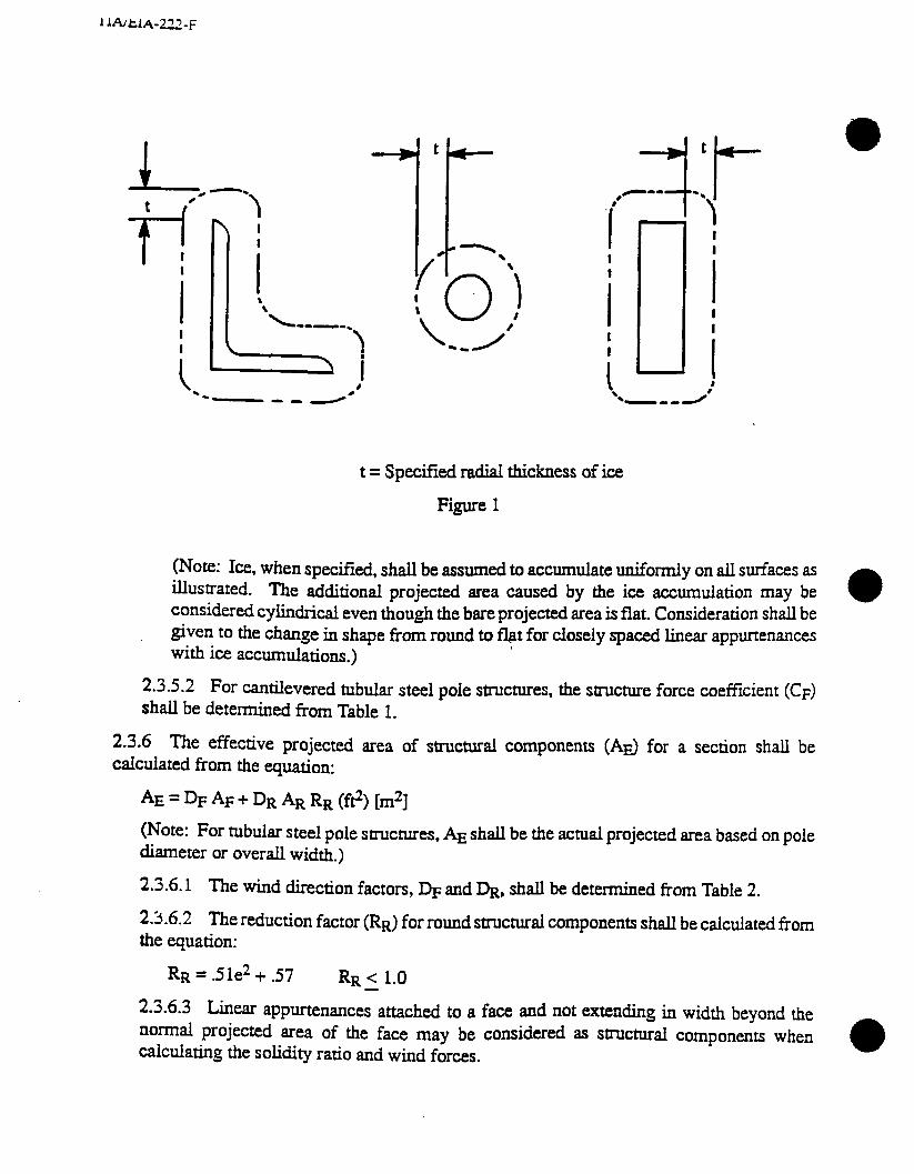
AR = Projected area (ft2) [m2] of round structural components in one face of the section and the projected area of ice when specified on flat and round structural components. (Refer to Figure 1).
(Note: The projected area of structural components shall include the projected area of connection plates.)
I 1A1tl.b222-F
t 1Ly / \ \ I \ 0’ \ -2
t = Specified radial thickness of ice
Figure 1
(Note: Ice, when specified, shall be assumed to accumulate uniformly on all surfaces as illustrated. The additional projected area caused by the ice accumulation may be considered cylindrical even though the bare projected area is flat. Consideration shall be given to the change in shape from round to flat for closely spaced linear appurtenances with ice accumulations.)
2.3.5.2 For cantilevered tubular steel pole structures, the structure force coefficient (CF) shall be determined from Table 1.
2.3.6 The effective projected area of structural components (AE) for a section shail be calculated from the equation:
AE = DF AF + DR AR RR (f$) Cm*]
(Note: For tubular steel pole structures, AE shall be the actual projected area based on pole diameter or overall width.)
2.3.6.1 The wind direction factors, & and &, shall be determined from Table 2.
2.3.6.2 The reduction factor (RR) for round structural components shall be calculated from the equation:
RR = .51e2 + .57 RR < 1.0
2.3.6.3 Linear appurtenances attached to a face and not extending in width beyond the normal projected area of the face may be considered as structural components when calculating the solidity ratio and wind forces.

TIAEIA-222-F
Table 1
Force Coefficients (CF) for Cantilevered ‘Ihbular Pole Structures
Round 16 Sided 16 Sided 12 Sided 8 Sided r < 0.26 r > 0.26
1 I
~32 1.20 1.20 1.20 1.20 1.20
32 to 64 130 013 1.78 + -cm 1.4Or 915 w 22.9 J2+(64-C) 125 . 44.8
am& 1.20
>64 59 1.08 1.4Or - .72 1.03 1.20 t
SI Units Round 16 Sided 16 Sided 12 Sided 8 Sided
r < 0.26 r > 0.26
< 4.4 1.20 1.20 1.20 1.20 1.20
4.4 to 8.7 9.74 1.78 + 1.4Or -+5
3.78 - 1.20 (Cl I3 3% . .72 +(8k7;ooc) . Q.6
> 8.7 59 1.08 - l&r .72 1.03 1.20
C = & VDp forDpinft[m]
Notes: 1. The above force coefficients apply only to cantilevered tubular pole structures which stand alone or are mounted OII the top of a latticed strwture. 2. The force coeffkients indicated account for wind load reductions under supercritica.l flow conditions and therefore do not apply to appurtenances attached to the structure. appropriate force Coeffkients for appurtenances.
Use Table 3 for
3. 4.
For ail CTOSS sectional shapes, Cf need not exceed 1.2 for any value of C. V 1s the basic wind speed for the loading condition under investigation.
Table 2
Wind Direction Factors Tower Cross
Section Square
DR 1.0 1+.75e (1.2 max) 1.0 1.0 1.0
* Measured from a line normal to the face of the structure

TWEIA-222-F
2.3.7 The force coefficient (CA) appkd to the projected area (ft2) [m21 of a hxr app~enance (AA) not considered as a ~~~ctural component shall be determined from Table 3. The force coefficient for cyli&$c~ members may be applied to the additional projected area of 0
radial i= when specified. (Refer to Figure 1.)
Table 3
Appurtenance Force CoeffkieMs
Aspect Ratio 5 7 Aspect Ratio > 25 Member Type CA CA Flat 1.4 * 2.0 cylindrical
I 0.8 1.2 Aspect Ratio = Overti length/width ratio in plane normal to wind direction. (Aspect rstio is not a function of the spacing between support points of a linear appurtenance, nor the section length ccmidered to have a uniformly distributed force.)
Note: Linear interpolation may be used for aspect ratios other than shown.
2.3-g Regardless of location, linear appurtenances not considered as structuraI components in 0 accordance with 2.3.6.3 shall be included in the term C CA AA.
2.3.9 The horizontal force (F) applied to a section of the structure may be assumed to be mi.f~nnly distributed based on the wind pressure at the mid-height of the section.
2.3.9-l For guyed masts, the section considered to have a uniformly distributed force shall not exeed the span between guy levels.
2.3.9.2 For free-standing structures, the section considered to have auniformly distributed for= shad not exceed 60 ft [ 18 m].
2.3.9.3 For tubular steel pole structures, the section considered to have a uniformly deputed force shall not exceed 30 ft [9.1 m].
2.3.10 In the absence of more accurate data, the design wind load (Fc> on a discrete appurtenance such as an ice shield, platform, etc. (excluding microwave antennas/passive reflectors) shall be calculated from the equation:
where x CA AC considers all elements of the discrete appurtenance including any feed lines, brackets, etc., related to the appurtenance. Components of a discrete appurtenance attached directly to a tower face and not projecting away from the face may be considered as structural components when c&dating the solidity ratio and wind forces.
2.3.10.1 The velocity pressure (9z> shall be c&ulated based on the centerline height of the appurtenance.

TWEIA-222-F
2.3.10.2 The gust response factor (GH) shall be calculated based on the total height of the stmtm for latticed structures (see 2.3.4.4) and shall be equal to 1.69 for tubular Pole smctures.
2.3.10.3 The design wind load (Fc) shall be applied in a horizontal direction in the direction of the wind.
2.3.10.4 The force coefficient (CA) applied to the projected area (fP) Cm21 of a discrete appurtenance (AC) shah be determjncd f&r Table 3. The farCe coefficient for Cysts members may be applied to the cylindrical portions of the appurtenance and to the additional projected area of ice when qecifred. (Refer to Figure 1).
2.3.10.5 When an equivalent flat-plate area based on Revision C of this standard (AF + 2/3 AR) is provided by a manufacturer of an appurtenance, a force coefficient of 2.0 must be applied to the equivalent flat-plate area when determiktg design wind loads. When the appurtenance is made up ofround members only, a force coeSzient of 1.8 may be applied.
2.3.11 In the absence of more accurate data, the design wind load on microwave antennas/passive reflectors shall be determined using Annex B.
2.3.12 When the azimuth orientations of antennas located at the same relative elevation on the stmctu.re are not specified, the antennas shall be assumed to radiate symmetrically about the structure.
23.13 shielding of antennas shall not be considered.
2.3.14 The design wind load on guy& shall be determined in accordance with Figure 2. The design wind load may be assumed to be uniform based on the velocity pressure (sz> at the midheight of each guy. .
2.3.15 The maximum member s&sses and structure reactions shall be detexmined considering the wind directions resulting in maximum wind forces and twisting moments. Each of the wind
. directions indicated in Table 2 shall be considered for latticed structures.
2.3.16 Each of the following load combinations shall be investigated when calculating the maximum member stresses and smcture reactions (see Annex A):
D+Wo
D+.75W1+1
(Note: When the basic wind speed is specified as ocmning simultaneously with an ice load by the purchaser or local authority, no reduction factor shall be applied to WI.)
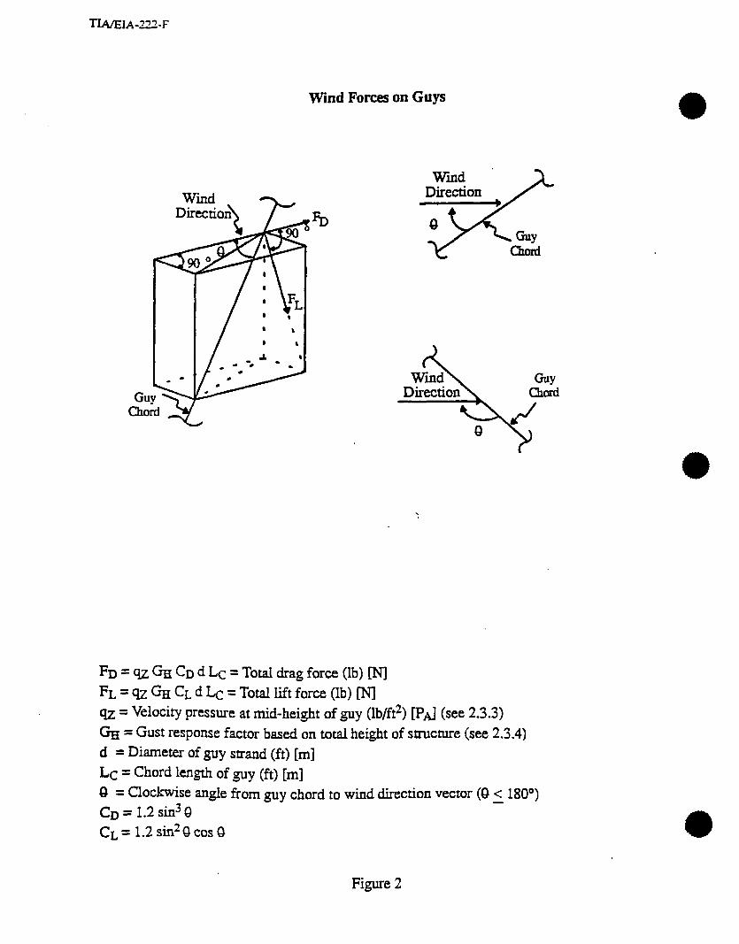
Wind Forces on Guys
FD = 9~ GH CD d Lc = Total drag force (lb) [NJ FL=qzGHCLdLc=Totalliftforce(lb) N Q = Velocity pressure at mid-height of guy (lb/ft2) PAJ (see 2.3.3) k = Gust response factor based on total height of structure (see 2.3.4) d = Diameter of guy strand (ft) [m] Lc = Chord length of guy (ft) [m] 0 = Clockwise angle from guy chord to wind direction vector (0 5 180’) CD = 1.2 sin3 8 CL = 1.2 sin28 cos 8
Figure 2
2.4 References
AAsH”lQ “Standard Specifications for Structural Supports for Highway Signs, LumGres atid Traffic Signals”, Ar~~erican Asso&~on of State Highway and %UlSpOrdOn Offici& wash.@ton, DC., 1985 with 1988 interim ~pecitication~.
ma, “‘Minirn~m Design Loads for &&iiugs and Other SUUCUIXS”, Ace 7-93, An&can Society of Civil Engineers, New York, NY, 1993. DieU W.S., “Engineering Aerodynamics”, Revised Edition, Ronald Rress Co., New York, NY, 1936.
IAs% “Recomnendatio~ for Guy& ~ast$‘, ~temati~nal Association for Shell and Spatial S~c~eS, working Group Nr 4,1981.
LOU, T., ‘Force coefficients for ‘hnanission Towers”, A Master Research Report in Civil &&=-i.ng, Department of Civil Engineering, Texas Tech University, Lubbock, TX, 1983.
sfiu, E., changery, MJ., and Fil,liben, J.J., ‘Exueme Wmd Speeds at 129 Stations in the Contiguous United States”, Building Science Series Report 118, National Bureau of Standards, Washington, D.C., 1979. 3 STRESSES
3.1 Standard
3.1-l Unless otherwise noted, structural members shall be designed iu accordance with the appropriate AISC or AISI specification.
3.1.1.1 For structures under 700 ft 1213 m] iu height, allowable stresses may be increased l/3 for both load combinations defined in 2.3.16.
3.1.1.2 For structures 1200 ft [366 m] or greater in height, allowable stresses shall not be increased.
3.1.1.3 For structures between 700 ft 1213 m] and 1200 ft [366 m] in height, allowable stresses may be increased by linear interpolation between l/3 and 0.
(Note: For structures 1200 ft [366 m] or greater in height, increases in allowable stresses do not apply due to the uncertainties of the wind effects above this height.)
3.1.1.4 Stnxture height, for purposes of determimn g allowable stresses, shall be based on the total structure height including tubular or latticed poles mounted on the structure. 3.1-l .5 Refer to 2.3.4.4 for stress increases required for cantilevered tubular pole structures mounted on latticed strucme~.
3.1.2 For guyed structures, the displacement of the mast at each guy level shall be considered wilen computing stresses.
3.1.3 The end connection and intermittent filler mqrimments of section E4 of the AI!K specification for double angle members need not be satisfied when the slenderness ratio for the buckling mode involving relative deformation between the angles is modified as follows when determining allowable stresses:
. . . . _.. - em- .
where KL
( 1 To = column slenderness of built-up member acting as a unit about the axis evolving relative deformation
a RI = largest column slenderness of individual components
( ) F, = modified column slenderness of built-up member
a = distance between connectors
4 = minimum radius of gyration of individual component
3.1.4 A reduction coefficient equal to .75 shall be used when calculating effective net areas in accordance with section B3 of the AISC specification for angle members and other similar members connected by one leg with one or two fasteners.
3.1.5 The reduction factor of 3.1.4 does not apply to the required investigation of block shear in accordance with section J4 of the AISC specification. Net shear and tension areas shall be based on hole diameters l/16 inch [1.6 mm] larger than bolt hole diameters.
3.16 Bolt holes shall not be considered pin holes, as referred to in section D3 of the AISC specification.
3.1.7 Deformation around bolt holes shall be a design consideration for the purposes of calculating allowable bearing stresses in accordance with section J3.7 of the AISC specification.
3.1-g Table J3.5 of the AISC specification shall ‘apply except at sheared edges where the minimum edge distance shall be 1.5 times the bolt diameter.
3.1.9 The measured unsupported length of a compression member shall be determined considering the rigidity of the connected parts and tbe direction of buckling about the axis under consideration.
3.1.10 Jn computing allowable stresses, when effective length factors are considered less than 1.00 for leg members or members whose ends are attached by a single bolt, justification of each factor must be shown by test or computation.
3.1.11 For a guyed structure, the stability of the structure between guy levels shall be considered when calculating allowable member stresses.
3.1.12 Limiting values of effective slenderness ratios for compression members shah preferably be 150 for legs, 200 for bracing, and 250 for redundants (members used solely to reduce slenderness of other members).
3.1.13 Bracing and redundants utilized to reduce the slenderness ratio of compression members shall be capable of supporting a force normal to the supported member equal to 1.5 percent of the supported member’s calculated axial load. This force is not to be applied simultaneously with the forces resulting from loads applied directly to the StruCttKe.
3.1.14 Structural Steel Single Angle Compression Members
3.1.14.1 Allowable compression stresses shall be calculated in mce with the ABC “Specification for Allowable Stress Design of Single Angle Members” except that the flexurahorsional buckling provisions do not apply.
3.1.14.2 Members subjected to lateral loads, which induce bending, shall meet the PrO~SiOns of section 6 of the AISC specification referred to in 3.1.14.1.
3.1.14.3 Effective length factors shall be calculate&n accordance with ANSYASCE 10-90, ‘Design of Latticed Steel Transmission Towers”, hereinafter referred to as AXE 10, (See Table 4).
(Note: The effective length factors established in ASCE 10 have been adopted to adjust the ABC allowable compression stresses for the effects of eccentric axial loading and partial end restraint.)
3.1.14.4 Effective length factors, other than those specified herein, shalI be substantiated by kStS.
3.1.14.5 Slenderness ratios (L/R) shown in Figures 3 and 4 shall be uti.Iized as a guide to cWmine measured and effective slenderness ratios.
3.1.14.6 Members shall be considered fully effective when the ratio of width to thickness (w/t) is not greater than the limiting value specified in A!XE 10.
3.1.14.6.1 When width-thickness ratios exceed the limiting value, allowable stresses shall be reduced in accordance with section 4 of the AISC specification referred to in 3.1.14.1 with Q equal to the value calculated for Fcr in AXE 10 divided by the yield stress of the member. .
3.1.14.6.2 The width w for cold-formed angles shall equal the distance from the inside bend radius to the extreme fiber but not less than the angle width minus three times the angle thickness.
3.1.14.6.3 Width-thickness ratios (w/t) shall not exceed 25.
3.1.14.7 ASCE 10 effective slenderness curves 5 and 6 of Table 4 shall be restricted to bracing and redundant members with multiple bolt or properly detailed welded connections. In addition, connections must be to membefi having adequate flexural strength to resist rotation of the joint including the effects of gussets.
3.1.14.8 Where eccentricity at a joint cannot be avoided, due consideration shall be given to the additional stresses introduced in the members.
3.1.15 For tubular pole structures, the secondary bending moments caused by vertical loads shall be considered when computing stresses.
3.1.15.1 Allowable combined bending and axial stresses for polygonal tubular steel pole structures shall be determined from Table 5.

TIAEIA-‘22-F
Table 4
ANSI/ASCE lo-90 EFFECTIVE SLENDERNESS CURVES
CURVES l-3 CURVES 4-6
4 I 120 k> 120
CURVE 1 CURVE 4
KL=L KL L R R
-=- R R
(CONCENTRIC BOTH ENDS) \ (NO END RESTRAINT)
CURVE 2 CURVE 5
KL -= 30 + .75k KL R
-= R ,28.6 -I- .762 i
(ECCENTRIC ONE W> (PARTIAL RESTRAINT ONE END)
CURVE 3 KL -= 60 + SO: R
(ECCENTRIC BOTH ENDS)
CURVE 6 KL -= R 46.2 + A15 k
(PARTIAL RESTRAINT BOTH ENDS)
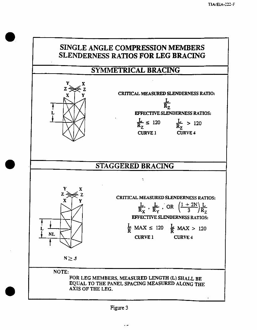
TIAXIA-Z-F
SINGLEANGLECOMPRESSION MEMBERS SLENDERNESSRATZOSFORLEGBRACING
SYMMETRICAL BRACING
CRlTICAL MEASURED SLENDERNESS RATIO:
4
EF’FEC’IWE SLENDERNESS RATIOS:
L I 120 RZ
L > 120 RZ
CURVE 1 CURVE 4
STAGGEREDBRACING .
Y x CRITICAL MEASURED SLENDERNESS RATIOS:
L R,
, & ,‘OR (’ :‘,),,
EFFECTIVE SLENDERNESS RATIOS:
i MAX I 120 k MAX > 120
CURVE 1 CURVE 4
NOTE: FOR LEG MEMBERS, MEASURED LENGTH (L) SHALL BE EQUAL TO THE PANEL SPACING MEASURED ALONG THE AXIS OF THE LEG.
Figure 3
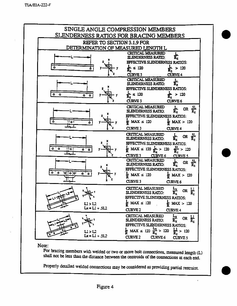
TIAEIA-222-F
SINGLE ANGLE COMPRESSION MEMBERS SLENDERNESS RATIOS FOR BRACING MEMBERS
REFER TO SECTION 3.1.9 FOR DETERMINAnON OF MEASURED LENGTH L
Lu=L1+5U CURVE2 CURVE4 *
a CRrIIcALMEAsuRED L, 1 SLENDERNESS RATIO:
7 RX ORe
%
Ll > L2
EFFEm sLEyRNEss Iwtios:
Lx=L1+5U i MAX 5 120 g > 120 u > 120
RZ cLJRvE2 CLiRVE6 CURVE5
Note: For bracing members with welded or two or more bolt cxmections, measured length (L) Shall not be less than the distme between the cemroids Of the ~nnectiolls at each end.
Properly detailed welded c.onnectiom may be considered as providing partial restraint.
Figure 4

3.1.16 The design of reinforced concrete for foundations and guy anchors shall Conform to me “Building Code Requirements for Reinforced Concrete” (AC1 318-89) issued by the American Concrete Institute.
3.1.16.1 For structures under 700 ft [213 m] in height, the required reinforced concrete strength shall equal 1.3 times the full structure reactions produced by each load combination defmed in 2.3.16.
3.1 J6.2 For structures 1200 ft 1366 m] or greater in height, the required reinforced concrete strength shall equal 1.7 times the full structure reactions produced by each load combination defined in 2.3.16.
3.1.16.3 For structures between 700 ft [213 m] and 1200 ft 1366 m] in height, the required reinforced concrete strength shall be determined by linear interpolation between 1.3 and 1.7 times the structure reactions.
3.1.16.4 Structure height, for purposes of de tennhing required reinforced concrete sue@& shall be based on the total structure height including tubular or latticed poles mounted on the structure.
Table 5 Allowable Combined Bending and Axial Stresses for Polygonal ‘lobular Steel Pole
Structurt!s
Compact Sections
F~=.60Fy
Noncompact Sections 16 Sided 215 c &w/t c 365 ‘Fyin ksi
565 < & w/t : 958 FyinMPa FB -852 Fy (CO - 0.00137 ,& w/t) ksi FB = .852 Fy (1 .O - 0.000522 ,&w/t) MPa
12 Sided 240 < &w/t < 365 Fyin ksi 630 < &w/t 2 958 FyinMPa FB -870 Fy (TO - 0.00129& w/t) ksi FB = .870 Fy (1.0 - 0.000491 ,/&w/t) MPa
8 Sided 260 c &w/t < 365 Fyinksi 683 7 &w/t 2 958 FyinMPa FB =.852 Fy (TO - 0.00114,/& w/t) ksi FB = .852 Fy (1.0 - 0.000434 & w/t) MPa
FB = Allowable combined bending and axial stress Fy= Yield strength t = Wall thickness w = Actual flat side dimension, but not less than dimension calculated using a bend radius
equal to 4t
Note: Equations obtained from EPRI report TLMRC-87-R3, “Local Buckling Strength of Polyg- onal Tubular Poles”, April 1987.

IIA/klA-122-F
4 MANUFACTURE AND WORKMANSHIP
4.1 Standard
4.1.1 Manufacturing and worha&ip shall be in accordance with CO-@ accept& standards of the structural steel fabricating industry.
4.1.2 Welding procedures shall be in accordance with the requirements of the aPProPfiate AISC or AISI specifications.
5 FACTORY FINISH
5.1 Standard
51.1 In the absence of other specific requirements, all materials shall be galvanized (see Annex A).
5.1.1.1 SUUCtUra.lMate~~ - S~I-UC~~ ~taials shall be galvanized in accordance with ASTM A123 (hot-dip). Exceptions may be made when galvanizing in accordance with ASTM A123 would be potentially detrimental to the structure or its components. Examples include applications utilizing certain high-sue@ and/or proprietary steels and weldments. In these cases, an alternative method of corrosion control shall be specsed.
5.1.1.2 Hardware - Hardware shall be galvanized in accordance with ASTM Al53 (hot-dip) or ASTM B695 Class 50 (mechanical).
5.1.1.3 Guy Strand - Zinc-coated guy strand shall be galvanized in accordance with ASTM A475 or ASTM A5S6.
a 6 PLANS, ASSEMBLY TOLERANCES, AND MARKING
6.1 Standard .
6.1-l Complete p1a.r~ assembly drawings, or other documentation shall be supplied showing the necessary marking and details for the proper assembly and installation of the material, including the design yield strength of the spuctural members and the grade of structural bolts required.
6.1.2 Tolerances for the proper layout and installation of the material; and the foundations and anchors shall be shown on the plans.
6.1.2.1 Plumb - The horizontal distance between the vertical centerlines at any two elevations shall not exceed 25 percent of the vertical distance between the two elevations.
6.1.2.2 Twist - The twist (angular’ rotation in the horizontal plane) between any two elevations shall not exceed 0.5O in 10 feet [3 m] and the total twist in the structure shall not exceed 5’.
6.1.2.3 Length - For tubular steel pole structures with telescoping joint, butt welded or flanged shaft connections, the overall length of the assembled structure shall be within plus 1 percent or minus l/2 percent of the specified height.
(Note: Horn reflectors and other types of offset-feed antennas have polarization performance requirements, which are sensitive to ar+@ar displacement from boresight e direction. Special consideration must be given to the mount, attachment hardware, installation practice, as well as the support structure, to minimize all contributing factors to initial skew or offset.)

6.1.3 All structural members or welded structural assemblies, except for hardware, shall have a part number. The part numbers shall correspond with the assembly drawings. The Part number is to be permanently attached (stamped, welded lettering, stamped on a plate that is welded to the member, etc.> to the member before all protective coatings (galvanizing, paint, etc.1 are aPPhed. The part number shall have a minimum character height of l/2 in. [13 mm], be legible and clearly visible to an inspector after erection.
7 FOUN-DAnONS AND ANCHORS
7.1 Definitions
7.1.1 Standard Foundations and Anchors - Structures designed to support the specified loads defined in Section 2 for normal sod conditions as defined in 7.1.3. Pile construction, roof msmations, foundations or anchors designed for submerged soil conditions, etc., are not to be considered as standard.
7.1.2 NonS tandard Foundations and Anchors - Structures designed to support the specified loads defined in Section 2 in accordance with site specific conditions.
7.1.3 Normal Soil - A cohesive soil with an allowable net vertical bearing capacity of 4000 pounds per square foot Cl92 kPa] and an allowable net horizontal pressure of 400 pounds Per square foot per lineal foot of depth [63 kPa per lineal meter of depth] to a maximum of 4~00 pounds per square foot 1192 pa].
(Note: Rock noncohesive soils, saturated or submerged soils are not to be considered normal
a soil.)
7.2 Standard
7.21 Stanchi foundations and anchors may be used for bidding purposes and for construction when actual soil pa&meters equal or exceed normal soil parameters.
7.22 When standard foundations and anchors are utilized for final designs, it shaU be the responsibility of the purchaser to verify by geotechnicai investigation that actual site soil parameters equal or exceed normal soil parameters. (See Annex A.)
7.2.3 Foundations and anchors shah be designed for the maximum structure reactions resulting from the specified loads defined in Section 2 using the following criteria:
7.2.3.1 When standard foundations and anchors are to be used for constnrction, “normal soil” parameters from 7.1.3 shall be used for design.
7.2.3.2 When nonstandard foundations and anchors are to be used for construction, the soil parameters recommended by the geotechnicai engineer should incorporate a minimum factor of safety of 2.0 against &imate soil strength (see Annexes A and I).
7.2.4 Uplift
7.2.4.1 Standardf oun d ti a ons, anchors, or drilled and belled piers shall be assumed to resist uplift forces by their own weight plus the weight of earth enclosed within an inverted pyramid or cone whose sides form an angle of 30’ with the vertical. The base of the cone shall be the base of the foundation if an undercut or toe is present or the top of the foundation base in the absence of the foundation undercut. Earth shall be considered to weigh 100 pounds per cubic foot [16 kN/n$] and concrete 150 pounds per cubic foot [24 kN/m3].

I rA~!zlA-222-F
7.2.4.2 Straight shaft drilled pien for st&ad foundations shall have an ultimate skin friction of 200 pounds per square f00t pa lineal foot of depth [31 kPa per Iineal meter of d@l to a maximum of 1000 pounds per square foot of shaft surface area 148 kpal for upllfr or download resistance.
7.2.4.3 Nonstandard foundations, anchors, ami &i.lkd piers shall be designed in awodance with the recommendations of a geotechnid report (see Annex I).
7.2.4.4 Foundations, anchors, and drilled piers shah be proportioned in accordance with the following:
(WR /2-o) + (WC D-25) 2 Up and (wR+wc)/l.5 1 up
where: WR = soil resistance from 7.2.4.1.7.2.4.2 or 7.2.4.3
WC = weight of concrete
Up = maximum uplift reaction
7.2.4.5 A mat or slab foundation for a seif-supporting structure shall have a minimum safety factor against overturning of 1.5.
7.2.5 The depth of standard drilled foundations subjected to lateral or overturning loads shall be proportioned in accordance with the following:
LD 2 2.0 + S/(3d) + 2 [S2/(18d2)+ S/2 + M/(3d)]ln (ft)
LD > .61 + S/(143d) + 2 [S2/(41333d2) + S/96 + M/(143d)11R [ml
where: . LD = Depth of drilled foundation below grounilevel (ft) [ml
d = Diameter of dri.Ued foundation (ft) [ml
S = Shear reaction at ground level (kips) &NJ
M = Ovemuning moment at ground level (ft-hips) [m-w
Reference: Broms, B., “Design of Laterally Loaded Piles”, Journal of the Soil Mechanics and Foundation Division Proceedings of the American Society of Civil Engineers, May, 1965.
7.3 Special Conditions
7.3.1 When a support is to be designed by other than the manufacturer, the manufacturer will be responsible for furnishing the reactions, weights, and interface details for the purchaser’s engineer to provide the necessary attachment.
7.3.2 The effects of the presence of water shall be accounted for in the design of nonstandard foundations. Reduction in the weight of materials due to buoyancy and the effect on soil properties under submerged conditions shall be considered.
7.4 Foundation Drawings
7.4.1 Foundation drawings shd indicate structure reactions, material strengths, dimensions, reinforcing steel, and embedded anchorage material type, size, and location. Foundations desiped for nomA soil conditions shall be so noted.
(Note: Normal soil design parameters and methods are presented to obtain uniform standard foundation and anchor designs for bid&g purposes. Design methods for other COnd~OnS and 0t.k foundation types must be consistent with accepted engineering practices.)
8 SAFETY FACTOR OF GUYS
8.1 Definition
8.1.1 Guy Connection - The guy connection is defmed as the hardware or mechanism by which a length of guy strand is connected to the tower, insulator, or guy anchor. The connection may include, but is not limited to, the following: shackles, in-line insulators, thimbles, turnbuckles, twin base clips, u-bolt cable dips, poured socket fittings, and grip- type dead-end connections. ‘l%vin base and u-bolt chps used on guy strand through 7/8-in. diameter shall be considered to have a maximum efficiency factor of 90 percent. In all other cases, clips on strand shall be considered to have a maximum efficiency factor of 80 percent. For all other types of end connections, manufacturer’s recommendations should be followed when determining the connection efficiency factor,
8.1.2 Safety Factor of Guys - The safety factor of guys shall be calculated by dividing the published breaking strength of the guy or guy connection strength, whichever is lower, by the maximum calculated tension design load.
8.2 Standard
8.21 For structures under 700 ft [213 m] in height, the safety factor of guys and their connections shall not be less than 2.0.
8.2.2 For structures 1200 ft [366 m] or greater in height, the safety factor of guys and their connections shall not be less than 2.5.
8.2.3 For structures between 700 ft [213 m] and 1200 II [366 m] in height, the minimum safety factor of guys and their connections shall be determined by linear interpolation between 2.0 and 2.5.
(Note: A l/3 increase in stress for wind-loading conditions does not apply to the published breaking strength of guys and their connections.)
8.2.4 Structure height, for purposes of determinin g the required safety factor of all guys and their connections, shall be based on total structure height including tubular or latticed poles mounted on the structure.
9 PRESTRESSING AND PROOF LOADING OF GUYS
9.1 Definitions
9.1.1 Prestressing of Guys - The removal of inherent constructional looseness of the guy under a sustained load.
9.1.2 Proof Loading - The assurance of mechanical strength of factory assembled end connections.
- -.. _ _-- a
9.2 Standard
9.2.1 &stressing and proof loading are not normaLly required. When specified. Presnessing and proof loading shall be performed in accordance with the recornmendati~~ of the gUY manufacturer.
(Note: For tall, guyed structures, consideration should be given to prestressing and Proof loading.)
10 INITIAL GUY TENSION 10.1 Definition
10.1-l Initial Guy Tension - The specifieci guy tension in pounds [newtons] under no wind load conditions, at the guy anchor at the specified temperature (see 10.2).
10.2 Standard
10.2.1 Initial tension in the guys, for design purposes, is normally 10 percent of the published breaking strength of the strand with upper and lower limits of 15 and 8 percent respectively. Values of initial tension beyond these limits may be used provided consideration has been given to the sensitivity of the structure to variations in initial tension and, if necessary, to dynamic behavior (see note below). Consideration shall be given to the site ambient temperature range. In the absence of site specific data, the initial tensions shall be based upon an ambient temperature of 6O*F.
(Note: The stated 8-15 percent initial tension extreme values are provided as recommended guidelines only. Specific site and terrain conditions may necessitate initial tension values outside this range. When using initial tension values above 15 percent, consideration should be given to the possible effects of aeolian vibration. mewise, when using initial tension values less tha.u g percent, consideration should be given to the effects of galloping and slack-taut pounding.)
10.3 Method of Measurement
10.3.1 Initial tension may be measured by vibration frequency, mechanical tensiometers, ~eas~~ent of guy sag, or by other suitable methods (see Annex E).
11 OPERATIONAL REQUIRE,MENTS
11.1 Definitions
11.1.1 Twist - The angular rotation of the antenna beam path in a horizontal plane from the no-wind load position at a specified elevation.
11.1.2 Sway - The angular rotation of the antenna beam path in a vertical plane from the no-wind load position at a specified elevation.
11.1.3 Displacement - The horizontal translation of a point relative to the no-wind load position of the same point at a specified elevation.
11.2 Standard (See Annex A)
11.2.1 Theminim Urn standard shall be based on a condition of no ice and a wind load based on a 50 mph basic wind speed [22.4 m/s] calculated in accordance with 2.3. The operational requirements shall be based on an overah allowable 10 dI3 degradation in radio frequency signal level.
11.2.2 Unless otherwise specified, the operational requirements for micrOWaVe antex& reflector systems shall be determined using Annexes C and D.
12 FWXECITVE GROUNDING
12.1 Definitions
12.1.1 Grounding - The means of establishing an electrical connection between the structure and the earth, adequate for lightning, high voltage, or static discharges.
12.1.2 primary Ground - A wnchcting connection between the structure and earth or some conducting body, which serves in place of the earth.
12.1.3 Secondary Ground - A conducting connection between an appurtenance and the structure.
(Note: Ground wire should not be encased in the foundation.)
12.2 Standard (See Annex A)
12.2.1 Structures shall be directly grounded to a primary ground.
12.2.2 A minimum ground shail consist of two 98 in. [16 mm] diameter galvanized stee! ground rods driven not less than 8 ft [25 m] into the ground, 180* apart, adjacent to the stmcmre base. The ground rods shah be bonded with a lead of not smaller than No. 6 [5 mm] tinned bare copper connected to the nearest leg or to the metal base of the structure. A similar ground rod shall be installed at each guy anchor and similarly connected to each guy at the anchor.
12.2.3 Self-supporting towers excee&ng 5 ft [1.5 m] in base width shall have one ground rod per leg installed as above.
12.2.4 All equipment on a structure shah be connected by a secondary ground.
12.2.5 Remote passive reflectok are exempt from the grounding requirements specified herein.
13 CLMMNG AND WORKING FACZIUTJES
13.1 Definitions
13.1.1 Climbing Facilities - Components specifically designed or provided to permit access, such as fixed kkhs, step bolts, or snuctu.ral members.
13.1.2 Climbing Safety Devices - Equipment devices other than cages, designed to minimize accidental falls, or to Iitnit the distance of such falls. The devices permit the person to ascend or descend the structure without having to continually manipulate the device or any part of the device. The climbing safety device usually consists of acarrier, safety sleeves, and safety beits.
13.1.3 Working Facilities - Work platforms and access runways.
13.1.4 Hand or Guardrds - Horizontal barriers erected along the sides or ends of working facilities to prevent falls.
13.2 Standard
13.2.1 Climbing and working facilities, hand or guardrails, and climbing safety devices shall be provided when specified by the purchaser. (See Annex A.)
13.2.2 Climbing facilities shah be designed to support a minimum 250 [l.l kN] pound concentrated live load.
TIAEIA-222-F
13.2.2.1 When fmed ladders are specified as the climbing facility, they shall meet the fo~o~g minimum requirements:
a. Side rail spa&g - 12 in. [300 mm] minimum clear width.
b. Rung spacing - 12 in. [30O mm] minimum center-to-center, 16 in. [410 mm] maximum.
C. Rung diameter - 5/8 in. [16 mm] minimum.
13.2.2.2 When step bolts are specified, they shall meet the following requirements:
a. Clear Width - 4 l/2 in. [llO mm] minimum.
b. Spacing - 12 in. minimum [300 mm] center to center, alternately spaced, 18 in. 1460 mm1 maximum.
c. Diameter - 5/S in. 116 mm] minimum.
13.23 Climbing safety devices shall meet the design requirements of the American National Standards Institute (ANSI) A14.3-1984, “Safety Requirements for Fixed Ladders”, Se&on 7.
13.24 Support structures for working facilities shall be designed to support a uniform live load of 25 lb/ft’ Il.2 kpa], but in no case shall the support structure be designed for less than a total he load of 500 pounds 12.2 ItN]. Working surfaces, such as grating, shall be designed to support two 250-pound [ 1.1 IrN] loads. These loads are not to be applied concurrently with wind and ice loads.
132.5 Hand or guardrails shall be designed to support a minimum concentrated live load of 150 pounds LO.67 kN1, applied in any direction. .
(Note: 13.2 is intended to provide m,i,nim m requirements for new structures. It is not intended to replace or supersede applicable laws or codes.)
14 -ANCE AND INSPECTION
14.1 Standard
14.1.1 Maintenance and inspection of steel antenna towers and antenna supporting structures should be performed by the owner on a routine basis.
(Note 1: It is recommended that all structures be inspected after severe wind and/or ice storms or other extreme loading conditions.) ,
(Note 2: Recommended inspection and maintenance procedures for towers are provided in Annex E.)
(Note 3: Shorter inspection intervals should be considered for structures in coastal salt water environments, in corrosive atmospheres, and in areas subject to frequent vandalism.)
15 ANALYSIS OF EXNING TOWERS AND STRUTS
15.1 Standard
15.1-l Steel antenna towers and other suppo~g stNctures should be analyzed when changes occur to the original design or operational loading conditions. Recommended criteria for the analysis of existing structures are provided in Annex F.
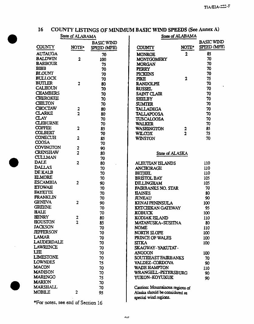
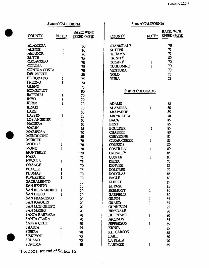
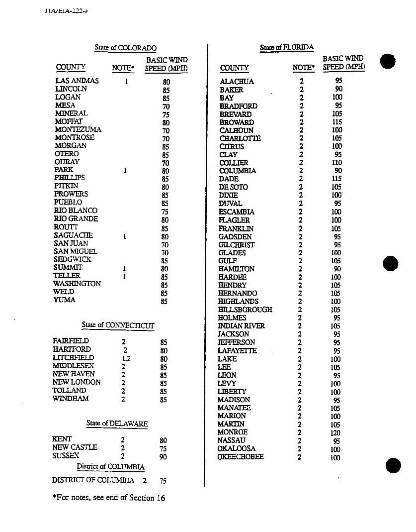
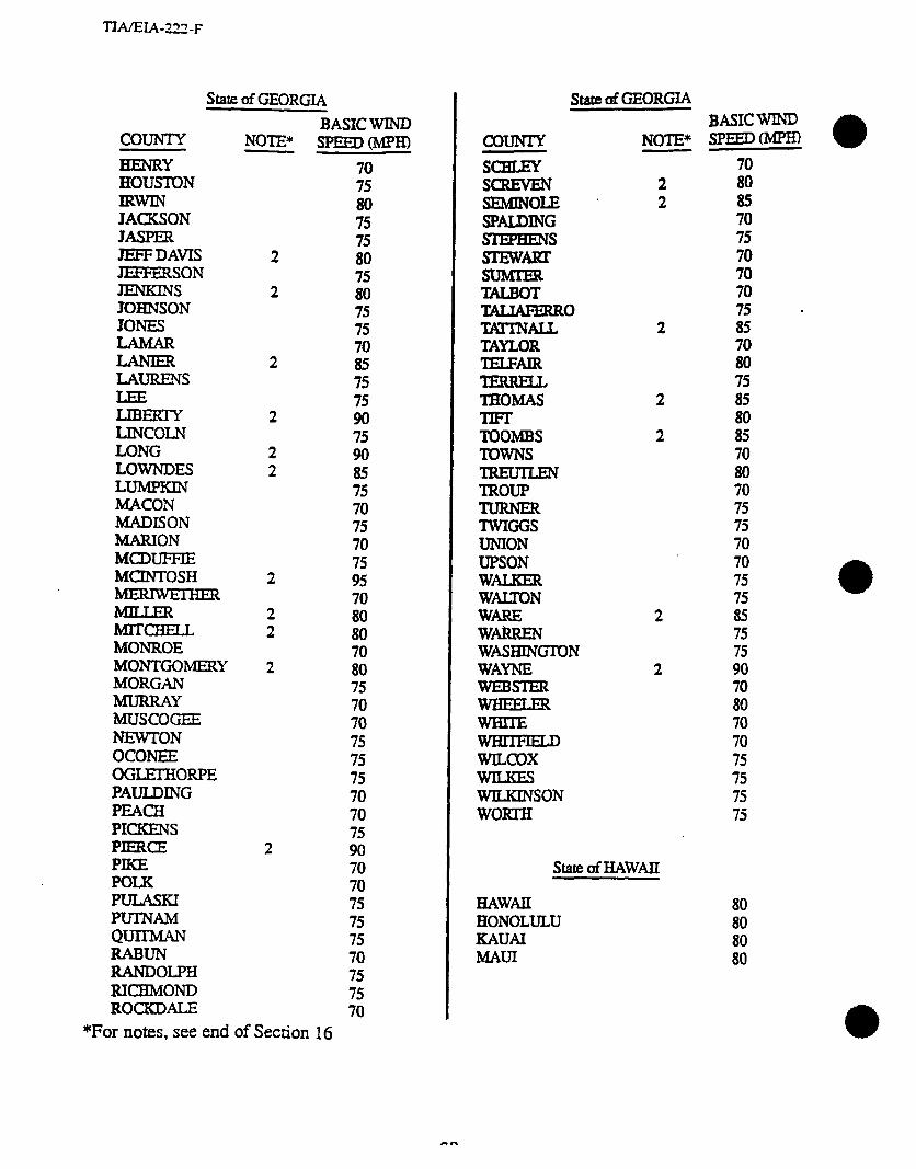
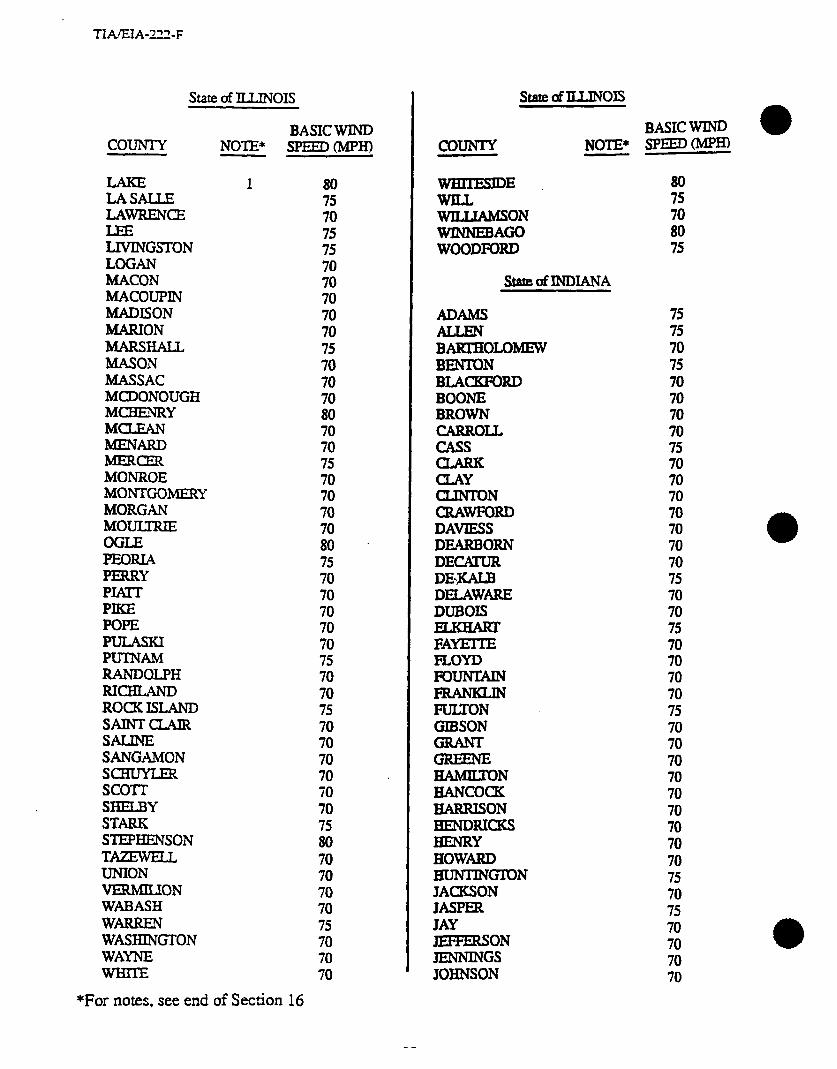
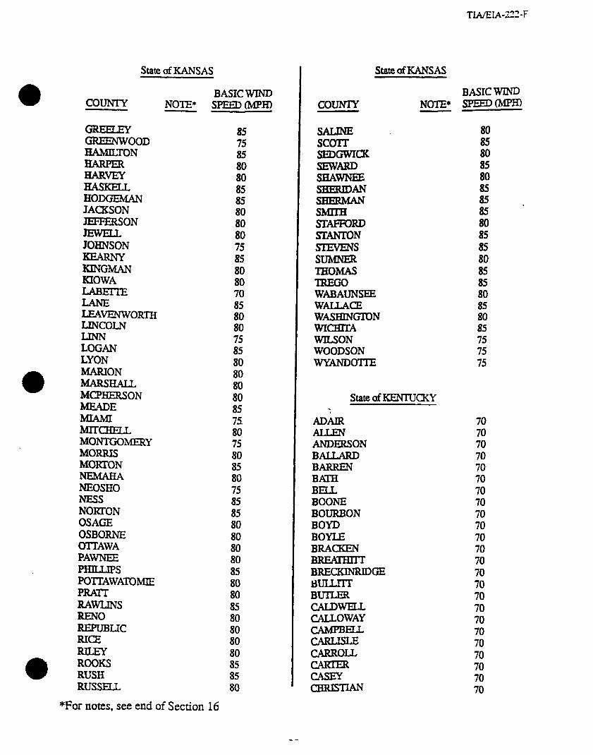
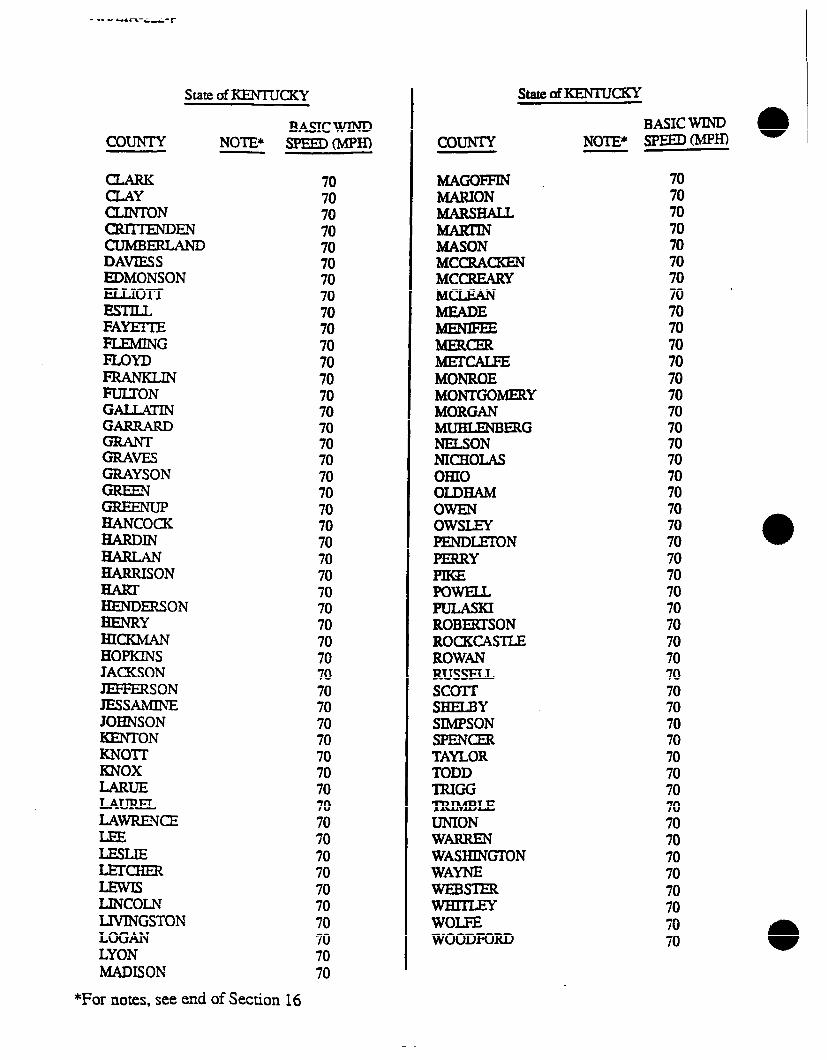
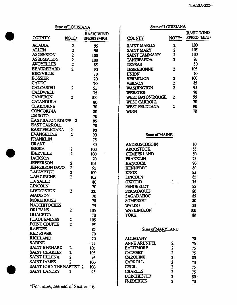
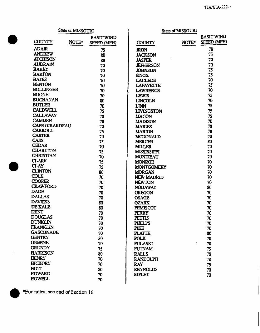
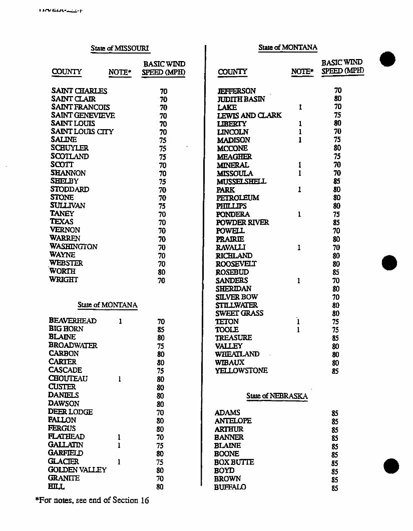
16 COUNTY LISTINGS OF MINIMUM BASIC WIND SPEEDS (See Annex A)
c0uNl-Y
statf! of ALABAMA
AUTAUGA BALDWIN BARBOUR BIBB BLOUNT BULLOCK BUTLER CALHOUN CHAMBERS CHEROKEE (ZTHIEDN CHOCTAW
E!tt&mE COFFEE COLJ3lXT CONECUH COOSA COVING-l-ON CRENSHAW
DALE DALLAS DEKALB ELMORE EscAMBIA ErowAH FAYEITE
GENEVA
BENRY HOUSTON JACKSON JEFFERSON
LAUDERDALE LAmcE
LIMESTONE LOwNDE!z MACON MADISON MARENGO MARION MARSHALL MOBILE
NOTE*
2
2
2 2
2
2
2 2
2
2
2
2 2
2
BASIC WIND s=ED(Mpm
70 100 75 70 70
ii 70 70 70 70
ii: 70 70 85 70 85
ii 80 70 80 70 70 70 90 70 70 70 90 70 70 80 85 70 70 70 70 70 70 70 75 70 70 75 70 70 95
*For notes, see end of Section 16
StatedALABAMA BASIC WIND
COUNIY NOTE* SPEED(MpH)
MONROE 2 MONTGOMEEtY MORGAN PERRY FICKENS
iEFDOiJ?H 2
RUSSEL SAINTCLAIR SHEBY
tiZ!it~GA TALLAPOOSA TUSCALOOSA WALKER WASHINGION 2 WILCOX 2 WINSTON
- 85 70 70
Ei 75 70 70 * 70 70 70 70 70
; : 70
state of ALASKA
ALEunANIsLANDs ANCHORAGE I=?= BRISTOL BAY DILLINGHAM FAlRBANKS NO. STAR
JUNEAU KENAIFENINSULA KEKEEANGAXEWAY KOBUCK KODIAK ISLAND; WANUSKA-SUSl’INA NOME NORTH SLOPE PRINCEOFWALES SIlKA SKAGWAY-%4KUTfl- ANGOON SOUTHEASTFAIRBANKS VALDEZ-CORDOVA WADEHAMPTON wRANGELt--URG YUKON-KOYUKUK
caution: Mound regicm af Alaskashouidbecxmsidered~ sYpdaiwin.dregions.
110 110 110 105 105 70 80 90
100 95
100 110 80
110 100 100 100
100 70 90
110 90 90
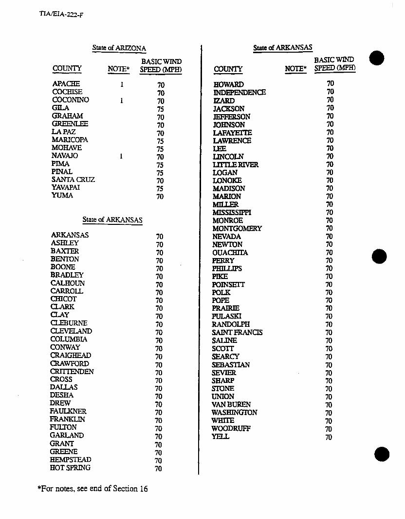
State of ARIZONA
BASIC WIND COUNTY NOTE* mED(MpH)
APACHE 1 COCBlSE cocoNINo 1
FEGAM
LAPAZ MARICOPA MOHAVE NAVAJO 1
PINAL SANTACFUJZ YAVAPAI
State of ARKANSAS
ARKANSAS ASHLEY BAXIER BENTON BOONE BRADLEY CALHOUN CARROLL CBICOT
CLAY
EkG%!E% COLUMBIA CONWAY CRAIGHEAD CRAWFORD CRm-ENDEN CROSS DALLAS DESFIA DREW FAULKNER
FUIXON GARLAND
HEMPSTEAD HOT SPRING
70 70 70
E 70 70 75 75 70 75 75 70 75 70
70 70 70 70 70 , 70 70 70 70 70 70 70 70 70 70 70 70 70 70 70 70 70 70 70 70 70 70 70 70 70
couIvIY
sta!eofARKANsAs BASIC WIND SPEEDWR) NOTE*
HOWARD INDEPENDENCE
JACKSON JEFFERSON JOHNSON WA- LAWRENCE
IJNCOLN LmuzRrvER LOGAN LONOKE MADISON MARION
MISSISSIPPI MONROE MONTGOMERY NEVADA NEWIUN OUACHITA PERRY PHILLIPS
P0Ixm-r PO= POPE
iiiiEsI RANDOLPH sAINrFIuNas SALINE scorr SEARCY SEBASTIAN
EE SroNE UNION VANBUREN WASHINGTON
WOODRUFF
70 70 70 70 70 70 70 70 70 70 70 70 70 70 70 70 70 70 70 70 70 70 70 70 70 70 70 70 70 70 70 70 70 70 70 70 70 70 70 70 70 70 70 70 70
*For notes, see end of Section 16
1 IA/tlA-7”- F
state of CALIF0RNr.A
COUNTY NOTE*
ALAMEDA ALPINE AMADOR BUTTE CALAVEMS COLUSA CONTRA COSTA DELNORTE ELDORADO FRESNO
HUMBOLDT
EEi KINGS
LASSEN LOS ANGELES MADEwi
MARIPOSA MENDocmo MEWED MODOC MONO MONTEREY NAPA NEVADA ORANGE PLACER PLUMAS -IDE SA- SANBWO SANBERNARDINO SANDIEGO sANFRANcIsc0 SAN JOAQUIN SANLUIS OBISPO sANlkulEo SANTABARBARA SANTACLARA SANTACXJZ SHASTA 1 SEE&4 1
a SISKIYOU 1 SOLANO SONOMA
1 1
1
1 1
1 1 1
1 1 1
1
1 1
1
1 1 1
1 1
BASIC WIND SPEED0
70 70 70 75 70 75 70 80 75 70
ii 70 70 70
ii 75 70 70 75
ii: 70 70 70. 70 75 75 70 75 70 70 75 70 70 70 70 70 70 70 70 70 70 75 70 75 75 80
stateafcALIFom
BASIC WIND COUNTY SPEED (MPM NOTE*
state of coLoRAD
ADAMS ALAMOSA ARAPAHOE AR- BACA BENT BOULDER
CLEARCREEK CONEIOS cosm CROWLEY CUSTER DEtTA DENVER DOLORES DOUGLA!3 EAGLE
ET& FREMONT GARFIELD GlLPlN
iiii%iON BINSDALE HUERFANO JACKSON JEFFERSON KIOWA KIT CARSON
LAPLCA
1
1
1
1
1
1
1
1 1
1
1
1
70 75 75 80 70 70 70 75 75
85
ii 70 85 85 85 80 85 85 80 80 85 80 70 85 70 85 80
E 80 80 85 85 75 70
ii
ii 85 80 70 85
*For notes, see end of Section 16
1 lAftlA-7”-t a--
state of COLORADO StateiofFLORIDA
BASIC WIND COuNlY SEED0 NOTE*
LASAMMAS LINCOLN LOGAN MESA
MOFEAT MONTEZUMA MONlROSE MORGm OlERO OURAY PARK PHILLIPS PIIXIN FROWERS PUEBLO RIO BLANC0 RIO GRANDE ROUTT SAGUACHE SANJUAN SANMXGUEL SEDGWICK SUMMIT
1.m WASI-BNGTON
1 80
E 70 75 80 70
ii 85 70
1 80 85 80 85 85
ii 85
1 80 70
ii 1 80 1 85
85 85 85
stare of CONTvEcl-ICUT
FAIRFIELD 2 85 HAKl-FORD 2 80 Lrrm 1.2 80 MIDDLESEX 2 85 NEWHAVEN 2 85 NEWLONDON 2 85 TOLLAND 2 85 WINDHAM 2 85
State of DELAWARE
2 80 NEW CASTLE 2 75 SUSSEX 2 90
Disnict of COLUMBIA
DISTRICTOF COLUMBIA 2 75
COUNTY
ALACEIUA B- . BAY BRADFORD BREVARD BROWARD CALHOUN CHARLOTIE CnRus CLAY COLLIER COLUMBIA DADE DE SOT0 DIXIE DW& ESCAMBIA FLAGLER
GADSDEN GILCHRIST GLADES
HAMILTON HARDEE BENDRY
.IiiERNANDo HIGHLANDS HILLSBOROUGH HOLMES fNDIANRlvEEz JACKSON JEFFERSON LAFAYEI-IE
LEON
LTBERTY MADISON MANATEE MARION
MONROE NASSAU OKALOOSA OKEJXHOBEE
NOTE*
2
1 2 2 2 2 2 2 2 2 2 2
1 2 2 2 2 2 2 2 2 2 2 2 2 2 2 2 2 2 2 2 2 2 2 2 2 2 2 2
;
: 2
BASIC WI-ND SPEED0
95 90
100 95
105 115 100 105 100 95
110 90
115 105 100 95
100 100 105 95 95
100 105 90
100 105 105 100 105 95
105 95 95 95
100 105 95
100 100 95
105 100 105 120 95
1M) 100
*For notes, see end of Section 16

1 l&&IA-~- F
State ofFLORIDA State of GEORGIA
BASIC WIND COUNTY NOTE* sPEEDo COUNIY NOTE*
ORANGE 2 100 OSCEOLA 2 100 PALMBEACH 2 110 PMCO 2 105 PINELLAS 2 105 F0I.K 2 100 PUTNAM 2 95 SAINTJOHNS 2 loo SAINTLUCIE 2 105 SANTA ROSA 2 100 SARASOTA 2 105 SEMINOLE 2 100 SUMTER 2 100 SUWANNEE 2 90 TAmOR 2 100 UNION 2 95 VOLUSIA 2 100 WAKULLA 2 100 WALTON 2 100 WASHINGTON 2 95
State of GEORGIA
APPLING MKINSON BACON BAKER BALDWIN BANKS BARROW BARTOW BENHILL BERRIEN BIBB BLECKLEY BRANTIXY BROOKS BRYAN BULLOCH BURKE BUTTS CALHOUN CAMDEN CANDLER CARROLL CMOOSA -TON
2 2 2 2
2
2 2
2 2
85 .80 85 80 75 75 75 75 80 80 70 75 90 85 90 85 80 70 75 95 80 70 70 90 95
mAHoocHEE (ZHtUTOOGA CBEEIOKEE
CLAY CLAYTON CLJNCH COBB COFFEE c0LQm-r COLUMBIA COOK COWEIA CRAWFORD CRTSP DADE DAWSON DECQUR DEKALB DODGE DOOLY DOUGBEKIY DOUGLAS =Y ECXOLS EFFINGHAM ELBEEa
EVANS FANNIN FAYEITE FLOYD FORSYTH
FULTON
GLASCOCK GLYNN GORDON
K
HABERBAM
HANCOCK HAULSON
BASIC WIND SPEEDm
70 75 70 75 75 70 85 70 * 80 80 75 80 70 70 75 70 75 90 70 75 75 75 70 80 85 90 75 80 85 70 70 70 75 75 70 70 75 95 70 85 75 75 75 75 75 70 70 75 70
*For notes, see end of Section 16
TIAEIA-‘22-F
State of GEORGIA I
COUNTY
HENRY HOUSTON
it--ON JASPER JEFFDAVIS JEFFERSON JENKINS JOHNSON JONES
iI%E LAURENS
LIBERTY LINCOLN LONG LOWNDES LUMPKIN MACON MADISON MARION MCDUFFIE MCINTOSH
MlTcHEu MONROE MONTGOMERY MORGAN MURIUY MUSCOGEE NEWTON OCONEE OGLEl-HORPE PAULDING PEACH PICKENS PIERCE PIKE POLK PULASKI PUTNAM Q- RABUN RANDOLPH RICHMOND ROCKDALE
NOTE*
2
2
2
2
BASIC WIND sPJ330
70
ii 75 75 80 75 80 75 75 70 85 75 75 90 75 90 85 75 70 75 70 75 95 70 80 80 70 80 75 70 70 75 75 75 70 70 75 90 70 70 75 75 75 70 75 75 70
cow EEEN SEMINOLE SPALOING
kFE%F
State of GEORGIA BASIC WIND
NOTE* SPEED (Mm
70
liW3OT -0 3lxrrNALL TAnOR
zEiz% THOMAS
TOOMBS TOWNS
2
2
TROUP
TWIGGS UNION UPSON WAIXER WAIXON
EEEN WASHlNG’IDN WAYNE
itziEz
2 80 2 85
70 75 70 70 70 75 *
2 85 70 80 75 8s 80 85 70 80 70 75 75 70 70 75 75
2 85 75 75
2 90 70
WILCOX
WILKINSON WORTH
80 70 70 75 75 75 75
state OfHAwAlI
HAWAII HONOLULU KAUAI MAUI
80 80
Emi
*For notes, see end of Section 16

state of IDAHO
COuNm
ADA ADAMS BANNOCK BEARLIKE BENEWAH BINGHAM BLAINE BOISE BONNIER BO- BOUNDARY BUTIE CAMAS CANYON CARIBOU CASSIA
CLEARWMER CUSTER ELMORE
FREMONT
GOODING IDAHO JEFFERSON JEROME K00TENAI L.f%rM
Et2 LINCOLN MADISON MINIDOKA NEZPERCE ONEIDA OWYHEE PAYEITE POWER SHOSHONE TETON TWINFALLS VALLEY WASHINGTON
NOTE*
1
I BASIC WIND sPEED(Mpm
70 70 70 75 70 70 70 70 70 75 70 70 70 70 75 70 70 70 70 70 70 75 70 70 70 70 70 70 70 70 70 70 75 70 70 70 70 70 70 70 75 70 70 70
a *For notes, see end of Section 16
state of xLLIN01s BASIC WIND
COUNTY SF'EED(Mpm NOTE*
IzE4DER BOND BOONE BROWN BUREAU CAUIOUN CARROLL
~Z~ELPAIGN CHRISTIAN
.- CLAY CUNTON COXES COOK CRAWFORD CUMBW DEKALB DEWl’IT DOUGLAS DU PAGE EDGAR EDWARDS EFFINGHAM FAYEITE FORD
FULTON GALJXlTV
GRUNDY HAMILTON HANCOCK
iii%i:SON BENRY IROQUOIS JACJLSON JASPER JEFFERSON JERSEY JO DAVIESS JOHNSON
KENDALL KNOX
70 70 70 80 70 75
ii 70 70
ii 70 70 70 75 70 70 75 70 70 75 70 70 70 70 70 70 70 70 70 75 70 75 70 75 75 75 70 70 7@ 70 80 70 75 75 75 75
TIAEIA-222-F
state of ILLINOIS
COUNTY
LASALLE LAWRENCE
LIVINGSTON LOGAN MACON MACOUPIN MADISON MARION MARSHAL;L MASON MASSAC MCDONOUGH MCBEN-RY MCLEAN MENARD MERCER MONROE MONTGOMERY MORGAN MOULIRIE OGLE PEmIA PERRY PIAIT PIKE POPE PULASKI PUTNAM RANDOLPH
kG SAINTCL4IR SALINE SANGAMON SCHLJYBZ SCOTT SHEIJ3Y STARK STEPHENSON TAZEWELL UNION VERMILION WABASH WARRJ3 WASHINGTON WAYNE
BASIC WIND NOTE* SPEED0
1 80 75 70 75 75 70 70 70 70 70 75 70 70 70 80 70 70 75 70 70 70
ii: 75 70 70 70 70 70 75 70 70 75 70 70 70 70 70 70 75 80 70 70 70 70
; 70 70
stateoflLLINoIs
BASIC WIND
CouNn NOTE* SPE’EDWm
WHITESIDE 80
%AMSON 75 70
WINNEBAGO 80 WOODFORD 75
StatedINDIANA
ADAMS
BARTHOLOMEW BENTON BLACKFORD BOONE BROWN CARROLL CASS
E&ON CRAWFORD DAVIESS DEARBORN DECQTJR DEXAL33 DELAWARE DUBOIS
FAYEI-IE FLOYD FOUNTAJN
FUIXON GIBSON
EEk HAMIIXON HANCOCK HARRISON HENDRxcKs HENRY HOWARD HUNTINGION JACKSON JASPER JAY JERER!ZON JENNINGS JOHNSON
75 75 70 75 70 70 70 70 75 70 70 70 70 70 70 70 75 70 70 75 70 70 70 70 75 70 70 70 70 70 70 70 70 70 75 70 75 70 70 70 70
*For notes, see end of Section 16

State ofINDIANA
BASIC WIND COUNTY NOTE* SPEED0 KNOX KoscIusKo LAPORTE LAGRANGE
LAWRENCE MADISON MARION MARS=
iEkE? MONROE MONTGOMERY MORGAN NEWTON NOBLE OHIO ORANGE OWEN PARKE PERRY PIKE
e PORTER POSEY PULASKI mAM RANDOLPH
RUSH ST. JOSEPH SCOTT SI3Eu3Y SPENCER STARKE STEUBEN SULLIVAN S- TIPPECANOE TIPTON UNION VANDERBURGH VERMIIUON VIGO WABASH WARREN WARRICK WASHINGTON
70 75
1 75 75
1 75 70 70 70 75 70 75 70 70 70 75 75 70 70 70 70 70 70
1 75 70 75 70 70 70 70 75
:8 70 75 75 70 70 70 70 70 70 70 70 75 70 70 70 70 WAYNE
*For notes, see end of Section 16
; TIAEIA-222-F
StatedINDIANA BASIC WIND
COUNTY NOTE* SF=D(MpH)
State af IOWA
ADAXR 2i?izLE . APPANoosE AUDUBON BENTON BLACKHAWK BOONE BREh4ER BUCHANAN BUENAVISTA BUTLER CALHOUN CARROLL CASS WAR cER.RoGoRDo -0KEE CHICKASAW CLARKE CLAY CLAYTON CLINTON ClUWFORD DALLAS DAVIS DECAI’UR DELAWARE DES MOINES DICKINSON DUBUQUE
ft%EE FLOYD
FREMONT
GRUNDY
ZN HANcocK
80 80
Fl 80 80
ii 80 80 80 80 80 80 80 80 80 80 80 80 80 80 80 80 80 75 80 80 75 80 80 80 80 80 80 80
ix 80 80 80

TlAIEIA-221-F
State of IOWA
COUNTY
HARDIN HARRISON HENRY HOWARD HUMBOLDT IDA IOWA JACKSON JASPER JEFFERSON JOHNSON JONES KEOKUK KossuIH
LOUISA LUCAS LYON MADISON MAHASKA MARION MARSHALL
MITCBELL MONONA MONROE MONTGOMERY MWXKINE O’BRIEN OSCEOLA PACE PALO ALTO PLYMOUTH POC4HONTAS POLK
BASIC WIND NOTE* sPEEDch4Pm
POTTAWAmAMlE P0wl3HlEK RINGGOLD SAC SCOTr SHELBY SIOUX STORY TAMA TAnOR UNION VANBUREN WAPEILO
*For notes, see end of Section 16
75 80 80 80 80 80 80 80 80 80 80 80 75 80 75 80 85 80 80 80 80 80 80 80 80 80 80 80
ii 80
ix 80 80 80
;z 80 80 85 80 80 80 80 75 80
State dIOWA
BASIC WIND COUNTY NOTE* SPEEDWH)
WARREN WASHINGTON WAYNE WEBSTER WJNNBBAGQ WINNES- WOQDBURY WOKm WRIGHT
State &KANSAS
.
ANDERSON AKHISON BARBBR BARH3N BOURBON BROWN BUILBR CHASE CHATAUQUA CHEROKEE
EEED
EiEkBE COWLJZY CRAWFORD DECATUR DICKINSON DONIPHAN DOUGLAS EDWARDS
Es mLswoRlH
75
iFi 80 80 70 80 80 80 75 70 85 80 80 80 75 80 80 70
ii: 80 80 80
ii: 80 85 85 75 80 85 85 85 85
State of KANSAS
BASIC WIND COUNIY NOTE* SPEED0
=OD 85 75
HAMILTON ii
iiEE 80 85
HODGA4AN 85 JACKSON 80 JEFFERSON
xi JOHNSON 75
85 KINGMAN 80 KIOWA 80 LABErIE 70
=VJZNWORTH ii LINCOLN 80 2i.N 75
85 LYON 80 MARION MARSHALL MCPHERSON MEADE
iEG!iaL MONTGOMERY MORRIS MORTON
NEOSHO NESS NOKI’ON OSAGE OSBORNE C7ITAWA PAWNEE PHILuPS POTI-AWATOMIE
RAWUNS RENO REPUBLIC RICE
ROOKS RUSH
80 80 80 85 75. 80 75 80 85 80 75 85 85 80 80 80 80 85 80 80 85 80 80 80 80 85 85
RUSSELL 80
*For notes, see end of Section 16
State uf KANSAS
BASIC WIND COUNTY NOTE* SPEED(MpH)
EEiORD STANTON STEVENS
IHOMAS TREGO WABAUNSEE WUCE WASHING’IDN WI-A WILSON WOODSON WYANDm
state of KENTCJCKY .
ADAIR
ANDERSON BALLARD BARREN BPilH BELL BOONE BOURBON BOYD BOYLE BRACKEN BRJXBllT BRECKINRIDGE J3~ll-r BUTLER
gk?zE
gz?iE CARROLL
EiF cHRETIAN
80 85 80 85 80 85 85 .
ii 85
ii 85 85 80 85 80 85 75 75 75
70 70 70 70 70 70 70 70 70 70 70 70 70 70 70 70 70 70 70 70 70 70 70 70
--
- -- I rrr\-;,-r
state OfKENTIJcKY
BASIC WIND COUNTY NOTE* SPEEDt-Mm
EF 70 70 CLINTON cxrITmDEN : CUMBERLAND 70 DAVIESS 70 EDMONSON 70 ELIOTI- 70
70 FAYFI-IE 70 FLEMlNG 70 FLOYD 70
70 FUIXON 70 GALILMTN 70 GARR4RD 70 zz 70 70
GRAYSON 70 ziEh.JP 70 70
HANCOCK 70 HARDIN 70
70 HARRISON 70
70 BENDERSON 70 BENRY 70 BICKMAN 70 HOPKINS 70 JACKSON 70 JEFFERSON 70 JESSAMINE 70 JOHNSON 70 KENTON 70 KNOTT 70 KNOX 70 LARUE 70 LAUREL 70 LAWRENCE 70
70 LESLIE 70 LErcHER 70
70 LINCOLN 70 LMNGSTON 70 LOGAN 70 LYON 70 MADISON 70
*For notes, see end of Section 16
ScateOfICENRJ=Ky
COUNTY
MAGoFFIN MARION MARsHAu
MASON MCCRACKEN MCCREARY MCLJXN
iiE!EE MERCER MErm MONROE MONTGOMERY MORGAN MUHLENBERG NESON NICHOLAS OHIO OLDHAM
iEzi!EY PENDLETON PERRY
RYXELL PULASKI ROBERTSON ROCKCASTLE ROWAN RUSSELL SCOTr SHELBY SIMPSON SPENCER TAYLOR TODD TRIGG TRIMBIX UNION WARREN WASmGTON WAYNE WEBSTER
WOLFE WOODFORD
BASIC WIND NOTE* SPEEDtMPH)
TIAIEIA-222-F
StateofLOlJISIANA
COUNTY NOTE*
ACADIA 2 2
ASCENSION ASSUMPI-ION i AVOYELLES 2 m2AmAR.D 2 BlJ3MLLE BOSSIER CADDO CALCASIEU 2 CALDWELL CAMERON 2 CAIAHOULA CIAIBORNE CONCORDIA DE SOT0 EAST BATON ROUGE 2 EAST CARROE EASTFELICIANA 2 EVMGELINE 2
IBERIA 2 IBEwILLE 2 JACKSON JEFFERSON -ONDAVIS 2 LAEAYEmZ 2 LAPOURCBE 2 LASALLE LINCOLN LIVINGSTON 2 MADISON MOREHOUSE NiUCBITOCHES ORLEANS 2 OUACBlTA PLAQUEMIDEZ 2 PolNTcouPEE 2 RAPIDES REDRIVER RICBLAND SABINE SAINTBERNARD 2 SAINTCHARLES 2 SAINT-A SAJNTJAMES
BASIC WIND =oMpR)
95
1z loo 85 90 70 70 70 95 75
100 80
ii 70 95
ii 90
iii 100 loo 70
105 95
100 105 80 70
100 70 70 75
105 70
105 95 85 70 70 75
105 105 95
100 SAINTJOBNTBEBAFTIST 2 100 SAINTLANDRY 2 95
*For notes, see end of Section 16
StareofLOUISIANA
BASICWXND COUNTY SPEED(MpH) NOTE*
sAIlwMAK13N 2 100 SAINTMARY 105 SAINTTAZMMANY ; 100 TANciIpAHOA 2 TENSAS ii TERREBONNE 2 105 UNION 70 -ON 2 100 VERNON 85 WASBINGTON ; 95
Z~Z~~%NROUGE 2 ii wEsTc4RRoLL WESTFELICIANA 2 ii
70
State OfMAINE
ANDROSCOGGIN AROO!XOOK CLJMBERLAND
BArycocK KENNEBEC KNOX LINCOLN OXFORD PENOBSCOT PIS~AQUIS SAGADAIIOC SOMERsEr WALDO WASBINGTON YORK
80 85 80 75 90 80 85 85
1 . 75 85 80 85 80 85
100 80
StatedMARYLAND
ALIEANY ANNEARUNDEL 2 BALXIMORE 2 CAL= 2 CAROLINE 2 CARROLL 2 CEaL 2
2 DORCBES-XER 2 PREDERICK 2
70 75 75 75 80 70 75 75 80 70

TlA/ELW22-F
state OfMttRYLAND StateofMICHlGAN
BASIC WIND COUNTY NOTE* SPEED0
GARREIT HARFORD HOWARD
MONTGOMERY PRINCE GEORGE’S
ZEf?kEF: .
SOMERsEr TALBOT WASHINGTON wIcoMlc0 WORCBSTER
2 2 2 2 2 2 2 2 2 2 2 2
State of MASSACHUSETTS
BARNSTABLE 2 BERKSHIRE 12 BRISTOL 2 DUKES 2 ESSEX 2
1.2 HAMPDEN 2 HAMPSHIRE 2 MIDDLESEX 2 NANTUtXET 2 NORFOLK 2 PLm0Ul-H 2 SUFFOLK 2 WORCESTER 2
State of MICHIGAN
ALCONA 1 ALGER 1 ALlEGAN 1 ALPBNA 1
1 ARBNAC 1 BARAGA 1 BARRY BAY 1 BHNZIE 1 BERRJEN 1 BRANCH CALHOUN CASS
*For notes, see end of Section 16
;i 70 75 70 75 75
E 80
ii 90
100 70 90
iii
ii 75 90
105 90 95 90 85
75 75 75 75 75 75 75 75 75 80 75 75 75 75
COUNTY NOTE*
cHARLEvolx 1 CHEBOYGAN 1 CBIPPBWA 1
CLJNTON QRAWPORD Dn DICKINSON
iEi& 1
iik?iiiY GRANDTMvERsE G&SHOT HJLLSDALE HOUGHTON HURON INGHAM IONIA IOSCO IRON ISABELLA JACKSON -00
1 1
1 1
1
KEWEENAW
LAPEER LEIZANAU LENAWEE LIVINGSTON LUCE MACKINAC MACOMB
iizgEIE MASON MECOSTA MENOMINE MIDLAND MISSAUKEE MONROE MONT.CALM MONTMORENCY MUSKEGON NEWAYGO OAKLAND
1
1 1
1
BASIC WIND SPEED0
; 70 75 75
ii 80 ’ 75
E
E 75 75 75 70 75 75 75
ii 75 75 75 75 75 70 80
ii 75 75 70 75 75 80 80 80
ii 75 75 75 75 75 80 80 75

State of MXCHlGAN BASIC WIND
COuNrY NOTE* spEED(MpH)
OCEANA OGEMAW ONTONAGON OSCEOA OSCODA OTSEGO OTTAWA PRESQUEISLE ROSCOMMON SAGINAW SAINTCLUR SAINT JOSEPH SANTLAC SCHOOL CEuFr SHIAWASSEE TUSCOLA VANBUREN WMH’IENAW WAYT+JE WEXFORD
1
1
1 1
1 1
1 1
1 1
Statedm0~~
ANOKA BECKER BELXRAMI BENTON BIG STONE BLUEEARTH BROWN CARLXON CARVER
iii%kWA CHISAGO
ERWMER COOK COTIONWOOD CROWWING DAKOTA DODGE DOUGLAS FARIBAUEI’ FILUAORE FREEBORN GOODHUE
80 75 75 75
; 80 75 75
;
z 80
E
iz
ii
ii 85 80 80 90 80 80
1 ii
iz 75 90 80 70 85
i: 80 85 80
ii
ii 80
*For notes, see end of Section 16
TIA/EIA-222-F
State dMINNESOTA
BASIC WIND COUNIY NOTE* SPEs>(MpH)
HOUSTON -ARD .
EE JACKSON KANABEC IMNDIYOBI KrITSON KOOCHKHING LACQUIPiUUE
LAKE OF TEE WOODS LE!mErJR LINCOLN LYON - MAHNOMEN MARS=
MCLEOD
MlLLELAcs MORRISON MOWER MURRAY NIcouEr NO&ES NORMAN OLMSIED OTIERTAIL PENNINGION
PIPESTONE POLK
EEEY REDLAKE REDWOOD
RICE ROCK ROSEAU sAlNTLouIs SCOIT SHERBURNE SIBLEY
.?i-zz? SEVENS
TODD TIMERSE
85 80 80 75 80 80
iFI .
ii 75 75 80 85 85
8”o 80
ii 80 80 80 85 80
:z 80
ii:
ii: 85 85 80 80 85 80 80
Yz 1
ii 80
ii
iti 85
E

State of h4lNNESOTA
BASIC WIND COUNTY NOTE* SPEEDWH)
WABASHA WmENA WASECA WASBINGTON wmoNwAN
EE4 WRIGHT YELL0wh4ED1cINE
80 80 80
ii:
ii 80 85
state of MISSISSIPPI
ADAMS 80 ALCORN
2 ii KITilLA BENTON zi BOLTVAR 70 CALHOUN CARROLL ;i CBICKASAW 70 CHO(JTAW 70 CIAIE3ORNE 75
2 CLAY $ coAHoMA 70 COPIAH 80 COVINGTON 2 80 DE SOT0 70 FORREST 2 90
2 85 GEORGE 2
2 ii GRENADA 70 HANCOCK 2 100 HARRISON 2 100 HINDS 75 HOLMES 70 HUMPHREYS 70 ISSAQUENA 70 lTAWAMBA 70 JAQCSON 2 100 JASPER 75 JEFFERSON 80 JEFFERSONDAVIS 2 85 JONES 2 85
70 LAFAYEITE 70
2 90 LAuDEflDALE 75
*For notes, see end of Section 16
COUNTY
E&E IJNCOLN LOWNDES MADISON MARION MARSHALL MONROE MONTGOMERY NESHOBA NEWTON NOXCJBEE OKTIEBEHA PANOLA PEARLRIvER PERRY
EOTOC PRENTISS Q-
scolT SHARKEY SIMPSON SMIIH STONE SUIWXOWER TALLxmTcHlE Tm TIePAH TISHOMINGO TUN-ICA UNION WAJXHALL WARREN WASHINGION WAYNE
CN WINSTON YALOBUSHA wzoo
state ufMx!sIssIPP1
BASIC WIND NOTE* SPEED0
2 85 70 70 70
2 85 70
2 z 70 70 70 70 75 70 70 70
2 2 ii 2 90
70 70 70 75 75 70 80 75
2 95 70 70 70 70 70 70 70
2 90 70 70
2 85 70
2 90 70 70 70
state of MISSOURI
COUNTY NOTE*
AT'CBISON AUDRAIN BARRY BARTON BAIES BENTON BOLLlNGER BOONE BUCHANAN BUTLER CALDm CALLAWAY CAMDEN CAPEGIRARDEAU CARROLL
CASS
ZON
CLAY cLINKIN COLE COOPER CRAWFORD DADE DALI& DAVIEZS DEKALB DENT DOUGLAS DUNKLIN
EiitE!%E GENTRY
GRUNDY HARRISON HENRY HICKORY HOIX HOWARD HOWELL
BASIC WIND SPEEDtMnD
75 80 80 70 70 70 70 70 70
3 70 75 70 70 70 75
R 70 75 70 75 75 80 70 70 70 70 70
ii: 70 70 70 70 70 80 70 75 80 70 70 80 70 70
stalebofMIssouRI
COuNlY NOTE*
IRON JACKSON
ZON JOHNSON KNOX LACLEDE L/WA- LAWRENCE
LINCOLN
E%s-I~N MACON MADISON
ESJ MCDONALD MERCER
MISSISSIPPI MONIlEAU MONROE MONTGOMERY MORGAN NEWMADRID NEWTON NODAWAY OREGON OSAGE OZARK PEMISCOT
EiEi PHELPS
POLK
PUTNAM
luNDoLPH RAY REYNOLDS
BASIC WIND SPEED0
70 75 70 70 75 75 70
E
ii 75 75 75 70 70 70 70 80 70 70 70 70 70 70 70 70 80 70 70 70 70 70 70 70
iii 70 70 75 70 70 75 70 70
a *For notes, see end of Section 16
1 Irv Cl&-&-t
state ofMIssouRI
BASIC WIND COUNTY NOTE* SPEED0
SAINTCHARLES SAINTCLUR sAINTFRANcoIs SAINTGENEVEW SAINT LOUIS SAINTLOUIS CrIY SAWBE
3z Sal-T SHANNON SBELBY STODDAEtD
iEz!kJ
EE VERNON WlRREN WASHINGTON WAYNE .-= WORTH WRIGHr
StateofMONTANA
BEAVERBEAD I BIG HORN BLAINE BROADWm CARBON
EEEiE cHouIEAu 1 CUSTER DANIELS DAWSON DEERLODGE FAILON FERGUS
1 GAIJAIN 1
EiiEE? 1 GOLDENVALLEY
70 70 70 70 70 70 75 75 . 75 70 70 75 70 70 75
ii 70 70 70
zi 80 70
70
ii 75 80 80 75
ii 80 80 70 80 80 70
iii 75 80
2
StatedMONTANA
BASIC m NOTE* SPED(MpM COUNIY
JEFFERSON JUDII-HBASIN
ELNDCLARK LJBEKE LINCOLN MADISON MCCONE MEAGHER
iiiiEE4 Mus- PARK PEIROLEUM PHIlUPS PoNDEm POWDERRIVER KwELL
RAVALU RICBLAND ROOSEVEU ROSEBUD
ziiE!Ek SILVERBOW SITEWAIER SWEIXGRASS WON Tool-E TREASURE
gggm, WIBAUX YELLOWSTONE
1
1
1
‘1 1
state of NEBRASKA
70 80 70 75 80
ii 80 75 70 70 85 80
ii
;z 70 80 70 80 80 85 70 80 70 80 80 75 75 85 80 80
ii
BANNER BIdUNE BOONE BOXBU’ITE BOYD BROWN BUFFALO
: 85 85 85
i; 85
*For notes, see end of Section 16
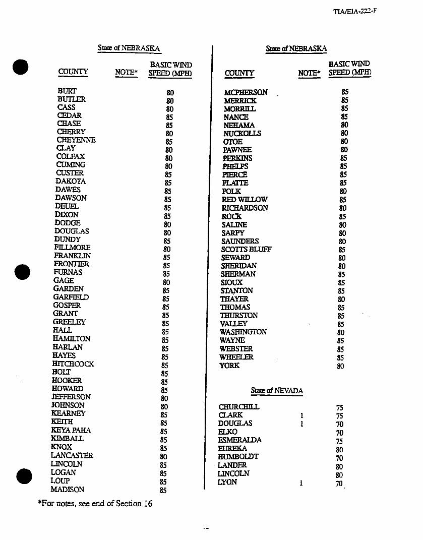
COUNTY
BURT BUTLER CASS CEDAR CHASE
EiEFzkE CLAY coIx4x
EKE? DAKOTA DAWES DAWSON DEUEL DIXON DODGE DOUGLAS DUNDY FILLMORE
FRONTER FURNAS GAGE GARDEN GARFIELD GOSPER
GREELEY
ii%i~T0~
HAYES HITCHCOCK HOIX HOOKER HOWARD EFFER!SON JOHNSON
KEYA PAHA KlMBALL KNOX LANCASTER LINCOLN LOGAN LOUP MADISON
StateofNEBRASIcA
BASICWIND spEED0vfPH-l NOTE*
80 80 80 85 85 80 85
ii
ii
E 85 85
ii 80
ii 85
iz 80 85 85 85 85
ii;
: 85
ii: 85 85 80
ii 85 85 85
ifI 85 85 85 85
*For notes, see end of Section 16
T.wEIA-222-F
StatelTfNEWUSKA
COUNTY
MCPBERSON MERRICK MORRILL NANCE
NUCKOIU OTOE PAWNEE
PBELPS PERCE
POLK REDwILulW RICHARDSON ROCK SALINE SARPY SAUNDERS SCOITS BLUFF
iikz%zN SHERMAN SIOUX SlApON THAYER THOMAS THURSTON VAlXZY WASHING’TON WAYNE wEB!nER
YORK
BASIC WIND NOTE* SPEED(MpH)
ii
ii
5 80 80 85 85 85 85 80 85 80
ii 80 80 85
ii: 85
iz 80
g '. 85 80 85 85 85 80
%teofNEVADA
CHURCHILL 1
DOUGLAS 1 ELXO ESMERALDA
HUMBOLDT .LANDER IJNCOLN LYON
75
;i 70 75 80 70 80 80 70
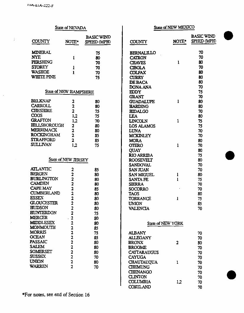
Stare c&NEVADA
BASIC WIND COUNTY NOTE* sPEED(Mpm
1 70
SlmEY 1 70 WASHOE 1 70 WBIIEPINE 75
s~of~HAMPsHlR.E
BEIXNAP CARROLL CHESHIRE coos -ON HILLSBOROUGH MERRIMACK ROCKINGHAM sTRAFFoRD SULLIVAN
2 2 2 12 12 2 2 2 2 12
80 80
; 70
:: 85 85 75
state of NEW JEEtsEY
fXIUNTIC BERGEN BURLINGTON
EEilY CUMBERLAND ESSEX GLOUCESTER HUDSON HUNTERDON MERCER MIDDLESEX MONMOUTH MORRIS OCEAN PASSAIC SALEM SOrvlEluEr SUSSEX UNION WARREN
2 85 2 80 2 80 2 80 2 85 2 80 2 80 2 2 f ii 2 75 2 80 2 80 2 85 2 75 2 2 ifi 2 80 2 80 2 70 2 80 2 70
COUNTY
BERNALILLO CKtRON cHAvl3 UBOLA COLFM CURRY DEBACA DONAANA EDDY
tiEE!iLuPE HARDING HIDALGO
LmcoLN Los ALAMOS LUNA MCKINLEY MORA OIERO QUAY RIO ARRIBA ROOSEVETX SANDOVAL SANJUAN SANMJGUEL SANTAFE SlEEUZA SOCORRO TAOS TORRANCE UNION VALENCIA
stateofNEwh4ExIco
BASIC WIND NOTE* SF’EED(MpH)
70
ii 70 80 80 80 70 75 70
1 ii
ii 1 75
;i 70 80
1 70 80 75 80 70 70
1 80 1 75
70 70 80
1 75 85 70
stateofNEwY0R.K
ALBANY AILEGANY BRONX 2 BROOME ~ARAUGUS CAYUGA CHAUTAUQUA 1 CBEMUNG CHENANGO CLINTON COLUMBIA 12 CORTLAND
70
ix 70 70 70 70 70 70 70 70 70
*For notes, see end of Section 16
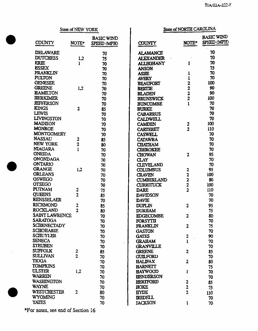
COUNTY
stareofNEwYoRK State c&NORTH CAROIJNA
DELAWARE DUTCBESS
ESSEX
HAMILTON
iiiEi%J KINGS
LIVINGSTON MADISON MONROE MONTGOMERY NASSAU NEW YORK NIAGARA ONEIDA ONONDAGA ONTiwO ORANGE ORLEANS 0swEGo OTSEGO
F$ziir RENSSELAER RICHMOND ROCKLAND
NOTE*
12 1
12
2
2 2 1
12
2 2
2 2
SAINTLAWRENCE SARATOGA ScBENEcI=ADY scHoHARIE SCHUYLER SENECA STEUBEN SUFFOLK 2 SULLIVAN 2 TIOGA TOMPKINS
kifizzk 1.2
WASHMZTON WAYNE WESTCHESTER 2 WYOMING Ym
BASIC WIND SPEEoMPm
70 70 70 70
;
;:
ii 70 70 70 70 70 85 80 70 70 70 70 70 70 70 70
ii: 70 85 80 70 70 70 70 70 70 70 85 70 70 70 70 70 70 70 80 70 70
COUNTY
ANSON
AVERY BEAUFOIU BEKllE BLADEN BRUNSWICK BUNCOMBE BURKE CABARRUS CALDWELL CAMDEN
EitfEsF CMAWBA
CHEROKEE CHOWS
Ei%LAND COLUMBUS cm.. CUMBERLAND CURRIIUCK DARE DAVIDSON DAvlE DUPLIN DURHAM BDGECOMBE FORSYTH
GASTON
iiiE?iM
iiisziw
iizis% HAYWOOD HENDERSON HEEZTFORD HOKE HYDE IREDELL JACKSON
BASIC WIND -(MPH) NOTE*
1
1 1 2 2
2" 1
2 .2
2
2 2 2 2 2
2
2
2
9
70 70 70 75 70 70
100
ii loo 70 70 70 70
100 110 70 70 70 70 95 70 70 95
loo 80
loo 110 70 70 95 75 80 70 75 70 90 L
1 70 70
2 85 70
2 80 75
1 70 70
2 85
: 75
110 70
1 70
*For notes, see end of Section 16

State ofNORTH CAROLINA
COUNTY NOTE*
JOHNSTON JONES
LENOIR LINCOLN MACON MADISON
MCDOWELL MECKLENBURG MrrcHELL MONTGOMERY MOORE NASH NEwHANovER NORTHAMPTON ONSLOW ORANGE PAMLICO PAsQUOTANK PENDER PERQUIMANS PERSON PlTT POLK RAM>OLPH RICHMOND ROBESON ROCKINGHAM ROWAN RUTHEXFORD SAMPSON SCOTLAND STANLY STOKES suRRY SWAIN TFaNsYLvANIA
UNION VANCE WAKE WARREN WASBINGTON WMAUGA WAYNE
WIUON YADIUN YANCEY
2 2
2
1 1 2
1
2 2 2 2
2 2
f
2
2
2 2
1
2
2
2 2 1 2
2
1
BASIC WIND SPEED0
80 100
iii 70 70 70 90 70 70 70 70
lli 105 80
100 70
105 95
100 95 70 90 70 70 75 80 70 70 70 85 80 70 70 70 70 70
loo 70 75 75 75
100 70 85 70 80 70 70
I
COUNTY
ADAMS BARNES BENSON BIKJNGS BOTTTNEAU BOWMAN BURKE BURLEIGH CASS CAVAWER DID DIVIDE DUNN EDDY EMMONS FOSTER GOLDENVALLEY GRAND FORKS
EiZ BEITINGER KIDDER LAMOURE LOGAN MCBENRY MCINTOSH MCKENZIE MCLEAN MERCER MORTON MOUNTRAlL NELSON OLIVER PEMBINA PIERCE RAMSEY RANSOM
RICHLAND ROLEI-IE SARGENT SHERIDAN SIOUX SLOPE
EiE STUTSMAN TOWNER
WALSH
State of NORTH DAKOTA
BASICWIND NOTE* SPEED0 -.
80
ii 80
ii
ifi 85 75 85
; 80 80 80
ii 75 80 80 80 80 80 75 80 80 75 75 75 75 80 75 80 75
ii 75 90 75 90 75 80 80 80 80 80 75
II;
*For notes, see end of Section 16
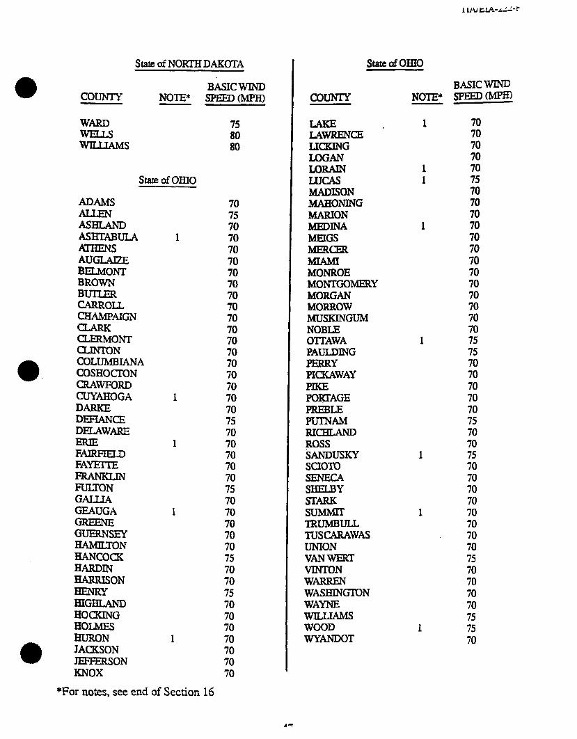
State of NORTHDAKOTA
BASIC WIND COUNIY NOTE* -0MpH)
EtEi 75
WILLIAMS
state OfoBJo
ADAMS
ASHLAND ASHTABULA Al-HENS AUGLAQE BELMONT BROWN
EEL CHAMPAIGN
EEEONT CLINTON COLUMBIANA COSHOaON cluwFoRD CUYAHOGA DARKE DEFiANCE DELAWARE
FAIRFIELD FAYEiTE
FiJITON GALLIA QAUGA
Es&Y HAMILTON HANCOCK
%%!3N HENRY HIGHLAND HOCKING HOLMES BURON JACKSON JEFFERSON KNOX
70 75 70
1 70 70 70 70 70 70 70 70
;: 70 70 70 70
1 70 70 75 70
1 70 70 70 70 75 70
1 70 70 70 70 75 70 70 75 70 70 70
1 70 70 70 70
Stateo.f0BI0
COUNTY NOTE*
1
LICKING LOGAN limAIN LUCAS MADISON MAHONING MARION MEDINA MEIGS IbEEKER
MONROE MONTGOMISY MORGAN MORROW MusKINGuM NOBLE O’ITAWA PAULDING PERRY PImWAY
POWAGE PREBLE PUTNAM RI- ROSS SANDUSKY sclom SENECA SHELBY STARK
TRUMBULL TUSCARAWAS UNION VANWERT VINTON WARREN WASHINGTON WAYNE
WOOD WYANDOT
1
BASIC WIND SPEED0
; 70 70 70 75 70 70 70 70 70 70 70 70 70 70 70 70 70 75 75 70 70 70 70 70 75 70 70 75 70 70 70 70 70 70 70 70 75 70 70 70 70 75 75 70
*For notes, see end of Section 16
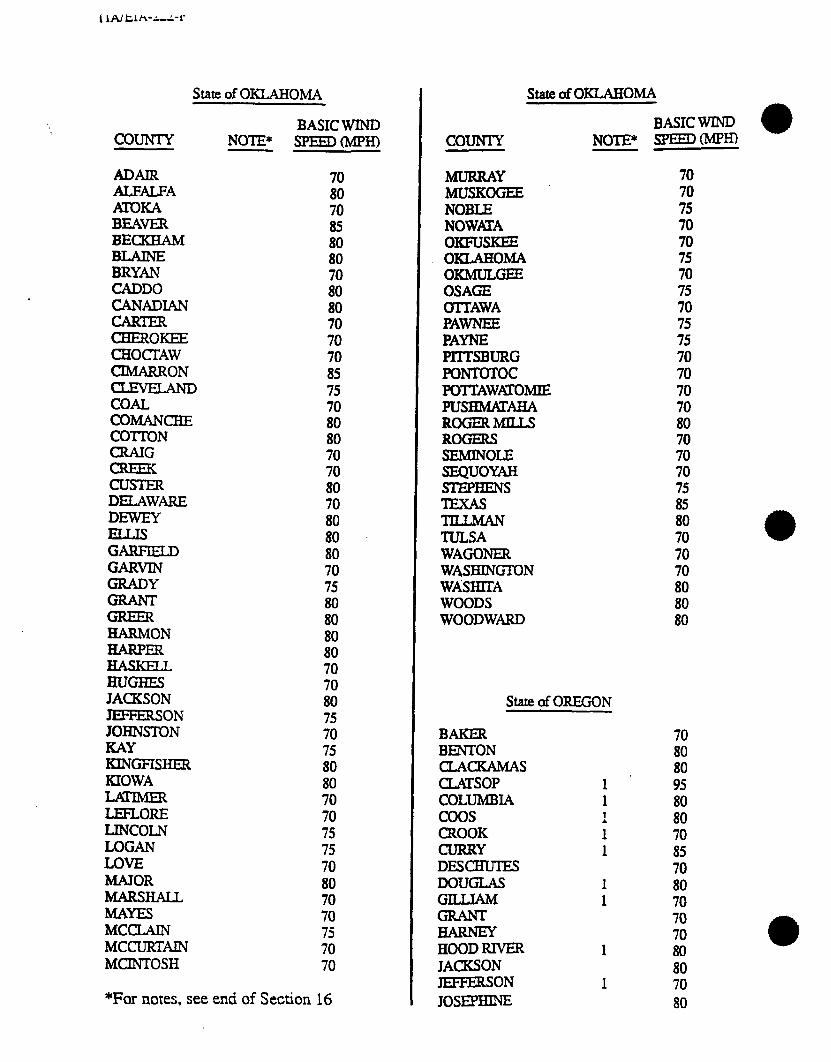
[ IA/ tln-A,A-r
state of OKLAHOMA
COIJNTY
ADAJR ALFALFA ATOKA BEAKR BECKHAM
EE CADDO CANADIAN
tiiEE&E CHOClYAW CIMARRON
COAL COMANCHE COT’IDN
z CUSTER DELAWARE DEWEY
GARFED GARVIN GRADY
HARMON HARPER HASKELL HUGHES JACKSON JEFFEXON JOHNSTON KAY KINGFISHER KIOWA
IEFLORE LINCOLN LOGAN LOVE MAJOR MARSHALL MAYES MCUAIN MXUEEAIN MCINTOSH
BASIC WIND NOTE* ~(MPH)
70 80 70 85 80 80
ii 80 70 70 70 85 75 70 80 80 70 70 80
;!I 80 80 70 75 80 80 80 80 70 70 80 75 70 75 80 80 70 70 75 75 70 80 70 70 75 70 70
*For notes. see end of Section 16
stateofoKLAHoMA
BASIC WIND NO-E* SPEEDWH) COUNTY
MURRAY MUSKOGEE NOBLE NOWHA 0KFusKEE OKMHOMA OKMULGEE OSAGE OlTI’AWA PAWNEE PAYNE PIITSBURG FONTOTOC POnAWp;ToMIE PUSBMATAHA ROGER h4IUS ROGERS SEMINOLE SEQUOYM !TIEPBENS
iFi?LN TULSA WAGONER WASHINGlON WA’SHITA WOODS WOODWARD
State of OREGON
BAKER BENTON CLACKAMAS CLATSOP COLUMBIA coos CROOK CURRY DESCHUIES DOUGLAS GILLIAM
HOOD RIVER 1 JACKSON JEFFERSON 1 JOS=
70 70 75 70 70
; 75 70 75 75 70 70 70 70 80 70 70 70
iiz 80 70 70
ii 80 80
70 80 80 95 80 80 70 85 70 80 70 70 70 80 80 70 80
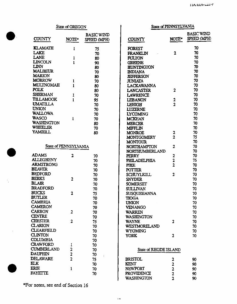
COUNTY NOTE*
State of OREGON
LINCOLN
MARION MORROW MULTN0MA.H POLK SHEEMAN ‘I’LLAMOOK UMATILLA UN-ION WAUOWA WASCO WASHINGTON
1
1 1
1 1
1 1
1
BASIC WIND SPEEDCMP~
75 70 80 90 80
iii 70 80 80
ii! 70 70 70 70 80 70 80
*
State! 0fPENNSYLVAMA
ADAMS 2 ALLEGHENY ARMSTRONG BEAVER BEDFORD BERKS BLAIR BRADFORD BUCKS BUILER CAMBRIA CAMERON CARBON
CHESTER CLARION
CLINTON COLUMBIA CRAWFORD CUMBERLAND DAUPHtN DELAWARE
a FAYEI-IE
2
2
2
2
70 70 70 70 70 70 70 70 75 70 70 70 70 70 75 70 70 70 70 70 70 70 . 75 70 70 70
1ltL l2A-d”- t
state dPENNsYLvm
COUNTY NOTE*
FOREST l%lNKLm 2
flEz!i HUNTINmN INDIANA JEFFERSON =A LXKAWANNA LANCASTER 2 LAWRENCE LEBANON 2
EEEE 2
LYCOMING MCKEAN MERCER
MONROE 2 MONTGOhIEEtY 2 MONTOUR NO-N 2 NORI'HUMB- PERRY 2 PBILADELPIHA 2
2 POTIER S- 2 SNYDER SOMERsEr SULLIVAN SUSQUEEiANNA TIOGA UNION VENANGO WARREN WASI3IN~N WAYNE 2 WESTMOW WYOMING YORK 2
State of RHODE ISLAND
BRISTOL 2 2
NEWPORT 2 PROVIDENCE 2 WASHINGTON 2
BASIC WIND SPEED0
70 70 70 70 70 70 70 70 70 70 70 70 70 70. 70 70 70 70 70 75 70 70 70 70 75 70 70 70 70 70 70 70 70 70 70 70 70 70 70 70 70
90 90 90 90 90
*For notes, see end of Section 16

L . . “-12 ‘ ---,
State of SOUTH CAROLINA State of SOUTH DAKOTA
COUNTY NOTE*
ABBEVILLE
AmENDALE ANDERSON BAMEERG BARNWELL BEAUFORT BERKELEY CALHOUN CHARLESTON CHEROKEE
=zzLErD (3LARENDON COILEIDN DARLINGTON DILLON DORCHESTER EDGEFIELD FAIRFlELD FLORENCE GEORGErOWN
=EiEii HAMPION HORRY JASPER KERSHAW LwcAslER LWRENS
EXINGTON MARION MARLBORO MCCORMICK NEWBERRY OCONEE ORM’EEEIURG PICKENS RKHLAND SALUDA %“ANBURG SUMIER UNION WELIMSBURG YORK
2
2 2 2 2 2 2
2 2 2 2 2 2
2 2
2 2 2
2
2 2
2
2
BASIC WIND SPEEDOLIPH)
75
ii 75 80 80
100 100 80
105 70 75 75 85 95
ii: 95 75
ifi no 70
ii 100 95 75 75 75 80 75 85 80 75 75 70 80 70 75 75 70 80 75 90 70
BASIC WIND NOTE* SPEEDW~ COUNTY
AURORA . BEtiDLE BENNEIT BONHOMME BROOJUNGS BROWN BRULE BUFFALO BUITE CAMPBELL CZARLESMIX
CLAY CODINmN CCIRSON CUSTER DAVISON DAY DEUELI DEWEY DOUGLAS EOMUNDS FALLRIVER FAUIK
GREGORY WON
HANSON HARDING HUGHES HUTCHINSON HYDE JACKSON JERAuJa JONES KINGSBURY
LAWRENCE mcom LYMAN MARSHALL MCCOOK M-ON
80
ii
E 85
ii
ii 85 90 80 80 85 90 90
ii
ii 85 90 85 80 90
: 80 80 85 85 80 85 80 90 85 80
ii 90 85 80 80 80 85 85
*For notes, see end of Section 16
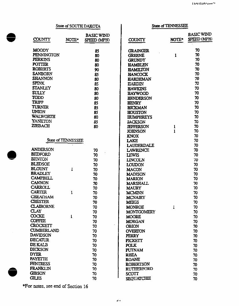
State of SOUTH DAKOTA
BASIC WIND COUNTY NOTE* sPEED(Mpm
MOODY PENNINGTON PERKINS POTIER ROBERTS SANBORN SHANNON
EtELY SUUY TODD
zizzl32 UNION WALWORIH YANK’IDN ZlEE3ACH
state of TENNESSEE
ANDERSON BEDFORD BENIDN BLEDSOE BLOUNT BRADLEY CAMPBELL CANNON CARROLL
EiiEiAM
CLAIBORNE
E& COFFEE CROCKEIT CUMBERLAND DAVIDSON DECQUR DEKALB DICKSON DYER FAYEITE FENIRIS
GIBSON
85
ii
ii 85 80
ifi 80
ii 85 85 80 85 80
70 70 70 70 70 70 70 70 70 70 70 70 70 70 70 70 70 70 70 70 70 70 70 70 70 70 70 70
BASIC WIND COUNTY NOTE* SPEEDWH)
GRUNDY HAMBLEN HAMRXON HANCOCK HARDEMAN HARDIN HAWKINS HAYWOOD HENDERSON HENRY BICEMAN HOUSTON HWPHREYS JA(xsON JEFFERSON JOBNSON KNOX
LAUDERDALE LAWRENCE
LINCOLN LOtJ’DON MACON MADISON MARJON MARSHALL MAURY MChtlNN MCNAIRY MEIGS MONROE MONTGOMERY MOORE MORGAN OBION OVEFCON PERRY PICKEIT POLK PUTNAM
ROANE ROBERTSON RUlHERFORD SCOTT SEQUATCHIE
70 70 70 70 70 70 70 70 70 70 70 70 70 70
1 70 1 70
70 70 70 70 70 70 70 70 70 70 70 70 70 70 70
1 70 70 70 70 70 70 70 70 70 70 70 70 70 70 70 70
*For notes, see end of Section 16
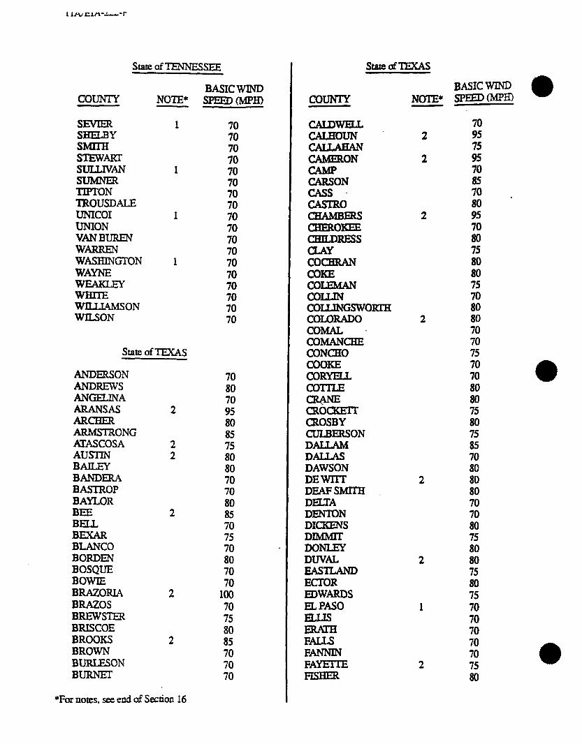
I lA/ IzlA-‘---‘r
state of TENNESSEE I
COUNTY
SSE sm STEWART SULLIVAN SUMBIER TIPTON TROUSDALE UNICOI UNION VANBUREN WARREN WASHINGTON WAYNE
SSON WILSON
NOTE*
1
state of TEXAS
ANDERSON 70 ANDREWS 80 ANGELINA 70 ARANSAS 2 95 ARCHER 80 ARMSTRONG 85 M’ASCOSA 2 75 AUSTIN 2 80 BAILEY 80 BANDER4 70 BASTROP 70 BAYLOR 80 BEE 2 85 BELL 70 BEXAR 75 BLANC’0 70 . BORDEN 80 BOSQUE 70 BOWIE 70 BRAZORIA 2 100 BRAZOS 70 BREWSTER 75 BRI!XOE 80 BROOKS 2 85 BROWN 70 BURLESON 70 BURNET 70
*For notes. see end of Section 16
BASIC WIND SpEEDoAm
70 70 70 70 70
;: 70 70 70 70 70 70 70 70 70 70 70
StateOfTEXAS
BASICWIND SPEED(MPR) NOTE* corn
i!izEF iiIzEF ZN CASS
EiEERs -0KEE CHILDRESS
EGERAN
EzzimN COLIJN COILINGSWORZIH COLORADO COMAL ’ COMANCBE CONCH0 COOKE CORYELL co-mx
z CROSBY CULBERSON DALLAM DALLAS DAWSON DEWIIT DEAFSMlTH DELTA DlENToN DICKENS DIMMIT DoNmY DW& EASTLAND ECTOR mwARDs ELPMO
EEI FMJS FANNIN FAYETTE FISHER
2
2
if
it 70 85 70 . 80 95
ii 75 80 80 75
ii 80 70 70 75 70 70 80 80 75 80 75 8s 70 80 80 80 70 70 80 75
ii 75 80 75 70 70 70 70 70 75 80
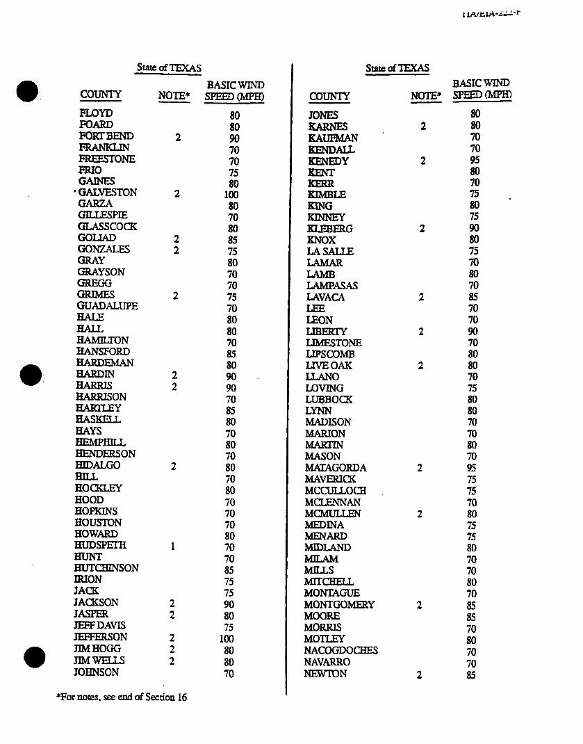
S~ofTExAS
COuNlY
FLOYD FOARD FORTBEND
FREESTONE FRIO
*EELON GARZA GILLESPIE GLAsscocK
zii%Eks GRAY GRAYSON
izzz GUADALUPE
HAMILTON HANSFORD HARDEMAN HARDIN
HARRBON
i.iEiE HAYS HEMPBILL HENDERSON HIDALGO
HOCKLEY HOOD HOPKINS HOUSTON HOWARD HUDSPEI-H
HUTCBINSON IRION JA(x JACKSON JASPER JEFFDAVIS -ON JIM HOGG JIMWELLS JOHNSON
NOTE*
2
2
2 2
2
*For notes. see end of Section 16
BASIC WIND -0
:i 90 70 70
ifi ml 80 70 80 85 75 80 70 70 75
it 80 70 85 80 90 . 90
iii 80
ii 70 80 70 80 70 70 70 80 70 70 85 75 75 90 80 75
100 80 80 70
COUNTY
JONES
KAUFMAN KENDALL KENEDY
KIMBIX KlNG
KLEBERG KNOX IASALLE
i?EF LAMFASAS LAVACA
EON LTBERIY IJMESTONE LIPSCOMB LJVEOAK LLANO LOVING LUQBOCK LYNN MADISON MARION
MASON MKAGORDA MAYERIcK MCCULLOCH MCLENNAN MCMUILEN MEDINA MENARD MIDLAm
MILLS MlTcHELL MONTAGUE MONTGOMERY MOORE MORRIS MOTEY NACOGDOCHEZ NAVARRO NEWTON
StateClflEXAS
NOTE*
2
2
2
2
BASIC WIND SEarIm
80
;: 70 95 80 70 75 . 80 75 90 80 75 70 80 70
Ei 70 90
z 80 70 75
iFi 70
ii 70 95
E 70 80 75 75 80 70 70 80 70 85 85
ii: 70 70 85

- - --- - ----I
stare OfTExAs
COUNTY
NOLAN
iiEEiEE OLDHAM ORANGE R4LoPlNTO PANOLA
iitEi!z PECOS POLK
ilEE
EEIIL REAGAN
EiTkvER
iEE0 ROBERTS ROBERTSON ROCKWAu RUNNELS RUSK SABINE
NOTE*
2
SANAUGUSTINE SAN JAQNTO 2 SANPmuao 2 SANSABA SCHLEICBER SCURRY SHAaELFORD SHELBY SHERMAN SMIIH soMERvELL STARR 2 STEPHENS sTERLlNG STONEWALL SUITON SWISHER TARRANT TAYLOR
THROCKMORTON TTIUS
*For notes. see end of Section 16
BASIC WIND =Em(MpH)
ii 85 85 95 70
;: 80
ii 85 75 70
ii 75 70
z 80 70 70 75 70 75 75 80
;: 75 80 80 70 85 70
;: 75
;o" 75 85 70 80 75 80 80 70
TOMGREEN IRAVIS
EfF
iiEi!F WALDE v.VERDE v.ZANDT VImRIA WALllEE! WALER WARD WmGKlN
tZL3N
WICHCI-A WILBARGER
XON WILSON
WOOD YaAKuM YOUNG ZAPm ZAVALA
StateOf-XEXAS
NOTE”
state of UTAH
BEAVER BOXELDER CACEIE CARBON DAGGEIT DAVIS DUCHESNE EMERY GARFIELD
IRON
iif&
MORGAN
2 2
2
2
BASIC WIND SPEmRvzpH)
ii 70 80 70
ii
$ 90 75
ii
a 90 80 80 80 95 70 75 80 70 70 80 75 75 75
70 70 70 70 75 70 70 70 70 70 75 70 70 70 70 70
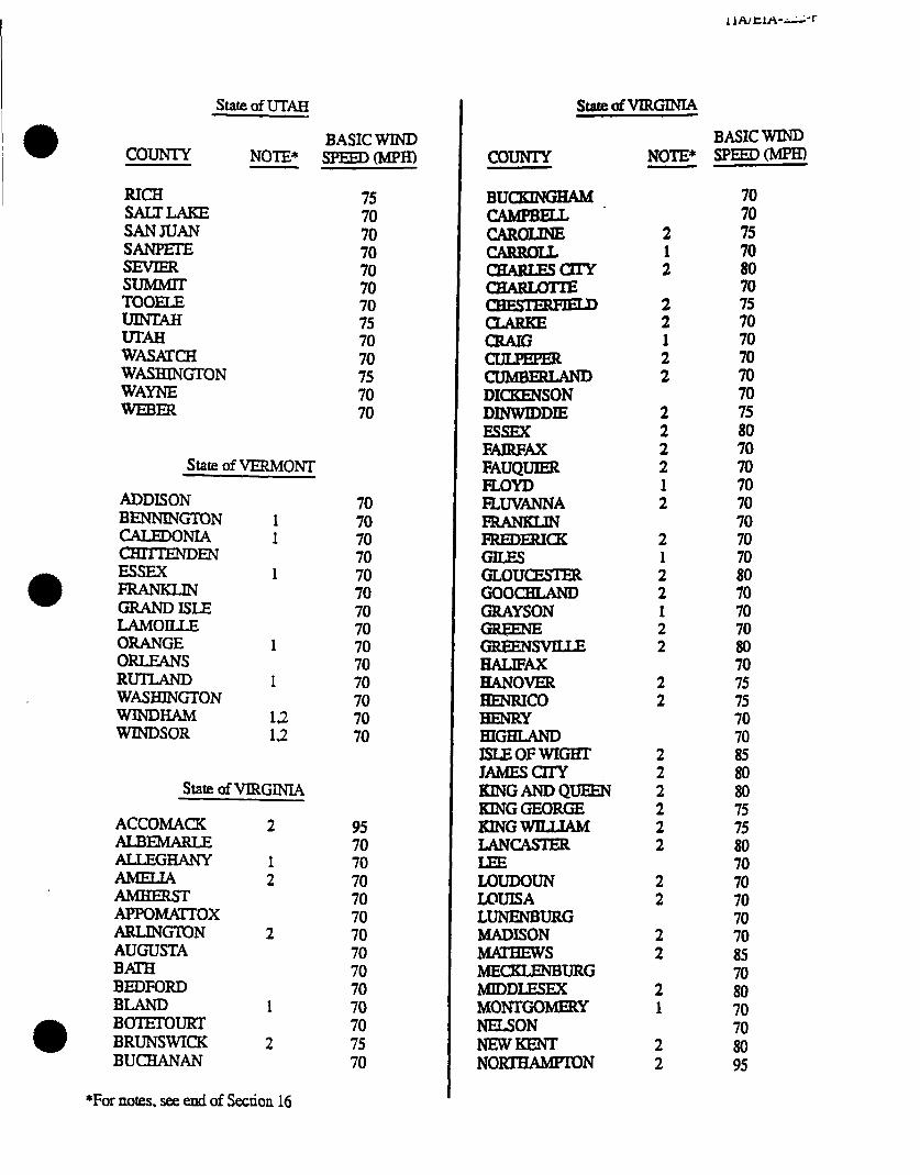
state of UTAH
BASIC WIND COUNTY sP=D(Mp)I) NOTE*
RICH SALTLAKE SANJUAN SINPETE
EErr TOOELE UINTM UTAH WASAKH WASHlNGTON WAYNE WEBER
state of VERMONT
ADDISON BENNINGIQN 1 CALEDONIA 1 -EN ESSEX 1
GIUNDISLE LAMOILLE ORANGE 1 ORLEANS RUILAND 1 WASHINGTON WINDHAM WINDSOR :2”
State of VIRGIN-IA
ACCOMACK 2 ALBEMARLE ALLEGHANY 1
2 AMIIERST APPomox ARLlNGlTlN 2 AUGUSTA B4Xl-H BEDFORD BLAND 1 BOTETOURT BRUNSWICK 2 BUCHANAN
*For notes. see end of Section 16
75 70 70 70 70 70
;i 70 70 75 70 70
70
;i 70 70 70 70 70 70 70 70 70 70 70
95 70 70 70 70 70 70 70 70 70 70 70 75 70
COUNIY NOTE*
EELER CUMBERLAND DIQUZNSON DINWIDDIE ESSEX FAIRE! FAUQUIER FLOYD EWANNA
iiiiEi%
iZEkTER GOOCHLAND GRAYSON
iiiE%AE HALIFAX HANOVER HENRICO HENRY HIGHLAND ISLEOFWIGHI’ JAMESCITY KlNGANDQUEEh KINGGEORGE KINGWILLIAM LANCASTER
EEDOUN LOUISA LUNENBURG MADISON MIWIEWS MECKLENBURG MJDDLESEX MONTGOMERY NELSON NEWKENT NO-N
2
:
i 1 2 2
2 2 2 2 1 2
2
: 2 1 2 2
:
2 2 2 2 2 2
2 2
2 2
2 1
2 2
BASIC WIND sPEEDt-h@m
70 70 75 70 80 70
z 70 70 70 70
ii
z 70 70 70
$ 80 70 70 70 80 70 75 75 70 70 85 80 80 75 75 80 70 70 70 70 70 85
2 70 70 80 95
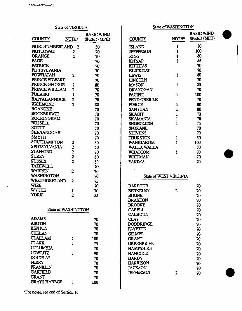
* *fi &An-----,
State of VIRGINIA
BASIC WIND COUNTY NOTE* SPEED0
NOKI’HLMBW 2 80
NOTTOWAY 2 ORANGE 2 : PAGE 70 PmCK 70 mTTsYLvANL4 PowHmAN 2 ;8 PRINCEEDWARD 70 PRINCEGEORGE 2 80 PRrNcEwILuAM 2 70 PULASKI : 70 mPPAHANNocK 70 RICHMOND 2 80 ROANaCE 70 ROCKBRIDGE 70 ROCKINGHAM 70 RUSSELL 70 SCOTr 70 SHENANDOAH 70 SMYTH 70 SO-N 2 80 SPOTSYLVANIA 2 70 STAFFORD 2 70 SURRY 2 80 SUSSEX 2 80 TAZEWELL 70 WARREN 2 70 WASHINGT’ON 70 WESTMORELAND 2 75 tz%E 1 70 70
YORK 2 85
State of WASHINGTON
ADAMS 70 ASOTIN 70 BENTON 70 Ei!ztYm 1 100 70
z&n4 1 75 70 COwLnz 1 90 DOUGLAS 70 LizELm 70
70 GARFIELD 70
70 GRAYSHARBOR 1 100
*Fur notes. see end of Section 16
State afWASHINGTON
BASIC WIND SPEEDWH) NOTE*
LINCOLN MASON OKANOGAN PACSFIC PENDOREILLE PIERCE SANJUAN SKAGII-
SNOHOMISH SPOKANE SEVENS THCJRSTON WAHKLXUM WALLAWALLA WHAKOM
1 1 1 1
1
1
1
1 1 1 1 1
1 1
1
80 100 80 85 70 70 80 70
zi 100 70 80 80 70 70 75 70 70 80
100 70 70 70 70
COUNTY
-ON KING KlTsAP KmlTAs IcLKKrrisr
State of WEST VIRGINIA
BARBOUR BERKELEY 2 BOONE BRAXTON BROOKE CABEU CALHOUN CLAY DODDRIDGE FAYEI-IE GILMER
GREENBluER HAMPSHIRE HANco(x HARDY HARRISON JACKSON JEFFERSON 2
70 70 70 70 70 70 70 70 70 70 70 70 70 70 70 70 70 70 70
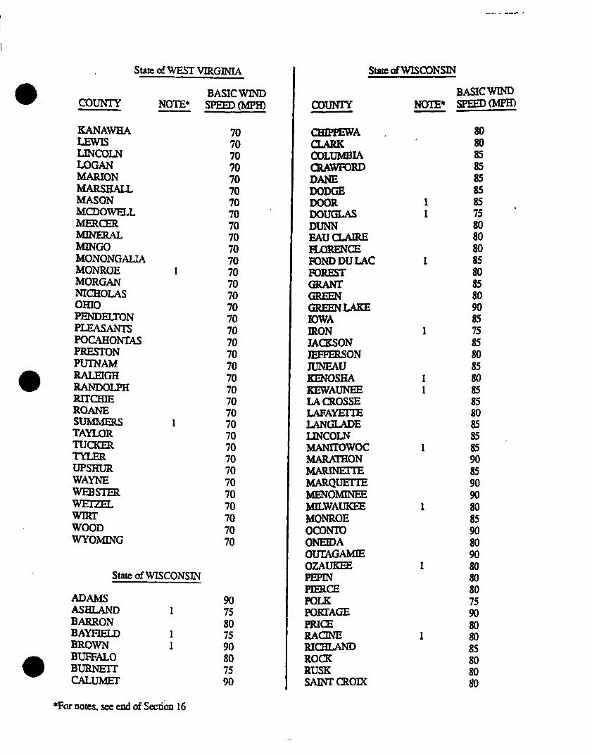
StateofwESTvIRGl.~~
BASIC WIND COUNTY NOTE* spEED(MpH)
KANAWHA
LINCOLN LOGAN WON MARSHAIL MASON MCDOWELL
ilttE?i MING0 MONONGAIA MONROE MORGAN NICHOLAS OHIO =NDEIZT’ON PLEASANTS POCAHONliU PRESTON PUINAM RALEIGH RANDOLPH RlTcHIE ROANE SUMMERS TAYLOR TucKI
UPSHUR WAYNE WEBSTER
WOOD WYOMING
70 70
;: 70 70 70 70 70 70 70 70
1 70 70 70 70 70 70 70 70 70 70 70 70 70
1 70 70 70 70 70 70 70 70 70 70 70
State of WISCONSIN
ADAMS 90 AsHrAND 1 75 BARRON 80 BAYFIELD 1 75 BROWN 1 90
4B BUFFALO BURNEIT 75 80
CALuMEr 90
State ofWIScONSIN
BASIC WIND COUNIY SPEED= NOTE*
CBIPPEWA .
COLUMBIA CRAWFO~ DANE DODGE
ERu
LF- FLORENCE PONDDULAC FOREST
iELA.IE IOWA IRON JACKSON -ON JUNEAU KENOSHA KEWAUNEE LA CROSSE LAPA- LANGLADE UNCOLN MANITowoc -ON
MARQUEITE MENOMINEE MILWAUKEE MONROE ocolvm ONEIDA OUTAGAMIE OZAUKEE
PImcE POLK PORTAGE PRICE &mNE RI- ROCK RUSK SAINT CROIX
1 1
1
1
1 1
1
1
1
1
ii 85 85 85
ii
ii
ii 85 80
ii
iz
ii 80 85 85 80 85 85
ii 85 90 90 80 85 90 80 90 So 80 80 75 90
ii: 85 80
ii
*For notes. see end of Sea&m 16
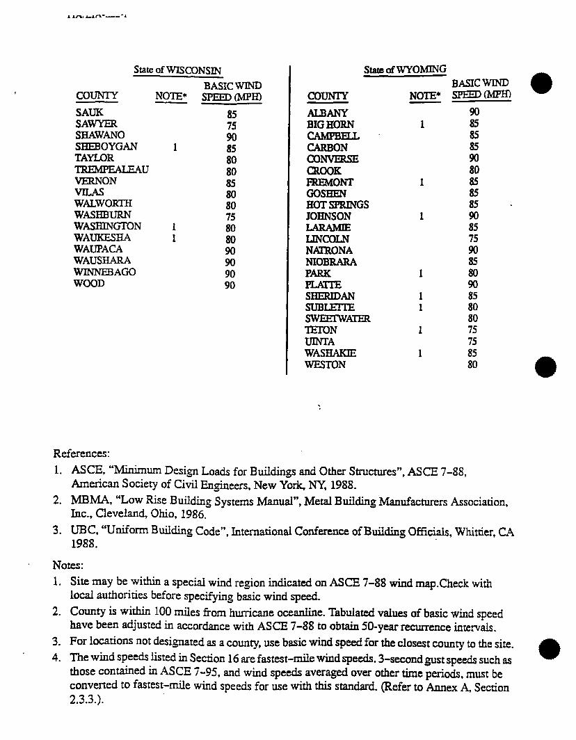
State of WISCONSIN
BASIC WIND COUNTY NOTE* spEED(Mpm
SAUK 85 SAWYER SHAWANO zl SHEBOYGAN 1 85 TAYLOR 80 TREMPEALEAU 80 VERNON 85
WLWORTH ti WASHBURN 75 WASHINGTON 1 WAUKE-SHA 1 ii WAUPACA 90 WAUSHAR4 90 WINNEBAGO 90 WOOD 90
COUNTY
StateofWYOMNG BASIC WIND
ALBANY BIG HORN CAMPBELL CARBON t3mwRsE CROOK FREMONT GOSHEN HOT SPRINGS JOHNSON
ImcoIJJ NAlRONA NIOBRARA PARK
SHERIDAN SuBLElTE SwEErwAIER TETON
iEzLKrE WESTON
NOTE*
1
1
1 1
1
1
SPEEDcMm 90
i!iE
ii 80 85 85
ii! * 85 75
E 80 90 85 80 80 75 75 85 80
.
References: 1. ASCE, ‘Minimum Design Loads for Buildings and Other Structures”, ASCE 7-88,
American society of Civil Engineers, New York, NY, 1988. 2. MBMA, “Low Rise Building Systems Manual”, Metal Building &tmfacturers Association,
Inc., Cleveland, Ohio, 1986. 3. UBC, “Unifmn Building Code”, International Conference of Building Officials, Whittier, CA
1988.
Notes: 1.
2.
3. 4.
Site may be within a special wind region indicated on AXE 7-88 wind map.Check with local authorities before specifying basic wind speed. County is within 100 miles from hurricane oceanline. Tabulated values of basic wind speed have been adjusted in accordance with AXE 7-88 to obtain 50-year recurrence intervals. For locations not designated as a county, use basic wind speed for the closest county to the site. The wind speeds listed in Section 16 are fastest-mile wind speeds. 3-secondgust speeds such as those contained in ASCE 7-95, and wind speeds averaged over other time periods, must be converted to fastest-mile wind speeds for use with this standard. (Refer to Annex A, Section 7’77)

ANNEX A: PURCHASER CHECKLIST
ElM-IA-222 standards are intemkd to set minimum uitaia for the design, fabrication and ~o~~cth of antenna supporting stnrctures. It is the responsibility of the purchaser to provide Site-specific data and requirements differing from those contained in these standards. The following checklist is intended to alert the purchaser to the most common areas where specific data may be required.
Reference Section
2.1.3 A.
B.
C.
2.3.1.2 A.
B.
C.
2.3.3 A.
B.
C.
D.
E.
F.
G.
Purchaser checklist It is the responsibility of the purchaser to verify that the wind loads and design criteria specified meet the rquirements of the local building code. If other loading criteria are required, they shall be provided to the designer.
This standard is based on an allowable stress design (ASD) method. Therefore, the use of terms with an ambiguity in meaning and intent such as survival, shall withstand, etc. is not appropriate. Dividing the calculated wind pressure by a factor is considered inconsistent with this standard. See 2.1.3.1 for the proper definition of basic wind speed.
It is the responsibility of the purchaser to specify appropriate ice loads for locations where ice accumulation is known to occur.
The standard does not specify ice-loading requirements since ice accumulation may vary subst~tially within a given geographical area.
. It is recommended that a rn,hhm l/2 in. C12.7 mm] of solid radial ice be specified for locations where ice accumulation is known to occur.
For bidding purposes it is recommended that the purchaser specify the basic wind speed (V) to obtain designs based on identical criteria. Wind speeds specified for use with the standard shall be fastest-mile wind speeds at 33 ft [lo m] above ground level.
The basic wind speed from Section 16, the equations for the exposure coefficient (Kz), and the gust response factor (cH> are based on wind conditions in open, level country, and grasslands.
The equations specified for Kz and G result in conswvative design wind loads for thm and wooded areas.
It is the responsibility of the purchaser to specify basic wind speeds and appropriate equations for Kz and @ in hurricane, mountainous, and coastal areas, in the special wind regions indicated in Section 16 and where local conditions require special consideration.
The purchaser shall identify the elevation of the base above average ground levei when the structure will be placed on another structure or on a hill or escarpment.
The purchaser shall identify the relative elevations of the guy anchors with respect to the structure base and shall identify the maximum and minimum permissible guy radii.
The basic wind speeds provided in Section 16 correspond to an annual probability of 0.02 (SO-year recurrence interval). If the purchaser requires another probability, the basic wind speed shall be provided to the designer.
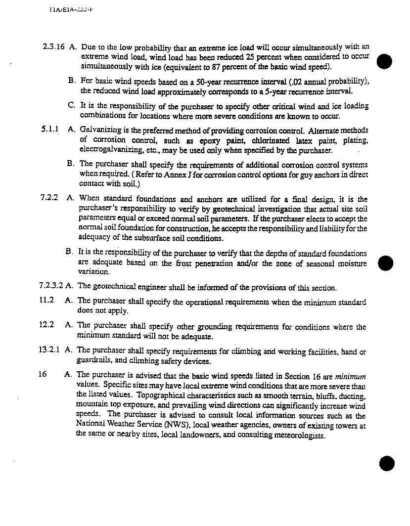
I‘IA/EIA-‘/‘-I-
2.3.16 A.
B.
C.
5.1.1 A.
B.
7.2.2 A.
B.
7.2.3.2 A.
11.2 A.
12.2 A.
13.2.1 A.
Due to the low probability that an extreme ice load will occur simultaneously with an cmeme wind load, wind load has been reduced 25 percent when considered to occur smm.baneously with ice (quivaient to 87 percent of the basic wind speed).
For b&c wind speeds based on a 50-year recurrence interval (.02 annual probabi.Q), the reduced wind load approximately corresponds to a 5-year recurrence interv~.
It is the responsibility of the purchaser to specify other critical wind and ice loading combinations for locations where mote severe conditions are known to occur.
Galvanizing is the preferred method of providing corrosion control. Alternate methods of cormion control, such BS epoxy paint, chlorinated latex paint, plating, elecuogdvanizing, etc., may be used only when specified by the purchaser.
The pudmer shall specify the requirements of additional corrosion control systems when required. ( Refer to Annex J for corrosion control options for guy anchors in direct contact with soil.)
When standard foundations and anchors are utilized for a final design, it is the purchaser’s responsibility to verify by geotechnical investigation that actual site soil parameters equal or exceed normal soil parameters. If the purchaser elects to accept the normai soil foundation for construction, he accepts the responsibility and liability for the adequacy of the subsurface soil conditions.
It is the responsibility of the purchaser to verify that the depths of standard foundations are adequate based on the frost penetration and/or the zone of seasonal moisture variation.
The geOteCh&al engineer shall be informed of the provisions of this section.
The purchaser shall specify the operational requirements when the minimum standard does not apply.
The purchaser shall specify other grounding requirements for conditions where the minimum standard will not be adequate.
The purchaser shall specify requirements for climbing and working facilities, hand or . . . _ -.
16
guardra% and climbing safety devices.
A. The purchaser is advised that the basic wind speeds listed in Section 16 are minimum values. Specific sites may have local extreme wind conditions that are more severe than the listed values. Topographical characteristics such as smooth terrain, bltis, ducting, mountain top exposure, and prevailing wind directions can significantly increase wind speeds. The purchaser is advised to consult local information sources such as the National Weather Service (NWS), local weather agencies, owners of existing towers at the same or nearby sites, local landowners, and consuking meteorologists.
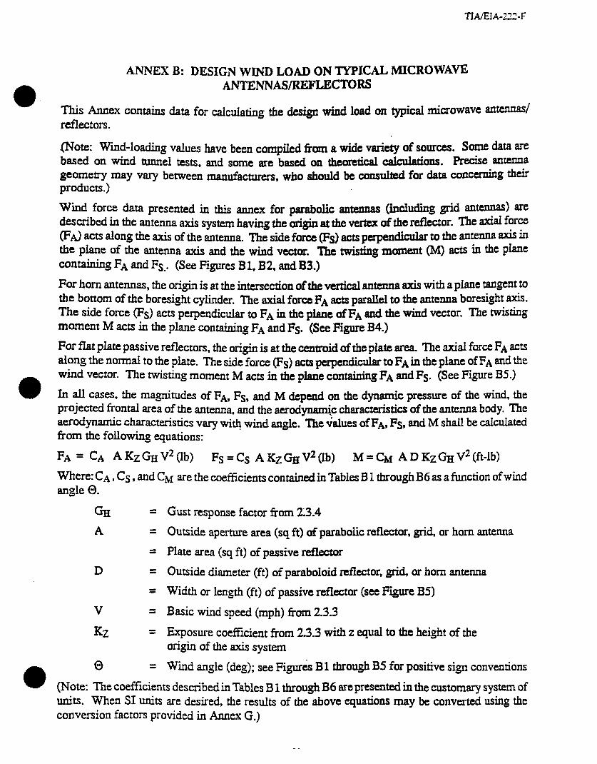
TLVEIA-222-F
ANNEX B: DESIGN WIND LOAD ON TYPICAL MICROWAVE ANT~NAS/RJ~FLECTOR~
This Annex COnkns data for calculating the design wind load on typical microwave amen& reflectors.
mote: Wind-loading values have been compiled from a wide variety of sources. Some data are based on wind tunnel tests, and some are based on theoretical calculations. Precise antenna geometry may vaty between manufacturers, who should be consulted for data concemiitg their products.)
Wmd force data presented in this annex for parabolic antennas (iucluding grid antennas) are described in the antenna axis system having the origin at the vertex of the reflector. The axial force PA.) acts along the axis of the antenna. The side force (Fs) acts perpendicular to the antenna axis in the phe of the antenna axis and the wind vector. ‘I’he twisting moment (M) acts in the plane cOn*g FA and Fs.. (See Figures B 1, B2, and B3.)
For horn antennas, the origin is at the intersection of the vertical antenna axis with a plane tangent to the bottom of the boresight cylinder. The axial force FA acts parallel to the antenna boresight axis. The side force (Fs) acts perpendicular to FA in the plane 0fF~ and the wind vector. The twisting moment M acti in the plane containing FA and Fs. (See Figure B4.)
For flat plate passive reflectors, the origin is at the cemroid of the plate area. The axial force FA acts along the normal to the plate. wind vector.
The side force (Fs) acts perpendicular to FA in the plane of FA and the The twisting moment M acts in the plane containing FA and Fs, (See Figure BS.)
In all c=es, the magnitudes of FA, Fs, and M depend on the dynamic pressure of the wind, the projected frmal area of the antenna, and the aerodynami.c characteristics of the antenna body. The aerodpdc characteristics vary with wind angle. The values of FA, Fs, and M shall be cakukted
. from the following equations:
FA = CA AKzGrrV2(lb) Fs=Cs AKzeV2(1b) M=CM ADKz%V2(ft-lb)
Where: CA, Cs , and CM are the coefficients contained in Tables B 1 through B6 as a function of wind angle 0.
Gl = A =
5
D =
=
V =
Kz =
0 =
Gust response factor from 23.4
Outside aperture area (sq ft) of parabolic reflector, grid, or horn antenna
Plate area (sq ft) of passive reflector
Outside diameter (ft) of paraboloid reflector, grid, or horn antenna
Width or length (ft) of passive reflector (see Figure B5)
Basic wind speed (mph) fkrn 2.3.3
Exposure coefficient from 2.3.3 with z equal to the height of the Origin of the axis system
Wind angle (deg); see Figures Bl through B5 for positive sign conventions
(Note: The coefficients described in Tables B 1 through B6 are presented in the customary system of units. When SI units are desired, the results of the above equations may be converted using the conversion factors provided in Annex G.)

Table BI. Wind Force Coefficients for Typical Paraboloid Without Radome
WND ANGLE Q (DEG)
0 .00397 10 .00394 20 .003% 30 JO398 40 .OO408 50 .00426 60 AI0422 70 .00350 80 .00195
.ooooo .OOOOOO -.00012 -BOO065 -JO013 -JO0097 -.00008 -.000108
.oooo2 -.000137
.00023 -.000177
.00062 -JO0223
.00117 -.000020
.00097 JO0256
90 -.00003 .00088 100 -.00103 .00098 110 -.00118 .00106 120 -.00117 .00117 130 -.00120 .00120 140 -.00147 JO114 150 -.00198 .OOlOO 160 -JO222 BOO75 170 -.00242 BOO37
180 -.00270 .ooooo 190 -.00242 -.00037 200 -.00222 -BOO75 210 -.00198 -.OOlOO 220 -.00147 -.00114 230 -.00120 -.00120 240 -.00117 -.00117 250 -.00118 -.00106 260 -.00103 -BOO98
270 -.00003 280 .00195 290 .00350 300 xl0422 310 .00426 320 AI0408 330 JO398 340 .00396 350 AI0394
-.00088 -BOO336 -.00097 -.000256 -.00117 .000020 -JO062 .000223 -BOO23 .000177 -.00002 BOO137
JO008 .000108 .00013 .000097 .00012 .000065
CA c,,
BOO336 BOO338 .000343 .000366 .000374 BOO338 JO0278 .000214 .000130
.oooooo -.000130 -.0002 14 -.000278 -AI00338 -Al00374 -AI00366 -ho343 -BOO338

Table B2. Wind Force Coefficients for Typical Paraboloid With Radome
a WIND ANGLE
0 @EG) CA
0 .00221 aoooo 10 .00220 .00038 20 .00210 JO076 30 .00195 DO105 40 .00170 SKI125 50 .00140 .OD136 60 .00107 .00128 70 .00080 .00118 80 JO058 .00112
90 AI0034 .OOlCM 100 .00008 .OOlOO 110 -.00017 JO095 120 -.00042 .00089 130 -.00075 .00082 140 -.00105 .00078 150 -.00133 .00070 160 -.oo 154 .00058 170 -.00168 .00038
180 -.00177 .ooooO 190 A.00168 -.00038 200 -.oo 154 -.00058 210 -.oo 133 -.00070 220 -.00105 -.00078 230 -.00075 -.00082 240 -.00042 40089 250 -.00017 -.OOO95 260 .00008 -.OOlOO
270 .00034 -.00104 280 .00058 -Do1 12 290 .00080 -.00118 300 AI0107 -00128 310 .00140 -JO136 320 .00170 -.00125 330 .00195 -.00105 340 .00210 :.OOO76 350 .00220 -JO038
.ooooO -.ooo204 400285 -JO0277 -.Ooo205 -.ooo114 -.OoOOo2
.m130
.000268
.000390
.000434
.ooo422
.ooo4o4
.000357 JO0232 JO0132 AIOOO63 .000022
.oooooO -.000022 -.oOOO63 -A?00132 -.000232 -JO0357 -.w -AI00422 -.000434
-.000390 -A?00268 -.000130
AKNlOo2 Am01 14 JO0205 .000277 AM0285 mO204
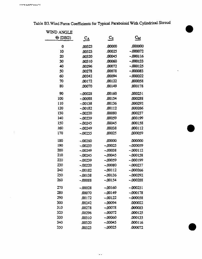
* *cad LI‘3-----,~
Table B3.Wind Force Coeffkients for Typical Paraboloid With Cyiindrical Shroud
‘WIND ANGLE
Q (DEG)
0 .00323 10 SKI323 20 JO320 30 .OO310 40 .00296 50 SKI278 60 AI0242 70 .00172 80 .00070
90 -JO028 100 -.00088 110 -At0138 120 -JO182 130 -.00220 140 -.00239 150 -.00245 160 -.00249 170 -.00255
180 -.00260 190 -Al0255 200 -Al0249 210 -XI0245 220 -.00239 230 -.00220 240 -.00182 250 -XI0138 260 -.00088
270 -AI0028 280 .00070 290 JO172 300 AI0242 310 AI0278 320 .00296 330 .003 10 340 .00320 350 MI323
.OOOOO .oooooo BOO25 -.000072 AI0045 -.000116 .ooo6o -.000133 JO072 -.000125 .00078 -.000083 .ooo94 -.oOOO22 .00122 .000058 JO149 JO0178
.00160 AI00251
.00154 Al00288 Al0136 .000292 .00112 .000266 .00080 AI00237 AI0059 .000199 JO045 .000158 .00038 .000112 40025 .000059
.OOOOO -JO025 -JO038 -.00045 -.ooo59 -JO080 -.OOl i2 -JO136 -AI0154
.oooooo -.000059 -.000112 -.000158 -.OOo 199 -JO0237 -JO0266 -.ooo292 -AI00288
-.00160 -.000251 -AI0149 -.ooO178 -.00122 -.000058 40094 moo22 -.00078 .000083 -.00072 .000125 -.00060 .000133 -.00045 XI001 16 -BOO25 .000072
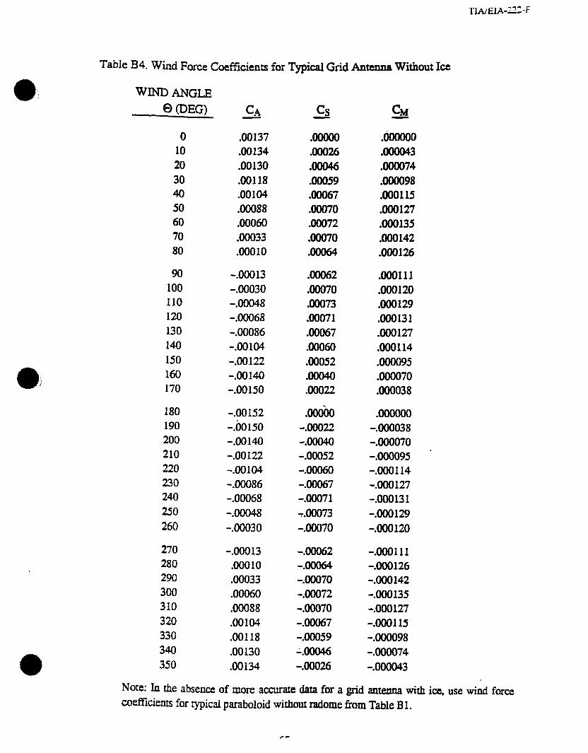
Table B4. Wi.& F orce Coefficients for Typical Grid Antenna Without Ice
WIND ANGLE 63 @EG)
0 xl0137 10 .00134 20 .00130 30 .00118 40 .OOlO4 50 Jo088 60 .00060 70 .00033 80 .OOOlO
90 -.00013 100 -.00030 110 -JO048 120 -.00068 130 -JO086 140 -.00104 150 -.00122 160 -.00140 170 -.00150
180 -.OO 152 190 -.ilolSO 200 -Ml140 210 -.oo 122 220 -Al0104 230 -JO086 240 -.00068 250 -JO048 260 -.00030
270 -JO013 280 .OOOlO 290 JO033 300 .00060 310 MO88 320 .00104 330 JO118 340 .00130 350 .00134
CA
.ooooO
.ooo26
.ooo46
.ooo59
.00067
.00070
.00072
.ooo70
.ooo64
.bOOOO
.oOOO43
.oooO74
.000098
.000115 MO127 JO0135 DO0142 .000126
JO062 .000111 .00070 .000120 .ooo73 .000129 .ooo71 .000131 .00067 .000127 .00060 .000114 Al0052 .000095 .00040 .000070 .ooo22 .000038
AMob -.ooo22 -.ooo40 -.00052 -JO060 -JO067 -.00071 &IO73 -.00070
.OOOOOO -.000038 -.000070 -.000095 . -.000114 -Al00127 -.000131 -JO0129 -.000120
-.ooO62 -.000111 -.ooo64 -.000126 -.00070 -.000142 -JO072 -AM0135 -.00070 -.000127 -Al0067 -.000115 -Al0059 -.000098 -.ooo46 -.000074 -JO026 -.000043
Note: ln the absence of more accurate data for a grid antexma with ice, use wind force coefficients for typical paraboloid without radome from Table B 1.

Table B5. Wind Force Coefficients for Typical Conical Horn Reflector Antenna
WIND ANGLE 0 (DEG)
0 .00338 10 .00355 20 JO354 30 Al0345 40 JO335 50 .00299 60 .00235 70 DO154 80 .00059
90 -.00020 .00245 .00040 100 -AI0062 .00240 BOO32 110 -.00088 .00235 .00030 120 -.00147 .00225 DO032 130 -JO225 AI0201 BOO27 140 -JO289 .00167 .00021 150 -AI0323 .00113 .00014 160 -AI0367 .00052 .00007 170 -.00375 .OOOlO .00003
180 -JO356 190 -.00375 200 -.00367 210 -.00323 220 -JO289 230 -AI0225 240 -.00147 250 -.00088 260 -BOO62
270 -.00020 -AI0245 -.00040 280 .00059 -AI0248 -.ooo46 290 JO154 -AI0237 -.ooo44 300 .00235 -.00208 -BOO35 310 JO299 -.00181 -40023 320 JO335 -.00142 -.00009 330 .00345 -.00077 .00001 340 .00354 -.ooo25 .00007 350 .00355 -.00004 .00005
cq
.ooooO
.oooo4 DO025 BOO77 .00142 .00181 .00208 .00237 JO248
aoooo -.00005 -.00007 -.OOOOl
.OoOO9
.ooo23 JO035 .ooo44 mm46
.ooooo .ooooo -.OOOlO -.00003 -JO052 -.00007 -.00113 -.00014 -.OO167 -.00021 -AI0201 -.00027 -.00225 -.00032 -.00235 -.00030 -.OO240 -.00032

Table BG.Wi.nd Force Coefficients for Typical Passive Reflector
WIND ANGLE
WDW - CA
0 JO35 1 10 .00348 20 .00341 30 .00329 40 .00309 50 .00300 60 .00282 70 AI0178 80 .0007 1
.ooooo
.00003
.00008
.OOOlO
.00013 JO018 .00021 .ooo23 .00027
.OOOOOO -.000077 -AI00134 -.000180 -AI00198 -JO0208 -.QOO262 -.ooo225 -.000129
90 -.ooo 10 100 -.00108 110 -.00235 120 -.00348 130 -JO348 140 -Al0360 150 -.00376 160 -.00390 170 -.00400
.00030 .000030 a0035 .000180 .ooo39 .000225 BOO36 ,000210 .ooo29 DO0148 40023 DO0126 a0019 .000109 .00012 .000080 .00008 .000042
180 -.00403 .OOOOO .oooooo 190 -.00400 -.00008 -.000042 200 -.00390 -.00012 -.000080 210 -.00376 -.00019 -.000109 220 -.00360 -.00023 -.OOO 126 230 -AI0348 -.ooo29 -.OOO 148 240 -.00348 -JO036 -.000210 250 -.00235 -.00039 -.bOo225 260 -.00108 -.00035 -JO0180
270 -.OOOlO 280 .0007 1 290 AI0178 300 .00282 310 .00300 320 .00309 330 Al0329 340 a034 1 350 .00348
-.00030 -.000030 -BOO27 .000129 -JO023 .000225 -JO021 JO0262 -.00018 .000208 -AI0013 .000198 -.00010 .OOO 180 7-.OOOO8 .oOO 134 -.00003 .000077
cs
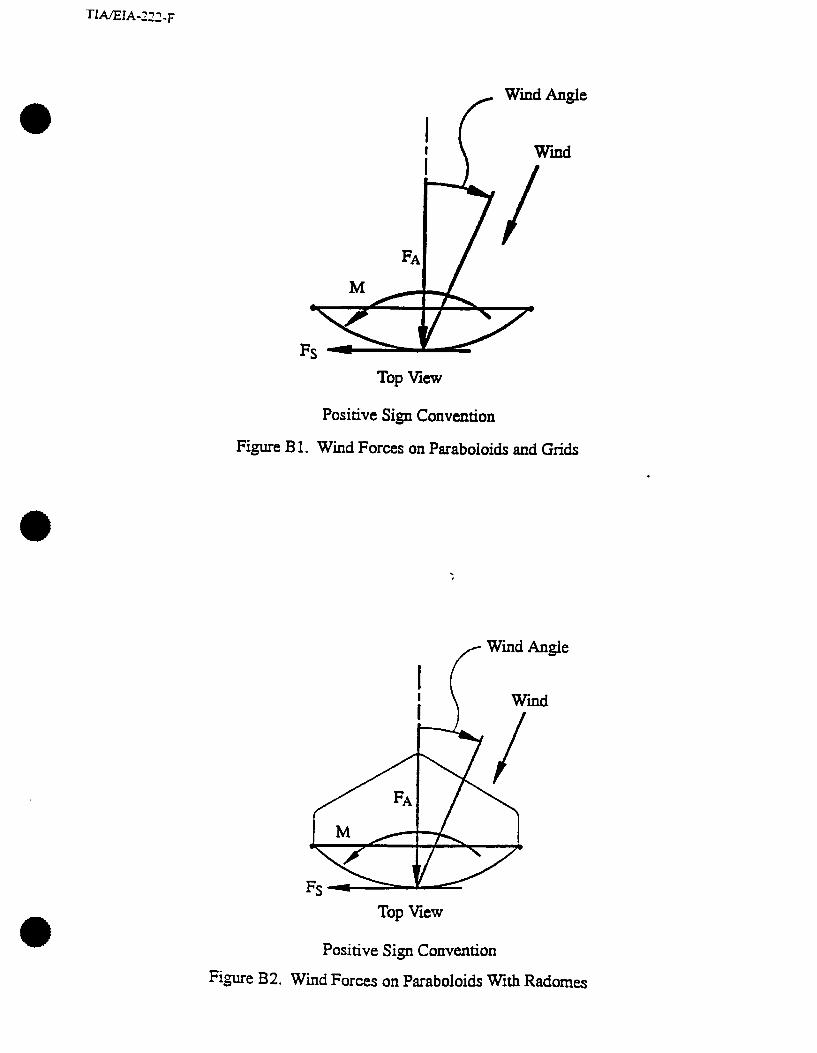
TIAEJA-222-F
r Wind Angle
Wind
Top View
Positive Sign Convention
Figure B 1. Wind Forces on Paraboloids and Grids
fl Wind Angle
Top View
Positive Sign Convention
Figure B2. Wind Forces on Paraboloids With Radomes

Top View
Positive Sign Convention
Figure B3. Wind Forces on Paraboloids With Cylindrical Shrouds
Side Elev.
.
Top View
I Fs
Wind
Angie
Figure B4. Wind Forces on Conical Horn Reflector Antennas
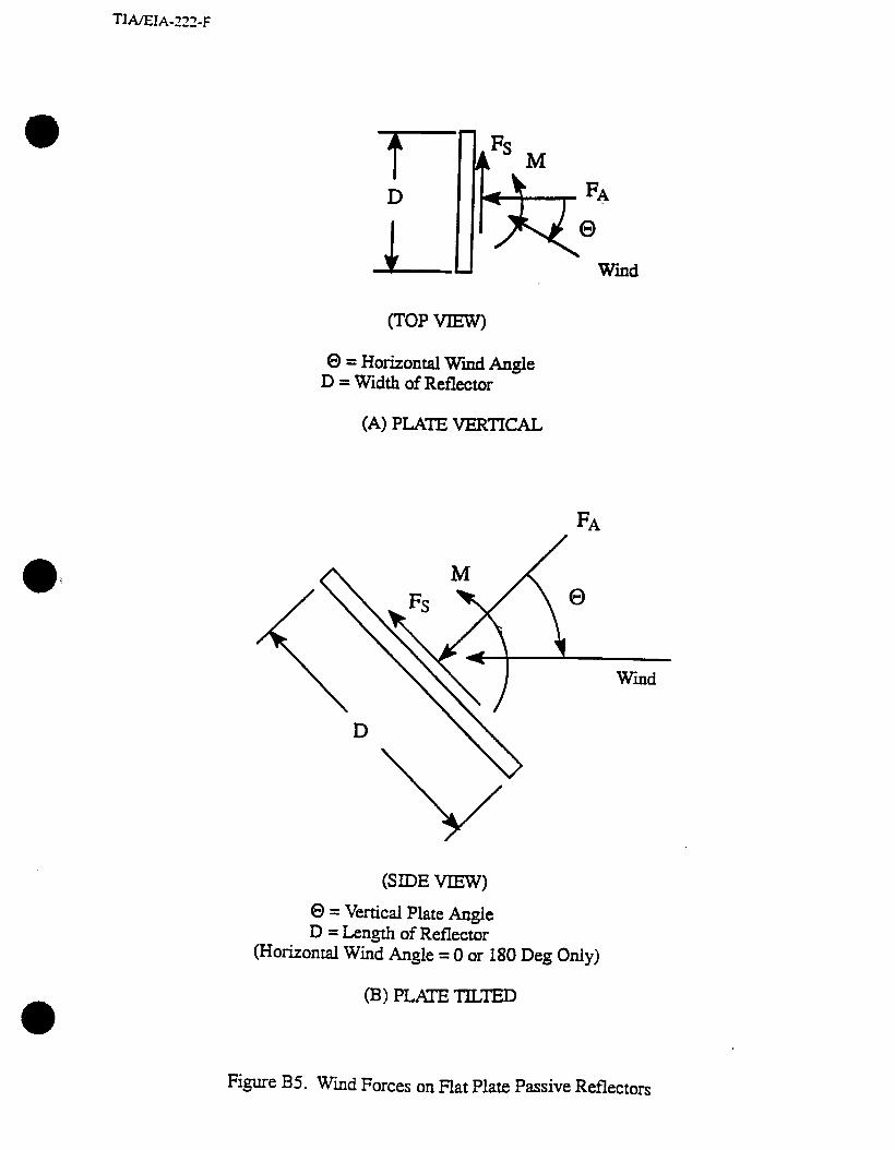
0 = Horizontal Wmd Angle D = Width of Reflector
(A) PLATE VERTICAL
(SIDE VIEW)
0 = Vertical Plate Angle D = Length of Reflector
(Horizontal Wind Angle = 0 or 180 Deg Only)
(B) PLATE TILTED
Figure B5. Wind Forces on Flat Plate Passive Reflectors
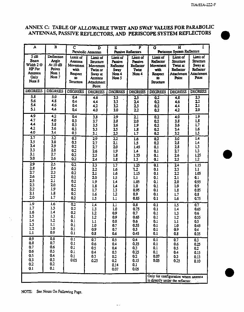
TLVEIA-222-F
ANNEX c: TABLE OF ALLOWABLE TWIST AND SWAY VALUES FOR PARABOLIC ANTENNAS, PASSIVE REFLECTORS, AND PERISCOPE SYSTEM REFLECTORS
rl)
A B C D F G H I
parabolic Asnemas Len,- Paiscope system Refkmfs
3dE DCflCZIiOfl Limitof Limit of l&lit& -of Limitof Limitof ualitof BCSII Angie Antenna SlnJcture Fhssivc h!iSiVC
WgirQ A;,” Movement Movement Ibfkcmc Reector I+iEzzt Twistat stru- kg2 with Twistof S-Y nviat -
Antenna OdY
Note 1 *ea Note7
Sway at Note4 Note4 Antenna
stn~ture Attachment Nooe 5
Rigct *Ft A!!1
Stll!LR% hint
Note 8 Felt
DJZFLEE.S DEGREES DEGREES DEGREES DEGREES DBGREBS DEGREES DEGREES DEGREES
i:: ii
4.6 4.4
i-i .
:I 0:4 0.4
i-i
4i
:J 22 iis iii ii
4.0 :5 ii E ti ti
:; i4
4.0 42 03 0.4
3.8 $78 ifi iii ii
4.0 1.9 1.8
2.6 4.2 :: i:
1.9 i:!
1.7
4.0 E
0:3 3:1 2i 1.8 ii 1.7 0.2 S:Z :;”
;4 3’:: 2
33:: 2’:; 21:; ii :4 0”; t:
1.4
0”; ::A iI
22; 20 1.45
2J 19 1.4 :: if
::;
:; 1.8 1.35 i:: tS”
i-k 2.4 1.8 1.3 1:2
2”: 25
s-i 2i
i4 ill
1.7 :f
0.1 1.15
z z
iI2 %
:-: lI5
1.15 :: 0:1
22 k 1.1 0:1
2”; 2.0 2.1 8: :-;
1.4 :::
0.1 zli 0.95 22 1.9 i..9 0.9
ii 1.7 1.8 02 8: 1:7
:4 iI: 1.8
:;6 i-F
0.85
:: ok t : 1.7 0.8 1.6 0.75
:-; 1.4 :;” 82 1.4 1.1 0.8 0.1 1.5 0.7
1:6 :: 1.0 0.75 0.1
1.5 1.3 i:: iii 8:L 8::
::‘: 0.65
12 1.4 12
iii5 X:: 1.1
1.3 :i 1.0 ii; E5 :: ::
1.2 io iI:5
1.1 0:9 0”:: iI; ii: ::5 :: iii ii5
0.9 i:;
0.1 0.7 05 iii5
0.1 i-7” ::i
0.3
i6 8;” 2
0:1 x;” ii
0:3 ii5 0”:: 8:: 82
0.5 0.4 0.15
if: E 8f5
ifi Oi5 02
ii-f5 i-i7
i-f4 0:07 0.05 0:1 0:05 & 0.13 0.10
0:1 0.1
OdY fOr c0nfiilion where anunna is dirmly under the nflecmr. ’ I
NOTE: See Notes On Following page.
TIAEIA-222~
Notes:
a 1. If whes for columns “A” and “B” are not available from the manufacturer (s) of the antenna
system or from the user of the antenna system then values &ail be obtained fkom Figure CL c2, or c3.
2. Iimh of beta-n movement for twist or sway (treated separatiy inmost anaiyses) will be the sum of the appropriate figures in CO~UIIIIS C 9; b, G & H.-and G-&z L c-ohm&G, k & L appiY to a Vertical periscope configuration.
3.
4.
5.
6.
7.
8.
It is not intended that the values in this table imply an accuracy of beam width determination or SbuCtud rigidity calculation beyond known practicable values and computational procedures. For most microwave structures it is not practid to require a calculated structural rigidity of less than 114 degree twist or sway with a 50 mi/h (22.4 III/S) Basic Wind Speed.
For passive reflectors the allowable twist and sway values are assumed to incbrde the effects of all members contributing to the rotation of the face under wind load. For passives not elevated far above ground (approximately 5 to 20 feet (1.5 to 6 m) clearance above ground) the stmcm.re and reflecting face supporting elements are considered an integral unit. Therefore, separating the structure portion of the defiection is only meaningful when passives are mounted on
conventional microwave structures.
The allowable sway for passive reflectors is considered to be 1.4 times the allowable twist to account for the,amount of rotation of the face about a horizontal axis through the face center and paraki to the face compared to the amount of beam rotation along the direction of the path as it deviates from the plane of the incident and reflected beam axis.
Linear horizontal movement of antennas and reflectors in the amount experienced for properly designed microwave antenna system support structures is not considered a problem (no significant signal degradation atttibuted to this movement).
For systems using a frequency of 450 MHz, the half power beam widths may be nearly 2 @ degrees for some antennas. However, structures designed for microwave relay systems will usud.ly have an inherent rigidity less than the chart.
maximum 5 degree deflection angle shown on the
The 3 dB beam widths, 2 0 HP in column “A” are shown for convenient reference to mamrfacmrers’ published antenna information. The minimum deflection reference for this standard is the allowable total deflection aneie Q at the 10 d.B

TIAEIA-222-F
R=w@= ‘TV or ‘Tr
(feet)
i
10.
6%.
sm.
40.
a.
20.
IS.
10.
9.8
6.8
7.0
6.8
f
s.n
- 4.0
~
3.0
2.0
1.s
2.8
6.8
6.e
10.
’ Plan or elevation of flat face dkCt0rS
- me
-- 7.8
6.0
s.e
4.0
f
1.S
+
i Flatface~m
-on lmifaml amplialde
Note: For the rotatiun. u of the naector about INS =ner. the defktion beam angie 0. may vary hm
--w e=.$& l-l
l pO2u~accordancewiththe~sys~gFameay. . Rectanguiar~squareapemrre HiHVaFetheprojected dimens~alongthebe~path
NOMOGRAPH, DEFLECTION ANGLE, 8 AT 10 dI3 POINTS FOR RIxT.GUUR
APERTLJRE (FLAT FACE REFLECTOR)
Figure Cl
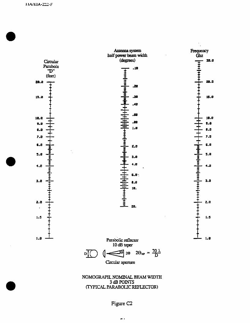
cIircu& Paraboia
(E) m.0
IS.8 --
18.8
9.8
0.0
7.0 --
6.0
s.0
4.0
3.0
2.6
.f
1.s
1.0
(degrees)
~
.10
.2a
30
-40
.m
.m
T
1.8
I 2.6
3.8
4.8 .
Parabolic nzflector 1odBtapr
Circniar apemm
NOMOGRAPH. NOMINAL BEAM WlD-lH 3dBPOINrs
(TYPICAL PARABOlXXEFLECI.OR~
6.6
v
S.8
i
4.8
3.0
2.6
1.S
1.8
Figure C2
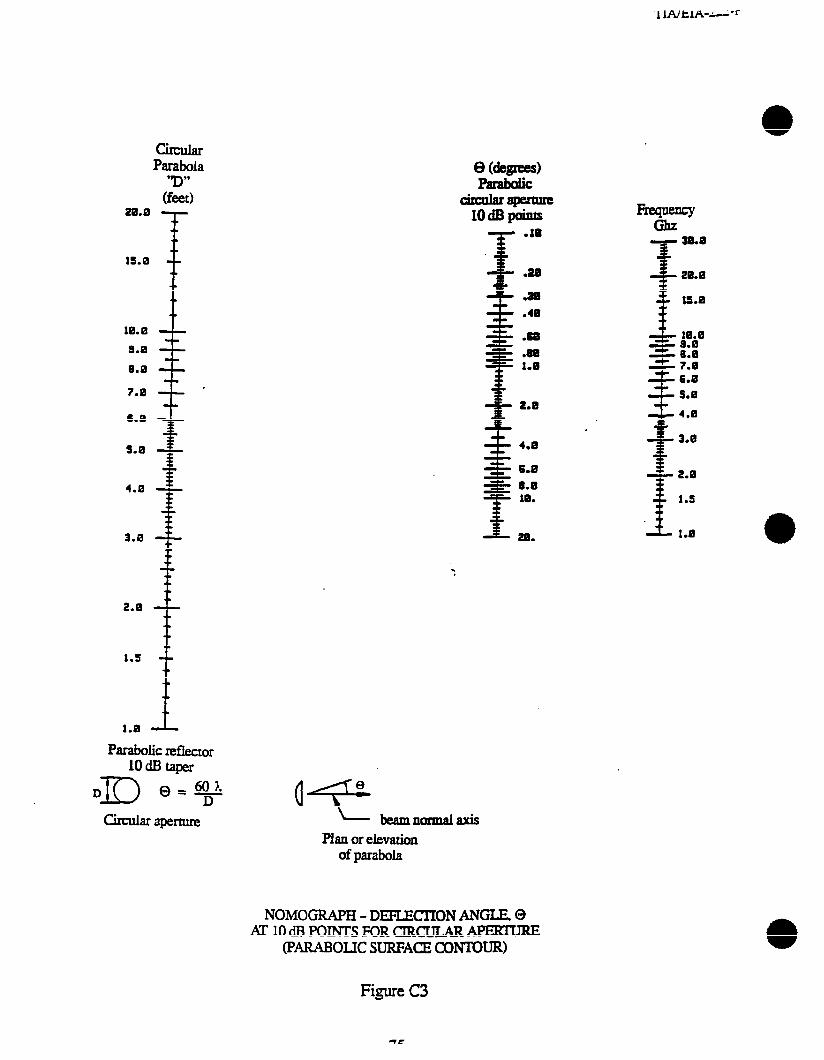
6.8
s.0 i
4.8 Q
7.8
2.0
1.s --
1.0 -
Parabolic reflecror lOdEhap
60 ?L Q’T
circular aperture
.
- beamnorm2laxis
Plan or elevation of parabola
NOMOGIUPH - DEFLECI’ION ANGIE 0 ~1OdBPOINTSFORCIRCULAR~
(PARABOLIC SURFACE coNTouR)
l+YirF
i
30.0 20.8
tS.a
& 10.8 - 9.8 - 8.0 z 7.8
s 6.0 5.8
f
4.8
v
3.0
T 2.8
* 1.5
-L 1.0
Figure C3
(LEFTBUNK lNTENTIONALLY)
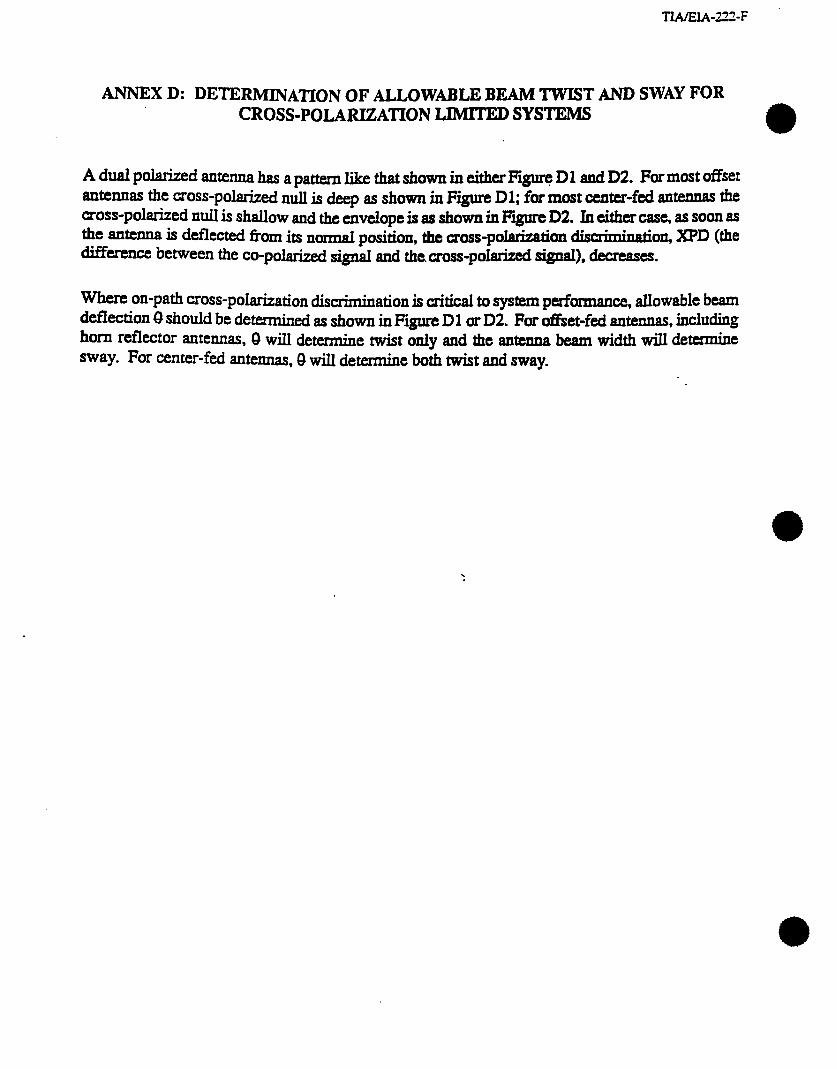
IWEIA-222-F
ANNEXD: DETERMINATIONOFALLOWABLEBEAMTWISTANDSWAY FOR CROSS-POLARIZATION LlMrrED SYSTEMS
a
A dual polarized antenna has a pa- m &at &own in either Em Dl and D2. For most offset antennas the moss-polarized null is &p as shown in Figure Dl; for most center-fed antennas the cross-polarized null is shallow and the envelope is as shown in Figure D2. In either case, as ~00x1 as the antenna is deflected fhm its normal pi&~ the cross-polarization disuiminatioa XPD (the difference bemmn the co-polarized si@ 8IIcI the. c~~~~-p~latized signal), decreases.
Where on-path cross-polarization &mation is critical to system pesformance, allowable beam ddkction 8 should be determined as shown in Figure Dl or D2. For &set-fed antennas, indUd@ horn reflector antennas, 8 will determine twist only and the antenna beam width will determine sway. For center-fed antennas, 8 will determine both tit and sway.
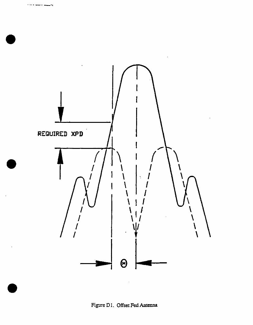
- -. . . w.. . --,
Figure D 1. Offset Fed Antenna
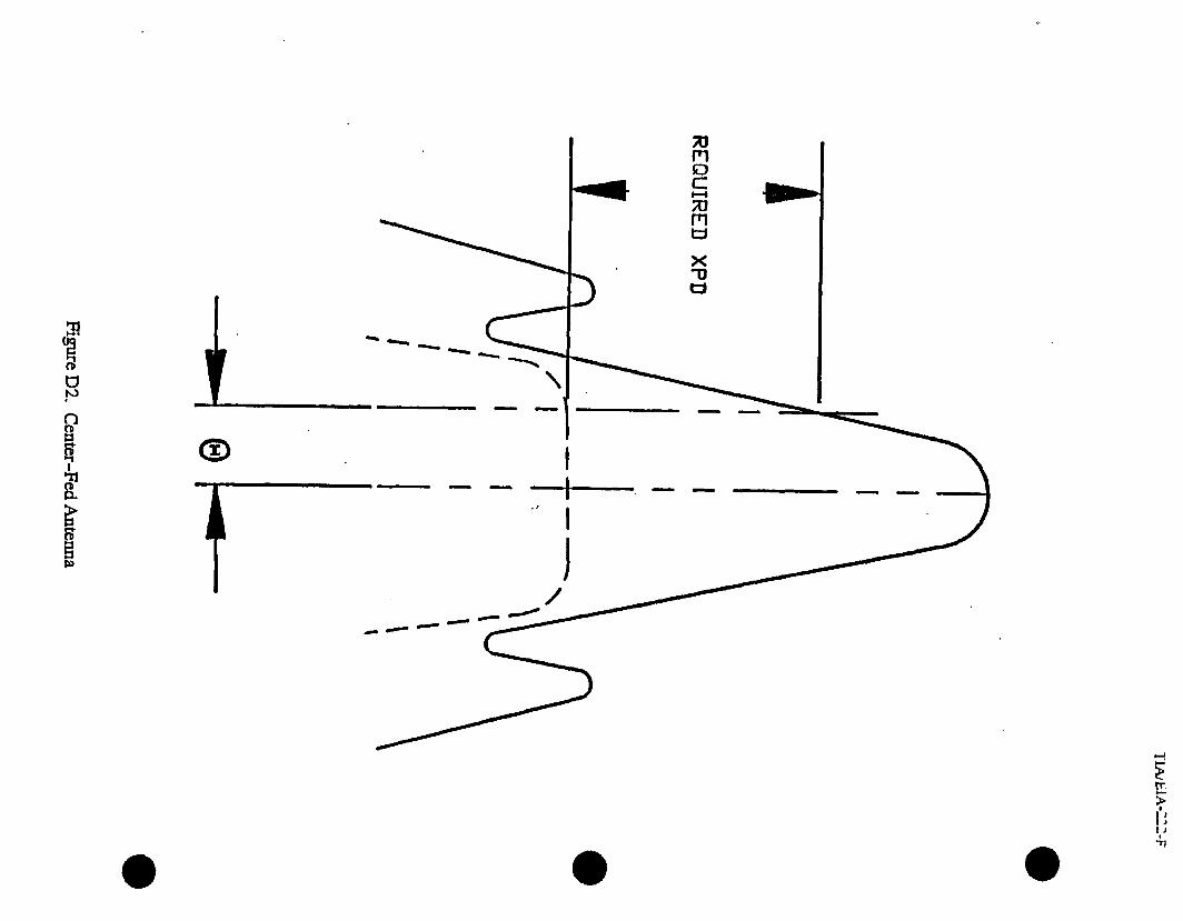
‘3 .*
0 L
t
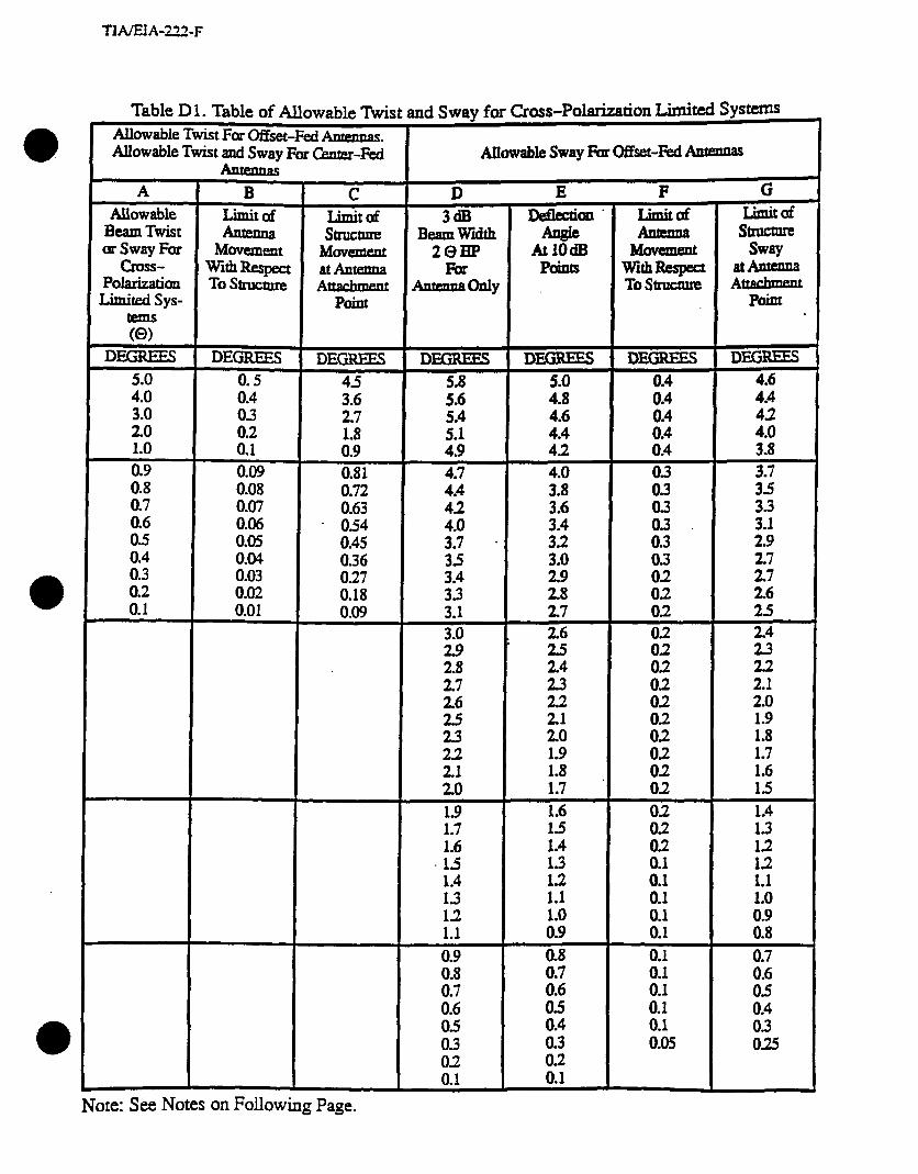
TIAEiA-222-F
Table D 1. Table of Allowable Twist and Sway for fiOSS-pO~tiOn Lhhd SYS- 4 Allowable Twist For Offset-Fed htennas. Allowable Twist and Sway For CMter-Fed
C Limitof SkUCture
Movement at Antfznna Atcachmeat
P&t
i
Allowable Sway Foa offset-&d Anmnas
D E F G
Beam Twist or Sway For
cross- Polarizatim Limited sys-
Movement with Respect To Structure
DEGREES
i-: 0:3 0.2 0.1
ii-: 607 0.06 0.05 0.04 0.03 0.02 0.01
DEGREES
32 2:7
i:: 0.81 0.72 0.63 0.54 0.45 0.36 0.27 0.18 0.09
3dB BeamWidth
2QHP Par
-MY
DEGREES 5.8 5.6 5.4 5.1 4.9 4.7 4.4 42
;; . 3’5
3% 3.1
iii 2.8 2.7 2.6 25 23
if 20 1.9 1.7 1.6 15 1.4 1.3 12 1.1 0.9
ii-; i6 05 0.3 02 0.1
z- AtlOdB
PhIUS
5.0 4.8 4.6 4.4 4.2 4.0
;::
i:;
2:
;; 2.6 25
Ei 2.2 2.1 2.0 1.9 1.8 1.7 1.6 1.5 1.4 1.3 13 1.1
ki
ii!
ii: 0.4 0.3 0.2 0.1
Limited SkllCt’Xe
Sway 2tAxlmu Attachment
Poillt
DEG= 4.6 4.4 42 4.0 3.8
3’;’
;3 2:9
;;
i=.=. 24
ii 2.1 2.0 1.9 1.8 1.7 1.6 15 1.4 13 12 12 1.1 1.0 0.9 0.8
ii2
El O> 025
Note: See Notes on Following Page.
Notes:
* 1.
2.
3.
4.
5.
6.
If values for columns “II” and ‘Y of the sway table and column “A” of the twist table are not available from the manufacturer (s) of the arnenna system or from the user of the antenna system then values shall be obtained from Figure C2, or C3.
Limits of beam movement for twist or sway (treated separately in most analyses) sre the sum of the appropriate figures in columns 9” and T” of the twist table and the sum of the appropriate figures in columns “F” and ‘%,, of the sway table.
Linear horizontal movement of antennas and refiectoxs in the amount experienced for properly designed microwave antenna system support structures is not considered a problem (no significant signal degradation attributed to this movement).
The 3 dB beam widths, 2 9 HP in cohuun “ID” are shown for convenient refmen- to manufacturers’ standard published antenna information. The minimum deflection reference for this standard is the allowable total deflection angle 0 at the 10 dB points.
The values shown in this table depict angular deflections in two orthogonal planes no& to the boresight direction: vertical elevation (sway) aud horizontal azimuth (twist). No allowance has been made for initial offsets due to mount skew, installation tolerances, paths not normal to the suppon structures, etc. Special considerations will be required in those cases.
It is not intended that the values on this table imply an accuracy of beam width determination or ~buctural rigidity calculation beyond known practicable values and computational procedures. For most microwave structures it is not practicable to require a calculated structural rigidity of less than l/4 degree twist or sway with a 50 mi/h (22.4 m/s) Basic Wind Speed.
.
1 INEIA-222-F
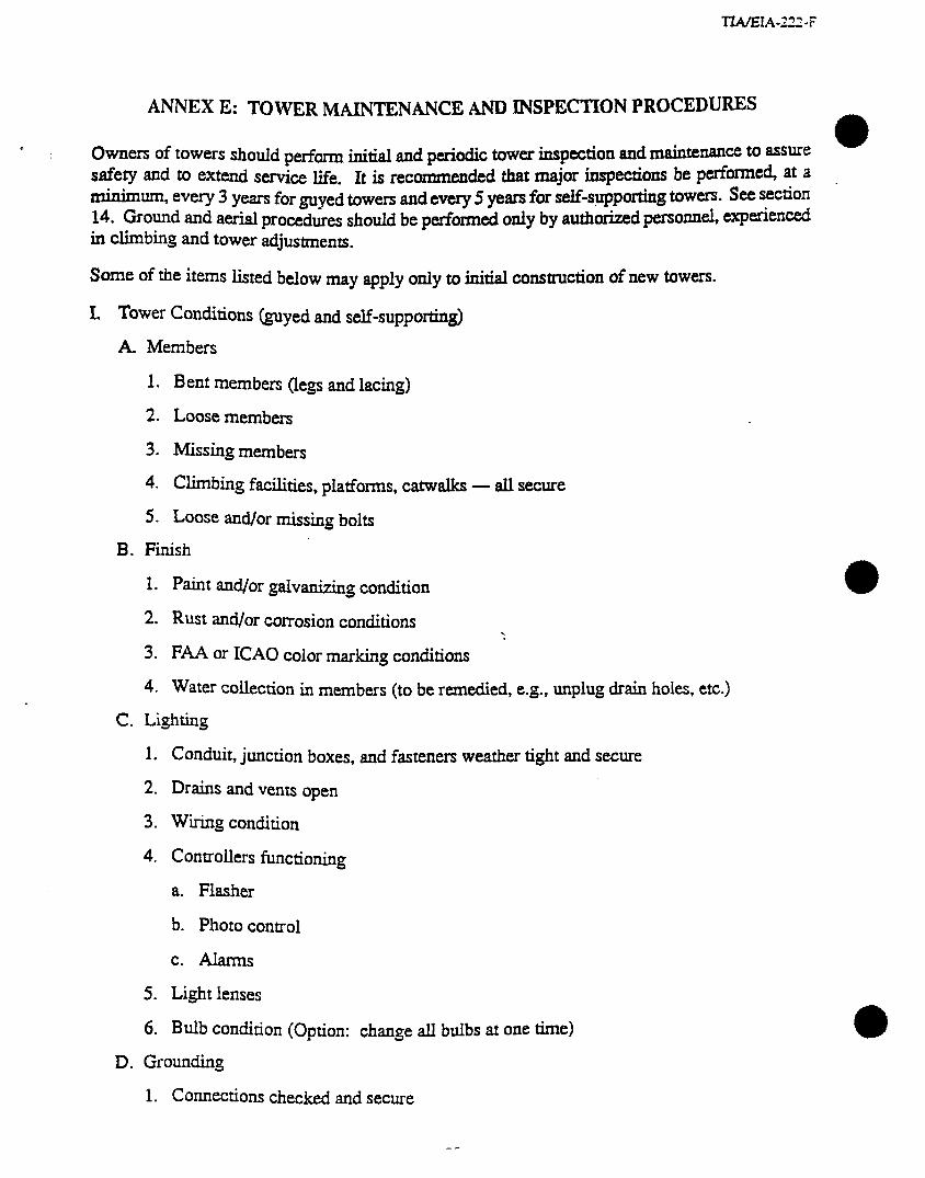
-I&V.&IA-2X-F
ANNEX E: TOWER MMJWE&MCE AND JNSPECTION PROCEDURES
&mXs Of towers shadd perform zw and p&dic tower inspection and rnaintenanCe to assure safety ami to extend s&m life. It k recommended that major inspections be performed, at a -Urn, every 3 years for myed towers and every 5 years for self-supporting tOWeS see section 14. Ground and aerial procedures shodd be p&omxxi only by authkized personnel, experienced in c&bins and tower adjustments.
SOme Ofthe items listed below may apply only to initial cmstmction of new towers.
I. Tower Conditions (guyed and self-supporting)
A. Members
1. Bent members (legs and lacing)
2. Loose members
3. Missing members
4. Chding facilities, platforms, catwalks - all secure
5. Loose and/or missing bolts
B. Finish
1. Paint and/or galvanizing condition
2. Rust and/or corrosion conditions . * 3. FAA or ICAO color marking conditions
4. Water collection in members (to be remedied, e.g., unplug drain holes, etc.1
C. Lighting
1. Conduit, junction boxes, and fasteners weather tight and secmc
2. lhins and vents open
3. Wiring Condition
4. Controllers functioning
a. Flasher
b. Photo control
c. Alams
5. Light lenses
6. Bulb condition (Option: change all bulbs at one time)
D. Grounding
1. Connections checked and secure

2. Corrosion observed and remedied
3. Lightning protection secure (as required)
E. Tower Base Foundation
1. Ground Conditions
a. Settlements or movements
b. Erosion
c. Site condition (standing water, drainage, trees, etc.1
2. Base condition
a. Nuts and lock nuts tight
b. Grout condition
3. Concrete Condition
a.
b.
C.
d.
e.
Cracking, spalling, or splitting
Chipped or broken concrete
Honeycombing
Low Spots to collect moisture
Anchor-bolt corrosion
F. Tower Assembly Profile (See Figures El and E2)
1. Antennas and feedlines (e&h)
a. Frequency
b. Elevation
c. Type
d. Size
e. Manufacturer
f. Connectors and hangers
2. Optional appurtenances (walkways, platforms. sensors, floodlights, etc.)
a. Elevation
b. Arrangement
c. Drawings or sketches
3. Foundation and anchors
a. Plan
b. Elevations (relative or true)

c. Size
d. Depths
e. Soil type (if known or necessary)
G. Tower Alignment (See Figures E3, E6, and E7)
1. ‘bmr Plumb and l’kvist (See 6.1.2.1 and 6.1.2.2)
H. Insulators (As Reqtied)
1. Insulator Condition
a. Cracking and chipping
b. Cleanliness of insulators
C. Spark gaps set properly
d. Isolation transformer condition
e. Bolts and connections secure
f. Manufacturer type and part numbers for future rephmms
II. Guyed Towers
A. Anchors
1. Settlement, movement or earth cracks
2. Backfill heaped over concrete for water shedding
3. Anchor rod condition below earth (Maintain required structural capacity of anchor during exploration, inspection and maintenance. Attachment to temporary anchorage may be required.)
4. Corrosion control measures (galvanizing, coatings, concrete encasement, cathodic protection systems, etc., refer to Annex J.)
5. Grounding (Paragraph I-D)
6. Anchor head clear of earth
B. Tower Guys (see Figures E4 and E5)
1. Strand
a. Type (1x7 EHS, 1x19 bridge strand, etc.)
b. Size
c. Breaking strength
d. Elevation
e. Condition (corrosion, breaks, nicks, kinks, etc.)
2. Guy Hardware
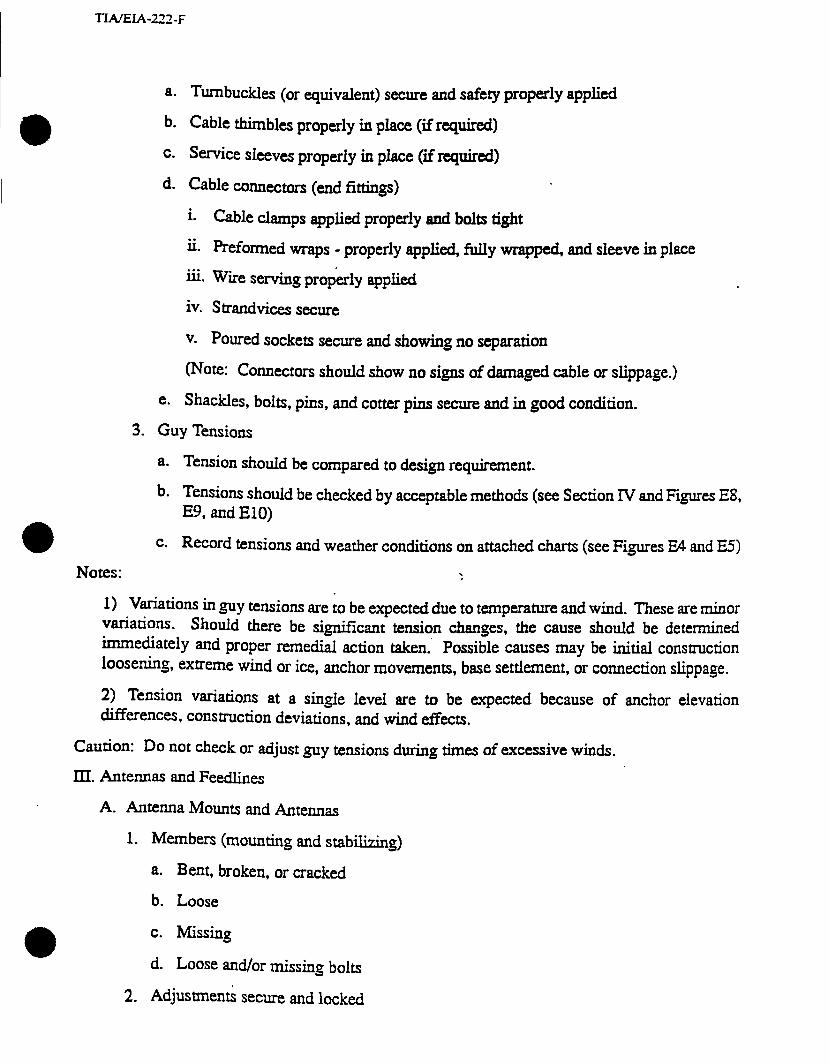
TIAEIA-222-F
a. Turnbuckles (or equivalent) secure and safety properly applied
b. Cable thimbles properly in place (if required)
c. Service sleeves properiy in place (if required)
d. Cable connectors (end fittings)
i. Cable clamps applied properly and bolts tight
ii. Preformed wraps - properly applied, fully wrapped, and sleeve in piace
iii. Wire serving proPerly applied
iv. Strandvices secure
v. Poured sockets secure and showing no separation
(Note: Connectors should show no signs of damaged cable or slippage.)
e. Shackles, bolts, pins, and cotter pins secure and in good condition.
3. Guy Tensions
a. Tension should be compared to design requirement.
b. Tensions should be checked by acceptable methods (see Section IV and Figures Eg, E9, and ElO)
Notes:
C. Record tensions and weather conditions on attached charts (see Figures E4 and a)
.
1) Variations in guy tensions are to be expected due to temperature and wind. These are minor variations. Should there be significant tension changes, the cause should be determined immediately and proper remedial action taken.’ Possible causes may be initial construction loosening, extreme wind or ice, anchor movements, base settlement, or connection slippage.
2) Tension variations at a single level are to be expected because of anchor elevation differences, construction deviations, and wind effects.
Caution: DO not check or adjust guy tensions during times of excessive winds.
III. Antennas and Feedlines
A. Antenna Mounts and Antennas
1. Members (mounting and stabilizing)
a. Bent, broken, or cracked
b. Loose
c. Missing
d. Loose and/or missing bolts
2. Adjustments secure and locked
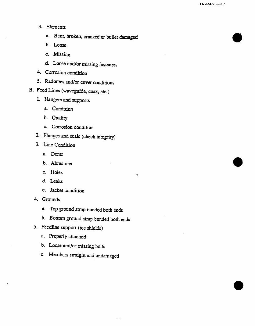
3. Elements
a. Bent, broken, cracked or bullet damaged
b. Loose
c. Missing
d. Loose and/or missing fasteners
4. Corrosion condition
5. Radomes and/or cover conditions
B. Feed Lines (waveguide, coax, etc.)
1. Hangers and supports
a. Condition
b. Quality
c. Corrosion condition
2. Flanges and seals (check integrity)
3. Line Condition
a. Dents
b. Abrasions
c. Holes
d. Leaks
e. Jacket condition
4. Grounds
a. Top ground strap bonded both ends
b. Bottom ground strap bonded both ends
5. Feedline support (ice shields)
a. Properly attached
b. Loose and/or missing bolts
c. Members straight and undamaged

TIAGIA-ZZZ-F
TOWER ELEVATION
Show the following:
- Tower Height above ground
- Location of antennas - Location of feed lines
- Location of platforms, ladders, etc.
Figure El
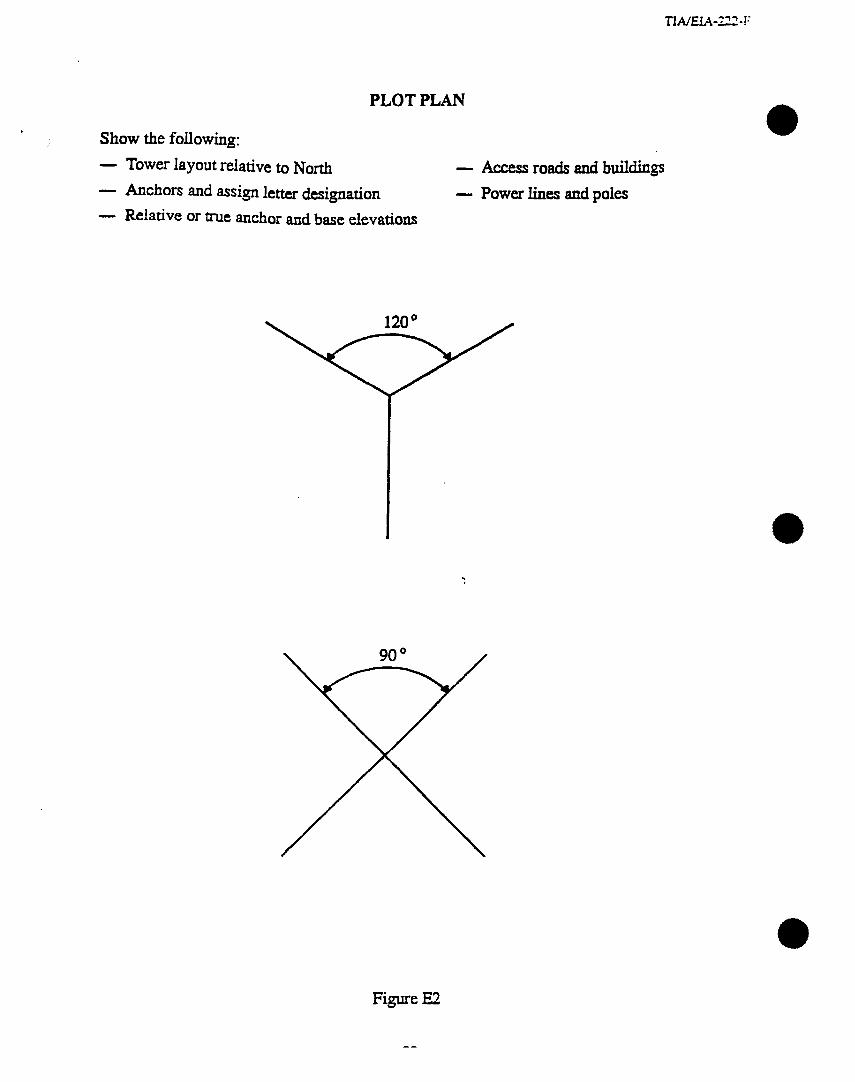
TIA/EL4-222 - 1:
PLOT PLAN
Show the following:
- Tower layout relative to North
- Anchors and assign letter designation
- Relative or tme anchor and base elevations
- Access roads and buildings
- Power lines and poles
.
Figure E2
--

TOWER LEG VERTICAL ALIGNMENT
a 1. Check with transit. %o transit setups are required Line transit paraiki to one face ad center on leg. Second setup should be at 90” on same leg. Show on sketch below the locations used for transit setup. Indicate North.
Self- Transit #l Supporting Guy Level EIevations Top to Bottom
Tower Lays Left 0 Right
Cantilever Structure
1000’ 10
900’ 9
800’ 8
700’ 7
600’ 6
500’ 5
400’ 4
300’ 3
200’ 2
100’ 1
--
--
--
--
--
--
--
--
Approximate wind speed during measurements mph
-amit #2 Tower Lays
Left 0 Right
Note: This procedure is not sufficient to determine both twist and out of plumb. See Figures E6 and E7.
Figure E3

i-
Guy Leg B
S-WAY GUYED TOWER
0
I I I
6 I I 5 I 4 I 3 I 2 I 1 I I
Guy Leg B
Figure E4
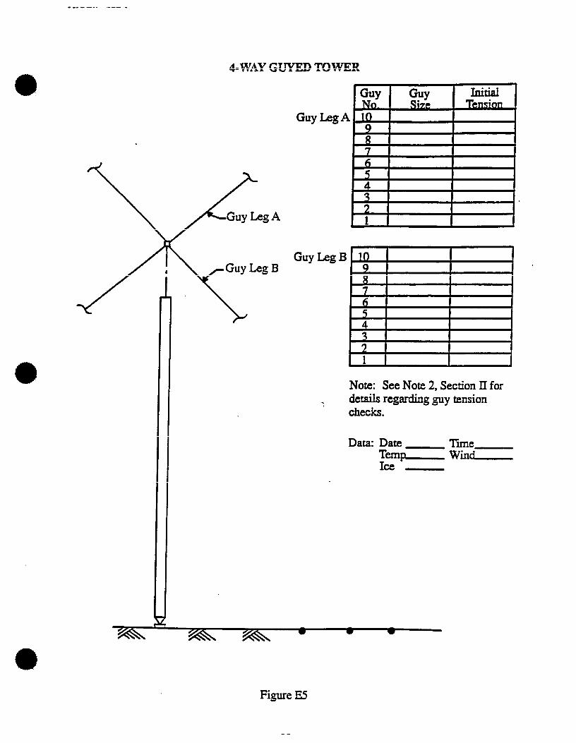
. __ ---. --- -
4-WAY GUYED TOWER
Guy Leg B
Note: See Note 2, Section II for details regarding guy tension checks.
Data: Date Time Temp- Wind- Ice -
Figure E5
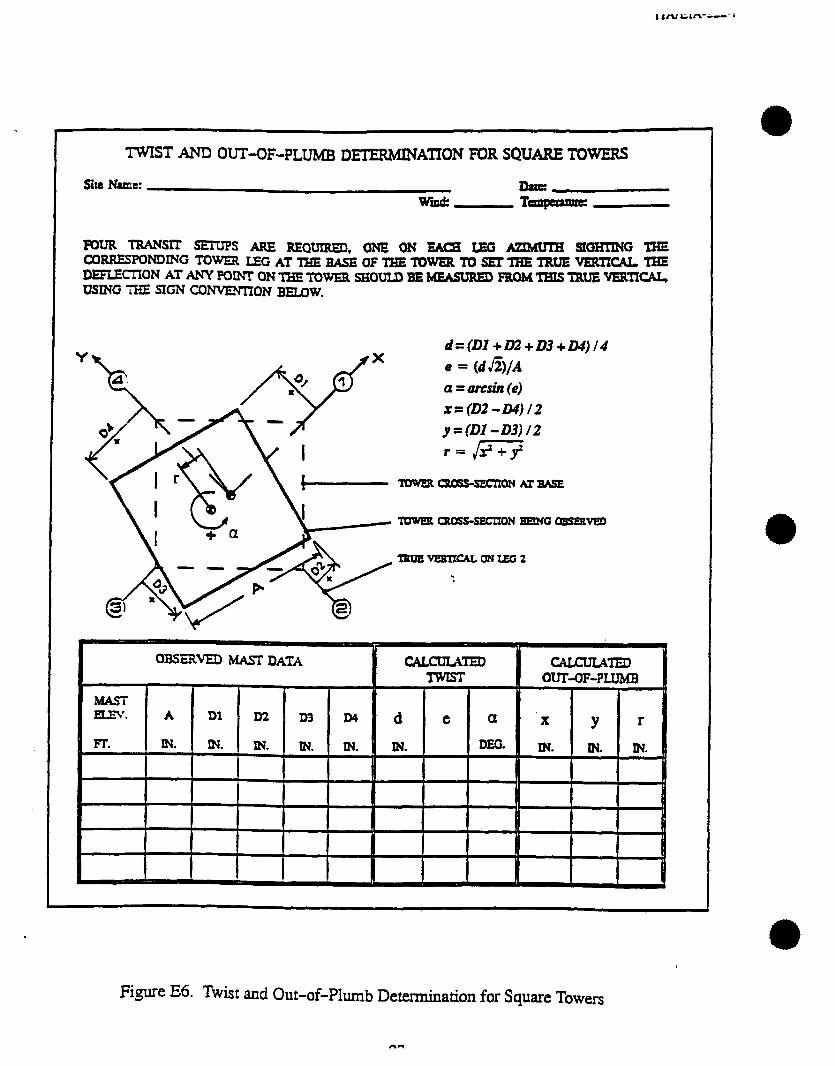
d=(Dl +D2+D3+04)/4
a = amin (e)
x=(D2-D4)/2 g=(DI -D3)/2
OBSERVED MASTDATA
I
CALmTED I
cflmJL4m OUT-OF-PLUMB I
Figure I%. Twist and Out-of-Plumb Determination for Square Towers
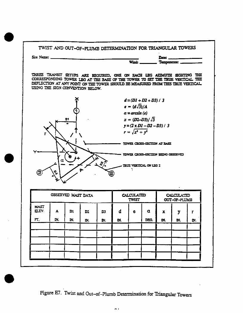
l-JIST- AND OUT-OF-PLUMB DETERMlN ATION FOR TRTANGUUJR IO-
d=(Dl+D2+03)/ 3 e = (dfi)/A a = u&n (e) I: = (D243)/fi p=(2xDl -D2-D3)/3
Figure E7. Twist and Out-of-plumb Detexminath for Triangular Towers
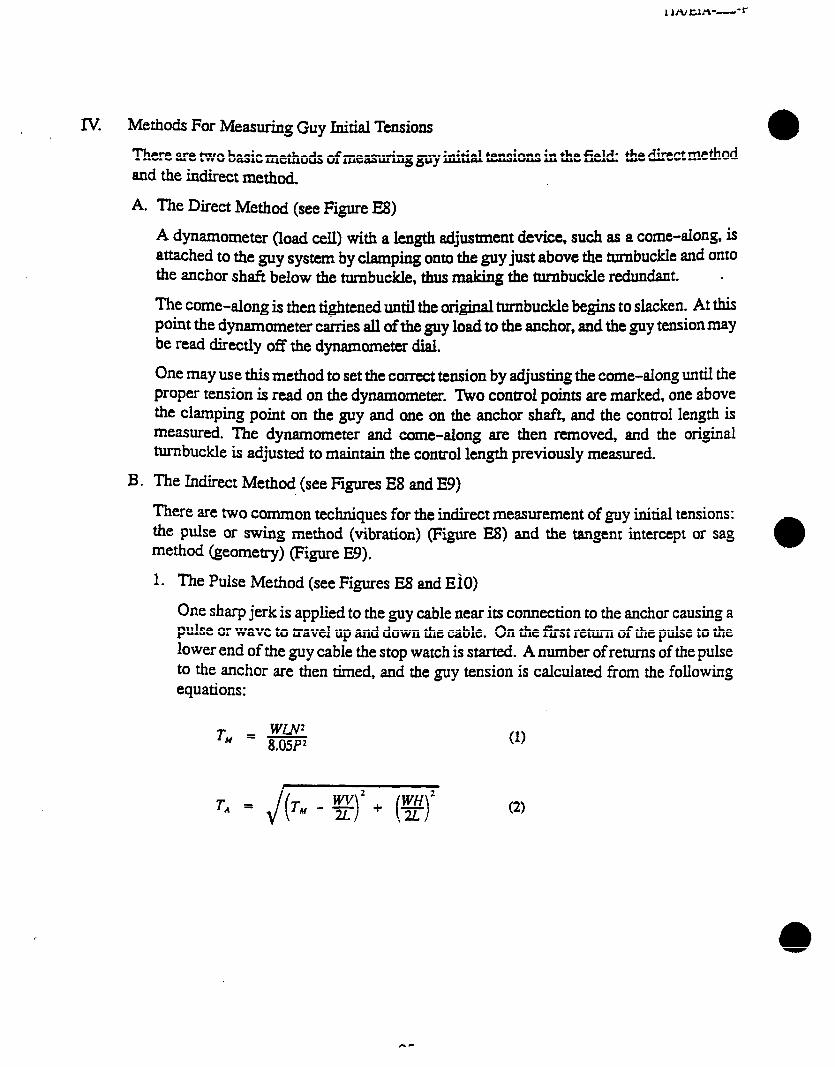
IV. Methods For Measuring Guy Initial Tensions
There are two basic methods of measuring guy initial tensions in the field: the direct method and the indirect method.
A. The Dimt Method (see Figure E8)
A dynamometer (load cell) with a length adjustment device, such as a come-along is attached to the guy system by &mpmg onto the guy just above the turnbuckle and onto the anchor shaft below the turnbuckle, thus making the turnbuckle redundant. .
The come-along is then tightened until the original turnbuckle begins to slacken. At this point the dynamometer carries all of the guy load to the anchor, and the guy tension may
be read directly off the dynamometer dial.
One may use this method to set the correct tension by adjusting the come-along tumJ the proper tension is read on the dynamometer. lI,vo control points are marked, one above the clamping point on the guy and one on the anchor shaft, and the control length is measured. The dynamometer and come-along are then removed, and the original tu.rnbuckle is adjusted to maintain the control length previously measured.
B. The Mhxt Method (see Figures ES and E9)
There are two Common techniques for the indirect measurement of guy initial tensions: the pulse or swing method (vibration) (Figure E8) and the tangent intercept or sag method (geometry) (Figure E9).
1. The Pulse Method (see Figures E8 and EiO)
One sharp jerk is applied to the guy cable near its connection to the anchor causing a pdse or wave to travel up and down the cable. On the fust return of the pulse to the lower end of the guy cable the stop watch is started. A number of returns of the pulse to the anchor are then timed, and the guy tension is calculated from the following equations:
TM = YLE 8.05P2 (1)
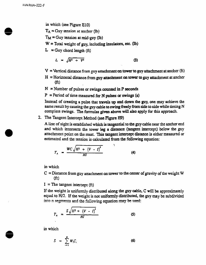
1 lAWA-222-F
2.
in which (see Figure El@
TA = Guy tension at anchor (lb)
TM = Guy tension at mid-guy (lb)
W = Total weight of guy, including ins-, etc. (lb)
L = Guy chord length (ft)
L=jrn 8)
V = Vertical distance from guy attachment on tower to guy attachment at anchor (fi) H = Horizontal distance from guy attachment cm tower to guy attachment at anchor
(ft> N = Number of pulses or swings counted in P secd~
P = Period of time measured for N pulses or swings (s)
Instead of creating a p&e that travels up and down the guy, one may achieve the same result by causing the guy cable to swing freely fkom side to side while timing N complete swings. The formulas given above wilI aiso apply fix this approach.
The Tangent Intercept Method (see Figure E9) A line of sight ik established which is tangential to the guy cable near the anchor end and which intersects the tower leg a distance (tangent intercept) below the guy attachment point on the mast. Th& tangent intercept distance is either measured or estimated and the tension is &cu.&d kom the following equation:
.
TA = WCJiiTyiq ’
HI (4)
in which C = Distance from guy attachment on tower to the center of gravity of the weight W
et> I = The tangent intercept (ft) If the weight is uniformly distributed along the guy cable, C will be approximately equal to H/2. If the weight is not uniformly distributed, the guy may be subdivided into n segments and the following equation may be used:
TA = SJm
HI 0
in which
N S = c WC, (6)

. -
Wi = Weight of segment i (lb)
Ci = lkaXe from the guy attachment on the tower to the center of gravity Of segment i (ft)
If the intercept & dlfficdt to establish, one may use the guy slope at the =&or end with the following equation:
TA = WCJl (v - Hm a)
in which
01 = Guy angle at the anchor (see Figure E9)
Note that
I = v - Htan a
m
(8)
and that
ami that WC in equation (7) my be replked with S, as was done in equation (5).

DYNAMOMETER
COME-ALONG TURNRUCKLE
PULSE METHOD
PULSE TRAVELS UP AND DOWN THE GUY N TIMES IN P SECONDS. 0
0
DYNAMOMETER METHOD
AS COME-ALONG IS TIGHTENED DYNAMOMETER CARRIES FULL LOAD WHEN TURNBUCKLE IS FULLY SLACKENED (NUTS BREAK FREE). ,
SWING METHOD
GUY SWlhS FROM a TO b AND BACK N TIMES IN P SECONDS
Figure E8. Methods of Measuring Tnitial Tension

C
t-i
t
I
Figure E9. Tangent Intercept Method
nn
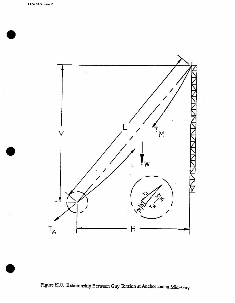
.
V /
‘ / ‘T / M
Figure ElO. Relationship Between Guy Tension at Anchor and at Mid-Guy

ANNEX F: CRITERIA FOR THE ANALYSIS OF EXISTING STRIJC-~URES
Periodic revisions to this standard a made by t&e Commitkz based upon comments received from a
the industry.
The committee does not intend that tit&g structures be analyzed for each revision of the standard; however, structural maiysis of existing structures should be performed by qualified profes~on~ engineers using the latest edition of this standard when:
a) l”h=e is a change in antennas, transmission lines, and/or app urtenances (quantity, size, location, fx type)
b) There k a change in operational re.qui.rements (tit and sway)
c) There is a need to increase wind or ice loading
To perform the analysis, the following data is rquired:
a) Member sizes, dimensions, and connections
b) Material properties
c) Existing and proposed loading; antennas (size, elevation, and azimuth), transmission lines, and appurtenances
Data may be obtained from the following sources:
a) Previous stress and rigidity ~IU$& (structure and foundation)
b) Stn~tural and detail drawings (design and as-built) ’
c) Specifications
d) Construction records
e) Field investigation
(LEFTBLANK INTENTIONALLY)
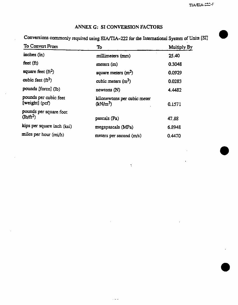
TWEiA-222-F
ANNEX G: SI CONVERSION FACTORS
COnV~iO~ CO~Ody required using EIA/EA-222 for the Intemational System of Units [Sri m
To Convert From To Multiply By
inches (in) millimeters (mm) 25.40
feet (ft) meters (m) 0.3048
square feet (ft2) square meters (m2) 0.0929
cubic feet (ft3) cubic meters (m3) 0.0283
pounds [force] (lb) newtons (N) 4.4482
pounds per cubic feet rw~gw (pa pounds per square foot Wfi2)
kips per square inch (ksi)
miles per hour (mi/h)
kilonewtons per cubic meter Wh3>
P=& (Pa)
megapascals @lIPa)
meters per second (m/s)
0.1571
47.88
6.8948
0.4470
------- -.
(LEFTBLANK INTENTIONALLY)
ANNEXH: COMMENTARYON ICEDESIGN CRITERIAFORCOMMUNKATION STRUCTURES a
1 INTRODUCTION
The meteorological phenomenon of ice accumulation is very difficult t0 predict with certainty. For tower and pole structures, ice accumulation can be one of the predominant applied loads.
The first task in developing ice design criteria is to determine if the proposed or existing site is susceptible to icing. If the site has a history of ice accumulation, the fiquency, thickness, type ad duration of icing must be determined Potential sources of this Mxmation inch& the National Weather Service (NWS), local weather agencies, owners of existing towers at the same site or nearby sites, local landowners, and consulting meteorologists.
Judgment must be exercised to detexmine if reported icing events are frequent-or rare ommnces. Likewise, in some geographical areaa, seasonal high winds and icing OCCUT simultaneously: For these situations, simultaneous application of maximum wind and ice loadings may be required.
The effect of icing on a tower generally relates directly to the type and size of tower and to the we and thickness of icing. For example, a l/Z-inch radial ice accumulation will have more impact on a short tower with small members than a tall tower with larger members. Very dl tmers may experience large thicknesses of in-cloud icing over portions of the mast. Solki or clear glaze ice has a higher density than that of rime ice or hoarfrost. Consequently, the effects of increased dead *eight from ice accumulation will vary depending on the type of ice. Large accumulations of rad.iaI ice can dramaticaIIy increase the projected wind area of tower members and antennas.

2 TYPES OF ICING (1) (2) 0)
There are several types of i&g which can accumuiate 011 COm.Ulum ‘&on sQwZUlZS. It iS important to understand where and how they form.
2.1 Hoarfrost
Hoarfrost is a fluffy 0~ feathery deposit of interkking ice crptd formed on objects, usua~y those of d diameter fialy exposed to the air, such as tree branches, wires, etc. ‘I&e deposition of hoarfrost is similar to the process by which dew is formed, except that the temperature af the &osted object must be btiow freezing. It forms when air, with a dew point below kezing, is brought to saturation by cooling. Hoarfrost has densities less than 19 lb@ [3 kNjm3].
2.2 RimeIce
Rime ice is a white or m.i,ky pm& deposit of ice formed by the rapid freezing of supercooied water drops as they impinge upon an exposed object. It is denser and harder than hoarfrost, but lighter, softer, and less transparent than glaze. Rime is composed essentially of discrete ice granules and has densities ranging from 56 w 19 WfG 19 to 3 kNjm3].
Rime is often described as soft or hard. Soft rime is a white, opaque coating of fine rime deposited especially on points and eilgcs of objects. supercooled fog.
It is usually fmed in On the windward side, soft rime may grow to very thick layer%
long feathery cones, or needles pointing into the wind and having a structure S&.&U to hoarfrost.
Hard rime is an opaque, granti maas ofi rime fanned by a dense supercooled fog. Hard rime is compact and amorphous and may build out into the wind as glazed cones or feathers. The icing of ships and shortit structures by supercooled spray usually has the characteristics of hard rime.
2.3 Glaze Ice
Glaze ice is a coating of ia, generally clear ‘aud smooth, but usually containing some air pockets. It is formed on exposed objects by the fretzing of a film of supercooled water, usually deposited by rain or drizzle. Glaze is denser, harder, and more transparent than either rime or hoarfrost. Its density may be as high as561b/ft3 C9 kN/m3].
* (1) Atmospheric Icing on S-s. Boyd & Williams. (2) Draft Guidelines for Transmissim Line Sati Ldhp. AXE (3) TaaeJman. P.. and Gring ~rten. LL. “Estimated Glaze Ice and Wrnd Loads at &e ws ~R&x for the
CQIX@OUS United States”. Air Force &bridge ~esearcfr m. B4fo1& Massachusetts. 1973.
____--- - --
3 CONDITIONS OF ICE FORMATION
‘be me of ice formed is determined by combinations of air temperature, wind speed, &oP size, and liquid water content or rainfall intensity. The icing problem, therefore, can be &Gfkd either by the meteoroIog&I conditions that produce the formation of ice or by the type of ice that is formed
3.1 Precipitation Icing
This is the most Common icing me&n&m and can occur in any area subject to freezing rain or drizzle. The ice is formed when warm, moist air is forced Over a sub-freezing, denser layer of air at the ground surface. As the watm air rises and condenses, rain falls through the coider air and freezes on objects near the ground. This frozen deposit is a clear glaze type of ice. Since this kind of weather is caused by frontal activity, it usually doesn’t last more than a day or two.
Because it is necessary for excess water to be present for glaze to form on exposed surfaces, often the excess water may freeze into icicles or other distended shapes. In actd practice, glaze ice can be seen to form on cables and guys in a variety of shapes ranging from the classical smooth cyhndxical sheath, through crescents on the windward side and icicles hanging on the underside to large irregular protuberances spaced along the cable. In most cases, glaze ice develops on st.nmms as a fairly smooth layer on tie windward surfaces with icicles forming below horizontal members. The shape of the glaze is apparently dependent on a combination of factors, such as wind speed, variations in wind speed, the angle of the wind, the turbulence of the flow, variations in air temperature and duration of the Storm. Since most of these factors vary @om storm to storm, and even during the storm a @i.ndticai shape of equivalent weight is assumed for design purposes.
3.2 In-Cloud Icing
This type of icing condition is caused by the impingement of super-cooled water dropiets of a cloud on the structure or cable. This is rime ice. It can occur in mountainous areas where ciouds exist above the freezing level or in a super-cooled fog at lower elevations produced by a stable air mass with a strong temperature inversion. These conditions can last for days or weeks.
The total amount of in-cloud ice deposited is dependent on wind speed. Since wind speed increases with height above ground, larger amounts of ice will occur towards the top of taller towers and on the cables that support or are mounted on taller towers.

.

ANNEX I: GEOTECHNICAL IWESTIGATIONS FOR TOWERS
A ~0i.i investigation by a geotecfinical @n&g firm is recommended for each tower site to determine its unique soil and physical &ract&&cs, and to provide data to develop safe design p==eters, economical foundation &maths, ami installation procedures. To ensure that the EPOn furnishes useful information to the foundation designer, the ‘geotechnical firm should be provided with the following information:
a. A plot plan and site location map with tower, equipment building and other site improvements located.
b. Tower base vertical reaction and shear and anchor vertical and horizontal reactions for guyed towers; or i’rhkrn~m compression and tension (uplift) reactions with shear for self-supporting towers.
C. Any special conditions or requirements of the specifications.
d. The minimum depth of borings for guyed tower bases should be 15-20 ft; for guyed tower anchors lo- 15 ft; for self-supporting towers, boring depth will vary depending upon the type of foundation being considered. The magnitude of the structure reactions, site and sod COndiuons may require altering the boring depth requirements.
The geotechnical report should provide the following information at minimum:
a. Boxing logs.
1. Date, sampling methods, and number and type of samples. .
2. Description of the soil strata according to the Uxkied Soil Classification System.
3. Depths at which strata changes occur referenced to a site datum.
4. Standard Penetration Test blow counts.
5. Soil densities.
6. Elevation of free water encountered and its level after 24 hours, and recommended ground water elevation to be considered for design.
7. Maximum and average depth of frost penetration.
b. Other soil characteristics or properties which may be required because of local conditions. (Refer to Annex J for corrosion control options for guy anchors in direct contact with soil.)
c. A description of alternative foundation methods with recommendations for ultimate values for passive pressure, bearing pressure and shin friction, the angle of internal friction and other appiicable soil properties and appropriate safety factors.
lin
ANNEX J: CORROSION CONTROL OPTIONS FOR GUY ANCHORS IN DIRECT CONTACT WITH SOIL
1 INTRODUCTTON WY gUY mChOfi in direct contact with soil, designed in accordance with ETA/IIA Standards, have performed We.ii without detrimental corrosion. However, depending on the required design life of the stmture and on site-specific conditions, corrosion control measures, in addition to hotAp gdvmg, may be required to prevent the premature deterioration of these types of Eu1cfior~ Hot-dip galvanized mater& have been proven m be very effective in resisting corrosion when in direct contact with soil. In a lo-year study involving 45 types of soils performed by the National B=au of Standards, only one sample had some penetration of the base steel. A 13-year test in ciab ( One of the most corrosive subgrade enti~nments), indicated that corrosion was effectively reduced, even thou& the zinc coating was destroyed within the first two years. One theory for this b~vh is that the alloy layer between the zinc and steel surface, formed during the hot-dip &V&g process, results in a major source of protection. Also, in some soils, a protective layer of a zh compound fmm during the corrosion process, slowing the rate of corrosion. * Despite the protective nature of hot-dip gakmixed materials, there have been reports of unacceptable adm corrosion occurring within 10 years after installation. Anchor inspections are W=dve to de-e if accelerated corrosion is occurring at a given site. Corrosion activity may VarY widely across a site. Anchor corrosion could occur at one or more of the anchors at a site and axid O~X at anY depth along a given anchor. Some of the site conditions which may result in accelerated corrosion are briefly described in this annex. Under these conditions, additional comsion control measures should be co&k&.
I This annex is not intended to be a treatise on the subject of anchor corrosion but is provided to heip owners become aware of the potential anchor corrosion problems and the importance of anchor inspections; and to encourage owners to pursue further information from appropriate specialists for both new and existing construction. A corrosion specialist may recommend methods to curtaiI or monitor corrosion discovered at existing sites or present options to consider for proposed sites.
2 “IVES OF CORROSION
2.1 Galvanic Corrosion
Galvanic anchor corrosion occurs in soil when a self-generated current exists due to the connection of dissimilar metals or due to non-uniform conditions existing along the surface of an anchor.
When a dissimilar metal is electrically connected to an anchor, a difference in potential exists between the two materi&. If the dissimilar metal is also in contact with a low resistivity soil, a complete circuit will exist. Current will flow from one metal to the other due to the electrical connection and return through the soil completing the circuit. This naturally occunin g phenomenon is why current is obtained from a battery when its terminals are electrically Connected.
Dissimilar metals behave in this manner because of the difference in potential each metal inherently has. Metals may be listed in order of their potential. Such a list is called a galvanic series. A galvanic series of commonly used metals and alloys is given in Table Jl.
When a complete circuit exists, corrosion occurs on the metal listed higher in the galvanic series. This is the location where current exits and travels through the soil towards the metal
111
listed lower on the galvanic se&. For example, if a large copper ground System in a conductive soil is directly or i&,rdy @rough guys) ekctridy connected to a steel anchor, corrosion will occur on the anchor &cc steel is listed higher on the galvanic series than copper.
The rate of corrosion wiU depend largely on the a&uctivity of the soil and the relative locationsofthemetalsinthegalvanicstrics.Thehi9)lnthtsQil~u~~~,andthc~er apart the metals are in the gaIv&~ s&, the fas&z the &osion. Many 0thfZ f=tOrS beyond the scope of this commentary could innuence the rare of corrosion and result b =&med anchor carrosion.
Galvaniccorrosionmay alsooccur~~~~rateswithouttheprrsenccafa~metal when conditions along the surface of the anchor are not uniform. ‘Es situation may exist when the base of the anchor is embedded in COOCTC~~. The moist concrete, being much different than the soil surrounding the expo& portion of the anchor, will have a different potential. If the surrounding soil conducthi@ is high, afdemed corrosion of the anchor may occur. Backfill conditions with n~-unif~ composition, compaction, moisture wntent, porosity, etc., may result in similar localized difkcnces in potential along the anchor.
2.2 Electrolytic Corrosion
Electrolytic corrosion is very S+ to @~a& msion. The difference being the current responsible for electrolytic corrosion is from an outside source as opposed to a self-generated current which is responsible for galvanic corrosion. Outside sources of current which may result in eiectiolytic ~sion inch& ckctric rail transit systems, mining operations, welding a&vi&s, mnr.hincry, or the corrosion control systems for pipelines or nearby stcuctur~. . ,
For electrolytic corrosion to occur, the md,hg soil must be conductive and a CWTtnt from an outside source must enter and tit an anchor on its path to a hcation Of lower
potential. At the point of entry, the anchor is generally unaffected. At the point of exit, BS with galvanic corrosion, accelerated corrosion may occur.
3 CORROSION POTENTIAL OF SOL The corrosion potential at a given site is a function ofmany variables: Fortunately, one of the most important variables, the conductivity of soil, may be determined by a geotectical investigation.
3.1 Soil Conductivity
The conductivity of a soil is usually de- by measuring rcsistivity. Resistivity is most often measured in units of ohm-centimeter (&m+m). 7&e lower the resistivity, the higher the conductivity. For example, salt water, a very mosive environment, has a resistivity of approximately 25 ohm-cm. Clean dry sand, which is usually a non-corrosive environment, may have a resistivi~ of more that 1,000,000 ohm-cm. A soil with aresistivity below 2,000 Ohm-cm is generally considered to be highly carrosive.
0 3.2 Other Factors
soil resisfivity may vary seasonably and is gcnemlly a function of mine!ral composition, moisture content and the concentration of dissolved salts. Clays and high moisture content soils generally have lower resistitiq &an sands or low moisture content soils. However, a
113

4
dry sandy soil may become very aggressive upon an increase in moisture content if dissolved Saks ax present. Likewise, a wet soil my not be aggressive without the presence of didvd salts. Temperature E&O affects resistivity values. The resistivity of a soil may @ me-e vefy high if measured under near freezing conditions, yet be very aggressive under wanner wnditio~.
MAY 0th~ factors influence the corrosion potential of soil to varying degrees. Some of &se famm are: drainage, soti porosity (aeration), acidity or akalinity @h), certain ~miml iqmti~, the metabolic activities of certain micr ~+~@sIE, adjacent and/or ~~O~C~Y pmead stnrctures. These factors may also vary seasonably or vary due to 0th~ ~thities at a site, such as the doping of soil to increase the efktiveness of a grounding system. Due to the my possible’ factors i~~volved, it may not always &mm&e the controlling factor when accelerated corrosion occurs.
be possible to
3.3 Geotechnical Investigations
When a geotechnical l investigation is performed, as a minimum, the local soil resistivi~ and the type and wncentration of dissolved salts should be established. With this information, together with a description of all existing and/or proposed construction, a corrosion spm*t shdi be able to recommend various corrosion control measures to be consider& Additional site testing may be required by the corrosion specialist in order to properly design ad implement a Corrosion control system.
OPTIONS FOR CORROSION CONTROL None of the following options for wrrosion wntrol eliminate the need for proper monitoring and maintenance over the life of the structure. a
4.1 Site Modifications .
Improving drainage or placing an impermeable layer of soil at an anchor location may be beneficial in reducing the rate of corrosion. Under some situations it may be possible to ba&ill afouIlcl sn anchor with a high resistivity soil. Adding chemicals to neutralize existing corrosive soils or to mitigate the actions of micro-organisms may also be sn alternative. Care must be taken to ensure that the required structural capacity of an anchor s~ppt is maintained during excavations and to avoid contaminating the local soil with toxic substances. Relocating sn anchor may also be a reasonable altemative if the cause or possibility of accelerated wrrosion at a site is known to be a localized, isolated condition.
If copper ground rods serve as grounding for an anchor, replacing them with galvanized steel rods would reduce galvanic corrosion by el’ ’ .* g the presence of a dissimilar metal. Special attention should be paid to the ground lead and its connection to a galvanized rod, particularly when the connection is placed below grade.
Isolation Of anchors from the structure using guy insulators may help to reduce the transmission of stray currents from outside sources and therefore minim& ekctrolytic corrosion. Galvanic corrosion due to the presence of copper ground rods would be eliminated if the ground wires were connected on the tower side of the isolation point. Isolation may also increase the efficiency of sacrificial anodes described in 4.4. Bonding the anchors to adjacent cathodically protected pipeliues or structures may protect the anchors ss opposed to subjecting them to possible ekcsolytic corrosion. This should only be done in accordance with recommendations from a corrosion specialist.
4.2 Protective Coatings
Many types of organic m&orga&prote&e co&ngs are available. Theeffectivenessofa coating is highly dependent upon the preparation of the anchor aUrfa% the method Of application and the v&nerabfity of the coating to e during cwStructk)n- Rotective coatings may be particularly effectve when used in conjunction with a cathodic man sys- described in 4.4.
4.3 Concrete Encas~~t
Direct amact with soi my be avoided by ~g~~onYifh~orcedcon~~0~~ the entire embedded length of an anchor The encasement should extend a minimum of + inchesabovegrade.~~acwMete~~~blockisusedwithan~~,thtreiaforeingin the concrete encasement must be prop&y developed into the anchar block t0 prev=t ~wssive cracking. Sulfate resisting coll~ctc e &sip should be used for all wncrete below gd when soluble sulfates exist in the soil or ground~atcr=
4.4 Cathodic Protection
For both galvanic and electrolytic corrosion, corrosion occurs when current fi~ws from the anchor into the surrounding soil. me objective of cathodic protection is to reverse the dir&on of current, resulting in current flowing to the anchor instead of away from it, thus preventing corrosion of the anchor. This may be accomplished by installing galvanic anodes or by ~tmhing an impressed current.
BY “iectrically connecting a metal (galvanic anode) hated higher on the galvanic series and burying it in close proximity ment w be f&ed to fhw to the protected item from the anode. This will resdt in corroSi0n of the installed metai an& instead of the item to be protected. Forthisreason,theinstalledmetalis~asacrificislaMdesadalsowhythese anodes must be periodically ir;spected to & sure they have not corroded away beyond use. Additiimal stid anode material by cvemdly have to be added. A common ~acrificiaianodeusedismagncsiumpackagedina~p~bar?kf?ll mixturetoenhanceits conductivity with soit.
The number, size, type and location ofgalvanic anodes should be determined by a corrosion specialist and must be adequate to ensure m flows in thee comxt direction, overcoming the efkts Of ail other influences at the site. The efkliveness of an installed SyStem Should bepcriodicallymonitoredoverthelifeofthestructure byacorrosionspeciahst.Thismaybe done by measuring the potential of the protected anchor with respect to a rckence electrode placed in the ground. A Large enough negative potential indicates that current is flowing to the ~dxxs as desired for corrosion control.
Under certain circumstances, installing ~IIOII~~I gahnic anodes to cssurc current will flow
in the desired direction may not be feasible or eccmtical. Using an impressed current with ananodemayberequiredunderthesecircumstances.Theimprtsstdcumntrequinstheuse of a reliable power source to produce the’&sired current The positive tuminal of the power sowe is wnnected to the anode resulting in current traveling from the anode, through the SOfi to the anchor, overcoming the effects of all other infhrences. Since cutrent would be entering the sxhor from the soil, corrosion of the anchor would be controlled. The voltage of the POW= some, the size, location and type of anode required, and the possible effects on adjacent stnmm should be determined by a ccurosion specialist. overprotection may
1lA
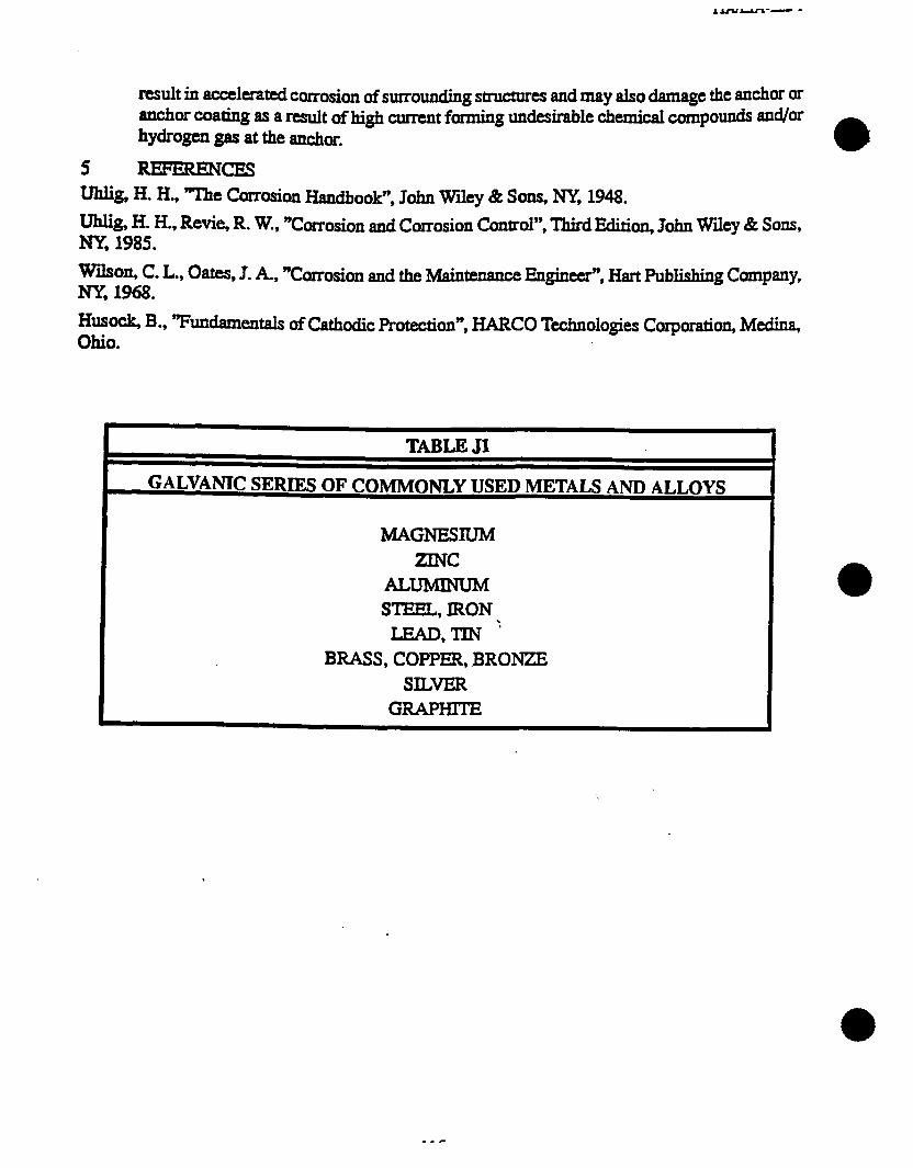
result in accelerated coxrosion of surrounding structures and may also damage the ax-&or or anchor coating as a result of&# current hning undeisirable chemical compounds and/or hydrogen gas at the anchor.
5 REFERENCES wg, H. H., “‘Ibe Corrosion Handbook”, John Wiley & Sons, NY, 1948. mg, H. H., Revie, R. W., “Corrosion and Corrosion Control”, Third Edition, John Whey Bi Sons, NY, 1985.
W&O% C. L., oat=, J. A, “Cmosion and the Maintenance Engineer”, Hart Publishing Company, NY, 1968.
Huock, B., “‘F~chmds of Cathodic Protection”, HARCO Technologies Corporation, Mexiina, Ohio.
TABLE Jl
GALVANIC SERIES OF COMMONLY USED METALS AND ALLOYS
MAGNESIUM ZINC
AL- STEEL, IRON
LEAD,m : BRASS, COPPER, ,BRONZE
SILVER GRAPHITE
a