eia for the proposed additional exploratory drilling in
TRANSCRIPT
EIA for the Proposed Additional Exploratory Drilling in NELP-I Block
KG-DW N-98/2, KG Offshore, Andhra Prade sh

EIA for the Proposed Additional Exploratory Drilling in NELP-I Block
KG-DW N-98/2, KG Offshore, Andhra Prade sh
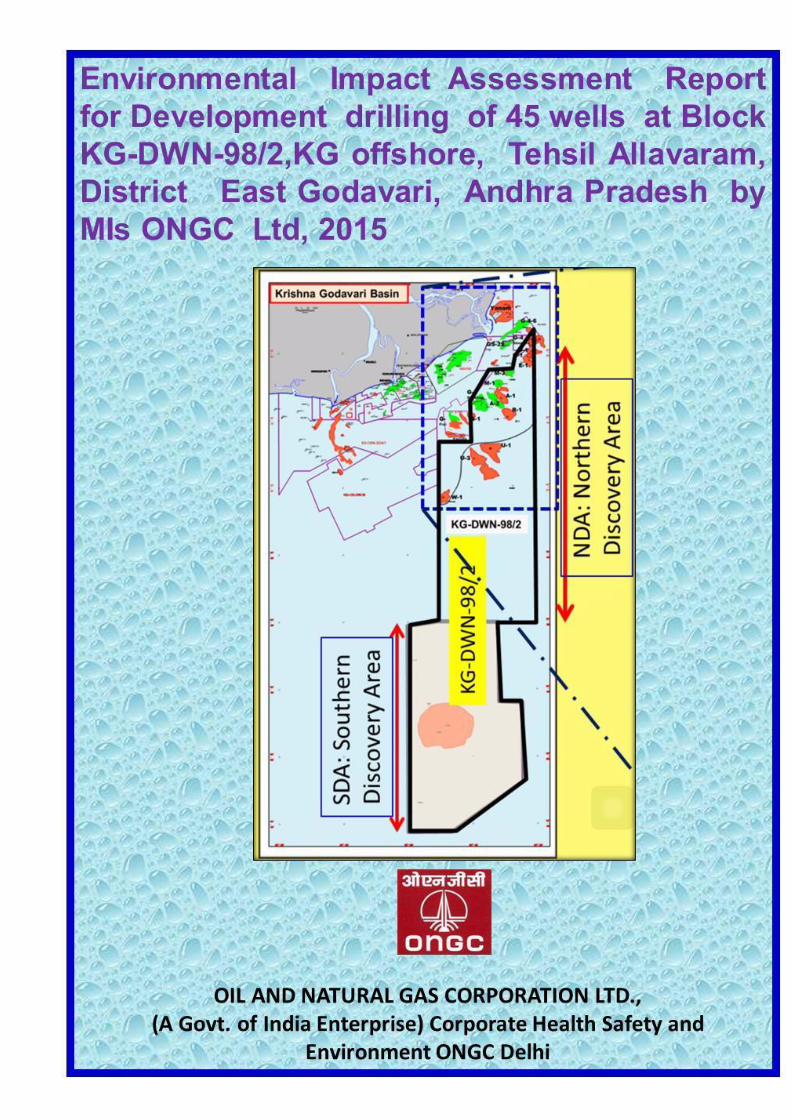
Environmental Impact Assessment Report for
Development drilling of 45 wells at Block KG-DWN-
98/2,KG offshore, Tehsil Allavaram, District East
Godavari, Andhra Pradesh by MIs ONGC Ltd
2015
Project Leader &QCI Accredited EIA Coordinator
Dr. J.S.Sharma
General Manager(Chem)
Corporate HSE, Delhi
Project Team
B.Phaneendra Babu Dr Sajid Jamal Debashis Chakravorty Deputy General Manager (Chem) Deputy General Manager Deputy General M a n a g e r
HSE, KG Basin Corporate HSE, Delhi MBA Basin, Kolkata
S.K.Lijhara J V H Prasad
Chief Chemist, Corporate HSE, Delhi I/c HSE, EOA, Kakinada
Other Associated Members in the project
Mrs Vartika Roy, Sh. Ashish Bhuwan , Sh Setu Goel
2015 Corporate Health Safety and Environment,
Oil and Natural Gas Corporation Ltd.
(A Govt. of India Enterprise),
8th
Floor, Scope Minar, South Tower, Laxmi Nagar, Delhi-110092
EIA for the Proposed Additional Exploratory Drilling in NELP-I Block
KG-DW N-98/2, KG Offshore, Andhra Prade sh
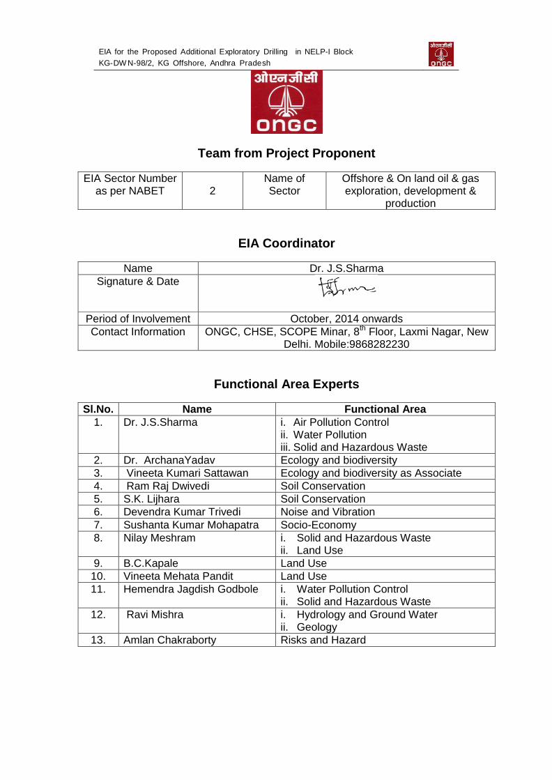
Team from Project Proponent
EIA Sector Number as per NABET 2
Name of Sector
Offshore & On land oil & gas exploration, development &
production
EIA Coordinator
Name Dr. J.S.Sharma
Signature & Date
Period of Involvement October, 2014 onwards
Contact Information ONGC, CHSE, SCOPE Minar, 8th Floor, Laxmi Nagar, New Delhi. Mobile:9868282230
Functional Area Experts
Sl.No. Name Functional Area
1. Dr. J.S.Sharma i. Air Pollution Control ii. Water Pollution iii. Solid and Hazardous Waste
2. Dr. ArchanaYadav Ecology and biodiversity
3. Vineeta Kumari Sattawan Ecology and biodiversity as Associate
4. Ram Raj Dwivedi Soil Conservation
5. S.K. Lijhara Soil Conservation
6. Devendra Kumar Trivedi Noise and Vibration
7. Sushanta Kumar Mohapatra Socio-Economy
8. Nilay Meshram i. Solid and Hazardous Waste ii. Land Use
9. B.C.Kapale Land Use
10. Vineeta Mehata Pandit Land Use
11. Hemendra Jagdish Godbole i. Water Pollution Control ii. Solid and Hazardous Waste
12. Ravi Mishra i. Hydrology and Ground Water ii. Geology
13. Amlan Chakraborty Risks and Hazard

EIA for the Proposed Additional Exploratory Drilling in NELP-I Block
KG-DW N-98/2, KG Offshore, Andhra Prade sh
FOREWORD
The operational area in KG Basin Rajahmundry covers an area
of 28000 sq. km. onland and 1,45,000 sq. km. of offshore,
including deep waters. This is a unique basin in the sense that
hydrocarbons have been discovered in the geologically oldest
(250 Million years) to the youngest (5 million years) sediments
and from both onland and offshore parts of the basin. Till date
more than 600 onland wells and 200 offshore wells have been
drilled overcoming the challenges of high pressure, high
temperature and other drilling problems.
The " Environmental Impact Assessment Report for Development
drilling of 45 wells at Block KG-DWN-98/2,KG offshore, Tehsil
Allavaram, District East Godavari, Andhra Pradesh by MIs
ONGC Ltd" has been prepared by the team of Dr. JS Sharma,
General Manager(Chemistry), Corporate Health Safety &
Environment (CHSE), ONGC, New Delhi & QCI approved EIA
Coordinator and Functional Area Expert, & his team based on
various field studies and data collected from various
Government agencies.
ONGC is committed to operate responsibly by implementing
environmentally sound technologies and practical solutions
for energy security of India in a sustainable way. The point
wise compliance o f the TOR has been given in the report.
This report is being submitted for grant of Environmental
Clearance.
M C DAS ED Chief HSE, ONGC
EIA for the Proposed Additional Exploratory Drilling in NELP-I Block
KG-DW N-98/2, KG Offshore, Andhra Prade sh
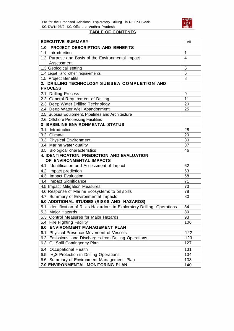
TABLE OF CONTENTS
EXECUTIVE SUMM ARY i-vii
1.0 PROJECT DESCRIPTION AND BENEFITS 1.1. Introduction 1 1.2. Purpose and Basis of the Environmental Impact
Assessment 4
1.3 Geological setting 5 1.4 Legal and other requirem ents 6 1.5 Project Benefits 8 2. DRILLING TECHNOLOGY SUBSEA C OMPLET ION AND PROCESS
DESCRIPTION
2.1. Drilling Process 9 2.2. General Requirement of Drilling 11 2.3 Deep W ater Drilling Technology 20 2.4 Deep W ater W ell Abandonment 25 2.5 Subsea Equipment, Pipelines and Architecture
2.6 Offshore Processing Facilities
3 BASELINE ENVIRONMENTAL STATUS 3.1 Introduction 28 3.2. Climate 29 3.3 Physical Environment 30 3.4 Marine water quality 37 3.5 Biological characteristics 46 4. IDENTIFICATION, PREDICTION AND EVALUATION
OF ENVIRONMENTAL IMPACTS
4.1 Identification and Assessment of Impact 62 4.2 Impact prediction 63 4.3 Impact Evaluation 68 4.4 Impact Significance 71
4.5 Impact Mitigation Measures 73 4.6 Response of Marine Ecosystems to oil spills 78 4.7 Summary of Environmental Impacts 80 5.0 ADDITIONAL STUDIES (RISKS AND HAZARDS) 5.1 Identification of Risks Hazardous in Exploratory Drilling Operations 84 5.2 Major Hazards 89 5.3 Control Measures for Major Hazards 93 5.4 Fire Fighting Facility 106 6.0 ENVIRONMENT MANAGEMENT PLAN 6.1 Physical Presence Movement of Vessels 122 6.2 Emissions and Discharges from Drilling Operations 123 6.3 Oil Spill Contingency Plan 127
6.4 Occupational Health 131 6.5 H2S Protection in Drilling Operations 134 6.6 Summary of Environment Management Plan 138 7.0 ENVIRONMENTAL MONITORING PLAN 140
EIA for the Proposed Additional Exploratory Drilling in NELP-I Block
KG-DW N-98/2, KG Offshore, Andhra Prade sh
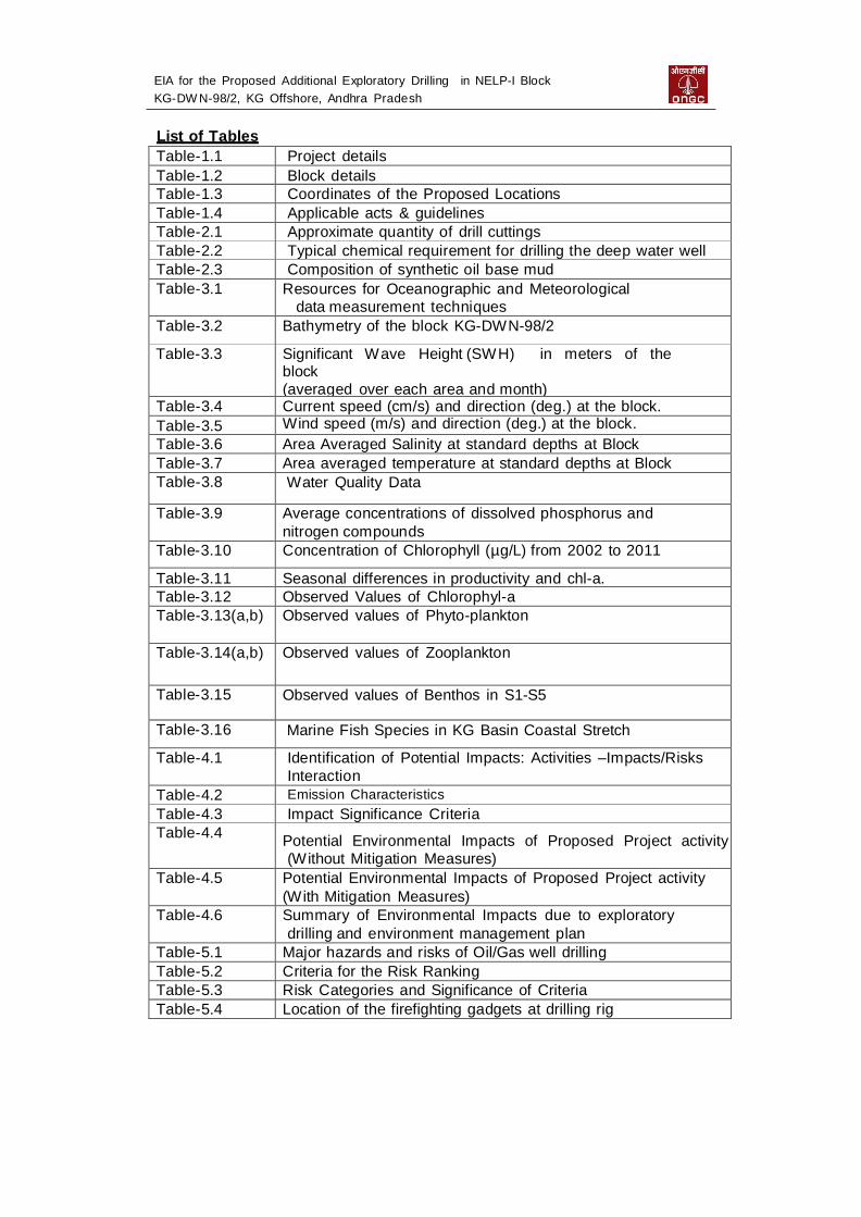
List of Tables
Table-1.1 Project details Table-1.2 Block details Table-1.3 Coordinates of the Proposed Locations Table-1.4 Applicable acts & guidelines Table-2.1 Approximate quantity of drill cuttings Table-2.2 Typical chemical requirement for drilling the deep water well Table-2.3 Composition of synthetic oil base mud Table-3.1 Resources for Oceanographic and Meteorological
data measurement techniques Table-3.2 Bathymetry of the block KG-DW N-98/2
Table-3.3 Significant W ave Height (SW H) in meters of the block (averaged over each area and month)
Table-3.4 Current speed (cm/s) and direction (deg.) at the block. Table-3.5 Wind speed (m/s) and direction (deg.) at the block.
Table-3.6 Area Averaged Salinity at standard depths at Block Table-3.7 Area averaged temperature at standard depths at Block Table-3.8 W ater Quality Data
Table-3.9 Average concentrations of dissolved phosphorus and
nitrogen compounds Table-3.10 Concentration of Chlorophyll (µg/L) from 2002 to 2011
Table-3.11 Seasonal differences in productivity and chl-a. Table-3.12 Observed Values of Chlorophyl-a Table-3.13(a,b) Observed values of Phyto-plankton
Table-3.14(a,b) Observed values of Zooplankton
Table-3.15 Observed values of Benthos in S1-S5
Table-3.16 Marine Fish Species in KG Basin Coastal Stretch
Table-4.1 Identification of Potential Impacts: Activities –Impacts/Risks
Interaction Table-4.2 Emission Characteristics
Table-4.3 Impact Significance Criteria Table-4.4
Potential Environmental Impacts of Proposed Project activity (W ithout Mitigation Measures)
Table-4.5 Potential Environmental Impacts of Proposed Project activity
(W ith Mitigation Measures) Table-4.6 Summary of Environmental Impacts due to exploratory
drilling and environment management plan Table-5.1 Major hazards and risks of Oil/Gas well drilling Table-5.2 Criteria for the Risk Ranking Table-5.3 Risk Categories and Significance of Criteria Table-5.4 Location of the firefighting gadgets at drilling rig

EIA for the Proposed Additional Exploratory Drilling in NELP-I Block
KG-DW N-98/2, KG Offshore, Andhra Prade sh
Table-5.5 Identification of various hazards, its consequences and
prevention and mitigations measures of exploratory drilling Table-6.1 Occupational Health hazards and mitigating measures Table-6.2 Periodicity of PME Table-7.1 Environmental Monitoring
List of Figures
Fig-1.1 Oil & Gas fields of KG Basin Fig-1.2 Map showing the proposed drilling locations and distance of the
blocks from the coast Fig- 2.1 Typical offshore Drill Ship Fig-2.2 Mud Circulation system
Fig-3.1 Significant wave height in the block Fig:3.2 Current speed and direction at the block
Fig-3.3 Wind rose diagram showing wind directions in the block KG-DW N-
98/2.
Fig:3.4 Sampling Locations of the block KG-DWN-98/2
Fig-3.5 Surface distribution of salinity
Fig-3.6 Sea surface temperature
Fig-3.7 Sea water collection at different sampling points
Fig-5.1 Risk Ranking Matrix
Fig-5.2 Sub Surface Oil S pill Plume
Fig-5.3 Oil / Gas W ell Blow-out Communication Flow Chart
LIST OF ANNEXURES
I Blowout Control Equipment and Case study of Deep water Horizon
Rig II Oil Spill Contingency Plan III TORs issued by MoEF vide EAC Agenda No.10.2.33 IV Form-1 NELP- I Offshore block KG-DW N-98/2 V Copy of the Existing EC VI Six monthly Compliance report for the existing EC VII Google map showing the nearest drilling locations of the block from
the coast VIII Emission calculations
EIA for Development Drilling of 45 wells at Block KG-DWN-98/2, KG Offshore in NELP-I Block
KG-DWN-98/2, KG Offshore, Andhra Pradesh
1
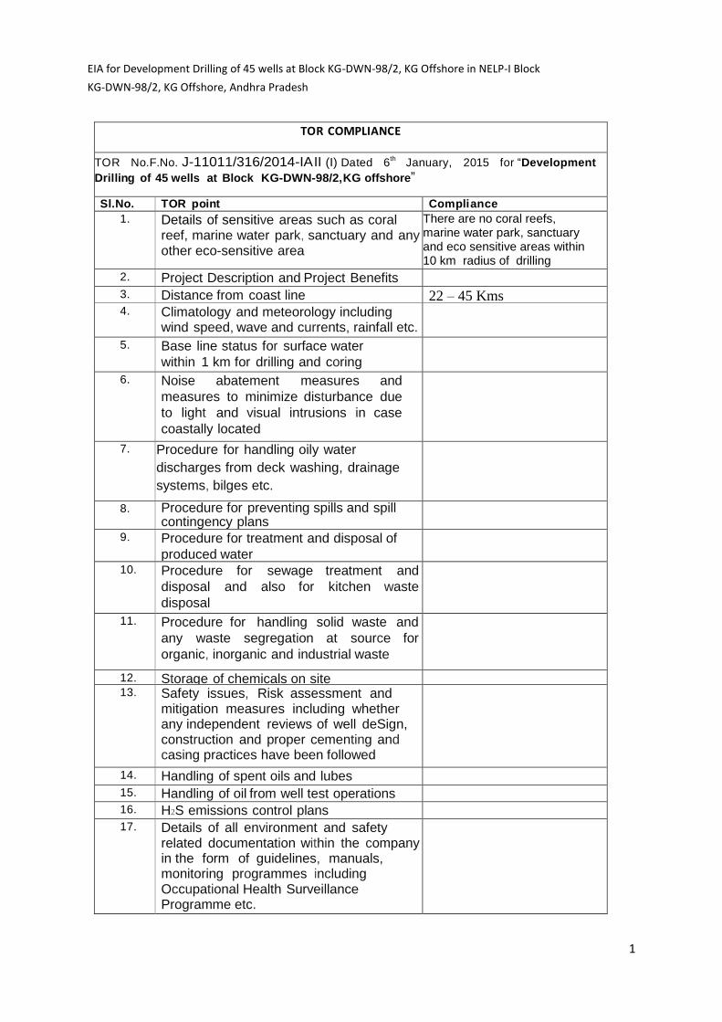
TOR COMPLIANCE
TO R No.F.No. J-11011/316/2014-IA II (I) Dated 6th
January, 2015 for “Development
Drilling of 45 wells at Block KG-DWN-98/2,KG offshore”
Sl.No. TOR point Compli ance 1. Details of sensitive areas such as coral
reef, marine water park, sanctuary and any other eco-sensitive area
There are no coral reefs, marine water park, sanctuary and eco sensitive areas within 10 km radius of drilling
locations (Annex-vii) 2. Project Description and Project Benefits
3. Distance from coast line 22 – 45 Kms 4. Climatology and meteorology including
wind speed, wave and currents, rainfall etc.
5. Base line status for surface water
within 1 km for drilling and coring
site, particularly in respect of oil
content
6. Noise abatement measures and
measures to minimize disturbance due
to light and visual intrusions in case
coastally located
7. Procedure for handling oily water
discharges from deck washing, drainage
systems, bilges etc.
8. Procedure for preventing spills and spill contingency plans
9. Procedure for treatment and disposal of
produced water
10. Procedure for sewage treatment and
disposal and also for kitchen waste
disposal
11. Procedure for handling solid waste and
any waste segregation at source for
organic, inorganic and industrial waste
12. Storage of chemicals on site 13.
Safety issues, Risk assessment and mitigation measures including whether any independent reviews of well deSign, construction and proper cementing and casing practices have been followed
14. Handling of spent oils and lubes
15. Handling of oil from well test operations
16. H2S emissions control plans
17. Details of all environment and safety related documentation within the company in the form of guidelines, manuals, monitoring programmes including Occupational Health Surveillance Programme etc.

EIA for Development Drilling of 45 wells at Block KG-DWN-98/2, KG Offshore in NELP-I Block
KG-DWN-98/2, KG Offshore, Andhra Pradesh
2
18. Restoration plans and measures to be
taken for decommissioning of the rig
19. A note on identification and
implementation of Carbon Credit project if
any should be included
20. CRZ clearance, if any, may be obtained wherever applicable for offshore to onshore
activities
21. A tabular chart with index for point-wise
compliance of above TORs

EIA for Development Drilling of 45 wells at Block KG-DWN-98/2, KG Offshore in NELP-I Block
KG-DWN-98/2, KG Offshore, Andhra Pradesh
3
EXECUTIVE SUMMARY
This EIA report is prepared in line with Ministry of Environment and Forests
(MoEF) approved Terms of Reference (TOR) vide F.No. J-11011/316/2014-IA II (I)
Dated 6th January, 2015 for “Development Drilling of 45 wells at Block KG-
DWN-98/2, KG offshore” during their meeting of 26th Reconstituted Expert
Appraisal Committee (Industry) held during 29th - 30th October, 2014 against agenda
point 26.4.10, for preparation of EIA/EMP report. The NELP-I offshore block KG-DW
N-98/2 is located off the coast of Godavari Delta in the east coast of India.
The present report is being submitted for Environment Clearance to the
development drilling of 45 wells, Floating, Production, Storage and Offloading
(FPSO), Offshore Platform, Subsea Equipment and Pipelines in NELP-I block KG-
DWN-98/2 in the KG Basin, Andhra Pradesh. The project details are as follows:
The purpose of this study is to assess the environmental impacts arising due to
development drilling of proposed 45 wells, Floating, Production, Storage and
Offloading (FPSO), Offshore Platform, Subsea Equipment and Pipelines in this
block. ONGC has instituted following studies for baseline as per prescribed TOR.
I. Collection for surface water for one season leaving the monsoon
season within 1km of each exploratory well, particularly in respect of oil content.
II. Meteorological and climatological data has been finalized based on primary
& secondary data from the Indian National Centre for Ocean Information
Services (INCOIS). (ONGC has institutionalized relationship with INCOIS)
III. There are no sensitive areas located near the block.
In addition to above, TOR’s related to procedures on Waste management, Oil
Spill and Blow Out prevention etc. have also been prescribed.

EIA for Development Drilling of 45 wells at Block KG-DWN-98/2, KG Offshore in NELP-I Block
KG-DWN-98/2, KG Offshore, Andhra Pradesh
4
1.0 Project Description
Offshore part of the Krishna Godavari Basin categorized as shallow and deep
waters, covers the area of Srikakulam coast in the north to off Nellore in the
south and is considered as highly prospective for Hydrocarbon exploration.
Exploration efforts carried out so far in this block has led to discovery of
hydrocarbons in the entire block and established Northern Discovery Area
(NDA) with significant discoveries like Annapurna (R-1), Kanakadurga (G2P1),
Padmavati (M1) etc. and Southern Discovery Area (SDA) with UD-1. Present
proposal is for deve lopment drilling of 45 wells for r e a l i s i n g t h e
re se r ve s of the block. The water depth in this area of the block ranges from
320 m to 3100m. However, there are no eco-sensitive areas or forest or wild life
sanctuaries within the 10 km study area.
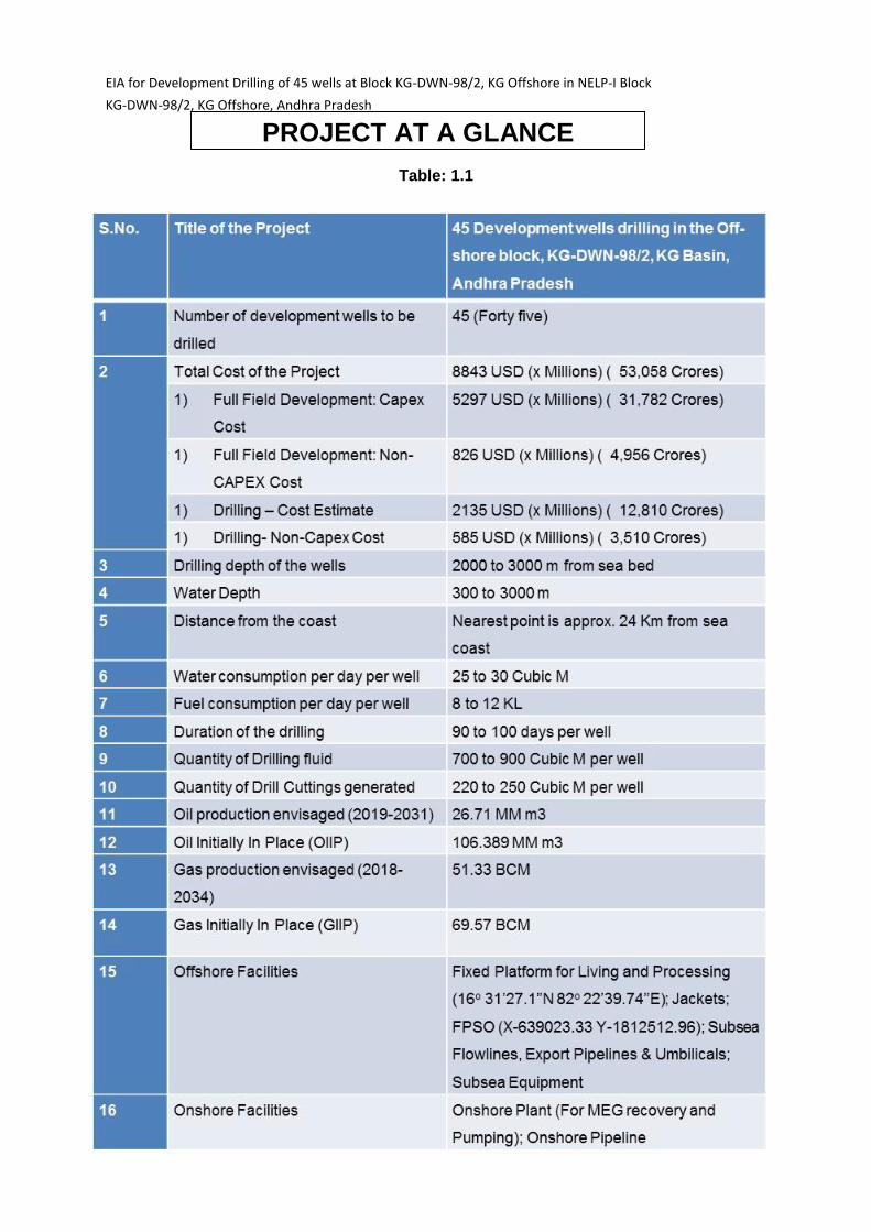
1.1 Project at a Glance

EIA for Development Drilling of 45 wells at Block KG-DWN-98/2, KG Offshore in NELP-I Block
KG-DWN-98/2, KG Offshore, Andhra Pradesh
5
1.2 Existing facility & Development Plan
There is an existing terminal at Odalarevu, and coordinates for the existing G-1 10”
export flow line shore crossing.
Cluster-1 Development Plan: The produced Gas from this cluster is proposed to be
taken to a Fixed Platform (located at 16o 31’27.1”N 82o 22’39.74”E +/- 3 kms) in
shallow water depths, through 18” – 16.1 Kms Dual Pipeline and treated as per the
process plan (as detailed in following text), compressed and subsequently evacuated
to Odalarevu onshore terminal through 20” – 35.5 Kms Pipeline for sales to GAIL
(Gas Authority of India Limited) custody transfer point.
Cluster-2 Development Plan
The produced Oil from Cluster-2 is proposed to be taken on to an FPSO (Floating
Production Storage and Offloading) anchored/moored (Located at 16 o 20’ 46’’ N, 82
o 18’ 55’’E +/- 3 Km), through 18” – 21.5 Kms Dual Pipeline. The Oil with associated
Gas is treated for separation of Oil, Gas and Water on FPSO as detailed in Process
plan given below and the stabilized crude oil is transported through sea tankers
and dehydrated Gas is evacuated on to Fixed platform, through 18” – 21.4 Kms
Dual Pipeline with an option of evacuating from FPSO to Odalarevu Onshore
Terminal through 22” – 34.3 Kms Pipeline for sales to GAIL custody Transfer point.
Process Description:
Well Fluid will be transported to the GAIL custody transfer meter point for sales
through subsea pipelines (20” pipeline from Fixed Platform and 22” Pipe line from
FPSO) up to landfall point and from landfall to MEG (Methyl Ethylene Glycol)
recovery plant located in the existing Vashishta & S1 Plant at Odalarevu Onshore
plant.
2.0 Drilling Technology
As this proposed block is located in deep and ultra-deep water, drill ship with
Dynamic Positioning (DP) and specialized deep water technology tools will be used
for drilling. Presence of extreme temperature and pressures at these depths,
special drilling muds are used to prevent formation of hydrates at the sea bed level

EIA for Development Drilling of 45 wells at Block KG-DWN-98/2, KG Offshore in NELP-I Block
KG-DWN-98/2, KG Offshore, Andhra Pradesh
6
and to combat dual gradients. Glycol based drilling mud to be used for the
prevention of hydrate formation in these wells. Initially the well was drilled with
water based mud system and Synthetic Oil Based Mud (SOBM) with low toxicity
LC>50,000 (mysid toxicity) is also used in sections having specific borehole
problems. Drilling mud circulated in the system is continuously treated at the
surface after removal of drilled solids with sophisticated solids removal
equipment and re-circulated back in to the system. SOBM is completely
recovered and transported to another site and is not disposed into sea. Thoroughly
washed cuttings are discharged into the sea.
3.0 Baseline Environment
In this report, the baseline environment description includes collection of primary
and secondary data through field investigations, environmental monitoring,
scientific literature, reports and maps etc. The collected data/information has been
analysed for identification of impacts and arrives at mitigation measures for
minimizing the any adverse environmental impacts due to the proposed
exploratory drilling activities.
W ith this view, baseline physico-chemical parameters of sea water such as
pH, Salinity, dissolved oxygen, inorganic nutrients (nitrates and
phosphates), trace elements, petroleum hydrocarbons etc. are studied. The
occurrence of marine species - both flora and fauna has largely been controlled by
the physico-chemical properties of sea water. In view of wide variations in
biological production in a marine ecosystem, the biological parameters considered
for the present evaluation are phytoplankton (pigments, population and dominant
genera), zooplankton (biomass, population and faunal groups), macro benthos
(biomass, population and faunal groups) and status of fishery.
Climate Over this block which is located at the distance of 28-250 km from the coast, the
northeast monsoon is from November through April as continental high
pressure system in north of the bay produces northeast winds characteristic

EIA for Development Drilling of 45 wells at Block KG-DWN-98/2, KG Offshore in NELP-I Block
KG-DWN-98/2, KG Offshore, Andhra Pradesh
7
of the winter season. During the northern summer (June–September) the rain-
bearing southwest monsoon prevails, as intense heat produces a low-pressure
system over the continent and a subsequent air flow from the ocean. North
east monsoon and cyclonic storms over the Bay of Bengal along South East
coast of Peninsular India bring heavy rainfall associated with major physical
changes.
3.1 Physical Environment
ONGC has shared information& knowledge about Oceanographic and
Meteorological data for the block area with premier national institute INCOIS,
Hyderabad. The data for Bathymetry, Significant Wave Height, Surface Ocean
Currents, W ind speeds, Salinity and Temperature is real time data monitored
by satellites.The most important processes that control the dynamics of the sea
which are directly linked with the transport of the pollutants are tides, waves,
winds and currents. The average significant wave height ranges from 0.4 m to
1.5 m in the block area. The wind speeds has a maximum value of 5.4 m/s
during south west monsoon. The currents are oriented in the northerly direction
most of the time (avg. speed). The currents are intense during the southwest
monsoon and post monsoon months has a maximum speed of 47.7 cm/s. The
currents in the Bay of Bengal are intense close to the coast mainly because of
the eddies – “warm” core and “cold” core as well as the alongshore intense
gradients in the thermo-haline characteristics because of the substantial river
discharge of major river systems.
3.2 Marine Water Quality
The area of the block KG-DWN-98/2 is largely oceanic and therefore not
expected to undergo significant changes in water quality, temporarily as well
as spatially. Parameters like pH, Salinity and dissolved oxygen are in the range
of typical Bay values due to farther-ness from the coast and subject to less coastal
influences. The surface salinity in the open part of the Bay oscillates from 32 ppt
to 34 ppt (i.e parts per thousand). The observed values of the pH, salinity and
dissolved oxygen are in the range of 7.6-7.9, 32.9 to 33.9 ppt. and 6.0 to 6.3 mg/l

EIA for Development Drilling of 45 wells at Block KG-DWN-98/2, KG Offshore in NELP-I Block
KG-DWN-98/2, KG Offshore, Andhra Pradesh
8
respectively. There is a considerable variation in the observed values of
NO3-2 (9.96-12.02 µmol/l) and PO4
-3 (2.34 – 2.98 µmol/l) nutrient levels with
that of reported for the near-shore coastal waters. Most of the heavy metals
analysed are below their detection limits. The concentrations of dissolved and
dispersed Petroleum hydrocarbons (PHC) in the study area are low and
uniformly distributed (2.6 to 3.9 µg/l).
3.3 Biological Environment The occurrence of marine species - both flora and fauna has largely been
controlled by the physico-chemical properties of sea water. In view of wide
variations in biological production in a marine ecosystem, the biological
parameters considered for the present evaluation are phytoplankton (pigments,
population and dominant genera), zooplankton (biomass, population and faunal
groups), macro benthos (biomass, population and faunal groups) and also
status of fishery. The phyto pigment concentration, diversity index and density
in the study area shows marked variation in the block. Sampling locations S1-S5
which are relatively near to the coast and shows high pigment concentration
(6.57-7.88 µgl-1). Whereas, at points S6-S8, which are far from the coast and has
low pigment concentration (0.31-0.89). The dominant fish species in the
area are Elasmobrabches, Clupedis, Peachis, Flast Fishes, Drift Fishes,
Carangids, Seerfishes Oceanic Tunas, Neritic Tunas, Mackerals Pomfrets ,
Deepsea Fishes, Lobosters, Cephalopods and other marine mammals- Shrimp
(Littoral), Other Crustaceans and Shrimp (Deep sea).
4.0 Identification, Prediction and Evaluation of I m pa c ts Presence of the rig in the deep sea environment has an overall positive impact
as it can be used as a fish aggregating device. Impacts of air emissions and other
routine activities are expected to be below prescribed levels. Available
information in this area does not indicate the presence of any protected habitat or
endangered species. Impacts on marine water quality has been envisaged to be
insignificant as the wastewater and drill cuttings from the drilling & other activities

EIA for Development Drilling of 45 wells at Block KG-DWN-98/2, KG Offshore in NELP-I Block
KG-DWN-98/2, KG Offshore, Andhra Pradesh
9
shall be treated to meet requirements of stipulated standards prior to its disposal.
Based on the baseline data of this area and other studies carried out
for aforementioned parameters, it can be concluded that under the normal operating
conditions there will not be any significant marine environmental impact due
to proposed development drilling
5.0 Risk Assessment & Mitigations Measures Major risks associated with the deep water drilling are blowout, oil spill,
hydrate formation due to low temperature/high pressure, loss of hydrostatic head
due to riser disconnect and passing vessel hitting the rig. To prevent hydrate
formation glycol based muds are used for deep water drilling. For containment of oil
spill, the contingency plan has been developed. There is a full-fledged Crisis
Management Team (CMT) for blow out and dedicated contingency plan for H2S
em iss ion .
6.0 Environmental Management Plan Offshore drilling operations may interact with marine environment and may result in
physical, chemical and biological changes. Impacts of these changes, if any are
to be mitigated by adopting standards as suggested in TOR, CPCB Standards, as
per provisions of Merchant Sipping Act and MARPOL. The offshore drilling
operation generates two major and three minor waste streams. The major waste
streams are drilling fluids and drill cuttings. The minor waste streams are of deck
drainage, sanitary waste and domestic waste etc. Water based muds will be
recycled to maximum possible extent and non-usable portion will be discharged
intermittently (50 bbl/hr) in sea with proper dilution. SOBM will be completely
recycled and reused. Sanitary waste is treated in the sewage treatment plants
of the drilling rig and disposed to sea after maintaining the required disposal
parameters. W aste water generated during drilling operations will be 30-35
m 3/day. Kitchen waste is separated into bio-degradable and non-biodegradable
components. Non- biodegradable waste is packed, labelled and sent to land
base for further safe disposal.

EIA for Development Drilling of 45 wells at Block KG-DWN-98/2, KG Offshore in NELP-I Block
KG-DWN-98/2, KG Offshore, Andhra Pradesh
10
CHAPTER-1
Project Description and Benefits
1.0 Introduction
Krishna Godavari Basin, offshore categorized as shallow and deep waters, covers the area
of Sriakulam coast in the north to off Nellore in the south and is considered highly
prospective for Hydrocarbon exploration point of view. It is a unique basin as hydrocarbon
occurrences are in the entire geological sedimentary sequence. Exploration effort carried out
in the block has enabled converting the area into discovery area by successful discovery of
hydrocarbons in the entire block.
Present proposal is being submitted for obtaining Environmental Clearance (EC):
To drill 45 development wells
Floating Production Storage and Offloading (FPSO)
Offshore Fixed Platform
Subsea Production Systems (SPS) and Subsea Pipelines connecting to Landfall
point to existing onshore terminal for custody transfer to GAIL.
This EIA report is prepared in line with Ministry of Environment and Forests (MoEF)
approved Terms of Reference (TOR) vide F.No. J-11011/316/2014-IA II (I) Dated 6th
January, 2015 for “Development Drilling of 45 wells at Block KG-DWN-98/2, KG
offshore” during their meeting of 26th Reconstituted Expert Appraisal Committee (Industry)
held during 29th - 30th October, 2014 against agenda point 26.4.10, for preparation of
EIA/EMP report. The NELP-I offshore block KG-DW N-98/2 located off the coast of
Godavari Delta in the east coast of India.
EIA for Development Drilling of 45 wells at Block KG-DWN-98/2, KG Offshore in NELP-I Block
KG-DWN-98/2, KG Offshore, Andhra Pradesh
11
Earlier Environmental Clearance Status of the Block
As per the Environmental Clearances, initially the permission was granted for
exploratory drilling of twenty wells (nine + eleven) in two trenches to M/s Cairn
Energy (India) Limited (CEIL) vide EC No.J-11011/18/2004-IA II (I) dated 8th
December’2004.
CEIL has initially drilled six exploratory wells. After acquiring the operatorship,
ONGC has drilled the remaining fourteen exploratory wells. Subsequently, ONGC
was granted Environmental Clearances vide EC Nos.J-11011/474/2010-IA II (I)
dated11th May’2011 and J-11011/70/2011-IA II (I) dated 4thSeptember’ 2012 for
drilling three and seven exploratory wells respectively.
Recently ONGC has obtained EC for drilling of 10 exploratory/appraisal wells
through vide EC No. J-11011/189/2013-IA II (I) dated 24th January’ 2014 , during the
13th re-constituted EAC (MoEF) agenda meeting held on 19th November’2013 for
the total 39 wells.

EIA for Development Drilling of 45 wells at Block KG-DWN-98/2, KG Offshore in NELP-I Block
KG-DWN-98/2, KG Offshore, Andhra Pradesh
12
1.1 Project Description
The KG-DWN-98/2 Block
covers area of 7294.6 sq.
km. ONGC intends to
develop the NELP-I Block
KG-DWN-98/2 in deep
waters off east coast of
India. The KG-DWN-98/2
block is located within 25-
80 km from the nearest
coastline. The discovery
area of the block has been
categorized as Northern
Discovery Area (NDA-
3800.6 Sq km) and
Southern Discovery
Area (SDA-3494 Sq km)
Fig: 1. The water depth in
this block varies between
300 metres to 3200
metres. A location map
identifying the KG-DWN-
98/2 development area is
is given in Fig:2.
Fig:1 Location map of the block
EIA for Development Drilling of 45 wells at Block KG-DWN-98/2, KG Offshore in NELP-I Block
KG-DWN-98/2, KG Offshore, Andhra Pradesh
13
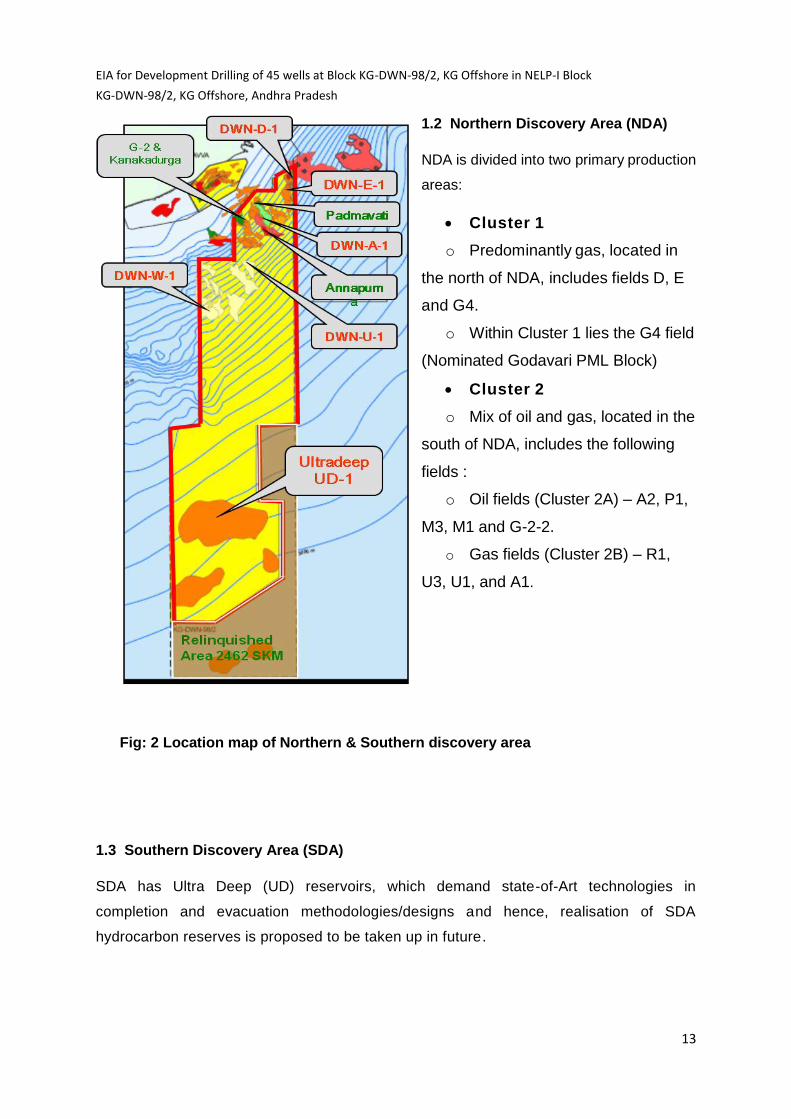
1.2 Northern Discovery Area (NDA)
NDA is divided into two primary production
areas:
Cluster 1
o Predominantly gas, located in
the north of NDA, includes fields D, E
and G4.
o Within Cluster 1 lies the G4 field
(Nominated Godavari PML Block)
Cluster 2
o Mix of oil and gas, located in the
south of NDA, includes the following
fields :
o Oil fields (Cluster 2A) – A2, P1,
M3, M1 and G-2-2.
o Gas fields (Cluster 2B) – R1,
U3, U1, and A1.
Fig: 2 Location map of Northern & Southern discovery area
1.3 Southern Discovery Area (SDA)
SDA has Ultra Deep (UD) reservoirs, which demand state-of-Art technologies in
completion and evacuation methodologies/designs and hence, realisation of SDA
hydrocarbon reserves is proposed to be taken up in future.
EIA for Development Drilling of 45 wells at Block KG-DWN-98/2, KG Offshore in NELP-I Block
KG-DWN-98/2, KG Offshore, Andhra Pradesh
14
Table: 1.1
PROJECT AT A GLANCE
EIA for Development Drilling of 45 wells at Block KG-DWN-98/2, KG Offshore in NELP-I Block
KG-DWN-98/2, KG Offshore, Andhra Pradesh
15
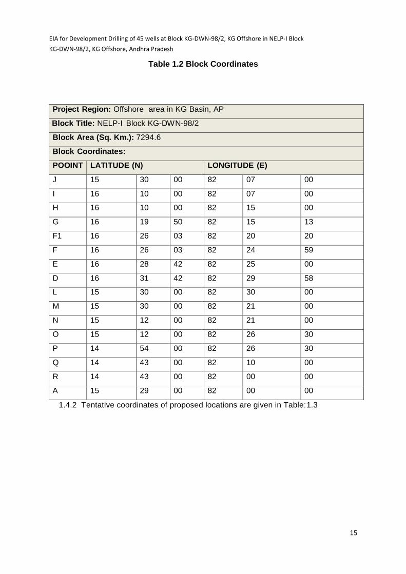
Table 1.2 Block Coordinates
1.4.2 Tentative coordinates of proposed locations are given in Table:1.3
Project Region: Offshore area in KG Basin, AP
Block Title: NELP-I Block KG-DWN-98/2
Block Area (Sq. Km.): 7294.6
Block Coordinates:
POOINT LATITUDE (N) LONGITUDE (E)
J 15 30 00 82 07 00
I 16 10 00 82 07 00
H 16 10 00 82 15 00
G 16 19 50 82 15 13
F1 16 26 03 82 20 20
F 16 26 03 82 24 59
E 16 28 42 82 25 00
D 16 31 42 82 29 58
L 15 30 00 82 30 00
M 15 30 00 82 21 00
N 15 12 00 82 21 00
O 15 12 00 82 26 30
P 14 54 00 82 26 30
Q 14 43 00 82 10 00
R 14 43 00 82 00 00
A 15 29 00 82 00 00

EIA for Development Drilling of 45 wells at Block KG-DWN-98/2, KG Offshore in NELP-I Block
KG-DWN-98/2, KG Offshore, Andhra Pradesh
16
Table: 1.3 Tentative Coordinates of the proposed locations
Coordinates of locations, KG-DWN-98/2 and G-4
Gas Field Well Latitude Longitude
DWN-A A-1-A 16° 20' 7.517" N 82° 21' 38.576" E
DWN-D D-1-A 16° 29' 55.227" N 82° 29' 14.848" E
D-1-B 16° 30' 34.011" N 82° 28' 58.613" E
DWN-E DWN-E-1 16° 28' 13.214" N 82° 28' 38.136" E
DWN-R-1 R-1-A 16° 16' 3.938'N 82° 23' 9.944'E
R-1-B 16° 15' 51.321" N 82° 23' 28.623' E
R-1-C 16 ° 17' 44.450" N 82° 22' 44.112" E
DWN-U-1 U-1-A 16° 7' 51.015" N 82° 18' 57.143" E
U-1-B 16° 8' 5.105" N 82° 18' 29.714" E
DWN-U-3 DWN-U-3 16° 8' 14.190" N 82° 16' 59.708" E
U-3-A 16° 7' 42.329" N 82° 15' 52.336" E
G-4 G-4-A 16° 31' 53.116" N 82° 29' 31.204" E
G-4-B 16° 32' 10.589" N 82° 30' 17.666" E
G-4-C 16° 32' 51.717" N 82° 30' 35.975" E
G-4-D 16° 33' 18.330" N 82° 28' 28.822" E
Oil Field Well Latitude Longitude
DWN-A-2 DWN-A-2 16° 19' 37.557" N 82° 21' 0.997" E
A-2-A 16° 19' 20.798" N 82° 21' 3.590" E
A-2-B 16° 18' 31.924" N 82° 21' 46.561" E
A-2-C 16° 18' 43.880" N 82° 22' 8.171" E
A-2-D 16° 19' 18.594" N 82° 20' 29.044" E
A-2-E 16° 20' 27.104" N 82° 19' 34.920" E
A2-WI-A 16° 20' 0.204" N 82° 21' 2.612" E
A2-WI-B 16° 19' 15.226" N 82° 21' 42.344" E
A2-WI-C 16° 19' 27.764" N 82° 19' 54.801" E

EIA for Development Drilling of 45 wells at Block KG-DWN-98/2, KG Offshore in NELP-I Block
KG-DWN-98/2, KG Offshore, Andhra Pradesh
17
A2-WI-D 16° 19' 47.021" N 82° 20' 1.070" E
Kanakadurga P-1-A 16° 18' 15.829" N 82° 17' 46.643" E
P-1-B 16° 18' 15.850" N 82° 17' 8.301" E
P-1-C 16° 18' 50.411" N 82° 18' 39.429" E
P-1-D 16° 19' 9.378" N 82° 16' 10.360" E
DWN-P-1 16° 18' 31.422" N 82° 17' 23.280" E
P1-WI-A 16° 17' 53.483" N 82° 18' 2.493" E
P1-WI-B 16° 19' 8.427" N 82° 16' 53.348" E
P1-WI-C 16° 19' 28.282" N 82° 15' 47.956" E
DWN-M-1 M-1 16° 23' 4.481" N 82° 21' 39.312" E
M-1-WI-A 16° 23' 34.105" N 82° 21' 55.371" E
DWN-M-3 M-3-A 16° 25' 30.982" N 82° 23' 48.095" E
M-3-B 16° 25' 6.492" N 82° 23' 43.695" E
M3-WI-A 16° 25' 11.314" N 82° 24' 9.223" E
M3-WI-B 16° 25' 49.361" N 82° 23' 54.496" E
G-2-2 G-2-2-A 16° 18' 58.778" N 82° 17' 52.474"E
G-2-2-WI-A 16° 18' 40.367" N 82° 18' 25.834"E
Locations are about 22 to 45 km from reference point Odalarevu and are oriented towards NE & SE.
1.4 Cluster-1 Development Plan
The produced Gas from this cluster is proposed to be taken to a Fixed Platform (located at
16o 31’27.1”N 82o 22’39.74”E +/- 3 kms) in shallow water depths, through 18” – 16.1 Kms
Dual Pipeline and treated as per the process plan (as detailed in following text), compressed
and subsequently evacuated to Odalarevu onshore terminal through 20” – 35.5 Kms
Pipeline for sales to GAIL (Gas Authority of India Limited) custody transfer point.
EIA for Development Drilling of 45 wells at Block KG-DWN-98/2, KG Offshore in NELP-I Block
KG-DWN-98/2, KG Offshore, Andhra Pradesh
18
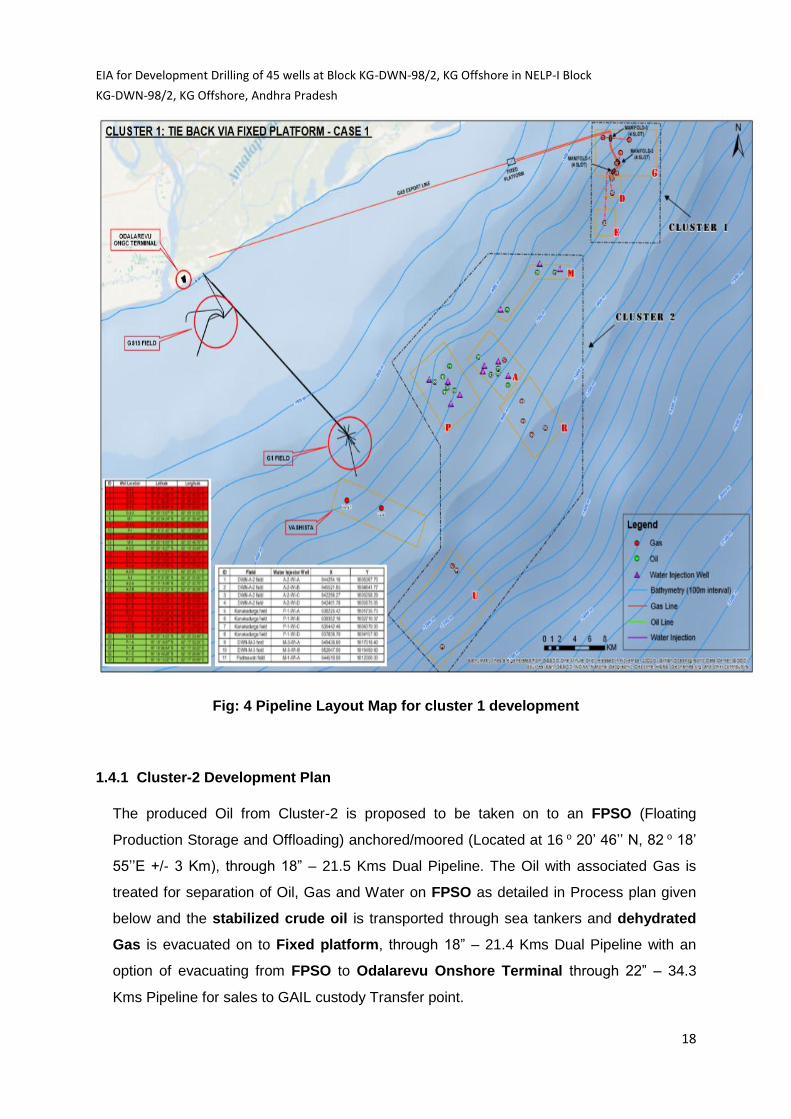
Fig: 4 Pipeline Layout Map for cluster 1 development
1.4.1 Cluster-2 Development Plan
The produced Oil from Cluster-2 is proposed to be taken on to an FPSO (Floating
Production Storage and Offloading) anchored/moored (Located at 16 o 20’ 46’’ N, 82 o 18’
55’’E +/- 3 Km), through 18” – 21.5 Kms Dual Pipeline. The Oil with associated Gas is
treated for separation of Oil, Gas and Water on FPSO as detailed in Process plan given
below and the stabilized crude oil is transported through sea tankers and dehydrated
Gas is evacuated on to Fixed platform, through 18” – 21.4 Kms Dual Pipeline with an
option of evacuating from FPSO to Odalarevu Onshore Terminal through 22” – 34.3
Kms Pipeline for sales to GAIL custody Transfer point.

EIA for Development Drilling of 45 wells at Block KG-DWN-98/2, KG Offshore in NELP-I Block
KG-DWN-98/2, KG Offshore, Andhra Pradesh
19
Fig: 5 Pipeline Layout Map for cluster 2 development

EIA for Development Drilling of 45 wells at Block KG-DWN-98/2, KG Offshore in NELP-I Block
KG-DWN-98/2, KG Offshore, Andhra Pradesh
20
Integrated development scheme of Cluster-1 and Cluster-2 is illustrated in Fig: 6.
Fig: 6.Integrated development scheme of Cluster-1 and Cluster-2
1.5 On land Facilities at Odalarevu Onshore Terminal
There is an existing terminal at Odalarevu, for processing of hydrocarbons received from offshore
fields: G-1, Vasishta and S-I through the existing 10” & 14” export flow line crossing shore at
land fall point as shown in Fig:3. The 20” & 22” gas export flow lines from KG-DWN-98/2
fields will also be crossing the shore at same land fall point, passing in the same corridor
parallel to the existing 10” & 14” export flow line, where in the production from KG-DWN-
98/2 field will be processed at the facilities to be created in the existing on shore terminal.

EIA for Development Drilling of 45 wells at Block KG-DWN-98/2, KG Offshore in NELP-I Block
KG-DWN-98/2, KG Offshore, Andhra Pradesh
21
Figure 7: Odalarevu Terminal and 10” Pipeline Shore Crossing
1.6 COASTAL REGULATION ZONE
The earlier project consisting of the onshore facility and sub-sea pipeline is located in the
Coastal Regulation Zone (CRZ) as per the CRZ Notification, 2011. The project was
appraised and recommended for CRZ clearance by the Andhra Pradesh Coastal Zone
Management Authority (APCZMA) in the meeting held on 21st September 2013. Proposal
for CRZ clearance was presented in 144th meeting held on 28-30th January’2015. CRZ
Clearance was agreed to the project vide File No: 11-2/2015 –IA-III.

EIA for Development Drilling of 45 wells at Block KG-DWN-98/2, KG Offshore in NELP-I Block
KG-DWN-98/2, KG Offshore, Andhra Pradesh
22
The High Tide Line (HTL) and Low Tide Line (LTL) was demarcated for the proposed project
area by the Institute of Remote Sensing (IRS), Anna University, Chennai, which is one of the
authorized agency to do t Report for the same. The HTL-LTL map is provided in Figure 7.
The total area of proposed onshore facility is 2, 22, 577 m2 (55 acre) of which only about
2,671 m2 (1.2% of the total area) falls in the region of 200 m – 500 m from the HTL, which is
designated as CRZ III (Areas that are relatively undisturbed and those do not belong to
either CRZ-I or II, which include coastal zone in the rural areas (developed and
undeveloped) and also areas within municipal limits or in other legally designated urban
areas, which are not substantially built up).
The proposed pipeline from the proposed expansion is coming under CRZ III. As per Section
8, III (A, iii, f and B, iii) of the CRZ Notification 2011, “facilities for regasification of liquefied
natural gas” is permissible in CRZ III.
The existing pipe lines carrying hydrocarbons from G-1& Vasishta and S-I offshore fields
passing from land fall points to the existing Odalarevu onshore terminal passes through
forest land for which stage-1 clearance is being obtained vide RC. No: 6907/2012-D1, Dated
31.12.2014.
1.6 Process Description
Well Fluid will be transported to the GAIL custody transfer meter point for sales through
subsea pipelines (20” pipeline from Fixed Platform and 22” Pipe line from FPSO) up to
Terminal for proposed facilities
Existing Terminal

EIA for Development Drilling of 45 wells at Block KG-DWN-98/2, KG Offshore in NELP-I Block
KG-DWN-98/2, KG Offshore, Andhra Pradesh
23
landfall point and from landfall to MEG (Methyl Ethylene Glycol) recovery plant located in the
existing Vashishta & S1 Plant at Odalarevu Onshore plant.
Brief description of the processing facilities as well as utilities at Fixed Offshore Platform
(for processing of Gas) and FPSO (for processing of Oil and Associated Gas):
1. Receiver Facilities: Production fluid will be received at fixed offshore platform
(Free Gas from Cluster-1 fields)/FPSO (Oil with associated Gas from Cluster-2 (a) &
(b) fields). The produced hydrocarbon fluids are passed through Vertical separator
for first stage of separation. The vertical separator will separate the well fluid in to HC
gas and water streams while flowing through the separator. The separated gas will
be further treated, compressed and conditioned to meet desired sales gas
specifications. Separated produced water will flow into the treatment facilities for
treatment and disposal. Vertical 2-phase separator is installed to separate full well
stream into gas and liquid phase. The production separator operates at pressure of
30 kg/cm2 (Early Life) and 15 kg/cm2 (Late Life)
Gas Compression System: Produced gas is compressed from 30 k/cm2 to 150
k/cm2 on offshore facilities before sending back to onshore via export pipelines (22”
or 20”) for metering and sale through GAIL custody transfer meter
Booster Compression System: At late field life, booster compression system is
required to boost the pressure from 15 kg/cm2 to 30 kg/cm2 for offshore facilities
Chemical Injection Skids-Wellhead: Chemical Injection skids like PPD (Pour Point
Depressant), CI (Corrosion Inhibitor) and Scale inhibitor
Flare System/Flare Stacks: Flare stacks are primarily used for burning off
flammable gas released by pressure relief valves during unplanned over-pressuring
of plant equipment. During total plant or partial plant start-ups and shutdowns, flare
stacks are also often used for the planned combustion of gases over relatively short
periods.
Instrument Air Package: To Supply IA (Instrumentation Air) to Flare and Process
consumption
2. Gas Treatment, Compression, Dehydration: Separated gas from separator will
receive further treatment in inlet scrubbers for removal of 99.9% liquid and solid
particles over 10 microns. This will ensure that small particles of liquid do not go into

EIA for Development Drilling of 45 wells at Block KG-DWN-98/2, KG Offshore in NELP-I Block
KG-DWN-98/2, KG Offshore, Andhra Pradesh
24
the compressors. All compressor units will be equipped with auxiliary systems such
as inter-stage and outlet gas coolers and inlet, inter-stage and outlet liquid
separators. Compressed stream from the gas compressors shall be considered for
dehydration. The Gas dehydration package shall be designed to dehydrate the gas
down to the water level of 7 lb/mmscf. Finally, the conditioned gas will be transported
to onshore for metering and sale through GAIL custody transfer meter.
3. Produced Water Treatment: Produced water separated from the separator will be
treated in water treating package and stored in to produced water tank which will be
further pumped to the disposal wells through existing transfer lines. Since MEG
(Mono-Ethylene-Glycol) will be injected as hydrate inhibitor at upstream, produced
water treating facilities shall include necessary arrangement for MEG recovery.
Recovered MEG along with produced water shall be pumped to onshore facility for
regeneration and recycled back to the chemical injection package for injection.
4. Utilities / Off-sites & Miscellaneous Systems: Utilities as needed to be generated
within the terminal. Following utility systems are envisaged for the terminal:
a. Plant and Instrument Air System
b. Nitrogen System
c. Water System
d. Circulating Hot Oil System
e. Fuel Gas System
f. Power Generation System
g. Chemical Injection system
h. Diesel system
i. Flare and Drain System
j. Fire Water System
5. Gas Dehydration Package: TEG (Tri-Ethylene-Glycol) based vendor designed &
supplied gas dehydration package to be guaranteed for water content in outlet gas as
7 lb/MMSCF.
6. Produced Water Treating: The produced water (PW) treating package shall perform
PW degassing, HC condensate separation, filtration and MEG recovery.
7. Air & Nitrogen System: Compressed dry air will be used for instrumentation. The
system shall be designed to suppress the water dew point to -40°C at atmospheric
pressure. Instrument air receiver shall be designed for hold-up time of 30 minutes

EIA for Development Drilling of 45 wells at Block KG-DWN-98/2, KG Offshore in NELP-I Block
KG-DWN-98/2, KG Offshore, Andhra Pradesh
25
minimum. Separate utility air receiver shall be provided for service air requirements.
Nitrogen will be used for inert gas blanketing and miscellaneous purging purposes.
Nitrogen generator shall be membrane type producing 98.5% (by vol.) pure nitrogen.
8. Circulating Hot Oil System: Circulating hot oil system shall be designed to suffice
heating needs at gas dehydration and TEG regeneration package. Hot oil heating will
be through waste heat recovery system at power generator exhaust.
9. Diesel: Diesel storage and transfer pumps shall be provided to cater diesel needs at
the terminal. Diesel tanks to be provided for fire water pumps and emergency DG
set.
10. Power: In-house gas based power generation to be considered for total power needs
at the terminal.
11. Flare: Flare is used to dispose of waste gases and relief gases resulting from
treatment process upsets. The process involved will dictate flare system design
requirements. For disposal of blow down gases during a plant emergency shutdown,
a dedicated flare system will normally be needed to handle the large quantity
and varied composition of the gas.
1.6.1 Oil Processing System Functionality:
Crude Stabilization System: Crude oil is stabilized in 2-stage stabilization system
Stabilization Heater: Heating the oil to achieve TVP of 10 psia @1000C
Vapour Recovery System: 3-stage Vapour Recovery Unit (VRU) is applied to compressed
the associated gas from crude stabilization from 0.5 kg/cm2 to 30 kg/cm2 before sending the
recovered gas stream into Export Gas Compression system
Gas Lift Compression System (Late Field Life): 80 MMscfd (Million Standard Cubic Feet
per Day) gas lift is compressed from 150 kg/cm2 to 260 kg/cm2
Produced Water Treatment Package: Consist of hydro-cyclone and degasser for achieving
the OIW spec of 40ppm
EIA for Development Drilling of 45 wells at Block KG-DWN-98/2, KG Offshore in NELP-I Block
KG-DWN-98/2, KG Offshore, Andhra Pradesh
26
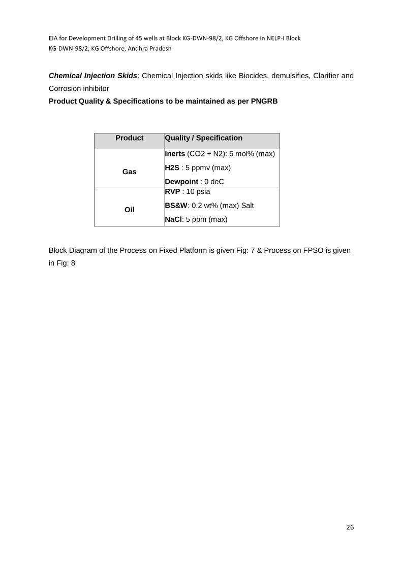
Chemical Injection Skids: Chemical Injection skids like Biocides, demulsifies, Clarifier and
Corrosion inhibitor
Product Quality & Specifications to be maintained as per PNGRB
Product Quality / Specification
Gas
Inerts (CO2 + N2): 5 mol% (max)
H2S : 5 ppmv (max)
Dewpoint : 0 deC
Oil
RVP : 10 psia
BS&W: 0.2 wt% (max) Salt
NaCl: 5 ppm (max)
Block Diagram of the Process on Fixed Platform is given Fig: 7 & Process on FPSO is given
in Fig: 8

EIA for Development Drilling of 45 wells at Block KG-DWN-98/2, KG Offshore in NELP-I Block
KG-DWN-98/2, KG Offshore, Andhra Pradesh
27
Fig: 7 Block Diagram of the Process on Fixed Platform

EIA for Development Drilling of 45 wells at Block KG-DWN-98/2, KG Offshore in NELP-I Block
KG-DWN-98/2, KG Offshore, Andhra Pradesh
28
Fig: 8 Block Diagram of the Process on FPSO
EIA for Development Drilling of 45 wells at Block KG-DWN-98/2, KG Offshore in NELP-I Block
KG-DWN-98/2, KG Offshore, Andhra Pradesh
29
1.7 SUBSEA PIPELINES AND EQUIPMENT
1.7.1 Pipeline and Subsea Structures
The proposed project of KG-DWN-98/2 development comprises of 31 production wells and
10 water injection wells as detailed elsewhere in the document. Production fluids shall be
evacuated to the offshore processing facilities at the offshore platform and FPSO (Floating
Production, Storage and Offloading) facilities via dual 20 inch nominal bore (NB) production
pipelines manifold and the offshore processing facilities. The infield pipelines that tie-in the
wellheads to the manifolds shall be 8 inch pipelines. The Gas export pipelines to the onland
facilities for custody transfer shall be 20 inch pipelines one each from the offshore platform
and 22 inch from the FPSO.
The approximate length of the pipeline between the offshore platform and onshore custody
transfer point is 35 km and from the FPSO to the onshore custody transfer point will be 35
Km. The onshore section of pipeline between landfall and the terminal ESDVs is
approximately 4km. The network of pipelines between various subsea components and
wellheads to the offshore processing facilities is as shown in the figures. The landfall section
of pipe has higher integrity requirements and therefore higher wall thickness. Constant bore
has been maintained through the pipeline to allow pigging.
1.7.2 Subsea Structures and their Arrangement
The major subsea equipment/facilities, other than the pipeline include: Subsea tees, On tree
flow meters (multiphase), Subsea Controls (comprising of Subsea Distribution Unit (SDU’s),
Umbilical Termination Assemblies (UTA’s), HDU, Master Control System (MCS)/Electric
Power Unit (EPU) and Topside Umbilical Termination Unit (TUTU), Main and infield umbilical
and Diver less connectors
Inline tees shall be installed as part of the pipeline, at the all the well locations and shall
facilitate tie-in of the wells. Spare inline tees and slots in the various manifolds will be
provided to allow future expansion. The tie-back distance between landfall and the FPSO
location is approximately 30km. The tie-back distance from landfall point to offshore platform
approximately 30 km. There is also an approximately 4km onshore section of pipeline
between landfall and ESDVs.
All tees and PLEM shall allow for the production fluids from the associated well to be
diverted to either, or both of the dual pipelines. All infield jumper spools between PLETs,
PLEM, tees and wells shall be rigid 6 inch pipe. All connections shall be via vertical
diverless connectors.

EIA for Development Drilling of 45 wells at Block KG-DWN-98/2, KG Offshore in NELP-I Block
KG-DWN-98/2, KG Offshore, Andhra Pradesh
30
Master control system (MCS), Hydraulic Power Units (HPU), Electrical Power Unit
(EPU) and Chemical Injection System shall be provided at the FPSO and offshore
platform. These components shall be connected to the subsea system via a static
umbilical, which run along with the pipelines and terminated in an Umbilical Termination
Distribution Assembly (UTDA) at Vashishta well cluster.
Infield umbilicals (each approximately 3km) shall connect the Xmas trees.
All subsea umbilical and flying lead connections will be driverless make-up.
1.7.3 Design Details of Production pipelines
All the well fluid from the Gas field shall will be produced via 20 inch and 22 inch NB
pipelines routed from offshore platform and FPSO to terminal respectively.
Pipeline Design Conditions- The pipelines shall be designed according the following
parameters:
Parameter KG - DWN - 98/2
Water Depth Max (m) 1500
Water Depth Min (m) 0
Pipeline Length (m) 28,000 to 35,000
Maximum Design Temperature
( C)
65
Minimum Design Temperature ( C) -75
Design Pressure (barg) 255
Pre-trenching; burial along with concrete weight coating for protection of pipeline
shall be done as follows:
- 2.5 metres burial for the onshore section.
- 2.5 metres burial and 50mm concrete coating up to 27 metres water depth. This
will be approximately up to two thirds of the way along the first leg of the
pipeline.
- 1.0 metre burial and 50mm concrete coating up to 79 metres water depth.

EIA for Development Drilling of 45 wells at Block KG-DWN-98/2, KG Offshore in NELP-I Block
KG-DWN-98/2, KG Offshore, Andhra Pradesh
31
- 30mm concrete coating up to 200 metres water depth.
- Three layer polypropylene (3LPP) coating and surfaced laid for the remainder
of the development.
The pipelines shall be protected from external corrosion by a combination of
coatings and cathodic protection via bracelet anodes, fitted along the length of the
pipeline. A 3LPP/ 3LPE is the recommended anti-corrosion coating for the gas
production pipeline.
The corrosion inhibitor selected shall achieve a minimum of 95% inhibitor
efficiency for the basic process condition of KG-DWN-98/2 produced fluids and
compatibility with MEG injection shall be ensured.
The pipelines shall be designed to permit the use of pigs, with due consideration
to be taken of transitions in bore between the flow line, pipelines and manifold
piping. Any tees within the main production flow line system shall be piggable with
the inclusion of pigging bars and any bends shall have a minimum radius of 5D.
1.8 Pipeline Material Details
Item Material
Gas
Production
Flowline
Linepipe- Seamless carbon steel line pipe API 5L X65 with 3.0
mm corrosion allowance.
Tie-in spools Linepipe/Bends- UNS S32760 or BETTER super dulex with 1.0
mm corrosion allowance.
PLEM Piping System- Seamless carbon steel line pipe API 5L X65 with
6.0 mm corrosion allowance or corrosion resistance alloy
(duplex/super duplex stainless steel) if any uncertainties over
inhibitor efficiency in the PLEM System.
PLET Piping- Seamless carbon steel line pipe API 5L X65 with 6.0 mm
corrosion allowance or corrosion resistance alloy (CRA)
(duplex/super duplex stainless steel) if any uncertainties over
inhibitor efficiency in the PLET System.
EIA for Development Drilling of 45 wells at Block KG-DWN-98/2, KG Offshore in NELP-I Block
KG-DWN-98/2, KG Offshore, Andhra Pradesh
32
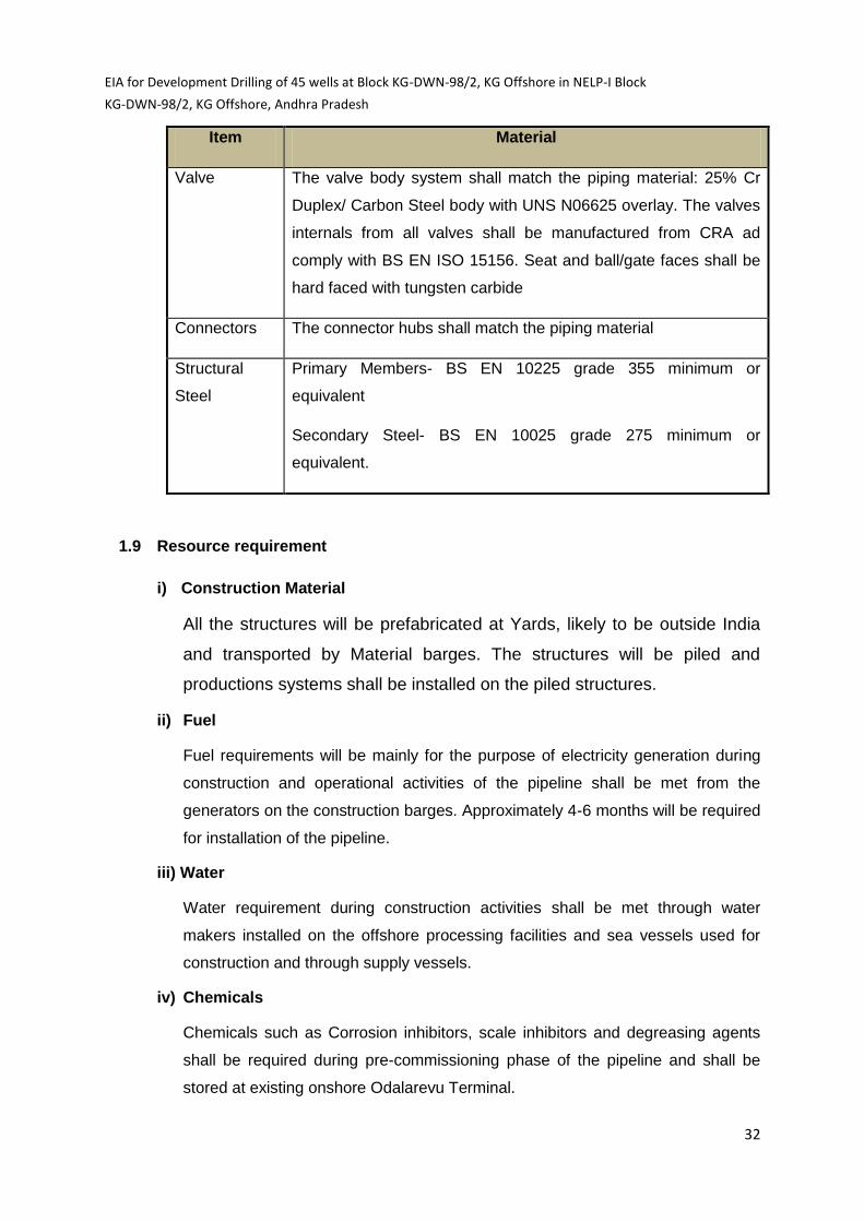
Item Material
Valve The valve body system shall match the piping material: 25% Cr
Duplex/ Carbon Steel body with UNS N06625 overlay. The valves
internals from all valves shall be manufactured from CRA ad
comply with BS EN ISO 15156. Seat and ball/gate faces shall be
hard faced with tungsten carbide
Connectors The connector hubs shall match the piping material
Structural
Steel
Primary Members- BS EN 10225 grade 355 minimum or
equivalent
Secondary Steel- BS EN 10025 grade 275 minimum or
equivalent.
1.9 Resource requirement
i) Construction Material
All the structures will be prefabricated at Yards, likely to be outside India
and transported by Material barges. The structures will be piled and
productions systems shall be installed on the piled structures.
ii) Fuel
Fuel requirements will be mainly for the purpose of electricity generation during
construction and operational activities of the pipeline shall be met from the
generators on the construction barges. Approximately 4-6 months will be required
for installation of the pipeline.
iii) Water
Water requirement during construction activities shall be met through water
makers installed on the offshore processing facilities and sea vessels used for
construction and through supply vessels.
iv) Chemicals
Chemicals such as Corrosion inhibitors, scale inhibitors and degreasing agents
shall be required during pre-commissioning phase of the pipeline and shall be
stored at existing onshore Odalarevu Terminal.

EIA for Development Drilling of 45 wells at Block KG-DWN-98/2, KG Offshore in NELP-I Block
KG-DWN-98/2, KG Offshore, Andhra Pradesh
33
1.10 Noise, Air Emissions, Effluents, and Solid Waste Generation
i) Noise
Noise is likely to be generated from the operation of generator sets, construction
machinery, earthing equipment etc during construction and installation of onshore
and offshore pipeline. Underwater sound is likely to be generated due to usage of
equipments (such as flowlines, subsea valves etc) during pipeline installation.
Transportation activities may also contribute to onshore and offshore noise levels.
ii) Air
Emission of air pollutants is likely to occur due to usage of construction vehicles
and equipment during construction, commissioning and operation of the
pipelines.
iii) Effluent and Solid Waste
Water generated from hydraulic testing of pipelines shall be reused for
multiple tests. In case of discharged into sea, discharge of water shall be
ensured at a suitable location to minimise adverse impacts.
Sewage- Sewage generated shall be treated in the Effluent Treatment Plant
(ETP). The treated effluent after treating to the desired levels shall be
discharged into sea.
Construction waste- Solid waste consisting of recyclable waste and non-
recyclable generated from construction activities, shall be segregated in
appropriated bins and will be disposed off to approved contractors for their
final disposal.
Solid waste including domestic waste (from kitchen, gallery, laundries etc),
combustible and recyclable waste generated shall be collected, segregated
and stored in specified containers and shall be transferred to authorized
contractors for its disposal.
Hazardous wastes such as waste lube/system oil from machinery, used oil
from D.G set (in case of operation) are likely to be generated. The waste shall
be handled as per Hazardous Wastes (Management, Handling and Trans-
boundary Movement) Rules, 2008. The waste will be carefully stored in drums
and transported to MoEF approved recyclers for its final disposal. All
precautions will be taken to avoid spillage from the storage.

EIA for Development Drilling of 45 wells at Block KG-DWN-98/2, KG Offshore in NELP-I Block
KG-DWN-98/2, KG Offshore, Andhra Pradesh
34
1.10.1 Field wise Hydrocarbon Reserve Breakup:
Free Gas Volume Estimate:
Fields U1 U3 A1 R1
(Annapurna)
D1 E1 UD
(SDA)
Total
(BCM)**
Gas Production
(2018-2034) in BCM**
9.32 7.27 6.21 15.26 10.39 2.88 --
GIIP* 12.38 9.44 9.166 21 13.95 3.64 80.33 149.9
*Gas Initial In-Place **Billion Cubic Meter
Oil Volume Estimate:
Discovery/
Find
Padmavathi
(M1)
Kanakadurga
(G2P1)
G-2-2-A A-2 M-3 Total
(OIIP) Oil Production (2019-2031) in MMM3
1.79 7.08 0.78 13.5 3.65 ---N/A---
OIIP*
in MMM3
7.49 23.13 4.7 55.819 15.25 106.389
* Oil Initial In Place
1.11 Geological setting
The NELP block KG-DWN-98/2 falls in the offshore part of the Krishna-Godavari Basin (KG
Basin). Krishna-Godavari (KG) Basin, a peri-cratonic rift basin along the East Coast of India,
is located between 15 to 17.50 N and 80 to 89.50 E. It covers an area of 41,000 Km2 both
onshore and offshore and includes the deltas of Krishna and Godavari rivers (Fig 1.1). The
basin comprises of the sediments ranging in age from Lower Permian to Recent. The on
land part of the basin is under alluvial cover. However, Permo-Triassic, Late Jurassic-

EIA for Development Drilling of 45 wells at Block KG-DWN-98/2, KG Offshore in NELP-I Block
KG-DWN-98/2, KG Offshore, Andhra Pradesh
35
Cretaceous and Tertiary rocks outcrop along the western margin of the basin. The basement
is of Achaean and Proterozoic rocks of the Eastern Ghats.
The basin evolution shows remarkable correlation with various tectonic episodes of opening
of East Coast of India. Four stages of tectono-stratigraphic evolution represented by four
major units such as: early rift, rift, early thermal subsidence, and late thermal subsidence.
The subsurface information obtained so far through drilling has indicated that mixed sand-
mud system may be used to interpret the depositional process in the deep water KG
offshore basin.
The area where the block KG-DWN-98/2 is located, the stratigraphy consists of slope
depositional systems and deep water depositional systems. The Pliocene section is
generally clay dominated with few deep water channel and fan deposits. Miocene to Eocene
consists of deep water clays and sand deposits in the form of basin floor fans and channels.
These form exploration targets over basement highs.
1.12 Legal and other requirements
ONGC activities will conform to all National and International legislations, regulations,
conventions, etc., relating to aspects of hydrocarbon operations in India. The project shall
abide by the Oil Industry Safety Directorate (OISD) guidelines and standards.
Recognizing the need of environmental safety, operator has established an HSE Policy
towards environmental protection. A list of applicable Acts and Rules is described in Table
1.4.
Table: 1.4 Applicable Acts and Guidelines
Issues Applicable Legislation
Hazardous
Substances &
Wastes
1) The Environment (Protection) Act, 1986 and Rules there under -
a) Hazardous Wastes (Management, Handling and Trans-boundary
Movement) Rules, 2008 and amendments thereafter;
b) Guidelines for disposal of solid wastes by Oil Drilling and Gas
Extraction industry as notified, vide notification dated GSR 546
(E) August 2005
2) The Public Liability Insurance Act, 1991 and Rules 1991
Water 3) The Environment Protection Act, 1986 - Standards for liquid
discharge by Oil Drilling and Gas Extraction industry as notified
vide notification dated GSR 176 (E) April 1996 and subsequent
amendments .
Safety and 4) Oil Mines Regulations, 1984.

EIA for Development Drilling of 45 wells at Block KG-DWN-98/2, KG Offshore in NELP-I Block
KG-DWN-98/2, KG Offshore, Andhra Pradesh
36
Issues Applicable Legislation
Protection
against Pollution
of Environment
5) Oil Field (Regulation and Development) Act 1948 and The
Petroleum & Natural Gas Rules, 1959 and amendments thereafter.
6) Coast Guard Act, 1950 for combating marine pollution and security
of the maritime zones of India-NOSDCP
7) Territorial water, continental shelf, exclusive economic zone and
other maritime zones act, 1976 for certain matters relating to the
territorial water, continental shelf, exclusive economic zone and
other maritime zones of India.
8) MARPOL Convention, 1973/78 for preventing and minimizing
pollution from ships-both accidental pollution and that from routine
operations.
9) International convention for the Safety of Life at Sea (SOLAS),
1973, as amended for safety of vessels
1.13 Project benefits
It is expected that the proposed development drilling and subsequent development of
fields would lead to production of 51.33 BCM (Billion Cubic Meters) of Gas over a period
of 16 years and 26.71 MMM3 (Million Cubic Meters) of Oil over a period of 12 years, in
the present scenario of growing demand of Oil and Gas in the country. Floating
Production Storage and Offloading (FPSO), Offshore Fixed Platform, Subsea Production
Systems (SPS) and Subsea Pipelines connecting to Landfall point to existing onshore
terminal for custody transfer to GAIL would further enhance the energy security.
This will help in moving toward achieving self-sufficiency in energy sector and also saving a
huge foreign exchange reserves of the country. This will also help in propelling the growth of
local Industry thus improving the local population wellbeing and significantly contributing to
the economy of society by creating indirect employment.
EIA for Development Drilling of 45 wells at Block KG-DWN-98/2, KG Offshore in NELP-I Block
KG-DWN-98/2, KG Offshore, Andhra Pradesh
37
CHAPTER-2
Drilling Technology
2.1 Drilling Process
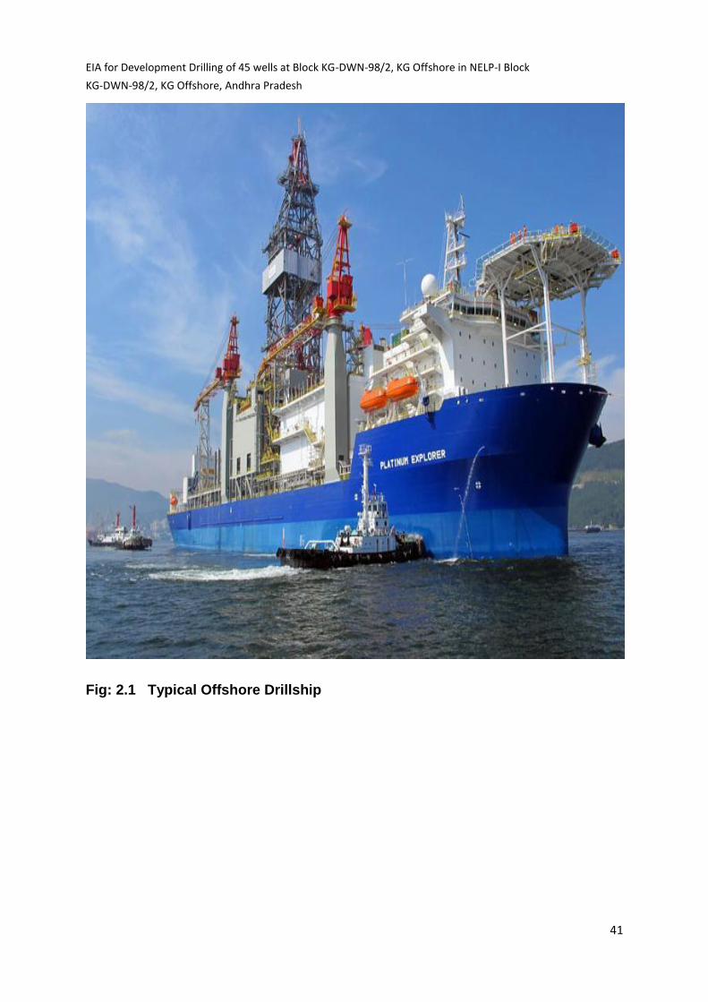
Drilling in deep waters is done by using drill ships which is a self-propelled,
dynamically Positioned vessel (Fig 2.1) with drilling facilities on board. The well is
drilled using rotary drilling system that consists of a derrick mounted on the drill floor,
at the top of which is mounted a crown block and a hoisting block with a hook. From
the swivel is suspended a Kelly stem which passes through a square or hexagonal
Kelly bush which fits into the rotary table. The rotary table receives the power to
drive it from an electric motor. The electric motor rotates the rotary table which
passes through the Kelly bush and the rotations are transmitted to the bit. As the
drilling progresses, the drill pipe in singles is added to continue the drilling process.
At the end of the bit life, the drill pipes are pulled out in stands and stacked on the
derrick platform. After changing the bit, the drill string is run back into the hole and
further drilling is continued. This process continues till the target depth is reached.
Initially well is drilled with water based mud systems. Synthetic Oil Based Mud
(SOBM) is used as drilling fluid in the target sections(12-1/4” and 8-1/2” hole). The
quantity of drill cuttings generated is around 300-500 m3 and quantity of wastewater
will be around 20 m3/day. The rig will be provided with solids handling system
comprising Shale shakers, De-sander and De-silter.
transports them to the surface through the annular space between the drill string and
the hole. The mud not only transports crushed rock cuttings from the bottom of the
hole, but it also cools the bit as it gets heated due to friction with formation while
rotating. The mud also helps in balancing subsurface formation pressures, and
diminishes the possibility of crumbling or caving of the well bore.by forming a cake
on the walls of the well.

EIA for Development Drilling of 45 wells at Block KG-DWN-98/2, KG Offshore in NELP-I Block
KG-DWN-98/2, KG Offshore, Andhra Pradesh
38
Approximate quantities of cuttings
Table: 2.1 (a) At water depth of 600 m, Drilling Depth: 4500 m
Hole size(in) 26” 171/2” 12¼” 8½” Total vol. of
cuttings (M3)
Depth (m) 600-700 700-1600 1600-3000 3000-
4500
--
Cuttings(m³) 35 105 110 55 305 +20%
caving
Approx. ~ 370
M3
Recipient
environment
Sea
Bed
Sea Bed Sea Sea
Table: 2.1 (b) At water depth of 2500 m Drilling depth 6000 m
Hole size(in) 26” 171/2” 12¼” 8½” Total vol. of cuttings
(M3)
Depth (m) 2500-
2600
2600-
3500
3500-
5000
5000-
6000
--
Cuttings(m³) 35 105 115 38 293 +20% caving
Approx. ~ 350 M3
Recipient
environment
Sea
Bed
Sea Bed Sea Sea
Cuttings generated due to the crushing action of the bit, are removed by flushing the
well with duplex/triplex mud pumps. The mud from the pump discharge through the
rotary hose connected to stationary part of the swivel, the drill string and bit nozzles
(Fig 2.2). The mud coming out of the bit nozzles lift the cuttings up hole and At the
surface, the mud coming out from well along with the cuttings falls in a trough,
passes through the solids control equipment i.e. shale shaker, de-sander and de-
silter. These equipment remove the solids of different sizes which get mixed with the
mud during the course of drilling. The cleaned mud flows back to the suction tanks to
be re-circulated into the well. The drilling mud/fluid circulation is thus a continuous

EIA for Development Drilling of 45 wells at Block KG-DWN-98/2, KG Offshore in NELP-I Block
KG-DWN-98/2, KG Offshore, Andhra Pradesh
39
cyclic operation. The mud is continuously tested for its properties (density, viscosity,
yield point, water loss, pH value etc). to ensure that the drilling operations can be
sustained without any down hole complications. Sufficient hydrostatic head (mud
density) is maintained to prevent any influx of formation fluid.
2.2 General Requirements of Drilling
Drilling is a temporary activity which will continue for about 45-60 days for a well in
the block. The rig is self-contained for all routine jobs. Once the drilling operations
are completed, if sufficient indications of hydrocarbons are observed while drilling
and in logs recorded, the well will be tested by straddle packer Drill Stem Testing
(DST), which normally takes one day. If the well is found to be successful &
hydrocarbon bearing, it is sealed off for future development. Exploratory drilling
programme requires the following common facilities:
2.2.1 Drilling muds
Drilling of wells requires specially formulated drilling fluids, to give mud weight
(density), fluidity and filter cake characteristics. The drilling muds have several
functions like lubrication and cooling of the drill bit, balancing subsurface formation,
bringing out the drill cuttings from the well bore, thixotropic property to hold cuttings
during non-operations, formation of thin cake to prevent liquid loss along well bore
etc. Several additives are mixed into the mud system to give the required properties.
Water based mud is initially used. Subsequently Synthetic Oil Base (SOBM) mud is
used in the target sections to avoid hole complications associated with the geological
formations, temperature and associated hole stability problems. SOBM provides flat
rheology profile in temperature range of 40o -250o F, which better manages the
Effective Circulating Density (ECD) and hydraulics, thereby allowing good hole
cleaning. The essential constituents of Synthetic Oil Base Mud are base oil, lime and
CaCl2, brine, along with Emulsifier and Wetting agents. Viscosifier used to control
fluid loss.
The development of deep water and ultra deep water operations brings new and
more complex technical challenges due to extreme pressures and temperature

EIA for Development Drilling of 45 wells at Block KG-DWN-98/2, KG Offshore in NELP-I Block
KG-DWN-98/2, KG Offshore, Andhra Pradesh
40
encountered at these depths (Temperatures of up to 2o C and pressures up to 400
bars are common at the mud line).
EIA for Development Drilling of 45 wells at Block KG-DWN-98/2, KG Offshore in NELP-I Block
KG-DWN-98/2, KG Offshore, Andhra Pradesh
41
Fig: 2.1 Typical Offshore Drillship

EIA for Development Drilling of 45 wells at Block KG-DWN-98/2, KG Offshore in NELP-I Block
KG-DWN-98/2, KG Offshore, Andhra Pradesh
42
Fig: 2.2 Mud circulation system
The drilling fluid while flowing through well and riser length will experience
temperatures ranging from 0oC to 150o C and must keep its properties for this whole
range. The mud rheological properties will strongly depend on temperature and
pressure variation and these variation will be different for different mud formulations.
These temperature and pressure ranges are also favourable conditions for the
formation of gas hydrates in drilling mud. Hydrates are solid structures formed from
water and gas. Water content in drilling mud form under certain temperature and
pressure conditions, a solid structure with gas molecules. Hydrate formation requires
four factors to be present:

EIA for Development Drilling of 45 wells at Block KG-DWN-98/2, KG Offshore in NELP-I Block
KG-DWN-98/2, KG Offshore, Andhra Pradesh
43
Gas ,
Temperature lower than the calculated freezing point,
Pressure (hydrostatic at BOP),
Time. Formations of these solid gas hydrates is likely to plug, kill and choke lines as well
as annular spaces, and may cause interruption of drilling operation and even
destruction of rig equipment. Use of thermodynamic inhibitor additives (mainly salt
and glycol additives), displaces the equilibrium point of hydrate formation.
In this block, water depth ranges from 320-2840 m. Drilling in these extreme water
depths may require the use of riser less drilling technique which is not constrained by
the length limitations of a riser system. Riser less mud recovery (RMR) provides a
dual gradient drilling setup of the well while capturing the drilling fluids and returning
it to the drill ship. The term dual gradient implies two hydrostatic gradients-
The sea water gradient that begins at sea surface
The drilling mud gradient that begins at the sea floor
Conventional drilling has only one pressure gradient for both sea water and mud
that originates at sea surface. Because dual gradient drilling has much less
hydrostatic head associated with the drilling mud in the borehole, drilling fluids can
be properly weighted allowing drilling to be more easily within the formation pore
pressure and fracture pressure there by avoiding well bore instability.
Initially a 12¼” investigative hole will be drilled to check any shallow water flows. Any
flow will be killed with Heavy Mud. The 36” conductor casing will be jetted up to 90m
below mud line and further drilling with 26” bit will be carried out with Pump and
Dump method after pumping High viscous Sweep displaced with Inhibitive Glycol
mud. Casing 20” will be lowered and cemented. Low seabed temperatures and
water depths may lead to the formation of gas hydrates inside the BOP. In principle,
the freezing point is suppressed by using the salts up to the density limits, and then
with Mono-ethylene glycol (MEG) and Poly-Alkylene Glycol (PAG). Achievement of
adequate cuttings transport in the long riser section at the relatively low annular
velocity is the critical factor. The mud’s carrying capacity must be maintained. And

EIA for Development Drilling of 45 wells at Block KG-DWN-98/2, KG Offshore in NELP-I Block
KG-DWN-98/2, KG Offshore, Andhra Pradesh
44
the riser flow rate should be boosted wherever possible. Good shear thinning
characteristics are therefore required to minimize the PV. The ECD should be
closely monitored to avoid exceeding the expected low fracture gradients.
GLYDRIL is a water based polymer fluid, which consists of the following chemicals:
Sodium and/or Potassium salts.
GLYDRIL MC – Mid Salinity range clouding Poly alkylene Glycol.
PAC-R/UL – (Poly anionic Cellulose) – Primary filtration control.
POLYPLUS RD (PHPA) – Provide solids encapsulation, well bore stability
and filtration control. IDCAP-D, a low molecular weight poly-acyrlamide
can be substituted for Polyplus-RD.
DUOVIS (Xanthan Gum) – Provide low-end rheology.
KLASTOP – Polyamine for supplemental inhibition.
For new mud additions, seawater can be used, properly treated with Bactericide and
softened with Soda Ash and Caustic Soda to remove the unwanted divalent ions,
Ca++ and Mg++. However later, if chloride levels have to be controlled, drill water
treated in the same way should be used. The potassium ions will exchange with
sodium ions on the clay platelets. Subsequent additions of KCl will have the effect of
increasing the chlorides, mud weight and hydrate suppression.
Table:2.2 Typical chemical requirement for drilling the deep water well.
PRODUCT Concentration(lb) Purpose
ASPHASOL 5.0 Inhibitor
BARITE As required Weighting Agent
BENTONITE As required Clay
CALCIUM
CARBONATE
As required Loss control Additive
CAUSTIC
SODA
0.5 pH
CITRIC ACID As required pH control
CONQUOR
303A
As required Corrosion Inhibitor
KLASTOP 10.5 Emulsifier
Duovis 1.5 Viscosifier

EIA for Development Drilling of 45 wells at Block KG-DWN-98/2, KG Offshore in NELP-I Block
KG-DWN-98/2, KG Offshore, Andhra Pradesh
45
Glydrill-MC 17.5 Hydrate inhibitor
Guar GUM As required viscosifier
KCL 23.5 Inhibitor
MEG 28.0 Hydrate inhibitor
MI-cide 0.3 Biocide
Nacl 56.0 Hydrate inhibitor
PacUL 3.5 Fluid loss control
Polyplus RD 1.5 Encapsulating Polymer
In case of any Borehole problem environment friendly Low toxic Synthetic Oil Base
Mud will be used. After lowering Riser and BOP, further drilling will be resumed with
RHELIANT Synthetic Oil Base Mud up to target depth. The following chemicals are
generally be used.
Table:2.3 Composition of Synthetic Oil Base Mud
Additive Trade Name Concentration in Drilling Mud Pounds/Barrel
Emulsifier SUREMUL 6-10
Rheological Modifier
RHETHIK,RHEFLAT 0.1-0.25
Fluid Loss Additive ECOTROL 0.25-0.75
Lime -- 8.0
Calcium Chloride -- 23.6
Wetting Agent SUREWET 1.0-2.0
Base Oil EDC Diamond 60%
2.2.2 Power Generation
The drilling process requires movement of drill bit through the draw works which
require power. The power requirement of the drilling rig will be met by using the
Diesel Generator sets of 1430 kVA capacity 4 nos. with a diesel consumption of
about 8-12 Kl / day. The exhaust stacks of the DG sets are likely to vent off the
emissions at the height of approximately 30 m above mean sea level.

EIA for Development Drilling of 45 wells at Block KG-DWN-98/2, KG Offshore in NELP-I Block
KG-DWN-98/2, KG Offshore, Andhra Pradesh
46
2.2.3 Water requirements
The water requirement in a drilling rig is meant for preparation of drilling mud apart
from washings and domestic use. The water requirement for domestic and wash use
is very less. The daily water consumption will be 30 m3/d will be used. The operating
personnel in the drilling rigs will operate from on board accommodation. Sanitary
water is passed through sewage treatment plant on board and discharged to sea
after treatment and meeting the requirement of standards i.e Residual chlorine 1
ppm.
2.2.4 Solids removal
During drilling operations, approx.. 300-500 m3 of wet drill cuttings are expected to
be generated for one well depending on the depth of the well. The rock cuttings and
fragments of shale, sand and silt associated with the return drilling fluid during well
drilling will be separated using shale shakers and other solids removal equipment
like de-sander and de-silter. The recovered mud will be reused while the separated
solids will be discharged to sea after proper washing and dilution as per GSR 546(E)
2005. Residual waste mud if remained will be discharged into sea after proper
dilution as per guidelines.
2.2.5 Chemical storage
The drilling rig will have normal storage facilities for fuel oil, required chemicals and
the necessary tubular and equipment. The drilling rig have general deck storage
system. All the chemicals are clearly labelled the storage places will be clearly
marked.
The Deep water drilling requires storage of the following chemicals
Hydrate inhibitors (Mono ethylene Glycol, Poly alkene Glycol, NaCl etc)
Polymeric viscosifiers
Polymeric Fluid loss control agents
Barite(Weighting Agents)
KCl (Ionic inhibition of shales)
PHPA (Partially Hydrolysed Poly Acrylamide)

EIA for Development Drilling of 45 wells at Block KG-DWN-98/2, KG Offshore in NELP-I Block
KG-DWN-98/2, KG Offshore, Andhra Pradesh
47
Sulphonated Asphalt (Shale Stabilisers)
Caustic Soda (for pH control)
Cement additives
Completion Chemicals
The Bulk chemicals like Barite and Cement are stored in Silos. The corrosive
chemicals like Caustic Soda is kept in a separate enclosure with lock and key
available with the Mud Engineer.
The Chemical ware house is equipped with fire extinguisher, smoke detector, and
Fire alarm system. Material Safety data sheets of all the chemicals are kept at the
warehouse to be used in case of emergency. The Hydrate inhibitors are stored in
sealed drums. In the case of spillage, the remedial action is taken in line with the
MSDS. Drilling Detergent and EP lube is stored in seal tight barrels so that the
spillage of these chemicals during transit is avoided.
2.2.6 Manpower
The drilling rig will be having approx. 50-60 persons on the rig at any time.
Accommodation provided on board. The manpower operates in two shifts (12 hrs)
with continuous operations on the rig. The rig personnel operates on 14/28 days
ON/OFF duty pattern.
2.2.7 Logistics
Crew transfers to and from the drilling rig is through helicopter from
Rajahmundry/Visakhapatnam. The drilling materials, diesel and chemicals will be
transported through supply vessel from Kakinada base..
2.3 Deep water drilling Technology
Wells drilled in deep water have a different casing scheme than wells drilled in
shallow water. Fracture gradients are very low in deep water. This results in mud
weights very close to fracture gradients and requires more casing strings.
The casing-drill technique of setting the structural casing has been used in water
depths of 200-7500 feet. It eliminates the risk of losing the hole when the drilling

EIA for Development Drilling of 45 wells at Block KG-DWN-98/2, KG Offshore in NELP-I Block
KG-DWN-98/2, KG Offshore, Andhra Pradesh
48
assembly is pulled from the unconsolidated formation to run the structural pipe. The
procedure utilizes a hydraulically actuated Dyna-Drill motor and slightly under guage
bit suspended in the casing to drill/jet the structural pipe to the pre-determined depth.
The “pilot hole” is drilled/jetted by the bit with power supplied by the motor. The
weight of the casing at the bottom wedges additional formation into the hole where it
is drilled by the bit. The cuttings are carried up the annulus and ejected through ports
in the top of the running tool. The most commonly used assembly is a Dyna Drill (9-
5/8”, high-speed, low-torque) with attached 26” stabilizer blades and a 26” bit. The
low-torque motor minimizes turning of the casing string. A jet-sub allows the required
annular fluid volume to be achieved by diverting the fluid prior to its entry into the
motor.
The weight of the casing assembly applied to the formation varies from an initial 10-
20% to a maximum of 80% at the total setting depth of the casing. The controlled,
lighter weights at the start aid in keeping the casing at or near vertical, while the 80%
maximum provides a safety margin, keeping the neutral weight point below the
running tool.
As the casing penetrates the formation, the side frictional forces increase, absorbing
much of the applied weight. This friction is controlled by reciprocation (working) the
casing string until the drag (over pull) is reduced, allowing an effective rate of
penetration with the proper weight applied to the bottom.
Proper execution of these guidelines result in the least soil disturbance, which
minimizes the time for the soil to heal. The soil’s ability to “hold” must not be
seriously damaged by staying at one depth while washing.
After reaching the setting depth, the casing is allowed to “soak” or sit in a stationary
position allowing the soil that was penetrated to “heal” around the casing and regain
most of its holding capacity. The average is approximately 1-2 hours, with some
allowing 6 hours to soak. A trip is made for the drilling assembly while the casing
soaks. Some operators use a drill-ahead tool (Cam Actuated Drilling Assembly –

EIA for Development Drilling of 45 wells at Block KG-DWN-98/2, KG Offshore in NELP-I Block
KG-DWN-98/2, KG Offshore, Andhra Pradesh
49
CADA) that eliminates the need for a trip to pick up the drilling assembly to begin
drilling.
2.3.1 Permanent Guide Base and Temporary Guide Base The permanent guide-base and a
temporary guide-base are run on the
same assembly with the structural pipe.
The guide-base matches-up with the
blow-out preventers and provides a base
to hang off subsequent casing strings as the well is drilled.
2.3.2 Cam Actuated Drilling Assembly Tool (CADA)
The Cam Actuated Drilling Assembly (CADA) is run in the casing drill/jetting
assembly. It is activated by the following procedures:
1. The motion compensator is activated to support the weight of the drill pipe
running string, the jetting string, and a 10,000 lb over-pull to the CADA Tool.
2. The mud pumps are used to agitate the cuttings left inside the structural
pipe.
3. The remote operated vehicle (ROV) is positioned to assist with the process.
4. The drill pipe is rotated to the right approximately 5 turns to retract the split-
ring on the CADA Tool and unlocks the tool from the Wellhead Housing.
5. The center stem is released by applying right-hand torque in excess of
13000 ft-lbs.
6. The mud motor is picked up and tested.
7. Picking up the center stem shears the shear pins (75,000 lbs. over pull).
This shears it out of the 30” housing. Re-landing the assembly into the
housing allows the drilling process to begin.
The 26” hole is drilled below the structural pipe to a predetermined depth.
The CADA tool is then retrieved prior to running 20” casing.

EIA for Development Drilling of 45 wells at Block KG-DWN-98/2, KG Offshore in NELP-I Block
KG-DWN-98/2, KG Offshore, Andhra Pradesh
50
2.3.3 Down-Hole Equipment
A variety of equipment and tools are used to assist riser less drilling. They include
Logging While Drilling (LWD), Measurement While Drilling (MWD), Pressure
While Drilling (PWD), Mud Motors and Remote Operating Vehicles (ROV).
The LWD tool allows the operator to view a real-time log of the formation as it is
drilled. This is very important when drilling shallow hazards. The LWD tool is usually
located in the drill string about 30 feet above the bit. Therefore, information from the
tool is from the depth of the tool – not the depth of the bit. However, this information
is valuable to the operator while drilling.
The MWD tool allows the operator to monitor the angle and azimuth of the hole while
drilling and make necessary steering changes. This is important since the 20” casing
should be set in a near vertical position.
The PWD tool provides a constant read-out of the actual pressures in the hole while
drilling. PWD tools also measure the Equivalent Circulating Density (ECD) of the
fluid in the annulus. This knowledge allows the operator to avoid exceeding the
estimated formation fracture pressure. The mud must be circulating for the pulse of
the tool to be recorded at the surface. The tool is being used more often in the riser
less section, especially when shallow hazards are expected. Although the tool reads
directly, it is still not precisely on bottom. There are instances where the PWD tool
missed the pressure increase (when the pumps were shut off). Therefore, the PWD
tool can’t be totally relied on detecting a shallow flow. The R.O.V. will help when the
pump is shut off.
The typical rate of penetration for the riser less sections are 25’-50’ hour with pump
rates of 1000-1500 GPM. Higher penetration rates or lower pump rates could
overload the annulus with cuttings and result in loss circulation or ballooning
problems.

EIA for Development Drilling of 45 wells at Block KG-DWN-98/2, KG Offshore in NELP-I Block
KG-DWN-98/2, KG Offshore, Andhra Pradesh
51
The use of Mud Motors to drill the riser less sections of the hole minimizes hole
deviation and doglegs. Rotating the entire drill string at >100 rpm is not the preferred
way to drill the riser less section. With the running tools, CADA tool, etc in the drill
string, the mud motor is the most efficient way to drill the hole.
The Remote Operating Vehicle (ROV) plays a crucial role in deep water drilling especially
when when operating in the riser less section. The vehicle performs numerous functions.
One very important function is to monitor the hole to be sure the well is not flowing while a
connection or a trip is made.
2.3.4 Hole Cleaning
Back-reaming: Back-ream to the shoe after drilling the 24” or 26” open hole. After
back-reaming, a viscous sweep is pumped and the well checked for a flow before
going in the hole.
Short Trips: Short trips ensures the hole cleaning & stability. A viscous sweep is
pumped at the casing point to help clean the casing and riser of any cuttings left in
the annulus.
Sweeps: Sweeps are usually pumped on a periodic basis to help clean the hole.
1. Volume: Typically a volume of 100-200 bbls is used every 45’-200’.
2. Formulation: Freshwater with 25-30 ppb of M-I GEL and ½ ppb Lime, caustic soda
and/or soda ash. The normal procedure for preparing a sweep is to adjust the
yield point of the pre-hydrated gel slurry to >50 by adding seawater prior to
pumping it down the hole. This usually requires a 50% ± dilution with seawater.
2.3.5 Spotting fluid (Kill Mud):
Prior to pulling the pipe out of the hole to run 26” or 20” casing, the hole should be
filled with weighted mud. Usually, 1.5-2.0 times the calculated hole volume is
pumped. The extra volume brings cuttings left in the hole to the sea floor and
compensates for hole enlargement. The mud density can vary from 9.5 – 12.0 ppg,
depending on the water depth. Reduce the API fluid loss to the 10 ml –25 ml range

EIA for Development Drilling of 45 wells at Block KG-DWN-98/2, KG Offshore in NELP-I Block
KG-DWN-98/2, KG Offshore, Andhra Pradesh
52
to minimize the build-up of filter cake across the sands and improve chances of
getting the casing to bottom.
The kill mud weight must be sufficient to compensate for riser margin or hydrostatic
head pressure attributed to a column of seawater equivalent in length to riser and
airspace. One guideline suggests that the kill mud can be established by multiplying
the overburden pressure at the depth of interest by 0.85-0.88 divided by RKB-
TVD(Rig Kelly Bush-True vertical depth) times 0.052.
2.3.6 Drilling / Jetting 26” & 20” casing sections
One of the keys to drilling deep water wells successfully is setting the 20” casing in
the right place and having a good cement job. Some areas have a combination of
gas hydrate layers and/or shallow hazard zones to drill through. One option used is
to drill a pilot hole (8.5” or 12.5”) to total depth to determine the extent of the hazard
and minimize the effects of the hazard initially. The pilot hole mud system is typically
seawater with sweeps and returns to the seafloor. In some areas that have known
shallow hazards, the common practice is not to drill a pilot hole and to drill 24”, 26”
hole using seawater with sweeps with the larger bit sizes.
2.4 Deep water abandonment
The main requirements for any well abandonment programme are:
1. To leave the well in a safe down hole condition such that the well will retain
pressure integrity and there is no possibility of the well flowing when the BOP
or well head is removed.
2. To leave the seabed around the wellhead clear of drilling related debris.
2.4.1 Suspension requirements
The main requirements of the well suspension programme are:

EIA for Development Drilling of 45 wells at Block KG-DWN-98/2, KG Offshore in NELP-I Block
KG-DWN-98/2, KG Offshore, Andhra Pradesh
53
To leave the well in a safe condition down hole such that, if the well head
is accidentally damaged or removed, the well will retain pressure integrity
and there is no possibility of the well flowing.
To allow the well to be re-entered at a subsequent date and a BOP
installed without recourse to repair work. To cover this requirement, a
corrosion cap will be run to protect the well head and its sealing areas.
To ensure that any sea floor obstruction is minimized.
2.4.2 Well Abandonment on decommissioning
The following steps followed for well abandonment:-
All casing strings will be cut off a minimum of 5m below the seabed.
Plugs will be set no more than 50m below the seabed.
When cut intermediate casing, production casing, and liners are plugged,
it shall be verified by weight testing with 22klbs (10 tons), and pressure
tested to 1030 psi (70bar) above the formation strength that potential flow
paths are isolated and sealed.
There shall be no non-isolated route behind a string of casing from an
open hole section to surface. If the casing/casing overlap has not been
isolated with cement then the casing string will be cut deep and isolated in
the same manner as in step 1 of “Abandonment Only” above.
If the annular top of cement has not been identified on a log, then the top
of cement will be assumed by calculation.
Cutting or perforating of non-cemented casing must be performed under
full pressure control.
When cutting casing, the shoe strength at the previous casing shoe must
be high enough to with stand the mud weight in the hole. If it is not, then
the mud weight will have to be reduced. After retrieving the well head’s
and guide base, a ROV seabed survey (or equivalent) must be carried out
to confirm that the seabed is clear of drilling related debris with in a 70m
radius of the well head. This plug will be pressure tested to 1030psi (70
bar) over the formation leak-off pressure at the casing shoe behind the
liner.

EIA for Development Drilling of 45 wells at Block KG-DWN-98/2, KG Offshore in NELP-I Block
KG-DWN-98/2, KG Offshore, Andhra Pradesh
54
For permanent abandonment a 200m surface cement plug is required with
the top of the plug verified no more than 50 m below the sea bed
suspension only. In addition to common requirements the following apply
to well suspensions. A corrosion cap will be run and the well head filled
with hydraulic oil.
A planned inspection routine for the suspended well head must be
established.
The operator must also evaluate and document Buoy marking and
identification of the well head.
CHAPTER-3
Baseline Environmental Status
3.1 Introduction
In order to carry out an Environment Impact Study, it is necessary to delineate and
define the existing status of recipient environment in and around operational area of
the proposed project. Environment baseline study will record the existing quality of
environmental status within the area of influence before implementation of the
project. The existing baseline data is considered to adjudge the prevailing
environmental condition which are monitored, studied and described with respect to
climate and meteorology, oceanography, atmospheric conditions, offshore water
quality and marine ecology. Knowledge of the characteristics of the local chemical
and biological environment allows an understanding of the potential of the operations
to interact with the flora and fauna so that appropriate controls can be adopted to

EIA for Development Drilling of 45 wells at Block KG-DWN-98/2, KG Offshore in NELP-I Block
KG-DWN-98/2, KG Offshore, Andhra Pradesh
55
mitigate negative impacts. This data will then be analyzed in the chapter-4 entitled
“Identification, Prediction and Evaluation of Impacts.”
The Environment Appraisal Committee EAC-Industry of Ministry of Environment and
Forest after due consideration about utility of data has recommended following
parameters to study. Copy of prescribed TOR is appended at Annexure-1.
Climatology and meteorological data including wind speed, wave
currents and rainfall etc.
Baseline data collection for surface water for one season leaving the
monsoon season within 1km of each exploratory well, particularly in
respect of oil content.
Details of sensitive areas such as coral reef, marine water park,
sanctuary and any other eco sensitive areas.
Procedure for handling solid waste and
Procedure for preventing spills and spill contingency plan
The offshore block KG-DWN-98/2 is located off the eastern coast of India in the Bay
of Bengal, approximately at a distance of 28 Km in the north to 250 Km in the west
from the nearest shore. The approximate mean water depth of the block is 2085 m
(Water depth varies from 300m to maximum of 3000 m).
The baseline description includes collection of primary and secondary data through
field investigations, environmental monitoring and secondary sources viz. maps,
reports, scientific literatures, etc. The obtained data has been analysed for
identification of impacts and arrive at mitigation measures for minimizing any
environmental impact due to the project activities. The activities that are likely to be
studied for each environmental component are described in subsequent sections.
The study area is oceanic. There is no land within the 10 km study area. No eco
sensitive zones and national parks in the study area.

EIA for Development Drilling of 45 wells at Block KG-DWN-98/2, KG Offshore in NELP-I Block
KG-DWN-98/2, KG Offshore, Andhra Pradesh
56
3.2 Climate
According to the Indian Meteorological Organization (IMD), various seasons over
India are:
•Winter Season : January – February
•Pre Monsoon Season : March – May
•Southwest Monsoon Season : June -- September
•Post Monsoon Season : October -- December
In this block which is located at the distance of 28-250 km from the coast, the
northeast monsoon is from November through April as continental high pressure
system in north of the bay produces northeast winds characteristic of the winter
season (Fig 3.1). During the period June–September the rain-bearing southwest
monsoon prevails, as intense heat produces a low-pressure system over the
continent and a subsequent air flow from the ocean. North east monsoon and
cyclonic storms over the Bay of Bengal along South East coast of Peninsular India
bring heavy rainfall associated with major physical changes. From January to
October, the current is northward flowing, and the clockwise circulation pattern is
called the "East Indian Current". The Bay of Bengal monsoon moves in a northwest
direction striking the Nicobar Islands, and the Andaman Islands first, by end of May
and then the north eastern coast of India by end of June. The remainder of the year,
the counter-clockwise current is south west ward flowing, and the circulation pattern
is called the East Indian Winter Jet. September and December see very active
weather in the Bay of Bengal producing severe cyclones which affect the east coast
of India. Strong winds produce storm surges in many parts of the coast. Changes in
the frequency of tropical cyclones developing over the Arabian Sea and the Bay of
Bengal have been studied utilizing 122 years (1877-1998) data of tropical cyclone
frequency. Significant increasing trends in the cyclone frequency over the Bay of
Bengal have been observed during November and May which are main cyclone
months. During transitional months, June and September, however, the frequency
has decreased. The climate of the area is hot during summer season and the
temperature varies from 26o to 39oC at the surface, but the temperature decreases
to as low as 4oC at water depths of 1500m. The annual mean temperature variation
at standard depths is given in the Table: 3.7.

EIA for Development Drilling of 45 wells at Block KG-DWN-98/2, KG Offshore in NELP-I Block
KG-DWN-98/2, KG Offshore, Andhra Pradesh
57
3.3 Physical Environment
The block KG-DWN-98/2 is at the distance of 28 Km to 250 Km from the coast and
bathymetry varies from 320 m to 3100 m. Logistically, it is very difficult to get the
vessel for sampling at higher depths. ONGC has contacted premier national institute
INCOIS for the Meteorological data of the block. ONGC & INCOIS has shared
knowledge & data on following parameters for the Oceanographic and
Table:3.1 Resources for Oceanographic and Meteorological data
Measurement techniques
Parameter Data source/Monitored by Remarks
Bathym etry ETOPO1 data available at a
resolution of 1 arc-minute X 1
arc minute global relief model of
Earth’s surface
Land topography and
ocean bathymetry, built
from numerous global and
regional data sets has
been integrated.
Significant Wave
Height (SW H) CNES, France, (AVISO)
generated data on a daily basis
globally at a 1 deg. X 1 deg.
resolution.
Sea Surface
Currents OSCAR (Ocean Surface
Currents Analyses Real time)
monthly mean data on currents
at 0.33 deg. x 0.33 deg.
Resolution.
--
Ocean Surface
W inds Satellite based active (radar) and
passive (radiometer) microwave
sensors. ASCAT aboard
EUMETSAT METOP satellite.
--
Salinity &
Temperature The W orld Ocean Database
2009. Data available at high
resolution of 1 deg. X 1deg.
These databases include
cruise data, satellite
altimeter data as well as
moored and floating buoy
data, etc. This data is
available from the surface
to 1500m, at the "standard
oceanographic depths".

EIA for Development Drilling of 45 wells at Block KG-DWN-98/2, KG Offshore in NELP-I Block
KG-DWN-98/2, KG Offshore, Andhra Pradesh
58
Meteorology for the block area. The data for Bathymetry, Significant Wave Height,
Surface Ocean Currents, Wind speeds, Salinity and Temperature is real time data
monitored by satellites
3.3.1 Significant Wave Height
The significant wave height is obtained by analysing the shape and intensity of the
altimeter radar beam reflected from the sea surface (the radar echo). A long time
delay in the return signal indicates that waves are high and a short delay indicates
that the sea surface is calm. In the Table-3.3, the monthly average for the SWH (m)
based on daily data for the block location clearly shows that the maximum height
(around 2.0m) is observed during the southwest monsoon season (June-September)
associated with the sustained high winds during June-September, followed by the
northeast monsoon. During cyclones, associated with strong winds, very high
waves can form over the sea, even close to the coast. Since it is a critical
parameter, we have further examined the highest daily averaged value (averaged
over the block) during the year – 2010 (fig 3.5). It was seen that the SWH values
(averaged over the area) varied up to 3.5 m, associated with the Laila and JAL
cyclones.
Table:3.2 Bathymetry of the block KG-DWN-98/2.
Location Mean depth over
the region (m)
minimum depth in
the area (m)
maximum depth in
the area (m)
KG-DWN-98/2 2085 300 3100

EIA for Development Drilling of 45 wells at Block KG-DWN-98/2, KG Offshore in NELP-I Block
KG-DWN-98/2, KG Offshore, Andhra Pradesh
59
Table: 3.3 Significant Wave Height in meters ( Monthly average).
Month KG-DWN-98/2 Jan 1.0 Feb 0.4 Mar 0.7 Apr 1.1 May 1.7 Jun 2.0 Jul 1.9 Aug 1.5 Sep 1.5 Oct 1.4 Nov 1.3 Dec 1.4
Maximum 3.5
Fig: 3.1 Wave Height in the Block area.
0
0.5
1
1.5
2
2.5
3
3.5
4
KG-DWN-98/2
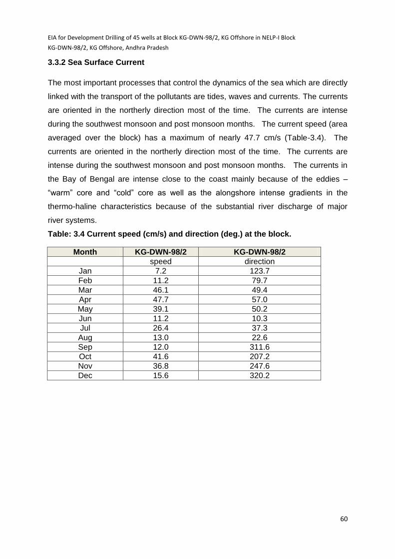
EIA for Development Drilling of 45 wells at Block KG-DWN-98/2, KG Offshore in NELP-I Block
KG-DWN-98/2, KG Offshore, Andhra Pradesh
60
3.3.2 Sea Surface Current
The most important processes that control the dynamics of the sea which are directly
linked with the transport of the pollutants are tides, waves and currents. The currents
are oriented in the northerly direction most of the time. The currents are intense
during the southwest monsoon and post monsoon months. The current speed (area
averaged over the block) has a maximum of nearly 47.7 cm/s (Table-3.4). The
currents are oriented in the northerly direction most of the time. The currents are
intense during the southwest monsoon and post monsoon months. The currents in
the Bay of Bengal are intense close to the coast mainly because of the eddies –
“warm” core and “cold” core as well as the alongshore intense gradients in the
thermo-haline characteristics because of the substantial river discharge of major
river systems.
Table: 3.4 Current speed (cm/s) and direction (deg.) at the block.
Month KG-DWN-98/2 KG-DWN-98/2
speed direction
Jan 7.2 123.7
Feb 11.2 79.7
Mar 46.1 49.4
Apr 47.7 57.0
May 39.1 50.2
Jun 11.2 10.3
Jul 26.4 37.3
Aug 13.0 22.6
Sep 12.0 311.6
Oct 41.6 207.2
Nov 36.8 247.6
Dec 15.6 320.2
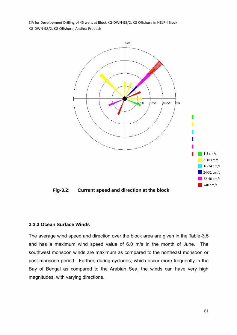
EIA for Development Drilling of 45 wells at Block KG-DWN-98/2, KG Offshore in NELP-I Block
KG-DWN-98/2, KG Offshore, Andhra Pradesh
61
Fig-3.2: Current speed and direction at the block
3.3.3 Ocean Surface Winds
The average wind speed and direction over the block area are given in the Table-3.5
and has a maximum wind speed value of 6.0 m/s in the month of June. The
southwest monsoon winds are maximum as compared to the northeast monsoon or
post monsoon period. Further, during cyclones, which occur more frequently in the
Bay of Bengal as compared to the Arabian Sea, the winds can have very high
magnitudes, with varying directions.

EIA for Development Drilling of 45 wells at Block KG-DWN-98/2, KG Offshore in NELP-I Block
KG-DWN-98/2, KG Offshore, Andhra Pradesh
62
Table:3.5 Wind speed (m/s) and direction (deg.) at the block.
Month KG-DWN-98/2 KG-DWN-98/2
speed direction
Jan 4.5 253.0
Feb 2.5 295.2
Mar 3.4 357.3
Apr 5.2 1.7
May 5.3 13.1
Jun 5.4 45.6
Jul 6.0 54.2
Aug 2.7 47.6
Sep 3.5 64.4
Oct 0.7 64.5
Nov 5.1 259.5
Dec 4.6 239.8
Maximum 14.7 216.2
Fig: 3.3 Wind rose diagram showing the Pre dominant wind directions during the year in the block.

EIA for Development Drilling of 45 wells at Block KG-DWN-98/2, KG Offshore in NELP-I Block
KG-DWN-98/2, KG Offshore, Andhra Pradesh
63
3.4 Marine Water Quality
The area of the block KG-DWN-98/2 is largely oceanic and therefore not expected to
undergo significant changes in water quality, temporarily as well as spatially.
Samples were collected keeping in view, where maximum drilling of exploratory wells
are expected to come. Therefore, most of the samples were collected in the
northern part of the block which is in close proximity to the coast where most of the
drilling prospects are located to study the environmental impacts in the area due to
proposed drilling activities (Fig 3.7). The water quality data for block is given in the
Table-8
Salinity and Temperature
The principal natural processes which lead to changes in the salinity of sea water
are those which bring about removal or addition of fresh water. In the coastal areas
of Bay of Bengal, increase in salinity is caused by evaporation and decrease in
salinity results from atmospheric precipitation and run-off from land. The surface
salinity in the open part of the Bay oscillates from 32 ppt to 34 ppt (i.e parts per
thousand) and in the coastal region it varies from 10‰ to 25‰. Figure 3.6 shows the
Surface Distribution of Salinity in the Study area and Bay of Bengal. The observed
values of the salinity are in the range of 32.9 ppt to 33.9 ppt (Table:3.8).

EIA for Development Drilling of 45 wells at Block KG-DWN-98/2, KG Offshore in NELP-I Block
KG-DWN-98/2, KG Offshore, Andhra Pradesh
64
.
Fig: 3.5 Sampling Locations of the block KG-DWN-98/2
Sample location
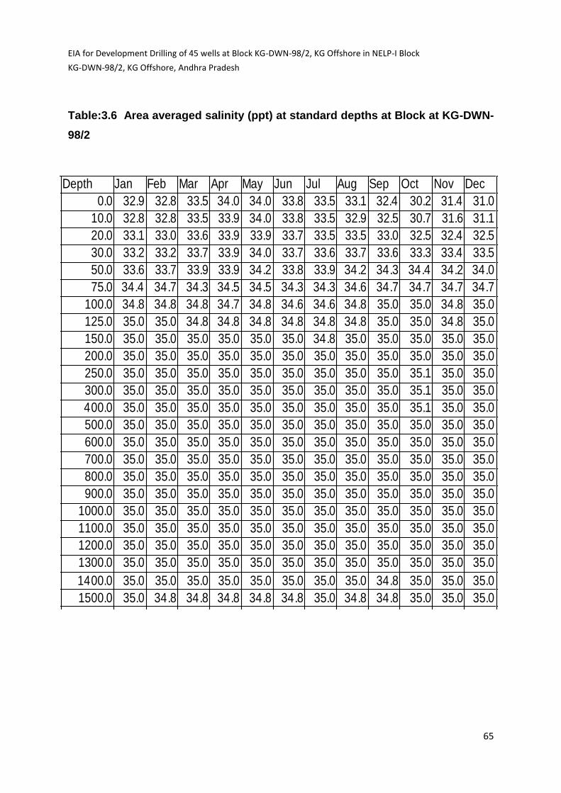
EIA for Development Drilling of 45 wells at Block KG-DWN-98/2, KG Offshore in NELP-I Block
KG-DWN-98/2, KG Offshore, Andhra Pradesh
65
Table:3.6 Area averaged salinity (ppt) at standard depths at Block at KG-DWN-
98/2
KG-0098-2-SALDepth Jan Feb Mar Apr May Jun Jul Aug Sep Oct Nov Dec
0.0 32.9 32.8 33.5 34.0 34.0 33.8 33.5 33.1 32.4 30.2 31.4 31.0
10.0 32.8 32.8 33.5 33.9 34.0 33.8 33.5 32.9 32.5 30.7 31.6 31.1
20.0 33.1 33.0 33.6 33.9 33.9 33.7 33.5 33.5 33.0 32.5 32.4 32.5
30.0 33.2 33.2 33.7 33.9 34.0 33.7 33.6 33.7 33.6 33.3 33.4 33.5
50.0 33.6 33.7 33.9 33.9 34.2 33.8 33.9 34.2 34.3 34.4 34.2 34.0
75.0 34.4 34.7 34.3 34.5 34.5 34.3 34.3 34.6 34.7 34.7 34.7 34.7
100.0 34.8 34.8 34.8 34.7 34.8 34.6 34.6 34.8 35.0 35.0 34.8 35.0
125.0 35.0 35.0 34.8 34.8 34.8 34.8 34.8 34.8 35.0 35.0 34.8 35.0
150.0 35.0 35.0 35.0 35.0 35.0 35.0 34.8 35.0 35.0 35.0 35.0 35.0
200.0 35.0 35.0 35.0 35.0 35.0 35.0 35.0 35.0 35.0 35.0 35.0 35.0
250.0 35.0 35.0 35.0 35.0 35.0 35.0 35.0 35.0 35.0 35.1 35.0 35.0
300.0 35.0 35.0 35.0 35.0 35.0 35.0 35.0 35.0 35.0 35.1 35.0 35.0
400.0 35.0 35.0 35.0 35.0 35.0 35.0 35.0 35.0 35.0 35.1 35.0 35.0
500.0 35.0 35.0 35.0 35.0 35.0 35.0 35.0 35.0 35.0 35.0 35.0 35.0
600.0 35.0 35.0 35.0 35.0 35.0 35.0 35.0 35.0 35.0 35.0 35.0 35.0
700.0 35.0 35.0 35.0 35.0 35.0 35.0 35.0 35.0 35.0 35.0 35.0 35.0
800.0 35.0 35.0 35.0 35.0 35.0 35.0 35.0 35.0 35.0 35.0 35.0 35.0
900.0 35.0 35.0 35.0 35.0 35.0 35.0 35.0 35.0 35.0 35.0 35.0 35.0
1000.0 35.0 35.0 35.0 35.0 35.0 35.0 35.0 35.0 35.0 35.0 35.0 35.0
1100.0 35.0 35.0 35.0 35.0 35.0 35.0 35.0 35.0 35.0 35.0 35.0 35.0
1200.0 35.0 35.0 35.0 35.0 35.0 35.0 35.0 35.0 35.0 35.0 35.0 35.0
1300.0 35.0 35.0 35.0 35.0 35.0 35.0 35.0 35.0 35.0 35.0 35.0 35.0
1400.0 35.0 35.0 35.0 35.0 35.0 35.0 35.0 35.0 34.8 35.0 35.0 35.0
1500.0 35.0 34.8 34.8 34.8 34.8 34.8 35.0 34.8 34.8 35.0 35.0 35.0

EIA for Development Drilling of 45 wells at Block KG-DWN-98/2, KG Offshore in NELP-I Block
KG-DWN-98/2, KG Offshore, Andhra Pradesh
66
Fig: 3.5 Surface Distribution of Salinity in the Bay of Bengal

EIA for Development Drilling of 45 wells at Block KG-DWN-98/2, KG Offshore in NELP-I Block
KG-DWN-98/2, KG Offshore, Andhra Pradesh
67
Table: 3.7 Area averaged temperature (0C) at standard depths at KG-DWN-98/2
KG-0098-2.tempr Depth Jan Feb Mar Apr May Jun Jul Aug Sep Oct Nov Dec
0.0 26.3 26.4 27.9 29.0 30.2 29.6 28.9 28.6 29.5 28.3 27.1 26.7
10.0 26.1 26.4 27.8 28.8 30.1 29.4 28.8 28.2 29.1 28.4 27.2 26.8
20.0 26.3 26.3 27.7 28.5 30.0 29.2 28.8 28.0 28.9 28.3 27.7 27.5
30.0 26.4 26.2 27.6 28.2 29.7 28.9 28.8 27.8 28.8 28.1 27.4 27.7
50.0 26.7 25.8 26.6 27.0 28.1 28.2 28.1 27.3 26.7 26.5 26.1 26.5
75.0 25.2 24.4 24.8 24.6 25.9 26.6 25.9 26.1 24.5 23.0 22.3 23.8
100.0 22.8 21.3 23.5 22.1 23.8 23.5 22.8 22.9 21.9 19.8 19.0 20.3
125.0 19.6 19.0 21.1 19.8 20.9 21.1 20.4 19.8 19.4 17.6 16.8 18.1
150.0 17.7 17.0 18.4 17.5 18.5 18.4 17.6 17.3 17.4 15.8 15.1 16.5
200.0 14.7 14.1 14.8 14.7 14.7 14.6 14.1 14.2 14.4 13.6 13.3 13.8
250.0 12.9 12.5 12.8 12.6 13.0 12.8 12.6 12.6 12.7 12.2 12.1 12.4
300.0 11.4 11.6 11.6 11.6 11.7 11.6 11.7 11.7 12.0 11.3 11.3 11.5
400.0 10.6 10.4 10.4 10.3 10.4 10.3 10.5 10.7 10.7 10.5 10.3 10.6
500.0 9.8 9.6 9.6 9.5 9.4 9.8 9.7 9.8 9.7 9.9 9.7 9.9
600.0 9.2 8.8 8.8 8.6 8.6 9.0 8.9 9.0 9.2 8.9 9.0 9.4
700.0 8.5 8.2 8.1 8.1 7.9 8.0 8.2 8.3 8.5 8.4 8.4 8.7
800.0 8.0 7.4 7.5 7.5 7.3 7.3 7.5 7.6 7.6 7.7 7.9 7.9
900.0 7.3 6.9 7.0 7.0 6.8 6.9 7.0 7.1 7.1 7.1 7.3 7.2
1000.0 6.6 6.7 6.6 6.5 6.5 6.6 6.5 6.6 6.5 6.6 6.7 6.6
1100.0 6.2 6.1 6.0 6.0 6.0 6.1 6.0 6.1 5.9 6.1 6.3 6.1
1200.0 5.5 5.6 5.6 5.3 5.3 5.4 5.4 5.6 5.5 5.7 5.8 5.7
1300.0 5.2 5.2 5.1 5.2 5.2 5.2 4.9 5.2 5.1 5.3 5.3 5.3
1400.0 4.7 4.7 4.7 4.7 4.7 4.6 4.5 4.8 4.7 4.8 4.7 4.9
1500.0 4.2 4.3 4.3 4.1 4.0 4.0 4.4 4.3 4.3 4.5 4.5 4.5

EIA for Development Drilling of 45 wells at Block KG-DWN-98/2, KG Offshore in NELP-I Block
KG-DWN-98/2, KG Offshore, Andhra Pradesh
68
Fig:3.6 Sea Surface Temperature

EIA for Development Drilling of 45 wells at Block KG-DWN-98/2, KG Offshore in NELP-I Block
KG-DWN-98/2, KG Offshore, Andhra Pradesh
69
Fig: 3.7 Sea water collections at different sampling point

EIA for Development Drilling of 45 wells at Block KG-DWN-98/2, KG Offshore in NELP-I Block
KG-DWN-98/2, KG Offshore, Andhra Pradesh
70
Table: 3.8 Water Quality Data
Method of analysis: Cd, Iron, Ni, Zn, Pb, Cr, by AAS (IS3025):
PAH by GC (APHA 6440B) COD, DO, pH Oil & Grease, Alk, Hardness by
IS3025, BOD by APHA 4500C.
Minimum Detection Limits : Iron 0.1 mg/l, Copper 0.05 mg/l, Lead 0.05 mg/l, Zinc 0.5 mg/l,
Chromium 0.05 mg/l, Aluminium 0.03 mg/l, Nickel 1.0 mg/l,
Cadmium 0.01 mg/l, Mercury 0.001 mg/l, PAH 0.1 µg/l
Sl.
No
Parameter Unit S1 S2 S3 S4 S5 S6 S7 S8 S9
1 pH mg/l 7.6 7.9 7.9 7.7 7.8 7.76 7.69 7.83 7.86
2 Salinity ppt 33.1 33.3 32.9 33.3 33.7 33.8 33.7 33.9 33.9
3 Turbidity NTU 3.1 3.0 4.0 3.6 4.0 3.5 3.2 3.1 3.4
4 DO mg/l 6.0 6.0 6.3 6.2 6.2 6.0 6.1 6.3 6.2
5 BOD mg/l 7.1 8.4 6.2 7.2 6.4 4.1 3.7 4.8 4.6
6 COD mg/l 25.5 28.0 20.5 22.5 20.2 11.9 13.2 12.5 9.9
7 PAH µg/l BDL BDL BDL BDL BDL BDL BDL BDL BDL
8 Oil content µg/l 3.9 3.2 3.3 2.9 3.6 2.6 2.9 3.0 3.1
9 Alkalinity mg/l 214 210 208 196 188 311 361 377 383
10 Total
Hardness
mg/l 6065 6800 6066 6265 6380 6316 6076 5921 5883
11 Chloride g/l 16.23 15.02 16.03 15.17 16.25 16.19 12.39 10.59 11.64
12 Fluoride mg/l 5.5 5.6 5.2 5.0 4.8 2.31 2.74 2.68 2.38
13 Cadmium mg/l BDL BDL BDL BDL BDL BDL BDL BDL BDL
14 Iron mg/l 1.62 1.4 1.62 1.58 1.3 0.23 0.25 0.19 0.22
15 Nickel mg/l BDL BDL BDL BDL BDL BDL BDL BDL BDL
16 Zinc mg/l 0.74 0.72 0.75 0.67 0.62 0.71 0.68 0.73 0.72
17 Lead mg/l BDL BDL BDL BDL BDL BDL BDL BDL BDL
18 Chromium mg/l BDL BDL BDL BDL BDL BDL BDL BDL BDL

EIA for Development Drilling of 45 wells at Block KG-DWN-98/2, KG Offshore in NELP-I Block
KG-DWN-98/2, KG Offshore, Andhra Pradesh
71
Under the influence of the buffering action of CO32-/HCO3
2-/CO2 system, the pH of
oxygenated seawater at the surface is fairly constant and varies in a narrow range.
The variation in the pH value near the study area is 7.6-7.9.
It is observed that the Dissolved Oxygen (DO) content shows high seasonal
variation. Lowest oxygen concentrations are observed in winter while higher oxygen
levels in the monsoon season. The intensity of the incident solar radiation is very
high in the pre monsoon, which causes maximum primary production to occur a few
metres below the sea surface thus, a DO maximum occasionally occurs in this layer.
The DO concentrations in the surface mixed layer in the Bay of Bengal are generally
uniform and close to the saturation value. Lowest oxygen concentrations are
observed in winter due to enhanced surface productivity in winter, the large amounts
of organic matter should be oxidized in intermediate layers, thus leading to oxygen-
deficient conditions. Surface DO concentrations could be considerably lower than the
saturation value in some areas and during the periods of upwelling when DO
deficient sub-surface water reaches the surface.
It is evident that the average DO is 6.1 mg/l in the studied are of this block and is
generally close to saturation indicating prevailing good oxidising conditions. The
observed DO values in KG-DWN-98/2 block are in the range of 6.0 mg/l to 6.3 mg.
Heavy metals namely mercury, chromium, lead, cadmium, aluminium, copper and
chromium were below the detectable range in all the sampling locations. The
concentration of iron was detectable in all the sampling locations, which was in the
range of 0.13 to 1.62 mg/L.
The concentrations of dissolved and dispersed Petroleum hydrocarbons (PHC) in
the study area are low and uniformly distributed. The observed values of Petroleum
hydrocarbons at different sampling locations in this block are in the range of 2.6 to
3.9 μg/L.
The literature data obtained from the published paper PHC varies in range of 1.6 to
14.8 μg/ l (Source: Sharma , V.V (1996) Petroleum hydrocarbons and trace metals in
Viskhapatnam harbor and Kakinada bay , eastcoast of India , Indian Journal of
Marine Species, Vol.-25, pp-, 148-150. )

EIA for Development Drilling of 45 wells at Block KG-DWN-98/2, KG Offshore in NELP-I Block
KG-DWN-98/2, KG Offshore, Andhra Pradesh
72
In common with land plants, marine phytoplankton requires certain trace elements
for their healthy growth. The most important of these are nitrogen and phosphorus,
which may be taken-up by them from the water to such an extent that their further
growth is inhibited. The average concentrations of dissolved phosphorus and
nitrogen compounds vary considerably in the study area and their variation in
concentration is presented below in Table: 3.9
Table: 3.9 Average concentrations of dissolved phosphorus and nitrogen compounds
Source: * TripathyS.C. et al., 2001, Water quality assessment of Gautami Godavari
mangrove estuarine ecosystem of Andhra Pradesh, India. # Raman A.V. et al, 2005,
Macrobenthof of Kakinada Bay in the Godavari Delta, East Coast of India: comparing
decadal changes, Estuaraine Coastal and Shelf Science, Vol. 62, page 609 – 620
The average concentration of PO43--P and NO3
--N in the northern part of this block
was observed between 2.34 – 2.98 µmol/l and 9.96-12.02 µmol/l respectively. The
levels of NO2-N and NH4+N are low as expected for oxic coastal waters. The average
N: P ratio in the upper 100 m of the Bay of Bengal has been reported to be also low
and has been attributed to the reduction of NO3--N as a result of de-nitrification
associated with the advective transport of P from deeper layers.
3.5 Biological Environment
The occurrence of marine species - both flora and fauna has largely been controlled
by the physico-chemical properties of sea water. Water discharges from the
surrounding river catchments carry huge influx of sediments full of nutrients to the
Parameter 2001 *
2005 #
S1 S2 S3 S4 S5 S6 S7 S8 S9
PO4-3
(µmol/l)
1.76-
4.53
0.92-
6.9
2.98 2.85 2.78 2.59 2.62 2.64 2.29 2.46 2.34
NO3- -
(µmol/l)
7.4-
16.2
13.9-
21.4
12.02 11.39 11.52 11.65 10.36 10.78 10.01 9.92 9.86
NO2- -
(µmol/l)
0.98-
1.72
0.50-
2.24
1.42 1.02 1.62 1.69 0.85 0.82 1.02 0.94 0.92
NH4+
(µmol/l)
0.79-
14.2
0.33-
2.25
2.51 1.55 2.01 1.96 0.76 0.68 0.94 0.60 0.58
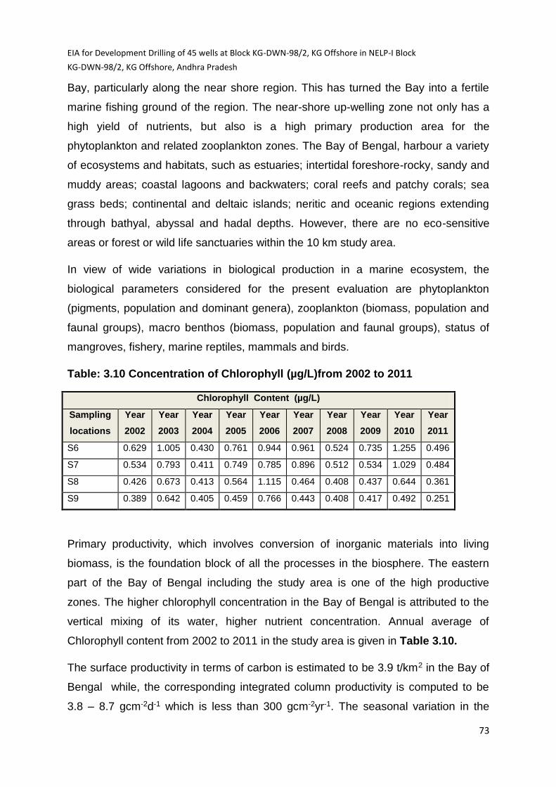
EIA for Development Drilling of 45 wells at Block KG-DWN-98/2, KG Offshore in NELP-I Block
KG-DWN-98/2, KG Offshore, Andhra Pradesh
73
Bay, particularly along the near shore region. This has turned the Bay into a fertile
marine fishing ground of the region. The near-shore up-welling zone not only has a
high yield of nutrients, but also is a high primary production area for the
phytoplankton and related zooplankton zones. The Bay of Bengal, harbour a variety
of ecosystems and habitats, such as estuaries; intertidal foreshore-rocky, sandy and
muddy areas; coastal lagoons and backwaters; coral reefs and patchy corals; sea
grass beds; continental and deltaic islands; neritic and oceanic regions extending
through bathyal, abyssal and hadal depths. However, there are no eco-sensitive
areas or forest or wild life sanctuaries within the 10 km study area.
In view of wide variations in biological production in a marine ecosystem, the
biological parameters considered for the present evaluation are phytoplankton
(pigments, population and dominant genera), zooplankton (biomass, population and
faunal groups), macro benthos (biomass, population and faunal groups), status of
mangroves, fishery, marine reptiles, mammals and birds.
Table: 3.10 Concentration of Chlorophyll (µg/L)from 2002 to 2011
Chlorophyll Content (µg/L)
Sampling
locations
Year
2002
Year
2003
Year
2004
Year
2005
Year
2006
Year
2007
Year
2008
Year
2009
Year
2010
Year
2011
S6 0.629 1.005 0.430 0.761 0.944 0.961 0.524 0.735 1.255 0.496
S7 0.534 0.793 0.411 0.749 0.785 0.896 0.512 0.534 1.029 0.484
S8 0.426 0.673 0.413 0.564 1.115 0.464 0.408 0.437 0.644 0.361
S9 0.389 0.642 0.405 0.459 0.766 0.443 0.408 0.417 0.492 0.251
Primary productivity, which involves conversion of inorganic materials into living
biomass, is the foundation block of all the processes in the biosphere. The eastern
part of the Bay of Bengal including the study area is one of the high productive
zones. The higher chlorophyll concentration in the Bay of Bengal is attributed to the
vertical mixing of its water, higher nutrient concentration. Annual average of
Chlorophyll content from 2002 to 2011 in the study area is given in Table 3.10.
The surface productivity in terms of carbon is estimated to be 3.9 t/km2 in the Bay of
Bengal while, the corresponding integrated column productivity is computed to be
3.8 – 8.7 gcm-2d-1 which is less than 300 gcm-2yr-1. The seasonal variation in the
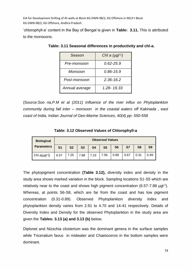
EIA for Development Drilling of 45 wells at Block KG-DWN-98/2, KG Offshore in NELP-I Block
KG-DWN-98/2, KG Offshore, Andhra Pradesh
74
‘chlorophyll-a’ content in the Bay of Bengal is given in Table: 3.11. This is attributed
to the monsoons.
Table: 3.11 Seasonal differences in productivity and chl-a.
Season Chl a (µgl-1)
Pre-monsoon 0.62-25.9
Monsoon 0.86-15.9
Post-monsoon 2.36-16.2
Annual average 1.28- 19.33
(Source:Soo ria,P.M et al (2011) Influence of the river influx on Phytoplankton
community during fall inter – monsoon in the coastal waters off Kakinada , east
coast of India, Indian Journal of Geo-Marine Sciences, 40(4) pp- 550-558
Table: 3.12 Observed Values of Chlorophyll-a
Biological
Parameters
Observed Values
S1 S2 S3 S4 S5 S6 S7 S8 S9
Chl a(µgl-1) 6.57 7.25 7.88 7.23 7.56 0.89 0.67 0.31 0.49
The phytopigment concentration (Table 3.12), diversity index and density in the
study area shows marked variation in the block. Sampling locations S1-S5 which are
relatively near to the coast and shows high pigment concentration (6.57-7.88 µgl-1).
Whereas, at points S6-S8, which are far from the coast and has low pigment
concentration (0.31-0.89). Observed Phytoplankton diversity index and
phytoplankton density varies from 2.91 to 4.70 and 14-41 respectively. Details of
Diversity Index and Density for the observed Phytoplankton in the study area are
given the Tables: 3.13 (a) and 3.13 (b) below.
Diplonet and Nizschia closterium was the dominant genera in the surface samples
while Triceratium favus in midwater and Chaetoceros in the bottom samples were
dominant.

EIA for Development Drilling of 45 wells at Block KG-DWN-98/2, KG Offshore in NELP-I Block KG-DWN-98/2, KG
Offshore, Andhra Pradesh
62
Table: 3.13 (a) Observed values of Phyto-planktons in S1-S5.
S. No.
Name of Phyto-plankton
S1
S2
S3
S4
S5
Diversity Index Density
(Individual/Litre)
S1 S2 S3 S4 S5
S1
S2
S3
S4
S5
1 Rhodophyta y y y Y y
4.
6
4.
55
4.
30
2.
91
4.
7
1
6
1
4
1
7
2
3
1
8
2 Phaeophyta y y y Y y
3 Achnanthes
stromii
x y y y x
4 Aulacodiscus
orbiculatus
x y x y x
5 Ceratium belone x x x y x
6 Coscinodiscus
lineatus
x y y x x
7 Nitzschia
forcipata
x y x y x
8 Triceratium
favus
y y y y y
9 Diplonets sp. y y y y y
1
0
Amphidinium
curcubita
y y y y y
1
1
Ornithocercus
heteroporus
y y y x y
1
2
Lyngpyamajuscu
la
x y x y x
1
3
Oscillatoria
acutillsima
x x x y x
1
4
Cyclotella striata y y y y y
1
5
Amphidium
klabsie
x y y y y
1
6
Bacillariaparatox
a
x y x y x
1
7
Gymnodinium
falcatum
y y x y x
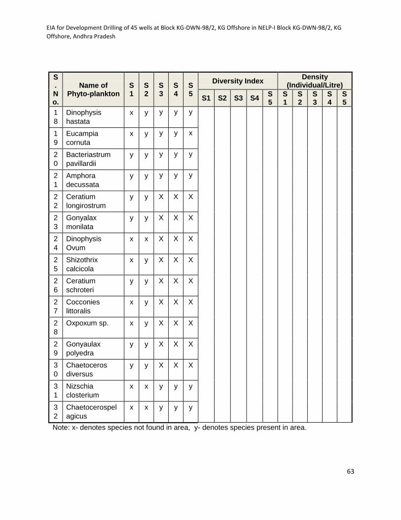
EIA for Development Drilling of 45 wells at Block KG-DWN-98/2, KG Offshore in NELP-I Block KG-DWN-98/2, KG
Offshore, Andhra Pradesh
63
S. No.
Name of Phyto-plankton
S1
S2
S3
S4
S5
Diversity Index Density
(Individual/Litre)
S1 S2 S3 S4 S5
S1
S2
S3
S4
S5
1
8
Dinophysis
hastata
x y y y y
1
9
Eucampia
cornuta
x y y y x
2
0
Bacteriastrum
pavillardii
y y y y y
2
1
Amphora
decussata
y y y y y
2
2
Ceratium
longirostrum
y y X X X
2
3
Gonyalax
monilata
y y X X X
2
4
Dinophysis
Ovum
x x X X X
2
5
Shizothrix
calcicola
x y X X X
2
6
Ceratium
schroteri
y y X X X
2
7
Cocconies
littoralis
x y X X X
2
8
Oxpoxum sp. x y X X X
2
9
Gonyaulax
polyedra
y y X X X
3
0
Chaetoceros
diversus
y y X X X
3
1
Nizschia
closterium
x x y y y
3
2
Chaetocerospel
agicus
x x y y y
Note: x- denotes species not found in area, y- denotes species present in area.

EIA for Development Drilling of 45 wells at Block KG-DWN-98/2, KG Offshore in NELP-I Block KG-DWN-98/2, KG
Offshore, Andhra Pradesh
64
Table: 3.13 (b) Observed values of Phyto-planktons in S6-S9.
S
No.
Name of the
phytoplankton
S
6
S
7
S
8
S
9
Diversity index Density (No. of
individuals/Litre)
S6 S7 S8 S9 S6 S7 S8 S9
Spermatophyta
3.
1
4.
2
4.
7
3.
5
19
26
41
23
1 Azolla Sp. X X X x
2 Spirodela Sp. Y y y x
3 Wolffia Sp. y X x Y
Chlorophyta
1 Westella x X x y
2 Selenastrum x X x X
3 Zygnema Sp. x X x X
4 Chlorella Sp. X X x X
5 Clostrium Sp x X x X
6 Mougeotia Sp X X x X
7 Oocystis Sp. X X x X
8 Sitchococcos
Sp.
X X x Y
9 Tetrastrum
Sp.
X X x Y
10 Crucigenia
Sp.
X X x Y
11 Pithopora Sp. x X x y
12 Chalamydomo
nas Sp
x y Y X
13 Pediastrum
Sp.
x y Y X
14 Volvox Sp. x y X X
15 Zygnema Sp. y y X X
16 Ulothrix Sp. x y Y X
17 Dictyosphaeri
um Sp
x X Y X
18 Schizomeris
Sp.
x X X X

EIA for Development Drilling of 45 wells at Block KG-DWN-98/2, KG Offshore in NELP-I Block KG-DWN-98/2, KG
Offshore, Andhra Pradesh
65
S
No.
Name of the
phytoplankton
S
6
S
7
S
8
S
9
Diversity index Density (No. of
individuals/Litre)
S6 S7 S8 S9 S6 S7 S8 S9
19 Euastrum Sp. y X X X
20 Actinastrum
Sp.
y X X X
21 Nitella Sp. x X Y X
Cyanophyta
1 Gloetrichia
Sp.
x Y X X
2 Phormidium
Sp.
y X Y Y
3 Lingbya Sp. y X Y Y
4 Oscillatoria
Sp.
y Y Y Y
5 Fragelira Sp. x X X X
6 Althrospira
Sp.
x X Y X
7 Cylindrosperm
um Sp
y X X Y
8 Anabena Sp. x Y X X
9 Anacystis Sp. x Y X x
Diatoms
(Bacillareophyceae)
1 Tabellaria Sp. y Y Y Y
2 Synedra Sp. y y Y Y
Chrysophyta
1 Cocconeis Sp. y y Y Y
2 Achnanthes
Sp.
y y Y Y
3 Cyclotella Sp. y y Y Y
4 Rhizosolenia
Sp
y y Y Y
Xanthothytea
1 Botryococcus y y Y Y

EIA for Development Drilling of 45 wells at Block KG-DWN-98/2, KG Offshore in NELP-I Block KG-DWN-98/2, KG
Offshore, Andhra Pradesh
66
S
No.
Name of the
phytoplankton
S
6
S
7
S
8
S
9
Diversity index Density (No. of
individuals/Litre)
S6 S7 S8 S9 S6 S7 S8 S9
Sp.
Rhobophyta
1 Gracilaria Sp. y x X x
2 Champia Sp. y x X x
Note: x- denotes species not found in area, y- denotes species present in area.
Zooplankton
The secondary production has been estimated to be 18.5 mgC/m2/d for the Bay
of Bengal, with the corresponding annual production rate of 6.0 x 10⁶ t C/y. The
observed zooplankton Diversity Index in the studied area varies from 1.74 to 3.46
whereas; the density varies from 9 to 28 individuals/litre. Details of Diversity
Index and Density for the observed zooplankton in the study area are given the
details given in Table 3.14 (a) and (b).
Table: 3.14 (a) Observed values of Zooplankton in S1-S5.
S.
No
.
Name of
Zoo-
Planktons
S
1
S
2
S
3
S
4
S
5
Diversity Index Density
(Individual/Litre)
S1 S2 S3 S4 S5 S
1
S
2
S
3
S
4
S
5
1 Foraminifera x x x x x
2.6
3
1.9
4
3.4
6
1.9
4
1.9
6
9
1
3
1
6
1
1
1
5
2 Decapoda y y y y y
3 Ciliata y y y y y
4 Hydrozoa y y y y y
5 Rotifera y y y y y
(i)
Brachionus
sp.
y y y y y
(ii)Ashplanc
he brighwelli
x x y y y
(iii) Stentor
sp.
x x y x y
6 Chaetognat x x y y y
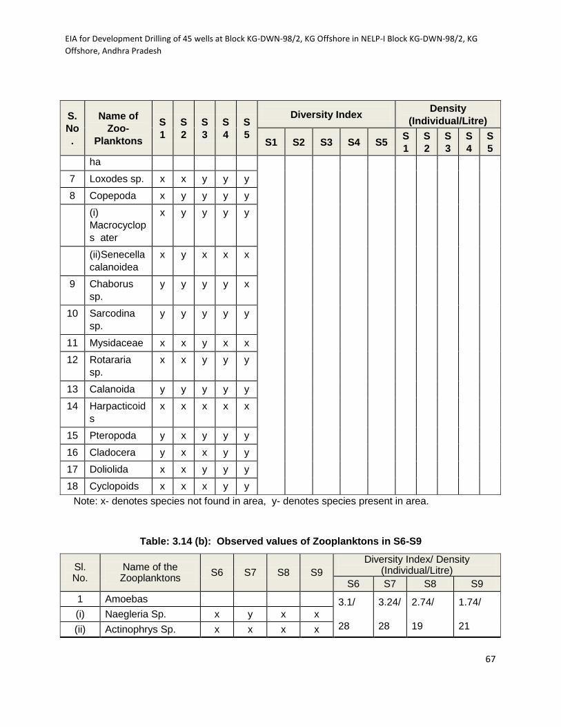
EIA for Development Drilling of 45 wells at Block KG-DWN-98/2, KG Offshore in NELP-I Block KG-DWN-98/2, KG
Offshore, Andhra Pradesh
67
S.
No
.
Name of
Zoo-
Planktons
S
1
S
2
S
3
S
4
S
5
Diversity Index Density
(Individual/Litre)
S1 S2 S3 S4 S5 S
1
S
2
S
3
S
4
S
5
ha
7 Loxodes sp. x x y y y
8 Copepoda x y y y y
(i)
Macrocyclop
s ater
x y y y y
(ii)Senecella
calanoidea
x y x x x
9 Chaborus
sp.
y y y y x
10 Sarcodina
sp.
y y y y y
11 Mysidaceae x x y x x
12 Rotararia
sp.
x x y y y
13 Calanoida y y y y y
14 Harpacticoid
s
x x x x x
15 Pteropoda y x y y y
16 Cladocera y x x y y
17 Doliolida x x y y y
18 Cyclopoids x x x y y
Note: x- denotes species not found in area, y- denotes species present in area.
Table: 3.14 (b): Observed values of Zooplanktons in S6-S9
Sl. No.
Name of the Zooplanktons
S6 S7 S8 S9
Diversity Index/ Density (Individual/Litre)
S6 S7 S8 S9
1 Amoebas 3.1/
28
3.24/
28
2.74/
19
1.74/
21
(i) Naegleria Sp. x y x x
(ii) Actinophrys Sp. x x x x

EIA for Development Drilling of 45 wells at Block KG-DWN-98/2, KG Offshore in NELP-I Block KG-DWN-98/2, KG
Offshore, Andhra Pradesh
68
Sl. No.
Name of the Zooplanktons
S6 S7 S8 S9
Diversity Index/ Density (Individual/Litre)
S6 S7 S8 S9
(iii) Acanthamoeba Sp. x x x y
2 Coelenterates
(i) Hydra Sp. y y x x
(ii) Anthopleura Sp. y y x x
(iii) Obelia Sp. x x y x
3 Rotifers
(i) Philodina Sp. y y y x
(ii) Euchlanis Sp. y y y y
(iii) Proales Sp. y y x x
(iv) Flagellates Sp. y y x x
(a) Ceratium y y x x
(b) Peridinium y y x x
(v) Filinia Sp. x x x x
(vi) Keratella Sp. x x x x
(vii) Epiphanas x x x y
(viii) Monostyla x x y y
(ix) Kellicottia Sp. x x y x
(x) Brachionus Sp. x x x x
4 Cladocera
(i) Daphnia Sp. x y x y
(ii) Alona y x x x
5 Ostracoda
(i) Ostracod Sp. y y y x
6 Mysidacea
(i) Holmesimysia Sp. y y x y
7 Cirripedia
(i) Balanus Sp. y y x y
8 Flagellaes
(i) Haematococcus Sp. x x x x
(ii) Chromulina Sp. x x x x
(iii) Ochromonas Sp. x x x x
(iv) Astasia Sp. x x x x
(v) Lobomonas Sp. x x x x

EIA for Development Drilling of 45 wells at Block KG-DWN-98/2, KG Offshore in NELP-I Block KG-DWN-98/2, KG
Offshore, Andhra Pradesh
69
Sl. No.
Name of the Zooplanktons
S6 S7 S8 S9
Diversity Index/ Density (Individual/Litre)
S6 S7 S8 S9
(vi) Petromonas Sp. x x x x
(vii) Non Pigmented Sp. x x x x
(a) Dinomonas Sp. x x x x
9 Leptostraca
(i) Epinebalia Sp. x x x y
10 Cumacea
(i) Oxyurostylis Sp. x x x y
11 Ciliates
(i) Lionotus Sp. x x y y
(ii) Pleuronenema Sp. x x y y
(iii) Colpoda Sp. x x x y
(iv) Aspidisca Sp. x x x y
12 Cladophora x x y x
13 Copepoda
(i) Diaptomus x x y x
14 Crustacea
(i) Daphnia Sp. x x y x
(ii) Cyclops Sp. x x y x
Note: x -denote species not found in area and y- denote species present in area
Benthos
Benthos, the seafloor biota, contributes substantially to the secondary production
as also to the potential and sustainability of demersal or near bottom living
fishable resources. The sub-tidal benthic standing stock in terms of diversity
index and density varied from 1.28 to 1.42 and 12 to 14 individual /litre
respectively, given in Table 3.15 along with the identify benthos in the study area.
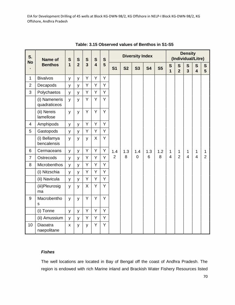
EIA for Development Drilling of 45 wells at Block KG-DWN-98/2, KG Offshore in NELP-I Block KG-DWN-98/2, KG
Offshore, Andhra Pradesh
70
Table: 3.15 Observed values of Benthos in S1-S5
S.
No
.
Name of
Benthos
S
1
S
2
S
3
S
4
S
5
Diversity Index Density
(Individual/Litre)
S1 S2 S3 S4 S5 S
1
S
2
S
3
S
4
S
5
1 Bivalvos y y Y Y Y
1.4
2
1.3
8
1.4
0
1.3
6
1.2
8
1
4
1
2
1
4
1
4
1
2
2 Decapods y y Y Y Y
3 Polychaetos y y Y Y Y
(i) Nameneris
quadraticeos
y y Y Y Y
(ii) Nereis
lamellose
y y Y Y Y
4 Amphipods y y Y Y Y
5 Gastopods y y Y Y Y
(i) Bellamya
bencalensis
y y y X Y
6 Cermaceans y y Y Y Y
7 Ostrecods y y Y Y Y
8 Microbenthos y y Y Y Y
(i) Nitzschia y y Y Y Y
(ii) Navicula y y Y Y Y
(iii)Pleurosig
ma
y y X Y Y
9 Macrobentho
s
y y Y Y Y
(i) Tonne y y Y Y Y
(ii) Amussium y y Y Y Y
10 Diaoatra
naepolitane
x y y Y Y
Fishes
The well locations are located in Bay of Bengal off the coast of Andhra Pradesh. The
region is endowed with rich Marine inland and Brackish Water Fishery Resources listed
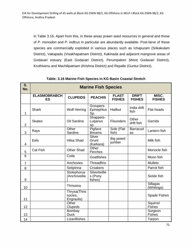
EIA for Development Drilling of 45 wells at Block KG-DWN-98/2, KG Offshore in NELP-I Block KG-DWN-98/2, KG
Offshore, Andhra Pradesh
71
in Table 3.16. Apart from this, in these areas prawn seed resources in general and those
of P. monodon and P. indlcus in particular are abundantly available. Post-larve of these
species are commercially exploited in various places such as Ichapuram (Srikakulam
District), Vakapadu (Visakhapatnam District), Kakinada and adjacent mangrove areas of
Godavari estuary (East Godavari District), Perumpalom (West Godavari District),
Kruthivenu and Machilipatnam (Krishna District) and Repalle (Guntur District).
Table: 3.16 Marine Fish Species in KG Basin Coastal Stretch
S. No.
Marine Fish Species
ELASMOBRABCH
ES CLUPEIDS PEACHIS
FLAST FISHES
DRIFT FISHES
MISC. FISHES
1 Shark Wolf Herring
Groupers-Epinephlus Sp.
Halibut India drift fish
Flat heads
2 Skates Oil Sardine
Shappets-Lutjanus sp.
Flounders Other drift fish
Gerrids
3 Rays
Other Sardine
Pigface Breams
Sole (Flat fish)
Barracudas
Lantern fish
4 Eels Hilsa Shad
Silver Grunt (Karkara)
Big jawed jumber
Milk fish
5 Cat Fish Other Shad
Other Perches
Monocle fish
6 Coila Goatfishes Moon fish
7 Anchovies Threadfins Mullets
8 Setipinna Croakers Parrot fish
9
Stolephorus (Anchoveilla)
Silverbellies (Pony fishes)
Sickle fish
10 Thrissina
Sillagas (Whitings)
11
Thrysa(Thrissocies, Engraulis)
Spade Fishes
12
Other Clupeds
Squirrel Fishes
13
Bombay Duck
Surgeon Fishes
14 Lizardfishes Tarpon
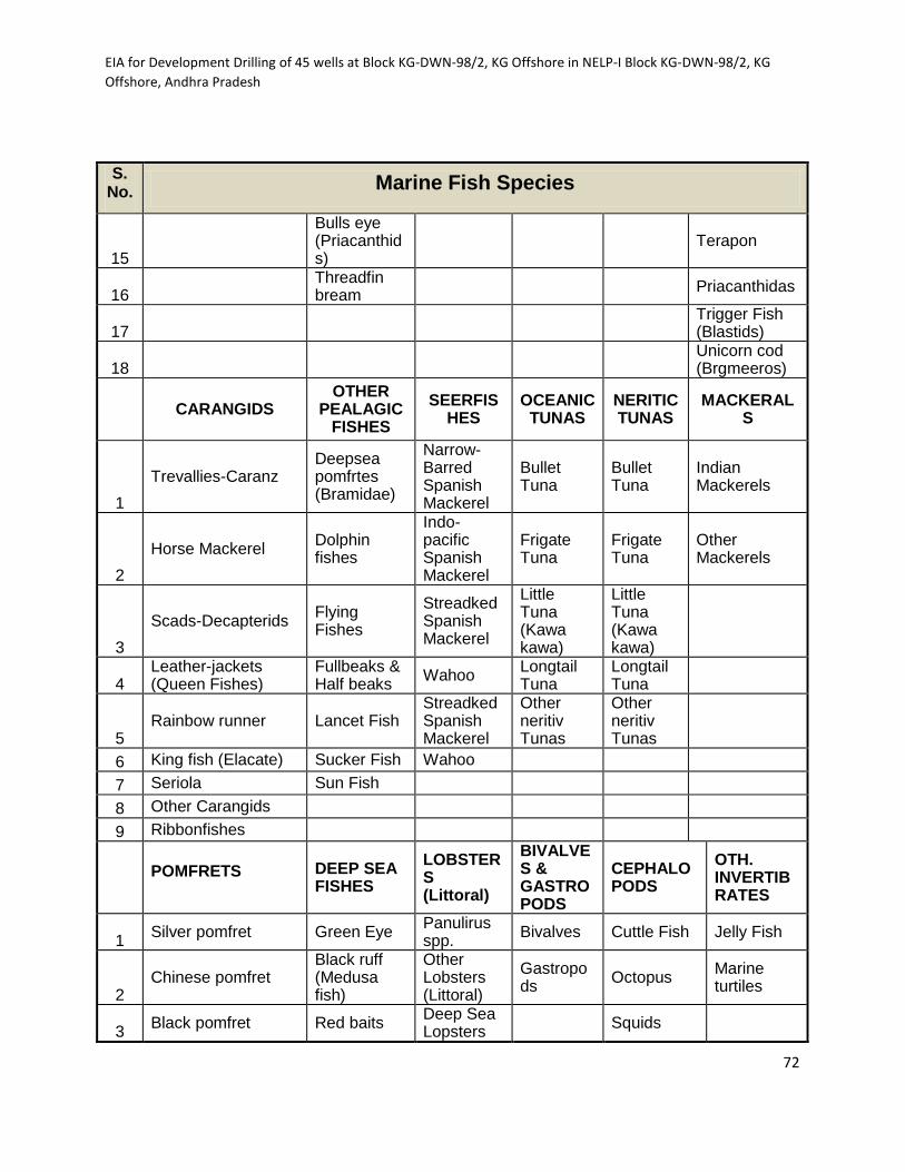
EIA for Development Drilling of 45 wells at Block KG-DWN-98/2, KG Offshore in NELP-I Block KG-DWN-98/2, KG
Offshore, Andhra Pradesh
72
S. No.
Marine Fish Species
15
Bulls eye (Priacanthids)
Terapon
16
Threadfin bream
Priacanthidas
17
Trigger Fish (Blastids)
18
Unicorn cod (Brgmeeros)
CARANGIDS OTHER
PEALAGIC FISHES
SEERFISHES
OCEANIC TUNAS
NERITIC TUNAS
MACKERALS
1
Trevallies-Caranz Deepsea pomfrtes (Bramidae)
Narrow-Barred Spanish Mackerel
Bullet Tuna
Bullet Tuna
Indian Mackerels
2
Horse Mackerel Dolphin fishes
Indo-pacific Spanish Mackerel
Frigate Tuna
Frigate Tuna
Other Mackerels
3
Scads-Decapterids Flying Fishes
Streadked Spanish Mackerel
Little Tuna (Kawa kawa)
Little Tuna (Kawa kawa)
4 Leather-jackets (Queen Fishes)
Fullbeaks & Half beaks
Wahoo Longtail Tuna
Longtail Tuna
5 Rainbow runner Lancet Fish
Streadked Spanish Mackerel
Other neritiv Tunas
Other neritiv Tunas
6 King fish (Elacate) Sucker Fish Wahoo
7 Seriola Sun Fish
8 Other Carangids
9 Ribbonfishes
POMFRETS DEEP SEA FISHES
LOBSTERS (Littoral)
BIVALVES & GASTROPODS
CEPHALOPODS
OTH. INVERTIBRATES
1 Silver pomfret Green Eye
Panulirus spp.
Bivalves Cuttle Fish Jelly Fish
2 Chinese pomfret
Black ruff (Medusa fish)
Other Lobsters (Littoral)
Gastropods
Octopus Marine turtiles
3 Black pomfret Red baits
Deep Sea Lopsters
Squids
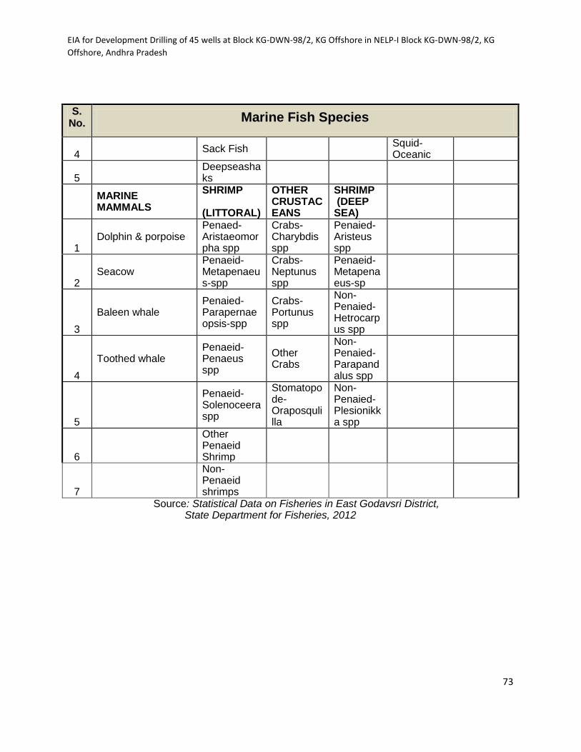
EIA for Development Drilling of 45 wells at Block KG-DWN-98/2, KG Offshore in NELP-I Block KG-DWN-98/2, KG
Offshore, Andhra Pradesh
73
S. No.
Marine Fish Species
4 Sack Fish
Squid-Oceanic
5
Deepseashaks
MARINE MAMMALS
SHRIMP (LITTORAL)
OTHER CRUSTACEANS
SHRIMP (DEEP SEA)
1 Dolphin & porpoise
Penaed-Aristaeomorpha spp
Crabs-Charybdis spp
Penaied-Aristeus spp
2 Seacow
Penaeid-Metapenaeus-spp
Crabs-Neptunus spp
Penaeid-Metapenaeus-sp
3
Baleen whale Penaied-Parapernaeopsis-spp
Crabs-Portunus spp
Non-Penaied-Hetrocarpus spp
4
Toothed whale Penaeid-Penaeus spp
Other Crabs
Non-Penaied-Parapandalus spp
5
Penaeid-Solenoceera spp
Stomatopode-Oraposqulilla
Non-Penaied-Plesionikka spp
6
Other Penaeid Shrimp
7
Non-Penaeid shrimps
Source: Statistical Data on Fisheries in East Godavsri District, State Department for Fisheries, 2012

EIA for Development Drilling of 45 wells at Block KG-DWN-98/2, KG Offshore in NELP-I Block KG-DWN-98/2, KG
Offshore, Andhra Pradesh
74
CHAPTER-4
Identification, Prediction and Evaluation of Impacts
4.1 Identification and Assessment of Impact
This section presents the likely impacts identified and recommends mitigation measures based
on the proposed project activities and the baseline information provided in Chapter-3, the
activities have potential to impact on the following environmental resources:
Table: 4.1 Identification of Potential Impacts: Activities –Impacts/Risks Interaction
Environmental Sensitivities
Physical Biological Socio-
economic
Impacts/ Risks
Activities
Air
Qu
ality
No
ise
Wa
ter
Qu
ality
Se
dim
en
t Q
uality
Aq
ua
tic
Flo
ra
Aq
ua
tic
Fa
un
a
Lo
cal fi
sh
po
pu
lati
on
Oc
cu
pati
on
al
Ex
po
su
re &
Ge
nera
l S
afe
ty
Ec
on
om
y
Positioning and deployment of
rig
Power generation at site
Drilling Operation
Well completion
Water requirement and
wastewater discharges

EIA for Development Drilling of 45 wells at Block KG-DWN-98/2, KG Offshore in NELP-I Block KG-DWN-98/2, KG
Offshore, Andhra Pradesh
75
Environmental Sensitivities
Physical Biological Socio-
economic
Impacts/ Risks
Activities
Air
Qu
ality
No
ise
Wa
ter
Qu
ality
Se
dim
en
t Q
uality
Aq
ua
tic
Flo
ra
Aq
ua
tic
Fa
un
a
Lo
cal fi
sh
po
pu
lati
on
Oc
cu
pati
on
al
Ex
po
su
re &
Ge
nera
l S
afe
ty
Ec
on
om
y
Solid Waste generation
Fuel storage and handling
Transport of personnel and
materials
Note: denotes likely impact, denotes positive impact
Based upon the above interaction matrices following potential impacts have been identified:
A. Physical
Air Quality
Noise
Water Quality
Sediment Quality
B. Biological
Aquatic flora and fauna
Local fish population
C. Socio-economic
Occupational Exposure & General Safety

EIA for Development Drilling of 45 wells at Block KG-DWN-98/2, KG Offshore in NELP-I Block KG-DWN-98/2, KG
Offshore, Andhra Pradesh
76
Economy
Drilling and other associated activities would incorporate measures for minimising adverse
environmental impacts. These impacts have been discussed in details in the following sections.
4.2 Impact Prediction
4.2.1 Impact on air environment
There are a number of sources of emissions in the offshore development drilling drilling which
include
Emissions from MODU and support vessels
Emissions from DG sets
Helicopter emissions
Fugitive emissions from diesel storage tanks
The expected pollutants raise from these sources are carbon di-oxide (CO2), oxides of nitrogen
(NOX), Sulphur dioxide (SO2), Carbon Monoxide (CO), Hydrocarbons (HCs), PM10 and PM 2.5.
Drilling consumes a considerable amount of electric power and the MODU is equipped with a
power generating capacity of 1430 kVA of each from 4 nos. of DG sets. Anticipated levels of
emissions of these gases are low. The dispersive wind conditions in the area and low emissions
levels expected suggest negligible impacts. Impacts due to CO, HC and SO2 levels at offshore
are not envisaged, considering the height of release (about 30 m above sea surface including
the height of stack of DG set i.e. 5-6 m), wind directions both in North and North East (NNE),
and wind speeds varying from 2-6 m/s, the maximum concentration of NOx at sea surface will
be around 4-5 µg/m3 at a distance of about 1 km in downwind direction. However, the offshore
drilling activity is temporary and limited to 45-90 days (under normal condition), and with a high
wind speed in the open sea area shall lead to greater dilution of pollutants, which shall increase
with increasing distance from the source. Moreover, absence of sensitive receptors shall render
the impacts due to air emission as negligible. Air emissions may result from gas flaring activities
during the well testing only (one or two days). Once the wells are completed sub-sea for
production, no well intervention is envisaged in normal operations. Only life of field services and

EIA for Development Drilling of 45 wells at Block KG-DWN-98/2, KG Offshore in NELP-I Block KG-DWN-98/2, KG
Offshore, Andhra Pradesh
77
certain mandatory sub-sea activities are envisaged, which are of short duration in nature. Hence,
no major environmental impacts are envisaged.
Table: 4.2 Emission Characteristics –Model inputs
Sl.No. Particulars DG set (4X 1430 kVA)
1. No.of engines and stacks 4
2. Height above sea level 30 m
3. Diameter 0.5
4. Gas temperature (oC) 300
5. Gas velocity (m/s) 15
6 Emission rate (g/s)
Sulphur dioxide Oxides of Nitrogen
0.0026
0.44
4.2.2 Impact on Noise Quality
High noises are likely to be generated due to DG sets, mud pumps, rig machinery and
compressors and equipment machinery on supply vessels and Helicopter during landing and
take-off. The noise levels generated from various sources during offshore exploratory drilling
operations is as follows:
Helicopter 103 to 105 dB(A)
Diesel Generators 100 to 105 dB(A)
Mud pumps 90 to 100 dB(A)
Miscellaneous 80-85 dB(A)
Rig floor 65-73 dB(A)
Accommodation 50-60 dB(A)
EIA for Development Drilling of 45 wells at Block KG-DWN-98/2, KG Offshore in NELP-I Block KG-DWN-98/2, KG
Offshore, Andhra Pradesh
78
However, these impacts shall not cause any physical damage to the marine organisms as the
propagation of sound through water is generally affected by spreading (distance) losses and
attenuation (absorption) losses with sound energy decreasing with increasing distance from the
source. Also, available information on marine fish and other marine mammals indicate that they
are unlikely to intentionally approach operations producing continuous and semi-continuous
noise and thus likely to be avoided by them (Nedwell et al., 2004 and Thomsen et al., 2006).
Therefore, the impacts on the marine fauna due to noise generation during the project activities
have been envisaged to be minimal. The effect of high noise on the people working on the rig
will be reduced by using PPE.
4.2.3 Impact on Water Quality
Number of activities related to various phases of the proposed drilling activity has the potential
to impact marine water quality and consequently marine ecology adjacent to the drilling
locations. Some near shore activities like handling of chemicals and oil may also impact marine
environment. Some of the activities which cause potential impacts to marine environment are:
The base line water quality parameters observed in the sampling areas shown in Table: 3.8 are
well below the minimum prescribed limits. The average D.O is 6.1 mg/l is close to saturation
levels and the heavy metals (Hg, Cr, Pb, Cd, Al, Cu) were below detectable limits. The
concentration of iron was in the range of 0.13 to 1.62 mg/l. Oil content in the range of 2.6 to 3.9
µg/L. As it is confirmed by ICMAM (Integrated Coastal and Marine Area Management) that the
quality of the sea water samples collected from the coast from various distances and locations
were found unpolluted and water beyond 2 km is clean in the east coast Bay of Bengal.
Physical presence of drilling rig
Disposal of drill cuttings and unused mud
Operational discharges like sanitary waste water, washing fluids (deck drainage, rig
floor washings) etc.
Non-routine discharges that may be caused by ballast water, chemical spills etc.
Food waste and residuals.

EIA for Development Drilling of 45 wells at Block KG-DWN-98/2, KG Offshore in NELP-I Block KG-DWN-98/2, KG
Offshore, Andhra Pradesh
79
Offshore deployment of floater rig and other sub-sea facilities (BOP) has been envisaged to
cause short term and local increase in turbidity levels due to disturbance of seabed sediments.
Displacement of sea bed sediments may lead to oxidation of anoxic intertidal and offshore mud.
This shall cause local chemical changes in water quality by a subsequent decrease in pH (due
to oxidation of sulphides to sulphate) and increase in BOD levels. However, these impacts have
been envisaged to be local and temporary and water is expected to regain its original
characteristics within short span of time. Water quality can also be affected due to the discharge
of drill cuttings, drilling mud, accidental spillage of chemicals, oil & lubricants during the
deployment of rigs, operation of generators and transportation of vessels. However, impacts
from these sources have been envisaged to be insignificant due to adoption of good work ethics
and suitable mitigation measures throughout the drilling activities.
4.2.4 Impact on Sediment Quality
Deployment of rigs and other sub-sea infrastructure may cause local and temporary disturbance
to the seabed due to sediment suspension and changes in sea bed morphology. However,
these impacts shall not contaminate the sediments as no discharge of pollutants has been
anticipated from operation of drilling equipment or other project activities. Sediment quality is
less likely to be affected due to operational discharges (including liquid and solid discharges) or
accidental spillage of fuel, chemical or lubricant during the project activities. However, these
impacts shall be mitigated by adoption of suitable measures and implementation of waste
management plan.
4.2.5 Impact on Biota
Impact on marine biodiversity may also occur due to accidental spillage of chemicals, oils,
lubricants and operational discharges; release of plastics or other solid wastes. However, these
impacts will be mitigated by adoption of suitable measures and good work ethics.

EIA for Development Drilling of 45 wells at Block KG-DWN-98/2, KG Offshore in NELP-I Block KG-DWN-98/2, KG
Offshore, Andhra Pradesh
80
4.3 Impact Evaluation
Operational impacts
Offshore rig deployment shall temporarily affect the local seabed habitats and species but the
area affected being a small percentage of the total area of similar habitats in this offshore
location and consequently the loss of areas of muddy/salty habitat is considered to be of low
magnitude at a community ecology level. The magnitude of these changes will be low. Any
change to habitat conditions is anticipated to be small and expected to only slightly alter the
conditions and dependent community structure. Also, the negative impacts of seabed structures
on benthic communities are assessed as being of minor significance. Stages of drilling and their
impact on environment as given below
4.3.1 Rig Movement and Anchoring.
The use of a DP rig (proposed for deep water exploratory drilling) is likely to cause suspension
and movement of sediments and hence may result in damage of suitable habitats in which
organisms live. The perturbations may however not be significant at these depth recovery time
is expected to be short. Additionally, drilling operations will increase the potential for pollution
from vessels transporting supplies and personnel to and from the rig. The resultant pollution is
however considered relatively small and short termed. The physical presence of the rig could be
an obstacle to passing ships and an attraction to roosting birds and may act as a fish
aggregating device. On the whole drilling operation are not expected to have any deleterious
effects on the environment.
4.3.2 Spudding the Well.
Initial drilling into the sea bed (spudding the well), results in the direct discharge to sediments.
This would lead to suspension, movement and relocation of the sediments which may cause
destruction of suitable habitats for some biological organisms and expose fauna to predators
and hostile environs. The sediment suspension and relocation can also lead to the introduction
of pollutant materials into the water column of the area. The amount of pollutant materials will be
negligible and the impact is temporary as the area affected is expected to be localized within a
few meters of the activity.
EIA for Development Drilling of 45 wells at Block KG-DWN-98/2, KG Offshore in NELP-I Block KG-DWN-98/2, KG
Offshore, Andhra Pradesh
81
4.3.3 Discharge of drilling mud and cuttings
The water based drilling mud and cuttings would have low toxicity with LC 50 > 30,000 mg/l. All
the mud additives also have low toxicity levels. Mud system is a closed circulatory system. Mud
coming out from the well bore with cuttings is passed through solid control equipment (shale
shaker, de-sander, de-silter and mud cleaner) and circulated back into the hole after treating for
the rheological parameters. Only small quantity of mud is wasted during drilling approx. 5%
coated with drill cuttings. Un used water based mud after completion of the drilling is discharged
to sea after dilution as per GSR546(E ). Experimental studies conducted in various offshore
regions indicate that even in bulk discharges involving 1000 barrels/h, the resultant turbidity in
water rapidly decreases with distance leaving very low suspended matter beyond 100 m in the
sea surface. Depending on the quantity of cuttings disposed, the bottom dwelling organisms
may be smothered or be forced to migrate to far distances. Water based muds may have a
relatively high level of organic components which can give rise to an organic enrichment that
can modify the benthic fauna in various levels.
4.3.4 Other Aqueous Discharges.
Aqueous discharges from rigs are usually from segregated caissons situated either above or
below mean sea level. They include sewage, domestic waters, deck drainage and ballast.
Sewage discharges include sanitary waste and grey water, that is, water from showers, sinks,
garbage disposal etc. Generally, it is assumed that one person produces 0.1 m3 per day of
sewage effluent (including flushing). This is in addition to 0.2 m3 per person per day which is
mostly water with traces of edible oils and soaps. The impacts of such discharges depend on
the factors that affect the dispersion and diluting of such effluents. Close to the point of
discharge, the effluent characteristics is dependent on the discharge density, the flow rate and
the ambient water current. At various distances from the point of discharge, the environmental
effects are dependent on recipient environmental conditions in the particular area including
winds, surface and sub-surface currents.

EIA for Development Drilling of 45 wells at Block KG-DWN-98/2, KG Offshore in NELP-I Block KG-DWN-98/2, KG
Offshore, Andhra Pradesh
82
4.3.5 Diesel spills.
The likely points of spill for diesel are loading points during ship to rig transfer and leaks from
storage facilities. Diesel is light oil with many aromatic components; as such evaporative losses
after a spill will be very high. Up to 70- 80% of the spilled oil is expected to be lost to evaporation
within the first 24 hours of release. Factors that will affect rate of evaporation include prevailing
environmental conditions.
4.3.6 Blow-outs and other oil spills.
Oil spills include base oil, lube oil or crude oil from a blow-out. During well testing operations, an
oil/condensate spill would occur if incomplete burning at the test flare allowed oil droplets to fall
into the sea. A blow out which results in the sudden uncontrolled gushing of oil out of a well is
perhaps the most potentially ecologically damaging of accidents. In such situations, the sea is
sprayed with an oil jet for a period of time until the blow out is controlled. Crude oil spills from
blowouts can cover a wide area depending on the amount spilled. They are less toxic and easily
evaporated. The direction of the spill movement depends upon the ocean surface winds and
ocean current speeds. The rest may be emulsified with wave action and travel in the direction of
surface currents. This need to be contained, recovered and safely disposed.
The south west monsoon period (June-September) is the worst period from the point of view of
spill management in which the spill may approach the coast of Andhra Pradesh. The spill may
affect the mangroves and prawn culture being carried out along the coast.
4.4 Impact Significance
Evaluation of impacts signifies the potential impacts in terms of its likelihood nature as per the
following criteria:
1. The impacts are further classified based on their spatial distribution, i.e. local, when
impacting an area of approximately 1 km radius from the project area, moderate spread,
when impacting an area of 1 to 2 km radius and regional beyond 2 km;
2. The impacts are classified as short term, moderate term and long term in terms of their
existence in temporal scale. Impacts less than 1 year existence as short term, while
those with 1 to 3 years as moderate term and more than 3 years as long term;

EIA for Development Drilling of 45 wells at Block KG-DWN-98/2, KG Offshore in NELP-I Block KG-DWN-98/2, KG
Offshore, Andhra Pradesh
83
3. The negative impacts are termed as adverse impacts while positive impacts as
beneficial;
The significance of environmental impacts of various involved activities has been evaluated
based on the criteria outlined in Table 4.3.
Table: 4.3 Impact Significance Criteria
Impact Significance Criteria
Major Adverse When the impact is of high intensity with high spread and high
duration or of high intensity with medium spread and medium
duration
Moderate Adverse When the impact is of moderate intensity with high spread and
high duration or of high intensity with low/ moderate spread and
low duration
Minor Adverse When the impact is of low intensity but with moderate spread and
moderate duration or of moderate intensity
Insignificant Adverse When the impact is of low intensity, low spread and low duration
Beneficial When the impacts are positive
Based on the above-specified criteria, Tables 4.4 and 4.5 describes potential environmental
impacts due to exploratory drilling and associated activities, without or with mitigation measures
respectively. It is important to note that one activity may have varying impacts on different
receptors i.e. different components of the environment. To avoid repetitions, this section
describes various activities, which may have wide impacts on many receptors. For example,
waste generation and disposal will have impacts on aquatic ecology, sea water surface, odor
nuisance etc, therefore, the impacts of waste generation and disposal have been considered as
one of the key areas of impacts. Similarly, gaseous emissions may be adverse to air quality;
which on exposure may impact upon health of individuals and ecology in the surroundings.
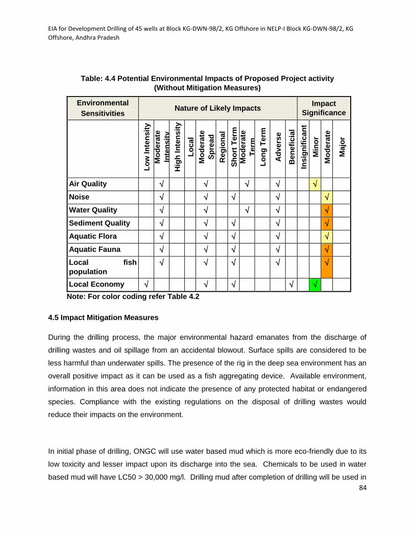
EIA for Development Drilling of 45 wells at Block KG-DWN-98/2, KG Offshore in NELP-I Block KG-DWN-98/2, KG
Offshore, Andhra Pradesh
84
Table: 4.4 Potential Environmental Impacts of Proposed Project activity
(Without Mitigation Measures)
Environmental
Sensitivities Nature of Likely Impacts
Impact
Significance
L
ow
In
ten
sit
y
Mo
de
rate
Inte
nsit
y
Hig
h I
nte
ns
ity
Lo
cal
Mo
de
rate
Sp
read
Re
gio
na
l
Sh
ort
Term
M
od
era
te
Term
Lo
ng
Term
Ad
ve
rse
Be
ne
fic
ial
Insig
nif
ican
t
Min
or
Mo
de
rate
Ma
jor
Air Quality
Noise
Water Quality
Sediment Quality
Aquatic Flora
Aquatic Fauna
Local fish
population
Local Economy
Note: For color coding refer Table 4.2
4.5 Impact Mitigation Measures
During the drilling process, the major environmental hazard emanates from the discharge of
drilling wastes and oil spillage from an accidental blowout. Surface spills are considered to be
less harmful than underwater spills. The presence of the rig in the deep sea environment has an
overall positive impact as it can be used as a fish aggregating device. Available environment,
information in this area does not indicate the presence of any protected habitat or endangered
species. Compliance with the existing regulations on the disposal of drilling wastes would
reduce their impacts on the environment.
In initial phase of drilling, ONGC will use water based mud which is more eco-friendly due to its
low toxicity and lesser impact upon its discharge into the sea. Chemicals to be used in water
based mud will have LC50 > 30,000 mg/l. Drilling mud after completion of drilling will be used in

EIA for Development Drilling of 45 wells at Block KG-DWN-98/2, KG Offshore in NELP-I Block KG-DWN-98/2, KG
Offshore, Andhra Pradesh
85
drilling operations at other locations. Bulk discharges of drilling fluids are prohibited in offshore
except in emergency situations. Synthetic Oil Based Mud (SOBM) is used to mitigate the
specific hole problems. The SOBM will have low toxicity and meet LC50 > 30,000 mg/l as per
mysid toxicity test or toxicity test conducted on locally available sensitive species. The chemical
additives (mainly organic constituents) used in the preparation of drilling fluid are bio-
degradable. Therefore, impact on biological environment will be minimal.
Drill cuttings generated in the drilling process are naturally occurring earth materials comprising
of chips of sandstone, shale, sand and lumps of clay. Their discharges do not cause significant
impact on marine water column as they settle down to the sea bottom and will not form heaps
due to higher water depths and strong currents. Traces of WBM / SOBM coated on drill cuttings
generally disperse in the water column causing temporary little increase in turbidity in the area
of release.
The domestic waste discharges such as galley wastewater and sewage generated in the drilling
rig increase in turbidity in the water column temporarily. Chlorination is done before discharge.
However, drilling rigs has domestic sewage treatment facilities for waste generated from
accommodation areas and the effluent released to the sea will meet standards prescribed by
MARPOL.
Some quantity of waste oil generated from the machinery of the drilling rig is of concern for its
disposal. Any disposal of waste oil into the sea is prohibited as per Merchant Shipping Act as
well as Environment Protection Act and all oily discharges will be treated to the required
standard. The spent oil will be brought to shore and disposed to authorized recyclers.
Various types of solid wastes are generated on drilling rigs from accommodation area and
process operations. Apart from being aesthetically undesirable, some wastes such as plastic
are not biodegradable and accumulate on the sea floor when released to the sea, causing
nuisance to benthic organisms. These wastes are not allowed to be disposed at sea. The food
wastes from the kitchen, degradable materials like paper etc. however, form food for marine
biota, hence allowed to be discharged in the sea. The impact of drilling operations on fisheries
or fishing activities is considered insignificant as these blocks are 28-250 km away from the
coast.

EIA for Development Drilling of 45 wells at Block KG-DWN-98/2, KG Offshore in NELP-I Block KG-DWN-98/2, KG
Offshore, Andhra Pradesh
86
4.5.1 Air Environment
Offshore receptors such as fishing vessels and commercial shipping are unlikely to be exposed
to poor quality air other than for very short durations, for example if sailing very close and
downwind of the site during flaring.
Mitigation of air emission impacts is done through:
Good operational controls and high level of monitoring shall be built into the design
operational aspects of the project.
Regular maintenance of engines and generators shall be done to keep the
environment impact minimum.
Existing and the proposed DG Sets will comply with the applicable emission norms.
Scrubbers will be provided to minimize the emissions and to maintain the emissions
within the prescribed limits.
Regular monitoring of emissions (from all DG Sets) and ambient air quality will be
carried out as per norms.
Emissions during transportation shall be minimized by ensuring regular maintenance
of the vessels.
Stack height shall be maintained to the optimum levels
4.5.2 Water Environment
Bulk discharge of drilling fluid in offshore is prohibited except in emergency situations.
Water Based Mud WBM will be recycled to the maximum extent. Unusable portion of
WBM will be discharged offshore into sea intermittently, at an average rate of 50 bbl/hr
as per G.S.R. 546 (E), dated 30/08/05, so as to have proper dilution and dispersion
without any adverse impact on marine environment.
Use of only low toxicity chemicals shall be ensured on board.
Sewage will be treated on-board of the rig as per MARPOL regulations. Residual
chlorine of the treated sewage shall not exceed 1mg/L before disposal.
Oily wastewater from deck washing, drainage system, bilges etc will be treated using on
board oil traps and will be disposed to sea as per norms laid by CPCB/APPCB.

EIA for Development Drilling of 45 wells at Block KG-DWN-98/2, KG Offshore in NELP-I Block KG-DWN-98/2, KG
Offshore, Andhra Pradesh
87
According to MARPOL regulations the discharge of oil content (without dilution) into sea
shall not exceed 15 ppm.
Adequate well management shall be ensured during well completion activities to
minimize produced water production.
Oil drilling operators shall maintain daily record of discharge of drill cutting & drill fluid to
offshore and also to monitor daily the effluent quality.
In case of oily cuttings, they will be transported on shore for appropriate disposal.
4.5.3 Impact on Biota
All precautionary measures shall be adopted to minimise disturbance to the marine animals due
to deployment and operations of offshore wells. The baseline information on existing marine
species in the area shall be obtained from state/district/regional level authorities and other
sources in an effort to reduce the potential adverse impacts of the project and future activities on
marine species.
4.5.4 Occupational Health Hazards from Noise Pollution
Site workers working near high noise equipment will use personal protective equipment to
minimise their exposure to high noise levels. Good working practices will be implemented to
reduce noise impact on the health and environment.
4.5.5 Noise Impacts due to Drilling Activities
Mobile noise sources such as rig and vessels shall be routed in such a way that
there is minimum disturbance to receptors.
Avoid loud, sudden noises, wherever possible. Integral noise shielding shall be used
where practicable and applicable.
Rubber padding/noise isolators shall be provided at equipment/machinery used
during the project activities.
Regular maintenance of all equipment and transportation vessels shall be ensured.
Idling of vessels or equipment shall be avoided when not in use.

EIA for Development Drilling of 45 wells at Block KG-DWN-98/2, KG Offshore in NELP-I Block KG-DWN-98/2, KG
Offshore, Andhra Pradesh
88
4.5.6 Waste Generation and Management
The site would develop and adopt proper system for the management, storage and disposal of
the hazardous and non-hazardous waste, for example measures such as:
Solid waste including domestic waste (from kitchen, gallery, laundries etc),
combustible and recyclable waste shall be collected, segregated and stored in
specified containers and shall be transferred to authorized contractors for their
disposal.
Hazardous waste such as medical waste, waste lube/system oil from machinery,
used oil from generator sets shall be handled as per Hazardous Wastes
(Management, Handling and Trans-boundary Movement) Rules, 2008. The waste will
be carefully stored in drums and transported to MoEF approved recyclers for its final
disposal. All precautions will be taken to avoid spillage from the storage.
Based on foregoing discussion on mitigation measures the impact matrix Fig: 4.4 & 4.5 on
comparision it may be noticed that preventive measures have contributed for the reduction of
impacts and risks due to drilling activities
Table:4.5 Potential Environmental Impacts of Proposed Project activity
(With Mitigation Measures)
Environmental
Sensitivities Nature of Likely Impacts
Impact
Significance
Lo
w In
ten
sit
y
Mo
dera
te
Inte
nsit
y
Hig
h In
ten
sit
y
Lo
cal
Mo
dera
te
Sp
read
Reg
ion
al
Sh
ort
Term
Mo
dera
te T
erm
Lo
ng
Term
Ad
vers
e
Ben
efi
cia
l
Insig
nif
ican
t
Min
or
Mo
dera
te
Majo
r
Air Quality
Noise
Water Quality

EIA for Development Drilling of 45 wells at Block KG-DWN-98/2, KG Offshore in NELP-I Block KG-DWN-98/2, KG
Offshore, Andhra Pradesh
89
Environmental
Sensitivities Nature of Likely Impacts
Impact
Significance
Sediment Quality
Aquatic Flora
Aquatic Fauna
Local fish
population
Local Economy
Note: For color coding refer Table 4.2
4.6 Response of Marine Ecosystems to Oil Spills.
The response of marine ecosystems to oil spills is given special consideration since oil spills are
identified as potentially most deleterious to the environment. Crude oil is a very hydrophobic
mixture and therefore does not mix well with water. When both mix, small oil droplets tend to
disperse into the aqueous phase. The large droplets quickly return to the surface oil slick while
the smaller droplets remain in the water. Some water is incorporated into the oil layer in the form
of water-in-oil emulsion. At the same time, its hydrophobic nature causes crude oil to be
adsorbed to particulate matter in seawater and to quickly sediment with it to the bottom.
Petroleum hydrocarbons associated with sediments are also known to be more persistent and to
cause more harm than hydrocarbons in the water column.
4.6.1 Resource Sensitivity Assessment.
The variability in season and geography related to physical-chemical attributes of the marine
environment affect all marine life. As a result, marine organisms may exhibit varying degrees of
ecological adaptation to changing conditions of their existence. With respect to oil spills, the
major concerns in biological resource sensitivity assessment were abundance, initial mortality,

EIA for Development Drilling of 45 wells at Block KG-DWN-98/2, KG Offshore in NELP-I Block KG-DWN-98/2, KG
Offshore, Andhra Pradesh
90
population perturbation, fate of survivors and potential for population recovery. The following
biological species within the open sea area are thus considered most sensitive to spilled oil.
Plankton: Some crude components are deleterious to a wide range of planktonic organisms.
However, they have a high recovery potential which reduces any significant impacts to their
populations. Impacts to plankton are usually limited to very transient effects in the vicinity of the
spill release point.
Fish: Adult fish exhibit avoidance behavior initiated by the smell of hydrocarbons. This reduces
the risk to them as a result of exposure to oil. The fish eggs and larvae on the other hand are a
lot more sensitive as single individuals.
Seabird: The most important factors in seabird damage evaluation are; abundance and
diversity, molting and migration patterns. While marine birds can suffer major damage from oil
spills in the near shore areas, diving birds are the most affected as they live on the surface of
the sea and dive for food. As they dive into floating oil they become covered in it. Also during
oiling plumage air is replaced by water causing reduced insulation and buoyancy. Migratory
birds may be less vulnerable due to absence at time of spill but non-migratory birds are hard hit
with the possibility of a colony facing elimination.
Marine Mammals: Contact of these mammals with oil could be injurious particularly during
breeding period.
Deep Sea Benthos: Long term studies at a number of oil spill sites where hydrocarbons have
remained in the sediments have shown amongst others, effects from residue accumulation on
behavior in certain benthic species. The effect on benthic communities covers a small area and
damage is reversible if contamination stops. Several studies of oil spills in different parts of the
world show that different environments have different recovery rates. Generally, open water oil
spills are not known to cause excessive adverse effects on water column organisms. Hence the
open waters are not considered a sensitive habitat. The effect of oil spilled at sea may be
substantial during the spill, but recovery is very rapid and after effects minimal. This is further
confirmed by the results of the oil spill drift and weathering simulations which predict substantial
evaporation of the oil spilled at sea within a relatively short time
.
EIA for Development Drilling of 45 wells at Block KG-DWN-98/2, KG Offshore in NELP-I Block KG-DWN-98/2, KG
Offshore, Andhra Pradesh
91
Sensitivity of Coastal Communities: Deep water drilling locations as proposed in this project
are 28-350 km away from the east coast of India. Impact of oil spill on coastal communities will
be minimal if oil spill contingency plan is activated in time prevent its spread.
Fire and Explosion: Where there is appropriate source of heat and fuel, there is a potential for
fire outbreak. Thus, drilling activities have a high potential for fire outbreak.
4.7 Summary of Environmental Impacts
Environmental aspect, impact, management plan and monitoring for deep water drilling
operations has been summarized in the Table:4.6.
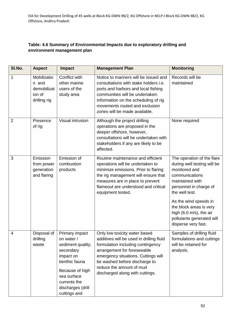
EIA for Development Drilling of 45 wells at Block KG-DWN-98/2, KG Offshore in NELP-I Block KG-DWN-98/2, KG
Offshore, Andhra Pradesh
92
Table: 4.6 Summary of Environmental Impacts due to exploratory drilling and
environment management plan
Sl.No. Aspect Impact Management Plan Monitoring
1 Mobilizatio
n and
demobilizat
ion of
drilling rig
Conflict with
other marine
users of the
study area
Notice to mariners will be issued and
consultations with stake holders i.e.
ports and harbors and local fishing
communities will be undertaken.
Information on the scheduling of rig
movements routed and exclusion
zones will be made available.
Records will be
maintained
2 Presence
of rig
Visual intrusion Although the project drilling
operations are proposed in the
deeper offshore, however,
consultations will be undertaken with
stakeholders if any are likely to be
affected.
None required
3 Emission
from power
generation
and flaring
Emission of
combustion
products
Routine maintenance and efficient
operations will be undertaken to
minimize emissions. Prior to flaring
the rig management will ensure that
measures are in place to prevent
flameout are understood and critical
equipment tested.
The operation of the flare
during well testing will be
monitored and
communications
maintained with
personnel in charge of
the well test.
As the wind speeds in
the block areas is very
high (6.0 m/s), the air
pollutants generated will
disperse very fast.
4 Disposal of
drilling
waste
Primary impact
on water /
sediment quality,
secondary
impact on
benthic fauna
Because of high
sea surface
currents the
discharges (drill
cuttings and
Only low toxicity water based
additives will be used in drilling fluid
formulation including contingency
arrangement for foreseeable
emergency situations. Cuttings will
be washed before discharge to
reduce the amount of mud
discharged along with cuttings.
Samples of drilling fluid
formulations and cuttings
will be retained for
analysis.
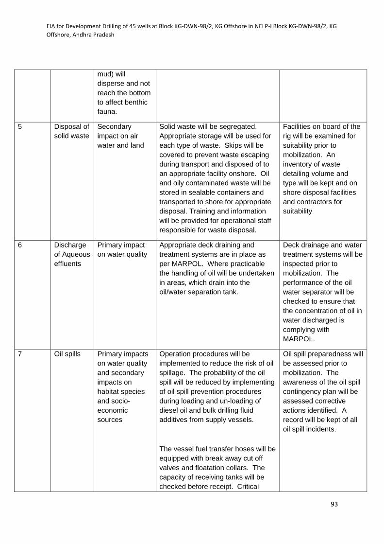
EIA for Development Drilling of 45 wells at Block KG-DWN-98/2, KG Offshore in NELP-I Block KG-DWN-98/2, KG
Offshore, Andhra Pradesh
93
mud) will
disperse and not
reach the bottom
to affect benthic
fauna.
5 Disposal of
solid waste
Secondary
impact on air
water and land
Solid waste will be segregated.
Appropriate storage will be used for
each type of waste. Skips will be
covered to prevent waste escaping
during transport and disposed of to
an appropriate facility onshore. Oil
and oily contaminated waste will be
stored in sealable containers and
transported to shore for appropriate
disposal. Training and information
will be provided for operational staff
responsible for waste disposal.
Facilities on board of the
rig will be examined for
suitability prior to
mobilization. An
inventory of waste
detailing volume and
type will be kept and on
shore disposal facilities
and contractors for
suitability
6 Discharge
of Aqueous
effluents
Primary impact
on water quality
Appropriate deck draining and
treatment systems are in place as
per MARPOL. Where practicable
the handling of oil will be undertaken
in areas, which drain into the
oil/water separation tank.
Deck drainage and water
treatment systems will be
inspected prior to
mobilization. The
performance of the oil
water separator will be
checked to ensure that
the concentration of oil in
water discharged is
complying with
MARPOL.
7 Oil spills Primary impacts
on water quality
and secondary
impacts on
habitat species
and socio-
economic
sources
Operation procedures will be
implemented to reduce the risk of oil
spillage. The probability of the oil
spill will be reduced by implementing
of oil spill prevention procedures
during loading and un-loading of
diesel oil and bulk drilling fluid
additives from supply vessels.
The vessel fuel transfer hoses will be
equipped with break away cut off
valves and floatation collars. The
capacity of receiving tanks will be
checked before receipt. Critical
Oil spill preparedness will
be assessed prior to
mobilization. The
awareness of the oil spill
contingency plan will be
assessed corrective
actions identified. A
record will be kept of all
oil spill incidents.

EIA for Development Drilling of 45 wells at Block KG-DWN-98/2, KG Offshore in NELP-I Block KG-DWN-98/2, KG
Offshore, Andhra Pradesh
94
equipment i.e hoses and gauges will
be maintained.
Provisions of appropriate equipment,
implementation of oil spill response
measures and training of personnel
will be ensured.
Equipment maintenance is important
in the prevention of blowouts and
specific. Oil spill response
arrangements are detailed in Oil spill
Response Plan.
8 Blow out Primary impact
on air and water
quality and
secondary
impact on marine
species.
Blow out contingency plan
Oil spill contingency plan
Regular BOP function
check and maintenance
of hydraulic activator.
Regular mud parameters
check for density
changes.

EIA for Development Drilling of 45 wells at Block KG-DWN-98/2, KG Offshore in NELP-I Block KG-DWN-98/2, KG
Offshore, Andhra Pradesh
95
CHAPTER-5
Environment Management Plan
Offshore drilling operations may interact with marine environment and result in physical,
chemical and biological changes. Impacts of these changes are to be mitigated by adopting
industry specific standards, guidelines and prevailing regulatory requirements.
Environmental monitoring helps in detecting changes in the environment resulting from
discharges from oil & gas drilling operations, Environment Management Plan provides a
delivery mechanism to address the adverse environmental impact of a project during its
execution. It aims at mitigating potential impacts associated with exploratory drilling activity
based on baseline data. To develop EMP, the effects of the following due to offshore
exploratory drilling and contingency plans to mitigate / avoid these impacts are described in
this chapter.
1. Physical presence of drilling rig and movement of associated vessels
(MSV/OSV)
2. Emissions and discharges from actual drilling operations
3. Blowout and Oil spill combatment
4. Occupational Hazards
5. H2S emission
5.1 Physical Presence of drilling rig and Movement of Vessels
The drilling rig and associated MSV/OSV’s may cause disruption to marine traffic and fishing
during mobilization and de-mobilization. To prevent this, ONGC issues notice to concerned
authorities / marine users. Consultations are held with the Ports and Harbor authorities and
local fishing communities about ONGC’s operations. Information on the scheduling of the rig
movements, routes, exclusion zones and durations are furnished. Any change in the
program is informed well in advance to the concerned authorities. Proper records of
consultations are maintained.
EIA for Development Drilling of 45 wells at Block KG-DWN-98/2, KG Offshore in NELP-I Block KG-DWN-98/2, KG
Offshore, Andhra Pradesh
96
5.2 Emissions and Discharges from Drilling Operations
5.2.1 Atmospheric Emissions:
Burning of HSD for generating power for the drilling operation results in atmospheric
emission of SO2, NOx, CO, particulates and possibly hydrocarbons. Emissions from diesel
gensets (SO2, NOx, CO, Particulates and possibly hydrocarbons) are likely to occur.
However, with the prevailing wind speeds in open sea the dispersion of air pollutants will be
very high and will not accumulate in the vicinity of the working area of the rig. Measures to
ensure minimal impacts include:
Adequate stack height of the DG sets and its placement at safe distance from
working area
Appropriate management of power generation
Use of low Sulphur diesel oil (185 ppm Sulphur content)
Fugitive emissions of VOC’s from diesel fuel to be reduced by appropriate
Storage and handling
5.2.2 Noise levels and Noise abatement
Noise levels will generally remain in permissible limits within short distance from the source.
However, the following mitigation measures are followed;
Acoustic enclosures for all generators
Exhausts are provided with silencers
Operators / personnel working near the high noise source at the rig shall be
Provide with earmuffs and earplugs etc.
Deployment of drilling crew in high noise area for short duration.
5.2.3 Marine Discharges
The offshore drilling rig generates two major and four minor waste streams. These include
Major discharge
Unused Drilling fluid
Drill cuttings
Minor discharge

EIA for Development Drilling of 45 wells at Block KG-DWN-98/2, KG Offshore in NELP-I Block KG-DWN-98/2, KG
Offshore, Andhra Pradesh
97
Sanitary waste,
Domestic waste and
Well fluid and deck drainage
Drilling Fluids
Drilling fluids are mostly water based and in the event of specific hole problem synthetic oil
based mud (SOBM) are used in exploratory drilling to maintain hydrostatic pressure control
in the well and to lubricate the drill bit. Drilling fluid system is circulatory system and mud
coming out from the well is passed through solid control equipment and treated and re-
circulated into the well. Only small portion of the mud is wasted during drilling along with
cuttings and solid control equipment. Non-usable portion will be discharged intermittently (50
bbl/hr) in sea with proper dilution as per GSR 546 (E). SOBM will be not be discharged into
sea, completely recycled and reused after completion of the well it will be transported to the
new location.
Drill Cuttings
The drill cuttings removed from the well are rock debris and mineral particles generated by
drilling into the underground formation, are separated at shale shaker and washed
thoroughly before discharging to sea. Cuttings generated while drilling 36” & 17-1/2” hole
size will be discharged to sea bed whereas cuttings from 12-1/4” & 8-1/2” hole size will be
discharged to sea surface in a phased manner. Impact of cuttings along with associated
water based mud will be reduced significantly due to dilution effect and wave currents.
Proposed control measures for reducing the wastage of drilling mud and disposal of drill
cuttings include:
Efficient maintenance of solid control equipment to minimize mud waste.
Proper maintenance of valves / flanges of mud tanks and mud circulation
Systems to reduce risks of leaks.
Strict adherence to standard operational procedures of the rig.
Thoroughly washed drill cuttings separated from WBM / SOBM will be discharged into sea
intermittently at an average rate of 50 bbl/hr as per GSR 546 ( E) from the rig so as to have
proper dilution and dispersion without any adverse impact on marine environment. The water
depths in these block varies from 600 m to 2500 m therefore, the impact of disposal of drill
cuttings on sea bed will be minimal. If cuttings are found toxic, these will be brought to shore

EIA for Development Drilling of 45 wells at Block KG-DWN-98/2, KG Offshore in NELP-I Block KG-DWN-98/2, KG
Offshore, Andhra Pradesh
98
for safe disposal. Approximate quantities of cuttings that would be generated during drilling
of typical offshore well is given in Table- 6.1
Domestic waste
Kitchen waste is separated into bio-degradable and non-biodegradable components. Non-
biodegradable waste (plastic, glass and metal etc) is packed, labelled and sent to Base for
further safe disposal. The biodegradable garbage separated from other domestic wastes,
will be ground in a crushing machine and dumped overboard in biodegradable jute bags.
The other solid wastes will be collected, compacted and stored in containers or placed in
special metal baskets or plastic bags for transport to onshore.
Sanitary Waste
Sanitary waste is treated in the sewage treatment plants on board of the drilling rig and
disposed to sea after maintaining the required disposal parameters. Waste water generated
is expected to be approximately 20 M3 (0.22 m³/day/person grey water and 0.11 m³/Day /
person for Black water for 50-60 persons)
The following criteria are strictly followed before disposing to sea:
BOD5 : 50 mg/l or less
COD : 250 mg/l or less
Suspended solid : 30-40 mg/l or less
Coliform count : 200 /100 ml
Residual Chlorine : 1 PPM.
Well fluid and deck drainage
Produced water during well testing operation, deck floor washings and spent oil etc., are the
hazardous waste generated during the offshore drilling. Produced water which is generated
during production testing is treated in the produced water handling system where oil is
separated and water is disposed to sea after meeting the standards (oil content < 40 ppm).
Spent oil is collected, labeled and sent back to base for further safe disposal through
authorized recyclers. Deck drainage is collected and treated separately for oil removal by
gravity separation before discharge.

EIA for Development Drilling of 45 wells at Block KG-DWN-98/2, KG Offshore in NELP-I Block KG-DWN-98/2, KG
Offshore, Andhra Pradesh
99
5.3 Oil Spill Contingency Plan
During exploration and production of hydrocarbon oil and oil-based products are accidentally
spilled into sea. This poses risks to human health and environmental quality. Every effort
must be made to prevent oil spills and to clean them up quickly.
The entire offshore facilities are designed, installed and operated in such a way, so as to
minimize possibility of any oil spills. Facilities and resources supplied by outsourced
agencies also meet international pollution prevention design and operation standards. Oil
spill risks are identified and measures to prevent and contain oil spill have been outlined in
contingency plan given below;
To establish response procedures for oil spills
To combat, contain, recover, clean up and dispose off the spilled oil
To provide training and drill schedule for keeping the system in place, and
To meet statutory requirements.
Activation of plan starts with notification of “Oil spill” and spill assessment. Immediate action
is taken to disconnect the source. Further action is taken based on Short Term and Long
Term strategies for spill combatment.
Strategy during First six Hours:
Depending upon nature of emergency at sea and weather conditions booms will be laid
around source of spill for containment. Recovered oil will be stored for further disposal as
per laid down procedures.
If some quantity of oil has spread prior to deployment of booms or some oil has slipped away
during containment and recovery process, following factors will be taken into consideration
prior to taking decision on application of dispersant:
a) Spilled oil shall not be more than 4 hours old.
b) Oil is moving towards shoreline.
c) Spilled crude characteristics are amenable to use of dispersants.
EIA for Development Drilling of 45 wells at Block KG-DWN-98/2, KG Offshore in NELP-I Block KG-DWN-98/2, KG
Offshore, Andhra Pradesh
100
d) Prevailing weather conditions are conducive to dispersant applications.
Prior approval from Coast Guard for use of dispersant will be obtained.
Spraying of Dispersants:
During rough weather, monsoon, low visibility or in case of delayed deployment of
equipment, the spraying of dispersants is considered one of the options, because this
strategy needs very less reaction time (resource mobilization time) and can be initiated by
the boat /vessels crew operating in that area. Spray of dispersants can be done through
Helicopters also. Response equipment such as Containment Booms will be deployed for
protection of Godavari river estuary, mangroves, shrimp farms and other sensitive areas
such as river mouths to deflect spills towards other areas of the shoreline where it shall
cause less harm to the environment.
Shore Cleanup
Despite best efforts to contain and recover spilled oil, there is always a likelihood of spilled
oil reaching shorelines. Shoreline cleanup technique will be practiced for the left over oil as
per topography of the coastline.
Monsoon Conditions (South West and North East)
Day Time Operations: In SW monsoon, especially in the month of May & June, the sea
conditions are pretty rough, winds are strong, heavy rainfall reduces the visibility, and
operations of smaller vessels becomes difficult. Observation / tracking of oil slick become
much more difficult and hence, deployment of Oil Spill Response Equipment will become
difficult and unsafe for men to work from small boats. Cyclonic weather would further hamper
the operations.
Night Time: During night time the visibility further goes down and the problem is
compounded when it starts raining or weather becomes cyclonic. In this situation keeping
the track of oil spill and conduct of safe operations becomes very difficult.
Strategy for Offshore Zones
Strategy for Offshore Zones
The strategies for responding to Offshore Oil Spills are as follows;
EIA for Development Drilling of 45 wells at Block KG-DWN-98/2, KG Offshore in NELP-I Block KG-DWN-98/2, KG
Offshore, Andhra Pradesh
101
a) Monitor and Evaluate: If the oil spill is not approaching coast speedily, it is to be
monitored continuously by boats/vessels operating in that area, or by helicopter, as the
situation demands. The Emergency Control Room (ECR) shall start plotting the position and
monitoring the oil slick every 15–30 minutes or as directed. The ECR would study the inputs
received from various sources, evaluate the size of oil spill and declare it as minor or major
oil spill or as Tier 1, Tier 2 or Tier 3 level type. PRP/Dispersant Spraying shall also predict
the fate of spilled oil and action to be initiated.
b) Containment and Recovery: If weather is favorable and response action can begin in
time, the spilled oil will be collected with the help of booms and skimmers and are sent to
CPCB accredited waste oil recyclers.
c) Dispersant Spraying: If the spill is moving away from the coast, dispersant spraying may
be commenced by the vessels operating in that area. If the oil spill is of higher magnitude the
ECR may decide for containment and recovery operation. Use of dispersants spraying may
also be under taken if the oil slick is moving towards the shore with very slow speed and
some reaction time is available for OSR Team for preparation of containment and recovery
operations ashore. Coast Guard guidelines will be adhered to, during decision making on
dispersant application.
As a strategy using dispersants means using chemicals to enhance the process of natural
dispersion, but due care shall be taken by getting the water samples analyzed at frequent
intervals so as to determine the limit of use of dispersant in those waters. NOSDCP of Coast
Guard also provides guide lines about the use of dispersants.
5.4 Occupational Health
Occupational hazards associated with offshore drilling include illness from exposure to
geographical and climatic elements. Work in offshore can involve exposure to hazardous
substances, noise, vibrations, hot or cold conditions, heavy manual handling activity on the
derrick floor etc. Drilling rigs especially in deep water drilling are isolated, workforce travels
to work by helicopter and perform shift duties. Extended long distance travelling,
psychological stress resulting from physical isolation due to remoteness of site and shift duty
pattern, sea sickness and exposure to extreme weather conditions are other hazards.
Harsh climate, parasitic diseases and infections may result in respiratory tract diseases.
EIA for Development Drilling of 45 wells at Block KG-DWN-98/2, KG Offshore in NELP-I Block KG-DWN-98/2, KG
Offshore, Andhra Pradesh
102
On board qualified doctor is available 24 hrs. on the drilling rig for the immediate treatment
and first aid. For serious injuries and diseases patient is evacuated by the emergency
Helicopter exclusively meant for emergencies to the nearest base.
Occupational Health Hazards
Occupational health hazards identified during drilling operation are given below:
Chemical Hazards
Noise Hazards
Radiation Hazards
Illumination Hazards
Vibration Hazards
Temperature Extremes
Biological Hazards
Ergonomic Hazards
Stress related Hazards
Health Hazard Control is done by adopting following measures
Prioritize the health hazards based on their risk potential.
Identify specific work groups affected by each hazard.
Determine the controls required to manage these identified hazards. The cost of
each identified control versus benefits of its implementation may be evaluated.
Develop an action plan identifying work to be done
The health and hygiene of the personnel working at the Drilling Rig will be monitored through
periodic health checks of the persons. All employees undergo a periodic medical
examination (PME). The record of the health checkup will be maintained centrally off site in
confidential file by the medical section. The medical officer at base recommends appropriate
treatment for the persons found to be having any health problems requiring attention.
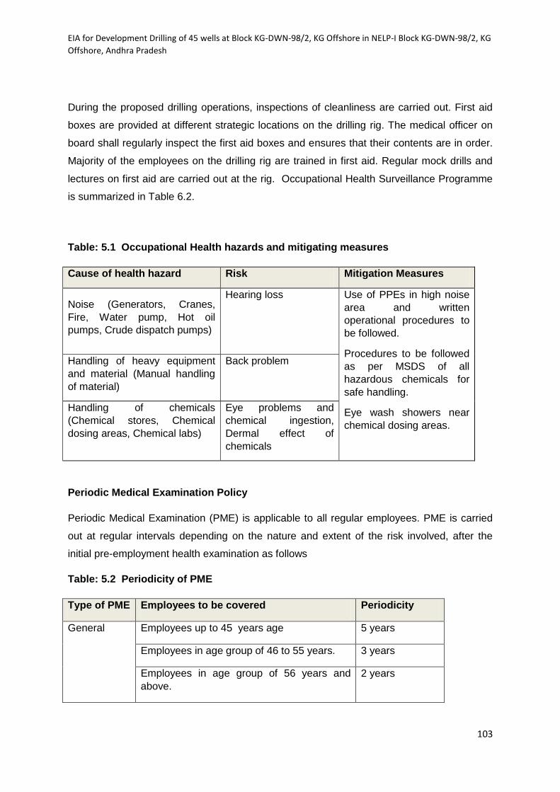
EIA for Development Drilling of 45 wells at Block KG-DWN-98/2, KG Offshore in NELP-I Block KG-DWN-98/2, KG
Offshore, Andhra Pradesh
103
During the proposed drilling operations, inspections of cleanliness are carried out. First aid
boxes are provided at different strategic locations on the drilling rig. The medical officer on
board shall regularly inspect the first aid boxes and ensures that their contents are in order.
Majority of the employees on the drilling rig are trained in first aid. Regular mock drills and
lectures on first aid are carried out at the rig. Occupational Health Surveillance Programme
is summarized in Table 6.2.
Table: 5.1 Occupational Health hazards and mitigating measures
Cause of health hazard Risk Mitigation Measures
Noise (Generators, Cranes,
Fire, Water pump, Hot oil
pumps, Crude dispatch pumps)
Hearing loss Use of PPEs in high noise
area and written
operational procedures to
be followed.
Procedures to be followed
as per MSDS of all
hazardous chemicals for
safe handling.
Eye wash showers near
chemical dosing areas.
Handling of heavy equipment
and material (Manual handling
of material)
Back problem
Handling of chemicals
(Chemical stores, Chemical
dosing areas, Chemical labs)
Eye problems and
chemical ingestion,
Dermal effect of
chemicals
Periodic Medical Examination Policy
Periodic Medical Examination (PME) is applicable to all regular employees. PME is carried
out at regular intervals depending on the nature and extent of the risk involved, after the
initial pre-employment health examination as follows
Table: 5.2 Periodicity of PME
Type of PME Employees to be covered Periodicity
General Employees up to 45 years age 5 years
Employees in age group of 46 to 55 years. 3 years
Employees in age group of 56 years and
above.
2 years

EIA for Development Drilling of 45 wells at Block KG-DWN-98/2, KG Offshore in NELP-I Block KG-DWN-98/2, KG
Offshore, Andhra Pradesh
104
Specific Employees having hazard based profiles As per
requirement
Random On need basis- Up to 10 % of employees
examined.
Every year
PME is conducted at accredited laboratories.
5.5 H2S Protection in Drilling Operations
H2S is not expected in this field. However being the exploratory nature of the drilling the
following control measures will be taken if presence of H2S is detected any time of drilling.
H2S Detection System Presence
A four channel H2S gas detection system will be provided. Sensors will be positioned at
optimum points for detection, actual locations being decided onsite but likely to be: Well
Nipple, Rig flour, Shaker Header tank and Substructure cellar pit:
The detection system will be connected to an audio visual (siren and lights) alarm system.
The two levels of alarm are as follows:
10 ppm H2S low level alarm triggers a light signal but does not indicate danger for all.
Persons are required to stand by to check the installation after announcement on
public address system (PA) by the tool pusher, otherwise, to proceed to the upwind
side.
20 ppm H2S high level triggers a sound alarm and also red light on the control panel.
Emergency alarm is sounded by two short rings of bell intermittently. This requires
breathing equipment to be used immediately and the hazard area to be vacated
unless announcement on Public Address System (PA) by the tool pusher provides
other instructions.
The mud logging will have a completely independent detection system which is connected to
an alarm in the cabin. This system will be adjusted to sound an alarm at a concentration
level of 10 ppm as suggested in the Drilling and Production Safety code for onshore
operations issued by the Institute of Petroleum.
A stock of H2S scavenger will be kept at drilling site for emergency use.
EIA for Development Drilling of 45 wells at Block KG-DWN-98/2, KG Offshore in NELP-I Block KG-DWN-98/2, KG
Offshore, Andhra Pradesh
105
Visual Warning Signs
In case of high level H2S alarm, the following warning signs will be displayed to alert
helicopter and vessels in the vicinity of the drilling rig.
Red flag 90cm X 60 cms on each side of the rig.
Danger boards painted yellow with black lettering 30 cms high indicating "DANGER
H2S".
Muster stations and escape routes
Since H2S is heavier than air, it is likely to settle down at lower levels particularly in
still air or in light winds and cut off the natural escape route to the boat landing; this
situation gives rise to the following requirements:
Sufficient stair cases on the upwind side of prevailing winds for escape route up the
stairs or down to the lifeboat.
Muster stations for operating personnel in the event of gas alarm, areas in the open
on the upper deck which can be kept free of H2S by the wind.
Ventilation
Forced air ventilation to disperse any accumulation of H2S will be provided by fans (bug
blower) at the following points:
Shale shaker
Mud tanks
Derrick floor
If higher levels of H2S >10 ppm are found following steps will be taken.
Driller will shut down rotary and pumps pickup so that drill pipe in BOP and chain
down the break.
One pre-assigned rough neck will go to doghouse and put on breathing apparatus.
All other rig personnel will evacuate the rig and move in up-wind direction to
designated muster point.
Driller and rough neck will return to the rig floor and commence circulating H2S
scavenger slowly and reciprocating pipe.

EIA for Development Drilling of 45 wells at Block KG-DWN-98/2, KG Offshore in NELP-I Block KG-DWN-98/2, KG
Offshore, Andhra Pradesh
106
The level of H2S will be checked in all work areas. H2S scavenger will be added to
the mud and circulated. If H2S levels drop, drilling will be continued with scavenger-I
the mud. Approximately 30% of hydrogen peroxide (H2O2) solution will neutralize
H2S gas in the mud at 20 gallons of H2O2 per 100 barrels of mud.
The workers will be provided with personal H2S detectors along with self-containing
breathing apparatus.
Control measures
H2S will cause a sudden drop of mud pH. The mud man will therefore organize and
supervise continuous pH checks while drilling. Checks should be as frequent as possible
and always made following a formation change.
Following control measures will be taken in case of small levels of H2S detection.
H2S scavenger will be added to mud
H2S levels will be checked at regular intervals for possible increase
All personnel of the rig will be informed about the presence of H2S and current wind
direction
Operation will be commenced in pairs
Sub base and cellar out of bounds will be rendered without further checking levels in
this area
The workers will be provided with personal H2S detectors along with SCBA.
H2S Kick control
The control of H2S kick may be achieved either by bulldozing gas back into formation or
circulating it out. The actual method to be adopted will depend upon the condition of the
well. When a gas kick occurs, estimate the quantity of H2S present taking adequate
precautionary measures of wearing self-contained breathing apparatus (SCBA). The
following procedure will be adopted:
Close BOP, monitor SIDPP, SICP & pit gain.
If the concentration is high and cannot be circulated out due to H2S hazard in
atmosphere, bulldoze the gas into formation by pumping through kill line.
Raise mud wt. and pH as required.

EIA for Development Drilling of 45 wells at Block KG-DWN-98/2, KG Offshore in NELP-I Block KG-DWN-98/2, KG
Offshore, Andhra Pradesh
107
Load H2S scavenger like zinc carbonate and ironite sponge as may be
necessary in the active mud pit.
Circulate the gas through choke and degasser and burn off the gas.
The following factors will also be kept in view:
All persons on the drilling floor, shale shaker area, mud pump and tank should put on
self-contained breathing apparatus when the kick is to be circulated out.
Persons who are not required for the control operation will be withdrawn to a safe
area, where adequate ventilation is arranged.
Frequent checks with portable H2S gas detector will be made.
Supply vessels (in case of Offshore) should stay upwind on power and maintain
continuous radio and visual watch.
5.6 Summary of Environmental Management Plan
Marine Environment
Low toxicity WBM, having 96 h LC50 > 30000 mg/l will be used
The water based drilling muds will be re-cycled and reused to maximum extent.
Drill cuttings, thoroughly washed and separated from WBM, will be discharged to the sea
intermittently as per GSR546 ( E ).
In order to mitigate the specific hole problem, Synthetic oil based mud(SOBM) with low
toxicity of 96 h LC50 > 30,000 mg/l as per mysid toxicity test or toxicity test conducted on
locally available sensitive species will be used.
Waste water generated on drilling rigs is treated as per MARPOL and CPCB guidelines,
before disposal to the sea. Modular treatment plants are available for on board to treat
domestic wastewater.
As discharge of waste oil into the sea is prohibited, oily wastes is collected and sent to
base for disposal.
Emissions from DG sets are controlled through efficient maintenance and stack heights.
Barite in drilling fluids contains < 1 mg/kg Mercury and < 3 mg/kg Cadmium.
The biodegradable garbage separated from other domestic wastes, is grounded in a
crushing machine, filled into Jute bags and discharged in sea. The non-biodegradable
solid wastes is collected, compacted and stored in containers, or placed in special metal
baskets or plastic bags for transport to onshore facilities.

EIA for Development Drilling of 45 wells at Block KG-DWN-98/2, KG Offshore in NELP-I Block KG-DWN-98/2, KG
Offshore, Andhra Pradesh
108
Sewage is treated at the facilities available at the rig and chlorination of treated sewage
is done to achieve 1 mg/l residual chlorine before discharging into sea.
The left over drilling fluids after drilling is completed will be transported next site for
reuse. SOBM mud is always recycled and not discharged in to sea whereas only non-
usable WBM is occasionally discharged into sea with proper dilution as per guidelines.
Based on risk assessment studies it is suggested that during drilling activity, fishing
should be restricted to 500 m zone from the drilling locations.
Oil spill contingency plan exists to combat any accidental spills or blowout
Air Environment
All equipments would be operated within specified design parameters during drilling
operations.
The DG set emissions meet standards stipulated by CPCB.
Any dry, dusty materials (chemicals), mud etc. are stored in bags or sealed containers.
Quantity of flared gas during well testing is kept minimum and restricted to the short
duration.
H2S detection system will be installed at optimum points for detection like: Well Nipple,
Rig flour, Shaker Header tank and Substructure cellar pit.
Noise Environment
Noise barriers / shields are provided around the high noise units wherever possible.
Use of ear muffs / plugs and other protective devices are provided to the workforce.
Acoustic enclosures around high noise sources are provided depending on the size
of the unit.