ehd-scm-series-machine-vision-cameras-manual · ehd imaging gmbh scm‐series user manual for...
TRANSCRIPT

2019
EHD imaging GmbH
27.11.2019
EHD SCM-TR Serie Manual

EHD imaging GmbH SCM‐Series User Manual for Machine Vision Cameras
Contents
1 Introduction to ToupCam Machine Vision Cameras .......................................................... 1
1.1 Product description .................................................................................................................... 1
1.2 Characteristics ............................................................................................................................ 1
1.3 IUA series camera specifications ............................................................................................... 1
1.4 IUB series camera specifications ............................................................................................... 2
1.5 IUC series camera specifications ............................................................................................... 2
1.6 IUA series technical specifications ............................................................................................ 3
1.6.1 SCM432-M-TR(Art. IUA1700KMA) ................................................................................................ 3
1.6.2 SCM432-C-TR (Art. IUA1700KPA) ................................................................................................... 5
1.6.3 SCM178-M-TR (Art. IUA6300KMA) ................................................................................................ 7
1.6.4 SCM178-C-TR (Art. IUA6300KPA) ................................................................................................... 9
1.6.5 SCM428-M-TR (Art. IUA7100KMA) .............................................................................................. 11
1.6.6 SCM428-C-TR (Art. IUA7100KPA) ................................................................................................. 13
1.6.7 SCM183-M-TR (Art. IUA20000KMA) ............................................................................................ 15
1.6.8 SCM183-C-TR (Art. IUA20000KPA) ............................................................................................... 17
1.7 IUB series technical specifications .......................................................................................... 19 1.7.1 SCM2020-M-TR (Art. IUB4200KMA) ............................................................................................ 19
1.7.2 SCM2020-UV-TR (Art. IUB4200KMB) ........................................................................................... 21
1.7.3 SCM0806-M-TR (Art. IUB43000KMA) .......................................................................................... 23
1.8 IUC series technical specifications .......................................................................................... 25 1.8.1 SCM571-C-TR (Art. IUC26000KPA) ............................................................................................... 25
1.8.2 SCM342-M-TR (Art. IUC31000KMA) ............................................................................................ 27
1.8.3 SCM342-C-TR (Art. IUC31000KPA) ............................................................................................... 29
1.8.4 SCM455-M-TR (Art. IUC60000KMA) ............................................................................................ 31
1.8.5 SCM455-C-TR (Art. IUC60000KPA) ............................................................................................... 33
2 Camera Dimension and Interface....................................................................................... 35
2.1 IUA series camera dimensions and outputs ............................................................................ 35 2.1.1 IUA series camera mechanical housing dimensions .............................................................................. 35
2.1.2 IUA series camera interface ................................................................................................................... 36
2.1.3 IUA series camera power supply and I/O connector ............................................................................. 36
2.1.4 IUA series camera packing information ................................................................................................ 36
2.2 IUB series camera dimensions and outputs ............................................................................ 37 2.2.1 IUB series camera mechanical housing dimensions .............................................................................. 37
2.2.2 IUB series camera interface ................................................................................................................... 38

EHD imaging GmbH SCM‐Series User Manual for Machine Vision Cameras
2.2.3 IUB series camera power supply and I/O connector ............................................................................. 38
2.2.4 IUB series camera packing information ................................................................................................ 39
2.3 IUC series camera dimensions and outputs ........................................................................... 40 2.3.1 IUC series camera mechanical housing dimensions .............................................................................. 40
2.3.2 IUC series camera interface ................................................................................................................... 41
2.3.3 IUC series camera power supply and I/O connector ............................................................................. 41
2.3.4 IUC series camera packing information ................................................................................................ 42
3 Description of Software Development ................................................................................ 43
3.1 SDK introduction ...................................................................................................................... 43 3.1.1 SDK support platform ........................................................................................................................... 43
3.1.2 SDK content brief introduction ............................................................................................................. 43
3.2 Client democpp description ..................................................................................................... 45
3.3 EHDView UI description .......................................................................................................... 45
4 Camera Installation and Operation ................................................................................... 48
4.1 Installation steps ....................................................................................................................... 48
4.2 Driver check .............................................................................................................................. 48
4.3 Setup and operation .................................................................................................................. 48
5 Main Features of democpp .................................................................................................. 50
5.1 Description of main features .................................................................................................... 50
5.2 Image format and frame rate .................................................................................................. 50 5.2.1 Camera data format ............................................................................................................................... 50
5.2.2 Frame rate .............................................................................................................................................. 51
5.2.3 Area of interest setup ............................................................................................................................. 52
5.3 Global Shutter and Rolling Shutter ........................................................................................ 52 5.3.1 Global Shutter ........................................................................................................................................ 52
5.3.2 Rolling Shutter ....................................................................................................................................... 53
5.4 Image acquisition and transmission ........................................................................................ 53 5.4.1 Free run mode ........................................................................................................................................ 54
5.4.2 Trigger mode ......................................................................................................................................... 54
5.4.3 Trigger signal source selection .............................................................................................................. 54
5.4.4 Frame burst mode .................................................................................................................................. 55
5.4.5 Counter trigger mode ............................................................................................................................. 56
5.4.6 PWM trigger mode ................................................................................................................................ 56
5.5 Input signal ................................................................................................................................ 57 5.5.1 Signal debouncer ................................................................................................................................... 57
5.6 Output signal ............................................................................................................................. 58 5.6.1 Frame Trigger Wait ................................................................................................................................ 58
5.6.2 Exposure Active ..................................................................................................................................... 59

EHD imaging GmbH SCM‐Series User Manual for Machine Vision Cameras
5.6.3 Strobe ..................................................................................................................................................... 59
5.6.4 User Output ........................................................................................................................................... 60
5.7 Camera control parameter configuration .............................................................................. 61 5.7.1 Exposure time ........................................................................................................................................ 61
5.7.2 Gain control ........................................................................................................................................... 61
5.7.3 White balance ........................................................................................................................................ 62
5.7.4 Color adjustment ................................................................................................................................... 62
5.7.5 Image flip .............................................................................................................................................. 62
5.7.6 Test pattern ............................................................................................................................................ 63
5.8 IUX series camera’s I/ O electrical properties ....................................................................... 65 5.8.1 IUX series camera’s opto-isolated input circuit (line0) ..................................................................... 65
5.8.2 IUX series camera’s opto-isolated output circuit (line1) ................................................................... 65
5.8.3 IUX series camera’s Input and output I/O circuit (line2/line3) ......................................................... 67
6 Frequently Asked Questions ............................................................................................... 69
7 Revision History ................................................................................................................... 70
8 Support.................................................................................................................................. 71

EHD imaging GmbH SCM‐Series User Manual for Machine Vision Cameras
1
1 Introduction to SCM-Series Machine Vision Cameras
1.1 Product description
The cameras mentioned in this manual are imaging capture devices which use USB3.0 to transmit uncompressed images
in real time. They support image acquisition and parameter setting (such as working mode, image parameter adjustment
etc.) through client-side user-friendly software.
IUX series is USB3.0 interface cameras for industrial applications. It includes IUA,IUB and IUC. IUA is mainly for the
1.1” sensor, IUB is mainly for the GSENSE sensor and IUC is for the APS and full frame sensor(2.7”).
KMA means black/white camera and KPA means color camera which having built-in hardware ISP to ensure color
reproduction and higher video speed. The resolution coverage is from 1.7MP to 43MP.
1.2 Characteristics
Sony Exmor back-illuminated CMOS sensor;
Two-step noise reduction technology;
Ultra-high sensitivity and low noise;
USB 3.0 data transmission interface compatible with USB2.0 protocol;
Provides advanced video and image processing application software EHDView, compatible with
Windows/Linux/OSX multi-platform SDK, support native C/C++, C#/VB.Net, DirectShow, Twain API;
Supports external triggering, digital I/O and free-running modes;
Supports ROI, flip, bit-depth switching and other features;
Compliant with CE, FCC, RoHS requirements.
1.3 IUA series camera specifications
Model Number Image Sensor Pixel Size(μm) G Sensitivity/Dark
Signal FPS/Resolution Binning
Exposure
Time
SCM432-M-TR
IUA1700KMA
1.7M/IMX432LLJ(M, GS)
1.1“ (14.4x9.9) 9.0x9.0
8100mv with 1/30s
0.3mv with 1/30s 98.6fps@1600 x 1100 1x1 6us~15s
SCM432-C-TR
IUA1700KPA
1.7M/IMX432LQJ(C, GS)
1.1“ (14.4x9.9) 9.0x9.0
4910mv with 1/30s
0.3mv with 1/30s 98.6fps@1600 x 1100 1x1 6us~15s
SCM178-M-TR
IUA6300KMA
6.3M/IMX178LLJ(M, RS)
1/1.8“ (7.37x4.92) 2.4x2.4
760mv with 1/30s
0.15mv with 1/30s
59.9fps@3072 x 2048
59.9fps@1536 x 1024
1x1
2x2 20us~15s
SCM178-C-TR
IUA6300KPA
6.3M/IMX178LQJ(C, RS)
1/1.8“ (7.37x4.92) 2.4x2.4
425mv with 1/30s
0.15mv with 1/30s
59.9fps@3072 x 2048
59.9fps@1536 x 1024
1x1
2x2 20us~15s
SCM428-M-TR
IUA7100KMA
7.1M/IMX428LLJ(M, GS)
1.1“ (14.4x9.9) 4.5x4.5
3354mv with 1/30s
0.15mv with 1/30s
51.3fps@3200 x 2200
136.2fps@1584 x 1100
1x1
1x1 6us~15s
SCM428-C-TR
IUA7100KPA
7.1M/IMX428LQJ(C, GS)
1.1“ (14.4x9.9) 4.5x4.5
2058mv with 1/30s
0.15mv with 1/30s
51.3fps@3200 x 2200
136.2fps@1584 x 1100
1x1
1x1 6us~15s
SCM183-M-TR
IUA20000KMA
20.0M/IMX183CLK(M, RS)
1“ (13.06x8.84) 2.4x2.4
777mv with 1/30s
0.2mv with 1/30s
19.0fps@5440 x 3684
49.9fps@2736 x 1824
59.5fps@1824 x 1216
1x1
2x2
3x3
20us~15s
SCM183-C-TR
IUA20000KPA
20.0M/IMX183CQK(C, RS)
1“ (13.06x8.84) 2.4x2.4
462mv with 1/30s
0.2mv with 1/30s
19.0fps@5440 x 3684
49.9fps@2736 x 1824
59.5fps@1824 x 1216
1x1
2x2
3x3
20us~15s

EHD imaging GmbH SCM‐Series User Manual for Machine Vision Cameras
2
1.4 IUB series camera specifications
Model Number Image Sensor Pixel
Size(μm)
G Sensitivity/Dark
Signal FPS/Resolution Binning
Exposure
Time
SCM2020-M-TR
IUB4200KMA
4.2M/GSENSE2020s(M, RS)
1.2“ (13.31x13.3) 6.5x6.5
8.11x10⁷e-
/((W/m2)·s)
7e-/s/pix
45fps@2048 x 2046
45fps@1024 x 1022
1x1
2x2 TBD
SCM2020-UV-TR
IUB4200KMB
4.2M/GSENSE2020BSI(M, RS)
1.2“ (13.31x13.3) 6.5x6.5
1.1x10⁸ e-/((W/m2)·s)
80e-/s/pix
43.6fps@2048 x
2046
43.6fps@1024 x
1022
1x1
2x2 TBD
SCM0806-M-TR
IUB43000KMA
43.0M/GMAX0806 (M, GS)
1.7“ (22.13x15.21, APS-C) 2.8x2.8
1.19x10⁷e-
/((W/m2)·s)
1e-/s/pix
8.5fps@7904x5432
8.5fps@3952x2716
1x1
2x2 TBD
1.5 IUC series camera specifications
Model Number Image Sensor Pixel Size(μm) G Sensitivity/Dark
Signal FPS/Resolution Binning
Exposure
Time
SCM571-C-TR
IUC26000KPA
26.0M/IMX571 (C,RS)
1.8“ (23.48x15.67, APS-C) 3.76x3.76
484.5mv with 1/30s
0.07mv with 1/30s TBD TBD TBD
SCM342-M-TR
IUC31000KMA
31.0M/IMX342LLA(M, GS)
1.8“ (22.3x16.74, APS-C) 3.45x3.45
1830mv with 1/30s
0.15mv with 1/30s
12.0fps@6464 x 4852
45.9fps@3216 x 2426
1x1
2x2 31us~15s
SCM342-C-TR
IUC31000KPA
31.0M/IMX342LQA(C,GS)
1.8“ (22.3x16.74, APS-C) 3.45x3.45
1146mv with 1/30s
0.15mv with 1/30s
12.0fps@6464 x 4852
45.9fps@3216 x 2426
1x1
1x1 31us~15s
SCM455-M-TR
IUC60000KMA
60.0M/IMX455 (M,RS)
2.7“ (9568x6380, Full Frame) 3.76x3.76 TBD TBD TBD TBD
SCM455-C-TR
IUC60000KPA
60.0M/IMX455 (C,RS)
2.7“ (9568x6380, Full Frame) 3.76x3.76 TBD TBD TBD TBD
M: Monochromatic; C: Color; RS: Rolling Shutter; GS: Global Shutter.

EHD imaging GmbH SCM‐Series User Manual for Machine Vision Cameras
3
1.6 IUA series technical specifications
1.6.1 SCM432-M-TR (Art. IUA1700KMA) Model
Parameter
SCM432-M-TR
1.7M pixel 1.1 "CMOS USB3.0 industrial camera
Camera
Sensor model Sony IMX432LLJ
Pixel size 9.0 µm x 9.0 µm
Sensor size 1.1”
Frame rate 98.6fps@1600 x 1100
Dynamic range 71dB
Signal-to-Noise ratio 40dB
Sensitivity 8100mV
Dark current 0.3mV
Gain range 1x-50x
Exposure time 6µs-15sec
Shutter Global Shutter
Binning Software2x2, 3x3, 4x4
Data interface USB3.0 (USB3.1 GEN1)
Digital I/O One optical-coupling isolated input, one optical-coupling isolated output, tow non-isolated input and output
Data Format Mono8 / Mono12
General Specifications
Power supply Power with USB3.0/ 5V Power adapter
Power consumption <4.1W
Temperature Working temperature -10~50℃; Storage temperature -30~70℃
Humidity 20% - 80% No condensation
Size 68mmx68mmx28.1mm
Weight 228g
Lens mount C-mount
Software EHDView/SDK
Operating system Win32/WinRT/Linux/macOS/Android
Certification CE, FCC, RoHS
Table 1-1 SCM432-M-TR camera specifications

EHD imaging GmbH SCM‐Series User Manual for Machine Vision Cameras
4
Figure 1-1 SCM432-M-TR spectral response curve

EHD imaging GmbH SCM‐Series User Manual for Machine Vision Cameras
5
1.6.2 SCM432-C-TR (Art. IUA1700KPA) Model
Parameter
SCM432-C-TR
1.7M pixels 1.1” CMOS USB3.0 industrial camera
Camera
Sensor model Sony IMX432LQJ
Pixel size 9.0 µm x 9.0 µm
Sensor size 1.1”
Frame rate 98.6fps@1600 x 1100
Dynamic range 75dB
Signal-to-Noise ratio 40dB
Sensitivity 4910mV
Dark current 0.3mV
Gain range 1x-50x
Exposure time 6µs-15sec
Shutter Global shutter
Binning Software2x2, 3x3, 4x4
Data interface USB3.0 (USB3.1 GEN1)
Digital I/O One optical-coupling isolated input, one optical-coupling isolated output, tow non-isolated input and output
Data Format RAW8/RAW12/RGB8/RGB24/RGB32/RGB48
General specification
Power supply Power with USB3.0/ 5V Power adapter
Power consumption <4.1W
Temperature Working temperature -10~50℃, storage temperature -30~70℃
Humidity 20%-80%, no condensation
Size 68mmx68mmx28.1mm
Weight 228g
Lens mount C-mount
Software EHDView/ SDK
Operating system Win32/WinRT/Linux/macOS/Android
Certification CE, FCC, RoHS
Table 1-2 SCM432-C-TR camera specifications

EHD imaging GmbH SCM‐Series User Manual for Machine Vision Cameras
6
Figure 1-2 SCM432-C-TR spectral response curve

EHD imaging GmbH SCM‐Series User Manual for Machine Vision Cameras
7
1.6.3 SCM178-M-TR (Art. IUA6300KMA) Model
Parameter
SCM178-M-TR
6.3M pixels 1/1.8” CMOS USB3.0 industrial camera
Camera
Sensor model Sony IMX178LLJ
Pixel size 2.4 µm x 2.4 µm
Sensor size 1/1.8”
Frame rate 59.9fps@3072 x 2048, 59.9fps@1536 x 1024
Dynamic range 71dB
Signal-to-Noise ratio 40dB
Sensitivity 760mV
Dark current 0.15mV
Gain range 1x-50x
Exposure time 20µs-15sec
Shutter Rolling shutter
Binning Hardware 2x2; Software 2x2, 3x3, 4x4
Data interface USB3.0 (USB3.1 GEN1)
Digital I/O One optical-coupling isolated input, one optical-coupling isolated output, tow non-isolated input and output
Data format Mono8 / Mono12
General specification
Power supply Power with USB3.0
Power consumption <3.2W
Temperature Working temperature -10~50℃, storage temperature-30~70℃
Humidity 20%-80%, no condensation
Size 68mmx68mmx28.1mm
Weight 217g
Lens mount C-mount
Software EHDView/ SDK
Operating system Win32/WinRT/Linux/macOS/Android
Certification CE, FCC, RoHS
Table 1-3 SCM178-M-TR camera specifications

EHD imaging GmbH SCM‐Series User Manual for Machine Vision Cameras
8
Figure 1-3 SCM178‐M‐TR spectral response curve

EHD imaging GmbH SCM‐Series User Manual for Machine Vision Cameras
9
1.6.4 SCM178-C-TR (Art. IUA6300KPA) Model
Parameter
SCM178-C-TR
6.3M pixels 1/1.8” CMOS USB3.0 industrial camera
Camera
Sensor model Sony IMX178LQJ
Pixel size 2.4 µm x 2.4 µm
Sensor size 1/1.8”
Frame rate 59.9fps@3072 x 2048, 59.9fps@1536 x 1024
Dynamic range 75dB
Signal-to-Noise ratio 40dB
Sensitivity 425mV
Dark current 0.15mV
Gain range 1x-50x
Exposure time 20µs-15sec
Shutter Rolling shutter
Binning Hardware 2x2; Software 2x2, 3x3, 4x4
Data interface USB3.0 (USB3.1 GEN1)
Digital I/O One optical-coupling isolated input, one optical-coupling isolated output, tow non-isolated input and output
Data format RAW8/RAW12/RGB8/RGB24/RGB32/RGB48
General specification
Power supply Power with USB3.0
Power consumption <3.2W
Temperature Working temperature -10~50℃, storage temperature-30~70℃
Humidity 20%-80%, no condensation
Size 68mmx68mmx28.1mm
Weight 217g
Lens mount C-mount
Software EHDView/ SDK
Operating system Win32/WinRT/Linux/macOS/Android
Certification CE, FCC, RoHS
Table 1-4 SCM178-C-TR specifications

EHD imaging GmbH SCM‐Series User Manual for Machine Vision Cameras
10
Figure 1-4 SCM178‐C‐TR spectral response curve

EHD imaging GmbH SCM‐Series User Manual for Machine Vision Cameras
11
1.6.5 SCM428-M-TR (Art. IUA7100KMA) Model
Parameter
SCM428-M-TR
7.1M pixels 1.1” CMOS USB3.0 industrial camera
Camera
Sensor model Sony IMX428LLJ
Pixel size 4.5 µm x 4.5 µm
Sensor size 1.1”
Frame rate 51.3fps@3200 x 2200, 136.2fps@1584 x 1100
Dynamic range 75dB
Signal-to-Noise ratio 40dB
Sensitivity 3354mV
Dark current 0.15mV
Gain range 1x-50x
Exposure time 6µs-15sec
Shutter Global shutter
Binning Software 2x2, 3x3, 4x4
Data interface USB3.0 (USB3.1 GEN1)
Digital I/O One optical-coupling isolated input, one optical-coupling isolated output, tow non-isolated input and output
Data format Mono8 / Mono12
General specification
Power supply Power with USB3.0/ 5V Power adapter
Power consumption <4.9W
Temperature Working temperature -10~50℃, storage temperature-30~70℃
Humidity 20%-80%, no condensation
Size 68mmx68mmx28.1mm
Weight 227g
Lens mount C-mount
Software EHDView/ SDK
Operating system Win32/WinRT/Linux/macOS/Android
Certification CE, FCC, RoHS
Table 1-5 SCM428-M-TR camera specification

EHD imaging GmbH SCM‐Series User Manual for Machine Vision Cameras
12
Figure 1-5 SCM428‐M‐TR spectral response curve

EHD imaging GmbH SCM‐Series User Manual for Machine Vision Cameras
13
1.6.6 SCM428-C-TR (Art. IUA7100KPA) Model
Parameter
SCM428-C-TR
7.1M pixels 1.1” CMOS USB3.0 industrial camera
Camera
Sensor model Sony IMX428LQJ
Pixel size 4.5 µm x 4.5 µm
Sensor size 1.1”
Frame rate 51.3fps@3200 x 2200, 136.2fps@1584 x 1100
Dynamic range 71dB
Signal-to-Noise ratio 40dB
Sensitivity 2058mV
Dark current 0.15mV
Gain range 1x-50x
Exposure time 6µs-15sec
Shutter Global shutter
Binning Software 2x2, 3x3, 4x4
Data interface USB3.0 (USB3.1 GEN1)
Digital I/O One optical-coupling isolated input, one optical-coupling isolated output, tow non-isolated input and output
Data format RAW8/RAW12/RGB8/RGB24/RGB32/RGB48
General specification
Power supply Power with USB3.0/ 5V Power adapter
Power consumption <4.9W
Temperature Working temperature -10~50℃, storage temperature 30~70℃
Humidity 20%-80%, no condensation
Size 68mmx68mmx28.1mm
Weight 227g
Lens mount C-mount
Software EHDView/ SDK
Operating system Win32/WinRT/Linux/macOS/Android
Certification CE, FCC, RoHS
Table 1-6 SCM428-C-TR camera specifications

EHD imaging GmbH SCM‐Series User Manual for Machine Vision Cameras
14
Figure 1-6 SCM428‐C spectral response curve
EHD imaging GmbH SCM‐Series User Manual for Machine Vision Cameras
15
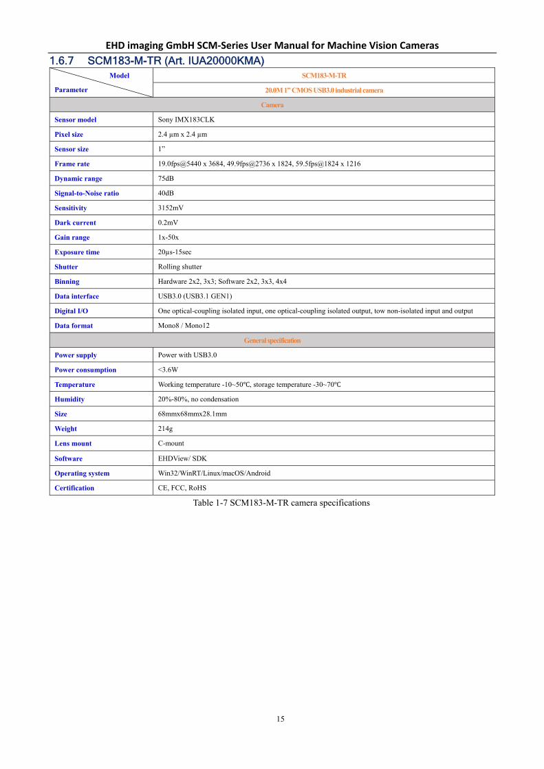
1.6.7 SCM183-M-TR (Art. IUA20000KMA) Model
Parameter
SCM183-M-TR
20.0M 1” CMOS USB3.0 industrial camera
Camera
Sensor model Sony IMX183CLK
Pixel size 2.4 µm x 2.4 µm
Sensor size 1”
Frame rate 19.0fps@5440 x 3684, 49.9fps@2736 x 1824, 59.5fps@1824 x 1216
Dynamic range 75dB
Signal-to-Noise ratio 40dB
Sensitivity 3152mV
Dark current 0.2mV
Gain range 1x-50x
Exposure time 20µs-15sec
Shutter Rolling shutter
Binning Hardware 2x2, 3x3; Software 2x2, 3x3, 4x4
Data interface USB3.0 (USB3.1 GEN1)
Digital I/O One optical-coupling isolated input, one optical-coupling isolated output, tow non-isolated input and output
Data format Mono8 / Mono12
General specification
Power supply Power with USB3.0
Power consumption <3.6W
Temperature Working temperature -10~50℃, storage temperature -30~70℃
Humidity 20%-80%, no condensation
Size 68mmx68mmx28.1mm
Weight 214g
Lens mount C-mount
Software EHDView/ SDK
Operating system Win32/WinRT/Linux/macOS/Android
Certification CE, FCC, RoHS
Table 1-7 SCM183-M-TR camera specifications

EHD imaging GmbH SCM‐Series User Manual for Machine Vision Cameras
16
Figure 1-7 SCM183‐M‐TR spectral response curve

EHD imaging GmbH SCM‐Series User Manual for Machine Vision Cameras
17
1.6.8 SCM183-C-TR (Art. IUA20000KPA) Model
Parameter
SCM183-C-TR
20.0M pixels 1” CMOS USB3.0industrial camera
Camera
Sensor model Sony IMX183CQK
Pixel size 2.4 µm x 2.4 µm
Sensor size 1”
Frame rate 19.0fps@5440 x 3684,49.9fps@2736 x 1824,59.5fps@1824 x 1216
Dynamic range 71dB
Signal-to-Noise ratio 40dB
Sensitivity 1874mV
Dark current 0.2mV
Gain range 1x-50x
Exposure time 20µs-15sec
Shutter Rolling shutter
Binning Hardware 2x2, 3x3; Software 2x2, 3x3, 4x4
Data interface USB3.0 (USB3.1 GEN1)
Digital I/O One optical-coupling isolated input, one optical-coupling isolated output, tow non-isolated input and output
Data format RAW8/RAW12/RGB8/RGB24/RGB32/RGB48
General specification
Power supply Power with USB3.0
Power consumption <3.6W
Temperature Working temperature -10~50℃, storage temperature-30~70℃
Humidity 20%-80%, no condensation
Size 68mmx68mmx28.1mm
Weight 214g
Lens mount C-mount
Software EHDView/ SDK
Operating system Win32/WinRT/Linux/macOS/Android
Certification CE, FCC, RoHS
Table 1-8 SCM183-C-TR Camera Parameters Index

EHD imaging GmbH SCM‐Series User Manual for Machine Vision Cameras
18
Figure 1-8 SCM183‐C‐TR spectral response curve

EHD imaging GmbH SCM‐Series User Manual for Machine Vision Cameras
19
1.7 IUB series technical specifications
1.7.1 SCM2020-M-TR (Art. IUB4200KMA) Model
Parameter
SCM2020-M-TR
4.2M pixels 1.2” CMOS USB3.0 industrial camera
Camera
Sensor model GSENSE2020s
Pixel size 6.5 µm x 6.5 µm
Sensor size 1.2”
Frame rate 45fps@2048 x 2046, 45fps@1024 x 1022
Dynamic range 66.6dB (LG), 59.5dB (HG), 87.5dB (HDR)
Signal-to-Noise ratio 46dB (LG), 32dB (HG)
Sensitivity 8.11x10⁷e-/((W/m2)·s)
Dark current 7e-/s/pix
Gain range 1x-22x
Exposure time TBD
Shutter Rolling shutter
Binning Software 2x2, 3x3, 4x4
Data interface USB3.0 (USB3.1 GEN1)
Digital I/O One optical-coupling isolated input, one optical-coupling isolated output, tow non-isolated input and output
Data format Mono8 / Mono12
General specification
Power supply Power with USB3.0/ 12V Power adapter
Power consumption <3.7W
Temperature Working temperature -10~50℃, storage temperature-30~70℃
Humidity 20%-80%, no condensation
Size 118mmx68mmx23.2mm
Weight 633g
Lens mount C-mount
Software EHDView/ SDK
Operating system Win32/WinRT/Linux/macOS/Android
Certification CE, FCC, RoHS
Table 1-9 SCM2020‐M‐TR camera specifications

EHD imaging GmbH SCM‐Series User Manual for Machine Vision Cameras
20
Figure 1-9 SCM2020‐M‐TR spectral response curve

EHD imaging GmbH SCM‐Series User Manual for Machine Vision Cameras
21
1.7.2 SCM2020-UV-TR (Art. IUB4200KMB) Model
Parameter
SCM2020-UV-TR
4.2M pixels 1.2” CMOS USB3.0 industrial camera
Camera
Sensor model GSENSE2020BSI
Pixel size 6.5 µm x 6.5 µm
Sensor size 1.2”
Frame rate 43.6fps@2048 x 2046, 43.6fps@1024 x 1022
Dynamic range 67.5dB (LG), 61dB (HG), 90.7dB (HDR)
Signal-to-Noise ratio 47dB (LG), 32dB (HG)
Sensitivity 1.1x10⁸ e-/((W/m2)·s)
Dark current 80e-/s/pix
Gain range 1x-50x
Exposure time TBD
Shutter Rolling shutter
Binning Software 2x2, 3x3, 4x4
Data interface USB3.0 (USB3.1 GEN1)
Digital I/O One optical-coupling isolated input, one optical-coupling isolated output, tow non-isolated input and output
Data format Mono8 / Mono12
General specification
Power supply Power with USB3.0/ 12V Power adapter
Power consumption <3.7W
Temperature Working temperature -10~50℃, storage temperature30~70℃
Humidity 20%-80%, no condensation
Size 118mmx68mmx23.2mm
Weight 633g
Lens mount C-mount
Software EHDView/ SDK
Operating system Win32/WinRT/Linux/macOS/Android
Certification CE, FCC, RoHS
Table 1-10 SCM2020-UV-TR camera specifications

EHD imaging GmbH SCM‐Series User Manual for Machine Vision Cameras
22
Figure 1-10 SCM2020‐UV‐TR spectral response curve

EHD imaging GmbH SCM‐Series User Manual for Machine Vision Cameras
23
1.7.3 SCM0806-M-TR (Art. IUB43000KMA) Model
Parameter
SCM0806-M-TR
43.0M pixels 1.7” (APS-C) CMOS USB3.0 industrial camera
Camera
Sensor model GMAX0806
Pixel size 2.8 µm x 2.8 µm
Sensor size 1.7’’ (APS-C)
Frame rate 8.5fps@7904x5432, 8.5fps@3952x2716
Dynamic range 66dB (2G), 63dB (6G)
Signal-to-Noise ratio 38.5dB (2G), 34dB (6G)
Sensitivity 1.19x10⁷ e-/((W/m2)·s)
Dark current 1e-/s/pix
Gain range 1x-6x
Exposure time TBD
Shutter Global shutter
Binning Hardware 2x2; Software 2x2, 3x3, 4x4
Data interface USB3.0 (USB3.1 GEN1)
Digital I/O One optical-coupling isolated input, one optical-coupling isolated output, tow non-isolated input and output
Data format Mono8 / Mono12
General specification
Power supply Power with USB3.0/ 12V Power adapter
Power consumption <5.0W
Temperature Working temperature -10~50℃, storage temperature-30~70℃
Humidity 20%-80%, no condensation
Size 118mmx68mmx23.2mm
Weight 633g
Lens mount M42 Interface
Software EHDView/ SDK
Operating system Win32/WinRT/Linux/macOS/Android
Certification CE, FCC, RoHS
Table 1-11 SCM0806-M-TR camera specifications

EHD imaging GmbH SCM‐Series User Manual for Machine Vision Cameras
24
Figure 1-11 SCM0806‐M‐TR spectral response curve

EHD imaging GmbH SCM‐Series User Manual for Machine Vision Cameras
25
1.8 IUC series technical specifications
1.8.1 SCM571-C-TR (Art. IUC26000KPA) Model
Parameter
SCM571-C-TR
26.0M pixels 1.8” (APS-C) CMOS USB3.0 industrial camera
Camera
Sensor model Sony IMX571BQR-C
Pixel size 3.76 µm x 3.76 µm
Sensor size 1.8’’ (APS-C)
Frame rate TBD
Dynamic range TBD
Signal-to-Noise ratio TBD
Sensitivity 484.5mv
Dark current 0.07mv
Gain range 1x-50x
Exposure time TBD
Shutter Rolling shutter
Binning TBD
Data interface USB3.0 (USB3.1 GEN1)
Digital I/O One optical-coupling isolated input, one optical-coupling isolated output, tow non-isolated input and output
Data format RAW8/RAW12/RAW14/RAW16/RGB8/RGB24/RGB32/RGB48
General specification
Power supply 12V Power adapter
Power consumption TBD
Temperature Working temperayure-10~50℃, storage temperature-30~70℃
Humidity 20%-80%, no condensation
Size 88mmx88mmx21.2mm
Weight TBD
Lens mount M42 Interface
Software EHDView/ SDK
Operating system Win32/WinRT/Linux/macOS/Android
Certification CE, FCC, RoHS
Table 1-12 SCM571-C-TR camera specifications

EHD imaging GmbH SCM‐Series User Manual for Machine Vision Cameras
26
Figure 1-12 SCM571‐C‐TR spectral response curve

EHD imaging GmbH SCM‐Series User Manual for Machine Vision Cameras
27
1.8.2 SCM342-M-TR (Art. IUC31000KMA) Model
Parameter
SCM342-M-TR
31.0M pixels 1.8” (APS-C) CMOS USB3.0 industrial camera
Camera
Sensor model Sony IMX342LLA
Pixel size 3.45 µm x 3.45 µm
Sensor size 1.8’’ (APS-C)
Frame rate 12.0fps@6464 x 4852, 45.9fps@3216 x 2426
Dynamic range 75dB
Signal-to-Noise ratio 40dB
Sensitivity 1830mV
Dark current 0.15mV
Gain range 1x-50x
Exposure time 31µs-15sec
Shutter Global shutter
Binning Hardware 2x2; Software 2x2, 3x3, 4x4
Data interface USB3.0 (USB3.1 GEN1)
Digital I/O One optical-coupling isolated input, one optical-coupling isolated output, tow non-isolated input and output
Data format Mono8 / Mono12
General specification
Power supply 12V Power adapter
Power consumption <7.7w
Temperature Working temperayure-10~50℃, storage temperature-30~70℃
Humidity 20%-80%, no condensation
Size 88mmx88mmx21.2mm
Weight 545g
Lens mount M42 Interface
Software EHDView/ SDK
Operating system Win32/WinRT/Linux/macOS/Android
Certification CE, FCC, RoHS
Table 1-13 SCM342-M-TR camera specifications

EHD imaging GmbH SCM‐Series User Manual for Machine Vision Cameras
28
Figure 1-13 SCM342‐M‐TR spectral response curve
EHD imaging GmbH SCM‐Series User Manual for Machine Vision Cameras
29
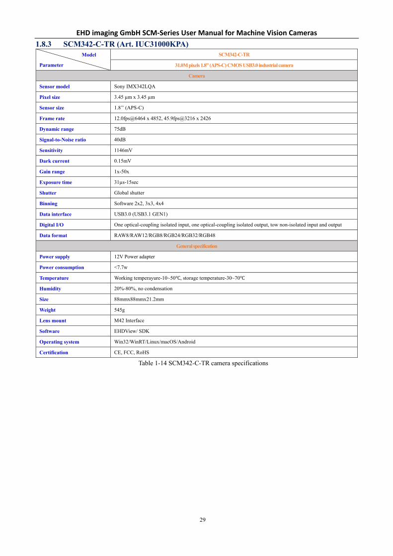
1.8.3 SCM342-C-TR (Art. IUC31000KPA) Model
Parameter
SCM342-C-TR
31.0M pixels 1.8” (APS-C) CMOS USB3.0 industrial camera
Camera
Sensor model Sony IMX342LQA
Pixel size 3.45 µm x 3.45 µm
Sensor size 1.8’’ (APS-C)
Frame rate 12.0fps@6464 x 4852, 45.9fps@3216 x 2426
Dynamic range 75dB
Signal-to-Noise ratio 40dB
Sensitivity 1146mV
Dark current 0.15mV
Gain range 1x-50x
Exposure time 31µs-15sec
Shutter Global shutter
Binning Software 2x2, 3x3, 4x4
Data interface USB3.0 (USB3.1 GEN1)
Digital I/O One optical-coupling isolated input, one optical-coupling isolated output, tow non-isolated input and output
Data format RAW8/RAW12/RGB8/RGB24/RGB32/RGB48
General specification
Power supply 12V Power adapter
Power consumption <7.7w
Temperature Working temperayure-10~50℃, storage temperature-30~70℃
Humidity 20%-80%, no condensation
Size 88mmx88mmx21.2mm
Weight 545g
Lens mount M42 Interface
Software EHDView/ SDK
Operating system Win32/WinRT/Linux/macOS/Android
Certification CE, FCC, RoHS
Table 1-14 SCM342-C-TR camera specifications

EHD imaging GmbH SCM‐Series User Manual for Machine Vision Cameras
30
Figure 1-14 SCM342‐C‐TR spectral response curve

EHD imaging GmbH SCM‐Series User Manual for Machine Vision Cameras
31
1.8.4 SCM455-M-TR (Art. IUC60000KMA) Model
Parameter
SCM455-M-TR
60.0M pixels 2.7” (Full Frame) CMOS USB3.0 industrial camera
Camera
Sensor model Sony IMX455ALK
Pixel size 3.76 µm x 3.76 µm
Sensor size 2.7’’ (Full Frame)
Frame rate TBD
Dynamic range TBD
Signal-to-Noise ratio TBD
Sensitivity TBD
Dark current TBD
Gain range TBD
Exposure time TBD
Shutter Rolling shutter
Binning TBD
Data interface USB3.0 (USB3.1 GEN1)
Digital I/O One optical-coupling isolated input, one optical-coupling isolated output, tow non-isolated input and output
Data format Mono8/Mono12/Mono14/Mono16
General specification
Power supply 12V Power adapter
Power consumption TBD
Temperature Working temperayure-10~50℃, storage temperature-30~70℃
Humidity 20%-80%, no condensation
Size 88mmx88mmx21.2mm
Weight TBD
Lens mount M52 Interface
Software EHDView/ SDK
Operating system Win32/WinRT/Linux/macOS/Android
Certification CE, FCC, RoHS
Table 1-15 SCM455-M-TR camera specifications

EHD imaging GmbH SCM‐Series User Manual for Machine Vision Cameras
32
Figure 1-15 SCM455‐M‐TR spectral response curve

EHD imaging GmbH SCM‐Series User Manual for Machine Vision Cameras
33
1.8.5 SCM455-C-TR (Art. IUC60000KPA) Model
Parameter
SCM455-C-TR
60.0M pixels 2.7” (Full Frame) CMOS USB3.0 industrial camera
Camera
Sensor model Sony IMX455AQK
Pixel size 3.76 µm x 3.76 µm
Sensor size 2.7’’ (Full Frame)
Frame rate TBD
Dynamic range TBD
Signal-to-Noise ratio TBD
Sensitivity TBD
Dark current TBD
Gain range TBD
Exposure time TBD
Shutter Rolling shutter
Binning TBD
Data interface USB3.0 (USB3.1 GEN1)
Digital I/O One optical-coupling isolated input, one optical-coupling isolated output, tow non-isolated input and output
Data format RAW8/RAW12/RAW14/RAW16/RGB8/RGB24/RGB32/RGB48
General specification
Power supply 12V Power adapter
Power consumption TBD
Temperature Working temperayure-10~50℃, storage temperature-30~70℃
Humidity 20%-80%, no condensation
Size 88mmx88mmx21.2mm
Weight TBD
Lens mount M52 Interface
Software EHDView/ SDK
Operating system Win32/WinRT/Linux/macOS/Android
Certification CE, FCC, RoHS
Table 1-16 SCM455-C-TR camera specifications

EHD imaging GmbH SCM‐Series User Manual for Machine Vision Cameras
34
Figure 1-16 SCM455‐C‐TR spectral response curve

EHD imaging GmbH SCM‐Series User Manual for Machine Vision Cameras
35
2 Camera Dimension and Interface
2.1 IUA series camera dimensions and outputs
2.1.1 IUA series camera mechanical housing dimensions
Figure 2-1 IUA series camera
Figure 2-2 Dimensions of IUA camera housing (mm)
Figure 2-3 Dimensions of IUA circuit board (mm)

EHD imaging GmbH SCM‐Series User Manual for Machine Vision Cameras
36
2.1.2 IUA series camera interface The back of the industrial camera is shown in Figure 2-4. It has standard USB3.0 output, 7 Pin I/O port (aviation head)
and on/off indicator. It has two M2 screw holes on both sides of USB 3.0 port to fix the cable. The holes reduce cable
loosening caused by field vibration.
Figure 2-4 Schematic diagram of IUA camera back panel
2.1.3 IUA series camera power supply and I/O connector The pin signal definition for the IUA series camera 7 Pin I/O connector is shown in Table 2-1.
Color Pin Signal Signal description
White 1 GND Direct-coupled signal ground
Red 2 5V 5VDC power input or output
Blue 3 OPTO_GND Opto-isolated signal ground
Yellow 4 DIR_GPIO1
Direct-coupled General Purpose I/O (Software configurable input/output)
(line2)
Black 5 DIR_GPIO2
Direct-coupled General Purpose I/O (Software configurable input/output)
(line3)
Green 6 OPTO_IN Opto-isolated input signal (line0)
Pink 7 OPTO_OUT Opto-isolated output signal (line1)
Table 2-1 IUA series pin signal definition
2.1.4 IUA series camera packing information For normal use of industrial cameras, please prepare the required accessories as shown in Table 2-2 before installation.
Order number Accessories name Quantity Instruction
1 Camera 1 Camera referred in this manual
2 I/O cable 1 7 Pin cable or extended cable
3 USB3.0 cable 1 Suitable length of Micro USB3.0 cable
4 Lens (optional) 1 C-mount lens
Table 2-2 Recommended accessories

EHD imaging GmbH SCM‐Series User Manual for Machine Vision Cameras
37
2.2 IUB series camera dimensions and outputs
2.2.1 IUB series camera mechanical housing dimensions
Figure 2-5 IUB series camera
Figure 2-6 Dimensions of IUB camera housing (mm)

EHD imaging GmbH SCM‐Series User Manual for Machine Vision Cameras
38
Figure 2-7 Dimensions of IUB circuit board (mm)
2.2.2 IUB series camera interface The back of the industrial camera is shown in Figure 2-8. It has standard USB3.0 output, 7 Pin I/O port (aviation head)
and on/off indicator. It has two M2 screw holes on both sides of USB 3.0 port to fix the cable. The holes reduce cable
loosening caused by field vibration.
Figure 2-8 Schematic diagram of IUB camera back panel
2.2.3 IUB series camera power supply and I/O connector The pin signal definition for the IUB, IUC series camera 7 Pin I/O connector is shown in Table 2-3.
Color Pin Signal Signal description
White 1 GND Direct-coupled signal ground
Red 2 12V 12VDC power input or output
Blue 3 OPTO_GND Opto-isolated signal ground
Yellow 4 DIR_GPIO1 Direct-coupled General Purpose I/O (Software configurable input/output) (line2)
Black 5 DIR_GPIO2 Direct-coupled General Purpose I/O (Software configurable input/output) (line3)
Green 6 OPTO_IN Opto-isolated input signal (line0)
Pink 7 OPTO_OUT Opto-isolated output signal (line1)
Table 2-3 IUB series pin signal definitions

EHD imaging GmbH SCM‐Series User Manual for Machine Vision Cameras
39
2.2.4 IUB series camera packing information For normal use of industrial cameras, please prepare the required accessories as shown in Table 2-4 before installation.
Order number Accessories name Quantity Instruction
1 Camera 1 Camera referred in this manual
2 I/O cable 1 7 Pin cable or extended cable
3 USB3.0 cable 1 Suitable length of Micro USB3.0 cable
4 Power (IUB) 1 IUB series of power adapters
5 Lens (optional) 1 C-mount lens
Table 2-4 Recommended accessories

EHD imaging GmbH SCM‐Series User Manual for Machine Vision Cameras
40
2.3 IUC series camera dimensions and outputs
2.3.1 IUC series camera mechanical housing dimensions
Figure 2-9 IUC series camera
Figure 2-10 Dimensions of IUC camera housing (mm)
EHD imaging GmbH SCM‐Series User Manual for Machine Vision Cameras
41
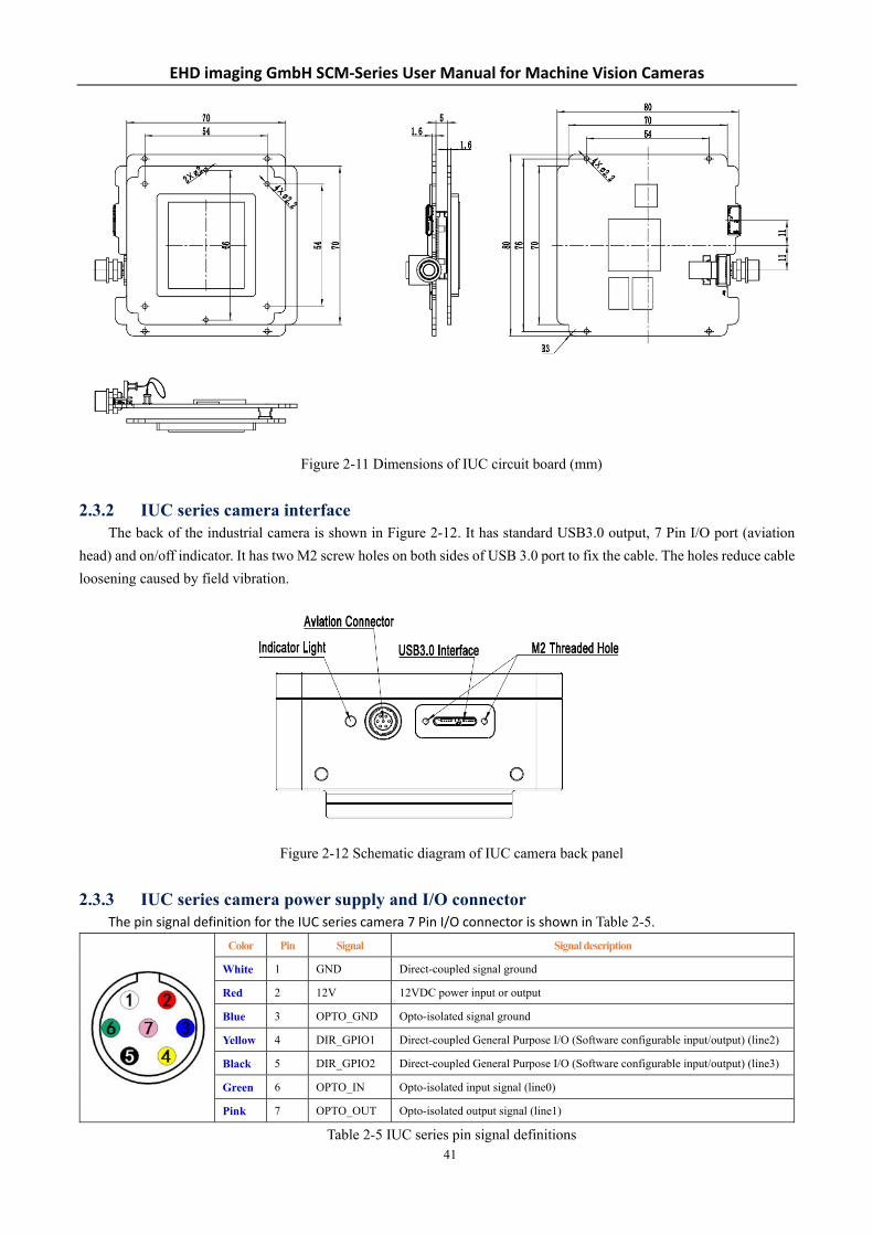
Figure 2-11 Dimensions of IUC circuit board (mm)
2.3.2 IUC series camera interface The back of the industrial camera is shown in Figure 2-12. It has standard USB3.0 output, 7 Pin I/O port (aviation
head) and on/off indicator. It has two M2 screw holes on both sides of USB 3.0 port to fix the cable. The holes reduce cable
loosening caused by field vibration.
Figure 2-12 Schematic diagram of IUC camera back panel
2.3.3 IUC series camera power supply and I/O connector The pin signal definition for the IUC series camera 7 Pin I/O connector is shown in Table 2-5.
Color Pin Signal Signal description
White 1 GND Direct-coupled signal ground
Red 2 12V 12VDC power input or output
Blue 3 OPTO_GND Opto-isolated signal ground
Yellow 4 DIR_GPIO1 Direct-coupled General Purpose I/O (Software configurable input/output) (line2)
Black 5 DIR_GPIO2 Direct-coupled General Purpose I/O (Software configurable input/output) (line3)
Green 6 OPTO_IN Opto-isolated input signal (line0)
Pink 7 OPTO_OUT Opto-isolated output signal (line1)
Table 2-5 IUC series pin signal definitions

EHD imaging GmbH SCM‐Series User Manual for Machine Vision Cameras
42
2.3.4 IUC series camera packing information For normal use of industrial cameras, please prepare the required accessories as shown in Table 2-6 before installation.
Order number Accessories name Quantity Instruction
1 Camera 1 Camera referred in this manual
2 I/O cable 1 7 Pin cable or extended cable
3 USB3.0 cable 1 Suitable length of Micro USB3.0 cable
4 Power (IUC) 1 Power adapter for IUC series
5 Lens (optional) 1 C-mount lens
Table 2-6 Recommended accessories

EHD imaging GmbH SCM‐Series User Manual for Machine Vision Cameras
43
3 Description of Software Development
3.1 SDK introduction
3.1.1 SDK support platform Win32:
x86: XP SP3 and above versions; CPU needs to support the SSE2 instruction set at least
x64: Win7 and above versions
arm: Win10 and above versions
arm64: Win10 and above versions
WinRT: x86, x64, arm, arm64;Windows 10 or above versions
macOS: x86 and x64 bundle;macOS 10.10 or above versions
Linux: core 2.6.27 and above versions
x86: CPU needs to support at least SSE3 instruction sets; GLIBC 2.8 and above
x64: GLIBC 2.14 and above versions
armel: GLIBC 2.17 and above versions. Compiled by toolchain arm-linux-gnueabi (version 4.9.2)
armhf: GLIBC 2.17 and above versions; Compiled by toolchain arm-linux-gnueabihf (version 4.9.2)
arm64: GLIBC 2.17 and above versions; Compiled by toolchain aarch64-linux-gnu (version 4.9.2)
Android: arm, arm64, x86, x64; Compiled by android-ndk-r18b.
3.1.2 SDK content brief introduction EHD-SCM series cameras support a variety of API, including: Native C/C++, NET / C#VB.NET, DirectShow,
Twain, LabView and so on. Compared with other API, as the low-level API, native C/C++ API is characterized by
using pure C/C++ development, independent of other runtime libraries, having simple interface and flexible control.
This SDK package contains all the resources and information you need to use, as follows:
inc:
toupcam.h, C/C++ Header file.
win: Microsoft Windows Platform file
dotnet:
toupcam.cs, Support for C#. toupcam.cs, use P/Invoke to call to toupcam.dll. Please copy
toupcam.cs to your C # project.
toupcam.vb, Support for VB.NET. toupcam.vb uses P/Invoke to call to toupcam.dll.
Please copy toupcam.vb to your VB.NET project
x86:
toupcam.lib, x86 lib file.
toupcam.dll, x86 dynamic library files.
democpp.exe, x86 C++ demo execute the procedure.
x64:
toupcam.lib, x64 lib file.
toupcam.dll, x64 dynamic library files.
democpp.exe, x64 C++ demo execute the procedure.
arm:
toupcam.lib, arm lib file.
toupcam.dll, arm dynamic library files.
arm64:
toupcam.lib, arm64 lib file.
toupcam.dll, arm64 dynamic library files.

EHD imaging GmbH SCM‐Series User Manual for Machine Vision Cameras
44
winrt:
They can be applied for Dynamic library files of WinRT/ UWP (Universal Windows Platform)/ Windows Store
App. They are compatible with Windows Runtime and can be referenced by the Universal Windows Platform
app. If you use C # to develop UWP, you can use the toupcam.cs to wrap class.
Please pay attention to the DeviceCapability of uwp. Refer to How to add USB device capabilities
to the app manifest. (Microsoft seems to limit the Device entry under DeviceCapability to no more than
100) demouwp.zip is a simple example of uwp. Please modify vid and pid. under DeviceCapability in the
file Package.appxmanifest before compiling the run example.
drivers: (Cameras produced after 2017.1.1 support WinUSB. You no longer need to install drivers
on Windows8 and above)
The x86 folder contains the kernel state driver file for x86, including toupcam.cat, toupcam.inf and
toupcam.sys.
The x64 folder contains the kernel state driver file for x64, including toupcam.cat, toupcam.inf and
toupcam.sys
samples:
1.democpp, take C++ for example. This example shows an enumeration device, an open device, a preview
video, a snap image, a set resolution, a trigger and a wide variety of picture formats (bmp, jpg, png etc.) save
the image to the file, wmv format video, trigger mode, I/O control, etc. This example uses the Pull Mode
mechanism. In order to keep the code clean, the WTL library used by the example can be downloaded from
this link http: //sourceforge.net/projects/wtl/
2.demopush, take C++ for example, using the Push Mode mechanism, StartPushModeV3
3.demomfc, A simple C++ example. it uses MFC as the GUI library, supports opening devices, previews video,
captures images, sets resolution and saves images to files in a variety of image formats (.bmp, .jpg, .png, etc.).
This example uses the Pull Mode mechanism.
4.demowinformcs1, take C# winform for example. It supports to open the device, preview video, capture
images, save pictures to files and set white balance. This example uses the PullMode mechanism, called
StartPullModeWithWndMsg.
5.demowinformcs2, take C# winform for example. It supports to open the device, preview video, capture
images, save pictures to files, set white balance. This example uses the Pull Mode mechanism called
StartPullModeWithCallback
6.demowinformcs3, take C# winform for example. It supports to open the device, preview video, capture
images, save pictures to files, set white balance. This example uses the Push Mode mechanism called
StartPushMode
7.demowinformvb, take VB.NET winform for example. It supports to open the device, preview video, capture
images, save pictures to files and set white balance. This example uses the Pull Mode mechanism.
linux: Linux platform file
Udev: 99-toupcam.rules, udev rule file
Please refer to: http: //reactivated.net/writing_udev_rules.html
c#: toupcam.cs, Support. Net Core C#. toupcam.cs calls to libtoupcam.so. using P/Invoke Please
copy toupcam.cs to your C # project.
x86: libtoupcam.so, X86 version of so file.
x64: libtoupcam.so, x64 version of so file.
armel: libtoupcam.so, armel version so file, toolchain is arm-linux-gnueabi
armhf: libtoupcam.so, armhf version so file, toolchain isarm-linux-gnueabihf
arm64: libtoupcam.so, Arm64 version so file, toolchain is aarch64-linux-gnu
android: Android platform. libtoupcam.so. for the four architectures of arm, arm64, x86, x64

EHD imaging GmbH SCM‐Series User Manual for Machine Vision Cameras
45
mac: macOS platform file
python: toupcam.py and example code.
java: toupcam.java and example code(Console and Swing)
doc: SDK uses documentation, simplified Chinese, English.
sample:
demosimplest, the simplest example is about 60 lines of code.
demoraw, RAW data and static capture, about 120 lines of code.
extras:
directshow: DirectShow SDK and demo programs.
twain: TWAIN SDK
labview: Labview SDK and demo programs.
MATLAB: MATLAB demo programs.
3.2 Client democpp description
As shown in Figure 3-1, “1” is the control menu area and "2" is the video display area.
Figure 3-1 democpp interface
The main features of the control menu are:
Device: camera names installed are listed under this menu. Clicking the camera name to open the camera;
Resolution: switch the resolution and capture the image;
Action: Pause, ROI setting, test image, read firmware version number, hardware version number, production
date, etc.
Trigger: Defining the trigger mode, the I/O port setting and the like;
Config: Set exposure, gain, white balance, frame rate, etc.
3.3 EHDView UI description
EHDView software fully controls all camera features and streams high-speed videos by USB port using Ultra
FineTM color engine. Ultra FineTM color engine contains excellent procedure of processing RAW data and thus realizes
the conversion of sensor detected data to image. Furthermore, ToupView also provides many advanced video and
image processing features, such as image gray level correction, 2D measurement, stitching, depth of field extension,

EHD imaging GmbH SCM‐Series User Manual for Machine Vision Cameras
46
video watermarking, color synthesis, image segmentation and counting and so on. EHDView’s multilingual
environment can support any language and currently includes, but is not limited to, English, simplified Chinese,
traditional Chinese, German, Japanese, Russian, French, Italian, Polish, Turkish, etc. The UI of EHDView is shown
in Figure 3-2.
Figure 3-2 EHDView UI
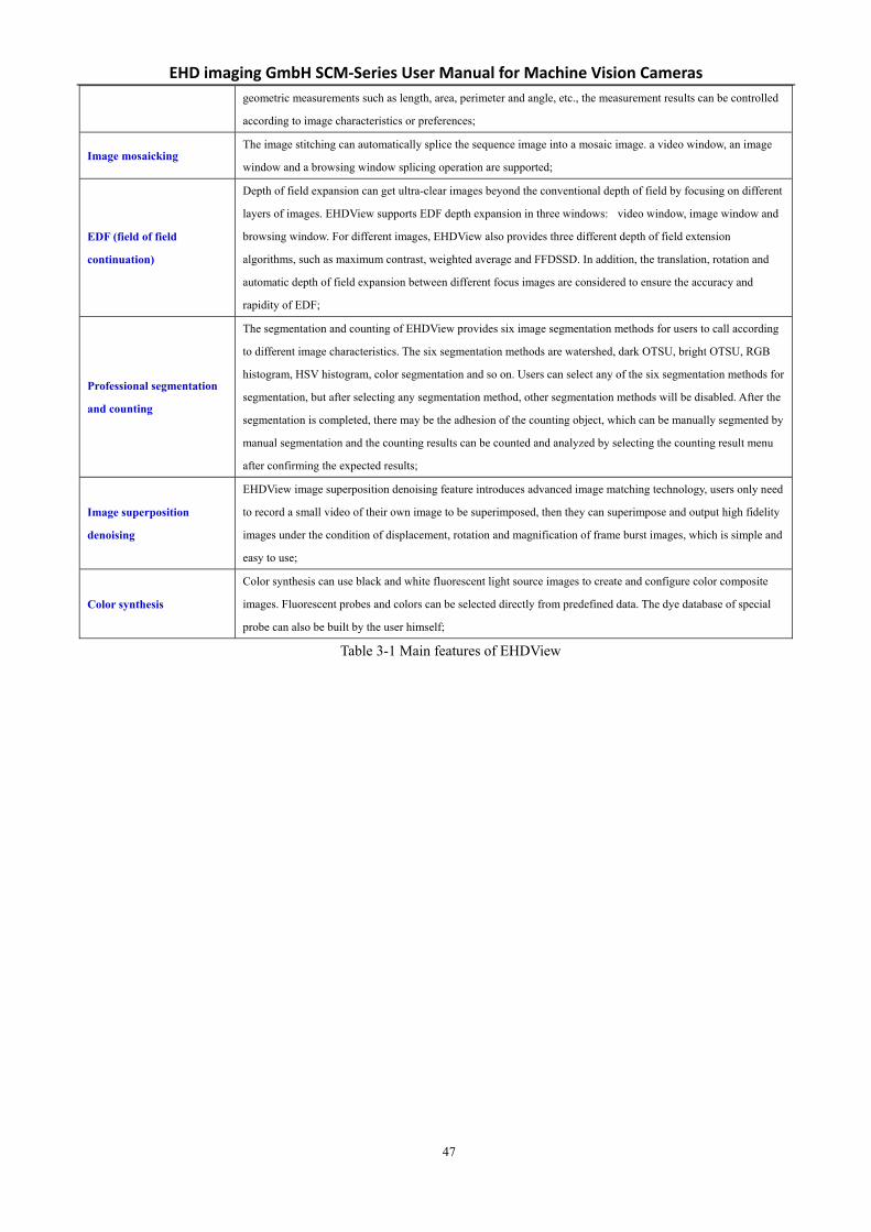
The main features of EHDView are shown in Table 3-1.
Exposure and gain Automatic exposure, manual exposure, gain up to 5x;
White balance Automatic white balance; can be adjusted by manually setting the color temperature and color;
Color adjustment Color, saturation, brightness, contrast, gamma value adjustment feature;
Frame rate control According to the performance of different computers and USB, the compatibility of the camera can be realized by
adjusting the frame rate;
Light source frequency
control Natural light / DC, AC50HZ, AC60HZ selection button eliminates video flicker;
Acoustic image The direction of the adjustable sample can be adjusted by "horizontal" or "vertical" and is consistent with the
direction of the visual system;
Sampling and
neighborhood averaging
and other features
Neighborhood average can improve the signal-to-noise ratio of video stream and sampling extraction mode can
ensure the sharpness of video stream. Support video stream histogram expansion, image negative and positive film
switching, gray calibration, clarity factor calculation to facilitate video focusing;
Parameter saving Load, save, overwrite, load, export custom camera panel control;
Video feature
video broadcasting, timing capture, video recording, video watermarking, watermark movement alignment,
watermark rotation alignment, video grid overlay, video measurement, video scaling, grayscale scaling calibration,
video high dynamic (HDR), video depth of field expansion, video image stitching, video scale, the date and the
like are superimposed;
Image processing and
enhancement
Image contrast control and adjustment, image de-noising, various image filter algorithms, image mathematical
morphology algorithm, image rotation, image scaling and image printing;
2D measurement Convenient and practical video and image size calibration, a variety of video and image two-dimensional
EHD imaging GmbH SCM‐Series User Manual for Machine Vision Cameras
47
geometric measurements such as length, area, perimeter and angle, etc., the measurement results can be controlled
according to image characteristics or preferences;
Image mosaicking The image stitching can automatically splice the sequence image into a mosaic image. a video window, an image
window and a browsing window splicing operation are supported;
EDF (field of field
continuation)
Depth of field expansion can get ultra-clear images beyond the conventional depth of field by focusing on different
layers of images. EHDView supports EDF depth expansion in three windows: video window, image window and
browsing window. For different images, EHDView also provides three different depth of field extension
algorithms, such as maximum contrast, weighted average and FFDSSD. In addition, the translation, rotation and
automatic depth of field expansion between different focus images are considered to ensure the accuracy and
rapidity of EDF;
Professional segmentation
and counting
The segmentation and counting of EHDView provides six image segmentation methods for users to call according
to different image characteristics. The six segmentation methods are watershed, dark OTSU, bright OTSU, RGB
histogram, HSV histogram, color segmentation and so on. Users can select any of the six segmentation methods for
segmentation, but after selecting any segmentation method, other segmentation methods will be disabled. After the
segmentation is completed, there may be the adhesion of the counting object, which can be manually segmented by
manual segmentation and the counting results can be counted and analyzed by selecting the counting result menu
after confirming the expected results;
Image superposition
denoising
EHDView image superposition denoising feature introduces advanced image matching technology, users only need
to record a small video of their own image to be superimposed, then they can superimpose and output high fidelity
images under the condition of displacement, rotation and magnification of frame burst images, which is simple and
easy to use;
Color synthesis
Color synthesis can use black and white fluorescent light source images to create and configure color composite
images. Fluorescent probes and colors can be selected directly from predefined data. The dye database of special
probe can also be built by the user himself;
Table 3-1 Main features of EHDView

EHD imaging GmbH SCM‐Series User Manual for Machine Vision Cameras
48
4 Camera Installation and Operation
4.1 Installation steps
1.Fix the camera onto the installation position and attach appropriate C-mount lens to the camera.
2.Verify that the camera is properly connected to the industrial computer or PC using the Micro USB3.0 cable that
comes with the camera. Tighten the cable by fastening screw at the camera side.
4.2 Driver check
The Operation Systems under Windows 7(Including WIN7) require a normal installation of the drive before the camera is
used and if the drive installation fails, the camera will not be found by the client software.
After the installation is complete, in the Device Manager, you can see the new device type, such as I3CMS05000KMB and
then right-click the mouse button to see if the device drive is properly installed or not, as shown in Figure 4-1.
Figure 4-1 EHD driver attribute Figure 4-2 Win USB driver attribute
The operating systems above Windows 8(Including Windows 8) will install the driver automatically after the
camera is connected and the driver name is USB3.0 Camera, as shown in Figure 4-2.
4.3 Setup and operation
As shown in Figure 4-3, open democpp.exe and click "Device" in the top control menu, where all connected
cameras are displayed and click on the corresponding camera name to run the camera.

EHD imaging GmbH SCM‐Series User Manual for Machine Vision Cameras
49
Figure 4-3 democpp UI

EHD imaging GmbH SCM‐Series User Manual for Machine Vision Cameras
50
5 Main Features of democpp
5.1 Description of main features
As shown in Figure 5-1, in the democpp, click the "Resolution-> Preview" in the top control menu to select the
resolution of the camera; "Resolution->Snap" captures image at current resolution; "Resolution->Snap Multiple" captures
multiple images at the specified resolution.
Figure 5-1 Acquisition and resolution
The following is the API code for the image capture operation:
//still image snap
Toupcam_Snap(HToupCam h, unsigned nResolutionIndex);
//multiple still image snap
Toupcam_SnapN (HToupCam h, unsigned nResolutionIndex, unsigned nNumber);
//The following is the API code that sets the resolution.:
Toupcam_put_Size(HToupCam h, int nWidth, int nHeight);
Toupcam_put_eSize(HToupCam h, unsigned nResolutionIndex);
5.2 Image format and frame rate
The camera supports a variety of image file formats and the setup of image region of interest. The smaller image ROI
will have higher frame rate.
5.2.1 Camera data format
The list of pixel formats supported by the IUX series cameras are shown in Table 5-1 (“Y” for supported; “-”
for not supported)

EHD imaging GmbH SCM‐Series User Manual for Machine Vision Cameras
51
Format RAW8 RAW10 RAW12 RAW14 RGB8 RGB24 RGB32 RGB48
SCM432-M-TR Y --- Y --- Y Y Y Y
SCM432-C-TR Y --- Y --- Y Y Y Y
SCM178-M-TR Y --- Y --- Y Y Y Y
SCM178-C-TR Y --- Y --- Y Y Y Y
SCM428-M-TR Y --- Y --- Y Y Y Y
SCM428-C-TR Y --- Y --- Y Y Y Y
SCM183-M-TR Y --- Y --- Y Y Y Y
SCM183-C-TR Y --- Y --- Y Y Y Y
SCM2020-M-TR Y --- Y --- Y Y Y Y
SCM2020-UV-TR Y --- Y --- Y Y Y Y
SCM0806-M-TR Y --- Y --- Y Y Y Y
SCM571-C-TR Y --- Y Y Y Y Y Y
SCM342-M-TR Y --- Y --- Y Y Y Y
SCM342-C-TR Y --- Y --- Y Y Y Y
SCM455-M-TR Y --- Y Y Y Y Y Y
SCM455-C-TR Y --- Y Y Y Y Y Y
Table 5-1 IUX series camera Image data format
5.2.2 Frame rate The maximum frame rate that the camera can achieve is determined by the following three factors:
Frame readout time, the smaller the image height, the shorter the time required to read out, the higher the frame
rate.
Exposure time, the shorter the exposure time, the higher the frame rate.
Bandwidth, the larger the bandwidth, the higher the frame rate that supports transmission.
As shown in Figure 5-2, in democpp, click "Config->Speed" in the top control menu and drag the slider bar in "Speed"
dialog to set the frame rate.
Figure 5-2 Frame rate setup
The following is the API code for the setup of the frame rate:
Toupcam_put_Speed(HToupCam h, unsigned short nSpeed);

EHD imaging GmbH SCM‐Series User Manual for Machine Vision Cameras
52
5.2.3 Area of interest setup When the user is only interested in some details of the image, the camera can output the image ROI according to the
requirement. Setup the image ROI can reduce the transmission data bandwidth and improve the camera frame rate to a
certain extent.
Figure 5-3 Area of interest setup
As shown in Figure 5-3, in democpp, click "Action->ROI" in the upper control menu and in "ROI" dialog, fill x Offset, y
Offset, x Width, y Width to adjust the ROI, where the values in x Offset and y Offset represent the starting point of the ROI
up left corner.
The following is the API code for the setup of the image ROI:
Toupcam_put_Roi(HToupCam h, unsigned xOffset, unsigned yOffset, unsigned xWidth, unsigned yHeight);
5.3 Global Shutter and Rolling Shutter
5.3.1 Global Shutter For cameras that support global shutter, exposure starts in each line simultaneously. After the exposure, data is read
out line by line, as shown in Figure 5-4.
Figure 5-4 global shutter exposure principle

EHD imaging GmbH SCM‐Series User Manual for Machine Vision Cameras
53
5.3.2 Rolling Shutter For cameras that support rolling shutter, after the first line exposure, the next line begins to exposure, repeat in this
way. Sensor receive exposure and data read the time length to be consistent, but the time of begin to receive exposure is
inconsistent, as shown in Figure 5-5.
Figure 5-5 Rolling shutter exposure principle
5.4 Image acquisition and transmission
There are two image acquisition modes, free run mode and trigger mode. Among them, the free run mode is continuous
acquisition mode and the trigger mode captures one or more frames of images according to the trigger signal. The trigger
sources include software trigger and external trigger.
As shown in Figure 5-6, in democpp, the free run mode and trigger mode are switched by clicking on "Trigger" menu and
choosing “Enter Trigger Mode” command. The "✔" checkmark indicates that the current mode is in trigger mode, otherwise
free run mode.
Figure 5-6 Image acquisition mode switching

EHD imaging GmbH SCM‐Series User Manual for Machine Vision Cameras
54
The following are the API codes for the switching of the free run mode to trigger mode:
// 0 = video mode, 1 = software or simulated trigger mode, 2 = external trigger mode
Toupcam_put_Option(m_hCam, TOUPCAM_OPTION_TRIGGER, val);
5.4.1 Free run mode Under free run mode, the user can control the camera to continuously output images. Starting the democpp software,
connecting the camera and clicking run, the camera will run under free run mode by default. The camera continuously
outputs the image according to the current setting.
5.4.2 Trigger mode After the camera enters the trigger mode, it enters the waiting trigger state automatically. After receiving a trigger
signal, the camera begins to expose and after the exposure is finished, the image data will be flashed out. Under trigger
mode, image acquisition methods have single frame trigger, multi frame trigger, counter trigger and PWM trigger mode.
5.4.3 Trigger signal source selection
Under the trigger mode, trigger signal source is either from software trigger, or from external trigger. The external
trigger signal is from either the pin isolated by opto-coupler or the non-isolated pin.
The following is the API code for the setup of the trigger source:
// Trigger Source: 0-> line0 , 1-> line2 , 2-> line3 , 3-> Counter , 4-> PWM , 5-> Software
Toupcam_IoControl(m_hCam, 0, TOUPCAM_IOCONTROLTYPE_SET_TRIGGERSOURCE, val, NULL);
Software trigger
The camera supports software trigger mode. When a software trigger is executed, the client software will send the
command through USB3.0 to activate the camera to acquire and transmit images.
As shown in Figure 5-7, in democpp, first click "Enter Trigger Mode" to enter trigger mode. Click "Set trigger Number"
to define the number of triggers and finally click "Trigger" and the software will receive the number of triggers. If you
click "Loop Trigger", you will enter a continuous trigger mode and clicking it again will exit the current trigger mode.
Figure 5-7 Software trigger setup

EHD imaging GmbH SCM‐Series User Manual for Machine Vision Cameras
55
Figure 5-8 Set the external trigger source
Figure 5-8 shows the configuration of external trigger. First select "Enter Trigger Mode" to enter trigger mode. Then
click "IO Config" and the I/O Control dialog will pop up as shown in Figure 5-9. The trigger source is selected in the
"Trigger Source" and then click "OK". At this time a high pulse will trigger the camera on the corresponding line.
Figure 5-9 I/O control dialog
5.4.4 Frame burst mode The camera provides a frame burst mode, that is, receiving one trigger signal and producing multiple burst images.
The trigger frame value can range from 1 to 1023. “Burst Count = 1” means a one-frame image output, as shown in Figure
5-10, “Burst Count = 3” means a three-frame image output.
Figure 5-10 Frame burst trigger timing
Here is the API code for the setup of the trigger frame value
Toupcam_IoControl(m_hCam, 0, TOUPCAM_IOCONTROLTYPE_SET_BURSTCOUNTER, val, NULL);
Trigger_in
Triggerdelay
Sensorexposure1
Sensorexposure2
Sensorexposure3

EHD imaging GmbH SCM‐Series User Manual for Machine Vision Cameras
56
5.4.5 Counter trigger mode Under this mode, trigger signal number is divided by user-defined counter value. For example, when you set the
counter to 3, the camera needs to receive three trigger signals before it can begin exposure, as shown in Figure 5-11.
Figure 5-11 Counter trigger mode
The specific operation in democpp are shown in Figure 5-12. First, under "Trigger Source", select the trigger source as
Counter, then click "Counter Source" to select the external trigger source that needs to be divided and configure the
frequency division coefficient in "Counter Value" in the range of 1-1023. "Counter Reset" can clear the current frequency
division counter to zero.
Figure 5-12 Counter trigger mode setup
The following is the API code for the setup of the counter trigger mode:
Toupcam_IoControl(m_hCam, 0, TOUPCAM_IOCONTROLTYPE_SET_TRIGGERSOURCE, 3, NULL);
//Counter Source: 0-> line0 , 1-> line2 , 2-> line3
Toupcam_IoControl(m_hCam, 0, TOUPCAM_IOCONTROLTYPE_SET_COUNTERSOURCE, val, NULL);
Toupcam_IoControl(m_hCam, 0, TOUPCAM_IOCONTROLTYPE_SET_COUNTERVALUE, val, NULL);
5.4.6 PWM trigger mode The camera provides Pulse Width Modulation (PWM) trigger mode, which controls exposure time by pulse width.
The main difference between this mode and the standard single frame trigger mode is the exposure method. The exposure
time per frame is determined by the trigger pulse width, as shown in Figure 5-13.
Trigger
exposure
Sensor exposure1
Sensor exposure2
Triggerdelay
Triggerdelay
Trigger_in1 Trigger_in2 Trigger_in3
Sensorexposure1
Sensorexposure2
Sensorexposure3
Debouncetime
Debouncetime
Debouncetime
t1
t1
t2
t2
t3
t3

EHD imaging GmbH SCM‐Series User Manual for Machine Vision Cameras
57
Figure 5-13 PWM mode timing
The following cameras with rolling shutter sensors do not support PWM trigger mode:
SCM178-M-TR, SCM178-C-TR; SCM183-M-TR, SCM183-C-TR,
SCM2020-M-TR, SCM2020-UV-TR;
SCM271-C-TR, SCM455-M-TR, SCM455-C-TR
As shown in Figure 5-14 in democpp, select the trigger source as PWM, under "Trigger Source" and click "PWM
Source" to select the external trigger source for input.
The following is the API code for the setup of the counter trigger mode:
Toupcam_IoControl(m_hCam, 0, TOUPCAM_IOCONTROLTYPE_SET_TRIGGERSOURCE, 4, NULL);
Toupcam_IoControl(m_hCam, 0, TOUPCAM_IOCONTROLTYPE_SET_PWMSOURCE, val, NULL);
Figure 5-14 PWM mode parameter control
5.5 Input signal
5.5.1 Signal debouncer Because the external trigger input signal of the camera may have burr, if it goes directly into the internal logic of the
camera, it will cause false trigger. The input trigger signal should be debounced. In addition, the effective pulse width of
the trigger signal inputted by the user should be greater than the debouncer time, otherwise the trigger signal will be ignored.
The timing is shown in Figure 5-15. If the effective pulse width of Trigger_in1 is less than the debouncer time, the trigger
signal will be ignored.
Figure 5-15 Signal debounce timing
As shown in Figure 5-16, in democpp, enter the "IO Config" dialog, click "Line Select" to select the input line and then
set the debouncer time at "Debounce Time" in the range of 0≤20000 in microseconds.

EHD imaging GmbH SCM‐Series User Manual for Machine Vision Cameras
58
Figure 5-16 Signal Debounce setup
The following is the API code for the setup of the debouncer time:
Toupcam_IoControl(m_hCam, index, TOUPCAM_IOCONTROLTYPE_SET_DEBOUNCERTIME, val, NULL);
5.6 Output signal
The camera provides 4 output signal modes: Frame Trigger Wait, Exposure Active, Strobe and User Output.
As shown in Figure 5-17, in the "IO Config" dialog, first select the “Isolated output” in the "Line Select" combobox,
then select the output signal mode in the "Output Mode" combobox, click "Output Inverter" to reverse the output signal.
Figure 5-17 Output signal mode setup
The following is the API code for the setup of the output signal mode:
Toupcam_IoControl(m_hCam, index, TOUPCAM_IOCONTROLTYPE_SET_OUTPUTMODE, val, NULL);
// Output Mode: 0-> Frame Trigger Wait , 1-> Exposure Active , 2-> Strobe , 3-> User output
// index: 0-> line0 , 1-> line1, 2-> line2 , 3-> line3
5.6.1 Frame Trigger Wait The “Frame Trigger Wait” signal is pulled low at the start of the exposure and is pulled high when the last frame of
data is read out. The trigger signal inputted by the user should be in the valid period of the signal. If the user inputs a trigger
signal when the signal is low, the trigger signal input at this time will be ignored. The following example is the case when
Burst Count = 2, as shown in Figure 5-18.

EHD imaging GmbH SCM‐Series User Manual for Machine Vision Cameras
59
Figure 5-18 Frame Trigger Wait signal timing
5.6.2 Exposure Active When “Exposure Active” signal is high, it indicates that the sensor is in the exposure process. This signal can be used
as a flash trigger and is also useful when you are operating a system where either the camera or the object being imaged is
movable. For example, assume that the camera is mounted on an arm mechanism and that the mechanism can move the
camera to view different portions of a product assembly.
5.6.3 Strobe Strobe can be used to control flash and other external devices. User can set the effective level duration, delay time and
pre-delay time.
As shown in Figure 5-19, in the "IO Config" dialog of democpp, select the Output Mode as “Strobe”, click "Strobe
Delay Mode" to select the “delay” or “pre-delay” and set the time in "Strobe Delay Time". "Strobe Duration" can set the
effective level duration of Strobe.
Figure 5-19 Strobe settings
The following is the API code for the setup of the output Strobe signal:
Toupcam_IoControl(m_hCam, index, TOUPCAM_IOCONTROLTYPE_SET_OUTPUTMODE, 2, NULL);
Toupcam_IoControl(m_hCam, 0, TOUPCAM_IOCONTROLTYPE_SET_STROBEDURATION, val, NULL);
Toupcam_IoControl(m_hCam, 0, TOUPCAM_IOCONTROLTYPE_SET_STROBEDELAYMODE, val, NULL);
Toupcam_IoControl(m_hCam, 0, TOUPCAM_IOCONTROLTYPE_SET_STROBEDELAYTIME, val, NULL);
Strobe effective electrical level duration
As shown in Figure 5-20, the Strobe signal is activated at a high level. When the shutter starts to expose, the Strobe
signal’s high duration is determined by the "Strobe Duration" value: when the "Strobe Duration" value is 0, the high level
duration of the Strobe signal is equal to the exposure time; if the "Strobe Duration" value is not 0, The Strobe signal’s high
continuity time is equal to the "Strobe Duration" value.
Trigger_in
Triggerdelay
Sensorexposure1
Sensorreadout1
Frame Trigger Wait
Sensorreadout2
Sensorexposure2

EHD imaging GmbH SCM‐Series User Manual for Machine Vision Cameras
60
Figure 5-20 Strobe effective level duration
Strobe output delay
The camera provides the feature of output delay to strobe signal to meet the special usage of users. When the exposure
begins, the Strobe signal output does not immediately take effect, delayed according to the value set by "Strobe Delay
Time". As shown in Figure 5-21.
Figure 5-21 Strobe output delay
Strobe Pre-output
The camera also provides a pre-output feature of the strobe signal, that is, the strobe signal takes effect earlier than
the exposure begins.
Figure 5-22 Strobe Pre-output
This feature can be applied to flash lamps with slow response. The pre-output time is set by "Strobe Delay Time". The
timing is shown in Figure 5-22.
5.6.4 User Output When choosing the "User Output" output mode, the user can enter a value after the "User Value" control to set the
corresponding line output 0 or 1. The value here is only the low three bits of binary, for example when line1, line3 is set to
the "User Output" output mode and the "User Value" is set to 4 (undefinedb100), then line3 outputs 1, line1 output 0. as
shown in Figure 5-23
Trigger_in1
Triggerdelay
Trigger_in2
Triggerdelay
Triggerdelay
Trigger_in3
Sensorexposure1
Sensorexposure2
Sensorexposure3
Strobe
Exposuretime
Durationtime
Trigger_in1
Triggerdelay
Trigger_in2
Triggerdelay
Triggerdelay
Trigger_in3
Sensorexposure1
Sensorexposure2
Sensorexposure3
Strobe
Exposuretime
Durationtime
Output Delay Output Delay Output Delay
Trigger_in1
Triggerdelay
Trigger_in2
Triggerdelay
Triggerdelay
Trigger_in3
Sensorexposure1
Sensorexposure2
Sensorexposure3
Strobe
Exposuretime
Durationtime
Previous delay

EHD imaging GmbH SCM‐Series User Manual for Machine Vision Cameras
61
Figure 5-23 User-defined output schematic diagram
The following is the API code to set User Output:
Toupcam_IoControl(m_hCam, index, TOUPCAM_IOCONTROLTYPE_SET_OUTPUTMODE, 3, NULL);
Toupcam_IoControl(m_hCam, 0, TOUPCAM_IOCONTROLTYPE_SET_USERVALUE, val, NULL);
5.7 Camera control parameter configuration
5.7.1 Exposure time The exposure time range is specified in the camera technical specifications section (Sec.1). Exposure time control
supports manual control and automatic exposure control. When the camera is in trigger mode, the automatic control
exposure feature will be disabled.
Figure 5-24 Exposure time setup
As shown in Figure 5-24, in democpp, click "Config" in the top control menu. Click "Auto Exposure" and the "✔"
checkmark indicates that automatic control exposure mode is on. Click again to exit the current mode. Click "Exposure
Time" menu and a dialog called Exposure Time will pop up and drag the slider in the new dialog to manually set the
exposure time control.
Here is the API code for the setup the exposure time:
Toupcam_put_AutoExpoEnable(HToupCam h, int bAutoExposure);
Toupcam_put_AutoExpoTarget(HToupCam h, unsigned short Target);
Toupcam_put_ExpoTime(HToupCam h, unsigned Time); /* in microseconds */
5.7.2 Gain control The gain value range is specified in the camera technical specifications section in Sec.1. When the gain increases, the
image noise increases.
The following is the API code for the setup of the gain control:
Toupcam_put_ExpoAGain(HToupCam h, unsigned short AGain); /* percent */
UserOutput Value:
1 0 0
LSB
Line: line3 line2 line1

EHD imaging GmbH SCM‐Series User Manual for Machine Vision Cameras
62
5.7.3 White balance White balance means that the camera performs color adjustment under different light source. The user can make the
white area always white at different color temperatures by adjusting the “R”, “B” component’s gain on the image. Ideally,
the ratio of R, G and B components in the white region is 1:1:1.
The white balance setting is shown in Figure 5-25. Click "Config" on the control menu at the top of democpp and
click "White Balance One Push" to automatically balance white once.
Figure 5-25 White balance setup
The following is the API code for the setup of the white balance one push:
//auto white balance "one push". This feature must be called AFTER Toupcam_StartXXXX
Toupcam_AwbOnePush(HToupCam h,PITOUPCAM_TEMPTINT_CALLBACK fnTTProc, void* pTTCtx);
5.7.4 Color adjustment User can adjust hue, saturation, brightness, contrast and gamma value.
The following is the API code for the color adjustment:
Toupcam_put_Hue(HToupCam h, int Hue);
Toupcam_put_Saturation(HToupCam h, int Saturation);
Toupcam_put_Brightness(HToupCam h, int Brightness);
Toupcam_put_Contrast(HToupCam h, int Contrast);
Toupcam_put_Gamma(HToupCam h, int Gamma); /* percent */
5.7.5 Image flip As shown in Figure 5-26, in democpp, click "Config" in the control menu. Click "Vertical Flip" to flip the image
vertically and "Horizontal Flip" to flip horizontally.
The following is the API code to flip the image:
Toupcam_put_VFlip(HToupCam h, int bVFlip); /* vertical flip */
Toupcam_put_HFlip(HToupCam h, int bHFlip); /* horizontal flip */

EHD imaging GmbH SCM‐Series User Manual for Machine Vision Cameras
63
Figure 5-26 Image flip setup
5.7.6 Test pattern In democpp, as shown in Figure 5-27, clicking "Action" in the control menu, then clicking “Test Pattern”. selecting
"Normal" to display unaltered sensor captured image, "Test Pattern 1" a gray scale gradient oblique stripe showing the
movement, "Test Pattern 2" a gray scale gradient vertical stripe showing the movement and "Test Pattern 3" a grayscale
gradient horizontal stripe that shows the movement. The color camera can output a corresponding test pattern.
Figure 5-27 Set the test pattern

EHD imaging GmbH SCM‐Series User Manual for Machine Vision Cameras
64
Figure 5-28 Grayscale gradient oblique stripes
Figure 5-29 Grayscale gradient vertical stripes
Figure 5-30 Grayscale gradient horizontal stripes
The following is the API code for the setup of the test pattern:
// TestPattern: 0-> TestPattern Off , 3-> Moving Diagonal Gray Gradient , 5-> Moving Vertical Gray Gradient , 7-> Moving Horizontal Gray
Gradient , 9-> Moving Diagonal Chromatic Gradient
Toupcam_put_Option(m_hCam, TOUPCAM_OPTION_TESTPATTERN, val);

EHD imaging GmbH SCM‐Series User Manual for Machine Vision Cameras
65
5.8 IUX series camera’s I/ O electrical properties
5.8.1 IUX series camera’s opto-isolated input circuit (line0) In the camera I/O control, opto-isolated input circuit is shown in Fehler! Verweisquelle konnte nicht gefunden
werden..
Figure 5-31 Opto-isolated input circuit
Logic 0 input level: 0~2.2VDC (OPTO_IN pin)
Logic 1 input level: 3.3~24VDC (OPTO_IN pin)
Maximum input current: 30mA
The input level is between 2.2V and 3.2V, the circuit action state is uncertain, please avoid the input voltage working
in this range.
Figure 5-32 Input logic level
Input rise delay (TDR): 6us
Input drop delay (TDF): 6us
5.8.2 IUX series camera’s opto-isolated output circuit (line1) In camera I/O control, opto-isolated output circuit is shown in Fehler! Verweisquelle konnte nicht gefunden
werden..
Figure 5-33 Opto-isolated output circuit
Opto-isolated output maximum current: 30mA

EHD imaging GmbH SCM‐Series User Manual for Machine Vision Cameras
66
Figure 5-34 Output logic level
The electrical characteristics of the opto-isolated output signal (external voltage 5V, external resistor 1K) are shown
in Table 5-2.
Parameter name Parameter symbol Parameter values
Output logic low level VL 742mV
Output logic high VH 4.134V
output rise time TR 4us
Output downtime TF 1.8us
Output rising delay TDR 12us
Output drop delay TDF 2us
Table 5-2 Opto-isolated output signal’s electrical characteristics
The corresponding current and output logic low level parameters are shown in Table 5-3 when different voltage
and resistors are used in external circuit.
External voltage Non-essential resistance VL Output current
3.3V 1KΩ 510mV 2.82mA
5V 1KΩ 742mV 4.31mA
12V 2.4KΩ 795mV 4.68mA
24V 4.7KΩ 850mV 4.97mA
Table 5-3 Opto-isolated output logic’s low level parameters

EHD imaging GmbH SCM‐Series User Manual for Machine Vision Cameras
67
5.8.3 IUX series camera’s Input and output I/O circuit (line2/line3) Non-isolated configurable input, output I/O circuit is shown in Fehler! Verweisquelle konnte nicht gefunden
werden., Figure 5-36.
Figure 5-35 Non-isolated configurable input, output I/ O circuit (line2)
Figure 5-36 Non-isolated configurable input, output I/ O circuit (line3)
1, Line2/line3 set as input pin:
Logic 0 input level: 0-0.6 VDC (DIR_GPIO1/DIR_GPIO2 pin)
Logic 1 input level: 2.0~24VDC (DIR_GPIO1/DIR_GPIO2 pin)
Maximum input current: 25mA
The input level is between 0.6V and 2.0V, the circuit action state is uncertain. Please avoid the input voltage working
in this range.

EHD imaging GmbH SCM‐Series User Manual for Machine Vision Cameras
68
Figure 5-37 Input logic level
To prevent damage to the GPIO pin, connect the GND pin before entering voltage to the Line2 pin.
Input rise delay (TDR): 0.02us
Input drop delay (TDF): 0.02us
2, Line2/line3 set as output pin
The maximum current allowed through this pin is 25 mA.
When the ambient temperature is 25 degrees Celsius, the relationships between the external voltage, resistance and
output low level are shown in Table 5-4.
External voltage Non-essential resistance VL (GPIO)
3.3V 1KΩ 0.11V
5V 1KΩ 0.167V
12V 2.4KΩ 0.184V
24V 4.7KΩ 0.385V
Table 5-4 Non-isolated output logic’s low level parameters
The external pull-up voltage 5V pull-up resistance 1KΩ, GPIO output logic level, electrical characteristics are shown in
Fehler! Verweisquelle konnte nicht gefunden werden..
Figure 5-38 Output logic level
Parameter name Parameter symbol Parameter values
Output rise time TR 0.08us
Output downtime TF 0.02us
Output rising delay TDR 0.1us
Output drop delay TDF 0.04us
Table 5-5 Non-isolated output’s electrical characteristics

EHD imaging GmbH SCM‐Series User Manual for Machine Vision Cameras
69
6 Frequently Asked Questions 1. How long does the camera start exposure after triggering?
After receiving the trigger signal, the camera needs to determine the following three parameters: "Trigger
Delay", "Debouncer Time" and "Strobe Delay Time". As shown in Figure 6-1, the trigger signal is first subjected to
a debounce delay and then a trigger delay and if the Strobe is set to a pre-output, a pre-output delay is required.
Figure 6-1 Exposure start time
Debouncer Time Trigger Delay Strobe Pre-Delay
Trigger input
Exposure start

EHD imaging GmbH SCM‐Series User Manual for Machine Vision Cameras
70
7 Revision History Item Version Date Revised record
1 1.0.20190402 2019/04/02 •Initial release
2 1.0.20190614 2019/06/14 •Add 0.5M-pixel camera related content
•Add the relevant content of the camera with hardware version number V2.0 and
above.
•Add 4.4 chapters to the GPIO configuration description
3 1.0.20190822 2019/08/22 •Modify 1.3 and 1.4 chapters contents
4 2.0.20191021 2019/10/21

EHD imaging GmbH SCM‐Series User Manual for Machine Vision Cameras
71
8 Support You can also get support in the following ways:
Web site support: https://www.ehd.de documentation and on-line technical support.
E-mail support: [email protected]
Phone: +49-5491-2090
EHD imaging GmbH
Zum Rennplatz 15
D-49401 Damme (Germany)
Tel.: +49-5491-2090
email: [email protected]
www.ehd.de