eh-mc12 - qualcomm developer network€¦ · bluetooth low energy module ehong ® professional...
TRANSCRIPT

Ehong ® Professional Bluetooth Solutions Provider Ehong ® Professional Bluetooth Solutions Provider
Ehong Technology Co.,Ltd
• Bluetooth® Radio
- Fully embedded Bluetooth® v4.2 single mode
- TX power +4 dbm,-90.5dbm RX sensitivity
- 128-bit encryption security
- Range up to 80m
- Integrated chip antenna or U.FL port
- Multipoint capability(2devices at master)
• Support Profiles
- BLE (Master and slave)the same
- The generic attribute profile (GATT)
- Health care, Sports and fitness, Proximity sensing profiles
- Alerts and timer profiles
- Support audio G.722 codec
- HID (keyboards, remote)
• User Interface
- UART - SPI master interface - Debug SPI interface for programming - I²C master controller - 4 x quadrature decoders - PWM 3D shutter control - 5 x LED PWMs - Keyboard scanner - LCD glass drive - 10 bit Aux ADC - IR encoder
- 256 KB internal flash
• General I/O
- 15 general purpose I/Os
- 1 analogue I/O (10bit ADC)
• Voltage supply: 1.4 -- 3.6V typical
• Small form factor: 17.70 x 11.95x 2.2mm
• Operating temperature range: -30 °C to 80 °C
Aug 23, 2016
EH-MC12 Low Energy Module Data Sheet
EH-20160823-DS Rev1.0

EH-MC12
VERSION HISTORY
Version Comment
V1.0 Current consumption added
Confidential and Proprietary – Ehong Technology Co.,Ltd
NO PUBLIC DISCLOSURE PERMITTED: Please report postings of this document on public servers or websites to: [email protected]
Restricted Distribution: Not to be distributed to anyone who is not an employee of either Ehong Technology Co.,Ltd or its affiliated companies without the express approval of Ehong Configuration Management.
Not to be used, copied, reproduced, or modified in whole or in part, nor its contents revealed in any manner to others without the express written permission of Ehong Technology Co.,Ltd.
This Bluetooth trademark is owned by the Bluetooth SIG Inc., USA and is licensed to Ehong Technologies. All other trademarks listed herein are owned by their respective owners.
© 2016 Ehong Technology Co.,Ltd. All rights reserved.
Bluetooth Low Energy Module
Ehong ® Professional Bluetooth Solutions Provider page 3 of 18
1. Contents
1. Description ......................................................................................................................................................... 5
2. Applications ....................................................................................................................................................... 5
3. EH-MC12 Product numbering ........................................................................................................................ 5
4. Electrical Characteristics ................................................................................................................................ 6
4.1 Recommended Operation Conditions .................................................................................................................. 6
4.2 Absolute Maximum Rating .................................................................................................................................. 6
4.3 Input/Output Terminal Characteristics ................................................................................................................ 6
4.4 Power Consumption............................................................................................................................................. 7
5. Pinout and Terminal Description .................................................................................................................. 8
5.1 Pin Configuration ................................................................................................................................................ 8
6. Physical Interfaces ......................................................................................................................................... 10
6.1. Power Supply ............................................................................................................................................. 10
6.2. PIO .............................................................................................................................................................. 10
6.3. AIO .............................................................................................................................................................. 11
6.4. PWMs ......................................................................................................................................................... 11
6.5. UART .......................................................................................................................................................... 11
6.6. I2C Master/ Slave ...................................................................................................................................... 12
6.7. SPI Master/slave(General) ...................................................................................................................... 12
6.8. SPI Debug .................................................................................................................................................. 13
6.9. Audio ........................................................................................................................................................... 13 6.9.1. Digital Microphone ............................................................................................................................ 13 6.9.2. G.722 Codec ...................................................................................................................................... 14
7. Reference Design ........................................................................................................................................... 14
8. Layout and Soldering Considerations ...................................................................................................... 14
8.1 Soldering Recommendations ............................................................................................................................. 14
8.2 Layout Guidelines .............................................................................................................................................. 15
9. Mechanical and PCB Footprint Characteristics ...................................................................................... 16
10. Packaging ......................................................................................................................................................... 17
11. Soldering Recommendations ...................................................................................................................... 18
12. Contact Information ....................................................................................................................................... 18

EH-MC12
2. Table of Tables TABLE 1: RECOMMENDED OPERATION CONDITIONS .................................................................................................... 6 TABLE 2: ABSOLUTE MAXIMUM RATING........................................................................................................................ 6 TABLE 3: DIGITAL I/O CHARACTERISTICS ..................................................................................................................... 7 TABLE 4: AIO CHARACTERISTICS ................................................................................................................................. 7 TABLE 5: ESD PROTECTION ......................................................................................................................................... 7 TABLE 6: CURRENT CONSUMPTION .............................................................................................................................. 8 TABLE 7: PIN TERMINAL DESCRIPTION ...................................................................................................................... 10 TABLE 8: POSSIBLE UART SETTINGS ........................................................................................................................ 11
3. Table of Figures FIGURE 1: PINOUT OF EH-MC12 .............................................................................................................................. 8 FIGURE 2: POWER SUPPLY PCB DESIGN ............................................................................................................... 10 FIGURE 3: CONNECTION TO HOST DEVICE .............................................................................................................. 12 FIGURE 4: SPI INTERFACE ....................................................................................................................................... 13 FIGURE 5: REFERENCE DESIGN ............................................................................................................................... 13 FIGURE 6: REFERENCE DESIGN ............................................................................................................................... 14 FIGURE 7: CLEARANCE AREA OF ANTENNA .............................................................................................................. 15 FIGURE 8: PHYSICAL DIMENSIONS AND RECOMMENDED FOOTPRINT (UNIT: MM, DEVIATION:0.02MM) ................ 16 FIGURE 9: EH-MC10 PACKAGING(PALLET)....................................................................................................... 17

Bluetooth Low Energy Module
Ehong ® Professional Bluetooth Solutions Provider page 5 of 18
1. Description
EH-MC12 Bluetooth® low energy single mode module is a single mode device targeted for low power sensors and accessories.
The module offers all Bluetooth® low energy features V4.2: radio, stack, profiles and application space for customer applications, so no external processor is needed. The module also provides flexible hardware interfaces to connect sensors, simple user interfaces or even displays directly to the module.
The module can be powered directly with a standard 3V coin cell batteries or pair of AAA batteries. In lowest power sleep mode it consumes only 1.6uA(no RAM retention and external interrupts enabled) and will wake up in few hundred microseconds. After buying Bluetooth® module, we provide free technical support APP of iOS system or APP Android system.
2. Applications
HID: keyboards, mice, touchpads, advanced remote controls with voice activation
Sports and fitness sensors: heart rate, runner/cycle speed and cadence
Health sensors: blood pressure, thermometer and glucose meters
Mobile accessories: watches, proximity tags, alert tags and camera controls
Smart home: heating/lighting control
3. EH-MC12 Product numbering
EH-MC12X A. EH ----------- Company Name(Ehong)
B. MC12 ----------- Module Name (Antenna)
C. B ----------- U.FL Connector

EH-MC12
4. Electrical Characteristics
4.1 Recommended Operation Conditions
Operating Condition Min Typical Max Unit
Operating Temperature Range -30 +20 +80 °C
Battery (VDD_BAT) operation 1.4 +3.0 +3.6 V
I/O Supply Voltage (VDD_PIO) 1.4 +3.0 +3.6 V
AIO input 0 - +1.26 V
Frequency range 2402 2480 MHz
Table 1: Recommended Operation Conditions
4.2 Absolute Maximum Rating
Table 2:Absolute Maximum Rating
* Short-term operation up to a maximum of 10% of product lifetime is permissible without damage, but output
regulation and other specifications are not guaranteed in excess of 4.2V.
4.3 Input/Output Terminal Characteristics
Input Voltage Levels Min Typical Max Unit
VIL input logic level low - - 25% xVDD V
VIH input logic level high 70% x VDD - - V
Tr/Tf - - 25 ns
Output Voltage Levels Min Typical Max Unit
VOL output logic level low, lOL = 8.0mA(Max Drive Strength)
- - 20%X
VDD_PADS
V
VOH output logic level high, IOL = - 8.0 mA (Max Drive Strength)
80% x VDD - -- V
Tr/Tf (For 30pF load) - - 2 ns
Input and Tri-state Current Min Typical Max Unit
With strong pull-up 3.5 4.7 6.0 KΩ
With strong pull-down 3.5 4.7 6.0 KΩ
Rating Min Max Unit
Storage Temperature -40 +85 °C
Battery (VBAT) operation* 0 3.6 V
I/O supply voltage 0 +3.6 V

Bluetooth Low Energy Module
Ehong ® Professional Bluetooth Solutions Provider page 7 of 18
With weak pull-up 8 40 50 μA
With weak pull-down 10 40 50 μA
CI Input Capacitance - 5 - pF
Table 3: Digital I/O Characteristics
Input Voltage Levels Min Typical Max Unit
AIO 0 - VDD_AUX V
Table 4: AIO Characteristics
Condition Class Max Rating
Human Body Model Contact Discharge per JEDEC EIA/JESD22-A114
1C 2000V (all pins)
Charged Device Model Contact Discharge per JEDEC EIA/JESD22-C101
C1 500V (all pins)
Table 5 ESD Protection
4.4 Power Consumption
The current consumption are measured at the VBAT
Mode Description Total typical current at 3.3V (average)
Deep Sleep: No RAM Retention and External Interrupts Enabled
All functions are shut down. To wake the chip, toggle a pre-configured PIO.
1.6 μA
Deep Sleep: No RAM Retention with External Interrupts and Timer Enabled
VDD_PADS = ON VDD_BAT = ON
5.5 μA
Deep Sleep: 16 KB Data RAM Retention
VDD_PADS = ON VDD_BAT = ON RAM = ON Digital Circuits = ON SMPS = ON
10.5 μA
Deep Sleep: 16 KB Data RAM and 64 KB
RAM Retention
VDD_PADS = ON VDD_BAT = ON RAM = ON Digital Circuits = ON SMPS = ON
12 μA
Idle: Shallow Sleep VDD_PADS = ON VDD_BAT = ON RAM = ON Digital Circuits = ON MCU = IDLE
<1 us Wake-up Time
0.75 mA

EH-MC12
Idle: Active VDD_PADS = ON VDD_BAT = ON RAM = ON Digital Circuits = ON MCU = IDLE
<1 us Wake-up Time
1.3 mA (Execution from Cache) 13.5 mA (Active SMEM Execution)
TX Active 0dBm Transmit Power 5 mA Average
RX Active 90.5dBm Sensitivity 5 mA Average
Table 6: Current Consumption
5. Pinout and Terminal Description
5.1 Pin Configuration
Figure 1: Pinout of EH-MC12
Symbol Pin PAD Type Description GND 1 Ground Ground
AIO0 2 Unidirectional analogue Analogue programmable input line.
NC 3 NC NC
VDD_AUX 4 SMPS output for the auxiliary rail and AIO port.
SMPS output for the auxiliary rail and AIO port.
PIO8/UART_TX 5 Digital: Bidirectional with programmable strength internal pull-up / pull-down and LCD glass driving capability
UART data output/PIO Line
PIO9/UART_RX 6 Digital: Bidirectional with UART data input/PIO Line

Bluetooth Low Energy Module
Ehong ® Professional Bluetooth Solutions Provider page 9 of 18
programmable strength internal pull-up / pull-down and LCD glass driving capability
PIO6/UART_RTS 7 Digital: Bidirectional with programmable strength internal pull_up / pull_down and LCD glass driving capability
Programmable input/output line
UART ready to send data (active low output)
PIO7/UART_CTS 8 Digital: Bidirectional with programmable strength internal pull_up / pull_down and LCD glass driving capability
Programmable input/output line
UART ready to receive data (active low input)
PIO0/SPI_CLK 9 Digital: Bidirectional with programmable strength internal pull_up / pull_down and LCD glass driving capability
Programmable input/output line
Or debug SPI_CLK select by SPI_PIO_SEL
GND 10 Ground Ground
PIO5/I2C_SDA 11 Digital: Bidirectional with programmable strength internal pull_up / pull_down and LCD glass driving capability
I2C data input/output or General programmable I/O
PIO4/I2C_SCL 12 Digital: Bidirectional with programmable strength internal pull_up / pull_down and LCD glass driving capability
I2C clock or General programmable I/O
PIO14 13 Digital: Bidirectional with programmable strength internal pull_up / pull_down and LCD glass driving capability
Programmable input/output line
PIO1/SPI_CS# 14
Digital: Bidirectional with programmable strength internal pull_up / pull_down and LCD glass driving capability
Programmable input/output line
Or debug chip select, selected by SPI_PIO_SEL
PIO2/SPI_MOSI 15
Digital: Bidirectional with programmable strength internal pull_up / pull_down and LCD glass driving capability
Programmable input/output line
Or debug SPI_MOSI, selected by SPI_PIO_SEL
VCC_PIO 16 Powered PIO power supply
PIO3/SPI_MISO 17
Digital: Bidirectional with programmable strength internal pull_up / pull_down and LCD glass driving capability
Programmable input/output line
Or debug SPI_MISO, selected by SPI_PIO_SEL
PIO10 18
Digital: Bidirectional with programmable strength internal pull_up / pull_down and LCD glass driving capability
Programmable input/output line
GND 19 Ground Ground
I2S_DATA/PIO11 20
Digital: Bidirectional with programmable strength internal pull_up / pull_down and LCD glass driving capability
Programmable input/output line I2S output data

EH-MC12
I2S_CLK/PIO12 21 Digital: Bidirectional with programmable strength internal pull_up / pull_down and LCD glass driving capability
Programmable input/output line
I2S clock
SPI_PIO_S 22 Input with strong internal pull-down Selects SPI debug
NP 23 NP NP
VBAT 24 Power supply Button cell battery or DC 1.8V to 3.6V
GND 25 Ground Ground
I2S_WS/PIO13 26 Digital: Bidirectional with programmable strength internal pull_up / pull_down and LCD glass driving capability
Programmable input/output line
I2S_ word select
NP 27 NP NP
GND 28 Ground Ground
Table 7:PIN Terminal Description
6. Physical Interfaces
6.1. Power Supply
- The module power supply 3v coin cell batteries or DC 3.3v - Power supply pin connection capacitor to chip and pin as far as possible close - Capacitor decouples power to the chip - Capacitor prevents noise coupling back to power plane.
-
Figure 2: Power Supply PCB Design
6.2. PIO
15 lines of programmable bidirectional I/O are provided: May be set by the application code or used as an input or to wake the chip. Software-configurable as weak pull-up, weak pull-down, strong pull-up or strong
pull-down.
Bluetooth Low Energy Module
Ehong ® Professional Bluetooth Solutions Provider page 11 of 18
At reset all lines are inputs with weak pull-down.
6.3. AIO
EH-MC12 has 1 pin providing a unidirectional analogue programmable input line, AIO[0].10-bits. NOTE : This pin does not provide an output capability.
6.4. PWMs
The module has 5 independently configurable PWM instances. A multipurpose PWM generator provides 3 modes: Normal PWM mode:
For motor control and general purpose PWM 3D Shutter mode:
For 3D shutter control Cycle accurate 16bit resolution for all the configuration registers to be specified in clock cycles New configuration applied on update register write or at a specific time (e.g. in
response to radio traffic) Variable offset after the reconfiguration can be applied Configurable width of the external sync pulses
LED mode: For LED fading
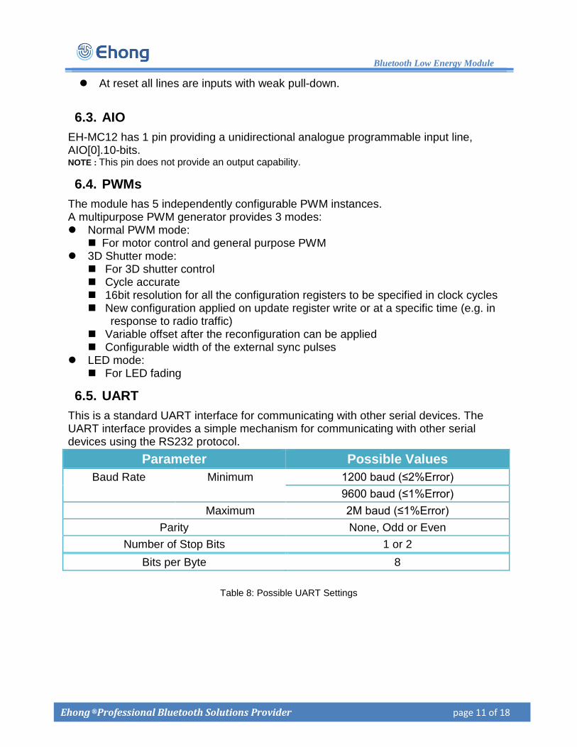
6.5. UART
This is a standard UART interface for communicating with other serial devices. The UART interface provides a simple mechanism for communicating with other serial devices using the RS232 protocol.
Table 8: Possible UART Settings
Parameter Possible Values
Baud Rate Minimum 1200 baud (≤2%Error)
9600 baud (≤1%Error)
Maximum 2M baud (≤1%Error)
Parity None, Odd or Even
Number of Stop Bits 1 or 2
Bits per Byte 8
EH-MC12
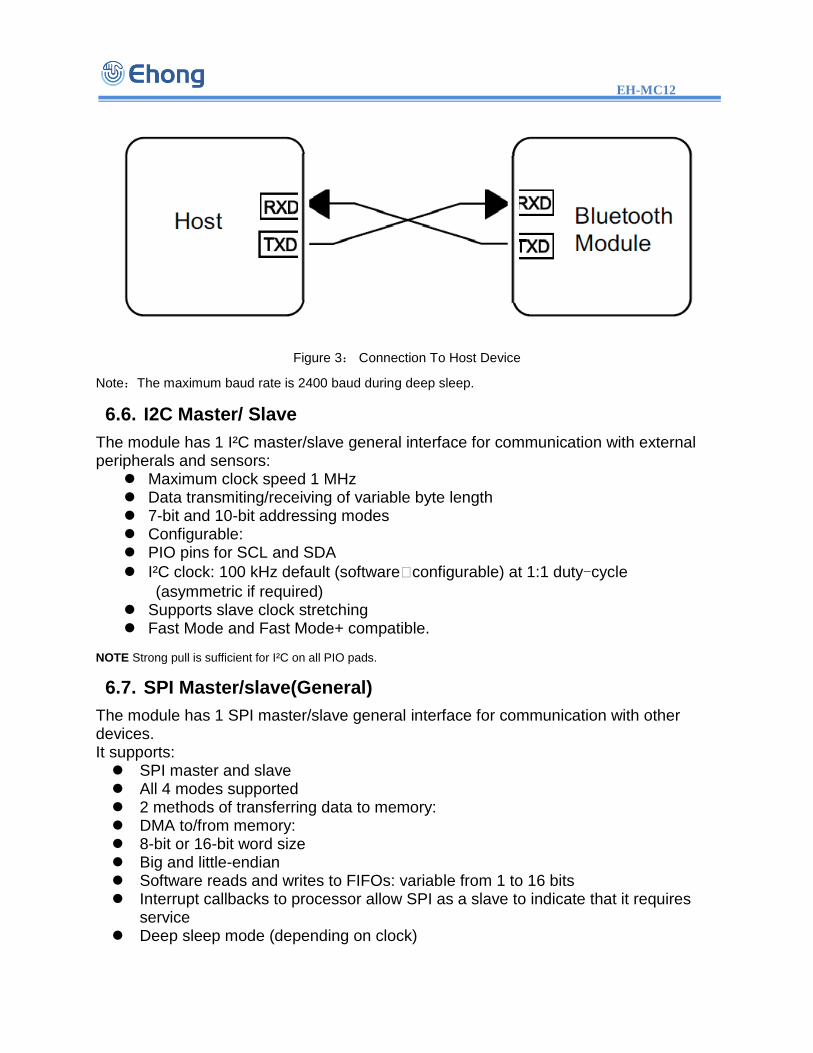
Figure 3: Connection To Host Device
Note:The maximum baud rate is 2400 baud during deep sleep.
6.6. I2C Master/ Slave
The module has 1 I²C master/slave general interface for communication with external peripherals and sensors:
Maximum clock speed 1 MHz Data transmiting/receiving of variable byte length 7-bit and 10-bit addressing modes Configurable: PIO pins for SCL and SDA
I²C clock: 100 kHz default (software�configurable) at 1:1 duty-cycle
(asymmetric if required) Supports slave clock stretching Fast Mode and Fast Mode+ compatible.
NOTE Strong pull is sufficient for I²C on all PIO pads.
6.7. SPI Master/slave(General)
The module has 1 SPI master/slave general interface for communication with other devices. It supports: SPI master and slave All 4 modes supported 2 methods of transferring data to memory: DMA to/from memory: 8-bit or 16-bit word size Big and little-endian Software reads and writes to FIFOs: variable from 1 to 16 bits Interrupt callbacks to processor allow SPI as a slave to indicate that it requires
service Deep sleep mode (depending on clock)

Bluetooth Low Energy Module
Ehong ® Professional Bluetooth Solutions Provider page 13 of 18
Figure 4: SPI interface
6.8. SPI Debug
The SPI Debug interface is chosen when SPI_PIO_S is high. The interface is used to program and debug the module. So always place test points or header on PCB for this interface and SPI_PIO_SEL.
6.9. Audio
Figure 5: Reference Design
NOTE Digital microphone and I²S input cannot be active at the same time. G.722 codec cannot encode and decode at the same time.
6.9.1. Digital Microphone
The module has 1 digital microphone input with: 1 or 2 Mbps sample rate Software selectable as left or right channel G.722 encoder or bypass option Audio routed to firmware only (not to I²S) Software supporting DMIC clock frequencies of 500 kHz, 1 MHz, 2 MHz, and 4 MH
EH-MC12
6.9.2. G.722 Codec
CSR1024 LGA has a G.722 Codec, featuring: Output: 48 kbps (optional 56 or 64 kbps) Input: 16 kHz/16bits (optional 8 kHz/8bits, 8 kHz/16bits and 16 kHz/8bits) Output produces 20 Byte blocks for easy GATT streaming NOTE: Analogue audio is not provided.
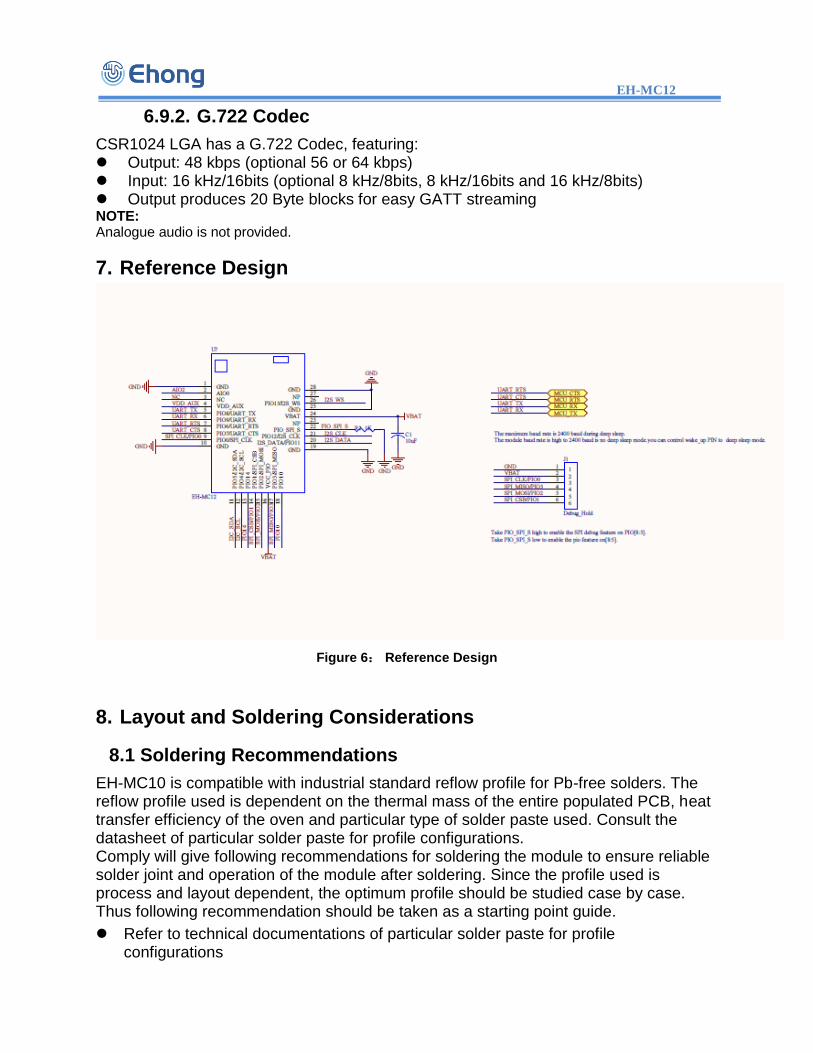
7. Reference Design
Figure 6: Reference Design
8. Layout and Soldering Considerations
8.1 Soldering Recommendations
EH-MC10 is compatible with industrial standard reflow profile for Pb-free solders. The reflow profile used is dependent on the thermal mass of the entire populated PCB, heat transfer efficiency of the oven and particular type of solder paste used. Consult the datasheet of particular solder paste for profile configurations. Comply will give following recommendations for soldering the module to ensure reliable solder joint and operation of the module after soldering. Since the profile used is process and layout dependent, the optimum profile should be studied case by case. Thus following recommendation should be taken as a starting point guide.
Refer to technical documentations of particular solder paste for profile configurations

Bluetooth Low Energy Module
Ehong ® Professional Bluetooth Solutions Provider page 15 of 18
Avoid using more than one flow.
Reliability of the solder joint and self-alignment of the component are dependent on the solder volume. Minimum of 150um stencil thickness is recommended.
Aperture size of the stencil should be 1:1 with the pad size.
A low residue, “no clean” solder paste should be used due to low mounted height of the component.
8.2 Layout Guidelines
For optimal performance of the antenna place the module at the corner of the PCB as shown in the figure 3. Do not place any metal (traces, components, battery etc.) within the clearance area of the antenna. Connect all the GND pins directly to a solid GND plane. Place the GND vias as close to the GND pins as possible. Use good layout practices to avoid any excessive noise coupling to signal lines or supply voltage lines. Avoid placing plastic or any other dielectric material closer than 6 mm from the antenna. Any dielectric closer than 6 mm from the antenna will detune the antenna to lower frequencies.
Figure 7: Clearance area of antenna

EH-MC12
9. Mechanical and PCB Footprint Characteristics
Figure 8:Physical Dimensions and Recommended Footprint (Unit: mm, Deviation:0.02mm)

Bluetooth Low Energy Module
Ehong ® Professional Bluetooth Solutions Provider page 17 of 18
10. Packaging
Figure 9: EH-MC10 Packaging(Pallet)
packaging for the pallet,one packaging quantity is 100 PCS。

EH-MC12
11. Soldering Recommendations EH-MC12 is compatible with industrial standard reflow profile for Pb-free solders. The reflow profile used is dependent on the thermal mass of the entire populated PCB, heat transfer efficiency of the oven and particular type of solder paste used. Consult the datasheet of particular solder paste for profile configurations. SMT stencil making requirements If Bluetooth module PIN pitch ≥ 0.25mm and other component PIN pitch ≥ 0.25mm,so you
choose SMT stencil thickness 0.15mm.
If Bluetooth module PIN pitch ≥ 0.25mm and other component PIN pitch ≤ 0.25mm,so you
choose SMT Ladder stencil Bluetooth module thickness 0.15mm other component thickness 0.13mm.
Solder pad open via ratio Length 1:1.2, width 1:1.
12. Contact Information
Sales: [email protected]
Technical support: [email protected]
Website: http://www.ehonglink.com
Tel: +86 21 64769993
Fax: +86 21 64765833
Address: Rm1505,1st,No.833 South Hongmei Rd, MinHang Dis, Shanghai, China