egr 2201 unit 4 mesh analysis read alexander & sadiku, sections 3.4 to 3.10. homework #4 and...
TRANSCRIPT

EGR 2201 Unit 4Mesh Analysis
Read Alexander & Sadiku, Sections 3.4 to 3.10.
Homework #4 and Lab #4 due next week.
Quiz next week.

Mesh Analysis
We’ve seen that nodal analysis is a systematic method for analyzing circuits. It’s based on Kirchhoff’s current law (KCL). It gives us the node voltages in a circuit. Once we have these node voltages, we can
find any other voltage or current. Mesh analysis is another systematic
method for analyzing circuits. It’s based on Kirchhoff’s voltage law (KVL). It gives us the mesh currents in a circuit. Once we have these mesh currents, we can
find any other current or voltage.

Meshes Versus Loops
Recall that a loop is any closed path in a circuit. Example: This circuit has six loops.
A mesh is a loop that does not contain any other loop within it. Example: The circuit above has three
meshes.
Mesh Currents Versus Branch Currents
A mesh current is a current that we imagine to travel around a mesh. You can imagine them to travel in either direction,
but most people assume clockwise. A branch current is a current that passes
through a branch (i.e., an element). If we know the values of all the mesh currents
in a circuit, we can compute any branch current.
In many diagrams, our textbook uses: Lowercase i and a looping arrow for mesh currents Uppercase I and a straight arrow for branch currents
Example: Mesh Currents Versus Branch Currents
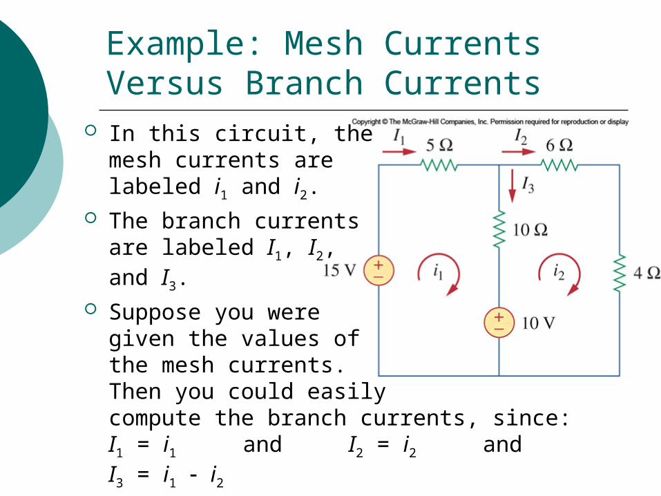
In this circuit, themesh currents are labeled i1 and i2.
The branch currents are labeled I1, I2, and I3.
Suppose you were given the values of the mesh currents. Then you could easily compute the branch currents, since:I1 = i1 and I2 = i2 and I3 = i1 i2
Steps in Performing Mesh Analysis on a Circuit with No Current Sources
Given a circuit with n meshes, without current sources, follow these steps:1. Assign mesh currents i1, i2, …, in to the n
meshes.2. Apply KVL to each of the n meshes. Use
Ohm’s law to express the voltages in terms of mesh currents. Then simplify the equations.
3. Solve the resulting n simultaneous equations to obtain the unknown mesh currents.
Example: Step 1 (Assign the Mesh Currents)
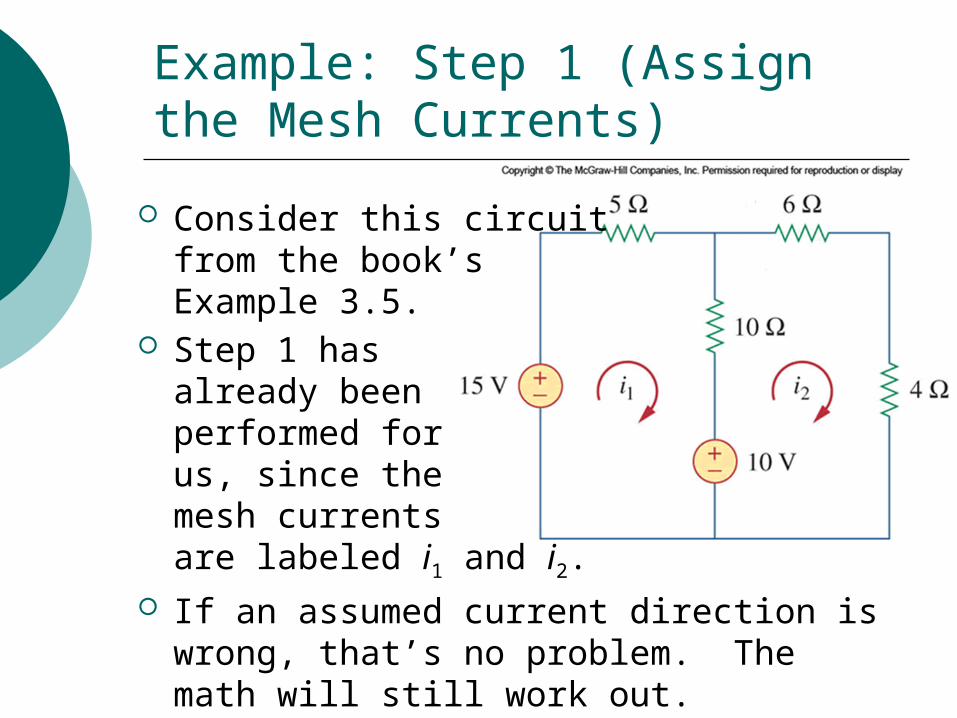
Consider this circuit from the book’s Example 3.5.
Step 1 has already been performed for us, since the mesh currents are labeled i1 and i2.
If an assumed current direction is wrong, that’s no problem. The math will still work out.

Apply KVL (and Ohm’s law) to mesh 1:
15 + 10i2 = 5i1 + 10i1 + 10
Apply KVL (and Ohm’s law) to mesh 2:
10 + 10i1 = 10i2 + 6i2 + 4i2
Example: Step 2 (Apply KVL)Part 1 of 2
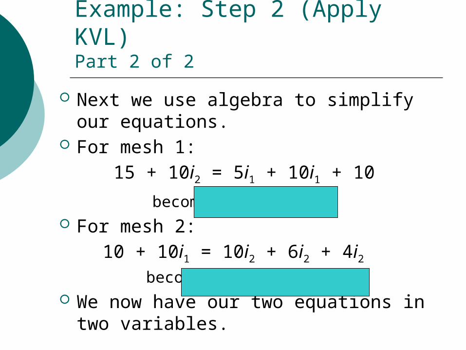
Next we use algebra to simplify our equations.
For mesh 1: 15 + 10i2 = 5i1 + 10i1 + 10
becomes For mesh 2: 10 + 10i1 = 10i2 + 6i2 + 4i2 becomes We now have our two equations in two
variables.
Example: Step 2 (Apply KVL)Part 2 of 2
Next we use any of our methods—substitution, Cramer’s rule, matrix inversion, MATLAB—to solve our two equations in two variables.
Using MATLAB, the solution to
isi1 = 1 A and i2 = 1 A
Example: Step 3 (Solve)
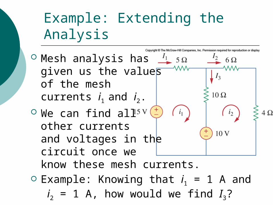
Mesh analysis hasgiven us the valuesof the mesh currents i1 and i2.
We can find all other currentsand voltages in the circuit once we know these mesh currents.
Example: Knowing that i1 = 1 A and i2 = 1 A, how would we find I3?
Example: Extending the Analysis
Review: Steps in Performing Mesh Analysis on a Circuit with No Current Sources
Given a circuit with n meshes, without current sources, follow these steps:1. Assign mesh currents i1, i2, …, in to the n
meshes.2. Apply KVL to each of the n meshes. Use
Ohm’s law to express the voltages in terms of mesh currents. Then simplify the equations.
3. Solve the resulting n simultaneous equations to obtain the unknown mesh currents.

Circuit Analysis with Simulation Software
Section 3.8 discusses computer software named PSpice, which lets you simulate circuits.
Sinclair’s computers don’t have PSpice installed, but we have a similar program named Multisim.
Both are based on open-source code named SPICE (Simulation Program with Integrated Circuit Emphasis), which was first written at the University of California, Berkeley in the 1970’s.
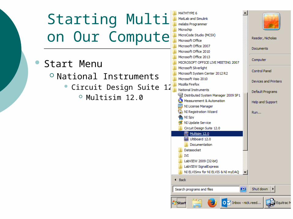
Starting Multisim on Our Computers
Start Menu National Instruments
Circuit Design Suite 12.0 Multisim 12.0
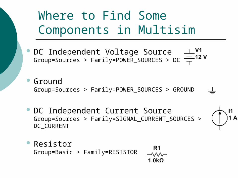
Where to Find Some Components in Multisim
DC Independent Voltage SourceGroup=Sources > Family=POWER_SOURCES > DC_POWER
GroundGroup=Sources > Family=POWER_SOURCES > GROUND
DC Independent Current SourceGroup=Sources > Family=SIGNAL_CURRENT_SOURCES > DC_CURRENT
ResistorGroup=Basic > Family=RESISTOR

Where to Find Some Measuring Instruments in Multisim
VoltmeterGroup=Indicators > Family=VOLTMETER> VOLTMETER_H
Shown is a horizontal voltmeter. Also available are a vertical version, as well as versions with the leads reversed.
AmmeterGroup=Indicators > Family=AMMETER> AMMETER_H
Shown is a horizontal ammeter. Also available are a vertical version, as well as versions with the leads reversed.
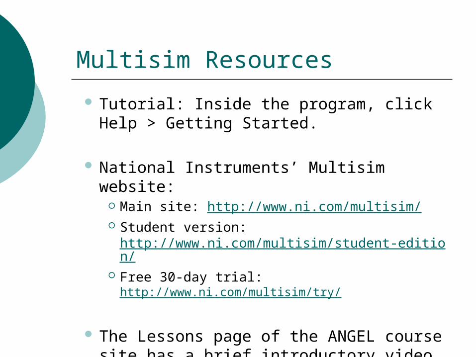
Multisim Resources
Tutorial: Inside the program, click Help > Getting Started.
National Instruments’ Multisim website: Main site: http://www.ni.com/multisim/ Student version:
http://www.ni.com/multisim/student-edition/ Free 30-day trial: http://www.ni.com/multisim/try/
The Lessons page of the ANGEL course site has a brief introductory video and handout from two other Sinclair instructors.
As described above, our procedure applies only to circuits without current sources.
But it’s not hard to extend the procedure to circuits with current sources.
The way you handle a current source depends on whether the source is located in only one mesh or is shared by two meshes….
What About Circuits with Current Sources?
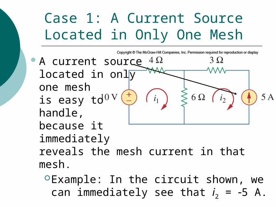
Case 1: A Current Source Located in Only One Mesh
A current source located in only one mesh is easy to handle, because itimmediately reveals the mesh current in that mesh.
Example: In the circuit shown, we can immediately see that i2 = 5 A.

Case 2: A Current Source Shared by Two Meshes
A current sourceshared by twomeshes is trickier.
To handle it, we create asupermesh by excluding the current source and any elements in series with it.

How to Handle a Supermesh
We apply KCL and KVL to the super-mesh to get twoequations.
Example: In thecircuit shown, KCL gives i2 = i1 +6
And KVL aroundthe supermesh gives 20 = 6i1 + 10i2 + 4i2
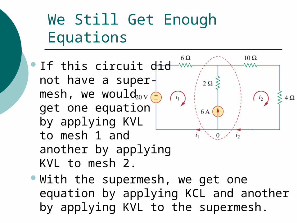
We Still Get Enough Equations
If this circuit didnot have a super-mesh, we would get one equation by applying KVLto mesh 1 and another by applying KVL to mesh 2.
With the supermesh, we get one equation by applying KCL and another by applying KVL to the supermesh.
Nodal Analysis and Mesh Analysis “By Inspection”
With practice, you’ll become good at writing down the set of simultaneous equations that describe a circuit using either nodal or mesh analysis.
As discussed in Section 3.6, there is a shortcut way to write down the equations quickly by looking at a circuit without even thinking in terms of KCL or KVL.
I won’t expect you to learn this shortcut method, but you can use it if you wish.
Which Should You Use: Nodal Analysis or Mesh Analysis?
Many circuits can be analyzed using either method, and both methods will give the same results.
But as discussed in Section 3.7, in some cases you’ll get the answer with less work if you’re smart about picking the better method for your circuit.
See next slide for examples.

Examples: Should You Use Nodal Analysis or Mesh Analysis?
For example:Use nodal analysis for circuits with
fewer nodes than meshes, and use mesh analysis for circuits with fewer meshes than nodes.
How many nodes does this circuit have?
How many meshes?

More Examples: Should You Use Nodal Analysis or Mesh Analysis?
As also noted in Section 3.7, mesh analysis cannot be applied to nonplanar circuits.
A circuit is planar if it can be drawn on a plane with no branches crossing each other; otherwise it is nonplanar.
We will only deal with planar circuits in this course.

Example of a Planar Circuit
This circuit, in which branches cross, can be redrawn with no crossing branches (as on the right below), so it is a planar circuit.
Crossing branches:No intersections here.
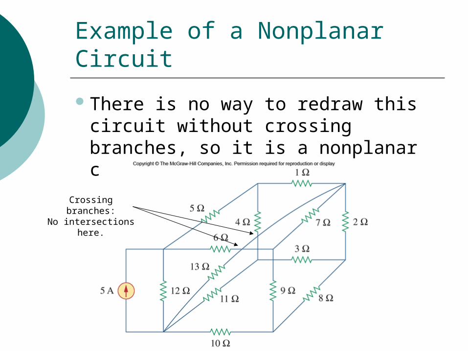
Example of a Nonplanar Circuit
There is no way to redraw this circuit without crossing branches, so it is a nonplanar circuit.
Crossing branches:No intersections here.