efficient network reachability analysis using a succinct ... · data plane, which in turn, is in...
TRANSCRIPT
This paper is included in the Proceedings of the 12th USENIX Symposium on Operating Systems Design
and Implementation (OSDI ’16).November 2–4, 2016 • Savannah, GA, USA
ISBN 978-1-931971-33-1
Open access to the Proceedings of the 12th USENIX Symposium on Operating Systems
Design and Implementation is sponsored by USENIX.
Efficient Network Reachability Analysis Using a Succinct Control Plane Representation
Seyed K. Fayaz and Tushar Sharma, Carnegie Mellon University; Ari Fogel, Intentionet; Ratul Mahajan, Microsoft Research; Todd Millstein, University of California, Los Angeles;
Vyas Sekar, Carnegie Mellon University; George Varghese, University of California, Los Angeles
https://www.usenix.org/conference/osdi16/technical-sessions/presentation/fayaz

Efficient Network Reachability Analysis usinga Succinct Control Plane Representation
Seyed K. Fayaz Tushar Sharma Ari Fogel∗
Ratul Mahajan† Todd Millstein‡ Vyas Sekar George Varghese‡
CMU ∗Intentionet †Microsoft Research ‡UCLA
Abstract— To guarantee network availability and se-curity, operators must ensure that their reachability poli-cies (e.g., A can or cannot talk to B) are correctly im-plemented. This is a difficult task due to the complexityof network configuration and the constant churn in a net-work’s environment, e.g., new route announcements ar-rive and links fail. Current network reachability analysistechniques are limited as they can only reason about thecurrent “incarnation” of the network, cannot analyze allconfiguration features, or are too slow to enable explo-ration of many environments. We build ERA, a tool forefficient reasoning about network reachability. Instead ofreasoning about individual incarnations of the network,ERA directly reasons about the network “control plane”that generates these incarnations. We address key expres-siveness and scalability challenges by building (i) a suc-cinct model for the network control plane (i.e., variousrouting protocols and their interactions), and (ii) a reper-toire of techniques for scalable (taking a few seconds fora network with > 1000 routers) exploration of this model.We have used ERA to successfully find both known andnew violations of a range of common intended polices.
1 IntroductionNetwork operators need to ensure the correct behavior oftheir networks. Violations of intended reachability poli-cies (e.g., “Can A talk to B?”) can compromise availabil-ity, security, and performance of the network. This riskhas inspired the field of network verification, which aimsto enable operators to systematically reason about theirnetworks [39].
Reasoning about a network is hard, as a real networkis in a perpetual churn: route advertisements arrive, linksfail, and routers need to be taken offline for maintenance.Nonetheless, an operator needs assurances on the networkbehaviors because a policy violation may be latent andoccur only in a certain future incarnation (e.g., a specificroute advertisement from a peering network may causedisconnection between A and B [6, 11]). Unfortunately,today operators do not have proper tools for efficient rea-soning about the network in different environments.
dataplaneat)metA B
dataplaneat)met+1dataplaneat)met+2
…
Networkcontrolplane
…
Environmentat)metRouters
configura)onfiles
Environmentat)met+1Environmentat)met+2
Figure 1: Reachability behavior of a network (e.g., Acan talk to B) is determined by its data plane, which,in turn, is the current incarnation of the control plane.
To highlight this challenge, it is useful to consider priorwork on network verification. A network is composedof a control plane, which configures the behavior of thedata plane, which in turn, is in charge of forwarding ac-tual packets (see Figure 1). The control plane, therefore,can be thought of as a program that takes configurationfiles and the current network environment (i.e., route ad-vertisements) and generates a data plane. The data planeis conceptually a program that takes a packet and its loca-tion (i.e., a router port) as input and outputs a packet at adifferent location. As a result, if we rest our analysis onthe data plane (e.g., Veriflow [29], HSA [28], NOD [36])and verify its behavior over its inputs (i.e., packets), weare inherently able to reason about only the current incar-nation of the control plane (i.e., the current data plane),and cannot say anything about the network behavior un-der a different environment.
While there is prior work on bug-finding and verifica-tion for the control plane, it suffers from critical limita-tions. Some tools focus on a single routing protocol (e.g.,BGP for Bagpipe [41] and rcc [18]) or a limited set ofrouting protocol features (e.g., ARC [21]). They can thusnot capture the behavior of the entire control plane that of-ten uses multiple routing protocols and sophisticated fea-tures [22,31,38]. On the other hand, Batfish [19] analyzesthe entire control plane in the context of a given environ-
USENIX Association 12th USENIX Symposium on Operating Systems Design and Implementation 217

ment, but it does so by simulating the behavior of individ-ual routing protocols to compute the resulting data plane.This simulation is expensive (see §9.2), which makes itprohibitive to iteratively use Batfish to analyze the impactof many environments.
What is critically missing today is the ability to ef-ficiently find network reachability bugs across multiplepossible environments. (§3 motivates this need using real-world examples.) Doing so requires reasoning about net-work reachability directly at the control plane level, with-out explicitly computing the data plane that manifests ineach environment. Such reasoning is challenging due tothe complexity of the control plane, which involves vari-ous routing protocols (e.g., BGP, OSPF, RIP) each with itsown intricacies (e.g., selecting best route to a destinationprefix is different for BGP and OSPF) and cross-protocolinteractions (e.g., route redistribution [32]).
We address these challenges in a tool called ERA (ef-ficient reachability analysis) by employing several syn-ergistic ideas. First, we design a unified control planemodel that succinctly captures the key behaviors of vari-ous routing protocols. In this model, a router is viewed asa function that accepts a route announcement as input andproduces a set of route announcements for its neighbors.Second, we use binary decision diagrams (BDDs) [30] tocompactly represent the route announcements that consti-tute a user-specified environment. Third, we shrink theBDD representation of route announcements by identify-ing equivalence classes of announcements that are treatedidentically by the given network [42]. Each equivalenceclass is given an integer index, and the reachability analy-sis is transformed to arithmetic operations directly on setsof these indices. Consequently, we take advantage of vec-torized instruction sets on commodity CPUs for fast com-putation of these set operations (§6).
ERA can be used to identify bugs in reachability poli-cies of the form “A can talk to B” as well as a widerange of common policies that are expressible in termsof reachability relationships, such as valley-free routingand blackhole-freeness (§7). Our implementation of ERAis available as an open source and extensible toolkit towhich new kinds of analysis can be added (§8).
We evaluate the utility of ERA in a range of real andsynthetic scenarios (§9.1). Across all scenarios, it suc-cessfully finds both new and known reachability viola-tions, which were otherwise hard to find using the stateof the art techniques. We also evaluate the scalability ofERA and find that it can handle a network with over 1,600routers in 6 seconds. Our evaluations show that our con-trol plane modeling and exploration techniques yield sig-nificant speedup.
2 Related WorkThere are several strands of related prior work.
Data plane analysis: Verifying the reachability be-havior of the data plane has been widely studied (e.g.,Anteater [37], Veriflow [29], HSA [28], NOD [36]). Theresult from such verification, however, is valid only for thespecific data plane being analyzed. There has also beenextensive work on testing the data plane (e.g., ATPG [43],Pingmesh [26]). Data plane verification and testing is fun-damentally limited, as a network is in a constant churn,which manifests itself as different data planes. For exam-ple, a single route advertisement can dramatically changethe network behavior (e.g., see [11]).
Control plane analysis: Moving from the data plane tothe control plane potentially enables more powerful anal-ysis, as the former is generated by the latter. However,prior work is limited due to supporting only a single rout-ing protocol (e.g., BGP in Bagpipe [41] and rcc [18]) or alimited set of routing protocol features (e.g., ARC [21]).Batfish [19] can reason about the entire control plane butits analysis is expensive because it simulates the individ-ual steps of each routing protocol. In contrast, ERA en-ables fast exploration using a succinct encoding of controlplane behavior.
Clean-slate control plane design: Metarouting [24],glue logic [33], and Propane [16] aim to build a correct-by-design control plane. While worthwhile in the longterm, these efforts cannot reason about existing networks.
To summarize, what is critically missing today is theability to efficiently explore the control plane involvingvarious routing protocols. We illustrate this need below.
3 Motivation: Reachability BugsWe motivate reasoning about multiple network incarna-tions using real reachability bugs encountered in a largecloud provider’s network. These bugs were latent andmanifested only under certain environments.
Maintenance-triggered: Some bugs stem from unex-pected interactions of different routing protocols and con-figuration directives. In this example (Figure 2), the in-teractions are between static routing and BGP. For redun-dancy, the operator’s goal was to have two paths betweenthe DCN (datacenter network) and the WAN (wide areanetwork), one through R1 and the other through R2. Oneday, the operator decided to temporarily bring down R2
for maintenance, which she thought was safe because ofthe assumed redundancy. However, as soon as R2 wasbrought down, the entire DCN was disconnected from theWAN (and the rest of the Internet).
218 12th USENIX Symposium on Operating Systems Design and Implementation USENIX Association

kawaguchi
1
Mgmt.Net.
M
R1
1.2.3.4
R2
WWAN 0.0.0.0/0Datacenter
DCN
Figure 2: A bug triggered by maintenance.
Manual investigation revealed thatR1 contained a static default routeip route 0.0.0.0/0 1.2.3.4 (here 1.2.3.4is the next-hop of the static route, which is the addressof the management network). Static routes to a prefixsupersede dynamic routes [5, 8]. Thus R1 preferred thestatic route over the default BGP route advertised by theWAN (shown in red). Since static routes are typically notpropagated to neighbors, R1 did not advertise the defaultroute to the DCN. Thus, the DCN was entirely dependenton R2 for external connectivity.
The bug inR1’s configuration was that the operator hadforgotten to type keywords to indicate that the static routebelonged to the management network, not data network.(These keywords were present inR2’s configuration.) Thebug was latent as long as R2 was up, but was triggeredwhen R2 was brought down.Announcement-triggered: In Figure 3, DCA had sev-eral services hosted inside the subprefixes of 10.10.0.0/16.Instead of announcing the individual subprefixes, R1 wasannouncing this aggregate prefix. DCB could reach theservices inside DCA through the WAN. As soon as a newservice with prefix 10.10.1.160/28 was launched insideDCA, all other services inside the /16 prefix became un-reachable from DCB .
bug_0500
1
WAN10.10.1.160/28Datacenter
DCA DCB
R1 R2
W
Figure 3: A bug triggered by a BGP announcement.
Investigation revealed two latent configuration bugsthat combined to create this outage: (1) R1 was not con-figured to filter 10.10.1.160/28 in its announcements tothe WAN; and (2) R2 was configured with an aggregateroute to 10.10.0.0/16 with DCB as the next hop. The re-sult of the first bug was that the /28 announcement reachedR2 through the WAN. Then, as a result of the second bug,the /16 aggregate route was activated at R2. This aggre-gate route, as a local route to router R2, took precedenceover the /16 being announced through the WAN. Whenthe aggregate route was activated, R2 started dropping alltraffic to the /16 except for traffic to the /28. These dropsare due to the sinkhole semantics of route aggregation—
Figure 4: A bug triggered by link failure.
the aggregating router drops packets for subprefixes forwhich it does not have an active route to prevent routingloops [34].1 Proper connectivity existed prior to the /28announcement because the /16 announcement from theWAN did not activate the aggregate route at R2.
Failure-triggered: In Figure 4, R1 and R2 were config-ured to announce prefix 10.10.0.0/16 that aggregated thesubprefixes announced by leaf routers (A1,A2,A3). Afterlink A2—B2 failed, WAN traffic destined to A2’s prefix(10.10.2.0/24) started getting blackholed (i.e., dropped) atR1 even though A2 had connectivity via B3 and R2.
This blackhole was created because R1 continued tomake the aggregate announcement after the failure of linkA2–B2, as it was still hearing announcements for the othertwo subprefixes corresponding to A1 and A3 (aggregateroutes are announced as long as there is at least one sub-prefix present). As a result, the WAN sent (some) trafficfor 10.10.2.0/24 toward R1. But R1 dropped those pack-ets per the sinkhole semantics (see above).
4 ERA OverviewIn this section, we present our approach and discuss thechallenges in realizing it. Our target is a (datacenter, en-terprise, or ISP) network of a realistic size (e.g., a few tohundreds of routers). As shown in Figure 5, our user is anetwork operator responsible for configuring routers. Theoperator has a set of intended reachability policies of theform “Router port A can talk to router port B” (as we willdiscuss in §7, several other practical policies are deriva-tives of “A can talk toB”). ERA allows operators to inputtheir assumptions on what the network’s environment willsend (e.g., based on relationship with peers/providers).It then analyzes the network’s behavior under these as-sumptions and checks whether the behavior satisfies theintended reachability policies. This process can then beiterated with other environmental assumptions, in order tocover a range of possible environments.
1For instance, if W announced the default route to R2, R2 wouldforward traffic for 10.10.2.2 to W, which may then forward them to R2(because R2 announces the aggregate /16 to W), and so on.
USENIX Association 12th USENIX Symposium on Operating Systems Design and Implementation 219

routerconfigura,ons
analysisresults(successorviola0on)
Operatorenvironmentassump,ons
controlplanemodel
modelexplora,on
ERA
reachabilitypolicies
networktopology
Figure 5: High-level vision of ERA.
4.1 Our ApproachHere we give the intuition behind our approach to controlplane analysis.
Relationship between data and control planes: Thedata plane takes as input a packet on a router portand moves the (possibly modified) packet to anotherport (on the same or a neighboring router). Thus, wecan think of the data plane as a function of the formDP : (pkt , port)→ (pkt , port). The data plane itself isgenerated by the control plane function given routers’configuration files, the network topology (i.e., whichrouter ports are inter-connected), and the current envi-ronment (which captures the route advertisements sentto the network by the “outside world”) of the network:CP : (env ,Topo,Configs)→ DP(.).
Reachability policies via control plane analysis: Sincepackets are forwarded by the data plane, it is natural tothink of an intended reachability policy φA→B as a pred-icate that indicates whether a given packet should be ableto reach from router port A to router port B. We say dataplane DP is policy-compliant if φA→B (pkt ,DP) evalu-ates to true for all A-to-B packets.
A seemingly natural approach for finding latent bugs isto produce the data plane associated with a given environ-ment and then check reachability on that data plane [19].However, this approach makes it prohibitively expensiveto iteratively check multiple environments (§9.2). Thisis because for each possible environment (of which thereare many), to compute the resulting data plane, we needto account for all low-level message passings and nuancesof routing protocols. Instead, we want to be able to reasonabout the network directly at the level of the control planeand without explicitly computing the data plane.
To this end, our insight is as follows. Rather than pro-ducing the data plane that results from a given environ-ment, we can analyze the control plane under that en-vironment to determine i) the routes that each router inthe network learns via its neighbors (e.g., a BGP adver-tisement) or its configuration file (e.g., static routes); andii) the best route when multiple routes to the same prefixare learned. We can then use this information to directly
e2e routers ports
1
R11 23
R24 5
R36 7
X YR498
10
Network Environment
routeadver1sement
Figure 6: X-to-Y reachability depends on routers con-figurations and the environment.
check reachability.An illustrative example: To visualize what it means toreason about reachability using control plane analysis,consider the example shown in Figure 6. Here we wantto see what traffic reaches from port X to port Y so thatwe can check whether it is policy-compliant. From thefigure we can see that to find the above traffic, we cantry to find the routes that traverse the opposite directionon each of the two paths. Let T i→j
Router (route) show theoutput of the configured router Router on its port j giventhe input route on its port i. (Intuitively, route can bethought of as an abstraction for a route advertisement.The following section will elaborate on this abstraction.)If we knew T (.), the answer would be:T2→1
R1(T5→4
R2(T10→8
R4(env))) ∪ T3→1
R1(T7→6
R3(T10→9
R4(env))).
The argument env here represents the assumptions thatthe user makes about the environment.
4.2 ChallengesControl plane-based reachability analysis requires us toaddress two key challenges:• An expressive and tractable control plane model: To
be expressive, this model needs to capture key behav-iors of diverse protocols (e.g., BGP, OSPF route adver-tisements). A naive model (e.g., capturing protocol-specific behaviors verbatim), while expressive, is im-practical because it will be too complex to explore. Onthe other extreme, a very high-level model (e.g., ig-noring protocol-specific behaviors altogether) may betractable to explore, but not expressive (e.g., BGP andOSPF have different ways of preferring routes).
• Scalable control plane exploration: Once we have acontrol plane model, we need the ability to efficientlyexplore the model with respect to the environment,in order to identify violations of intended reachabilitypolicies.We tackle these challenges in §5 and §6, respectively.
4.3 Scope and LimitationsERA’s analysis requires the user to provide assumptionson the environment (or defaults to assuming that the en-vironment makes all possible route announcements). Ifthese assumptions are incorrect or overly permissive, thenERA can produce false positives, identifying purportederrors that in fact will never arise in practice; e.g., a rep-
220 12th USENIX Symposium on Operating Systems Design and Implementation USENIX Association

utable ISP is not likely to hijack its peer’s traffic. ERA isdesigned to have no other source of false positives (i.e., itscontrol plane model is accurate). Though we have not for-mally proven this yet, empirically speaking, all the bugsthat ERA has identified were real bugs.
ERA also has several sources of false negatives. First,ERA will only find bugs under environments specified asinputs and cannot guarantee the absence of bugs under allenvironments (unless exhaustively iterated on all possibleenvironments). Second, certain classes of errors cannot befound by ERA by design. Specifically, ERA assumes thatrouting will converge and only analyzes this convergentstate, which is key to efficient exploration of the controlplane. Therefore convergence errors as well as reacha-bility errors in transient states of the network will not befound (e.g., [23, 25]).
Finally, while ERA supports most of the common con-figuration directives, our current implementation does notsupport certain directives such as regular expressions inrouting filters. Keeping up with configuration directivesis a software engineering challenge due to their large andgrowing universe. Such limitations, however, are not fun-damental to the design of ERA (unlike ARC [21], wherethe design itself cannot handle certain routing features).
As we will see in §9, ERA can find a large class of real-world bugs despite these limitations.
5 Modeling the Control PlaneWe now describe our model for the network control plane.It i) captures all routing protocols using a common ab-straction; ii) is expressive with respect to routing behav-iors of individual protocols; and iii) lends itself to scal-able exploration. At a high level, we identify key behav-iors of the control plane (e.g., route selection, route aggre-gation) and compactly encode them using binary decisiondiagrams (BDDs) [30].
Since the network control plane is a composition of thecontrol planes of individual routers, we break down theproblem of modeling the network control plane into mod-eling (i) the I/O unit of a router’s control plane (§5.1), and(ii) the processing logic of a router’s control plane (§5.2).
5.1 Route as the Model of Control Plane I/OA naive way of modeling the I/O unit of the control planeof a router is to use the actual specification of route ad-vertisements of different routing protocols, including theirlow-level details (e.g., keep-alive messages, sequencenumbers [3,9]). While expressive, such an I/O unit makesthe control plane model too cumbersome. Conversely, ifwe completely ignore differences across protocols to sim-plify our I/O unit model, such a model may not be expres-sive; e.g., it cannot capture the fact that if a router learns
route data structure
1
Administra,vedistance(4bits)
Protocola7ributes(87bits)
DstIP(32bits)
Dstmask(5bits)
Figure 7: route as the model of control plane I/O.two routes to the same destination prefix from two dif-ferent routing protocols, the one offered by the protocolthat has a smaller administrative distance (AD) will be se-lected [5,8]. (We will see an example bug scenario due tothis effect in §9.1.2, Figure 15b.)
To strike a balance between expressiveness andtractability, we introduce the notion of an abstract routeas a succinct yet expressive I/O unit for the control planemodel. Conceptually, a route mimics a route advertise-ment. It is a succinct bit-vector conveying key informa-tion in route advertisements that affects routing decisionsof a router (see Figure 7). While not fundamental to ourdesign, we have chosen a 128-bit vector to encode a routeto enable fast CPU operations as we will discuss in §6.2.To accommodate diverse routing protocols, a route unifieskey attributes of various protocols that affect a router’s be-haviors (i.e., administrative distance and protocol-specificroute attributes).2 To improve scalability, a route abstractsaway the low-level nuances of actual protocols (e.g., seq.numbers, acknowledgements).
The fields of our route abstraction are:• Destination IP and mask: Together, they represent the
destination prefix that the route advertises. To makea route compact, we store the mask in 5 bits (insteadof its naive storage in 32 bits). For completeness, Ap-pendix A shows the details of how we do this.• Administrative distance (AD): This is a numerical rep-
resentation of the routing protocol (e.g., BGP, OSPF)of the route such that ADA < ADB denotes routingprotocol A is preferred to protocol B.• Protocol attributes: This captures protocol-specific at-
tributes of the routing protocol represented by AD.For example, if the value of AD corresponds to BGP,the protocol attributes field encodes the BGP attributes(i.e., weight, local preference). To enable fast imple-mentation of route selection in our router model (thatwe will discuss in §5.2), we carefully encode the at-tributes so that preferring a route between two routesroute1 and route2 simply becomes a matter of choos-ing the smaller of two bit-vectors AD1 .attrs1 andAD2 .attrs2 when interpreted as unsigned integers (thesymbol . denotes concatenation of the AD and proto-col attributes fields of a route). For example, sinceroute selection in BGP involves checking a prioritizedlist of BGP attributes (e.g., first checking the weight,2Since our route model resembles routing messages in distance-
vector protocols, we accommodate link state protocols (e.g., OSPF) byletting the attributes refer to the routes output by the Dijkstra algorithm.
USENIX Association 12th USENIX Symposium on Operating Systems Design and Implementation 221
ANDwithsupportedprotocols
VinApplyinputfilters
ORwithroutesoriginatedbyrouter
ORwithredistributedroutes
ApplyoutputfiltersSelectbestrouteperdstprefix
ANDwithNEG.ofsta9croutes
ORwithaggregateroutes
Vout
1 2 3
456
7 8
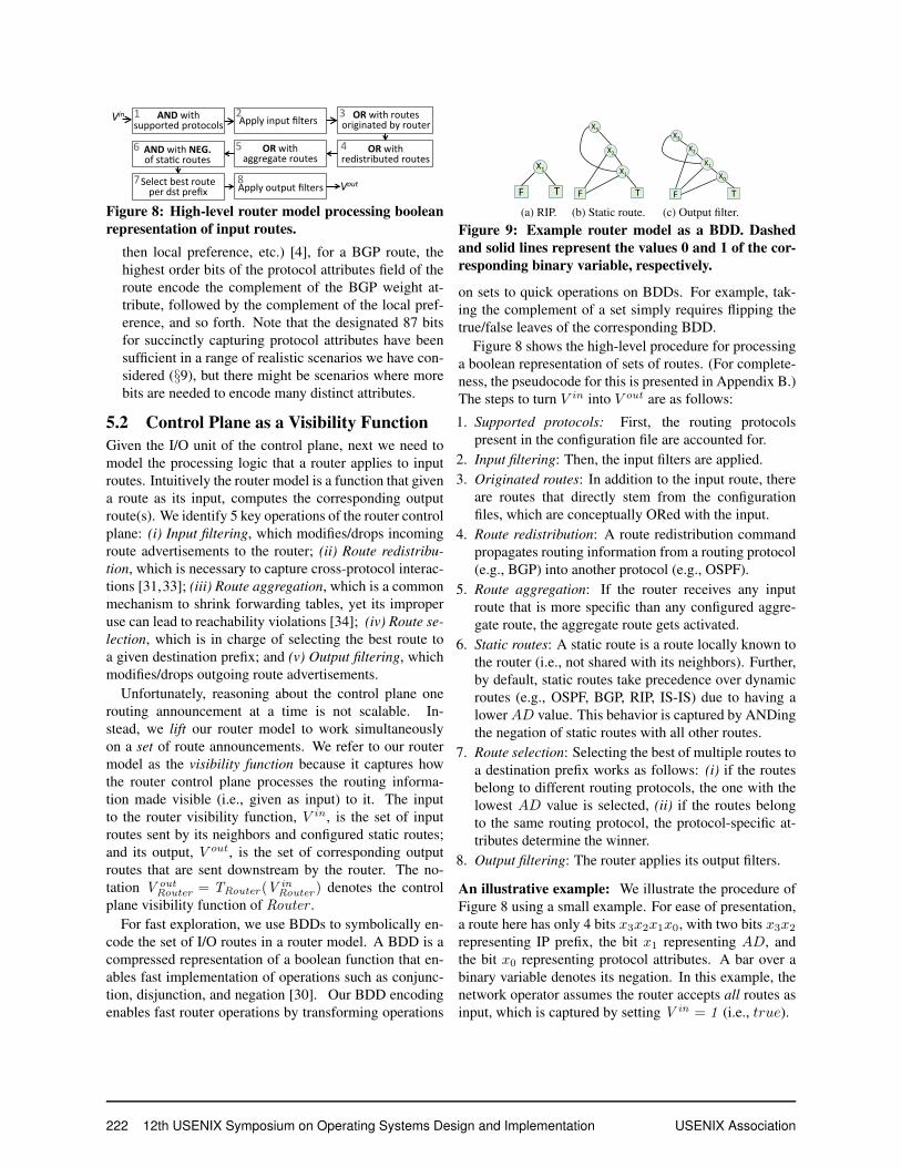
Figure 8: High-level router model processing booleanrepresentation of input routes.
then local preference, etc.) [4], for a BGP route, thehighest order bits of the protocol attributes field of theroute encode the complement of the BGP weight at-tribute, followed by the complement of the local pref-erence, and so forth. Note that the designated 87 bitsfor succinctly capturing protocol attributes have beensufficient in a range of realistic scenarios we have con-sidered (§9), but there might be scenarios where morebits are needed to encode many distinct attributes.
5.2 Control Plane as a Visibility FunctionGiven the I/O unit of the control plane, next we need tomodel the processing logic that a router applies to inputroutes. Intuitively the router model is a function that givena route as its input, computes the corresponding outputroute(s). We identify 5 key operations of the router controlplane: (i) Input filtering, which modifies/drops incomingroute advertisements to the router; (ii) Route redistribu-tion, which is necessary to capture cross-protocol interac-tions [31,33]; (iii) Route aggregation, which is a commonmechanism to shrink forwarding tables, yet its improperuse can lead to reachability violations [34]; (iv) Route se-lection, which is in charge of selecting the best route toa given destination prefix; and (v) Output filtering, whichmodifies/drops outgoing route advertisements.
Unfortunately, reasoning about the control plane onerouting announcement at a time is not scalable. In-stead, we lift our router model to work simultaneouslyon a set of route announcements. We refer to our routermodel as the visibility function because it captures howthe router control plane processes the routing informa-tion made visible (i.e., given as input) to it. The inputto the router visibility function, V in, is the set of inputroutes sent by its neighbors and configured static routes;and its output, V out, is the set of corresponding outputroutes that are sent downstream by the router. The no-tation V out
Router = TRouter (VinRouter ) denotes the control
plane visibility function of Router .For fast exploration, we use BDDs to symbolically en-
code the set of I/O routes in a router model. A BDD is acompressed representation of a boolean function that en-ables fast implementation of operations such as conjunc-tion, disjunction, and negation [30]. Our BDD encodingenables fast router operations by transforming operations
router as a BDD – step 0 of 3
1
F T
X1
(a) RIP.
router as a BDD – step 1 of 3
1
F T
X3
X2
X1
(b) Static route.
router as a BDD – step 3 of 3
1F T
X0
X1
X3X2
X1
F T
X0
(c) Output filter.
Figure 9: Example router model as a BDD. Dashedand solid lines represent the values 0 and 1 of the cor-responding binary variable, respectively.
on sets to quick operations on BDDs. For example, tak-ing the complement of a set simply requires flipping thetrue/false leaves of the corresponding BDD.
Figure 8 shows the high-level procedure for processinga boolean representation of sets of routes. (For complete-ness, the pseudocode for this is presented in Appendix B.)The steps to turn V in into V out are as follows:
1. Supported protocols: First, the routing protocolspresent in the configuration file are accounted for.
2. Input filtering: Then, the input filters are applied.3. Originated routes: In addition to the input route, there
are routes that directly stem from the configurationfiles, which are conceptually ORed with the input.
4. Route redistribution: A route redistribution commandpropagates routing information from a routing protocol(e.g., BGP) into another protocol (e.g., OSPF).
5. Route aggregation: If the router receives any inputroute that is more specific than any configured aggre-gate route, the aggregate route gets activated.
6. Static routes: A static route is a route locally known tothe router (i.e., not shared with its neighbors). Further,by default, static routes take precedence over dynamicroutes (e.g., OSPF, BGP, RIP, IS-IS) due to having alowerAD value. This behavior is captured by ANDingthe negation of static routes with all other routes.
7. Route selection: Selecting the best of multiple routes toa destination prefix works as follows: (i) if the routesbelong to different routing protocols, the one with thelowest AD value is selected, (ii) if the routes belongto the same routing protocol, the protocol-specific at-tributes determine the winner.
8. Output filtering: The router applies its output filters.
An illustrative example: We illustrate the procedure ofFigure 8 using a small example. For ease of presentation,a route here has only 4 bits x3x2x1x0, with two bits x3x2representing IP prefix, the bit x1 representing AD, andthe bit x0 representing protocol attributes. A bar over abinary variable denotes its negation. In this example, thenetwork operator assumes the router accepts all routes asinput, which is captured by setting V in = 1 (i.e., true).
222 12th USENIX Symposium on Operating Systems Design and Implementation USENIX Association

Suppose a router is configured with a static route andRIP, with AD values of 0 and 1, respectively. Figure 9shows the BDD representation of the router that has thefollowing four (simplified) configuration commands:• RIP, denoting the presence of RIP on the router, is cap-
tured by 1 ∧ x1 = x1, as shown in Figure 9a.• static 10/2: Since this static route overrides the
RIP routes with the same prefix, the resulting predicateis (x3 x2 )x1=x3 x1 ∨ x2 x1 . This is shown in Figure 9b.
• output filter: if RIP attribute is 0,
make it 1: The effect of the filter is to replace alloccurrences of x1 by x1 x0 . The resulting predicate isx3 x1 x0 ∨ x2 x1 x0 . This is captured in Figure 9c.Intuitively, the output V out = x3 x1 x0 ∨ x2 x1 x0 , sim-
plified to V out = (x3 ∨ x2 ) ∧ x1 x0 , represents the factthat given every environment as the input, the router out-puts RIP (noted by x1 ) with attribute 1 (noted by x0 ) andthe dest. prefix can be 00, 01, or 11 (noted by x3 ∨ x2 ).
In the following section, we will discuss how to reasonabout the reachability behaviors of the network by explor-ing the router model we developed in this section.
6 Exploring the ModelOur reachability analysis is based on an exploration of thecontrol plane model above. We first describe this explo-ration, and then describe how we leverage our BDD-basedencoding to devise a set of scalable exploration mech-anisms that use (i) the Karnaugh map, (ii) equivalenceclasses, and (iii) vectorized CPU instructions.
6.1 Exploration MethodWe present our approach to finding traffic reachable fromportA to portB using a representative example. Considerthe scenario shown in Figure 10. The red path is an A-to-B path involving routers RA, . . . ,Ri ,Ri+1 , . . . ,RB . Forease of presentation, in this example, there is only onepath from A to B; the general pseudocode presented inAppendix C accounts for all A-to-B paths.
To see the effect of the environment, consider router Ri ,which has three paths to router ports that face the outsideworld (namely, outside facing ports of routersR1,R3, andR5). Unless the operator makes a more specific assump-tion on an environment input (i.e., what route advertise-ments the outside world will send to the network), ERAstarts analysis using the boolean value true (representedby a BDD with only one leaf with the value true), whichrepresents the fact that every possible route are providedby the environment. On the other hand, if the operatoris able to make a more scoped assumption about the en-vironment (e.g., based on expected routes from a neigh-bor), the starting environment will reflect the assumption.
A to B reachability: steps 1 and 2
1
Ri
3
R3
R2
A
NetworkEnvironment
R1
R4R5
BRA RB
env1 env2
env3
Ri+1… …
PRj
…
Figure 10: Computing A to B reachability.Such assumptions can be encoded as a BDD that explic-itly includes the relevant variables on the assumed prefix,administrative distance, or attributes values of incomingroutes from the environment.
Computing traffic reachable from A to B involves thefollowing steps:1. Applying the effect of the environment: Every router on
a A-to-B path that has a topology path to the environ-ment, is affected by it. For router Ri in our examples,it means Ri receives the environment input Ein
i , where
Eini = T1(env1) ∨ T2(T3(env2)) ∨ T4(T5(env3))
2. Computing routes reachable from B to A: As we sawin §4.1, the key to computing traffic prefixes that reachfrom A to B using control plane analysis is to computewhat route prefixes are made visible from B back to A.Let assumedB show the input the operator assumesabout what port B receives from the environment. Forthe red path, this is captured by
reachA B =
TA(EinA ∨ . . . (Ti+1(E
ini+1 ∨ . . . TN (Ein
B ∨ assumedB) . . . )))
3. Extracting prefixes reachable from A to B: Since weare interested in route prefixes reachable from B to A,we eliminate binary variables in the route fields thatdo not correspond to prefix (i.e., AD and protocol at-tributes) in all boolean terms of reachA B .
4. Accounting for on-path static routes: In addition to theroutes that reach from B to A, which cause traffic toreach from A to B, there is potentially other traffic thatcan reach from A to B due to static routes configuredon on-path routers. This is because while a router doesnot advertise its static routes, activated static routes endup in its forwarding table. We account for such prefixesand OR them with the answer from step 3.
5. Applying ACL rules affecting A-to-B traffic: While arouter configuration file primarily includes directivesto configure the router control plane, it may include ac-cess control lists (ACLs) that restrict the actual trafficthat can pass through the data plane of the router. We,therefore, account for ACLs by taking the result of step4 and applying the ACLs of the on-path routers.
USENIX Association 12th USENIX Symposium on Operating Systems Design and Implementation 223

a4
a5 a6a7a1
a2
a3Y Z
X
Figure 11: Visualization of predicates X, Y, and Z interms of members of equivalence classes a1, . . . , a7.
Once traffic prefixes reachable from A to B are com-puted, the network is policy-compliant if the prefixesare equal to φA→B from §4.1. If φ is violated, ERAapplies the Karnaugh map [27] to the DNF representa-tion of the violating routes to provide the human oper-ator with fewer distinct items to investigate (§4.1); e.g.,instead of reporting distinct prefixes 10.20.0.0/17 and10.20.128.0/17 as violations, ERA summarizes and out-puts them as 10.20.0.0/16.
The process above finds policy violations in the con-text of a single set of environmental assumptions. Theuser can iterate multiple times with different assumptionsin order to expose more errors. Conceptually, each itera-tion of ERA over a BDD input analyzes a set of concreteenvironments for which the network has an identical be-havior. The analysis implicitly identifies this set duringexploration, by accumulating constraints from the visibil-ity function of each router in the network. Thus, the num-ber of iterations needed for exhaustive exploration usingERA is far less than those needed with data plane basedanalysis tools such as Batfish.
6.2 Scalability OptimizationsTo build an interactive tool for network operators, we wantERA to be able to compute A− to−B reachability in nomore than a few seconds. Even with the tractable controlplane model that we developed in §5, a naive implementa-tion of the exploration mechanism outlined in §6.1 fails tosatisfy our goal. This is because of the very large range ofpossible environments. Here we present three techniquesto scale control plane exploration.
Minimizing collection of routes with the K-map: Asa first step, to minimize the binary representation of therouter I/O, we apply the Karnaugh map (K-map), whichis a common technique in circuit design [27].
Finding equivalence classes: Performing computations(e.g., conjunction and disjunction) on boolean representa-tion of a real control plane is cumbersome. For example,the same or similar destination prefixes may appear onmultiple routers. As such, if we encode prefixes naively,this may slow down control plane exploration.
Given this observation, before performing reachabilityanalysis, ERA gets rid of redundant data by finding equiv-alence classes of routes which are treated identically by
{0,1,4} 1 0 0 1 1
{1,3} 0 1 0 1 0OR 1 1 0 1 1 {0,1,3,4}∪
(a) Set union using OR.
1 0 0 1 1
0 1 0 1 0AND 0 0 0 1 0 {1}
{0,1,4}
{1,3}∩
(b) Set intersection using AND.
Figure 12: Fast ∪ and ∩ of two sets of integers.
the network, using which the data can be rebuilt [42].The advantage of doing so is that now performing dis-junction and conjunction on boolean terms boils down todoing union and intersection on sets of integers (known asatomic predicates [42]). These integers are the indices ofthe equivalence classes. We illustrate this technique usingan example. Suppose we need to compute the conjunctionof the boolean termsX , Y , and Z (e.g., representing threeroutes). Instead of naively computing the conjunction onthe raw boolean form of these terms, we do the following:1. Express each term in terms of equivalence classes as
depicted in Figure 11; e.g., X = a2 ∨ a5 ∨ a6 ∨ a7.2. Represent each term using the indices of members of
equivalence classes, e.g., X is the union of members2, 5, 6, and 7. (This way, irrespective of how bulkythe raw form of term ai might be, it is represented byinteger value i.)
3. To compute X ∧ Y ∧ Z, intersect the sets of theircorresponding indices: {1, 5, 6, 7} ∩ {1, 4, 5, 7} ∩{3, 4, 6, 7} = {7}, which indicates the answer toX ∧ Y ∧ Z is a7.
Implementing fast set operations: As we saw above,using equivalence classes, reachability analysis involvescomputing union and intersection of sets of integers. Weleverage vectorized instructions on recent processors toperform fast set union and intersection of two sets of in-tegers (i.e., the indices of the equivalence classes). Theintuition is simple: if a set of integers is represented as abit vector where each bit represents the presence/absenceof the corresponding value, then the union (intersection)of two sets of integers is the bit-wise OR (AND) of thetwo bit vectors.
Figure 12 shows this approach using an example. In ourimplementation, we use instructions on 256-bit vectors inour Intel AVX2 implementation [13].
7 Going beyond ReachabilityBuilding on basic A-to-B reachability, ERA can be usedto check a wider range of policies. In §9, we will discussscenarios involving these policies.Valley-free routing: Operators often want to implement“valley-free” routing [20], which means that traffic from aneighboring peer or provider must not reach another suchneighbor. This condition is a form of reachability policythat ERA can easily check.
224 12th USENIX Symposium on Operating Systems Design and Implementation USENIX Association
Equivalence of two routers: Operators often use multi-ple routers to provide identical connectivity for fault toler-ance. Checking if they are identically configured (e.g., us-ing configuration syntax) is hard because the routers maybe from different vendors and many aspects of the con-figuration (e.g., interface IP addresses) can legitimatelydiffer across routers of even the same vendor. To checksemantic equivalence of two routers’ policies, we use thefollowing property of BDDs: if two boolean functions de-fined over n boolean variables are equivalent (i.e., theygenerate the same output for the same input), their Re-duced Ordered BDDs (ROBDDs) are identical [17]. Inour implementation, we check the equality of the ad-jacency matrix representations of the BDDs of the twofunctions, which takes O(n2 ). In contrast, a brute forcemethod will take O(2 n).Blackhole-freeness: A blackhole is a situation where arouter unintentionally drops traffic. The blackholed trafficfrom A to B is the complement of the reachable traffic:blackholeA B = reachabilityA B . Note that computingblackholes by ERA having computed reachability takesO(1), as the negation of a BDD is the same BDD with itstwo leaves (corresponding to true and false) flipped.Waypointing: Operators may want traffic from A to Bto go through an intended sequence of routers (e.g., toenforce advanced service chaining policies [15,35]). ERAchecks waypointing by explicitly checking whether trafficreachable from A to B goes through the intended routers.Loop-freeness: ERA can find permanent forward-ing loops (e.g., created by static or aggregate routes—see Figure13c in §9.1) by checking whether the samerouter port appears twice in the reachability result.
8 ImplementationOur implementation of ERA [1] supports several config-uration languages (e.g., Cisco IOS, JunOS, Arista). Ituses Batfish’s configuration parser, which normalizes avendor-specific configurations to vendor-agnostic format.ERA, then, uses this vendor-agnostic format as input.We implement the control plane model, the K-map, andatomic predicates in Java. To operate on BDDs, we usethe JDD library [7]. We implement our fast set intersec-tion and union algorithms in C using Intel AVX2, whichexpands traditional integer instructions to 256 bits [13].A natural question might be how much effort it takes to
add support for various routing protocols to ERA. In ourexperience, this effort is minimal. It took two of the au-thors a few hours to model the common routing protocolsbecause of two reasons. First, there are fewer than 10common routing protocols (e.g., BGP, OSPF, RIP, IS-IS).Second, for each protocol, the key insight for creating the
Ex 2: Back-up link ac0va0on due to route redist.
1
C
A B
X
BGP
1.WewantA-XandB-Xtobetheprimaryandbackuplinks,respec@vely.
ISPCustomernetwork
2.At!met1:OnAandB,sta@croutesareredistributedintoBGP,sothattheISPcanadver@sethemtotherestofthe Internet.B-Xactsasaprimary linksinceweforgottoadjustthedefaultADvaluesofBGPandsta@croutesonB.
ExamplebyFranckLeetal.,CoNext’08
3.At!met2:Theadminfixestheproblembywithdrawingthesta@crouteonB(orbyoverwri@ngthedefaultADvalueofsta@croutestofixtheproblemisfixed).
(a) Violation of way-pointing [32].
Ex. 3: Blackhole due to route aggrega4on
1
A
B C
10.1.2.0/24
10.1.3.0/24
1. BothBandCareconfiguredtoannounceaggregateroute10.1.2.0/23toA.
ExamplebyFranckLeetal.,CoNext’11
2.OneofB’sinterfacesfails,butBconHnuestoannouncetheaggregateroute.
3.Amaysendpacket’sdesHnedto10.1.2.0/24toB,whichBwilldrop.Query:IsthereanynegaHveroutesuchthat:
NOT(route)∈TBàneighbor(route)
(b) Black-hole [34].
Ex. 4: Permanent loop due to route aggrega4on
1
X
Y
1.ISPadver.sesthedefaultroutetoenterprisenetwork.
0.0.0.0/0
ExamplebyFranckLeetal.,CoNext’11
ISP
EnterpriseNetwork
3.Enterprisenetwork,however,adver.sestheaggregateroute128.2.0.0/16toISP.
10.2.0.0/16
2.Enterprisenetworkhasnexthopsonlyfor128.2.1.0/24 and 128.2.2.0/24.
4. ISPwill send trafficwith des.na.on128.3.0.0/24 to enterprise network. Thetrafficwilltrapinaloop.
Query:Isthereanynega.verouteroutesuchthat:RIBYisastrictsubsetofTYàneighbor(route)
10.2.1.0/24
10.2.2.0/24
(c) Permanent loop [34].
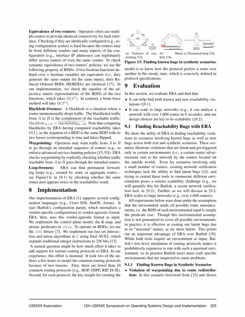
Figure 13: Finding known bugs in synthetic scenarios.
model is to know how the protocol prefers a route overanother in the steady state, which is concisely defined inprotocol specifications.
9 EvaluationIn this section, we evaluate ERA and find that:• It can help find both known and new reachability vio-
lations (§9.1).• It can scale to large networks (e.g., it can analyze a
network with over 1,600 routes in 6 seconds), and ourdesign choices are key to its scalability (§9.2);
9.1 Finding Reachability Bugs with ERAWe show the utility of ERA in finding reachability viola-tions in scenarios involving known bugs as well as newbugs across both real and synthetic scenarios. These sce-narios illustrate violations that are latent and get triggeredonly in certain environments (i.e., a certain router adver-tisement sent to the network by the routers located intthe outside world). Even for scenarios involving onlya small number of routers, existing network verificationtechniques lack the ability to find latent bugs (§2), andtrying to extend these tools to enumerate different envi-ronments poses a serious scalability challenge (e.g., wewill quantify this for Batfish, a recent network verifica-tion tool, in §9.2). Further, as we will discuss in §9.2,ERA scales to large networks (e.g., over 1,600 routers).
All experiments below were done under the assumptionthat the environment sends all possible route announce-ments, i.e. the BDD of each environmental input is simplythe predicate true. Though this environmental assump-tion is not guaranteed to cover all possible environments,in practice it is effective at rooting out latent bugs dueto its “maximal” nature, as we show below. This pointsout an important advantage of ERA over Batfish [19].While both tools require an environment as input, Bat-fish’s low-level simulation of routing protocols makes itprohibitively expensive to run with such a maximal envi-ronment, so in practice Batfish users must craft specificenvironments that are suspected to cause problems.
9.1.1 Finding Known Bugs in Synthetic Scenarios• Violation of waypointing due to route redistribu-
tion: In this scenario borrowed from [32] and shown
USENIX Association 12th USENIX Symposium on Operating Systems Design and Implementation 225

in Figure 13a, the customer wants to waypoint its traf-fic through X −A− C and use X − B − C as thebackup path. However, static routes configured onrouters A and B are redistributed into BGP, and theISP advertises them into the rest of the Internet. As aresult, B −X acts as a primary link. (One way to pre-vent this would be for the customer to adjust the defaultAD values of BGP and static routes on B.)
• Blackhole due to route aggregation: In this scenarioborrowed from [34] and shown in Figure 13b, bothrouters B and C are configured to announce aggregateroute 10.1.2.0/23 to router A. After the marked inter-face of B fails, B continues to announce the aggre-gate route, which causes A to send packets destined to10.1.2.0/24 to B. B will drop this traffic, as the its linkto the 10.1.2.0/24 subnetwork is down.
• Permanent loop due to route aggregation: In thisscenario borrowed from [34] and shown in Figure 13c,the ISP router X advertises the default route 0.0.0.0/0to router Y . Even though Y has connectivity to only10.2.1.0/24 and 10.2.2.0/24, it has been configured toadvertise to the ISP the aggregate route for the entire10.2.0.0/16 prefix. Now since 10.3.0.0/24 is as sub-prefix of 10.2.0.0/16, the ISP may send traffic to des-tination prefix 10.3.0.0/24 to Y . Consequently, sinceY does not know how to reach 10.3.0.0/24, this trafficwill match its default route entry and be bounced backto the ISP. This traffic, therefore, will trap in a perma-nent loop between X and Y .To further evaluate the effectiveness of ERA, we did
a red team-blue team exercise. In each scenario, the redteam introduced misconfigurations that cause a reachabil-ity violation unbeknownst to the blue team. Then the blueteam uses ERA to check whether the intended policy isviolated. Across all scenarios, the blue team successfullyfound the violation. Here is a summary of the scenarios:• Violation of waypointing: In Figure 14a, the intended
policy is to ensure traffic originating from network Edestined to network C goes through path E − B − C(so that it is scrubbed by the firewall). However, thispolicy is violated because router E receives the pre-fix of network C from both routers B and D, whichmeans NetE → NetC traffic may go through pathE −D − C skipping the firewall. The root cause ofthe problem was the fact that none of routers C, D, orE filtered the route advertisement for the 10.1.1.0/24prefix on the E −D − C path.
• Violation of valley-free routing: In Figure 14b,B andE are providers for C, which in turn, is a providerfor D. A missing export filter on C caused C to ad-vertise the prefix for NetE to B. This is a violation
B
EC
D
BGP
BGP
BGP
BGP
WAYPOINTING
NetworkOperatorwantsthedirec=ontobeC-B-EDwasmisconfiguredanddidn’tfilterBGPtraffictogoto10.1.1.0/24Itresultedintrafficgoingfrombothdirec=ons
NetC NetEFW10.1.1.0/24
(a) Violation of waypointing via B.
C
B E
D
NetD,NetE
NetD
NetE
NetB NetE
ValleyFree
1. B,EareproviderstoC.CisprovidertoD2. BGPisconfiguredinallrouters3.DisadverAsedtoEthroughC4.CismisconfiguredandadverAsesEtoBinsteadofjustD.5.Violatesvalleyfreeproperty
NetD
NetB
NetD
(b) Not valley-free.
B
A D
C
Isola+on
10.10.10.0/24
10.10.20.0/24 10.10.30.0/24
10.10.40.0/24BGP
BGP
OSPF
Redist.OSPFàBGP
A,BarepartofanetworkwhichusesonlyBGP.C,DarepartofanetworkwhichusesonlyOSPF.DwasmisconfiguredtoredistributeOSPFtoBGPThisresultedintheC,Dcommunica+ngwhichviolatedisola+onproperty
OSPF
(c) Violation of isolation between{A,B} and {C ,D}.
C
B
D
PrefixlistErrors/BasicReachability
10.10.0.0/16
10.20.0.0/16
10.10.0.0/16
Goal-A(consumer)needstoreachP(provider)D,B,CrunBGPChasaprefixlisttoletthrough2routesforbgpBwasmisconfiguredtoletonly1routethroughforbgpNoonenoLcesbecauseAcansLllreachPthroughC-DButifCorC-DfallsthenweloseconnecLvityto2.2.0.0/16duetothebug
Provider
A
10.10.0.0/1610.20.0.0/16
Client
(d) Misconfigured backup pathD − B −A.
Figure 14: Finding known bugs in synthetic scenariosusing the red-blue teams exercise.
of the valley-free routing property, specifically, due tocustomer C providing connectivity between two of itsproviders, namely, B and E.• Violation of intended isolation: In Figure 14c, we
want the traffic from segments {A,B} (running BGP)and {C ,D} (running OSPF) to remain isolated fromeach other. However, this policy is violated due to amisconfiguration on C whereby OSPF is redistributedinto BGP, that will allow traffic from {A,B} to reach{C ,D}.• Misconfigured backup path: In Figure 14d, the client
has two /16 networks connected to A and intends tomaintain two paths to the provider to ensure reachabil-ity in case of failure on one of them. This policy is vio-lated because of an incorrect filter configured onB thatdrops the advertisement for the 10.20.0.0/16 network.As a result, if path D − C −A fails, the 10.20.0.0/16network will be unreachable from the provider.
9.1.2 Finding New Bugs in Synthetic Scenarios
Finding reachability bugs in hybrid networks: Oper-ators may prefer to opt for a hybrid network, which in-volves deploying SDN alongside traditional network rout-ing infrastructure for scalability and fault tolerance [40].Next we show how ERA can find policy violations arisingin such hybrid deployments.
Fibbing [40] is a recent method to allow an operatorto use an SDN controller to flexibly enforce way-pointingpolicies in a network running vanilla OSPF. The key prim-itive is “fibbing” whereby the SDN controller pretends tobe a neighboring router and makes fake route advertise-ments with carefully crafted costs. For example, con-sider the network of Figure 15a, where links are anno-tated with their OSPF weights. If we run OSPF, both
226 12th USENIX Symposium on Operating Systems Design and Implementation USENIX Association
Fibbing bug due to aggrega.on on R2
1
R2
R3
R4
R5
D1
D2
S1
S2
R1
5 5
22
3 F 21
(a) Route aggregation on R2.
Fibbing bug due to bgp bea.ng ospf on R1
1
R1
R2
R3
R4
OSPF
S
5 3
12D
R5
F 11
OSPF
BGP
BGPBGP
OSPFOSPF
(b) Cross-protocol effects.
Figure 15: New bugs in a synthetic scenario involvinghybrid (i.e., SDN-traditional) networks.
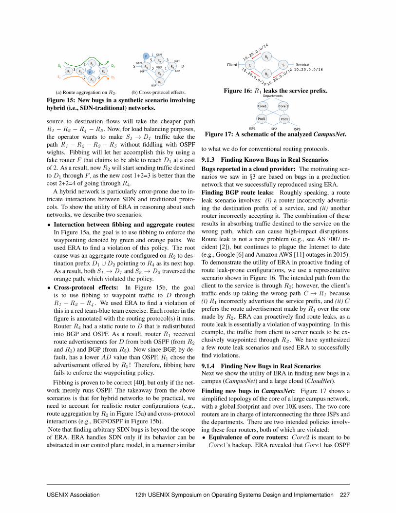
source to destination flows will take the cheaper pathR1 − R2 − R4 − R5 . Now, for load balancing purposes,the operator wants to make S1 → D1 traffic take thepath R1 − R2 − R3 − R5 without fiddling with OSPFwights. Fibbing will let her accomplish this by using afake router F that claims to be able to reach D1 at a costof 2. As a result, nowR2 will start sending traffic destinedto D1 through F , as the new cost 1+2=3 is better than thecost 2+2=4 of going through R4.
A hybrid network is particularly error-prone due to in-tricate interactions between SDN and traditional proto-cols. To show the utility of ERA in reasoning about suchnetworks, we describe two scenarios:
• Interaction between fibbing and aggregate routes:In Figure 15a, the goal is to use fibbing to enforce thewaypointing denoted by green and orange paths. Weused ERA to find a violation of this policy. The rootcause was an aggregate route configured on R2 to des-tination prefix D1 ∪D2 pointing to R4 as its next hop.As a result, both S1 → D1 and S2 → D2 traversed theorange path, which violated the policy.
• Cross-protocol effects: In Figure 15b, the goalis to use fibbing to waypoint traffic to D throughR1 − R2 − R4 . We used ERA to find a violation ofthis in a red team-blue team exercise. Each router in thefigure is annotated with the routing protocol(s) it runs.Router R4 had a static route to D that is redistributedinto BGP and OSPF. As a result, router R1 receivedroute advertisements for D from both OSPF (from R2
and R3) and BGP (from R5). Now since BGP, by de-fault, has a lower AD value than OSPF, R1 chose theadvertisement offered by R5! Therefore, fibbing herefails to enforce the waypointing policy.
Fibbing is proven to be correct [40], but only if the net-work merely runs OSPF. The takeaway from the abovescenarios is that for hybrid networks to be practical, weneed to account for realistic router configurations (e.g.,route aggregation byR2 in Figure 15a) and cross-protocolinteractions (e.g., BGP/OSPF in Figure 15b).Note that finding arbitrary SDN bugs is beyond the scopeof ERA. ERA handles SDN only if its behavior can beabstracted in our control plane model, in a manner similar
Route leak
1
C
R1
R210.20.0.0/16
SClient Service
Figure 16: R1 leaks the service prefix.SimplifiedviewofCMUNetwork
Core1 Core2
ISP1 ISP2 ISP3
Departments
1
• (Assumed)policy1:Core0andCore255aremeanttobe“equivalent”inthatifoneofthemfails,thereachabilityacrossnetowrkremainsunchanged.
• (Assumed)policy2:POD-I-CYHandPOD-I-NHaremeanttobe“equivalent”inthattheyimplementthesamepeeringpolicieswiththeISPs.
Pod1 Pod2
Figure 17: A schematic of the analyzed CampusNet.
to what we do for conventional routing protocols.
9.1.3 Finding Known Bugs in Real ScenariosBugs reported in a cloud provider: The motivating sce-narios we saw in §3 are based on bugs in a productionnetwork that we successfully reproduced using ERA.Finding BGP route leaks: Roughly speaking, a routeleak scenario involves: (i) a router incorrectly advertis-ing the destination prefix of a service, and (ii) anotherrouter incorrectly accepting it. The combination of theseresults in absorbing traffic destined to the service on thewrong path, which can cause high-impact disruptions.Route leak is not a new problem (e.g., see AS 7007 in-cident [2]), but continues to plague the Internet to date(e.g., Google [6] and Amazon AWS [11] outages in 2015).To demonstrate the utility of ERA in proactive finding ofroute leak-prone configurations, we use a representativescenario shown in Figure 16. The intended path from theclient to the service is through R2; however, the client’straffic ends up taking the wrong path C → R1 because(i) R1 incorrectly advertises the service prefix, and (ii) Cprefers the route advertisement made by R1 over the onemade by R2. ERA can proactively find route leaks, as aroute leak is essentially a violation of waypointing. In thisexample, the traffic from client to server needs to be ex-clusively waypointed through R2 . We have synthesizeda few route leak scenarios and used ERA to successfullyfind violations.
9.1.4 Finding New Bugs in Real ScenariosNext we show the utility of ERA in finding new bugs in acampus (CampusNet) and a large cloud (CloudNet).
Finding new bugs in CampusNet: Figure 17 shows asimplified topology of the core of a large campus network,with a global footprint and over 10K users. The two corerouters are in charge of interconnecting the three ISPs andthe departments. There are two intended policies involv-ing these four routers, both of which are violated:• Equivalence of core routers: Core2 is meant to beCore1’s backup. ERA revealed that Core1 has OSPF
USENIX Association 12th USENIX Symposium on Operating Systems Design and Implementation 227

configured on one of its interfaces, which is missing onCore2. As a result, ifCore1 fails, the departments thatrely on OSPF will be disconnected from the Internet.
• Equivalence of pod routers: Pod1 and Pod2, con-necting the campus to the Internet, are both connectedto ISP2 with the intention that link Pod1 − ISP2 isactive and Pod2 − ISP2 is its backup. ERA revealedthat the ACLs on Pod1 and Pod2 affecting their re-spective links with ISP2 are different. Specifically,Pod2 has more restrictive ACLs than Pod1. Thismeans if link Pod1 − ISP2 fails, a subset of campus-to-ISP2 traffic will be mistakenly dropped by Pod2.
Finding new bugs in CloudNet: We used ERA to checkequivalence of same-tier routers (analogous to routers R1
andR2 in Figure 2) on configurations of seven productiondatacenters of a large cloud provider. ERA revealed thatseven routers in two datacenters had a total of 19 staticroutes responsible for violations of equivalence policies.The operators later removed all of these violating routes.
9.2 Scalability of ERA
Testbed: We run our scalability evaluation experimentson a desktop machine (4-core 3.50GHz, 16GB RAM).Why not existing tools? The closest tool to ERA is Bat-fish [19], which (1) takes a concrete network environment;(2) runs a high-fidelity model of the control plane (e.g.,low-level models of various routing protocols) to generatethe data plane (i.e., routers forwarding tables); and (3) per-forms data plane reachability analysis. To put this in per-spective, in an example scenario involving a chain topol-ogy with two routers, Batfish took about 4 seconds. Incontrast, ERA took 0.17 seconds to analyze the same net-work (a 23X speedup over Batfish). Further, as mentionedearlier, Batfish’s performance will degrade as the size ofthe environment increases, while ERA’s BDD-based ap-proach allows it to naturally handle even the “maximal”environment, represented by the BDD true.
Effect of optimizations: Table 1 shows the effect of ouroptimizations from §6.2, namely, the K-map, equivalenceclasses (EC), and fast set operations compared to a base-line involving use of BDDs without these optimizations.The tables shows the average values from 100 runs, eachinvolving A-to-B reachability analysis between two ran-domly selected ports. Stanford [12] and Purdue [10] arecampus networks, OTEGlobe [14] is an ISP, and FatTreeis a synthetic datacenter topology. The takeaway here isthat our optimizations yield a speedup of 2.5× to 17×,making ERA sufficiently fast to be interactively usable.
To see the effect of the type of policy on the analysislatency, we measured the analysis latency for all proper-ties from §7 on the Purdue and OTEGlobe topology, none
Topo. #routers/avepath len.
Reachability analysis latency (sec)
baseline kmap kmap+EC ERAStanford 16/2 5 1.8 0.30 0.29OTEglb 92/3.3 7.8 3.5 1.97 1.84FatTree 1,024/5.89 13.8 7.01 6.1 5.4Purdue 1,646/6.8 15 8 6.5 6
Table 1: Effect of our optimizations.
of which took more than 6.1 seconds. This is expected, asthese policies are derivatives of reachability analysis.
10 ConclusionsSince networks are constantly changing (e.g., new routeadvertisements, link failures), operators want the abilityto reason about reachability policies across many possiblechanges. In contrast to prior work, which either focuseson a subset of the network’s control plane or focuses onone incarnation of the network as represented by a sin-gle data plane, ERA models the entire control plane andchecks network reachability directly in that model. Ourdesign addresses key expressiveness and scalability chal-lenges via a unified protocol-invariant routing abstraction,a compact binary decision diagram based encoding ofthe routers’ control plane, and a scalable application ofboolean operations (e.g., vector arithmetic).
We showed that ERA provides near-real-time analysiscapabilities that can scale to datacenter and enterprise net-works with hundreds of nodes and uncover a range of la-tent reachability bugs. While ERA does not automaticallyreason about all possible of environments, it helps find la-tent reachability bugs by allowing the users to specify arich set environments using BDDs and quickly analyzingeach such set. For instance, a particularly challenging en-vironment, of all possible routing announcements from aneighbor, can be captured simply using BDD true.
In future work, we will identify conditions under whicha single run of ERA is guaranteed to cover all possible en-vironments and extend ERA to automatically explore allpossible environments. Another natural direction for fu-ture work is to prioritize bug fixing based on the likelihoodof occurrence and severity of aftermath, and to bring thehuman operator into the debugging and repair loop.
AcknowledgmentsWe thank our shepherd George Porter and the OSDI re-viewers for their constructive feedback. This work wassupported in part by NSF Awards CNS-1552481 andCNS-1161595 and by a VMware Graduate Fellowship.
228 12th USENIX Symposium on Operating Systems Design and Implementation USENIX Association
AppendixThe goal of the following appendices is to provide detailsof our control plane modeling and exploration approachthat we presented in §5 and §6.
A Computing Destination PrefixTo make our route abstraction compact, we store the desti-nation mask field in 5 bits (instead naively storing it in 32bits) as we saw in §5.1. Here we concretely describe howwe do this. Let dstIP and dstMask denote a 32-bit desti-nation IP address and our 5-bit encoding of the destinationmask. To compute the destination prefix that the destina-tion IP and mask represent, we first transform the maskto its customary 32-bit representation (e.g., 255.255.0.0),and then AND it with the IP address:dstPrefix ← dstIP&((2 32 − 1 ) << (32 − dstMask))
where <<denotes the shift left operator.
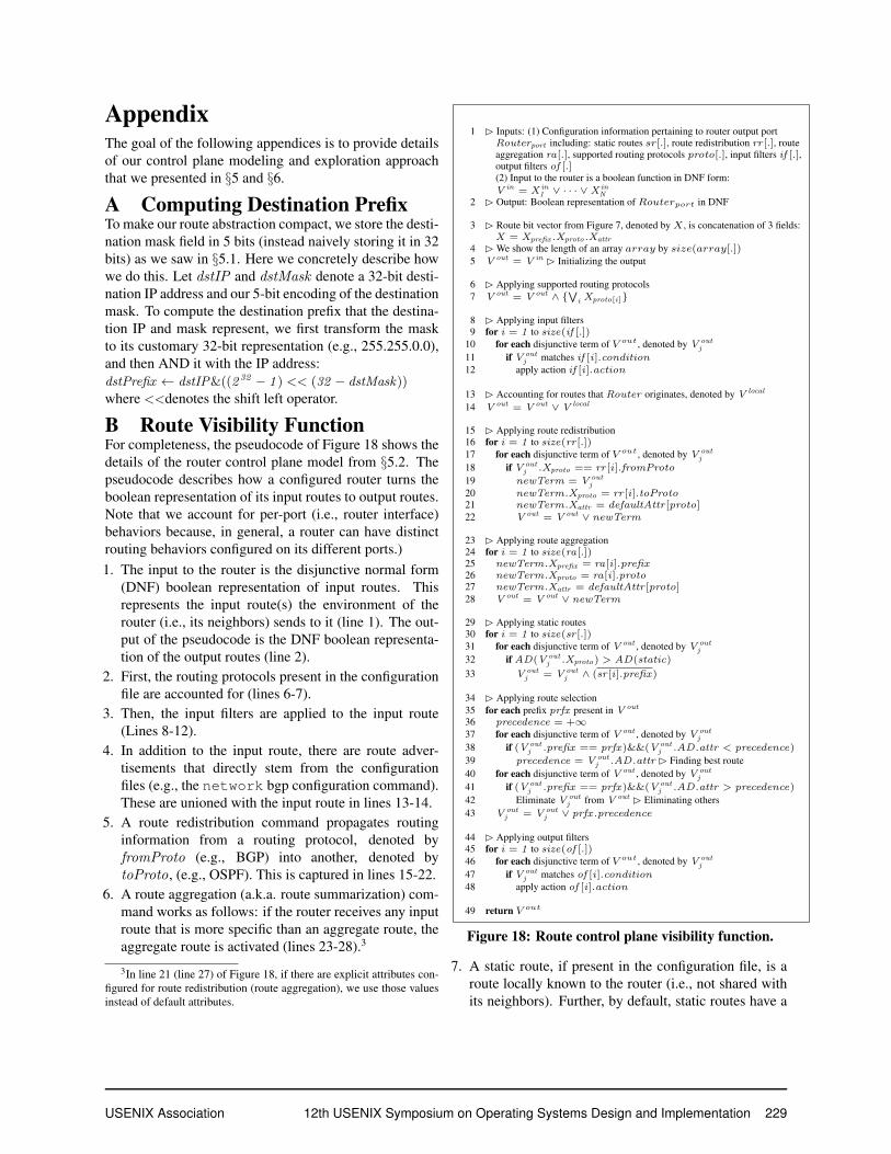
B Route Visibility FunctionFor completeness, the pseudocode of Figure 18 shows thedetails of the router control plane model from §5.2. Thepseudocode describes how a configured router turns theboolean representation of its input routes to output routes.Note that we account for per-port (i.e., router interface)behaviors because, in general, a router can have distinctrouting behaviors configured on its different ports.)1. The input to the router is the disjunctive normal form
(DNF) boolean representation of input routes. Thisrepresents the input route(s) the environment of therouter (i.e., its neighbors) sends to it (line 1). The out-put of the pseudocode is the DNF boolean representa-tion of the output routes (line 2).
2. First, the routing protocols present in the configurationfile are accounted for (lines 6-7).
3. Then, the input filters are applied to the input route(Lines 8-12).
4. In addition to the input route, there are route adver-tisements that directly stem from the configurationfiles (e.g., the network bgp configuration command).These are unioned with the input route in lines 13-14.
5. A route redistribution command propagates routinginformation from a routing protocol, denoted byfromProto (e.g., BGP) into another, denoted bytoProto, (e.g., OSPF). This is captured in lines 15-22.
6. A route aggregation (a.k.a. route summarization) com-mand works as follows: if the router receives any inputroute that is more specific than an aggregate route, theaggregate route is activated (lines 23-28).3
3In line 21 (line 27) of Figure 18, if there are explicit attributes con-figured for route redistribution (route aggregation), we use those valuesinstead of default attributes.
1 � Inputs: (1) Configuration information pertaining to router output portRouterport including: static routes sr[.], route redistribution rr [.], routeaggregation ra[.], supported routing protocols proto[.], input filters if [.],output filters of [.](2) Input to the router is a boolean function in DNF form:V in = X in
1 ∨ · · · ∨X inN
2 � Output: Boolean representation of Routerport in DNF
3 � Route bit vector from Figure 7, denoted by X , is concatenation of 3 fields:X = Xprefix .Xproto .Xattr
4 � We show the length of an array array by size(array[.])5 V out = V in � Initializing the output
6 � Applying supported routing protocols7 V out = V out ∧ {
∨i Xproto[i]}
8 � Applying input filters9 for i = 1 to size(if [.])
10 for each disjunctive term of V out, denoted by V outj
11 if V outj matches if [i].condition
12 apply action if [i].action
13 � Accounting for routes that Router originates, denoted by V local
14 V out = V out ∨ V local
15 � Applying route redistribution16 for i = 1 to size(rr [.])17 for each disjunctive term of V out, denoted by V out
j
18 if V outj .Xproto == rr [i].fromProto
19 newTerm = V outj
20 newTerm.Xproto = rr [i].toProto21 newTerm.Xattr = defaultAttr [proto]22 V out = V out ∨ newTerm
23 � Applying route aggregation24 for i = 1 to size(ra[.])25 newTerm.Xprefix = ra[i].prefix26 newTerm.Xproto = ra[i].proto27 newTerm.Xattr = defaultAttr [proto]28 V out = V out ∨ newTerm
29 � Applying static routes30 for i = 1 to size(sr [.])31 for each disjunctive term of V out , denoted by V out
j
32 if AD(V outj .Xproto) > AD(static)
33 V outj = V out
j ∧ (sr [i].prefix)
34 � Applying route selection35 for each prefix prfx present in V out
36 precedence = +∞37 for each disjunctive term of V out , denoted by V out
j
38 if (V outj .prefix == prfx)&&(V out
j .AD.attr < precedence)
39 precedence = V outj .AD.attr � Finding best route
40 for each disjunctive term of V out , denoted by V outj
41 if (V outj .prefix == prfx)&&(V out
j .AD.attr > precedence)
42 Eliminate V outj from V out � Eliminating others
43 V outj = V out
j ∨ prfx .precedence
44 � Applying output filters45 for i = 1 to size(of [.])46 for each disjunctive term of V out, denoted by V out
j
47 if V outj matches of [i].condition
48 apply action of [i].action
49 return V out
Figure 18: Route control plane visibility function.
7. A static route, if present in the configuration file, is aroute locally known to the router (i.e., not shared withits neighbors). Further, by default, static routes have a
USENIX Association 12th USENIX Symposium on Operating Systems Design and Implementation 229

1 � Inputs: (1) router-level topology of network(2) Set of router ports facing environment Env(3) routers configurations
2 � Output: Prefix(es) of traffic reaching from router port A to routerport B
3 Parse router configurations into boolean functions (using Figure 18)4 Initialize assumede on port e (by default, true)5 initialize assumedB on port B (by default, true)
6 � Accounting for effect of environment on routers on an A-to-Bpath
7 for each router routeri on an A− to − B path8 for each environment-facing port e ∈ Env9 for each path p from port e to routeri
10 � routerj is the jth router on e i,where 1 ≤ j ≤ M (j )
11 E ine→i,p = E in
e→i,p ∨ TM(j)(. . . (T1 (assumede)) . . . )
12 E ine→i = E in
e→i ∨ V ine→i,p
13 E ini = E in
i ∨ E ine→i
14 � Compute per-path reachability15 Find all paths from B to A in G:
PathB A = {path1B A, . . . , pathN
B A}16 � routerji is the jth router on pathi
B A,where 1 ≤ j ≤ M (j )
17 reachabilitypathi
B AB A =
TM(j)(. . . (T2 (Ein2 ∨ (T1 (E
in1 ∨ assumedB ))))
18 Eliminate binary variables in reachabilityA B except thosecorresponding to Xprefix
19 � Accounting for static routes20 staticA B =
∨i(∧k
(StaticPrefixRouterk
i))
21 reachabilityA B = reachabilityA B ∨ staticA B
22 � Accounting for on-path ACLs. Routerki is the kth router onpathi
A B
23 reachabilitypathi
B AB A =
reachabilitypathi
B AB A ∧ (
∨k
ACLsRouterk
i)
24 � Compute all paths reachability
25 reachabilityA B =∨i
reachabilitypathi
B AA B
26 return reachabilityA B
Figure 19: Computing A-to-B reachability.
lower AD value than dynamic routing protocols (e.g.,OSPF, BGP, RIP, IS-IS), which makes them take prece-dence over these protocols. These behaviors are cap-tures in lines 29-33.
8. Route selection is in charge of selecting the best routeout of multiple routes to the same destination prefix: (i)if the routes belong to different routing protocols, therouting protocol with the lowest AD value is selected,(ii) if the routes belong to the same routing protocol,the protocol-specific attributes determine which one isselected. We have encoded protocol-specific attributesin such a way that a smaller value denotes a more pre-ferred route. Route selection is shown in lines 34-43.
9. As lines 44-48 denote, the last operation of the router
is applying the output filters.
C Computing Traffic Reachablefrom A to B
We saw the high-level procedure to compute the trafficreachable from port A to port B in the network in §6.1.For concreteness, here we present the pseudocode for do-ing so (Figure 19).1. First, we account for the effect of the environment on
the routers that are located on a path from A to B(lines 6-13).
2. The pseudocode then computes the routes that canreach fromB toA over all paths between the two ports.For each path, we sequentially use the visibility func-tions of the on-path routers (lines 16-17). At this point,we have computed all route advertisement prefixes thatreach from B to A, which is the traffic prefixes thatreach from A to B.
3. Then, since we are interested in route prefixes reach-able from B to A, we ignore route fields that do notcorrespond to prefix (i.e., AD and attributes) in line 18.
4. In addition to these prefixes, there is potentially othertraffic that can reach from A to B to static routes con-figured on on-path routers. This is because while arouter does not advertise its static routes, proper staticroutes end up in its forwarding table. By a proper staticroute we mean a static route that points to the next on-path router as its next hop. We account for static routesin lines 19-20.
5. Since routers ACL rules restrict what traffic prefixeswill actually be forwarded, we then account for themin lines 22-23.Finally, the computed per-path reachability results are
unioned (lines 24-25).
230 12th USENIX Symposium on Operating Systems Design and Implementation USENIX Association

References[1] ERA. https://github.com/Network-
verification/ERA.
[2] 7007 Explanation and Apology. http://bit.ly/1e4djtW.
[3] BGP Message Generation and Transport, andGeneral Message Format. http://bit.ly/1VMOI0R.
[4] Border Gateway Protocol Path Selection. http://bit.ly/1T1w7IH.
[5] Cisco—What Is Administrative Distance? http://bit.ly/1OkgevM.
[6] Finding and Diagnosing BGP Route Leaks.https://blog.thousandeyes.com/finding-and-diagnosing-bgp-route-leaks/.
[7] JDD, a pure Java BDD and Z-BDD library.https://bitbucket.org/vahidi/jdd/wiki/Home.
[8] Juniper—Route Preferences. http://juni.pr/1fQC4LY.
[9] OSPF Message Formats. http://bit.ly/1TvOwwL.
[10] Purdue campus network configuration files.https://engineering.purdue.edu/
˜isl/network-config/.
[11] Route Leak Causes Amazon and AWS Out-age. https://blog.thousandeyes.com/route-leak-causes-amazon-and-aws-outage/.
[12] Stanford campus network configuration files.http://bit.ly/1rvoK5h.
[13] The Intel Intrinsics Guide. http://intel.ly/24sk3uz.
[14] The Internet Topology Zoo. http://www.topology-zoo.org/dataset.html.
[15] High Performance Service Chaining for AdvancedSoftware-Defined Networking (SDN) . http://intel.ly/1ilX5PG, 2014.
[16] R. Beckett, R. Mahajan, T. Millstein, J. Padhye, andD. Walker. Don’t mind the gap: Bridging network-wide objectives and device-level configurations. InProc. SIGCOMM, 2016.
[17] R. E. Bryant. Graph-based algorithms for booleanfunction manipulation. IEEE Trans. Comput.,35(8):677–691, 1986.
[18] N. Feamster and H. Balakrishnan. Detecting BGPconfiguration faults with static analysis. In Proc.NSDI, 2005.
[19] A. Fogel, S. Fung, L. Pedrosa, M. Walraed-Sullivan,R. Govindan, R. Mahajan, and T. Millstein. A gen-eral approach to network configuration analysis. InProc. NSDI, 2015.
[20] L. Gao. On inferring autonomous system relation-ships in the internet. IEEE/ACM Trans. Netw., 9(6),Dec. 2001.
[21] A. Gember-Jacobson, R. Viswanathan, A. Akella,and R. Mahajan. Fast control plane analysis using anabstract representation. In Proc. SIGCOMM, 2016.
[22] A. Gember-Jacobson, W. Wu, X. Li, A. Akella, andR. Mahajan. Management plane analytics. In Proc.IMC, 2015.
[23] T. G. Griffin, F. B. Shepherd, and G. Wilfong.The stable paths problem and interdomain routing.IEEE/ACM Trans. Netw., 10(2):232–243, Apr. 2002.
[24] T. G. Griffin and J. L. Sobrinho. Metarouting. InProc. SIGCOMM, 2005.
[25] T. G. Griffin and G. Wilfong. An analysis of BGPconvergence properties. In Proc. SIGCOMM, 1999.
[26] C. Guo, L. Yuan, D. Xiang, Y. Dang, R. Huang,D. Maltz, Z. Liu, V. Wang, B. Pang, H. Chen, Z.-W. Lin, and V. Kurien. Pingmesh: A large-scalesystem for data center network latency measurementand analysis. In Proc. SIGCOMM, 2016.
[27] F. J. Hill and G. R. Peterson. Introduction to Switch-ing Theory and Logical Design. 1981.
[28] P. Kazemian, G. Varghese, and N. McKeown.Header space analysis: static checking for networks.In Proc. NSDI, 2012.
[29] A. Khurshid, W. Zhou, M. Caesar, and P. B. Godfrey.Veriflow: verifying network-wide invariants in realtime. In Proc. NSDI, 2013.
USENIX Association 12th USENIX Symposium on Operating Systems Design and Implementation 231
[30] D. Knuth. The Art of Computer Programming, Vol-ume 4A: Combinatorial Algorithms, Part 1. 2011.
[31] F. Le, G. G. Xie, D. Pei, J. Wang, and H. Zhang.Shedding light on the glue logic of the internet rout-ing architecture. In Proc. SIGCOMM, 2008.
[32] F. Le, G. G. Xie, and H. Zhang. Instability freerouting: beyond one protocol instance. In Proc.CoNEXT, 2008.
[33] F. Le, G. G. Xie, and H. Zhang. Theory and newprimitives for safely connecting routing protocol in-stances. In Proc. SIGCOMM, 2010.
[34] F. Le, G. G. Xie, and H. Zhang. On route aggrega-tion. In Proc. CoNEXT, 2011.
[35] W. Liu, H. Li, O. Huang, M. Boucadair, N. Ley-mann, Z. Cao, and J. Hu. Service Function Chaining(SFC) Use Cases. http://bit.ly/1JTVneh,2014.
[36] N. P. Lopes, N. Bjørner, P. Godefroid, K. Jayaraman,and G. Varghese. Checking beliefs in dynamic net-works. In Proc. NSDI, 2015.
[37] H. Mai, A. Khurshid, R. Agarwal, M. Caesar, P. B.Godfrey, and S. T. King. Debugging the data planewith Anteater. In Proc. SIGCOMM, 2011.
[38] D. A. Maltz, G. Xie, J. Zhan, H. Zhang,G. Hjalmtysson, and A. Greenberg. Routing designin operational networks: A look from the inside. InProc. SIGCOMM, 2004.
[39] G. Varghese. Technical perspective: Treating net-works like programs. Commun. ACM, 58(11):112–112, Oct. 2015.
[40] S. Vissicchio, O. Tilmans, L. Vanbever, and J. Rex-ford. Central control over distributed routing. InProc. SIGCOMM, 2015.
[41] K. Weitz, D. Woos, E. Torlak, M. D. Ernst, A. Kr-ishnamurthy, and Z. Tatlock. Bagpipe: Verified BGPconfiguration checking. In Proc. OOPSLA, 2016.
[42] H. Yang and S. S. Lam. Real-time verification ofnetwork properties using atomic predicates. In IEEETransactions on Networking, 2015.
[43] H. Zeng, P. Kazemian, G. Varghese, and N. McK-eown. Automatic test packet generation. In Proc.CoNEXT, 2012.
232 12th USENIX Symposium on Operating Systems Design and Implementation USENIX Association