efficiency of excitation of piezoceramic transducer at
TRANSCRIPT

Efficiency of excitation of piezoceramic transducer
at antiresonance frequency
Mezheritsky A.V., “Efficiency of excitation of piezoceramic transducer at antiresonance frequency”,
adapted from IEEE Trans. Ultrason., Ferroelect., Freq. Contr., vol. 49, N 4, pp. 484-494, 2002.
Abstract. The efficiency of piezoceramic transducers excited at both the resonance and
antiresonance frequenc ies was investigated. Losses in piezoceramics are phenomenologically
considered to have three coupled mechanisms: dielectric, mechanical, and piezoelectric losses.
Expressions for the resonance and antiresonance quality factors, which ultimately determine the
transducer efficiency, have been received on the basis of complex material constants for both
stiffened and unstiffened vibration modes. Comparisons of electric and mechanical fields, thermal
and electrical losses of power supply, and their distribution in the transducer volume have then been
made. For a given constant mechanical displacement of the transducer top, the required electric
voltage applied to the transducer at the antiresonance frequency is proportional to the resonance
quality factor, while the changes in the intrinsic electric and mechanical fields characteristics in the
common case are not too essential. The requirements on the piezoceramic parameters, types of
transducer vibration, and especially on the factor of piezoelectric losses in a range of physically valid
values were established to provide maximal quality factors at the antiresonance frequency.
Author: A.V. Mezheritsky e-mail: [email protected] ( CC: [email protected] )

I. INTRODUCTION.
Piezoceramic materials (PCM) of a PZT system [1] have unique electro-elastic properties.
Piezoceramic transducers (PT) are used in electronics and hydro- and electroacoustics for a wide
range of applications. High power mechanical output PT characteristics are traditionally achieved at
the resonance frequency because of the relatively low requirement for electric voltage. However,
the process of PT heating and, as a consequence, failure of output PT characteristics in strong
electric and mechanical fields, restricts powerful PT applications. It requires optimization of regimes
of PT excitation. As predicted in [2], the advantages of excitation of the resonant powerful PT at an
antiresonance frequency, against the traditional resonant regime, with regard to PT heating and
power supply losses, have found experimental and practical confirmations [3] - [6]. Conclusive
specific and decisive roles of piezoelectric energy losses were determined.
The difference between the antiresonance fa and resonance fr PT frequencies [1], [8] depends
on a degree of PCM polarization, namely on the value of the coefficient of electromechanical
coupling (CEMC) kij and harmonic number n of a used type of vibration. The quality factor Q
characterizes resonant PT behavior. PZT-based PCM provide strong coupling of mechanical and
electric fields (CEMC value can reach 0.9, close to theoretical limit [7]), so the mechanical and
electrical components of energy losses, as well as the piezoelectric component describing losses at
interconversion of the mechanical and electrical energies, should be involved in the
phenomenological description of PT behavior. Traditionally, the resonance quality factor at the
fundamental (lowest) harmonic of a PT planar mode (disk) [1], [8] was chosen for characterizing
PCM quality.
Electro-elastic PT behavior caused by anisotropy of polarized piezoceramics generally is
described by ten independent constants [8], [9]. Because it is an electro-mechanical oscillatory
system, PT has two limit regimes of operation: short-circuit (s.c.) and open-circuit (o.c.) at closed
and broken PT electrodes, respectively. The CEMC value is determined by a difference between real
parts of the elastic PCM constants under a constant [1] electric field strength E and induction D,
corresponding in common case to the s.c. and o.c. regimes, in particular, 233 33 33(1 )D ES S k= − , where
k33 is the CEMC as 2 233 33 33 33
E Tk d S ε= . The CEMC as a real value defines a share of the total energy
accumulated in PT and converted from mechanical into electrical forms and vice versa. In turn, the
values of the quality factors corresponding to the s.c. (Qs.c.) and o.c. (Qo.c.) regimes in common case
are defined by the complex elastic constants (e.g., ES33ˆ and DS33
ˆ ), whose imaginary parts are defined
by the mechanical, dielectric, and piezoelectric mechanisms of energy losses [9]. Taking into

account the piezoelectric component of losses for consideration was offered for the first time in [10];
the presence of a non-zero imaginary part of the piezocoefficient was found by direct measurement
[11]; a high accuracy method of complex material constant determination was proposed in [12];
the physically valid limits on the piezoelectric loss factors was established in [9] according to the
condition of “positivity” of local thermal losses in a piezoelectric media; the concept of complex
material constants was used in [13], [14] to model dynamic PT response. Involving domain
mechanism of energy loss [15] with damped (time delay) movement of walls of 90-degree domains,
the uniform physical nature of coupled mechanical, dielectric, and piezoelectric energy loss
components was shown.
In the common case, there are two basic types of PT vibrations: stiffened mode (SM) with
direction of vibration along an exciting electric field (e.g., rod 15x2x2 mm PT (Fig. 3)) when the
electric field induction is homogenous between electrodes [8], and unstiffened mode (UM) with
direction of vibration perpendicular to the vector of an exciting electric field (e.g., bar 15x1x0.5 mm
PT (Fig. 7)) when the electric field strength is homogenous between electrodes in the case of thin PT
plate. Ultimately, research regarding the interrelation of the PT dissipative characteristics at the
resonance and antiresonance frequencies – the resonance Qr and antiresonance Qa quality factors –
is of practical and theoretical interest.
II. COMPLEX ELASTIC COMPLIANCES QUALITY FACTORS .
The electromechanical behavior of a real PT with energy losses generally is described [9] by:
the complex constants of the PCM material matrix
, , ,ˆ (1 )E D E D E Dij ij ijS S i Q≡ − , ˆ (1 )kl kl kld d iγ≡ − , ˆ (1 )T T
mn mn mniε ε δ≡ − ; ( 1 )
the linear equations of piezoeffect si = EijS Tj + ˆ
kid Ek , Dn = Tmnε Em + ˆ
nld Tl ;
and the equation of motion ρ utt’’=∇T at a given boundary and initial conditions,
where 1−≡i , QijE,D are the quality factors of the complex elastic compliances DE
ijS ,ˆ ,
δmn and γki are the dielectric and piezoelectric loss angles, respectively, ρ is the PCM density,
D and E, s and T are the electric field induction and strength, mechanical strain and stress,
respectively, in a vector or tensor performance, ∇ is the vector operator, u is the local mechanical
displacement. Similar performance is used for the constants of the material matrixes through
STmnklklkl
DEij hegC ,, ˆ,ˆ,ˆ,ˆ,ˆ β [8], [9].

Particularly, the complex constants DES ,33
ˆ with their interrelation 233 33 33
ˆˆ ˆ (1 )D ES S k= − , where 33k is
the complex CEMC, have “elastic constant quality factors” determined by the base relation:
( )
−+−
−=
−−
−−= 3333
2333
2
33332332
33333333332
33
233
3333
)1(21)1(
1121
11 δδδγ EEEEED
QktQkkQQk
kQQ
. ( 2 )
From the condition of “positivity” of the local thermal energy losses, the limitation on the value
of the piezoelectric loss angle was phenomenologically established [9] as follows
|γ33 | ≤ y3 ≡ 2
33 33 33Ek Qδ , or t3 ≡ γ33 / y3 ∈ [-1; 1] . ( 3 )
Under that condition, the “thermal local dissipation” is always positive, that means heating, so
integral dissipation for the whole transducer is positive too, consequently. Meanwhile, it does not
mean that each of the components causing the thermal losses, such as local losses of the electric or
mechanical fields, must be positive separately in a piezoelectric body, especially with strong
coupling of the electric and mechanical fields.
According to (2), 33DQ can be generally greater or less than 33
EQ . The maximum increase of the
33 33D EQ Q is provided by the non-zero imaginary part γ33 of the piezocoefficient and corresponds to
the conditions 233 33 33
Ek Q δ → 1 and t3 → 1. In a specific case of absence of the dielectric
(δ33 = 0) and piezoelectric (γ33 = 0) losses: 233 33 33 33(1 ) (1 2 )D E E
rQ Q k Q δ= − ≅ − , where influence of the
relative frequency resonant interval δr has opposite sign and stronger effect in comparison to the
traditional PT equivalent circuit (EC), taking into account, as it is considered, only the mechanical
losses [1] (see chapter VI).
Further, the following definition of the quality factor of a PT resonance (resonant peak) and
accordingly a method for its calculation are used. Taking the expression describing the resonant PT
behavior, after decomposition it by the small dissipative parameters ( ,1 E DijQ , δmn , γkl ) and relative
frequency displacement 0 1f fχ = − from the "ideal" frequency f0 of the resonant peak (loss-free),
this expression is performed [21] by first-order approximation as 1
BiA
iξ+
+,
where A, B are coefficients, and the quality factor Q of the resonant peak is defined as a coefficient
in the generalized frequency displacement 2 Qξ χ= . The given approach methodically
corresponds in full measure to the known frequency methods [1], [8] of quality factor determination,
which are based on the measurement of characteristic frequencies of the real and imaginary parts of

resonant PT characteristics (e.g., admittance or impedance), and related to them methods [3], [4],
[16], [17].
III. PT with STIFFENED VIBRATION MODE.
A. Resonance and Antiresonance PT Quality Factors
Let's further consider a “long rod” PT representing the SM vibration. The given type of
longitudinal PT vibration along the vector of polarization is generally described by the complex
electro-elastic PCM constants [1], [8], [9]: DES ,33
ˆ (quality factors ,33E DQ ), T
33ε (δ33) , 33d (γ33).
The PT complex impedance is the following
2332
0 33
1 tan( /2)ˆ1ˆˆ / 2(1 )Kh
Z kKhi C kω
= − − /
, ( 4 )
where 0C ( T33ε ) , 2K = ω2 ρ DS33
ˆ , 233k = 2
33d / T33ε ES33
ˆ are the quasistatic PT capacitance and the
expressions for the complex wavenumber and CEMC, respectively, h is the PT length.
Using (4), after decomposition of the expressions for the PT admittance (1/Z) and impedance (Z)
by the small parameters of the relative frequency displacement and dissipative coefficients in a
vicinity accordingly of the resonance , 332 Er n nf B h Sρ= and antiresonance , 332 D
a nf n h Sρ=
frequencies [21], where 23312 kqB nn −= π , qn is the nth-root of the frequency equation
233tan kqq = ( e.g., B1 – 1 = 0.024 at k33 = 0.5 ), we will receive in common case the expressions
for the resonance Qr,n and antiresonance Qa,n quality factors of n-harmonic:
−−
−−=
EinnEnr Qk
kH
QQ 33,33332
33
233
33,
12
111
δγ ( ) 22 2 233 33 3 33 33 33 33 ,2
33 33
11 1 2(1 )
1E E En
n D D E i nE
HH k Q t k Q k Q
Q kδ δ δ
= − + − + − + − , (5)
−−
−−=≡ EED
na Qkk
QQQ 3333332
33
233
3333,
12
1111
δγ ( ) 22 2 233 33 3 33 33 33 33 , ,2
33 33
1 1 2(1 ) ( )(1 )
E E ED D E i n EoutE
k Q t k Q k QQ k
δ δ δ δ = − + − + + − , (6)
where )(
)1(21 4
33233
2
233
kkqk
Hn
n +−−
−= . Note that the coefficient Hn( k33 ) has values (at k33 = 0…0.7) :
H1 = 0.18…0.10, H3 = 0.91…0.95, H5 = 0.97…0.98, and further, nH →∞ → 1.
For the fundamental harmonic (n = 1) we will further use the following approximation (no more
10%) for the coefficient 2433
233
21
233 8)1(2
π≅
+−−
kkqk
, so that 18.0/81 21 ≈−≅ πH . Thus, the resonance
and antiresonance PT resistances are:

1 20 332
8r r rR C k Qω
π− ≅ ,
233
2 20 33
8(1 )
aa
a
k QR
C kπ ω=
− . ( 7 )
Here δ33 = δD + δE (δE = δE,in + δE, out ), δ33,in = δD + δE,in , |γ33 | ≤ y3 ≡ E
D Qk 33233δ ,
t3 = γ33 / y3 ∈ [-1; 1], δD is the dielectric (domain) component of the dielectric loss angle, δE is the
component caused by the conductivity of free charges (internal δE,in and external δE, out ;
the last one can be PT surface conductivity or a resistor connected in parallel to PT).
In accordance with (5) and (6) for the fundamental harmonic (n = 1) of our interest, the resonance
quality factor Qr ≅ 33EQ (taking into account H1 << 1) and Qr has weak dependence on the other
dissipative PCM parameters. At the same time, the range of variation of the antiresonance quality
factor Qa value can reach in common case some orders, that depends on a combination of the
dissipative PCM parameters. The thermal (irreversible) PT energy losses )/1(Re5.02
ZVW =
under an electric excitation by the voltage V are determined by the real part of the PT complex
admittance. Re(1/Z) is the most sensitive to the piezoelectric loss component ( t-parameter) at the
frequencies above the resonance, including near-antiresonance frequency range (Fig. 1).
Figure 1. Calculated frequency
dependence of the real part of the rod PT
admittance for different values of
t(3) – parameter and 33EQ =100, k 33 = 0.7,
and δ33 = 0.015.
Calculated according to (4), the frequency dependence of the real part of the rod PT admittance at
the fundamental harmonic is given in Fig. 1, which illustrates described PT dissipative properties at
variation of the piezoelectric loss value in the presence of dielectric loss. The frequency dependence
of the dissipation has a minimum (Fig. 2), which frequency matches the antiresonance at
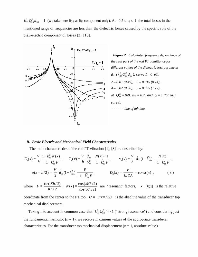
233 33 33
Ek Q δ ≅ 1 (we take here δ33 as δD component only). At 0.5 ≤ t3 ≤ 1 the total losses in the
mentioned range of frequencies are less than the dielectric losses caused by the specific role of the
piezoelectric component of losses [2], [18].
Figure 2. Calculated frequency dependence of
the real part of the rod PT admittance for
different values of the dielectric loss parameter
δ33 ( 233 33 33
Ek Q δ ): curve 1 – 0 (0),
2 – 0.01 (0.49), 3 – 0.015 (0.74),
4 – 0.02 (0.98), 5 – 0.035 (1.72),
at 33EQ =100, k33 = 0.7, and t3 = 1 (for each
curve).
- - - - - line of minima.
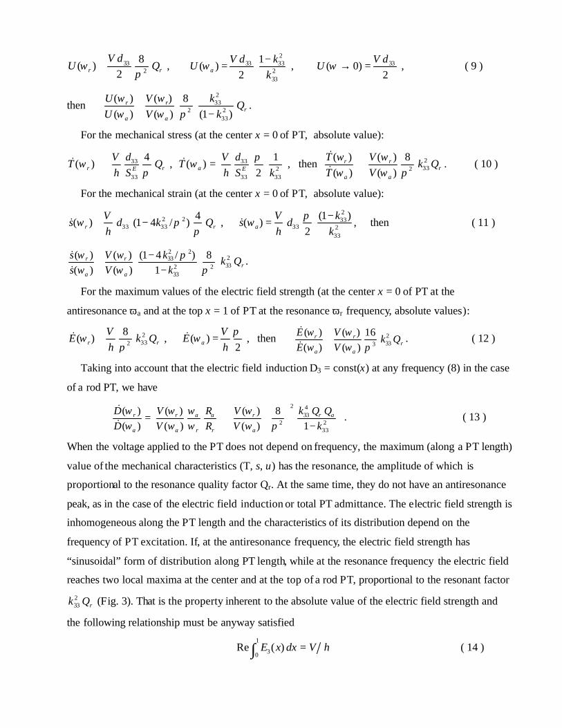
B. Basic Electric and Mechanical Field Characteristics
The main characteristics of the rod PT vibration [1], [8] are described by: 233
3 233
ˆ1 ( )( ) ˆ1
k N xVE x
h k F
−=
− + , 33
3 233 33
ˆ ( ) 1( ) ˆ ˆ1E
dV N xT x
h S k F
−=
− + , 2
3 33 33 233
( )ˆ ˆ( ) (1 ) ˆ1
V N xs x d k
h k F= −
− + ,
233 33 2
33
ˆ ˆ( /2) (1 ) ˆ2 1
V Fu x h d k
k F= = −
− + , 3( ) ( )
VD x const x
i Zω= =
∆ , ( 8 )
where2/
)2/tan(Kh
KhF ≡ ,
cos( /2)( )
cos( /2)xKh
N xKh
≡ are “resonant” factors, ]1;0[∈x is the relative
coordinate from the center to the PT top, U ≡u(x=h/2) is the absolute value of the transducer top
mechanical displacement.
Taking into account in common case that 233 33
Ek Q >> 1 (“strong resonance”) and considering just
the fundamental harmonic (n = 1), we receive maximum values of the appropriate transducer
characteristics. For the transducer top mechanical displacement (x = 1, absolute value) :
332
8( )
2r r
V dU Qω
π≅ ,
233 33
233
1( )
2aV d k
Uk
ω−
= , 33( 0)2
V dU ω → = , ( 9 )
then 233
2 233
( ) ( ) 8( ) ( ) (1 )
r rr
a a
kU VQ
U V kω ωω ω π
≅−
.
For the mechanical stress (at the center x = 0 of PT, absolute value):
33
33
4( )r rE
dVT Q
h Sω
π≅& , 33
233 33
1( )
2a E
dVT
h S kπ
ω =& , then 2332
( ) ( ) 8( ) ( )
r rr
a a
T Vk Q
T Vω ωω ω π
≅&& . ( 10 )
For the mechanical strain (at the center x = 0 of PT, absolute value):
2 233 33
4( ) (1 4 / )r r
Vs d k Q
hω π
π≅ −& ,
233
33 233
(1 )( )
2akV
s dh k
πω
−=& , then ( 11 )
2 2233332 2
33
(1 4 / )( ) ( ) 8( ) ( ) 1
r rr
a a
ks V k Qs V k
πω ωω ω π
−≅−
&& .
For the maximum values of the electric field strength (at the center x = 0 of PT at the
antiresonance ωa and at the top x = 1 of PT at the resonance ωr frequency, absolute values):
2332
8( )r r
VE k Q
hω
π≅& , ( )
2a
VE
hπ
ω =& , then 2333
( ) ( ) 16( ) ( )
r rr
a a
E Vk Q
E Vω ωω ω π
≅&& . ( 12 )
Taking into account that the electric field induction D3 = const(x) at any frequency (8) in the case
of a rod PT, we have
2 4
332 2
33
( ) ( ) ( ) 8( ) ( ) ( ) 1
a a r ar r r
a a r r a
R k Q QD V VD V R V k
ωω ω ωω ω ω ω π
= ≅ −
&& . ( 13 )
When the voltage applied to the PT does not depend on frequency, the maximum (along a PT length)
value of the mechanical characteristics (T, s, u) has the resonance, the amplitude of which is
proportional to the resonance quality factor Qr. At the same time, they do not have an antiresonance
peak, as in the case of the electric field induction or total PT admittance. The electric field strength is
inhomogeneous along the PT length and the characteristics of its distribution depend on the
frequency of PT excitation. If, at the antiresonance frequency, the electric field strength has
“sinusoidal” form of distribution along PT length, while at the resonance frequency the electric field
reaches two local maxima at the center and at the top of a rod PT, proportional to the resonant factor 233 rk Q (Fig. 3). That is the property inherent to the absolute value of the electric field strength and
the following relationship must be anyway satisfied
1
30Re ( )E x dx V h=∫ ( 14 )

Figure 3. Distribution of electric field (absolute
value) along length of a rod resonator at the
resonance (r) and antiresonance (a) frequencies
at equal PT top displacement.
33EQ =100, k33 = 0.7, δ33 = 0.015, and t3 = 1.
For the energy loss efficiency under the same conditions, taking into account a common expression
for the active energy losses of a generator of transducer excitation 2
0.5 Re(1/ )W V Z= , we have :
22 2
0 332
1 8( )
2 2r r rr
VW V C k Q
Rω ω
π= ≅ ,
22 22 33
0 233
11( )
2 2 8a aa a
kVW V C
R k Qπ
ω ω−
= = , ( 15 )
then 2 2 4
332 2
33
( ) ( ) 8( ) ( ) 1
r ar r r
a a a
k Q QW VW V k
ω ω ωω ω ω π
≅ − .
If we consider the condition U(ωr)= U(ωa) (denoted by a vertical line) of our interest, then
2
233332 2
33
( ) 8(1...2)
( ) (1 )a
r rr
V kQ k Q
V kωω π
≅ ≈−
( 16 )
(the last estimation is given for the range of k33 = 0…0.7). For the other characteristics we have
233
( ) 11...2
( ) 1a
r
TT k
ωω
≅ ≈−
&& , 2 2
33
( ) 11...1.25
( ) 1 4a
r
ss k
ωω π
≅ ≈−
&& , ( 17 )
233
( ) 11.5...3
( ) 2 1a
r
EE k
ω πω
≅ ≈−
&& ,
2
233
( ) 1( ) 8
a
r a
DD k Q
ω πω
≅&& , ( 18 )
233
( ) 1(1 )
( ) (1...2.5)a ar r
a r a r
Q QWk
W Q Qω ωω ω
≅ − ≈ . ( 19 )
So, to provide equal amplitude of the PT top mechanical displacement at both the antiresonance
and resonance frequencies, it is required that one applies a voltage to PT at ~ 2332 rk Q greater

(proportional to the resonance quality factor). At the same time, the maximum values (with respect
to PT volume) of the mechanical strain and stress are no more than 1.3 and 2 times greater,
respectively, at the antiresonance frequency, and these differences depend only on the CEMC value,
but not dissipative characteristics (quality factor, etc.). Note that even if the voltage applied to a rod
PT at the antiresonance frequency is too high (~ 2332 rk Q ≅ 100 at k33 = 0.7 and 33
EQ =100),
the maximum strength of the electric field (relative value) does not exceed 3 times and this ratio
does not depend on quality factors. For this reason, non- linear effects at a strong level of PT
excitation must be commensurable for the resonant and antiresonant regimes of PT excitation at
equal PT top mechanical displacement, that allows to extend presented results to the practically
important case of high power loading. At the same time, character of field distribution in the PT
volume can differ significantly. The piezoelectric loss factor causes changes not only in total PT
energy losses, but also influences the distribution of the thermal losses in the PT volume and can
provide specific PT regions with an extremely low or high heating (Fig. 4).
Figure 4. Distribution of thermal losses
along length of a rod PT at the resonance
and antiresonance frequencies at equal PT
top displacement for different values
(-1, 0, +1) of t(3) - parameter of
piezoelectric losses. 33EQ =100, k33 = 0.7,
δ33 = 0.015. There are no piezoelectric
losses at t3 = 0.
The parameter (19) of relative energy losses of the electric source of PT excitation (total thermal
losses in the whole PT volume), ultimately defining relative efficiency of PT excitation at the
antiresonance frequency, are proportional to the ratio of the antiresonance quality factor to the
resonance one with some coefficient depending only on the CEMC (relative resonant frequency
interval). The expression and value of this factor depends on initial task in respect to the regime of

PT excitation. We have considered here the characteristics of the same PT at the resonance and
antiresonance frequencies, whose relative difference depends only on the CEMC value and can
exceed about 25…40% (for k33 case). For this reason, the vibrational velocities have an additional
difference by the same factor at equal amplitude of PT top mechanical displacement at the respective
frequencies. For practical purposes, the comparison of two different PTs with equal resonance and
antiresonance frequencies, respectively, easily can be made on the basis of the given relationships.
Figure 5. Calculated dependence of total
loss energy efficiency for the resonance
and antiresonance frequencies on t(3) –
parameter at equal top displacement of a
rod PT. 33EQ = 100 and δ33 ( 2
33 33 33Ek Q δ ):
curve 1 – 0 (0), 2 – 0.01 (0.49),
3 – 0.015 (0.74), 4 – 0.02 (0.98),
5 – 0.035 (1.72), all at k 33 = 0.7,
6 – 0.044 (0.98) at k33 = 0.47,
7 – 0.083 (0.98) at k33 = 0.34.
Either way, for the total losses at the antiresonance frequency to be less than losses at the
resonance frequency, the ratio of the respective quality factors must be at least a rQ Q > 1.5…2,
and for higher efficiency should essentially exceed this value (Fig. 5).
Functional dependences of the resonance Qr and antiresonance Qa quality factors on the
mechanical, dielectric, and piezoelectric components of losses are described by (5) and (6). Taking
into account that, for the SM vibration, H1 << 1 at the fundamental mode (n = 1), we have Qr ≅ 33EQ
and Qa = 33DQ . From (5) and (6), follows that maximum values of the quality factors Qr and Qa
correspond to the conditions
1)(3333233 ≅D
EQk δ and 13 →t . ( 20 )
The resonance quality factor max Qr = 33 1(1 )EQ H− ≅ 233 8EQ π ≅ 331.25 EQ . Theoretically
max Qa is unlimited, and the difference between Qa and Qr can reach some orders in an ideal case.
When considered traditionally, only the mechanical and dielectric mechanisms of energy losses
causes a decrease (more than 2 times in respect to 33EQ ) in the antiresonance quality factor.

The possibility of an increase of the Qa quality factor value is a direct consequence of the presence
of the non-zero imaginary part (at t3 > 0) of the 33d piezocoefficient. An increase of the Qa quality
factor value is definitely impossible at 233 33 330.1 Ek Qδ <; and 2
33 33 333.5 Ek Qδ >; (Fig. 6).
Figure 6. Calculated
dependence Qa(r) / Q versus
2k Qδ according to (5, 6) and
(23, 24) using generalized
parameters for: k = 0.6,
Hn(Fn) = 1 (—), 0.8 (- - -), and
t = 1 (curve 1), 0.92 (2),
0.85 (3), 0.5 (4), 0 (5).
From the experimental data for a PZT-based PCM, it follows that the received values of
t3 = +0.5...0.95 correspond to a maximum degree of polarization. In common case, the parameter t3
is proportional to the CEMC k33 . According to the particular mechanism of energy losses [15], the
damped movement of walls of 90-degree domains provides the t3 - parameter, that is determined by
only an effective angle α0 ∈ (90…180)° of domain orientation as t3 = )1)(1()( 4231 AAAA −−− ,
where Am = sin(mα0)/mα0 . We can estimate the character of change of the piezoelectric loss angle
γ33 = 33 33ˆ ˆd d′′ ′ , depending on PCM polarization ( P ): 33d ′′ ~ sin3(α0) and 33d ′ ~ 1+ cos(α0). For P →0
it follows, that γ33 → 0 ( 33EQ and δ33 are supposed to be practically constant). However, the γ33
value varies within limits of 20 % in a wide interval (1…0.1) of a saturated polarization (max k33 ),
i.e. for the mentioned interval of the CEMC values, it is possible to accept that γ33 ≈ const ( P ), then
t3 = EQk 33333333 δγ ~ k33 . ( 21 )

IV. PT with UNSTIFFENED VIBRATION MODE.
A. Resonance and Antiresonance PT Quality Factors
Let's further consider a “long bar” PT representing the UM vibration. The given type of PT
vibration in a plane perpendicular to the vector of polarization is generally described by the complex
electroelastic PCM material constants [1], [8], [9]: DES ,11
ˆ (quality factors ,11E DQ ), T
33ε (δ33) , 31d (γ31).
The complex dynamic admittance of the bar PT is described by:
+−/=
2/)2/tan(ˆˆ1ˆ 2
312310 Kb
KbkkCiY ω , ( 22 )
where 0C ( T33ε ) , 2K = ω2 ρ ES11
ˆ , 231k = 2
31d / T33ε ES11
ˆ are the quasistatic PT capacitance and the
expressions for the complex wavenumber and CEMC, respectively, b is the PT length.
After decomposition the expressions for the PT admittance (Y) and impedance (1/Y) by the small
parameters of the relative frequency displacement and dissipative coefficients in a vicinity of
accordingly the resonance , 112 Er nf n b Sρ= and antiresonance , 112 D
a n nf G b Sρ= frequencies
[21], where π23112 kqG nn −= , qn is the nth-root of the frequency equation 2
31231)1(tan kkqq −−=
( e.g., 1– G1= 0.031 at k31 = 0.5), we will get the expressions for the resonance Qr,n and
antiresonance Qa,n quality factors (n = 1, 3, 5... - harmonic number):
, 11E
r nQ Q= , ( 23 )
−−
−−= EnE
na Qkk
FQQ 11
3331231
231
11,
12
111
δγ ( ) 22 2 231 11 1 31 11 31 112
11 31
11 1 2(1 )
1E E En
n D D EE
FF k Q t k Q k Q
Q kδ δ δ
= − + − + − + − , (24)
where 231
2 2 2 2 431 31
2(1 )(2 1)n
n n n
kFq q k q k
−=− − +
. Note that the coefficient Fn ≡ Fn( k31 ) has values:
1F = 8/π2 (≈0.81)…0.75 at k31 = 0…0.5 , and further, nF →∞ ~ 21 n . Here |γ31 | ≤ y1 ≡ E
D Qk 11231δ ,
t1 = γ31 / y1 ∈ [-1; 1]. For the fundamental harmonic (n = 1) the resonance Rr and antiresonance Ra
PT resistances are described by (7) with replacement of k33 → k31 parameters.
Thus, the resonance quality factor Qr value at the fundamental mode is determined exactly by the
quality factor 11EQ of the complex elastic compliance ES11
ˆ : Qr = 11EQ . Taking into account, that for
the UM vibration 1 1F ; (n = 1), we have Qa ≅ 11DQ . From (24), it follows, that maximum value of
the antiresonance quality factor Qa at the fundamental mode corresponds to the conditions

231 11 33( )
EDk Q δ = 1 and t1 = 1, thus max 11 1 11(1 ) 5.3E E
aQ Q F Q= − ≅ . Theoretically in an ideal case the
difference between Qa and Qr can be extremely appreciable.
B. Comparative Analysis of the Loss Distribution in a PT Volume for the
Stiffened and Unstiffened Modes of Vibration.
The resonance quality factor Qr (n = 1) of the UM vibration is only determined by the mechanical
loss component ( 11EQ for a bar PT), but, for the SM vibration, it depends on both 33
EQ (rod PT) and, to
some degree, the dielectric and piezoelectric loss components. The influence of the last components
takes place because, in the case of SM vibration, the local electric field E is inhomogeneous between
the PT electrodes and has resonant character (similarly to current, deformation, etc.) under the
condition (14). The local value of the field strength E at the resonance increases by orders that, as a
consequence, increases a share of the dielectric (and piezoelectric) loss component in the total
resonance energy loss. In particular, for this reason, the contribution of conductivity of free volume
charges into the value of the resonance quality factor increases (mainly in the PT volume regions
with large resonant values of the field E), but there is no contribution of surface or external
conductivity where field E has normal, non-resonant value. At the same time, in the case of UM
vibration, the electric field strength has relatively low value due to its non-resonant behavior.
Figure 7. Calculated distribution
of the local electrical losses along
length of a bar PT at the
resonance (r) and antiresonance
(a) frequencies under the
condition of a constant PT top
displacement (U) for: 11EQ = 100,
k31 = 0.7, δ33 = 0.02 and
t(1)-parameter in the allowed
range [-1, 1] (shown in
parentheses).

Relative properties of the mechanical field (strain, stress) in the case of bar PT (UM) are described
by the relationships similar to (17) for the rod PT case (SM). However, the distributions of the
electric field strength and induction differ essentially. The electric field strength E3 = const(f) does
not depend on frequency and has homogeneous distribution in bar PT volume. The electric field
induction has inhomogeneous distribution along bar PT length (frequency-specifying size), has also
resonant (max ~ 231 rk Q ) and antiresonant (min ~ 2
311 ak Q ) peaks, and provides specific volume
distribution of both local losses of electric source of excitation and local thermal losses (Fig. 7, 8).
The local losses of the electric field are described by ))(Im(5.0))(Re(5.0)( *33
*3 xDExjExp ω== ,
where j(x) is the current density (* - complex conjunction), then the total in PT volume Ω energy
loss of power supply is 2
( ) 0.5 Re(1/ )P p x d V ZΩ
= Ω =∫ and equals the total PT thermal loss. When
the value of t1-parameter of the piezoelectric loss lies in the interval t1 = 0.8…1, the energy losses
of the electric field in some frequency range, including the antiresonance frequency,
are negative at the center region of the bar PT (Fig. 7). It means that the current at the PT center is
opposite to the applied voltage, i.e. the local “negative dynamic conductivity” [2], [18] of the central
region of the bar PT takes place. At the same time, the local thermal dissipation is always positive at
any point of the PT volume (Fig. 8).
Figure 8. Calculated distribution
of local thermal losses along
length of a bar PT at the
resonance (r) and antiresonance
(a) frequencies under the
condition of a constant PT top
displacement (U) for: 11EQ =100,
k31= 0.7, δ33 = 0.02 and
t(1) - parameter in the allowed
range [-1, 1] (shown in
parentheses).
The reason of such difference in distribution of the local thermal and electric field losses depends
on redistribution (energy flux) of coupled electro-mechanical energy because of the concept of the
Umov-Pointing vector [19]. Particularly in the case of bar PT

)(Im5.0)()( *11 sTxwxp ω−= , ( 25 )
where w(x) is the local thermal loss. As PT is supposed to be electrically excited only, according to
the boundary conditions, the total in PT volume irreversible flux of the “mechanical” energy
1 *1 10
Im( ) 0x
xT s d
=
=Ω =∫ . Note that the function of distribution of the thermal losses at the
antiresonance frequency has two maxima at the center and top of the bar PT at positive values of
t1-parameter. The last feature is very important for a comparative experiment on the determination of
the efficiency of two regimes of PT excitation and must be taken into account. If a temperature
(heat) detector is located only at the PT center [3], the error in total energy heating measurement can
be double, and incorrect conclusion on the energy efficiency could be made.
The specific features of the considered bar PT behavior and the basic quality factors relationships
(23) and (24) are similar to a disk PT of radial (planar) vibration (UM). Taking into account that
CEMC kp >> k31 and that the t(p)-parameter of piezoelectric losses is proportional to CEMC,
described effects have to take place to a greater degree in the case of disk PT. Calculated according
to (23) and (24), the dependence a rQ Q (n = 1) versus 211 33E
ijk Q δ for various values of the
generalized F and t parameters is shown in Fig. 6, and is applied both to the bar and disk PT.
Commonly, the quality factors, such as Qr of the resonance PT peak, 11EQ of appropriate elastic
constant, and Qs.c. corresponding to the short-circuit regime, are approximately equal to each other at
least for the fundamental harmonic (the same property takes place for the set of the quality factors
Qa , 11DQ and Qo.c. at antiresonance). The difference between them inside each set depends on the
type of vibration, harmonic number, etc. They are exactly equal just for a PT with “concentrated
parameters”, such as thin ring resonator, when all local resonant mechanical and electrical
characteristics (deformation, strength, etc.) are homogeneous in the PT volume.
V. EXPERIMENTAL RESULTS on QUALITY FACTOR RELATIONSHIPS.
According to (23) and (24), the character of the difference between Qr and Qa is stipulated by the
piezoelectric dissipative effect caused by the non-zero imaginary part of the piezocoefficient, the
difference increases with CEMC growth. The experimental dependence of the disk PT quality
factors on a degree of polarization ( kp (δr) ) is shown in Fig. 9. The antiresonance Qa(δr) relationship
has the strongest dependence, which increases with growth of polarization. For the maximum
achieved kp = 0.55 (δr = 0.15), the ratio a rQ Q reaches more than 2, at kp→ 0 Qa → Qr → Q0 to

the quality factor of a non-polarized PCM. Meanwhile, the Qr(δr) curve reflects the known fact [1]
that Qr decreases insignificant ly as PCM polarization increases.
Figure 9. Influence of the relative resonant
interval δr of a disk PT with planar mode of
vibration on the resonance Qr ,
antiresonance Qa quality factors, and their
ratio a rQ Q :
lines 1, 2 - interpolation of the experimental
values of Qr (1) and Qa (2),
lines 3, 4 – calculated dependences
a rQ Q (δr) according to (24) at 0Q = 600,
δ33 = 0.007 and accordingly: 3 - max tp = 1
(at kp = 0.63), 4 - tp = 0 (γ31 = 0).
PCM PZT-35Y.
Calculated dependence a rQ Q for a planar mode of vibration in view of the conditions
γ31 = const (δp) and tp ~ kp (21) in the researched range of polarization has shown a satisfactory
agreement of theoretical and experimental data, and tp ≅ 0.90 was observed at maximum achieved
CEMC value. The absence of the imaginary part of the piezocoefficient ( γ31 , tp = 0 ) should have
resulted in the converse effect – decreasing of a rQ Q more than 2 times.
Rhombohedral, morphotropic and tetragonal [1] PCM compositions were involved into the
experimental research. For the disk PT with radial mode of vibration the maximum a rQ Q value
corresponds to the fundamental harmonic (n = 1), and the ratio a rQ Q (n = 1) reaches 1.8…2.4,
while the ratio a rQ Q (n = 1) can not exceed 3.0 for max F1 ≅ 0.8 and tp = 0.95 according to (24).
It is necessary to take into account, that the dielectric loss angle consists of two components
δ33 = δD + δE , defined accordingly by the domain mechanism of energy losses δD (which determines
tp ( t1, t3 ) value), and by the conductivity of free charges δE . The last component adds additional
term to the expressions (5), (6) and (24) resulting in decreasing of a rQ Q .

Figure 10. Experimental dependence of the
resonance Qr and antiresonance Qa planar
quality factors at the fundamental harmonic
of a disk PT on the factor of dielectric losses
tan δ(33) (1 kHz). PCM PZT-35Y.
The experimental data presented in Fig. 10 show the dependence of the resonance Qr and
antiresonance Qa planar quality factors at the fundamental mode of the disk PT on the factor of
dielectric losses tan δ (1 kHz). The PT samples were made of a single block 60x60x8 mm of
PCM PZT-35Y (Russia), as a representative of filter and acoustic PCM, sintered at a non-optimal
regime with a large gradient of properties. The samples were polarized in air under pressure at
temperature transition through Curie point. At enough equal degree of polarization of the samples
(planar δr = 10…14 %), the lowering of density, steep increase of the static conductivity and
increased porosity took place with increase of tan δ(33) . Under the effect of the indicated factors,
the resonance quality factor of planar vibration is reduced a little bit, the planar antiresonance quality
factor decreases steeply, that corresponds to the theoretical analysis. There is one important practical
conclusion, that the change of the antiresonance quality factor Qa value is a sensitive indicator of the
internal active conductivity connected with the internal micro-defectiveness of PCM structure, such
as porosity, not reacted metal components or inclusions, etc. In most cases, the additional firing
(700 - 900 0C) of samples with increased static conductivity is enough for essential increasing of the
antiresonance quality factor, when "healing" of micro-cracks and partial “burning out” of conducting
inclusions at increased porosity take place.

VI. QUALITY FACTOR PROPERTIES of PT EQUIVALENT CIRCUIT.
The traditional PT equivalent circuit [1], [20], [21], representing an electrical analog of the PT
electromechanical system with the typical elements R, L, Cd , Cs (C0 = Cd + Cs), does not allow one
to predict a real difference in the quality factor values at the resonance and antiresonance
frequencies. When a single resistive element is used (reflecting the mechanical losses in PT, as it is
traditionally considered), the antiresonance quality factor value is greater than the resonance one (on
the value of relative resonant interval only). Taking into account the dielectric losses as an additional
resistive element dr , connected in parallel to the EC ( 0tan 1 d rr Cδ ω= ), the value of the
antiresonance quality factor is reduced as (1 ) (1 2 tan )a r r r rQ Q Qδ δ δ= + + , where δr = (ωa– ωr)/ωr .
For better performance, in a "new" EC [20] it is offered to connect the additional resistor sr in series
to the "traditional" EC. Presence of the two resistive elements R and sr (actually independent for
series (resonant) and parallel (antiresonant) EC partial circuits) allows to change the EC Qr and Qa
independently and over a wide range of values, i.e. to closer match the EC behavior with the real PT
properties according to the experimental data. The theoretical explanation of such a practical circuit
was presented in [21], where the dominant piezoelectric mechanism of energy losses was involved.
Using the method of decomposition by the small parameters of the expressions describing the
admittance of the bar PT and its "traditional" EC, from the condition of their equality,
the dependence of the EC equivalent resistance R on the relative resonant frequency displacement
1rf fχ = − inside the resonance-antiresonance interval was obtained:
11 31 3311
3( ) ( ) 1 2 2
2E
r Er
R f R f QQ
χχ γ δ
δ
= − − −
, 11 31 33
11
3( ) ( ) 1 2 2
2E
a r r ER f R f QQ
δ γ δ
= − − −
, ( 26 )
that allows to determine the EC dissipative elements with piezoelectric factor included.
Then, for the “new” EC with fixed resistive elements R and sr , their values are defined as
( )31 11 33 02 3 2 Es rr Q Cγ δ ω− −; and 2
0 31 111 Er sR C k Q rω −; . ( 27 )
VII. CONCLUSION.
Comparative analysis of the energy efficiency of PT excitation at both the antiresonance and
resonance frequencies was made taking into account the basic mechanical, dielectric, and
piezoelectric mechanisms of energy losses. It was established that the character of the interrelation
of the resonance and antiresonance PT quality factors is determined mainly by the imaginary part of
the piezocoefficient whose influence is the most essential at the fundamental antiresonance
frequency for both SM and UM vibrations. Greater value of the antiresonance quality factor in
respect to the resonance quality factor is provided under the following conditions: for the PCM and
PT-type with the greatest CEMC value k (such as k33 and kp for a rod and disk PT), the combination
of the electro-elastic parameters has to be near 1)()(2 ≈DrQk δ with maximal value up to +1 of the
relative t-parameter of the piezoelectric losses, minimal conductivity of free volume charges.
To provide equal PT top mechanical displacement amplitude at the antiresonance and resonance
frequencies, it is required that one applies a voltage to the PT ~ 2332 rk Q times greater (proportional
only to the resonance quality factor) at the antiresonance frequency, than at the resonance frequency.
At the same time, maximum values of the mechanical strain and stress in the PT volume are no more
than 1.3 and 2 times greater, respectively, at the antiresonance frequency, and these differences
depend only on CEMC, but not dissipative characteristics (quality factor, etc.). Even if the voltage
applied to the PT with SM vibration (rod PT) at the antiresonance frequency is too high and typically
exceed some orders, the maximum electric field strength (relative value for two regimes considered)
does not exceed 3 times and this ratio does not depend on quality factor. The piezoelectric loss
factor causes changes not only in the total PT energy losses, but also influences on the distribution of
the thermal losses in the PT volume and can provide specific PT regions with an extremely low or
high heating. For the physically valid positive values of t-parameter of the piezoelectric losses, the
local electrical energy losses of the exciting electric field at the antiresonance frequency can be
negative at the center region of a thin PT of UM vibration, when local current at the PT center is
opposite to the applied voltage (“negative local dynamic conductivity”). At the same time, local
thermal dissipation is always positive at any point of the PT volume.
Presented results will be useful for the optimization of regimes of PT excitation to provide higher
efficiency. Described approach can be successfully applied to the analysis of the PCM quality
factors for other PT applications where energy dissipation is the most critical, and can be used in the
methods of prediction of the PT properties in different conditions [22]. Taking into account a wide
range of values (up to 3 times) of quality factors for at least main types of PT vibrations,
specification of the concept of PCM "mechanical quality factor" is obviously necessary.
Since the influence of the piezoelectric component of energy losses increases with growth of the
CEMC value, that can be essential factor in description of the properties of a new class of strong
piezoelectric materials ( k33 ≈ 0.95 ), such as PMN-PT [7].

REFERENCES
[1] B. Jaffe, W.R. Cook, and H. Jaffe, Piezoelectric ceramics. London, Academic Press, 1971.
[2] A.V. Mezheritsky and P.E. Kandiba, “Local energy losses in an electrically excited ceramic
piezoelectric resonator”, Electricity (Russia), vol. 4, pp. 66–70, 1986,
[3] S. Hirose, S. Takahashi, M. Aoyagi, and Y. Tomikawa, “High power characteristics of
piezoelectric materials”, Proc. 9 IEEE Symposium on Applications of Ferroelectrics,
pp. 766-769, 1994.
[4] S. Hirose, M. Aoyagi, Y. Tomikawa, S. Takahashi, and K. Uchino, “High power characteristics
at antiresonance frequency of piezoelectric transducers”, Ultrasonics, vol. 34, pp. 213-217, 1996.
[5] K. Uchino and S. Hirose, “Loss mechanisms in piezoelectrics: how to measure different
losses separately”, IEEE Trans. Ultrason., Ferroelect., Freq. Contr., vol. 48, N 1, pp. 307- 321,
2001.
[6] D. Guyomar, N. Aurelle, and L. Eyrand, “Simulation of transducer behavior as a function
of the frequency and the mechanical, dielectric and piezoelectric losses”,
Proc. 10 IEEE Symposium on Applications of Ferroelectrics, pp. 365-372, 1996.
[7] J. Li and D. Viehland, “The complex piezoelectric response of relaxor ferroelectrics”,
Proc. 10 IEEE Symposium on Applications of Ferroelectrics, pp. 1019-1022, 1996.
[8] IEEE Standard on piezoelectricity. Std. 176, 1987
[9] R. Holland and E.P. Eer Nisse, Design of resonant piezoelectric devices. Cambridge,
M.I.T. Press, 1969.
[10] G.E. Martin, ” Dielectric, piezoelectric and elastic losses in longitudinally polarized ceramic
tubes”, US Navy J. Underwater Acoustics, vol. 15, N 4, pp. 329-332, 1965.
[11] H. Wang, Q. Zhang, and L.E. Cross, “A high sensitivity, phase sensitive d33 meter for
complex piezoelectric constant measurement”, Jap. J. Appl. Phys., vol. 32,
pp. L1281-L1283, 1993.
[12] J.G. Smits, “High accuracy determination of the real and imaginary parts of the elastic,
piezoelectric and dielectric constants of ferroelectric PLZT (11/55/45) ceramics with
iterative method”, Ferroelectrics, vol. 64, pp. 275-291, 1985.
[13] S. Sherrit and B.K. Mukherjee ”The use of complex material constants to model the dynamical
response of piezoelectric materials”, IEEE Ultrasonics Symposium, pp. 633-640, 1998.
[14] J. Kelly, A. Ballato, and A. Safari. “The effect of a complex piezoelectric coupling
coefficient on the resonance and antiresonance frequencies of piezoelectric ceramics”,
Proc. 10 IEEE Symposium on Applications of Ferroelectrics, pp. 825-828, 1996.

[15] A. Arlt and H. Dederichs, “Complex elastic, dielect?ic and piezoelect?ic constants produced by
domain wall damping in fer?oelectric ceramics”, Ferroelectrics, vol. 29, pp. 47-50, 1980.
[16] A.V. Mezheritsky, “A method for measuring the quality factor of piezoceramic element”,
Russia Patent 1732298, Pat. Bull. 17, 1992.
[17] A.V. Mezheritsky, “A method for measuring parameters of piezoceramic resonator”,
Russia Patent 1651246, Pat. Bull. 19, 1991.
[18] A.V. Mezheritsky, “Energy losses in piezoelectric ceramics under electrical excitation”,
Electricity (Russia), vol. 10, pp. 65-67, 1984.
[19] B.A. Auld, Acoustic fields and waves in solids. Stanford University, vol. 1, 1973.
[20] M. Toki, Y. Tsuzuki, and O. Kawano, “A new equivalent circuit for piezoelectric ceramic
disk resonator”, Proc. IEEE, vol. 68, N 8, pp. 1032-1033, 1980.
[21] A.V. Mezheritsky and P.E. Kandiba, “Energy losses in piezoceramics and their considering in
equivalent circuit of resonator”, Telecom. and Radio Engineering (Russia), vol. 10, pp. 92-94, 1983.
[22] M.J. Zipparo, K.K. Shung, and T.R. Shrout, “High frequency properties of piezoceramic
resonators”, Proc. 10 IEEE Symposium on Applications of Ferroelectrics, pp. 35-38, 1996.
[23] M. Umeda, K. Nakamura, and S. Ueha, “Effects of a series capacitor on the energy
consumption in piezoelectric transducers at high vibration amplitude level,”
Jpn.J.Appl.Phys., vol. 38, pp. 3327-3330, 1999.
[24] A.V. Mezheritsky, “Quality factor of piezoceramics,” Ferroelectrics, vol. 266, pp. 277-304,
2002.
Glossary
Q, ,E DijQ – generalized quality factor and quality factors of the complex elastic compliances S ij
E,D
Qs.c. , Qo.c. – PT quality factor corresponding to the s.c. and o.c. regimes of PT excitation
Qr,n , Qa,n – resonance and antiresonance PT quality factors of n-harmonic
DEijS ,ˆ ( ,E D
ijS ), kld ( kld ), Tmnε ( T
mnε ) – piezomaterial constants (complex and real values)
ˆijk ( ijk ) – coefficient of electro-mechanical coupling (complex and real values)
χ , ξ – relative and generalized frequency displacement ( 1rf fχ = − , 2 Qξ χ= )
qn , K – root of a frequency equation and complex acoustic wavenumber
fr,n (ωr,n), fa,n (ωa,n) – resonance (r) and antiresonance (a) frequencies of n-harmonic (real values)
δr – relative resonance frequency interval ( δr = fa / fr – 1 )
Y, Z – PT admittance and impedance
Rr , Ra – resonance and antiresonance PT resistances

0C (C0 ) – PT capacitance (complex and real values)
δmn ( δ , δD , δE , tanδ ) – dielectric loss angle factor
γkl – piezoelectric loss angle
y1 , y3 – limit values of piezoelectric loss angle
t1 , t3 – normalized piezoelectric loss factors (e.g., t1 ≡ γ31 / y1 )
h, b – frequency-specifying PT dimension
Ω, ∆ – PT volume and electrode area
Hn , Fn – piezoelectric parameters of the PT quality factors relationships
Bn , Gn – frequency “correction” coefficients
x – relative local coordinate [-1;1]
Am , α0 – parameter and effective angle of domain orientation
R, L, Cd , CS (C0) – traditional parameters of the PT equivalent circuit
V – electric voltage applied to PT
(3)D and (3)E , (3)T and (3)s – electric field induction and strength, mechanical stress and relative
deformation
u(x), U – local and PT top displacement
w(x), W – local and total PT thermal losses
p(x), P – local and total PT losses of electric field (power supply)
M – parameter of specific dielectric loss
Field or dissipative parameter with point on the top (e.g., T& ) - parameters’ maximum absolute value
in the PT volume
Abbreviations
PCM, PT – piezoceramic material and piezoceramic transducer
SM, UM – stiffened and unstiffened mode of vibration
CEMC – coefficient of electro-mechanical coupling
EC – PT equivalent circuit
s.c., o.s. – sort-circuit and open-circuit regime of PT excitation
The author A.V. Mezheritsky: 2753 Ocean Ave., 2F, Brooklyn, NY 11229 ([email protected])
Ph.D. in Physics (1985, MIPT, Moscow, Russia), IEEE Member
This work was done at the Ceramics Department of PHONON Co., Moscow, Russia.