effects of electromagnetic interference on pipelines
TRANSCRIPT
raising standards worldwide™
NO COPYING WITHOUT BSI PERMISSION EXCEPT AS PERMITTED BY COPYRIGHT LAW
BSI Standards Publication
BS EN 50443:2011
Effects of electromagneticinterference on pipelinescaused by high voltage a.c.electric traction systems and/orhigh voltage a.c. power supplysystems
BS EN 50443:2011 BRITISH STANDARD
National foreword
This British Standard is the UK implementation of EN 50443:2011.
The UK participation in its preparation was entrusted to TechnicalCommittee GEL/9/3, Railway Electrotechnical Applications - FixedEquipment.
A list of organizations represented on this committee can beobtained on request to its secretary.
This publication does not purport to include all the necessaryprovisions of a contract. Users are responsible for its correctapplication.
© The British Standards Institution 2012
ISBN 978 0 580 54804 8
ICS 23.040.99; 29.280; 33.100.01
Compliance with a British Standard cannot confer immunity fromlegal obligations.
This British Standard was published under the authority of theStandards Policy and Strategy Committee on 31 January 2012.
Amendments issued since publication
Date Text affected

BS EN 50443:2011 EUROPEAN STANDARD EN 50443 NORME EUROPÉENNE
EUROPÄISCHE NORM December 2011
CENELEC European Committee for Electrotechnical Standardization
Comité Européen de Normalisation Electrotechnique Europäisches Komitee für Elektrotechnische Normung
Management Centre: Avenue Marnix 17, B - 1000 Brussels
© 2011 CENELEC - All rights of exploitation in any form and by any means reserved worldwide for CENELEC members.
Ref. No. EN 50443:2011 E
ICS 23.040.99; 29.280; 33.100.01
English version
Effects of electromagnetic interference on pipelines caused by high voltage a.c. electric traction systems and/or high voltage a.c. power
supply systems
Effets des perturbations électromagnétiques sur les canalisations causées par les systèmes de traction électrique ferroviaire en courant alternatif et/ou par les réseaux électriques H.T. en courant alternatif
Auswirkungen elektromagnetischer Beeinflussungen von Hochspannungswechselstrombahnen und/oder Hochspannungsanlagen auf Rohrleitungen
This European Standard was approved by CENELEC on 2011-10-24. CENELEC members are bound to comply with the CEN/CENELEC Internal Regulations which stipulate the conditions for giving this European Standard the status of a national standard without any alteration. Up-to-date lists and bibliographical references concerning such national standards may be obtained on application to the CEN-CENELEC Management Centre or to any CENELEC member. This European Standard exists in three official versions (English, French, German). A version in any other language made by translation under the responsibility of a CENELEC member into its own language and notified to the CEN-CENELEC Management Centre has the same status as the official versions. CENELEC members are the national electrotechnical committees of Austria, Belgium, Bulgaria, Croatia, Cyprus, the Czech Republic, Denmark, Estonia, Finland, France, Germany, Greece, Hungary, Iceland, Ireland, Italy, Latvia, Lithuania, Luxembourg, Malta, the Netherlands, Norway, Poland, Portugal, Romania, Slovakia, Slovenia, Spain, Sweden, Switzerland and the United Kingdom.
BS EN 50443:2011EN 50443:2011 – 2 –
Contents Foreword ................................................................................................................................................. 4
1 Scope.......................................................................................................................................... 5
2 Normative references ............................................................................................................... 5
3 Terms and definitions ............................................................................................................... 6
4 Procedure .................................................................................................................................. 9
5 Interference distance ................................................................................................................ 95.1 General ....................................................................................................................................... 95.2 Interference distance for normal operating conditions ...................................................... 105.2.1 overhead a.c. power systems ................................................................................................ 105.2.2 underground a.c. power systems .......................................................................................... 105.3 Interference distance for fault condition .............................................................................. 105.3.1 General ..................................................................................................................................... 105.3.2 overhead a.c. power systems ................................................................................................ 105.3.3 underground a.c. power systems .......................................................................................... 105.4 Summary of the interference distances ................................................................................ 10
6 Interference situations............................................................................................................ 11
7 Coupling types ........................................................................................................................ 11
8 Interference .............................................................................................................................. 12
9 Interference results ................................................................................................................. 13
10 Limits for permissible interference ....................................................................................... 1310.1 General ..................................................................................................................................... 1310.2 Limits related to electrical safety of persons ....................................................................... 1310.2.1 General ..................................................................................................................................... 1310.2.2 Operating conditions .............................................................................................................. 1310.2.3 Fault conditions ...................................................................................................................... 1410.3 Limits related to damage to the pipeline system ................................................................. 1410.3.1 Fault conditions ...................................................................................................................... 1410.3.2 Operating conditions .............................................................................................................. 1410.4 Limits related to disturbance of the pipeline system .......................................................... 14
11 Evaluation of the interference results ................................................................................... 14
12 Mitigation measures ............................................................................................................... 15
Annex A (informative) Indications to select interference situations ............................................. 16
Annex B (informative) Guidance for interference investigations .................................................. 17B.1 Introduction ............................................................................................................................. 17B.2 Configuration of the a.c. electric traction system ............................................................... 17B.3 Configuration of the a.c. power supply system ................................................................... 18B.4 Configuration of the pipeline ................................................................................................. 18B.5 Calculation methods ............................................................................................................... 19B.6 Calculation of independent interfering systems ................................................................. 20
Annex C (informative) Measuring methods...................................................................................... 21C.1 General ..................................................................................................................................... 21C.2 Measurement methods for interference voltages at steady state ..................................... 21
Annex D (informative) Mitigation measures ..................................................................................... 22D.1 General ..................................................................................................................................... 22D.2 Mitigation measures at the pipeline side .............................................................................. 22D.3 Mitigation measures at the a.c railway system side ............................................................ 23D.4 Mitigation measures at the a.c. power supply system side................................................ 23
Annex E (informative) Management of interference ........................................................................ 24E.1 General ..................................................................................................................................... 24E.2 Plant life ................................................................................................................................... 24E.3 Exchange of information ........................................................................................................ 24E.4 Plant documentation ............................................................................................................... 24

BS EN 50443:2011 – 3 – EN 50443:2011
Annex F (informative) A-deviations .................................................................................................. 26
Bibliography ......................................................................................................................................... 27
Tables Table 1 Interference distances .............................................................................................................. 11Table 2 Coupling types and distances to be considered ....................................................................... 12Table 3 Limits for interference voltage related to danger to (electrically) instructed persons ............... 14
BS EN 50443:2011EN 50443:2011 – 4 –
Foreword This document (EN 50443:2011) has been prepared by Technical Committee CLC/TC 9XC "Electric supply and earthing systems for public transport equipment and ancillary apparatus (Fixed installations)". This European Standard gives limits relevant to the electromagnetic interference produced by high voltage a.c. railway and power supply systems on metallic pipelines. Limits are relevant to the interference which can be tolerated on the metallic pipeline, by the equipment connected to it and by persons working on them or in contact with them. This European Standard indicates the electromagnetic interference situations to which the limits must be related. Suggestions concerning the interference situations to be examined are given in Annex A. Suggestions concerning the appropriate calculation methods are given in Annex B. Suggestions concerning the appropriate measurement methods are given in Annex C. Suggestions about the use of mitigation measures are given in Annex D. Suggestions for management of interference are given in Annex E. The following dates are fixed: – latest date by which the amendment has to be implemented
at national level by publication of an identical national standard or by endorsement
(dop)
2012-10-24
– latest date by which the national standards conflicting with the amendment have to be withdrawn
(dow)
2014-10-24
Attention is drawn to the possibility that some of the elements of this document may be the subject of patent rights. CENELEC [and/or CEN] shall not be held responsible for identifying any or all such patent rights.

BS EN 50443:2011 – 5 – EN 50443:2011
1 Scope
The presence of a.c. power supply systems or of a.c. electric traction systems (in this standard also indicated as a.c. power systems) may cause voltages to build up in pipeline systems, (in this standard indicated as interfered systems) running in the close vicinity, due to one or more of the following mechanisms:
− inductive coupling, − conductive coupling, − capacitive coupling. Such voltages may cause danger to persons, damage to pipelines or connected equipment or disturbance to the electrical/ electronic equipment connected to the pipeline. This European Standard deals with the situations where these effects may arise and with the maximum tolerable limits of the interference effects, taking into account the behaviour of the a.c power systems both in normal operating condition and/or during faults. NOTE In the worst case, the pipe may not disperse current to ground. As a consequence, the prospective touch voltage coincides with the interference voltage. This European Standard applies to all metallic pipelines irrespective of the conveyed fluid, e.g. liquid or gas, liable to be interfered by high voltage a.c. railway and high voltage a.c. power supply systems. The objective of this standard is to establish: − the procedure for evaluating the electromagnetic interference; − the interference distance to be considered; − the types of coupling to be considered for operating and fault conditions of the high voltage a.c.
electric traction systems and high voltage a.c. power supply systems; − the configurations to be considered for both metallic pipeline and high voltage a.c. electric traction
systems or high voltage a.c. power systems; − the limits of the voltages due to the electromagnetic interference; − information on interference situations, calculation methods, measuring methods, mitigation measures,
management of interference. This European Standard is applicable to all new metallic pipelines and all new high voltage a.c. electric traction systems and high voltage a.c. power supply systems and all major modifications that may change significantly the interference effect. This European Standard only relates to phenomena at the fundamental power frequency (e.g. 50 Hz or 16,7 Hz). This European Standard does not apply to:
− all aspects of corrosion, − the coupling from a.c. railway and power supply systems with nominal voltages less than or equal to
1 kV, − interference effects on the equipment not electrically connected to the pipeline.
2 Normative references
The following referenced documents are indispensable for the application of this document. For dated references, only the edition cited applies. For undated references, the latest edition of the referenced document (including any amendments) applies. IEC 60050-161, International Electrotechnical Vocabulary Chapter 161: Electromagnetic compatibility IEC 60050-195, International Electrotechnical Vocabulary Part 195: Earthing and protection against electric shock

BS EN 50443:2011EN 50443:2011 – 6 –
IEC 60050-826, International Electrotechnical Vocabulary Part 826: Electrical installations
3 Terms and definitions
For the purposes of this document, the terms and definitions given in the International Electrotechnical Vocabulary (IEV) apply, unless they are defined in this European Standard: 3.1 a.c. electric traction system a.c. railway electrical distribution network used to provide energy for rolling stock
NOTE The system may comprise:
- contact line systems, - return circuit of electric railway systems, - running rails of non-electric railway systems, which are in the vicinity of, and conductively connected to the running rails of an
electric railway system.
3.2 a.c power supply system a.c. electrical system devoted to electrical energy transmission and including overhead lines, cables, substations and all apparatus associated with them
NOTE This includes HV transmission lines with 16,7 Hz.
3.3 a.c. power system a.c. electric traction system or a.c. power supply system
NOTE Where it is necessary to differentiate, each interfering system is clearly indicated with its proper term.
3.4 interfering system general expression encompassing an interfering high voltage a.c. electric traction system and/or high voltage a.c. power supply system
3.5 interfered system system on which the interference effects appear
NOTE In this standard pipeline system.
3.6 pipeline system system of pipe network with all associated equipment and stations
NOTE 1 In this standard pipeline system refers only to metallic pipeline system.
NOTE 2 The associated equipment is the equipment electrically connected to the pipeline.
3.7 earth conductive mass of the earth, whose electric potential at any point is conventionally taken as equal to zero [IEC 60050-826-04-01]
BS EN 50443:2011 – 7 – EN 50443:2011
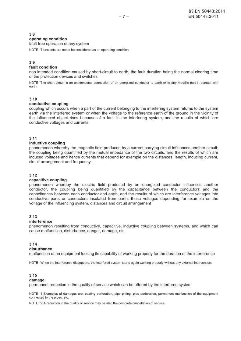
3.8 operating condition fault free operation of any system NOTE Transients are not to be considered as an operating condition.
3.9 fault condition non intended condition caused by short-circuit to earth, the fault duration being the normal clearing time of the protection devices and switches NOTE The short circuit is an unintentional connection of an energized conductor to earth or to any metallic part in contact with earth.
3.10 conductive coupling coupling which occurs when a part of the current belonging to the interfering system returns to the system earth via the interfered system or when the voltage to the reference earth of the ground in the vicinity of the influenced object rises because of a fault in the interfering system, and the results of which are conductive voltages and currents
3.11 inductive coupling phenomenon whereby the magnetic field produced by a current carrying circuit influences another circuit; the coupling being quantified by the mutual impedance of the two circuits, and the results of which are induced voltages and hence currents that depend for example on the distances, length, inducing current, circuit arrangement and frequency
3.12 capacitive coupling phenomenon whereby the electric field produced by an energized conductor influences another conductor, the coupling being quantified by the capacitance between the conductors and the capacitances between each conductor and earth, and the results of which are interference voltages into conductive parts or conductors insulated from earth, these voltages depending for example on the voltage of the influencing system, distances and circuit arrangement
3.13 interference phenomenon resulting from conductive, capacitive, inductive coupling between systems, and which can cause malfunction, disturbance, danger, damage, etc.
3.14 disturbance malfunction of an equipment loosing its capability of working properly for the duration of the interference
NOTE When the interference disappears, the interfered system starts again working properly without any external intervention.
3.15 damage permanent reduction in the quality of service which can be offered by the interfered system
NOTE 1 Examples of damages are: coating perforation, pipe pitting, pipe perforation, permanent malfunction of the equipment connected to the pipes, etc.
NOTE 2 A reduction in the quality of service may be also the complete cancellation of service.

BS EN 50443:2011EN 50443:2011 – 8 –
3.16 interference situation situation in which an interference may appear (permanently or intermittently) between an a.c. power system and a metallic pipeline system, a given interference situation being defined by the geometrical and electrical data of the a.c. power system and of the metallic pipeline system as well as defined by the data describing the medium between the two systems
NOTE An interference situation may cause:
− danger to persons; − damage to the pipeline and/or to the connected equipment; − disturbance of the electrical and/or electronic equipment connected to the pipeline.
3.17 interference distance maximum distance between the pipeline system and a.c. power system for which an interference shall be considered
3.18 interfering current vectorial sum of the currents flowing through the conductors relevant to the a.c. power system (i.e. catenaries, feeders, return conductors, phase conductors, earth wires)
NOTE This interfering current is used to simplify the calculations when the distances between the interfering system and the interfered system is high as compared to the distances between the conductors of the interfering system.
3.19 interference voltage voltage caused on the interfered system by the conductive, inductive and capacitive coupling with the nearby interfering system between a given point and the earth or across an insulating joint
3.20 prospective touch voltage voltage between simultaneously accessible conductive parts when those conductive parts are not being touched by a person or an animal
NOTE In the case dealt in this standard the prospective touch voltage coincides with the interference voltage. This is due to the fact that in the worst case the interfered pipe may not disperse current to ground.
[IEC 60050-195-05-09]
3.21 skilled person person with relevant education and experience to enable him or her to perceive risks and to avoid hazards which electricity can create
[IEC 60050-195-04-01]
3.22 (electrically) instructed person person adequately advised or supervised by electrically skilled persons to enable him or her to perceive risks and to avoid hazards which electricity can create
[IEC 60050-195-04-02] 3.23 immunity ability of a device, equipment or system to perform without degradation in the presence of an electromagnetic disturbance
[IEC 60050-161]
BS EN 50443:2011 – 9 – EN 50443:2011
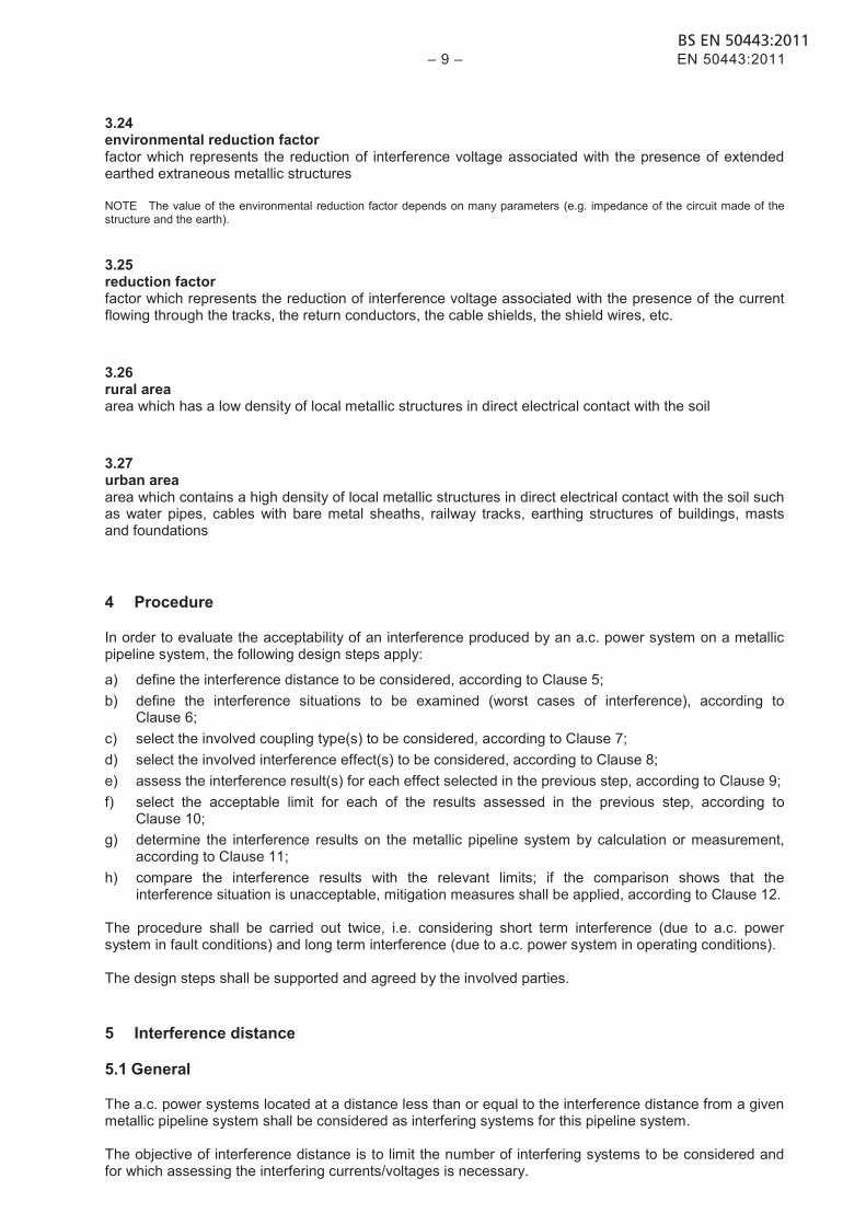
3.24 environmental reduction factor factor which represents the reduction of interference voltage associated with the presence of extended earthed extraneous metallic structures
NOTE The value of the environmental reduction factor depends on many parameters (e.g. impedance of the circuit made of the structure and the earth).
3.25 reduction factor factor which represents the reduction of interference voltage associated with the presence of the current flowing through the tracks, the return conductors, the cable shields, the shield wires, etc.
3.26 rural area area which has a low density of local metallic structures in direct electrical contact with the soil
3.27 urban area area which contains a high density of local metallic structures in direct electrical contact with the soil such as water pipes, cables with bare metal sheaths, railway tracks, earthing structures of buildings, masts and foundations
4 Procedure
In order to evaluate the acceptability of an interference produced by an a.c. power system on a metallic pipeline system, the following design steps apply:
a) define the interference distance to be considered, according to Clause 5; b) define the interference situations to be examined (worst cases of interference), according to
Clause 6; c) select the involved coupling type(s) to be considered, according to Clause 7; d) select the involved interference effect(s) to be considered, according to Clause 8; e) assess the interference result(s) for each effect selected in the previous step, according to Clause 9; f) select the acceptable limit for each of the results assessed in the previous step, according to
Clause 10; g) determine the interference results on the metallic pipeline system by calculation or measurement,
according to Clause 11; h) compare the interference results with the relevant limits; if the comparison shows that the
interference situation is unacceptable, mitigation measures shall be applied, according to Clause 12. The procedure shall be carried out twice, i.e. considering short term interference (due to a.c. power system in fault conditions) and long term interference (due to a.c. power system in operating conditions). The design steps shall be supported and agreed by the involved parties.
5 Interference distance
5.1 General
The a.c. power systems located at a distance less than or equal to the interference distance from a given metallic pipeline system shall be considered as interfering systems for this pipeline system. The objective of interference distance is to limit the number of interfering systems to be considered and for which assessing the interfering currents/voltages is necessary.
BS EN 50443:2011EN 50443:2011 – 10 –
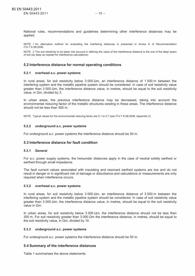
National rules, recommendations and guidelines determining other interference distances may be applied. NOTE 1 An alternative method for evaluating the interfering distances is presented in Annex A of Recommendation ITU-T K.68:2008.
NOTE 2 The soil resistivity to be taken into account in defining the value of the interference distance is the one of the deep layers of soil (as deep as needed for interference calculations).
5.2 Interference distance for normal operating conditions
5.2.1 overhead a.c. power systems
In rural areas, for soil resistivity below 3 000 Ωm, an interference distance of 1 000 m between the interfering system and the metallic pipeline system should be considered. In case of soil resistivity value greater than 3 000 Ωm, the interference distance value, in metres, should be equal to the soil resistivity value, in Ωm, divided by 3. In urban areas, the previous interference distance may be decreased, taking into account the environmental reducing factor of the metallic structures existing in these areas. The interference distance should not be less than 300 m. NOTE Typical values for the environmental reducing factor are 0,1 to 0,7 (see ITU-T K.68:2008, Appendix II).
5.2.2 underground a.c. power systems
For underground a.c. power systems the interference distance should be 50 m. 5.3 Interference distance for fault condition
5.3.1 General
For a.c. power supply systems, the hereunder distances apply in the case of neutral solidly earthed or earthed through small impedance. The fault current values associated with insulating and resonant earthed systems are low and do not result in danger or in significant risk of damage or disturbance and calculations or measurements are only required when interference occurs. 5.3.2 overhead a.c. power systems
In rural areas, for soil resistivity below 3 000 Ωm, an interference distance of 3 000 m between the interfering system and the metallic pipeline system should be considered. In case of soil resistivity value greater than 3 000 Ωm, the interference distance value, in metres, should be equal to the soil resistivity value in Ωm. In urban areas, for soil resistivity below 3 000 Ωm, the interference distance should not be less than 300 m. For soil resistivity greater than 3 000 Ωm the interference distance, in metres, should be equal to the soil resistivity value, in Ωm, divided by 10. 5.3.3 underground a.c. power systems
For underground a.c. power systems the interference distance should be 50 m. 5.4 Summary of the interference distances
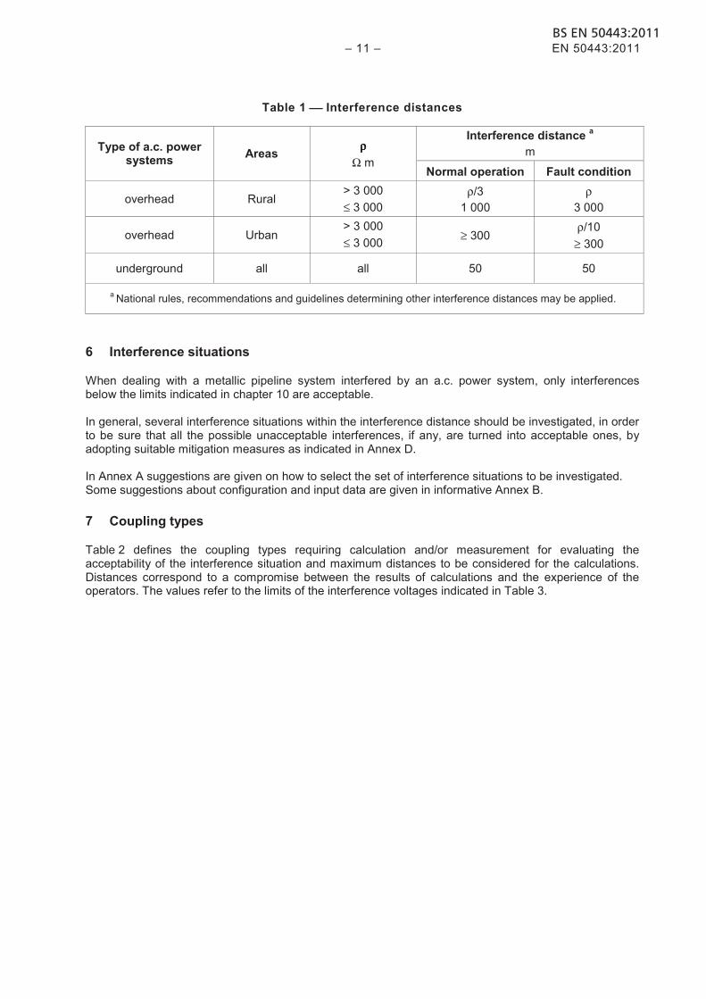
Table 1 summarises the above statements.
BS EN 50443:2011 – 11 – EN 50443:2011
Table 1 Interference distances
Type of a.c. power systems Areas ρρρρ
Ω m
Interference distance a m
Normal operation Fault condition
overhead Rural > 3 000 ≤ 3 000
ρ/3 1 000
ρ 3 000
overhead Urban > 3 000 ≤ 3 000 ≥ 300
ρ/10 ≥ 300
underground all all 50 50
a National rules, recommendations and guidelines determining other interference distances may be applied.
6 Interference situations
When dealing with a metallic pipeline system interfered by an a.c. power system, only interferences below the limits indicated in chapter 10 are acceptable. In general, several interference situations within the interference distance should be investigated, in order to be sure that all the possible unacceptable interferences, if any, are turned into acceptable ones, by adopting suitable mitigation measures as indicated in Annex D. In Annex A suggestions are given on how to select the set of interference situations to be investigated. Some suggestions about configuration and input data are given in informative Annex B.
7 Coupling types
Table 2 defines the coupling types requiring calculation and/or measurement for evaluating the acceptability of the interference situation and maximum distances to be considered for the calculations. Distances correspond to a compromise between the results of calculations and the experience of the operators. The values refer to the limits of the interference voltages indicated in Table 3.

BS EN 50443:2011EN 50443:2011 – 12 –
Table 2 Coupling types and distances to be considered
Metallic pipeline system
Above ground Underground
Not electrically connected to earth
Electrically connected to earth
Normal operation
Fault condition
Normal operation
Fault condition
Normal operation
Fault condition
Inductive f
Capacitive a b
---
Inductive f
---
---
Inductive f
---
Conductive c d
Inductive f
---
Conductive c e
Inductive f
---
Conductive c d
Inductive f
---
Conductive c e
a Capacitive coupling from a railway system has to be considered in case of proximity lower than: - 10 m in case of 15 kV, 16,7 Hz systems; - 50 m in case of 25 kV, 50 Hz systems.
b Capacitive coupling from a.c. power supply systems shall be considered in case of proximity lower than 100 m. c Conductive coupling from an a.c. electric traction system shall be considered in case of crossing or proximity lower than 5 m from
the nearest rail or masts or metallic components connected to the rails. For faults in the HV side of an a.c. substation supplying an a.c. electric traction system, conductive coupling shall be considered
in case of proximity lower than 150 m from the earthing grid. d Not to be considered for the a.c. power supply systems. e To prevent damages to the pipeline or to the connected equipment, the following conditions apply:
Conductive coupling from a.c. power supply systems shall be considered in case of proximity lower than: - 5 m from the closest visible part of the tower of a HV power line rated at 50 kV or less; - 20 m from the closest visible part of the tower of a HV power line provided with earth wire(s) with nominal voltage greater than
50 kV; - 100 m from the closest visible part of the tower of a HV power line not provided with earth wire(s) with nominal voltage greater
than 50 kV; - 20 m from earthing systems of HV power cables with nominal voltage greater than 50 kV; - 150 m from the earthing grid of a power substation. In any case a minimum distance of 2 m from the closest part of the earthing system of a tower shall be observed. To guarantee the electrical safety of persons, in case any metallic part connected to the pipeline is accessible to them, conductive coupling has to be considered within the interference distance defined in Clause 5.
f The interference distances are equal to the ones indicated in Clause 5.
NOTE It is assumed that fault current values associated with insulating and resonant earthed systems are low and do not result in danger or in significant risk of damage or disturbance and calculations or measurements are only required when interference occurs.
For pipelines without longitudinal electrical continuity, e.g. cast iron pipelines, interference effects are usually negligible.
8 Interference
The effects to be considered are the following:
a) danger to persons who come in direct contact or contact through conductive parts with the metallic pipeline system or with the connected equipment;
b) damage to the pipeline or to the connected equipment; c) disturbance of electrical/electronic equipment, connected to the pipeline. The pipeline company shall apply electrical/electronic systems such that they will not react in dangerous ways, nor in ways which will stop production, to the short duration voltages not exceeding the values defined in paragraph 10.3.1 and currents which appear during short circuits on the a.c. power system.
BS EN 50443:2011 – 13 – EN 50443:2011
9 Interference results
The following interference results shall be evaluated:
a) for danger to persons who come in direct contact or in contact through conductive parts with the metallic pipeline system or to the connected equipment, the voltage to earth of the pipeline and the voltage difference on the insulating joints shall be evaluated in normal operation and in fault conditions;
b) for damage to pipeline or to the connected equipment, the voltage to earth of the pipeline and the
voltage difference on the insulating joints shall be evaluated in normal operation and in fault conditions;
c) for disturbance of electric/electronic equipment connected to the pipeline the voltage across the
electric/electronic equipment connected to the pipeline at the connection points shall be evaluated in normal operation only.
10 Limits for permissible interference
10.1 General
Limits given in the following clauses apply:
− to the total interference result, produced on a single pipeline, or pipeline system, by all the a.c. interfering systems acting together, when considering the operating conditions of the interfering sources;
− to the interference result, produced on a single pipeline, or pipeline system, by a single a.c. interfering system acting alone, when considering the fault conditions of the interfering system.
NOTE An interfering system may be composed of many interconnected lines.
10.2 Limits related to electrical safety of persons
10.2.1 General
The limits stated in 10.2.2 and in 10.2.3:
− apply to those parts of the metallic pipeline or connected equipment normally accessible to (electrically) instructed persons, all along the pipeline,
− refer to instructed persons with common clothing, without particular individual protection means other than shoes with an insulating resistance not less than 3 000 Ω. In case of use of individual protection means a specific study shall evaluate the admissible values for the interference voltages, which can be higher than the ones given in 10.2.2 and in 10.2.3.
The permissible voltages given in 10.2.2 and in 10.2.3 are in accordance with typical situation and working procedures (see ITU-T K.68).
In case of more severe situations (wet conditions, narrow working space, repairing operations, etc.) or where common people (i.e. neither electrically instructed nor skilled persons) may come in contact with the pipeline in operating conditions, additional precautions should be taken into consideration (e.g. reduce admissible voltage, use of insulating coverings, special instruction to personnel, etc). The voltage to ground limits hereunder specified refer to interference voltages. 10.2.2 Operating conditions
The interference voltage (r.m.s. value) of the pipeline system versus earth or across the insulating joints at any point normally accessible to any person (see 10.2.1) shall not exceed 60 V.
BS EN 50443:2011EN 50443:2011 – 14 –
10.2.3 Fault conditions
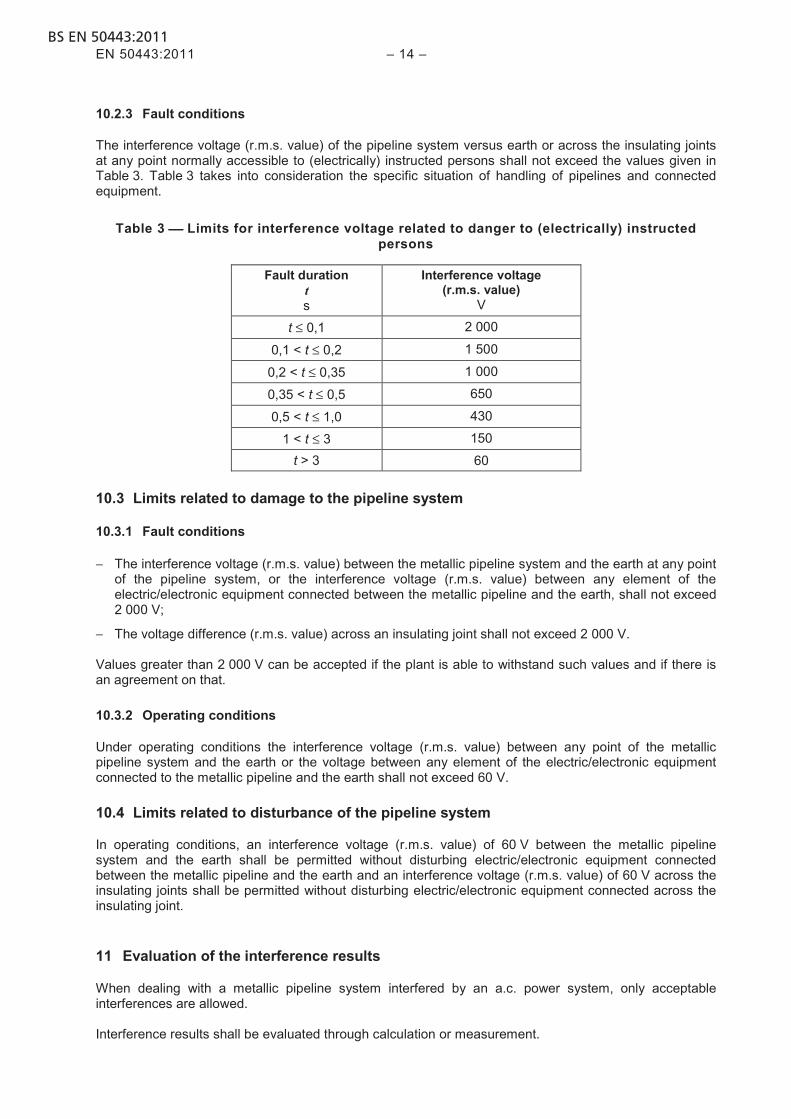
The interference voltage (r.m.s. value) of the pipeline system versus earth or across the insulating joints at any point normally accessible to (electrically) instructed persons shall not exceed the values given in Table 3. Table 3 takes into consideration the specific situation of handling of pipelines and connected equipment.
Table 3 Limits for interference voltage related to danger to (electrically) instructed persons
Fault duration t s
Interference voltage (r.m.s. value)
V
t ≤ 0,1 2 000
0,1 < t ≤ 0,2 1 500
0,2 < t ≤ 0,35 1 000
0,35 < t ≤ 0,5 650
0,5 < t ≤ 1,0 430
1 < t ≤ 3 150
t > 3 60 10.3 Limits related to damage to the pipeline system
10.3.1 Fault conditions
− The interference voltage (r.m.s. value) between the metallic pipeline system and the earth at any point of the pipeline system, or the interference voltage (r.m.s. value) between any element of the electric/electronic equipment connected between the metallic pipeline and the earth, shall not exceed 2 000 V;
− The voltage difference (r.m.s. value) across an insulating joint shall not exceed 2 000 V. Values greater than 2 000 V can be accepted if the plant is able to withstand such values and if there is an agreement on that. 10.3.2 Operating conditions
Under operating conditions the interference voltage (r.m.s. value) between any point of the metallic pipeline system and the earth or the voltage between any element of the electric/electronic equipment connected to the metallic pipeline and the earth shall not exceed 60 V. 10.4 Limits related to disturbance of the pipeline system
In operating conditions, an interference voltage (r.m.s. value) of 60 V between the metallic pipeline system and the earth shall be permitted without disturbing electric/electronic equipment connected between the metallic pipeline and the earth and an interference voltage (r.m.s. value) of 60 V across the insulating joints shall be permitted without disturbing electric/electronic equipment connected across the insulating joint.
11 Evaluation of the interference results
When dealing with a metallic pipeline system interfered by an a.c. power system, only acceptable interferences are allowed. Interference results shall be evaluated through calculation or measurement.
BS EN 50443:2011 – 15 – EN 50443:2011
Each company involved in the interference is responsible for providing correct data relevant to its systems involved. Some suggestions concerning input data and calculation are given in Annex B. Measurements are also used to evaluate the interference results. Measurement results can be directly compared with the limits only if the measurements are performed in the same interference condition to which limits apply. If this is not the case, measurements require a suitable elaboration based on calculation methods and on measurements performed at the same time on both the a.c. power system and the pipeline system. Some suggestions concerning measurement methods are given in Annex C. The calculation methods and the measurement methods shall be agreed between the power and/or railway infrastructure manager and the pipeline company. Where measurements are to be carried out, they shall be coordinated between the involved parties. To take into account all the electromagnetic interferences acting together see Annex B.
12 Mitigation measures
In case interference results exceed the limits, mitigation measures shall be agreed on by the involved parties, in order to make the interference situation acceptable. NOTE Which measures are taken and whether the measures are taken on the interfering or on the interfered system, will depend on the significance of the interference, the impact in terms of safety, equipment damage and malfunction, cost and complexity of mitigation options and the party introducing the change.
Some suggestions concerning mitigation measures are given in Annex D.

BS EN 50443:2011EN 50443:2011 – 16 –
Annex A (informative)
Indications to select interference situations
The scope of the interference evaluation and mitigation is to get assurance that only acceptable interferences occur. In general, several interference situations should be investigated within the interference distance, in order to be sure that all the possible unacceptable interferences, if any, are turned into acceptable ones, by adopting suitable mitigation measures. In general it is impossible to give rules for defining the set of interference situations to be examined. During the design procedure it is necessary to examine an adequate set of interference situations in order to be sure that, after the design stage, unacceptable interferences exist no more. In some cases, characterized by simple configurations of the involved systems, it can be possible to define a priori, before making interference calculations, the worst interference situation, resulting in the highest value of interference results. This is the case, e.g., of fault condition on “simple” power systems (e.g. a simple a.c. railway line is the one where trains are fed by the contact wire only and the current return is made through rails and earth only, without special arrangements like return conductors, booster transformers or autotransformers), where, usually, the worst fault position is the one corresponding to the one of the ends of the exposure zone. In the majority of cases the worst interference situation can be evaluated only after making several calculations. Thus in the design procedure an adequate set of calculations has to be selected in order to be sure that it comprises the worst case. Interference problems can arise not only when the metallic pipeline system is completed, but also during the installation stage, even if at that stage only some parts of the whole metallic pipeline system are involved in the coupling phenomena.
BS EN 50443:2011 – 17 – EN 50443:2011
Annex B (informative)
Guidance for interference investigations
B.1 Introduction
It should be considered that a calculation method able to evaluate the results of interference requires a lot of input data and a variety of algorithms. Thus it is impossible to give a description of one or more calculation methods as a normative part of this standard. This is the reason why we give in this informative Annex B some suggestions only, which can be used to carefully select, according to the interference problem to be solved, the specific calculation method to be used. If national rules concerning calculations exist, they should be applied. B.2 Configuration of the a.c. electric traction system
B.2.1 General As a general rule, the closer the inducing railway line is to the induced pipeline, the greater the number of parameters describing the railway line is required. The fundamental parameters to be known for evaluating at one frequency the interference results should be:
a) in case the approach distance is less than 100 m and the length of parallelism is greater than 1 000 m within this distance:
1) the current flowing in all relevant conductors and tracks for the considered frequency;
2) the geometrical position of all relevant conductors;
3) the geographic position of the line;
b) in other cases, when the distance between railway line and pipeline is longer:
1) the interfering current for the considered frequency;
2) the geographic position of the line.
Instead of the current flowing in the tracks or in conductors other than the contact wire, the relevant reduction factors may be used. NOTE Typical values for these reduction factors are given in recommendation ITU-T K.68:2008, Appendix II.
Calculations are performed on railway lines that show constant and homogeneous characteristics or on which average values of parameters may be assumed along the considered length. If this is not the case the railway lines should be divided in sections until this applies. In that case, the above mentioned parameters should be provided for each railway line section. NOTE When dealing with a non homogeneous line the usual procedure is to divide the line into homogeneous sections and combine, manually or automatically if a computation tool is available, the contributions to the interfering voltage by each line section.
B.2.2 Configuration under operating conditions The railway company should provide for the fundamental power frequency all parameters defined in B.2.1.
BS EN 50443:2011EN 50443:2011 – 18 –
B.2.3 Configuration under fault conditions The railway company should provide for the fundamental frequency all parameters defined in B.2.1 for all positions of short circuit to be considered. B.3 Configuration of the a.c. power supply system
B.3.1 General As a general rule, the closer the inducing a.c. power supply line is to the induced pipeline, the greater the number of parameters describing the a.c. power supply line is required. The fundamental parameters to be known for evaluating at one frequency the interference results should be:
a) in case the approach distance is less than 100 m and the length of parallelism is greater than 1 000 m within this distance:
1) the current flowing in all conductors for the considered frequency;
2) the geometrical positioning of all conductors;
3) the geographic positioning of the line;
b) in other cases, when the distance between a.c. power supply line and pipeline is longer:
1) the interfering current for the considered frequency;
2) the geographic positioning of the line.
Instead of the current flowing in the sheaths (in case of a.c. power supply lines in cables) and/or in earth wires (in case of overhead a.c. power supply lines), the relevant reduction factors may be used. NOTE 1 Typical values for these reduction factors are given in recommendation ITU-T K.68:2008, Appendix II.
Calculations are performed on a.c. power supply lines that show constant and homogeneous characteristics or on which average values of parameters may be assumed along the considered length. If this is not the case the a.c. power supply lines should be divided in sections on which this applies. In that case, the abovementioned parameters should be provided for each a.c. power supply line section. NOTE 2 When dealing with a non homogeneous line the usual procedure is to divide the line into homogeneous sections and combine, manually or automatically if a computation tool is available, the contributions to the interfering voltage by each line section.
B.3.2 Configuration under operating conditions The a.c. power supply company should provide for the fundamental power frequency all parameters defined in B.3.1. B.3.3 Configuration under fault conditions The a.c. power supply company should provide for the fundamental frequency all parameters defined in B.3.1 for all positions of short circuit to be considered. B.4 Configuration of the pipeline
B.4.1 General In view of unacceptable interference on pipeline systems, due to a.c. power systems, the configurations of a metallic pipeline and of connected equipment have to be considered from the electrical point of view. The parameters to be taken into account refer to the electrical behaviour of the pipeline to the
BS EN 50443:2011 – 19 – EN 50443:2011
environment (coating, soil, etc.) and to the electrical behaviour between different parts of the pipeline (equipotential bondings, insulating joints, electrical drainages, a.c. discharge devices, earthing, etc.). Electrical, electronic and cathodic protection equipment should be considered for the interference they can resist before malfunction (controlling, measuring, etc.) or damage occurs. For a new pipeline, characteristics and location of pipeline sections and connected equipment should be considered in design conditions, including all the mounted safety devices. For an existing pipeline the actual electrical configuration should be considered. The pipeline company should provide all information about the configuration as built of the pipeline system. B.4.2 Parameters to be considered For all metallic pipelines and/or connected equipment within the interference distance, the parameter hereafter are the main ones to estimate the results of interference and the data (in some cases average values are enough) should be provided by the pipeline company:
− the geographical positioning of the pipeline; − the pipeline length (km); − the burial depth of the pipeline (m); − the pipeline outer diameter (mm); − the wall thickness of the pipeline (mm); − the insulating coating thickness (mm); − the insulating resistance of the coating (Ωm²); − the pipeline resistivity (Ωmm2/km or Ωm); − the pipeline magnetic permeability; − the electrical characteristics of the transported medium; − soil resistivity (Ωm) of the deep layers of soil (as deep as needed for interference calculations); − the location of complex structures (as defined in EN 14505) and their values of the resistance to earth; − the location and the characteristics of different devices connected to the pipeline (as earth
connections, surge protecting devices (SPD)), electrical and/or electronic equipment, cathodic protection devices, shielding metallic structures, insulating joints and connected apparatus, etc.). Characteristics means the electrical description of the behaviour of the equipment under interference (linear/non-linear, impedance, immunity at the main frequency, resistibility, etc.).
Calculations are performed on pipelines that show constant and homogeneous characteristics or on which average values of parameters may be assumed along the considered length. If this is not the case pipelines should be divided in sections until this applies. In that case, the abovementioned parameters should be provided for each pipeline section. NOTE When dealing with a non homogeneous pipeline the usual procedure is to divide the pipeline into homogeneous sections and combine, manually or automatically if a computation tool is available, the contributions to the interfering voltage on each pipeline section.
B.5 Calculation methods
The two references given hereinafter cover the problem. CIGRE published in 1995 the Guide on the Influence of High Voltage AC Power Systems on Metallic Pipelines. It shows in a condensed way the key elements for the calculation but, of course, it does not deal with the railway lines. Most of this publication is derived from the ITU-T Directives concerning the protection of telecommunication lines against harmful effects from electric power and electrified railway lines. Such a publication was issued by ITU (previously named CCITT) Directives concerning the protection of telecommunication lines against harmful effects from electric power and electrified railway lines and consists of nine volumes.
BS EN 50443:2011EN 50443:2011 – 20 –
These volumes have been established by the CCITT in close cooperation with, and with the agreement of, the International Conference on Large High Voltage Electric Systems (CIGRE) and the International Union of Railways (UIC). Among these volumes, Volume II (approximate calculation methods) and Volume III (theory and precise calculation methods) deal with the calculation in general. Volume IV and Volume V deal with the specific applications to a.c. electric traction systems and to a.c. power supply systems respectively. B.6 Calculation of independent interfering systems
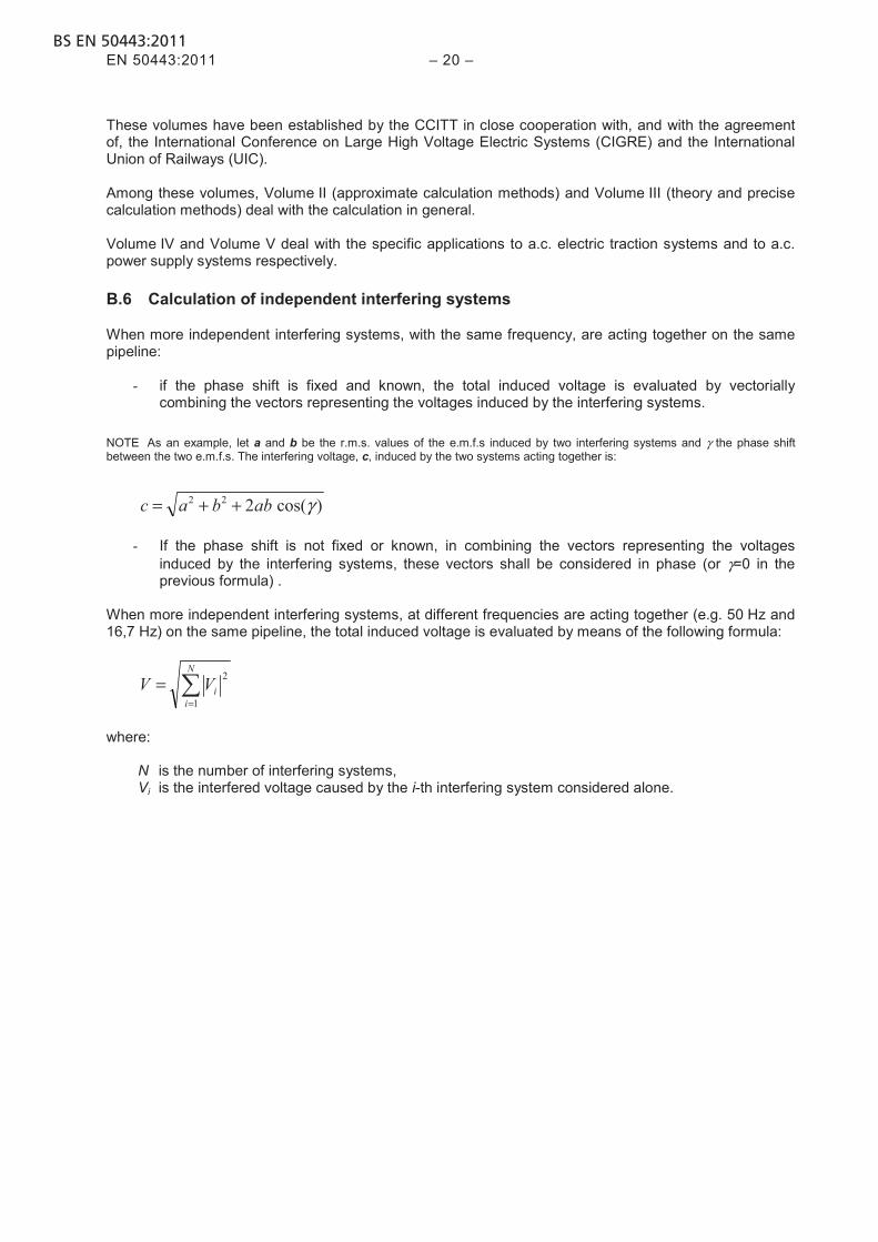
When more independent interfering systems, with the same frequency, are acting together on the same pipeline:
- if the phase shift is fixed and known, the total induced voltage is evaluated by vectorially combining the vectors representing the voltages induced by the interfering systems.
NOTE As an example, let a and b be the r.m.s. values of the e.m.f.s induced by two interfering systems and γ the phase shift between the two e.m.f.s. The interfering voltage, c, induced by the two systems acting together is:
)cos(222 γabbac ++=
- If the phase shift is not fixed or known, in combining the vectors representing the voltages induced by the interfering systems, these vectors shall be considered in phase (or γ=0 in the previous formula) .
When more independent interfering systems, at different frequencies are acting together (e.g. 50 Hz and 16,7 Hz) on the same pipeline, the total induced voltage is evaluated by means of the following formula:
∑=
=N
iiVV
1
2
where:
N is the number of interfering systems, Vi is the interfered voltage caused by the i-th interfering system considered alone.

BS EN 50443:2011 – 21 – EN 50443:2011
Annex C (informative)
Measuring methods
C.1 General
The quantities to be measured to quantify the amount of an interference are voltages and currents, thus they are normal quantities involved in any electrical problem. Other quantities involved in the measurements can be the resistance of a conductor, the resistance of an earth electrode, the soil resistivity. In this sense there is nothing particular to be suggested, except to perform such measurements according to the relevant standards, if any. When measuring voltages to earth, the connection to the earth should be perpendicular to the line of the interfering system, or else allowance should be made for induced voltages in the connection. As a reference it is possible to use the Volume IX of the ITU-T Directives mentioned in Annex B. Some measurements are described in HD 384.6.61. As mentioned in Clause 11, sometimes measurements of the interference results on the pipeline must be related to the inducing quantities measured at the same time on the interfering system. C.2 Measurement methods for interference voltages at steady state
In order to get the interference voltage a voltmeter with a high internal resistance is suitable connected:
− between a given point of the influenced pipeline system and a 10 cm deep-driven earth sensor or an existing earth system;
− across an insulating joint of the influenced pipeline system.

BS EN 50443:2011EN 50443:2011 – 22 –
Annex D (informative)
Mitigation measures
D.1 General
In order to reduce the effects of the interference, a comprehensive mitigation measure consists in placing the interfering system and the pipeline far enough apart from each other: the distance depends on the inducing current, the soil resistivity and the length of the parallelism. When it is not possible to achieve sufficient separation distance, specific mitigation measures should be considered, these may be implemented on the pipeline system, on the a.c power system or both. When provided at the design stage the effort for implementing a mitigation measure is usually much lower than when provided later. In choosing where to install the protective measures it should be considered that any protective device at the a.c. power system side is in general more expensive than measures that can be applied to the interfered pipeline. It should be carefully considered how mitigation measures can influence the whole design of the pipeline infrastructure. D.2 Mitigation measures at the pipeline side
D.2.1 Screening structures Screening structures are used to prevent conductive coupling. They consist in: − insulating coating structures close to the pipeline, not to allow the a.c. power system current to return
via the pipeline structure; − conductive structures close to the pipeline, bringing locally the remote earth potential. D.2.2 Surge protective devices (SPD) SPD can be used to connect the pipeline to earth or to connect the opposite sides of an insulating joint in order to reduce the amount of the voltages appearing in case of fault conditions or in very peculiar heavy operating conditions. It should be considered that when installed between the pipeline and the earth, an earthing connection is required, having a very low impedance. It should also be considered that it is necessary to have a suitable separation between the maximum continuous operating voltage of the SPD and the maximum induced voltage in operating conditions. D.2.3 Insulating joints Insulating joints can be inserted at intervals along the pipeline in order to provide electrical discontinuity for reducing the lengths of pipeline which are subject to induction, thereby reducing the length of exposure. D.2.4 Earthing Earth connections can be used to reduce the amount of induced voltages in fault conditions and in operating conditions. Earthing will reduce the induced voltages, but at the same time currents along the pipeline will increase. In general this is not a problem, but users should be aware of this effect.

BS EN 50443:2011 – 23 – EN 50443:2011
D.3 Mitigation measures at the a.c railway system side
D.3.1 General The scope of the mitigation measures taken at the railway side is to reduce the interfering current. In the following possible methods for reduction of the interference voltages are indicated. D.3.2 Earth conductors and return conductors These are conductors mounted on the overhead line structures or underground, connected to the rails at regular intervals. D.3.3 Booster transformers The booster transformers, placed at intervals along the line, provide a coupling between the overhead contact wire and the rails or a booster return conductor. The use of booster transformers provide suppression at source thereby reducing the loop area presenting a more balanced system as a result of outgoing and return magnetic field cancellation. The disadvantage of such a system is that it results in higher line impedance which requires a shorter distance between substations. The principle of booster transformers is described in the ITU-T Directives, Volume IV. D.3.4 Autotransformers Feeding a railway line through autotransformers has the following results:
− out of the section occupied by the train, the feeding current flows back to the substation mainly through the negative feeder;
− inside the section occupied by the train, the current flows in both the directions from the train position in the contact wire and in the rails, in one direction in the negative feeder;
thus the interference situation is more favourable with respect to the feeding system without autotransformers. This feeding system allows for a higher distance among substations as the energy is mainly conveyed at a voltage which is the double of the one of the contact wire. The calculation of voltages and currents in such a system requires a suitable algorithm. The principle of autotransformers is described in the ITU-T Directives, Volume IV. NOTE This method can be considered only for the design stage not for railway systems existing and using other schemes.
D.4 Mitigation measures at the a.c. power supply system side
Modifying the phases arrangement, as well as splitting or transposing them, could reduce the interference results relevant to the operating conditions of the a.c. power line. For the purpose of reducing interference in fault conditions, additional earth wires can be used.
BS EN 50443:2011EN 50443:2011 – 24 –
Annex E (informative)
Management of interference
E.1 General
Each interference situation deals with the safety of persons, damage to plant or malfunction of plant. E.2 Plant life
It should be remembered that the technical characteristics of a plant often vary during the plant life: as a consequence also the severity of an interference can vary during the plant life. A critical situation happens when, due to modifications of the technical characteristics of a plant, an acceptable interference evolves to an unacceptable one: this should be avoided by a suitable monitoring of the evolution of the technical characteristics of the plants involved in the interference. E.3 Exchange of information
As an interference situation typically involves two plants of different companies, it is necessary to establish an efficient and reliable exchange of information between the two companies. Moreover it should be considered that a pipeline can be interfered by several interfering systems belonging to various owners as well as an a.c power system can produce interference to several interfered systems belonging to various owners. This means that a correct, reliable and timely exchange of information is highly important. A possible way to manage this aspect is that each company should appoint an interference manager which has the complete overview of all the interference problems pertaining to the company, in order to be the reference point for each exchange of information related to the interferences pertaining to the company. E.4 Plant documentation
A possible way to keep under control the interference situations is to maintain a technical dossier on interference for each plant. This dossier could be arranged in the form of as many sub-dossier as the interference situations are for the plant: it means that a pipeline dossier will contain as many sub-dossier as the inducing plants are, while an a.c. power system dossier will contain as many sub-dossier as the interfered plants are. Each sub-dossier should contain all the documents related to the problem, e.g.:
− the contacts with all the owners of the inducing plants (in case of a pipeline dossier) or the owners of the interfered plants (in case of an a.c power system dossier) in order to leave memory on how and from where the data have been collected;
− the geometrical and electrical descriptions of the plants involved in the interference; − the results of calculations performed (one calculation if the interference is acceptable since the
beginning: several calculations if the interference was not acceptable at the beginning, thus the mitigation measures design was necessary): the dossier should leave memory of such design,
− the results of measurements performed, if any; − any other document dealing with the agreements between the owners of the plants, relevant to the
sharing of the costs of interference, if any.

BS EN 50443:2011 – 25 – EN 50443:2011
Each sub-dossier should be independent and complete. As well as the plant characteristics can vary during the plant life, also an interference dossier of a plant can vary during the plant life, thus it could be necessary to add new documents (documents can only be added to a dossier) to leave memory of the plant history.
BS EN 50443:2011EN 50443:2011 – 26 –
Annex F (informative)
A-deviations
A-deviation: National deviation due to regulations, the alteration of which is for the time being outside the competence of the CEN/CENELEC national member. This European Standard does not fall under any Directive of the EC. In the relevant CEN/CENELEC countries these A-deviations are valid instead of the provisions of the European Standard until they have been removed. Clause Deviation 4 Switzerland
Ordinance to Electrical Lines (Leitungsverordnung LeV, SR 734.31) Section 5: close proximity, parallel routing and intersections of electrical lines with pipeline installations within the articles (paragraphs) 123 to 128 deals with the procedure in clause 4 of EN 50433.
10.2.3 Switzerland Ordinance to power installations (Starkstromverordnung, SR 734.2) Annex 4: Admissible touch Voltages The admissible touch voltages in Switzerland have to follow the values in annex 4 in the ordinance and not those in table 3 in clause 10.2.3 of EN 50443.

BS EN 50443:2011 – 27 – EN 50443:2011
Bibliography
EN 14505, Cathodic protection of complex structures EN 50110-1, Operation of electrical installations EN 50122-1, Railway applications Fixed installations Electrical safety, earthing and the return circuit Part 1: Protective provisions against electric shock HD 384.6.61 S2:2003, Electrical installations of buildings Part 6-61: Verification Initial verification (IEC 60364-6-61:1986, mod. + A1:1993 + A2:1997, mod.) ITU-T Directives concerning the protection of telecommunication lines against harmful effects from electric power and electrified railway lines
− Volume I [ed.1990]: “Design, construction and operational principles of telecommunication, power and electrified railway facilities” (ISBN 92-61-03941-3)
− Volume II [ed.1999]: “Calculating induced voltages and currents in practical cases” (ISBN 92-61-08001-4)
− Volume III [ed.1990]: “Capacitive, inductive and conductive coupling: physical theory and calculation methods” (ISBN 92-61-04041-1)
− Volume IV [ed.1990]: “Inducing currents and voltages in electrified railway systems” (ISBN 92-61-04051-9)
− Volume V [ed.2008]: “Inducing currents and voltages in power transmission and distribution systems” (ISBN 92-61-12491-7)
− Volume VI [ed.2008]: “Danger, damage and disturbance” (ISBN 92-61-12501-8) − Volume VII [ed.1990]: “Protective measures and safety precautions” (ISBN 92-61-04081-0) − Volume VIII [ed.1990]: “Protective devices” (ISBN 92-61-04091-8) − Volume IX [ed.1989]: “Testing methods and measuring apparatus” (ISBN 92-61-04101-9)
ITU-T K.68:2008, Management of electromagnetic interference on telecommunication systems due to power systems and operators' responsibilities CIGRE (1995), Guide on the influence of the high voltage AC power system on metallic pipelines

This page deliberately left blank

This page deliberately left blank
BSI is the independent national body responsible for preparing British Standards and other standards-related publications, information and services. It presents the UK view on standards in Europe and at the international level.
BSI is incorporated by Royal Charter. British Standards and other standardisation products are published by BSI Standards Limited.
British Standards Institution (BSI)
raising standards worldwide™
BSI
389 Chiswick High Road London W4 4AL UK
Tel +44 (0)20 8996 9001Fax +44 (0)20 8996 7001www.bsigroup.com/standards
RevisionsBritish Standards and PASs are periodically updated by amendment or revision. Users of British Standards and PASs should make sure that they possess the latest amendments or editions.
It is the constant aim of BSI to improve the quality of our products and services. We would be grateful if anyone finding an inaccuracy or ambiguity while using British Standards would inform the Secretary of the technical committee responsible, the identity of which can be found on the inside frontcover. Similary for PASs, please notify BSI Customer Services.
Tel: +44 (0)20 8996 9001 Fax: +44 (0)20 8996 7001
BSI offers BSI Subscribing Members an individual updating service called PLUS which ensures that subscribers automatically receive the latest editions of British Standards and PASs.
Tel: +44 (0)20 8996 7669 Fax: +44 (0)20 8996 7001Email: [email protected]
Buying standardsYou may buy PDF and hard copy versions of standards directly using acredit card from the BSI Shop on the website www.bsigroup.com/shop.In addition all orders for BSI, international and foreign standards publicationscan be addressed to BSI Customer Services.
Tel: +44 (0)20 8996 9001 Fax: +44 (0)20 8996 7001Email: [email protected]
In response to orders for international standards, BSI will supply the British Standard implementation of the relevant international standard, unless otherwise requested.
Information on standardsBSI provides a wide range of information on national, Europeanand international standards through its Knowledge Centre.
Tel: +44 (0)20 8996 7004 Fax: +44 (0)20 8996 7005Email: [email protected]
BSI Subscribing Members are kept up to date with standards developments and receive substantial discounts on the purchase priceof standards. For details of these and other benefits contact Membership Administration.
Tel: +44 (0)20 8996 7002 Fax: +44 (0)20 8996 7001 Email: [email protected]
Information regarding online access to British Standards and PASs via British Standards Online can be found at www.bsigroup.com/BSOLFurther information about British Standards is available on the BSI website at www.bsi-group.com/standards
CopyrightAll the data, software and documentation set out in all British Standards and other BSI publications are the property of and copyrighted by BSI, or some person or entity that own copyright in the information used (such as the international standardisation bodies) has formally licensed such information to BSI for commerical publication and use. Except as permitted under the Copyright, Designs and Patents Act 1988 no extract may be reproduced, stored in a retrieval system or transmitted in any form or by any means – electronic, photocopying, recording or otherwise – without prior written permission from BSI. This does not preclude the free use, in the course of implementing the standard, of necessary details such as symbols, and size, type or grade designations. If these details are to be used for any other purpose than implementation then the prior written permission of BSI must be obtained. Details and advice can be obtained from the Copyright & Licensing Department.
Tel: +44 (0)20 8996 7070Email: [email protected]