effective depth of regular wave on submerged...
TRANSCRIPT

International Robotics & Automation Journal
Effective Depth of Regular Wave on Submerged Submarines and AUVs
Submit Manuscript | http://medcraveonline.com
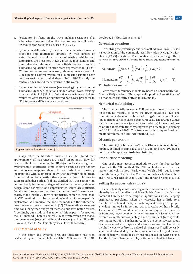
between two fluids of different density. Orbital motion dies out quickly below the surface. At some depth below the surface, the circular orbits become so small that motion is negligible. This depth is called the “Wave Base”. Wave base can be regarded equal to one-half the wavelength (λ/2) measured from still water level (Figure 1). Only wave length controls the depth of the wave base, so the longer the wave, the deeper the wave base. The decrease of orbital motion with depth has many practical applications. For instance, submarines can avoid large ocean waves simply by submerging below the wave base. Even the largest storm waves will go unnoticed if a submarine submerges to only 150 meters [1]. Floating bridges and floating oil rigs are constructed so that most of their mass is below wave base, so they will be unaffected by wave motion. In fact offshore floating airport runways have been designed using similar principles. Additionally, seasick scuba divers find relief when they were submerged into the calm, motionless water below wave base [1]. Therefore, deep water defines as depth more than λ/2. The hydrodynamic forces of ocean surface wave on the submerged bodies are studied in a number of fields of engineering such as:
a. Offshore engineering: wave effects on the vertical and horizontal fixed cylinders such as the structural members of platform leg. Many extended studies have been performed to analyzing diffraction around a submerged fixed cylinder. Thus Dean [2], used a linearized potential theory, for showing the reflection effects. Ursell [3] and later Ogilvie [4] presented the formulation of wave steepness up to the second order. Chaplin [5] measured the nonlinear force on a fixed horizontal cylinder beneath waves by an experimental
method. He analyzed the influence of the Keulegan-Carpenter number on the harmonics of the applied force.
b. Wave Energy Converter (WEC): wave effects on the moored or prescribed motions of cylinders of energy converter just near the surface. It is either interesting in offshore engineering for moored semi-submersibles [6-10]. Wu [7] presented a formulation for calculating the forces exerted on a submerged cylinder undergoing large-amplitude motions. The free surface condition is linearized and the body surface condition is satisfied on its instantaneous position. The solution for the potential is stated as multi-pole expansion. Wu obtained results for a circular cylinder in purely vertical motion and clock-wise circular motion in a wave field Wu [7].
c. Submarine and submersible design: wave effects on the non-moored free submerged body near the free surface and at the snorkel depth. The aim of this paper is the third category. This paper aimed to recommend a safe depth for calm and stable motion of a submarine. This safe depth is not equal to wave base necessarily. For this study, a torpedo shaped submersible is analyzed in several depths accompanying by regular surface wave. By increasing the depth, the reduction of submarine motions is evaluated. The results of this research can be used for AUVs, research submersibles and submarines. General discussions and specifications about submersible and submarine hydrodynamics are represented in [11-14].
In the field of submarine hydrodynamic near the free surface effect or in snorkel depth (or periscope depth) three general categories could be considered:
Volume 2 Issue 6 - 2017
1Department of Hydrodynamics, National University of Shipbuilding Admiral Makarov (NUOS), Ukraine2Department of Mechanical Engineering, Malek University of Technology (MUT), Iran3Department of Irrigation and Reclamation Engineering, Tehran University, Iran
*Corresponding author: Mohammad Moonesun, Department of Mechanical Engineering, Malek University of Technology (MUT), Iran, Email:
Received: May 03, 2017 | Published: August 10, 2017
Research Article
Int Rob Auto J 2017, 2(6): 00037
Abstract
This paper evaluates the effective depth of waves on the submarine at the depth of water. At the depth called the “Wave Base” which equals to λ/2 the wave effects become so small that motions are negligible. This paper aimed to recommend a minimum safe depth for calm and stable motions of a submarine. This paper concludes the depth of 0.1λ could be recommended as an operational safe and approximately calm depth for submarines. For this study, a torpedo shaped submersible is analyzed in some depths accompanying by regular surface wave. By increasing the depth, the reduction of submarine motions is evaluated. The results of this research can be used for AUVs, research submersibles and naval submarines. This analysis is performed by CFD tools of Flow-3D (V.10) software based on solving the RANS equations and VOF method.
Keywords: CFD; Regular wave; Submarine; Motion; Flow 3D; VOF
IntroductionWater wave is an orbital wave in which particles moves in an
orbital path. These waves transmit energy along the interface
Citation: Moonesun M, Ghasemzadeh F, Korol Y, Valeri N, Yastreba A, et al. (2017) Effective Depth of Regular Wave on Submerged Submarines and AUVs. Int Rob Auto J 2(6): 00037. DOI: 10.15406/iratj.2017.02.00037
Effective Depth of Regular Wave on Submerged Submarines and AUVs 2/9Copyright:
©2017 Moonesun et al.
a. Resistance: by focus on the wave making resistance of a submarine traveling below the free surface in still water (without ocean wave) is discussed in [15-22].
b. Dynamic in still water: by focus on the submarine dynamic equations and coefficients affected by free surface of water. General dynamic equations of marine vehicles and submarines are presented in [23,24] as the most famous and comprehensive references in these fields. Revised standard submarine equations of motion were represented in [14,25-27]. An interesting common study about submarine control, is designing a control system for a submarine running near the free surface or snorkel depth. Refs. [28-32] study the controller design and maneuvering in still water.
c. Dynamic under surface waves (sea keeping): by focus on the submarine dynamic equations under ocean wave exciting is assessed in Ref [33-41]. Collective experimental helpful results for wave forces on submerged bodies are presented in [42] for several different wave conditions.
Finally after the literature survey, it can be stated that approximately all references are based on potential flow for in viscid fluid. For modeling the 3D object and calculating their hydrodynamic coefficient, some methods such as strip theory and conformal mapping should be used which are basically incompatible with submerged body (without water plane area). Other activities for adjusting these potential flow solutions to submerged bodies such as [33] has clarified that, this manner can be useful only in the early stages of design. In the early stage of design, some estimated and approximated values are sufficient. For the next stages and earning the better careful results and exactly modeling the 3D form of submarine, numerical prediction of CFD method can be a good selection. Some especially explanation of numerical methods for modeling the submarine near the free surface is presented in [32]. These methods are more time consuming than analytical methods but have better results. Accordingly, our study and manner of this paper is focused on the CFD method. There is several CFD software which can model the ocean waves (regular and irregular waves) such as: Flow-3D, IOWA and Open FOAM. This study uses Flow-3D software.
CFD Method of StudyIn this study, the dynamic pressure fluctuation has been
evaluated by a commercially available CFD solver, Flow-3D,
developed by Flow ScienceInc [43].
Governing equations
For solving the governing equations of fluid flow, Flow-3D uses a modification of the commonly used Reynolds-average Navier-Stokes (RANS) equations. The modifications include algorithms to track the free surface. The modified RANS equations are shown as:
Continuity: ( ) ( ) ( ) 0 x y zu A v A w Ax y y
∂ ∂ ∂+ + =
∂ ∂ ∂ (1)
Momentum: 1
1 ' i i
j j i iF ij
U PUU A g ft V xx ρ
∂ ∂∂ + = + + ∂ ∂∂ (2)
Turbulences model
More recent turbulence models are based on Renormalization-Group (RNG) methods. The empirically predicted coefficients of k-ε model are explicitly derived in RNG model.
Numerical methodology
The commercially available CFD package Flow-3D uses the finite-volume method to solve the RANS equations [43]. The computational domain is subdivided using Cartesian coordinates into a grid of variable-sized hexahedral cells. The average values for the flow parameters (pressure and velocity) for each cell, are computed at discrete times by staggered grid technique (Versteeg and Malalasekera 1995). The free surface is computed using a modified volume-of-fluid (VOF) method [43].
Obstacle generation
The FAVOR (Fractional Area/Volume Obstacle Representation) method, outlined by Hirt and Sicilian (1985) and Hirt (1992), is a porosity technique used to define obstacles.
Free Surface Modeling
One of the most accurate methods to track the free surface of water is the VOF method. The VOF method evolved from the marker-and-cell method (Harlow and Welsh 1965) but is more computationally efficient. The VOF method is described in Nichols and Hirt (1975), Nichols et al. (1980), and Hirt and Nichols (1981).
Setting the proper values for Y+
Generally in dynamic modeling under the ocean wave effects, viscosity has a little effect and is negligible. Due to this fact, the potential flow has a wide range of applications in sea keeping engineering problems. When the viscosity has a little role, therefore, the boundary layer modeling and setting the proper Y+ values cannot be important, but it is explained here briefly. The amount of Y+ should be adjusted according to the thickness of boundary layer so that, at least laminar sub-layer could be covered correctly and completely. Then the first cell (mesh) could be situated out of it. Furthermore, there are some advises about proper values of Y+ in papers and scientific references. Therefore, the fluid velocity before the related thickness of Y+ will be easily solved and estimated by wall functions but the velocity at the out of this region will be modeled by meshing based on RANS solving. The thickness of laminar sub-layer δ’can be calculated from this
Figure 1: Orbital motion in waves [1].

Citation: Moonesun M, Ghasemzadeh F, Korol Y, Valeri N, Yastreba A, et al. (2017) Effective Depth of Regular Wave on Submerged Submarines and AUVs. Int Rob Auto J 2(6): 00037. DOI: 10.15406/iratj.2017.02.00037
Effective Depth of Regular Wave on Submerged Submarines and AUVs 3/9Copyright:
©2017 Moonesun et al.
formula:
*
' 1 1.6 uν
δ = *
wu τρ
= 20.5 . .w f
C Uτ ρ=
( )2.3
2 0.65f
C log Re− = − for Re<109
The Y+ is a non-dimensional parameters which gives wall distance estimation (Y):
*
. YY
uν+
=
At first, a value for Y+ is assumed. Then the gained amount of Y should not be smaller than δ’ and not be smaller than the advised values otherwise the Y+ should be increased. It should be clarified that the δ’ and Y depends on Reynolds number and will be changed in every longitudinal location. Therefore, these values will be different in every cell in the domain because velocity will be changed in every node and will be determined after solving the RANS equations. Therefore, it is estimation for checking the values of Y+. In our problem for length of 1.3m (at the location of the end of the body), speed of 1.56 m/s, ν of 10-6 m2/s (at 20oC), it will be calculated: Re=2.1e6, Cf =0.0033, 24.1 /
wN mτ = and
' 0.193 .mmδ = If we consider Y+=1, then Y=0.015mm which is considerably less than δ’ and is not acceptable. In Ref [44] good and extended discussions are performed about proper and advisable values of Y+ in a submerged submarine. According to these advises, after the checking the thickness of laminar sub-layer, we can keep the Y+=20 at the end part of the body as a good choice and can consider the distance of the first cell to the wall according to that. At the bow Y+=50 is advised and considered. At the middle part of the body, Y+=30 is advised. Consequently, the range of Y+=20~50 can be considered as a proper range for meshing the domain and keeping the wall distance at a proper range. At a very small area at the stagnation point in the end frontal area of the bow Y+ is considered equal to 5. These values are shown in Figure 2.
Specifications of ModelIn this study a torpedo shaped submersible (Persia-110) is
considered. The general form and dimensions of this model are shown in Figure 3. This model has 1 DOF, free to pitch. The model has a volume of 8.38 liter, total area of 0.36 m2 and weight of 8.38 kg and transverse moment of inertia (Iyy) of 1.3 kg.m2.This models is the same in several depths in CFD method and the same for validation experiment in towing tank marine laboratory.
Validation and VerificationFor validating the results of Flow-3D modeling, an experimental
test has been performed on the model Persia-110 in the towing tank of Admiral Makarov University, which has 33(m) length, 2.5(m) width and 1.3(m) draft (Figure 4). The towing tank is equipped with a trolley which operates in 0.05-6m/s speed with accuracy of ±0.02m/s. A three degree of freedom dynamometer is used for force and moment measurements. The calibration of the dynamometer was performed by calibration weights and several case studies. The model is fixed without any DOF. The test is in still water and water inside the tank is fresh water. The experiment was performed in surface condition at the draft of 7cm and speed of 1m/s. The CFD modeling was adjusted exactly according to the experimental conditions. Comparison of Figure 5a and Figure 5b shows a good agreement between experimental and CFD results. The variations of free surface have a good compatibility. The comparison of the resistance in these two conditions is represented in Table 1. The difference of about 6.6percentages is reasonable and acceptable. This validation case clearly shows the capability of a CFD tool, Flow-3D to reasonably predict the hydrodynamic problems of incompressible flow.
Table 1: Comparison of resistance.
Resistance in experiment 1.67(N)
Resistance in CFD 1.79(N)
Difference 6.60%
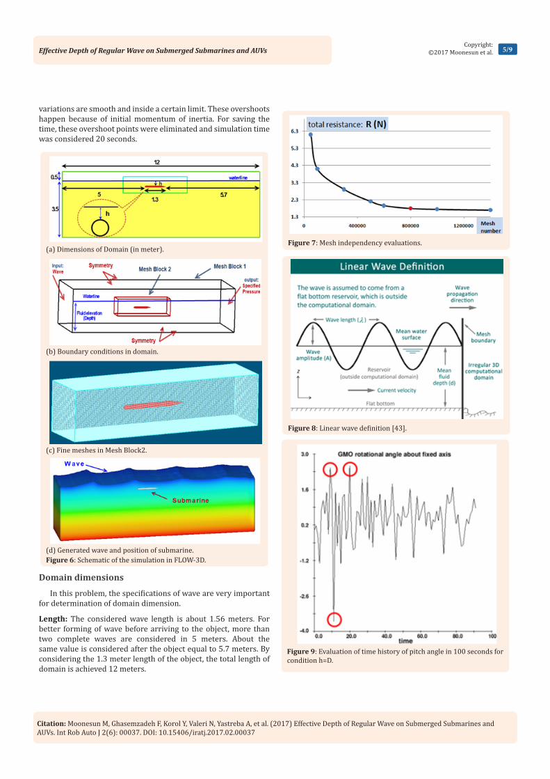
Domain and Boundary ConditionsThe general configurations and dimensions of domain are
shown in Figure 6. The length and width are 12 and 2.6meters. Depth is 4 meters (3.5 for draft and 0.5 for freeboard). The boundary conditions are: Input: wave, Output: Specified pressure and other sides are symmetry. The model is situated in different depths of “h” according to Figure 6a. There are two mesh block: one block for the total domain with coarse meshes and other block for fine meshes around the object body. The accuracy of the shape of the body depends upon the fine meshes (Figure 6b & 6c). For producing the wave, the input boundary condition is “Wave”. Flow-3D can produce regular and irregular waves. The produced wave and the situation of the object under the waves are shown
Figure 2: Values of Y+ along the body.
Figure 3: General configuration of the model Persia-110.

Citation: Moonesun M, Ghasemzadeh F, Korol Y, Valeri N, Yastreba A, et al. (2017) Effective Depth of Regular Wave on Submerged Submarines and AUVs. Int Rob Auto J 2(6): 00037. DOI: 10.15406/iratj.2017.02.00037
Effective Depth of Regular Wave on Submerged Submarines and AUVs 4/9Copyright:
©2017 Moonesun et al.
in Figure 6d. The reason of selecting each parameter is mentioned below.
Meshes
As mentioned above, there are two meshing block. The dimensions of mesh block2 are: 4*1*1 meters. By changing the location of the model, the situation of the mesh block 2 has been changed. For selecting the proper mesh numbers and mesh independency evaluation, several mesh numbers were analyzed (Figure 7). This diagram shows that for mesh numbers after 500.000 the variation is very little and after 800.000 remains almost constant. Therefore in all conditions of analyses in this study, the mesh number considered 800.000 which are 300.000 for mesh block1 and 500.000 for mesh block 2. Therefore mesh block 2 contains fine meshes around the object. Generally it should be notified that in wave problem, it doesn’t need for very fine meshes for modeling the boundary layer because the frictional forces are very small compare to the wave pressure forces. All meshes are hexahedral and without skew. Aspect ratio is 1, expansion factor between mesh block 1 and 2 equals to 2 and inside every block is 1. Mesh planes are coincided in the adjacent meshes.
Wave modeling
The defined Input boundary condition is a regular wave. General definitions of regular wave are represented in Figure 8. Here these parameters are defined in Flow-3D: wave amplitude 0.18 meters, wave period 1 second and mean fluid depth (according to the depth of domain) is 3.5 meters and current velocities are regarded zero. Based on these definitions, deep water condition is compatible because d/λ>0.5. For deep waters according to the formula of λ=1.56T2the wave length is 1.56 meters. Wave speed according to C=1.25 λ is 1.56m/s. The orbital radius of wave articles path(R) according to this formula is depended on the distance from water surface (h): R= A.e-kh and k=2π/λ. The variations of article radius versus depth were shown in Figure 1 and here can be stated as:
Figure 4a: Marine laboratory of Admiral Makarov University.
Figure 4b: Model Persia-110.Figure 4: Towing tank and model.
Figure 5: Comparison of the results of the experiment and CFD method.(a) Test in the surface draft of 7 cm and speed of 1 m/s (b) CFD modeling in the same conditions of experiment
a. At the water surface, h=0 and R=A which means at the surface, the radius of orbital motion of articles equals to wave amplitude.
b. At h=λ/2, there is R=0.043A.
c. At h=λ, there is R=0.002A. It is obvious that at the depth equal to λ/2, the circle radius is only 4% of the surface value and at the depth equal toλ, it is only 0.2% of the initial value at the
surface. Therefore at the depths more than λ/2 the wave will be damped out.
Simulation time
For selecting the proper simulation time, the time history of variation of pitch angle was studied in 100 seconds (Figure 9). This diagram shows that there are two overshoot points (maximum and minimum) and except these values, other
Citation: Moonesun M, Ghasemzadeh F, Korol Y, Valeri N, Yastreba A, et al. (2017) Effective Depth of Regular Wave on Submerged Submarines and AUVs. Int Rob Auto J 2(6): 00037. DOI: 10.15406/iratj.2017.02.00037
Effective Depth of Regular Wave on Submerged Submarines and AUVs 5/9Copyright:
©2017 Moonesun et al.
variations are smooth and inside a certain limit. These overshoots happen because of initial momentum of inertia. For saving the time, these overshoot points were eliminated and simulation time was considered 20 seconds.
Domain dimensions
In this problem, the specifications of wave are very important for determination of domain dimension.
Length: The considered wave length is about 1.56 meters. For better forming of wave before arriving to the object, more than two complete waves are considered in 5 meters. About the same value is considered after the object equal to 5.7 meters. By considering the 1.3 meter length of the object, the total length of domain is achieved 12 meters.
(a) Dimensions of Domain (in meter).
(b) Boundary conditions in domain.
(c) Fine meshes in Mesh Block2.
(d) Generated wave and position of submarine.Figure 6: Schematic of the simulation in FLOW-3D.
Figure 7: Mesh independency evaluations.
Figure 8: Linear wave definition [43].
Figure 9: Evaluation of time history of pitch angle in 100 seconds for condition h=D.

Citation: Moonesun M, Ghasemzadeh F, Korol Y, Valeri N, Yastreba A, et al. (2017) Effective Depth of Regular Wave on Submerged Submarines and AUVs. Int Rob Auto J 2(6): 00037. DOI: 10.15406/iratj.2017.02.00037
Effective Depth of Regular Wave on Submerged Submarines and AUVs 6/9Copyright:
©2017 Moonesun et al.
Breadth: The considered breadth is equal to object length (L=1.3m) to each side and the total breadth is 2L.
Breadth: As mentioned above, the wave base is approximately equal to λ/2. This study aims to evaluate the wave effects on the
submarine at the depth of 2λ. For avoiding the bottom effects, the draft of domain is considered 3.5 meters. The wave amplitude (A) is 0.18 meter, thus the freeboard above water level is considered 0.5 meter. Therefore the depth of domain is considered 4 meters. Settings of simulation are abstracted in Table 2.
Table 2: Settings of simulation.
Elements Boundary Conditions Descriptions
Conditionswith free surface and linear wave - domain
with inlet, outlet and symmetry - without heat transfer- without current velocity
Dimensions L*B*D=12*2.6*4m- draft 3.5m
Domain Cubic Grid
structured grid- hexahedral cells-without skew- two mesh block- more fine meshes in mesh block
2 around the object- Mesh number of 800.000, aspect ratio 1, expansion factor between blocks 2
and inside blocks 1. Y+=15~30
Settings Simulation time: 20 sec- Time step=0.005-0.013sec
Fluid -Incompressible fluid (fresh water)-
tempreture:20 deg- ρ=999.841 kg/m3- turbulent modeling: Standard k-ε
Object GMO Submarine, length:1.3m, Diameter:0.1, 1DOF free to pitch angle
Input Inlet Linear wave, wave amplitude 0.18 m, wave period 1sec, mean fluid depth 3.5m
Output Outlet Specified pressure (Specified fluid level: 3.5m)
Symmetry Symmetry In 4 faces
Initial conditions Fluid level: 3.5m
Considered Conditions for AnalysesFor studying the wave effects on the submarine, several depths
for submarine situation (h) are considered according to Figure 6a and Table 3.
Results and Discussion
Method of Extracting the Results
According to the diagram of Figure 9, there is a disordered and irregular variation of pith angle versus time. Usually in sea keeping studies, Root Mean Square (RMS) analysis is used. Therefore, here the RMS value of pitch angle is calculated in every depth, after eliminating the overshoot points. RMS is calculated as Eqn.9:
2 2 21 2 ... nRMS
nθ θ θ+ + +
= (9)
Results
The time history of pith angle in 12 conditions is analyzed. Figure 10 shows two samples of time history for h=0.1 and
0.35 meter. Table 3 represents the results for each depth. The percentage of decrease in last column is based on comparison to h=0 therefore; average= ( )( )*
0 0/ 100ih h h− . It should be notified that the static pitch angle of this submarine is 0.34 degree.
Discussion and Analysis
It is obvious that by increasing in the depth, the wave effect decreases and pitch angle approaches to static trim angle. The last column of Table 4 can smoothly describe the percentages of reduction in pitch angle. In depth of 0.03λ there is 33% reduction and in depth of 0.06λ there is 51% reduction. Intense gradient of pitch angle will be continued until the depth of 0.09λ which experiences 59% reduction. After this depth, there is a gentle variation. Values of RMS at the depths ofλ, 1.5λ and 2λ are equal to static trim angle which meant no effect of waves on the submarine. Almost around the depth of λ/2 the wave effect is negligible. The reason of this phenomenon is based on the principle of “wave base” which described in Introduction. It means that if a submarine dive to the depth more than λ/2, doesn’t experience the wave effects. For long swell waves, the value of λ/2 may be

Citation: Moonesun M, Ghasemzadeh F, Korol Y, Valeri N, Yastreba A, et al. (2017) Effective Depth of Regular Wave on Submerged Submarines and AUVs. Int Rob Auto J 2(6): 00037. DOI: 10.15406/iratj.2017.02.00037
Effective Depth of Regular Wave on Submerged Submarines and AUVs 7/9Copyright:
©2017 Moonesun et al.
more than the collapse depth of the submarine and be impossible. In this condition, if submarine dives to the depth about 0.1λ, it can avoid the 60% of motions and shakes. For instance, in a swell wave (which is very similar to regular waves) with a period of 15 seconds, the wave length is 351 meters. The half wave length is about 175 meters which may be dangerous depth for a submarine and it can be catastrophic. Despite that, if submarine dives to the depth of 0.1λ equal to about 35 meters, can navigate in very calm and more stable conditions.
Table 3: Considered conditions for analyses.
Submarine Depth (m) Description (Equivalent to)
1 0 Body tangent to free surface
2 0.05 Rs (or) 0.03l
3 0.1 Ds (or) 0.06l
4 0.15 1.5Ds (or) 0.09l
5 0.25 2.5Ds (or) 0.16l
6 0.35 3.5Ds (or) 0.22l
7 0.55 5.5Ds (or) 0.35l
8 0.75 7.5Ds (or) 0.48l
9 0.95 9.5Ds (or) 0.61l
10 1.6 ≅λ
11 2.4 ≅ 1.5λ
12 3 ≅ 3λ
Table 4: RMS values for considered conditions.
Depth (m) Depth (l) RMS (degree) Percentage of Decrease (%)
1 0 0 3.43 0
2 0.05 0.03 2.29 33
3 0.1 0.06 1.67 51
4 0.15 0.09 1.42 59
5 0.25 0.16 1.38 60
6 0.35 0.22 1.22 64
7 0.55 0.35 1 71
8 0.75 0.48 0.82 76
9 0.95 0.61 0.44 87
10 1.6 1 0.1 97
11 2.4 1.5 0.03 99
12 3 2 0 100
ConclusionIn conclusion, the results could be abstracted in the Figure
11 which fairly shows the gradient of motions versus depth of submergence. Depth of λ/2 could be considered as the absolutely calm depth but the depth of 0.1λ could be recommended as an operational safe and approximately calm depth for submarines.
(a) h=0.1 , RMS=1.67 deg.
(b) h=0.35 , RMS=1.22 deg.Figure 10: Time history of pith angle.
Figure 11: Gradient of RMS pitch versus submergence.
Citation: Moonesun M, Ghasemzadeh F, Korol Y, Valeri N, Yastreba A, et al. (2017) Effective Depth of Regular Wave on Submerged Submarines and AUVs. Int Rob Auto J 2(6): 00037. DOI: 10.15406/iratj.2017.02.00037
Effective Depth of Regular Wave on Submerged Submarines and AUVs 8/9Copyright:
©2017 Moonesun et al.
Nomenclature
λ Wave length (m)
θ Pitch angle (degree)
δ thickness of boundary layer (m)
δ' thickness of laminar sub layer (m)
τw Wall shear stress (N/m2)
ν kinematic viscosity (m2/s) equals to 0.000001 for water at 20oC
A Wave amplitude (m)
AUV Autonomous Underwater Vehicle
Cf skin-friction coefficient
CFD Computational Fluid Dynamics
d Depth of water (m)
Ds Diameter of submarine body
DOF Degree Of Freedom
GMO General Moving Object
h Distance from top of the object (submarine) to the water surface (m)
IHSS Iranian Hydrodynamic Series of Submarines
L Length of object (submarine)
R orbital radius of wave articles path (m)
Re Reynolds Number (-)
Rs Radius of submarine body
RMS Root Mean Square
VOF Volume Of Fluid
U Speed between submarine and fluid (m/s)
u* friction velocity (m/s)
Y wall distance (m)
Y+ non-dimensional wall distance (-)
References1. Thurman, Harold V, Trujillo, Alan P (2001) Essentials of
Oceanography. (5th edn), Prentice Hall, USA, pp. 240-243.
2. Dean, WR (1948) On the Reflexion of Surface Waves by a Submerged Circular Cylinder. Proc Camb Phil Soc 44(4): 483-491.
3. Ursell, F (1949) Surface Waves in the Presence of a Submerged Circular Cylinder, I and II. Proc Camb Phil Soc 46:141-158.
4. Ogilvie, TF (1963) First- and Second-Order Forces on a Cylinder Submerged Under a Free Surface. J Fluid Mech 16(3): 451-472.
5. Chaplin JR (1984) Nonlinear Forces on a Horizontal Cylinder Beneath Waves. J Fluid Mech 147: 449-464.
6. Etienne Guerber, Michel Benoit, Stéphan T. Grilli, Clément Buvat (2010) Modeling of Fully Nonlinear Wave Interactions with Moving Submerged Structures. Proceedings of the Twentieth (2010) International Offshore and Polar Engineering Conference, China, pp. 529-536.
7. Wu, GX (1993) Hydrodynamic Forces on a Submerged Circular Cylinder Undergoing Large-amplitude Motion. J Fluid Mech 254(1): 41-58.
8. Evans, DV, Jeffrey, DC, Salter, SH, Taylor, JRM (1979) Submerged Cylinder Wave Energy Device: theory and experiment. Applied Ocean Research 1(1): 3-12.
9. D Dessi, A Carcaterra, G Diodati (2004) Experimental investigation versus numerical simulation of the dynamic response of a moored floating structure to waves. Proceedings of the Institution of Mechanical Engineers, Part M: Journal of Engineering for the Maritime Environment 218(3): 153-165.
10. Salter SH, Taylor JRM, Caldwell NJ (2002) Power conversion mechanisms for wave energy. Proceedings of the Institution of Mechanical Engineers, Part M: Journal of Engineering for the Maritime Environment 216(1): 1-27.
11. Joubert PN (2004) Some aspects of submarine design: part 1: Hydrodynamics. Australian Department of Defence, Australia, p. 1-70.
12. Joubert PN (2004) Some aspects of submarine design: part 2: Shape of a Submarine 2026. Australian Department of Defence, Australia, p. 1-33.
13. Moonesun M, Korol Y, Dalayeli H (2015) CFD Analysis on the Bare Hull Form of Submarines for Minimizing the Resistance. International Journal of Maritime Technology 3 (2): 1-16.
14. Renilson M (2015) Submarine Hydrodynamics, Springer, p. 45-89.
15. D Neulist (2011) Experimental Investigation into the Hydrodynamic Characteristics of a Submarine Operating Near the Free Surface, Australian Maritime College, Australia.
16. Dawson E, Anderson B, Steel SV, Renilson M, Ranmuthugala D (2011) An experimental investigation into the effects of near surface operation on the wave making resistance of SSK type submarine. Australian Maritime College, Australia.
17. S Wilson-Haffenden, Renilson M, Ranmuthugala D, Dawson E (2009) An Investigation into the Wave Making Resistance of a Submarine Travelling Below the Free Surface. Australian Maritime College, Australia.
18. S Van Steel (2010) Investigation into the Effect of Wave Making on a Submarine Approaching the Free Surface. Australian Maritime College, Australia.
19. Polish C, Ranmuthugala D, Duffy J, Renilson M (2011) Characterisation of near surface effects acting on an underwater vehicle within the vertical plane. Australian Maritime College, Australia.
20. Alvarez A, Bertram V, Gualdesi L (2009) Hull hydrodynamic optimization of autonomous underwater vehicles operating at snorkeling depth, Ocean Engineering 36: 105-112.
21. Shiyang Wang, Lixin Cui, Chao Wang, Sheng Huang, Resistance performance of submarine under different traveling stations, Harbin Engineering University Harbin, China.
22. Moonesun M, Korol Minimum YM (2015) Immersion Depth for Eliminating Free Surface Effect on Submerged Submarine Resistance. Turkish Journal of Engineering, Science and Technology (TUJEST) 3(1): 36-46.
23. Fossen TI (1999) Guidance and Control of Ocean Vehicles, John Wiley and Sons Ltd, UK, pp. 1-494.
24. Fossen TI (2011) Handbook of Marine Craft Hydrodynamics and Motion Control, John Wiley and Sons Ltd, UK.
Citation: Moonesun M, Ghasemzadeh F, Korol Y, Valeri N, Yastreba A, et al. (2017) Effective Depth of Regular Wave on Submerged Submarines and AUVs. Int Rob Auto J 2(6): 00037. DOI: 10.15406/iratj.2017.02.00037
Effective Depth of Regular Wave on Submerged Submarines and AUVs 9/9Copyright:
©2017 Moonesun et al.
25. Feldman J (1979) Revised standard submarine equations of motion, Naval Ship Research and Development Centre. Tech Rep DTNSRDC-SPD-0393-09, p. 1-31.
26. Spencer JB Stability and Control of Submarines, Parts I-IV, Reprint of the Royal Naval Scientific Service 23(3): 187-345.
27. Gertler M, Hagen GR (1967) Standard Equations of Motion for Submarine Simulation, Naval Ship Research and Development Centre, Tech Rep RNSRDC2510, p. 1-42.
28. Richards RJ, Stoten DP (1981) Depth Control of a Submersible Vehicle, Int Shipbuilding Progress 81: 30-39.
29. Grimble M, Gvan der Molen, Liceaga-Castro E (1993) Submarine Depth and Pitch Control, IEEE Conf Contr Appl Vancouver, Canada.
30. Daniel CJ, Richards RJ (1982) A Multivariable Controller for Depth Control of a Submersible Vehicle, Inst of Meas and Cont Conf on Application of Multivariable System.
31. Yangling Hao, Donghui Shen, ZhilanXiong (2004) Design of Submarine Near Surface Depth Controller. IEEE 5th World Congress on Intelligent Control and Automation, China, pp. 4530-4533.
32. Griffin MJ (2002) Numerical Prediction of the Maneuvering Characteristics of Submarines Operating Near the Free Surface. MIT, USA.
33. Johnston GW, Foster SP (1991) Frequency Domain Prediction of Submarine Motion in Waves (SUBMO). National Defence Research and Development, Canada.
34. Rhee K, Choi J, Lee S (2008) Mathematical model of wave forces for the depth control of a submerged body near the free surface. International offshore and polar engineering conference, Canada, p. 1-8.
35. Wang X, Sun Y, Hong W (2008) Catastrophe of submarine near surface motion, IEEE 1-4244-2386-6, China.
36. Ni SY, ZhangL, Dai YS Hydrodynamic Forces on a Moving Submerged Body in Waves. International Shipbuilding Progress, 41: 95-111.
37. Booth TB (1983) Optimal depth control of an underwater vehicle under a seaway. RINA Symp, Naval Submarines, London, p. 17-19.
38. Lisegaga Castro E, Molen M (1995) Submarine H/sup /spl infin// depth control under wave disturbances, IEEE Transactions on Control Systems Technology 3(3): 338-346.
39. Musker AJ, Loader PR, Butcher MC (1988) Simulation of a submarine under waves. International shipbuilding progress 35(404): 389-410.
40. Dogan PP (1967) Optimum stabilization of a near surface submarine in random seas, Cambridge, MIT, USA.
41. João LD Dantas, Jose J da Cruz, and Ettore A de Barros (2014) Study of autonomous underwater vehicle wave disturbance rejection in the diving plane. Proceedings of the Institution of Mechanical Engineers, Part M: Journal of Engineering for the Maritime Environment 228(2): 122-135.
42. Henry ChJ, Milton M, Kaplan M (1961) Wave forces on Submerged Bodies, Davidson Laboratory, USA, p, 1-86.
43. Moyuki YOKOKAWA, Tadashi ENOMOTO, Takashi YAMAZAKI, Kazuya KUWAHARA, Masaru FURUSHOU, et al. (2009) Analysis on Viscous Flow of VAD Silica Glass During Heat Forming. INDUSTRIAL MATERIALS, p. 1-5.
44. C Baker (2004) Estimating Drag Forces on Submarine Hulls. Defence research and development, Canada, pp. 1-152.