effect of partial saturation of bonded neo magnet on the ... · partial saturation on the motor...
TRANSCRIPT

Effect of partial saturation of bonded neo magnet on the automotive accessorymotorNimitkumar K. Sheth and Raghu C. S. Babu Angara
Citation: AIP Advances 7, 056611 (2017); doi: 10.1063/1.4973496View online: http://dx.doi.org/10.1063/1.4973496View Table of Contents: http://aip.scitation.org/toc/adv/7/5Published by the American Institute of Physics

AIP ADVANCES 7, 056611 (2017)
Effect of partial saturation of bonded neo magneton the automotive accessory motor
Nimitkumar K. Shetha and Raghu C. S. Babu AngaraR&D, Neo Performance Materials Pte Ltd, Singapore 117525, Singapore
(Presented 4 November 2016; received 23 September 2016; accepted 10 October 2016;published online 27 December 2016)
In this paper the effects of using a partially magnetized bonded neo (NdFeB) mag-net in an automotive accessory motor are presented. The potential reason for partialsaturation of the bonded neo magnet is explained and a simple method to ensuresaturation of the magnet is discussed. A magnetizing fixture design using the 2-D Finite element analysis (FEA) is presented. The motor performance at variousmagnet saturation levels has been estimated using the 2-D FEA. Details of thethermal demagnetization test adopted by the automotive industry is also discussedand results of the motor performance for four saturation levels are detailed. Theseresults indicate that the effect of demagnetization is more adverse in a motor withpartially saturated magnets. © 2016 Author(s). All article content, except where oth-erwise noted, is licensed under a Creative Commons Attribution (CC BY) license(http://creativecommons.org/licenses/by/4.0/). [http://dx.doi.org/10.1063/1.4973496]
I. INTRODUCTION
Bonded neo magnet based motors are fast gaining popularity in automotive accessory applica-tions as they offer substantial weight/size reduction and efficiency improvement over the traditionalferrite based motors. The weight reduction and efficiency improvement helps in achieving the strin-gent fuel efficiency improvement and CO2 emission reduction targets. The partial demagnetizationor the irreversible flux loss at high temperature and/or at load is the major concerns with the perma-nent magnet motors.1 Different magnet needs different energy level to achieve full saturation, andhence their full potential. Figure 1 show the typical magnetizing fields required to saturate isotropicbonded neo and ferrite magnets. It is evident from Fig. 1 that isotropic bonded neo magnets needa stronger field for saturation than the ferrite magnets. For the ferrite based motor the verificationof post assembly magnetization is proposed in literature.2 Bonded neo magnets are isotropic innature compared to the anisotropic nature of ferrite magnets and hence need special attention forthe magnetizing fixture design to achieve the desired magnetization profile and full saturation. Fer-rite magnets have been the traditional choice for the automotive accessory motors, leading to thepossibility that during the magnetization of bonded neo magnet one uses the magnetizing energyneeded to saturate the ferrite magnet by mistake. In such a case, application of insufficient mag-netizing field and/or inappropriate magnetizing fixture will lead to a partially saturated bonded neomagnet.
In this paper, using two dimensional (2-D) finite element (FE) analysis, the effects of demag-netization on the performance of an automotive accessory motor with a partially saturated bondedneo magnet is presented in Section–II. A magnetization fixture designed for in-situ magnetizationof bonded neo magnet is also presented. In Section III, the motor demagnetization test followed byautomotive industry is discussed. Motor performance for different saturation level of bonded neomagnets before and after the demagnetization test is presented and the effect of partial saturation isquantified.
aAuthor to whom correspondence should be addressed. Electronic mail: [email protected].
2158-3226/2017/7(5)/056611/7 7, 056611-1 © Author(s) 2016

056611-2 N. K. Sheth and R. C. S. B. Angara AIP Advances 7, 056611 (2017)
FIG. 1. Saturation field for ferrite and bonded neo magnets.
II. FINITE ELEMENT (FE) ANALYSIS
An Isotropic bonded neo magnet needs to be fully saturated to utilize its complete potential. Asindicated in the previous section, the magnetization of bonded neo magnet requires special attentionto the fixture design and the total energy required for saturation. Table I gives the specificationsof the automotive accessory motor used for analysis. For the bonded neo magnet given in Table I,a magnetization fixture is designed using commercially available Opera Vector Fields 2-D FEAsoftware, for in-situ magnetization in which the magnet is inserted into the motor pole housingbefore magnetization.
A. Magnetization of magnet
To ensure full saturation of a permanent magnet, a saturation test needs to be performed duringthe magnetization of the magnet. In the saturation test the applied magnetizing energy is increasedin appropriate steps and the magnet flux per pole is measured after magnetization at each step.The magnet is considered saturated if the change in magnet flux per pole between consecutiveenergy steps is less than 2%. Figure 2 shows the cross section of the designed magnetizing fixture.Figure 3 shows the result of the saturation test on a typical bonded neo magnet. The generatedmagnetizing field is about 1 T when the applied energy is 560 J, which represents the energyrequired to fully saturate the ferrite magnet as seen from Fig. 1 or 60% saturation of bondedneo magnet as seen from Fig. 3. As Ferrite magnets are widely used in an automotive acces-sory application, the applied energy or saturation limit of 60% is considered as lower limit in thisstudy.
The magnets are virtually magnetized for 60%, 80%, 90% and 100% or full saturation of thebonded neo magnets. The magnetized magnet data is imported in to the motor model shown inFig. 4 and the motor performance is simulated.3 Figure 5 shows the no-load air-gap flux distri-bution in the motor. The area under the curve is calculated using the trapezoidal rule for definiteintegral. Table II gives the calculated no-load air-gap flux integral for motors with different satura-
TABLE I. Specifications of the automotive accessory motor.
Parameter Value
Number of slots 10Number of poles 4Air gap 0.375 mmMotor outer diameter 30.5 mmMotor length 43 mmMagnet grade MQP 15-9HD-20178Magnet residual induction, Br 0.693 TMagnet coercivity, Hc 448 kA/m

056611-3 N. K. Sheth and R. C. S. B. Angara AIP Advances 7, 056611 (2017)
FIG. 2. Cross section of the magnetizing fixture for bonded neo magnets.
FIG. 3. Saturation test plot for a typical bonded neo magnet.
tion levels. From Table II it can be seen that the calculated no-load air-gap flux integral per polein the motor with 60% saturation magnet is 32% less compared to the motor with fully saturatedmagnet.
FIG. 4. Motor cross section for 2-D FE analysis.

056611-4 N. K. Sheth and R. C. S. B. Angara AIP Advances 7, 056611 (2017)
FIG. 5. Effect of magnet saturation level on the motor no-load air gap flux.
TABLE II. Comparison of air-gap flux integral before and after thermal demagnetization test.
Parameter 100% 90% 80% 60%
Before demagnetization (T-rad) 3.06 2.62 2.36 2.07After demagnetization (T-rad) 2.98 2.55 2.27 1.96
B. Demagnetization analysis
Figure 6 shows the first and second quadrant major and minor magnetization curves, the loadlines and operating points of the motor at no-load and stall conditions for a typical bonded neo magnetmotor at room and high temperatures. At a given operating temperature, the motor operates alongthe major curve when the magnet is fully saturated and if the magnet is partially saturated then theoperating point shifts to the minor curve at the same temperature.4
In Fig. 6, point ‘a’ represents the no-load operating point at room temperature in a motorwith fully saturated magnet. When the motor temperature increases the operating point shifts topoint ‘b’ along the same load line. As the motor is loaded, the load line moves along the negativeY-axis with the same slope by a distance proportional to the applied load, resulting in the oper-ating point moving from point ‘b’ towards point ‘c’. Under stall conditions, the slope of the loadline decreases due to low permeance coefficient resulting in operation of motor at point ‘c’. When
FIG. 6. Motor operating point at different magnet temperatures and loads.

056611-5 N. K. Sheth and R. C. S. B. Angara AIP Advances 7, 056611 (2017)
FIG. 7. Comparison of air-gap flux at no-load and after thermal demagnetization test in motors with 100% and 60% saturatedbonded neo magnet.
a motor has partially saturated magnet the no-load operating point at room temperature starts at‘a′’ and moves to point ‘b′’ at high temperature. Under load conditions at high temperature, theoperating point shifts along line ‘b′c′’. The increased load or stall torque condition may result inshifting of the load line such that the operating point falls below knee point resulting in irreversibledemagnetization.
The typical demagnetization test for the automotive accessory motors is performed with themotor being subjected to an elevated temperature of 100◦C to 120◦C. To understand the effect ofpartial saturation on the motor performance, the same motor models have been analyzed for themagnet temperature of 120◦C. Figure 7 shows the air-gap flux distribution when a demagnetizationfield is applied in a motor with a fully saturated magnet and a motor with 60% saturated magnet.Table II gives the air-gap flux integral after demagnetization in the motors with different levels ofmagnet saturation. From this table, it is observed that the air-gap flux integral is only reduces by 2.6%for motor with fully saturated magnet compared to 5% in a motor with 60% saturated magnet.
Figure 8 shows the magnet flux density and flux lines in the magnet after applying the demagne-tization field while magnet exposed to 120◦C for both the fully saturated and 60% saturated magnets.It is observed from Fig. 8, that the demagnetization under load is very severe in a partially satu-rated magnet and is prominent near transition zone between two magnetic poles.5 The magneticdomains in the transition zones are tangential to the magnet’s orientation, the energy required todemagnetize the region near the transition zone is less, leading to severe demagnetization near tran-sition zone. In the analyzed motor the demagnetization effect is the maximum for 60% saturatedmagnet.
FIG. 8. Flux distribution in magnet at 120◦C magnet temperature and stall current.
056611-6 N. K. Sheth and R. C. S. B. Angara AIP Advances 7, 056611 (2017)
III. MOTOR EVALUATION
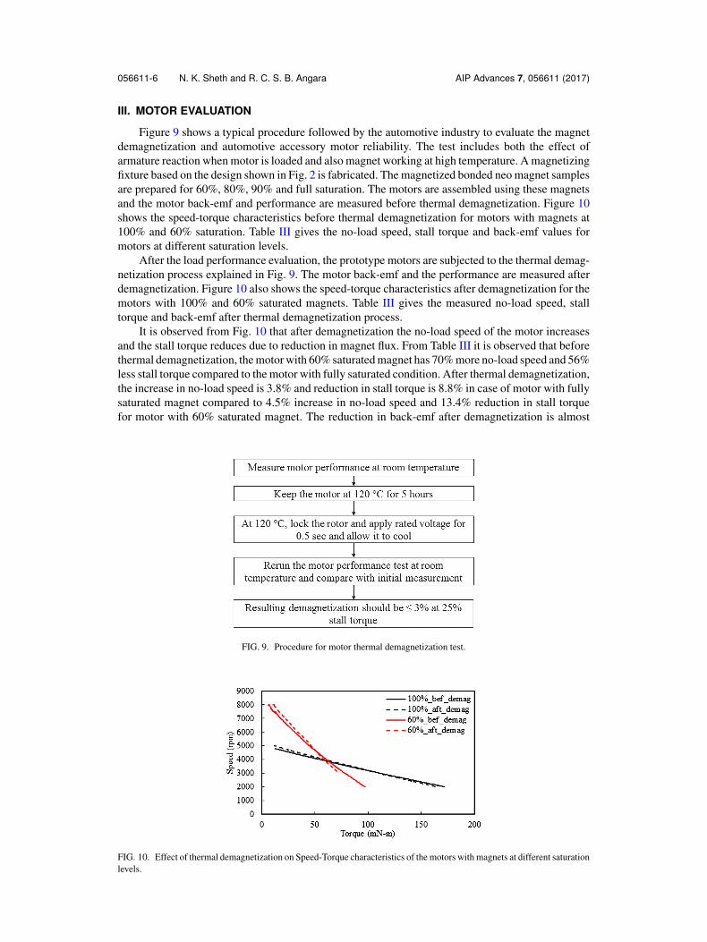
Figure 9 shows a typical procedure followed by the automotive industry to evaluate the magnetdemagnetization and automotive accessory motor reliability. The test includes both the effect ofarmature reaction when motor is loaded and also magnet working at high temperature. A magnetizingfixture based on the design shown in Fig. 2 is fabricated. The magnetized bonded neo magnet samplesare prepared for 60%, 80%, 90% and full saturation. The motors are assembled using these magnetsand the motor back-emf and performance are measured before thermal demagnetization. Figure 10shows the speed-torque characteristics before thermal demagnetization for motors with magnets at100% and 60% saturation. Table III gives the no-load speed, stall torque and back-emf values formotors at different saturation levels.
After the load performance evaluation, the prototype motors are subjected to the thermal demag-netization process explained in Fig. 9. The motor back-emf and the performance are measured afterdemagnetization. Figure 10 also shows the speed-torque characteristics after demagnetization for themotors with 100% and 60% saturated magnets. Table III gives the measured no-load speed, stalltorque and back-emf after thermal demagnetization process.
It is observed from Fig. 10 that after demagnetization the no-load speed of the motor increasesand the stall torque reduces due to reduction in magnet flux. From Table III it is observed that beforethermal demagnetization, the motor with 60% saturated magnet has 70% more no-load speed and 56%less stall torque compared to the motor with fully saturated condition. After thermal demagnetization,the increase in no-load speed is 3.8% and reduction in stall torque is 8.8% in case of motor with fullysaturated magnet compared to 4.5% increase in no-load speed and 13.4% reduction in stall torquefor motor with 60% saturated magnet. The reduction in back-emf after demagnetization is almost
FIG. 9. Procedure for motor thermal demagnetization test.
FIG. 10. Effect of thermal demagnetization on Speed-Torque characteristics of the motors with magnets at different saturationlevels.

056611-7 N. K. Sheth and R. C. S. B. Angara AIP Advances 7, 056611 (2017)
TABLE III. Comparison of motor performance before and after thermal demagnetization test.
Parameter 100% 90% 80% 60%
Back-emf before demagnetization (V) 8.3 7.7 6.6 4.4Back-emf after demagnetization (V) 8.3 7.3 6.2 4.1No-load speed before demagnetization (rpm) 4892 5446 6370 8340No-load speed after demagnetization (rpm) 5077 5758 6640 8717Stall torque before demagnetization (mN-m) 287 251 210 125Stall torque after demagnetization (mN-m) 262 227 193 109
negligible in case of motor with fully saturated magnet compared to 6.5% reduction for motor with60% saturated magnet.
From the motor performance evaluation results, it is evident that the partial saturation of themagnet will lead to severe magnet demagnetization and hence poor motor performance.
IV. CONCLUSION
In this paper the potential effects of using partially magnetized bonded neo magnet in an auto-motive accessory motor are presented. About 60% of the energy required to saturate a bonded neomagnet is sufficient to saturate a ferrite and hence the magnetization fixture and/or the magnetizationenergy needed to saturate ferrite magnet should not be applied to bonded neo magnetization as it willlead to partially saturated bonded neo magnet. The performance measured for automotive accessorymotors with different saturation levels indicate that after thermal demagnetization, the stall torque isreduced by 4.5% and no-load speed increased by 13.4% for the motor with 60% saturated magnetcompared to 3.8% increase in no-load speed and 8.8% reduction in stall torque when the magnet isfully saturated. To avoid the adverse effects of thermal demagnetization and to utilize the completepotential of the bonded neo magnet, full saturation of the magnet must be ensured.
1 K. C. Kim, K. Kim, H. J. Kim, and J. Lee, “Demagnetization analysis of permanent magnets according to rotor types ofinterior permanent magnet synchronous motor,” IEEE Transactions on Magnetics 45, 2799–2802 (2009).
2 K. W. Lee, J. Hong, S. B. Lee, and S. Lee, “Quality assurance testing for magnetization quality assessment of bldc motorsused in compressors,” IEEE Transaction on Industry Applications 46, 2452–2458 (2010).
3 Y. Zhilichev, “Analysis of permanent magnet demagnetization accounting for minor B-H curves,” IEEE Transaction onMagnetics 44, 4285–4288 (2008).
4 S. Ruoho, E. Dlala, and A. Arkkio, “Comparison of demagnetization models for finite-element analysis of permanent magnetsynchronous machines,” IEEE Transaction on Magnetics 43, 3964–3968 (2007).
5 G. Sawczuk and J. Junak, “Finite element analysis of permanent magnet synchronous motor considering magnetizationprocess,” International Conference on Electrical Machines and Systems 7–12 (2013).