effect of directly welded stringer-to-beam connections … 1.pdf · effect of directly welded...
TRANSCRIPT

1
EFFECT OF DIRECTLY WELDED STRINGER-TO-BEAM CONNECTIONS ON THE ANALYSIS AND DESIGN OF MODULAR STEEL BUILDING FLOORS
C.D. Annan1, M.A. Youssef 2, *, M.H. El-Naggar3 1 Ph.D. Candidate, 2 Assistant Professor, 3 Professor
Department of Civil and Environmental Engineering, The University of Western Ontario, London, ON
Abstract
Modular Steel Buildings (MSBs) are fast evolving as an effective alternative to conventional on-
site steel construction. An explanation of the concept of modular construction and a summary of
its commonly used construction details are given in this paper. This is expected to increase
awareness of this unique system among structural engineers and allow researchers to study its
critical elements. The paper also focuses on a typical floor system, which is conventionally
achieved in MSBs by welding the webs of the stringers directly to the webs of the floor beams. A
typical modular steel floor framing is designed as in-current practice using conventional
methods. The floor is then modeled using the finite element method and analyzed under the
effect of dead and live service loads. This allowed assessment of the effect of direct welding
between the stringers and the floor beams on the analysis and design of floor beams, stringers,
and the welded connections. The results revealed that consideration of the true behavior of the
directly welded connections leads to distribution of forces and moments that are different from
conventional steel buildings. A simplified model is proposed. The finite element results were
used to develop regression functions that describe the model. The proposed model can practically
predict the actual forces and moments and thus lead to a reliable design of modular steel framing.
Keywords: Modular steel buildings, floor framing, directly welded connection, finite element analysis, analytical model, regression function.
* Corresponding author. Tel.: +1 519 661-2111 Ext. 88661; Fax: +1 519 661-3779. E-mail address: [email protected] (M.A. Youssef)

2
1.0 Introduction
Over the years, there has been an ever-growing demand by construction industry clients
for speedy, flexible, and cost-effective products. This demand, coupled with highly dynamic
market forces, has made traditional on-site building construction processes very complex. The
modular construction technique is fast evolving as an effective alternative. The technique is
widely used in North America, Japan, and in parts of Europe. It involves the design of structures
to be built and finished at one location and be transported to and used at another. The main
advantage of modular construction technique is largely speed of construction, while combining
the design flexibility of traditional methods with the quality of controlled manufacturing.
The concept of modular design has been adopted by many engineering industries. In the
civil engineering building industry, the term is used for the factory construction of pre-
engineered building units, delivered to site and assembled as large volumetric components or as
substantial elements of a building. The volumetric concept of modular construction may be
similar to temporary or relocatable buildings but differs greatly in terms of quality, structural
design and general performance criteria. The collection of discrete modular units usually forms a
self-supporting structure in its own right or, for multi-storey buildings, may rely on an
independent structural framework. The modular units are often fully fitted, complete with floors,
lighting, plumbing, heating, etc. before they are delivered to site for installation.
Applications of modular construction within the civil engineering sector are found mainly
in general building construction, particularly apartment buildings, hotels, student residences,
hospitals, offices, fast-food outlets and correctional facilities where units are repetitive. Rapid
construction and installation has been the major driving force behind the modular building
industry, since savings in time can be directly transformed to business related benefits. For

3
example, it has been suggested that on-site construction times in hotels and fast-food restaurants
could be reduced by over 60% with the adoption of modular construction (Lawson et. al., 1999).
Such a huge potential savings in time and costs may be due to such factors as allowing
simultaneous site preparation and module construction, and reduced vulnerability to weather
conditions that may slow or stop traditional construction. Other related benefits include the
avoidance of disruption and loss of operation during extension works in existing or neighboring
facilities such as hotels, and also the achievement of high quality control under off-site
manufacturing conditions, including pre-installation checks. Clearly, however, economy of scale
of production is an important factor that has to be considered against these benefits. In other
words, it may be more expensive to use modular construction, instead of traditional construction,
for an irregular building or non-repetitive units.
Light steel framing has been widely used in modular construction, perhaps due to its
efficient utilization of material and its ability to integrate lighter weight materials into
sophisticated manufacturing process. Other benefits of the use of light steel framing in the
context of modular construction may include its lightness during lifting and transportation and
the high level of acoustic and thermal insulation that can be provided on the framing. The Steel
Construction Institute (SCI) of the United Kingdom has conducted some studies on performance
specification for modular construction using this material (Lawson et al., 1999). The limitations
of the use of light steel framing in modular buildings are evident in its range of applications. For
heavily loaded structures, structural steel shapes, such as I-sections, are more useful and
efficient. The use of such sections in modular building construction is what has been referred to,
in this paper, as MSBs.

4
Modular building techniques are not new in North America, with several manufacturing
plants spread across the United States and Canada. The Modular Building Institute (MBI) in the
United States and the Modular Building Association of British Columbia (MBABC) in Canada,
are two major institutions committed to the promotion of continued development of the modular
building industry in North America. A number of construction organizations under these
institutions have undertaken large-scale modular building construction projects including a 150
bedroom hotel project (worth US$6.5 million) at the Quinault Beach resort in Washington which
achieved a 50% cut on traditional construction time (MBABC, 2000), a 790 bedroom permanent
residence facility (worth $40.8 million CDN) for the Collahausi copper mining project in Chile
(MBABC, 1997), and a four-storey modular steel building for SUNY Purchase College
Dormitory in New York (Murray Engineering, P.C., 2000).
To the best of the authors’ knowledge, this is the first technical paper explaining how
such structural steel shapes are being used by MSBs manufacturers. This is expected to pave way
for other researchers to study different aspects of the MSB technology. Another objective of this
paper is to study the effect of direct welding between the floor stringers and the floor beams in
MSB floor system on the analysis and design of the system.
The paper begins with a description of typical details of MSBs, including the floor
stringer-to-beam connections, drawing comparison with conventional steel buildings. A typical
MSB floor-system is designed using the Canadian steel design code (CISC, 1997). It is then
analyzed using the finite element (FE) method. A parametric study is conducted on some
geometric parameters likely to affect the response of the floor framing to further investigate its
behavior. The results of the FE analysis are used to reassess the capacities of the various
components of the floor system. A simplified analytical model is proposed to predict the forces

5
and moments in the modular steel floor framing in order to reliably design the various
components of the system.
2.0 Modular Steel Buildings
Structural steel shapes are used in the construction of durable and ‘heavily loaded’ MSB
structures. They have been typically used for one-to-six storey schools, hotels, correctional
facilities and dormitories. The modules are assembled in a manufacturing plant and this allows
excavation and foundation works to be carried out simultaneously with the building of the
modules. Moreover, fabricating the modules in a controlled indoor environment ensures higher
quality standards. Each module consists of a floor and a ceiling separated by a number of
columns. The floor framing is typically composed of two floor beams, a number of floor
stringers and a floor metal deck with concrete topping. Similarly, the ceiling framing includes
two ceiling beams and a number of ceiling stringers.
Figure 1 shows typical floor/ceiling steel framing of a four-storey MSB. It consists of six
modules, labeled M#1 to M#6. The floor beams (FB) or ceiling beams (CB) are oriented along
the building width and the floor stringers (FS) or ceiling stringers (CS) in each module are along
the building length. Horizontal and vertical connections of different modules are made onsite. A
typical horizontal connection (HC) is shown in section A-A of Figure 1. It usually involves field
bolting of clip angles, which are shop-welded to the floor beams. Section B-B of Figure 1 depicts
a typical vertical connection (VC). The section shows the base plates of the upper module
column field-welded to the cap plates of the lower module column.

6
Figure 2 shows sections of a typical floor arrangement. The second floor assembly
depicts floor arrangements of two modules of the second storey located side-by-side and ceiling
arrangements of two modules of the first storey. The assembly also shows sections of steel deck
(usually welded to the flange of the floor beam), concrete floor and the ceiling finishes. The first
floor assembly (bottom section) depicts floor arrangements of two side-by-side modules of the
first storey and their connection to the concrete footing.
Lateral stability of MSBs is achieved either by developing moment frames of the floor
beams, ceiling beams, floor stringers, ceiling stringers and columns within each module or by
adding diagonal braces as shown on Figure 1. Lateral loads are resisted in the shorter direction
by the external braced frame of modules M#1 and M#6 and in the longitudinal direction by the
external braced frame of modules M#2 and M#5. Within each floor, lateral loads are transferred
to the braced frame through the horizontal connections (HC). The total lateral load is then
transferred through the vertical connections (VC) to the foundation. The lateral response of
MSBs is a subject of an on-going study.
3.0 Floor stringer-to-beam connections
Significant differences exist between the methods of construction of MSBs and
conventional steel buildings. In MSBs, for example, the floor-system is typically designed as a
grid structure consisting of floor stringers and beams. Floor stringer-to-beam connections in
conventional construction are usually achieved using clip angles, which are shop welded to the
web of the floor beam and site bolted to the web of the floor stringer. In modular steel floor
framing, however, such connections are achieved in a controlled factory environment by direct

7
welding of the webs of the joining members. Floor stringers may be fully or partially connected
to floor beams using fillet welds.
The use of clip angles in conventional construction results in transferring reactions from
the ends of the stringers to the floor beams through shear action, while allowing for partial
rotation. This rotation is accommodated by the movement of clip angles within the clearance
around the bolts and by the elastic and inelastic deformations occurring in the bolts, clip angles,
and stringer beams. This enables redistribution of any negative moment that might develop at
these connections. To analyze this type of connections, material nonlinearities for the clip angles,
bolts, and stringer beam need to be considered. Also, the contact behavior between the bolts, the
clip angles, and the floor beams must be modeled. Lipson (1968) conducted an experimental
study to evaluate the static behavior of single web angle connections. It was reported that these
connections exhibited nonlinear moment-rotation behavior at early stages of loading which is
expected to allow redistribution of beam moments. Al-Emrani and Kliger (2003) conducted a
finite element analysis to study the behavior of double angle stringer-to-floor beam connections
in riveted railway bridges. The stringers were modeled using shell elements and solid elements
were used to model the angles and the rivets in the connection. The contact between the back-
face of the leg of the connection angle and the web of the floor beam was modeled using linear
quadratic rigid elements. The Coulomb-friction model was used to characterize the interface
conditions at all the contact surfaces. They concluded that a connection moment might develop
in these connections, which make such connections vulnerable to fatigue damage.
In the case of directly welded connections commonly used in floor systems of MSBs, the
behavior is different. The weld is known to have much higher stiffness when compared to the
bolted clip angle connection. Thus, it would allow for limited deformations before exhibiting a

8
brittle failure mode (Faella et al., 2000). Rotation in these connections would occur only as a
result of a plastic hinge forming at the ends of the stringers when the negative moment exceeds
the yielding moment. It is expected, however, in such directly welded floor stringer-to-beam
connection in MSBs that the positive moment will be much higher than the negative end
moments (hogging moments). Hence, redistribution of end moments will not occur and such
hogging moments need to be accounted for in design should they develop. This, combined with
the fact that welds have very limited deformation capacity, makes a linear elastic finite element
analysis adequate to evaluate the effect of hogging moments likely to develop from the direct
welding in MSB floor system.
4.0 Design of Modular Grid Structure
A four-storey modular dormitory is considered in this study. Each floor is made up of six
identical modules consisting of bedrooms and a corridor. The modular steel floor-system adopted
in the study is designed as a grid structure consisting of floor stringers and beams. The floor
framing consists of two floor beams supporting eleven floor stringers as shown in Figure 3. Each
floor stringer has a span of 3600 mm and the total length of each floor beam is 16500 mm. The
stringers are labeled as SB1 to SB6, with the module symmetric about SB6. The dead load (DL)
is composed of the weights of the concrete floor (100 mm thick), an all round metal curtain wall
system and insulation, steel deck and members’ own weights. A superimposed load of 1.4 kN/m2
is used to account for finishes and other installations. The live loads (LL) used for the design are
3.6 kN/m2 for the bedrooms and 4.8 kN/m2 for the corridor as given by the 1995 national
building code of Canada (NRCC, 1995). The floor stringers are designed as simply supported
beams and the floor beams are designed as continuous beams. The resulting steel sections are

9
W200X21 (W8X14 imperial designation) for the floor stringers and W310X39 (W12X26
imperial designation) for the floor beams. The yield strength of the steel sections is 350MPa (50
ksi imperial designation).
Typically, a minimum of 80% of the floor stringer depth is welded to the floor beam in
the MSB fabrication. Designers often check this weld length against the shear transferred from
the stringer to the beam, assuming no restraint for rotation at the ends of the stringer. This length
of weld was checked for the designed floor system in the current study and was found to be
adequate with a high safety factor.
5.0 Finite Element (FE) Model
The level of complexity of finite element models of structural elements and connections
generally depends on the method of structural analysis that is adopted, the structure geometry
and, more importantly, the type of results required. In this study, a 3D FE model is adopted. The
model was developed using the finite element computer program, SAP2000 Nonlinear (CSI,
2000). In this program, the principle of minimum potential energy is used and the system of
equations to be solved is represented by [k]{u} = {r}, where [k] is the stiffness matrix, {u} is the
vector of nodal displacement, and {r} is the vector of applied loads. Stresses and internal forces
and moments, in the element local coordinate system, are evaluated at the two-by-two Gaussian
integration points and extrapolated to the joints of the element.
A schematic of the model is shown in Figure 4. The webs and flanges of both the floor
stringers and the floor beams were meshed using four-node quadrilateral shell elements. In total,
63,012 shell elements were formed. The behavior of the welds is expected to be linearly elastic

10
(Astaneh et al., 1989) with very high stiffness (Doerk et al., 2003). For this reason, nodal points
in the webs of the stringers and the floor beams were constrained to have the same deformations
at locations of welds. The remaining contact points between the stringers and the floor beams
were modeled using compressive rigid links with zero tensile stiffness. Knife-edge restraint
along an array of nodes was assumed for each column location. The effect of the slab on the steel
framing was simulated by providing lateral restraint of the top flanges of the floor beams. The
loading on the floor framing was applied as uniform pressure on the stringers. The number of
shell elements was chosen after conducting trial analyses using different sizes of shell elements.
The selected sizes of shell elements used in the analysis were found to give sufficiently accurate
results when compared with a finer mesh.
6.0 Parametric Studies
The floor system designed in section 4 was analyzed using FE analysis. Additionally, a
parametric study was performed to further investigate the effect of varying geometric properties
of the components of the modular floor framing. The parameters considered are the ratio of the
beam web thickness to the stringer web thickness ( sw
bw tt / ), the floor beam-to-stringer depth ratio
( sb dd ), the length-to-depth ratio of the floor stringer ( /s sL d ), and the ratio of the weld length
to the depth of the floor stringer ( /w sL d ). All other properties, dimensions and unit weights were
kept constant. The selection of the parameters was based on principles of elementary mechanics
regarding their influence on the response of the floor framing. The quantities selected for the
various parameters are as follows: / 1.16,2.32,3.48b sw wt t = ; 1.5,2.3,3.0b sd d = ;

11
/ 17.7,35.4,53.2s sL d = ; / 0.4,0.8,1.0w sL d = . These values cover dimensions commonly used in
practical applications. A total of eighty-one different configurations were defined and analyzed.
7.0 Finite element Results and Discussion
The internal actions that beams and joints have to withstand depend on the end joints
rotational stiffness, which, in turn affects the resistance provided by the beams and joints. A
simply supported beam of length, L, and subjected to a uniformly distributed load, w, is designed
to have a flexural resistance of wL2/8. In this case, there is no restraint for rotation at the joints
and the connection moment is assumed to be zero. Considering the case of a fixed-end restraint,
the maximum bending moment is developed at the supports and can be evaluated as wL2/12.
This moment is fully transferred to the supporting member and thus no relative rotation exists in
the connection. In reality, most of the connections are neither perfect hinges nor fully rigid and
thus will lead to different moments distribution. For nominally pin-jointed frames, the actual
joint stiffness leads to a favorable distribution of bending moments in beams, and the actual joint
deformability, in nominally rigid frames, adversely influence the sensitivity of the frame to
second order effects (Faella et al., 2000). In this section, the finite element (FE) results for a
typical floor of a MSB are summarized and discussed.
7.1 Floor stringers
Table 1 shows a comparison between the design forces and moments and results of the
FE analysis for various floor stringers for the configuration shown in Figure 4 ( / 1.16b sw wt t = ,

12
1.5b sd d = , / 17.7s sL d = , / 0.8w sL d = ). The FE model is verified, as shown in the table, by the
agreement of the sum of negative end moments and positive midspan moments to the
requirements of the structural mechanics. For this configuration, it is noted that the bending
moments at the midspan of the floor stringer obtained from the FE analysis (MFE) are only about
90% of the design midspan moments (Md). This percentage is not significantly affected by the
variation in the magnitudes of the applied load on the various floor stringers. In other words,
floor stringer SB6 produced almost the same percentage of dFE MM as floor stringer SB5,
which was subjected to 70% more loading. The percentage of dFE MM is, however,
significantly affected by the ratio of the beam web thickness ( bwt ) to the stringer web thickness
( swt ) and the beam-to-stringer depth ratio ( sb dd ), as can be observed in the results of the
parametric study. As shown in Figure 5, the midspan moment of the floor stringer obtained from
the FE analysis decreases with the increase in the ratio of the beam web thickness to the stringer
web thickness ( sw
bw tt / ). As the thickness of the supporting beam increases relative to that of the
stringer, the joint becomes more rigid and its capacity to restrain rotation is enhanced. However,
as the depth of the supporting beam increases in relation to that of the supported stringer, the
joint capacity to restrain rotation is reduced. Thus, the rigidity of the connection partially
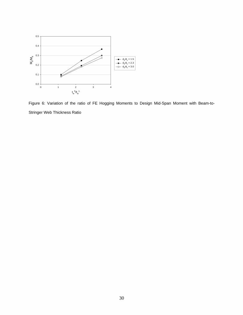
restrains the rotation of the stringers. Consequently, hogging moments are developed at their
ends. As shown in Table 1, the ends of the stringers hogging moment, hM , was about 10% of the
midspan moment of a simply supported beam, dM . The results of the parametric study revealed
that this moment is significantly increased with an increase in the ratio of the beam web
thickness to the stringer web thickness, sw
bw tt / , and decreased with an increase in the beam-to-
stringer depth ratio, sb dd (Figure 6).

13
In addition to the observed hogging moments that are unaccounted for in a typical design
of MSB’s, tensile forces are developed in the stringers and opposing compressive forces are
developed in the concrete slab. The horizontal restraint provided by the slab caused this axial
force to develop. The magnitude of the axial (tensile) force developed in the stringers (NFE)
could be as high as 39.5% of the total load (W) supported by the stringers, as shown in Table 1.
It is expected that the compressive force can be transmitted from the flange of the floor beam to
the slab by bearing of the flange on the concrete slab.
The stringers were redesigned accounting for the axial force and the reduced midspan
moment from the FE analysis. The design results revealed that a lighter section (W200X15 or
W8X10 imperial designation) would have been adequate thus providing a potential savings in
construction materials. An improved design methodology for floor stringers will therefore be a
useful tool for practical application and has been provided in a later section.
7.2 Floor beams
For the floor beams, the bending moments obtained from the FE analysis closely matched
that of the design moments at the selected sections. Table 2 shows a comparison between FE
results and design bending moments at the specified sections of the floor beam, shown in Figure
3 for the configuration / 1.16b sw wt t = , 1.5b sd d = , / 17.7s sL d = , / 0.8w sL d = . The close
agreement of the two corresponding sets of values demonstrates that the design moments for the
floor beams are accurate and do not need any modification. To some extent, this observation also
verifies the FE model since it agrees with the basic mechanics of the floor framing system. The

14
hogging moments at the ends of the stringers, however, resulted in some torsional moments in
the floor beams, which were found to have insignificant effect on the analyzed floor.
7.3 Stringer-to-floor beam welded connections
The floor stringer-to-floor beam welded connections are designed typically to resist only
shear forces. The FE analysis revealed that these welded connections experience bending stresses
due to the hogging moments developed at the ends of the stringers. In addition, these connections
are subjected to the effect of axial tensile forces. The capacity of the weld was reassessed under
the combined axial, shear and moments. The loads at weld joints are derived from the stress
results of the FE analysis. The total stress magnitude (total weld load) was evaluated using
classical weld stress analysis (Weaver, 1999), defined as
( ) ( )2 2
weld bending normal shearf f f f= + +
The results showed a significant increase in the weld stresses. The percentage increase in
the total weld load from the design assumption (shear only) to the actual case (shear, bending
and normal force) was about 226% for the configuration / 1.16b sw wt t = , 1.5b sd d = ,
/ 17.7s sL d = , / 0.8w sL d = . This suggests that the true behavior of the directly welded modular
steel floor framing connections may have a significant effect on the design of the connections
and on the behavior of the steel floor framing. Nevertheless, within the range of parameters
studied, it was observed that the weld provided in current practice (80% of the web of the
stringer) is adequate.
15
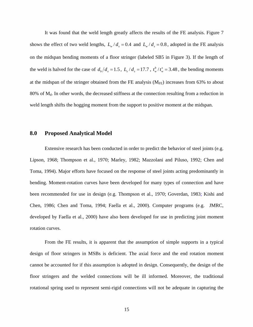
It was found that the weld length greatly affects the results of the FE analysis. Figure 7
shows the effect of two weld lengths, / 0.4w sL d = and / 0.8w sL d = , adopted in the FE analysis
on the midspan bending moments of a floor stringer (labeled SB5 in Figure 3). If the length of
the weld is halved for the case of 1.5b sd d = , / 17.7s sL d = , / 3.48b sw wt t = , the bending moments
at the midspan of the stringer obtained from the FE analysis (MFE) increases from 63% to about
80% of Md. In other words, the decreased stiffness at the connection resulting from a reduction in
weld length shifts the hogging moment from the support to positive moment at the midspan.
8.0 Proposed Analytical Model
Extensive research has been conducted in order to predict the behavior of steel joints (e.g.
Lipson, 1968; Thompson et al., 1970; Marley, 1982; Mazzolani and Piluso, 1992; Chen and
Toma, 1994). Major efforts have focused on the response of steel joints acting predominantly in
bending. Moment-rotation curves have been developed for many types of connection and have
been recommended for use in design (e.g. Thompson et al., 1970; Goverdan, 1983; Kishi and
Chen, 1986; Chen and Toma, 1994; Faella et al., 2000). Computer programs (e.g. JMRC,
developed by Faella et al., 2000) have also been developed for use in predicting joint moment
rotation curves.
From the FE results, it is apparent that the assumption of simple supports in a typical
design of floor stringers in MSBs is deficient. The axial force and the end rotation moment
cannot be accounted for if this assumption is adopted in design. Consequently, the design of the
floor stringers and the welded connections will be ill informed. Moreover, the traditional
rotational spring used to represent semi-rigid connections will not be adequate in capturing the

16
behavior of modular steel floor framing connections since it does not predict axial forces in
joints. In this section, an analytical model consistent with the behavior of modular steel floor
framing is proposed.
Figure 8 shows a schematic of the proposed model (hereafter referred to as the “B”
model). Members ab and cd represent the web of the floor beams at the ends of a floor stringer,
whose centerline is represented by bc . Using the slope deflection method, the following
relationship of the effective width of the floor beam web, B, the axial tension force developed in
the floor stringer as a result of the restraint by the floor slab, F, the distributed load, w, and the
geometric characteristics of the floor stringer and beam can be derived.
( ) ( )( )2
3 33
12 96
12b s b
b bw w
I I I h FBt wL LhF t
⇒ = =−
…………… (1)
where,
Ib,: Moment of inertia of the effective web of the floor beam.
Is: Moment of inertia of the floor stringer
w : Uniform load supported by the floor stringer.
h: the depth from the centerline of the floor stringer to the centerline of the top flange of the
floor beam
Ls: Span of the floor stringer
The results of the parametric study were analyzed and the effective width, B, for each
framing configuration was determined. A multiple regression analysis was conducted to
investigate the relationship between the effective width, B and the other parameters. In this

17
regression model, the dependent variable is the dimensionless parameter / bwB t (the ratio of the
effective width to the beam web thickness), and the predictor variables are the stringer length-to-
depth ratio ( /s sL d ), the ratio of the weld length to the depth of the floor stringer ( /w sL d ), the
ratio of the beam web thickness to the stringer web thickness ( sw
bw tt / ), and the floor beam-to-
stringer depth ratio ( sb dd ). Recognizing that the relationships between / bwB t and the individual
independent variables are exponential, two regression functions, exponential and linear
‘logarithmic’, were fitted for the combined parameters, using the principle of least squares. The
resulting regression functions were obtained as
ln 0 .03339 1.34444 1.65717
0.45610 6.97482
bs w w
b sw s s w
b
s
L L tBt d d t
dd
⎛ ⎞ ⎛ ⎞ ⎛ ⎞ ⎛ ⎞= − + −⎜ ⎟ ⎜ ⎟ ⎜ ⎟ ⎜ ⎟
⎝ ⎠ ⎝ ⎠ ⎝ ⎠ ⎝ ⎠⎛ ⎞
+ +⎜ ⎟⎝ ⎠
…………(2)
for the exponential function, and
ln 1.0723ln 0.7758ln 3.4783ln 1.0410ln 9.7399b
s w w bb sw s s w s
L L t dBt d d t d
⎛ ⎞ ⎛ ⎞ ⎛ ⎞ ⎛ ⎞ ⎛ ⎞= − + − + +⎜ ⎟ ⎜ ⎟ ⎜ ⎟ ⎜ ⎟ ⎜ ⎟
⎝ ⎠ ⎝ ⎠ ⎝ ⎠ ⎝ ⎠ ⎝ ⎠ …………(3)
for the linear ‘logarithmic’ function.
For both functions, the coefficient of determination, r2, was greater than 96.5%, which
indicates a strong relationship among the independent parameters and the effective width, B. The
F-statistic was used to determine whether such a high r2 value occurred by chance. The F-
observed statistic (382), for the exponential function, was substantially greater than the F-critical
value (2.53) indicating an extremely small probability (2.754E-36) that the high F value occurred
by chance. For the linear “logarithmic” function, the F-observed statistic was 594 and the

18
probability that it occurred by chance was 7.525E-41. Thus, it can be suggested that the
regression equations above will be very useful in predicting the assessed magnitude of the
effective width.
9.0 Design Methodology for Modular floor Framing
The design forces and moments in the floor beams agree with the results of the FE
analysis and hence no modification in the design methodology of floor beams is required. For
floor stringers and the welded connections, the following design methodology is suggested for
practical application:
Step 1. The configuration of the modular floor framing is selected and preliminary sizing
of framing components is performed.
Step 2. The dimensionless parameters /s sL d , /w sL d , sw
bw tt / , and sb dd are determined
from the preliminary dimensions.
Step 3. The dimensionless parameter / bwB t is evaluated from equations 2 and 3. This will
allow determining two values for the effective width, B, of the web of the floor
beam. The two values are expected to be almost matching as suggested by the
regression analysis.
Step 4. The inertia of the floor beam web is evaluated and used to analyze the model
shown in Figure 8.
Step 5. The axial force and the bending moments in the floor stringer are determined.

19
Step 6. The floor stringers are redesigned based on the forces and moments obtained in
step 5.
Step 7. Steps 2 to 6 are repeated until consistent sections are obtained which satisfy the
design criteria.
Step 8. The welded connection between the stringers and the floor beams is designed for
the shear, axial force, and moment obtained in step 5.
10.0 Summary and Conclusion
MSBs are fast becoming an effective alternative to conventional on-site constructed steel
buildings. The concept and detailing of these buildings have been documented in this paper,
which is expected to pave way for researchers to investigate other aspects of the technology
including activities such as lifting and other construction handling operations, and typical
modular steel construction details.
The paper has also investigated the most commonly used connection detail in modular
floor framing, which involves direct welding of floor stringers to floor beams. The structural
behavior of this connection in modular steel floor framing has been studied. The effect of this
behavior on the analysis and design of floor beams and stringers as well as the welded
connection was also studied. Results of the FE analysis revealed that consideration of the true
behavior of the directly welded connections in modular floor framing leads to distribution of
forces and moments that are different from the case of conventional steel building. The axial
forces developed in the floor stringers and the hogging moments at the ends of the floor stringers
are not predicted by the conventional assumptions adopted in current design practice by

20
designers of MSBs. Moreover, the traditional rotational springs used commonly to represent
semi-rigidity of connections fail to predict these axial forces. As explained earlier, these
unaccounted forces and moments would affect the design of the floor stringers and the
connection of the floor framing. The parametric study conducted in this study highlighted the
significance of these forces and moments. The study has demonstrated that the welds must have
the capacity to transfer significant bending moment and axial force in addition to the vertical
shear force from the floor stringer to the supporting beams. The study has also proposed an
analytical model, which will practically predict these forces and moments and will lead to a
reliable prediction of structural response of modular steel floor framing.
The results of the parametric study were used to develop regression functions that
describe the proposed model. Designers and manufactures of MSBs are advised to cautiously use
this model until it is experimentally validated.
Acknowledgements
The authors would like to express their gratitude for the financial support provided by the
National Sciences and Engineering Research Council of Canada (NSERC). The second author
would also like to acknowledge the immense transfer of knowledge of the subject from Mr.
Robert J. Murray, the principal of Murray Engineering, P.C., New York City.
21
References
Al-Emrani, M. and Kliger, R. (2003), “FE Analysis of Stringer-to-floor-beam connections in
Riveted Railway Bridges,” J. of Constructional Steel Research, 59, 803-818.
Astaneh, A., Nader, M. N., and Malik, L. (1989), “Cyclic Behavior of Double Angle
Connections,” ASCE J. of Structural engineering, Vol. 115, No. 5, 1101-1118.
Chen, W. F. and Toma, S. (1994), “Advanced Analysis of Steel Frames: Theory, Software and
Applications,” New Directions in Civil Engineering, CRC Press, Boca Raton, Florida.
CISC, Canadian Institute of Steel Construction (1997), “Handbook of Steel Construction (7th
edn.),” Universal Offset Limited, Canada.
CSI, Computers and Structures, Inc (2000), “SAP2000 Nonlinear Computer Program,”
Berkeley, USA.
Doerk, O., Fricke, W., and Weissenborn, C. (2003), “Comparison of different methods for
structural stresses at welded joints,” International J. of Fatigue, 25, 359-369.
Faella, C., Piluso, V. and Rizzano, G. (2000), “Structural Steel Semi-Rigid Connections: Theory,
Design and Software,” New Directions in Civil Engineering, CRC Press, Boca Raton, Florida.
Goverdan, A. V. (1983), “A collection of experimental moment-rotation curves and evaluation of
prediction equations for semi-rigid connections,” Vanderdilt University, Nashville, Tennesse.
Kishi, N. and Chen, W. F. (1986), “Steel Connection Data bank Program,” Structural
Engineering Report, No. CE-STR-86-18, School of Civil Engineering, Purdue University, West
Lafayette, Indiana.
Lawson, R. M., Grubb, P. J., Prewer, J. and Trebilcock, P. J. (1999), “Modular Construction
using Light Steel Framing: An Architect’s Guide,” The Steel Construction Institute Publication
SCI-P272, UK.

22
Lipson, S. L. (1968), “Single-angle and single-plate beam framing connections,” Canadian
Structural Eng. Conf., Toronto, Ontario, 141-162.
Marley, M. J. and Gerstle, K. H. (1982), “ Analysis and tests of flexible-connected steel frames,”
Engineering Structures, Vol. 8, No. 2, 107-118.
Mazzolani, F. M. and Piluso, V. (1992), “Evaluation of the Rotation Capacity of Steel Beams
and Beam-Columns,” 1st COST C1 Workshop, Strasbourg, 28-30 October.
MBABC (1997), Modular Building Association of British Columbia Newsletter, Fall 1997.
MBABC (2000), Modular Building Association of British Columbia Newsletter, Fall 2000.
Murray Engineering, P.C. (2000), “SUNY Purchase College Dormitory Construction
Drawings”, (materials obtained by personal communication with Mr. Robert J. Murray, P.E.,
Principal, Murray Engineering, P.C.).
NRCC, National Research Council Canada, (1995), “National Building Code of Canada,”
Printed in Canada.
Thompson, L. E., Mckee, R. J. and Visintainer, D. A. (1970), “An investigation of rotation
characteristic of web shear framed connections using A-36 and A-441 steel,” Department of
Civil Eng., University of Missouri-Rolla, MO.
Weaver, M. A. (1999), Determination of Weld Loads and Throat Requirements Using Finite
Element Analysis with Shell Element Models – A Comparison with Classical Analysis, Welding
Research Supplement (April 1999).

23
Table 1. Comparison of FE results with Design Forces and Moments for Stringer Beams
SB1 SB2 SB3 SB4 SB5 SB6
Mid-Span Moment (Design) Md, (kNm) 22.28 22.03 22.03 22.03 30.8 18.26
Mid-Span Moment (FE) MFE, (kNm) 20.2 20.09 20.14 20.05 27.75 16.54
MFE as a percentage of Md (%) 90.66 91.19 91.42 91 90.1 90.58
Hogging Moment at end of span (Design) Mh, (kNm) 0 0 0 0 0 0
Hogging Moment at end of span (FE) Mn, (kNm) 2.08 1.94 1.89 1.98 3.05 1.72
Mn as a percentage of Md (%) 9.34 8.81 8.58 9 9.9 9.42
Axial Force (Design) Nd, (kN) 0 0 0 0 0 0
Axial Tensile Force (FE) NFE, (kN) 15.16 18.55 19.08 18.14 21.79 13.84
Total Load on Beams excl. self wt. W (kN) 48.74 48.2 48.2 48.2 67.68 39.82
NFE as a percentage of W (%) 31.1 38.49 39.59 37.63 32.2 34.76
FLOOR STRINGERSConfiguration Considered
/ 1.16b sw wt t =1.5b sd d = / 17.7s sL d = / 0.8w sL d =

24
Table 2. Comparison of FE results with Design Bending Moments at Sections of Floor Beam
900 (K1) 3550 (K2) 6100 (K3) 8100 (K4)Bending Moment at section (Design) Md, (kNm) 44.83 91.57 -21.93 71
Bending Moment at section (FE) Ma, (kNm) 44.44 91.34 -21.34 69.22
Ma as a percentage of Md (%) 99.13 99.75 97.3 97.49
Sections of Main Beam, measured from point A (mm)Configuration Considered
1.5b sd d = / 1.16b sw wt t = / 17.7s sL d = / 0.8w sL d =

25
Building Length
Bui
ldin
g W
idthA A
M#4-3 Floor
M#4-2 Ceiling
3rd
Floo
rM
odul
e2n
d Fl
oor
Mod
ule
M#5-2 Ceiling
M#5-3 Floor
BoltThreeSides
Cast in Place Concrete
B
M#1-3 Floor
M#1-2 Ceiling
2nd
Floo
rM
odul
e3r
d Fl
oor
Mod
ule
ColumnCapPlate
Symbols:ColumnHorizontal Module ConnectionBraced Frame
B
M#6M#5M#4M#3M#2M#1
FB a
nd C
BFSCS
Brac
e
BraceFBFBC
BC
B
FS FS
CSCS
FB
CB
FS
CS
Sec. A-A: Horizontal Connection
Sec. B-B: Vertical Connection
HC VC
Figure 1: A Typical Floor/Ceiling Framing of a Four-Storey Modular Steel Structure

26
Ceiling Beam (Typ.)
Ceiling Stringer (Typ.)
Con
cret
e Fl
oor
Floor Stringer
Finished ceiling
Floor Stringer
First Floor
(Typ)
Cle
ar H
eigh
t
Floor Stringer
Floor Beam (Typ.)
Floor Stringer
Second Floor
column (Typ.)
Floo
r To
Floo
r Hei
ght
Shi
ppin
g H
eigh
t
Figure 2: A Section of a Typical Modular Floor Assembly

27
SB5SB
1
3600
mm
W310X39
7000 mm=4x1750 mm
SB3SB
2
SB4
W310X39
LL = 3.6 kN/m2
7000 mm2500 mmS
B6
W20
0X21
(typ
ical
)
LL = 4.8 kN/m2CL
K1 K2 K3 K4
Figure 3: Layout of Modular Floor Framing adopted for FE Study

28
Figure 4: Finite Element Mesh

29
twb/tw
s
0 1 2 3 4
MFE
/Md
0.0
0.2
0.4
0.6
0.8
1.0
db/ds = 1.5db/ds = 2.3db/ds = 3.0
Figure 5: Variation of FE-to-Design Midspan Moment Ratio with Beam-to-Stringer Web Thickness Ratio
for different Beam-to-Stringer Depth Ratios
30
twb/tw
s
0 1 2 3 4
Mh/M
d
0.0
0.1
0.2
0.3
0.4
0.5
db/ds = 1.5db/ds = 2.3db/ds = 3.0
Figure 6: Variation of the ratio of FE Hogging Moments to Design Mid-Span Moment with Beam-to-
Stringer Web Thickness Ratio

31
twb/tw
s
0 1 2 3 4
MFE
/Md
0.0
0.2
0.4
0.6
0.8
1.0
40% weld length80% weld length
Figure 7: Variation of FE-to-Design Midspan Moment Ratio with Beam-to-Stringer Web Thickness Ratio
for different weld lengths

32
s
FF
h
w
h
tbwFloor StringerFloor
Beam
a
b
d
c
L
Figure 8. Schematic of the proposed Model