effect of crash pulse shape on scat stroke … · nasa technical paper 3126 effect of crash pulse...
TRANSCRIPT
NASA Technical Paper 3126
Effect of Crash Pulse Shape on Scat StrokeRequirements for Limiting Loads on Occupantsof AircraftHuey D. Carden
February 1992
https://ntrs.nasa.gov/search.jsp?R=19920008811 2018-07-29T04:48:02+00:00Z

Summary
An analytical study wasmade to (1) provide com-parative information on various crash pulse shapes
that potentially could be used to test seats to the pa-rameter conditions included in Federal RegulationsPart 23 x 23.562(b)(1) for dynamic testing of gen-
eral aviation seats, (2) show the e�ects that crashpulse shape can have on the seat stroke requirementsnecessary to maintain a speci�ed limit loading onthe seat/occupant under various vertical crash pulse
loadings, (3) compare results from certain analyti-cal model pulses with approximations of actual crashpulses, and (4) compare analytical seat results from
application of the speci�ed test parameters of theseat test regulation with experimental airplane crashdata. Equations for �ve models of potentially usefulpulse shapes were derived which express the displace-
ment of the aircraft structure and the displacement ofthe seat/occupant in terms of the maximum deceler-ation, velocity change, limit seat pan load, and pulsetime. From these equations, analytical seat stroke
data were obtained under the test conditions as spec-i�ed in Federal Regulations Part 23 x 23.562(b)(1) fordynamic testing of general aviation seats.
Introduction
With the advent of transportation vehicles camesometimes unwanted application of suddenly applied
accelerations to human occupants of such vehicles.Abnormal accelerations, for example, arise in air-planes from the impact of the vehicle with the ground
during a crash. Research in aviation crash dynamicsdates back to the pioneering work of Hugh De Havenin the 1940's. De Haven survived a midair collisionand the ensuing crash of an airplane to later initi-
ate crash research through on-site investigations ofaircraft accidents to identify components and sub-systemswhich contributed to injury and fatality. Re-
sults from this work produced design guidelines thatremain pertinent today (ref. 1) and can still be foundin production of agricultural airplanes (refs. 2 and 3).
E�orts to appraise the hazards of these acceler-ations to humans are found in reference 4. From
this and other literature, it is apparent that whole-body human tolerance to sudden acceleration de-pends upon many factors, such as (1) direction of
acceleration application, (2) magnitude of the accel-eration, (3) duration of the acceleration, (4) onsetrate of the acceleration, and (5) how the occupant'sbody is supported during application of the accelera-
tion. Furthermore, various parts of the human bodyare able to withstand di�erent magnitude and dura-tion of acceleration prior to sustaining injury. For
example, accelerations perpendicular to the spine of
between 30g (0.15-sec duration) and 40g (0.05-secduration) were tolerated by well-restrained human
subjects compared with between 5g (0.15-sec dura-tion) and 15g (0.05-sec duration) for an accelerationapplied along the spine (ref. 4). Consequently, whentolerance to crash loads of human sub jects in the gen-
eral population is discussed, often a vertical (alongthe spine) g load of about 12g to 15g with a durationof approximately 0.10 sec is mentioned. However, in
recent years, the emphasis has shifted to ameasure ofspinal load in the pelvic region of a 49 CFR (Code ofFederal Regulations) Part 572 dummy which is con-sidered more meaningful than a g load for assessing
the consequences of crash loads on humans.
One means of providing a degree of protectionto passengers in aircraft during a crash situation isthe seat/restraint system. Various studies have ad-
dressed concepts to enhance survivability in crashsituations through a load-limiting seat which pro-vides stroking distance under reduced and controlledloads (refs. 5 to 12). Additionally, guidelines for
dynamic testing of general aviation seats, whichwere proposed by the General Aviation Safety Panel(GASP) (ref. 13) and subsequently placed into Fed-
eral Regulations (ref. 14), are intended to achievesome degree of occupant protection in crash situ-ations. Speci�cally, one of the regulations relativeto dynamic tests of aircraft seat/restraint systems
given by x 23.562(b)(1) states, \For the �rst test,the change in velocity may not be less than 31 feetper second. The seat/restraint system must be ori-
ented in its nominal position with respect to the air-plane and with the horizontal plane of the airplanepitched up 60 degrees, with no yaw, relative to theimpact vector. For seat/restraint systems to be in-
stalled in the �rst row of the airplane, peak decel-eration must occur in not more than 0.05 sec afterimpact and must reach a minimum of 19g. For all
other seat/restraint systems, peak deceleration mustoccur in not more than 0.06 sec after impact andmust reach a minimum of 15g."
Compliance criteria covering all the regulationsare included in reference 14; however, the focus of
this paper is x 23.562(7) which states, \The com-pression load measured between the pelvis and lum-bar spine of the ATD may not exceed 1500 pounds."
(ATD designates anthropomorphic test dummy.) Asnoted in reference 15, experimental crush data forvertebrae (T8 through T12 and L1 through L5) in-dicate that the crushing force ranged from slightly
over 1300 to 2360 lb. The T9 thoracic vertebrae ofthe spine (carrying 60 lb which is the estimated up-per body weight of a 50-percentile man) was crushed
at approximately 1500 lb. Based upon this and other
1

considerations (for example, ref. 16), the criterion be-came 1500 lb.
Since the regulations in Part 23 do not specify
any particular pulse shape to achieve the requiredmagnitudes and durations of the seat loadings in alaboratory environment, the purpose of this paper is
to (1) provide comparative information for variouspulse shapes that potentially could be used to testseats to meet the regulation, (2) show the e�ectsthat crash pulse shape can have on the seat stroke
requirements necessary to maintain a speci�ed limitloading on the seat/occupant under various vertical
crash pulse loadings, (3) compare results from certain
analytical model pulses with the approximations ofactual crash pulses, and (4) compare the speci�edtest parameters of the regulation to airplane crashtest data.
Symbols
a deceleration, ft/sec2
as deceleration of seat/occupant,
ft/sec2
ATD anthropomorphic test dummy
DRI dynamic response index
g acceleration due to gravity, ft/sec2
Gl l imit deceleration on seat pan,g units
Gm maximum deceleration magnitude of
crash pulse, g units
k sti�ness of dynamic response indexmodel, lb/ft
K ratio of seat pan limit decelerationto maximum deceleration magni-
tude of pulse, Gl=Gm
m mass, slugs
S seat stroke, (SS � SA)12, in.
SA displacement of airframe, ft
SS displacement of seat/occupant, ft
t time, sec
tf maximum duration of seat panloading, sec
tL time to reach seat pan maximumdeceleration, sec
tm maximum pulse duration of trape-zoidal, skewed or symmetric trian-
gle, and quarter-sine crash pulses(one-half pulse duration or rise timeof half-sine crash pulse), sec
tr rise time to peak deceleration(skewed, or symmetric triangle or
trapezoidal pulse), sec
V velocity, ft/sec
VA velocity of airframe during crashpulse, ft/sec
Vo initial impact velocity, ft/sec
VS velocity of seat/occupant duringcrash pulse, ft/sec
VS;1 velocity of seat/occupant at time tLin crash pulse, ft/sec
VS;2 velocity of seat/occupant betweentimes tL and tf in crash pulse,
ft/sec
�Z peak of input acceleration for
dynamic response index model,g units
�m maximum displacement of dynamicresponse index model, ft
�t pulse duration of accelerationapplied to dynamic response indexmodel, sec
!n natural frequency of dynamicresponse index model, rad/sec
� damping coe�cient of dynamicresponse index model
Analysis
The photographic sequence in �gure 1 illustrates
the crash dynamics of a general aviation type, single-engine airplane test specimen. The nose landing gearof the airplane specimen contacted the impact surface
with an initial velocity, ight-path angle, pitch, roll,and yaw angle. High-speed motion pictures of thecrash show the nose gear starting to collapse andthe engine cowling contacting the impact surface
0.028 sec after initial ground contact, followed bythe starboard wing tip at 0.035 sec. The windshieldbegan to de ect and the �re wall started to penetrate
the cabin at 0.060 sec. At the same time, the aftsection of the fuselage began to deform, and thestarboard landing gear contacted the impact surface.The port landing gear contacted the impact surface
at 0.13 sec into the impact, and the port wingimmediately thereafter broke away from the fuselageat the aft spar and rotated forward around the front
spar.
2
The approximate pitch attitude was retained dur-ing crash impact. At 0.15 sec, the aft cabin sec-
tion pitched forward about 10� as a result of mainlanding-gear springback. The airplane then settledback to an angle of about 45� and continued to skidbefore stopping. The fuselage cabin remained at
about the same pitch, roll, and yaw angles as at theinitial impact attitude. Obviously, as indicated bythe discussion of the sequence of �gure 1, a crash
is a complex occurrence with a variety of parame-ters contributing to the airframe load during impact.Aerodynamic, elastic, and plastic structural defor-mation; inertial forces; and frictional forces interplay
to remove the kinetic energy of the airplane and tochange the path of the airplane from the conditionsjust prior to impact. As these events occur, seats and
occupants respond to the loads and motions of thecrash.
Assumptions and idealizations are made con-cerning the crash event and the behavior of theseat/occupant and aircraft structure. Under these
assumptions and idealizations, equations are pre-sented for the aircraft structural stroke (crushing)and the seat/system displacement as a function of
the change in vertical impact velocity for various to-tal pulse durations and pulse shapes where the seatlimit design load has been chosen as 12g. Includedin the crash load pulse information are test pulses
which could satisfy conditions for testing of generalaviation seats as proposed by the General AviationSafety Panel (GASP) (ref. 13) and could be subse-
quently included in Federal Regulations Part 23|Airworthiness Standards (ref. 14), hereinafter calledPart 23.
In this section, equations are derived for (a) thecrushing distance of aircraft structure which would
be necessary to produce the idealized crash pulseshapes and (b) the displacement of the seat/occupantsystem. With these equations, the required stroke
of the seat relative to the aircraft that would benecessary tomaintain a limit 12g load on the seat panof the seat/occupant undergoing the vertical loadingof the particular crash pulse can be determined. It
is again emphasized that Federal Regulations Part23 speci�es a maximum load (as opposed to a g
limit) in the pelvis of an ADT of 1500 lb. The 12g
seat pan limit is discussed relative to the 1500-lbfcriteria and an often used technique for evaluatingoccupant response to dynamic inputs, the dynamicresponse index (DRI). The DRI is a one-degree-of-
freedom, damped, spring mass model of the uppertorso (spine) derived from Air Force experiments(ref. 15). The index is the maximum acceleration
response in g units to inputs to the spinal model
which has a natural frequency of 52.9 rad/sec anddamping ratio of 0.224.
Assumptions and Idealizations
The crash event of an aircraft as depicted in �g-ure 1 is generally a very complex sequence of events,but a good understanding of the structural responseand seat/occupant behavior can be obtained by sim-
plifying analytical techniques. Knowledge of the lim-itations and assumptions of the analyses is required.Useful trends and typical phenomena associated with
the crash eventmay be studied successfully with suchtechniques.
Figure 2 presents the various assumed and ideal-ized analytical models of the crash loadings for which
required seat stroke distance for maintaining a limitload on the seat pan has been derived. The idealizedshapes include
Trapezoidal pulse (�g. 2(a))Half-sine wave (�g. 2(b))Quarter-sine wave (�g. 2(c))Skewed triangular pulse (�g. 2(d))Symmetric triangular pulse (�g. 2(e))
In the derivation of equations for the analytical mod-
els of the crash loading pulses, the vertical and longi-tudinal behavior is assumed to be uncoupled; that is,the in uence of longitudinal loads on vertical loads
is not considered in any of the equations or data pre-sented. The seat/occupant combination is assumedto follow the structure loading up to the limit load ofthe seat pan, and no dynamic overshoot is considered
in the behavior of the seat pan response. The totalvertical impact velocity is assumed to be removed atthe end of the crash pulse, and the seat/occupant
velocity is also assumed to be reduced to zero at theend of the seat pan limit loading pulse duration. Noassumptions are made concerning the availability ofactual crushable aircraft structure necessary to pro-
duce the crash pulses under consideration nor whatseatmechanism could provide the stroking distances.
Appropriate equations derived in the section\Trapezoidal Pulse Load" and the equations pre-
sented in the appendix for the other pulse shapeswere solved with a commercial computer program ona personal computer. The solutions provided decel-
eration and seat stroke data for the plots presentedin the section \Results and Discussion."
Trapezoidal Pulse Load
In this section, equations are derived for thetrapezoidal pulse loading shape that provides the
necessary magnitude, rise time to peak loading,and velocity change speci�ed by Federal RegulationsPart 23 for dynamic seat testing (ref. 14.). A detailed
3

derivation is presented only for the trapezoidal pulseshape (sketch A). In the appendix only the equations
are given for the other pulse shapes. Results usingthe equations for these pulse shapes are presented asplots of deceleration versus velocity change and seatstroke in the section \Results and Discussion."
a
0 tL
tr t
m tf
as
= -Glg
a = -Gm
g
a = -Gm
g(t/tr)
Sketch A
For aircraft structure, the velocity during the
particular trapezoidal deceleration pulse can be ex-pressed as
VA = Vo +
Z t
0a dt (1)
where 0 � t � tr , and substituting for a (sketch A)gives
VA = Vo +
Z t
0�Gmg
�t
tr
�dt (2)
Integrating equation (2) gives
VA = Vo +
"�Gmg
t2
2tr
!# t0
(3)
which evaluates at t = tr to be
VA = Vo� Gmgtr
2(4)
Equation (4) is the velocity history of the aircraft upto time t r of the trapezoidal crash loading. Usingequation (3) now to determine the aircraft displace-ment as the integral of the velocity gives
SA =
Z t
0VA dt (5)
or
SA =
Z t
0
Vo � Gmg
t2
2tr
!dt (6)
Integrating equation (6) gives
SA = Vot
#t0
+Gmgt3
6tr
# t0
(7)
Evaluation at t = tr gives
SA = Votr � Gmgt2r6
(8)
which is the general expression for the displacement
of the aircraft up to time tr of the trapezoidal decel-eration. For the time tr < t < tm ,
VA = Vo� Gmgtr
2+
Z t
t r�Gmg dt (9)
Integrating and evaluating at t = tm for which
VA = 0 give
Vo =
�Gmg
2
�(2tm � tr) (10)
Thus the total airplane displacement at t = tm is
SA = Votr � Gmgt2r6
+
Z tm
tr
�Vo� Gmg
tr
2� Gmg(t � tr)
�dt (11)
which integrates and evaluates in the limits to
SA = Votm � Gmgt2r6�
�Gmg
tm
2
�(tm � t r) (12)
For the seat/occupant, the total displacement is
SS =
Z tL
0VS;1 dt +
Z t f
tL
VS;2 dt (13)
where for 0 < t � tL,
VS;1 = Vo +
Z t
0a dt (14)
which evaluates within the limits, after substituting
a = �Gmg(t=t r) and integrating, to be
VS;1 = Vo �Gmgt2
2t r(15)
Additionally, for tL < t,
VS;2 =
�Vo +
Z t
0a dt
�+
Z t
tL
as dt (16)
4
which upon appropriate substitution of a = �Gmg�(t=tr) and as = �Glg, integration, and evaluation
within the limits is
VS;2 = Vo �Gmgt2L2t r
�Glg(t � tL) (17)
and the total seat/occupant displacement is, in termsof equations (15) and (17),
SS =
Z tL
0
Vo �Gmg
t2
2tr
!dt
+
Z tf
tL
"Vo � Gmg
t2L2tr
� Glg(t� tL)
#dt (18)
Upon integration and evaluation of equation (18), the
total seat/occupant displacement is found to be
SS = Votf + Gmgt3L3tr
� Gmgt2Ltf
2tr
�
Glg
2(tf � tL)
2 (19)
An equation for time tf is also required. Since att = tf , VS;2 = 0, equation (17) can be used todetermine tf . Thus, recalling Vo from equation (10)and de�ning
K =tLtr
=Gl
Gm
and noting that
tL = Ktr
give the solution for the time to be
tf =1
2K
"2(tm + KtL)�
t2r + t2Ltr
#(20)
For speci�c velocity changes and maximum g of thetrapezoidal pulse, time tm can be determined as
tm =Vo
Gmg+
tr
2(21)
Since seat stroke is eventually desired, the seat/occupant displacement minus the airplane displace-
ment gives the stroke of the seat or
S =
"Votf +Gmg
t3L3tr
� Gmgt2Ltf
2tr�
Glg
2(tf � tL)
2
#
�
"Votm �Gmg
t2r6�Gmg
tm
2(tm � tr)
#(22)
Derivation of similar equations for the other pulse
loading shapes is not included ; however, pertinentequations similar to those presented above for thetrapezoidal pulse are included in the appendix. The
equations allow seat strokes to be determined for theother pulse shapes.
Results and Discussion
In �gures 3 through 8, peak deceleration Gm isplotted as a function of initial impact velocity Vo orseat stroke S for several chosen pulse durations tmor rise times tr . A line is drawn vertically from aninitial impact velocity (to be dissipated under thecrash pulse) up to a desired pulse duration (or risetime) curve and extended horizontally to the value
of the peak deceleration which would be necessaryto achieve the velocity change. Where the horizontalline intersects the seat stroke curve (for the same
pulse duration, or rise time), a vertical line is drawnto the abscissa to indicate what seat stroke would berequired to limit the deceleration to a 12g level on the
seat pan.
In discussing the results of the seat stroke require-
ments under the various pulse shape loadings, thevelocity change of 31 ft/sec and rise time to peakdeceleration of 0.05 or 0.06 sec (associated with Fed-
eral Regulations Part 23 for GA dynamic seat testing,ref. 14) are used as the reference point.
Trapezoidal Pulse Loading
The �rst pulse shape considered is the trapezoidalpulse which is characterized by a sloped line rising toa peak value which remains constant until all the ve-
locity involved in the impulse is removed. Figure 3(a)presents the peak deceleration and seat stroke datafor the �xed rise time to a peak of 0.05 and 0.06 sec,respectively, with a �xed total pulse duration tm(computed from the peak deceleration of 19g, witha change in velocity of 31 ft/sec for the 0.05-sec risetime or from the peak deceleration of 15g peak with
a change in velocity of 31 ft/sec for the 0.06-sec risetime speci�ed in Part 23). At the Part 23 require-ment of change in velocity of 31 ft/sec, rise time topeak deceleration of 0.05 sec, a 19g value is obtained.
Likewise, for the 0.06-sec rise time, the 15g peak isalso possible. For these parameters, a seat stroke of2.6 and 1.2 in., respectively, is indicated to maintain
the load on the seat pan to a 12g limit.
5

Additionally, in �gure 3(b) with compressedscales, experimental peak decelerations at their re-
spective velocity changes have been plotted for thegeneral aviation aircraft tests which were conductedat the Langley Research Center. (See refs. 17and 18.) With the exception of four data points,
all the general aviation crash data lie outside theboundaries formed by the vertical line through thevelocity change of 31 ft/sec and the horizontal line
through the peak deceleration of 19g. The indica-tion is that the Part 23 test values relative to thesimulated real world crash data can be termed asminimum requirements for the dynamic testing of
general aviation seats. Since the results in �gure 3(a)indicate stroking of the seats is required under thespeci�ed test parameters and since most data in �g-
ure 3(b) are higher in magnitudes than the stated re-quirements, seat stroking capability would be highlydesirable to attempt to provide a measure of protec-tion to occupants undergoing crash loads.
Sine Pulse Loadings
Half-sine pulse. Figure 4 presents peak decel-eration as a function of velocity change for di�erent
pulse durations of the half-sine crash pulse along withthe required seat stroke to achieve the reduced seatpan loading under the various assumed peak mag-
nitudes of the half-sine crash pulse. For total pulsedurations between 0.065 and 0.120 sec, correspond-ing to velocity changes of 16 to 30 ft/sec with a peakpulse magnitude of 12g, no seat stroke would be re-
quired. However, for a vertical velocity change of31 ft/sec with a 0.10-sec duration (rise time to peak= 0.05 sec) the seat would have to stroke approxi-
mately 1 in. at the design limit load (12g) to pro-vide protection from the 15g maximum decelerationpulse loading. Note, however, that Part 23 requiresa 0.06-sec rise time with the 15g peak input decel-
eration. Furthermore, the input magnitude of 19g isonly possible with a pulse duration of approximately0.081 sec (Rise time = 0.0405 sec, not the required
0.05 sec). Seat stroke for the 19g pulse is about 3 in.If the pulse duration were 0.065 sec, the decelerationpeak is 23g and a seat stroke of about 4.5 in. wouldbe necessary for occupant protection.
Quarter-sine pulse. Figure 5 presents thedeceleration and stroke results for the quarter-sinepulse loading. As expected, the data are not dramat-
ically di�erent from the half-sine pulse loading dis-cussed in the previous section. Similarly, the Part 23parameters of velocity change of 31 ft/sec with a time
to peak deceleration of 0.05 sec cannot be ful�lledwith this particular shape. For example, a peak valueof 19g with a velocity change of 31 ft/sec requires
a total duration of 0.081 sec (which is also the risetime to peak) of the quarter-sine pulse, whereas the
speci�cation is 0.05 sec. With a pulse magnitude of15g with velocity change of 31 ft/sec, the duration is0.1 sec, and for the 0.05-sec pulse at velocity changeof 31 ft/sec, just over 30g is indicated which is much
too high a peak loading compared with the peak of19g stated in the Part 23 speci�cation. At the load-ing of 30g, about 5.4 in. of seat stroke is indicated.
Triangular Pulse Loadings
The following sections discuss the triangular-
shaped pulses, the skewed and the symmetrical, rel-ative to the e�ect that shape has on seat stroke andoccupant response under dynamic loads. The trian-
gular pulse was found to approximate well the actualcrash pulses measured during the GA Crash Dynam-ics Program. (See refs. 17 and 18.) For the study ofthis paper, one nonsymmetrical pulse and one sym-
metrical triangular pulse were selected. The di�cultyof generating and controlling the drop-o� of triangu-lar pulse shapes in a laboratory is one reason that
the Part 23 regulation speci�es only the peak decel-eration and rise time to peak with a velocity changerather than a total pulse shape. Generating suchparameters is easier in a laboratory if the form is a
trapezoidal pulse shape, and additionally, both re-quirements of Part 23 can be readily achieved withsuch a shape.
Skewed triangle. Data for the skewed triangu-lar loading pulse are presented in �gure 6. With the
velocity change of 31 ft/sec of Part 23, a pulse dura-tion of 0.1 sec essentially gives the peak decelerationof 19g; however, the curves in �gure 6 are for a rise
time to the peak deceleration being 7/8 of the totalpulse duration or for the 0.1-sec pulse duration underconsideration, 0.088 sec. Therefore, the pulse gives,as stated, approximately the correct velocity change
and the peak deceleration but does not provide thedesired rise time to peak deceleration. Although thisparticular skewed triangular loading does not provide
all the desired test parameters for seat testing underPart 23, it does indicate that at a velocity changeof 31 ft/sec, 0.1 sec, and a peak deceleration of 19g,about 1 in. of seat stroke should be provided to limit
the load on the seat pan to the design limit of 12g.
Symmetric triangle. For the triangular shape
where the rise time is half the total pulse duration,a symmetric triangular loading exists. Figure 7(a)presents peak deceleration and seat stroke data for
the symmetric triangular loading pulse shape. For apulse duration of 0.1 sec (rise time of 0.05 sec) anda velocity change of 31 ft/sec, the peak deceleration
6

of 19g is achieved, and approximately 0.5 in. of seatstroke would be necessary to limit the loads on the
seat pan to the limit of 12g which is being used inall the examples of this paper. For comparison, ex-perimental crash pulse data are included with thetrapezoidal pulse and are also shown on compressed
scales in �gure 7(b). The primary emphasis of thisplot is, therefore, that the parameters suggested forthe testing of seats under dynamic inputs as con-
tained in the Part 23 regulations are \minimum re-quirements" relative to the crash data from full-scaleaircraft tests. A second point is that, even underwhat has been stated to be a minimum requirement,
seat stroking capability for the protection of seat oc-cupants is strongly suggested from the data of �g-ure 7 as well as the other pulse shapes included in
this paper.
Trapezoids and Triangles
It should be noted that a skewed triangular pulsewith a rise time of 0.06 sec and total pulse durationof 0.128 sec can provide the peak deceleration of
15g and velocity change of 31 ft/sec as speci�ed byPart 23. However, as mentioned previously, practicalconsiderations such as the di�culty of generating andcontrolling the drop-o� of triangular pulse shapes led
the GASP panel to recommend that the requirementbe stated as peak loads, times, and velocity changeswith the unstated being that a trapezoidal type pulse
that can be achieved in a laboratory could ful�ll thestated requirements.
A question may arise \How do the responses un-der the trapezoidal pulse inputs compare with trian-gular pulses which were found to approximate closelythe actual crash pulses in the GA testing?" Figure 8
shows a comparison of a triangular and a trapezoidalpulse with rise time of 0.05 sec and a triangular and atrapezoidal pulse with rise time of 0.06 sec. It may be
noted that the trapezoidal pulses (open symbols) areconservative , since they require slightly more strokein the seat to limit the loads on the seat pan than thecomparable triangular pulses (closed symbols). For
example, the 0.05-sec trapezoidal pulse at 19g, veloc-ity change of 31 ft/sec, requires a seat stroke of about2.5 in., whereas the 0.1-sec triangular pulse requires
only about 1.5 in. Similarly, the 0.06-sec trapezoidalpulse requires just over 1 in. of stroke, whereas the0.128-sec triangular pulse requires no stroke. Thus,the trapezoidal pulse which is easier to generate ex-
perimentally provides some conservatism in the tests,which is a desirable situation. This is especially goodsince it has been shown that the stated peak decel-
erations and velocity change of the requirements are
generally below the actual aircraft crash test results
(see �gs. 3(b) and 7(b)).
Response Considerations of Dummy
Occupant
Data relative to the response behavior of thedummy occupant under controlled inputs are pre-sented in �gures 9 and 10. As noted in reference 17,the DRI is one of several means often used for assess-
ing potential responses of occupants to crash inputs.Although the DRI is a simple model (�g. 9), it in-troduces into consideration dynamic response under
crash pulse inputs. If, for example, the resulting 12gcontrolled trapezoidal limit load pulse on the seatpan location (resulting from the trapezoidal and sym-metrical triangular input crash pulses of the present
study) is used as an input to the DRI model, directcomputations indicate the response to be a DRI ofabout 17:2g. The impulse or product of the 12g max-
imum load on the seat pan (and input to the occu-pant) and time Gltf (1.2 to 1.3 sec for the trapezoidaland symmetrical triangular input pulses) can be re-lated to the DRI. For instance, in �gure 10 (which is
a plot of normalized DRI response as a function ofthe impulse, ref. 17), the response at the 1.2 impulsevalue is in a region that ampli�es by approximately1.4 the essentially trapezoidal input pulse that the
occupant experiences at the seat pan. Thus the 12glevel translates to a DRI in the occupant of approxi-mately 17g from �gure 10 which was also veri�ed by
direct computations of DRI.
In reference 16, the test results of both energy-absorbing and non-energy-absorbing seats were ob-
tained under application of Part 23 input pulse.Pelvic forces as a function of DRI were monitored inthe tests series and a DRI of approximately 19g was
found to correlate with 1500 lbf in the pelvis of thedummy occupant. Such results would indicate that(since seat stroke was included in the present study)the 17g DRI is probably a fairly good estimate of
the value that would be experienced by the dummywith control of the load on the seat pan to the 12glevel, and consequently, the 1500 lbf pelvic force level
would likely not be exceeded. Additionally, such re-sults further emphasize the need for designed seatstroking to provide for some occupant protection incrash situations.
Conclusions
An analytical study has been made of the e�ects
of pulse shape models (which potentially could beused to simulate actual crash pulses) on the requiredstroking of aircraft seats to maintain a design limit
load on the seat pan during the particular crash pulse
7

application. Equations for �ve assumed shapes ofcrash pulse loadings were derived to express the dis-
placement of the aircraft structure and the displace-ment of the seat/occupant in terms of the maximumdeceleration, velocity change, limit seat load, andpulse time. Seat stroke data were computed under
test conditions as speci�ed in Part 23 x 23.562(b)(1)for dynamic testing of general aviation seats. An ex-amination of the results and a comparison of the data
to full-scale crash test data for aircraft indicated thefollowing conclusions:
1. One pulse, the trapezoidal, was capable of
providing the required parameters of bothtest conditions speci�ed in the Part 23x 23.562(b)(1) regulation.
2. The symmetrical triangle was capable of pro-viding only the required parameters of thehighest input pulse speci�ed in the Part 23x 23.562(b)(1) regulation.
3. The half-sine, quarter-sine, and one speci�cskewed triangular pulse could not provide therequired inputs for seat testing speci�ed in the
Part 23 x 23.562(b)(1) regulation.
4. Adjustments in the skew of the triangularpulse to provide a rise time of 0.06 sec with a
total pulse duration of 0.128 sec would permitthe skewed triangle to provide the necessarypeak g level and velocity change only for thelower input pulse requirement of the Part 23
x 23.562(b)(1) regulation.
5. Essentially all �ve di�erent pulse shapes at ornear the Part 23 x 23.562(b)(1) regulation of
19g occurring at 0.05 sec, or 15g occurring at0.06 sec with a velocity change of 31 ft/sec,require seat stroke to limit the loads on the
seat pan (and consequently on the occupant)to a design limit below the peak input value.
6. A comparison of the speci�ed seat test param-
eters of the Part 23 regulation with full-scalecrash test data from the NASA General Avi-ation Crash Test Program indicated that therequired test conditions can be readily termed
a minimum requirement for the testing of gen-eral aviation seats.
NASA Langley Research Center
Hampton, VA 23665-5225
December 19, 1991
8
Appendix
Equations for Evaluating Seat Stroke
Requirements for Di�erent PulseLoading Shapes
Presented in this appendix are the equations forevaluating the seat stroke requirements for pulseloading shapes which include the half-sine, quarter-sine, skewed triangular, and symmetrical triangular
pulses. The detailed derivation is not included, butthe steps are essentially identical to those for thetrapezoidal pulse in the main text.
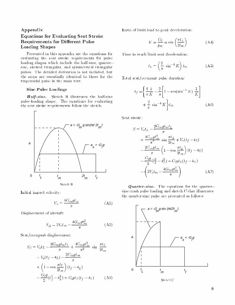
Sine Pulse Loadings
Half-sine. Sketch B illustrates the half-sinepulse-loading shape. The equations for evaluatingthe seat stroke requirements follow the sketch.
a
0 tL t
m tf
as
= -Glg
a = -Gm
g sin(πt/ 2tm
)
2tm
Sketch B
Initial impact velocity:
Vo =4Gmgtm
�(A1)
Displacement of aircraft:
SA = 2Votm �4Gmgt
2m
�(A2)
Seat/occupant displacement:
SS = VotL �2GmgtmtL
�+
4Gmgt2m
�2sin
�tL
2tm
+ Vo(tf � tL)�2Gmgtm
�
�
�1� cos
�tL
2tm
�(tf � tL)
�
Glg
2(t2f � t2L)+ GlgtL(tf � tL) (A3)
Ratio of limit load to peak deceleration:
K =Gl
gm= sin
��tL
2tm
�(A4)
Time to reach limit seat deceleration:
tL =
�2
�sin�1K
�tm (A5)
Total seat/occupant pulse duration:
tf =
(4
�
1
K�
2
�
"1� cos(sin�1 K)
1
K
#
+2
�sin�1K
)tm (A6)
Seat stroke:
S = VotL �2GmgtmtL
�
+4Gmgt
2m
�2sin
�tL
2tm+Vo(tf � tL)
�
2Gmgtm
�
�1� cos
�tL
2tm
�(tf � tL)
�
Glg
2(t2f � t2L)+GlgtL(tf � tL)
�
2Votm �
4Gmgt2m
�
!(A7)
Quarter-sine. The equations for the quarter-sine crash pulse loading and sketch C that illustrates
the quarter-sine pulse are presented as follows:
a
0 tL t
m tf
as
= -Glg
a = -Gm
g sin (πt/2tm
)
SketchC
9

Initial impact velocity:
Vo =2Gmgtm
�(A8)
Displacement of aircraft:
SA =4Gmgt
2m
�2(A9)
Seat/occupant displacement:
SS = VotL �2GmgtmtL
�+
4Gmgt2m
�2sin
�tL
2tm
+ Vo(tf � tL)�2Gmgtm
�
�
�1� cos
�tL
2tm
�(tf � tL)�
Glg
2(t2f � t2L)
+ GlgtL(tf � tL) (A10)
Ratio of limit load to peak deceleration:
K =Gl
Gm= sin
�tL
2tm(A11)
Time to reach limit seat deceleration:
tL =
�2
�sin�1 K
�tm (A12)
Total seat/occupant pulse duration:
tf =2tm
�
�1
Kcos(sin�1 K)+ sin�1K
�(A13)
Seat stroke:
S =
"VotL �
2GmgtmtL
�+
4Gmgt2m
�2sin
�tL
2tm
+ Vo(tf � tL)�2Gmgtm
�
�1� cos
�tL
2tm
�(tf � tL)
�
Glg
2
�t2f � t2L
�+ GlgtL(tf � tL)
#
�
4Gmgt2m
�2(A14)
Triangular Pulse Loadings
Equations for the skewed triangular pulse loading
and the symmetrical triangle, which is a specialcase of the skewed shape, are presented. Sketch Dillustrates the skewed triangular pulse loading shape;
sketch E, the symmetrical triangle.
a
0 tL
tr t
m tf
as
= -Gl
g
a = -Gm
g[1+ tr
/(tm
- tr
)]
a = -Gm
g(t/tr
)
+ Gm
g[t /(tm
- tr
)]
Sketch D
a
0 tL
tr t
m tf
as
= -Glg
a = -Gm
g[1 + tr
/(tm
- tr
)]
a = -Gm
g(t/tr
)
+ Gm
g[t /(tm
- tr
)]
Sketch E
Initial impact velocity:
Vo =Gmgtm
2(A15)
Displacement of aircraft:
SA = Votm �Gmgt
2r
6�
Gmgtr
2(tm � tr)
�
1
2
Gmgtm
tm � tr
�t2m � t2r
�+Gmgtmtr
�
Gmgt2r
2+
Gmg
6(tm � tr )(t3m � t3r ) (A16)
Seat/occupant displacement:
SS = Votf +Gmgt
3L
3tr�Gmg(t
2L)
tf
2tr�
Glg
2(tf � tL)
2
(A17)
10

Ratio of limit load to peak deceleration:
K =Gl
Gm(A18)
Time to reach limit seat deceleration:
tL = K
�78
�tm (Skewed)
tL =�K2
�tm (Symmetrical)
9>=>; (A19)
(7/8 has been assumed for the skewed triangle, whereas1/2 is used for the symmetrical triangle).
Total seat/occupant pulse duration:
tf =tm
2
�1
K+
7
8K
�(A20)
thus,
S =
"Votf +
Gmgt3L
3tr�Gmg
�t2L
� tf
2tr
�
Glg
2(tf � tL)
2
#
�
"Votm �
Gmgt2r
6�
Gmgtr
2(tm � tr)
�
1
2
Gmgtm
tm � tr
�t2m � t2r
�+ Gmgtmtr
�
Gmgt2r
2+
Gmg
6(tm � tr)(t3m � t3r)
#(A21)
11

References
1. De Haven, Hugh: Causes of Injury in Lightplane Acci-
dents. Aero Dig., vol. 44, no. 5, Mar. 1, 1944, pp. 51{55,
206.
2. Hasbrook, A. Howard: What a Spray Plane ShouldHave.
Aviation Week, vol. 52, no. 7, Feb. 13, 1950, pp. 25{27,
30{31.
3. Hoekstra, Harold D.; and Huang, Shung-Chai: Safety in
General Aviation. Flight Safety Found., Inc., 1971.
4. Eiband, A. Martin: Human Tolerance to Rapidly Applied
Accelerations: A Summary of the Literature. NASA
MEMO 5-19-59E, 1959.
5. Pinkel, I. Irving; and Rosenberg,EdmundG.: Seat Design
for Crash Worthiness. NACA Rep. 1332, 1957. (Super-
sedes NACA TN 3777.)
6. Fasanella, Edwin L.; and Alfaro-Bou, Emilio: NASA
General Aviation Crashworthiness Seat Development.
[Preprint] 790591, Soc. of Automotive Engineers,
Apr. 1979.
7. Svoboda, Craig M.; and Warrick, James C.: Design and
Development of Variable-Load Energy Absorbers. Rep.
No. NADC-80257-60, U.S. Navy, June 1981. (Available
from DTIC as AD A103 206.)
8. Alfaro-Bou, Emilio; Fasanella, Edwin L.; and Williams,
M. Susan: Crashworthy Design Considerations for Gen-
eral Aviation Seats. SAE Tech. Paper Ser. 850855,
Apr. 1985.
9. Eichelberger, Charles P.; Alfaro-Bou, Emilio; and
Fasanella, Edwin L.: Developmentof an Energy-Absorbing
Passenger Seat for a Transport Aircraft. 19th Aerospace
Mechanisms Symposium, NASA CP-2371, 1985,
pp. 39{58.
10. Shane, S. Joseph: Design and Testing of an Energy-
Absorbing Crewseat for the F/FB-111 Aircraft . Vol-
ume I|Final Report. NASA CR-3916, 1985.
11. Shane, S. Joseph: Design and Testing of an Energy-
Absorbing Crewseat for the F/FB-111 Aircraft . Vol-
ume II|Data From Seat Testing. NASA CR-3917, 1985.
12. Shane, S. Joseph: Design and Testing of an Energy-
Absorbing Crewseat for the F/FB-111 Aircraft . Vol-
ume III|Data From Crew Module Testing. NASA
CR-3918, 1985.
13. Soltis, Stephen J.; and Olcott, John W.: The Devel-
opment of Dynamic Performance Standards for General
Aviation Aircraft Seats. SAE Tech. Paper Ser. 850853,
Apr. 1985.
14. Small Airplane Airworthiness Review Program, Amend-
ment No. 1; Final Rule|14 CFR, Part 23. Fed. Regist.,
vol. 53, no. 157, Aug. 15, 1988, pp. 30802{30815.
15. Payne, Peter R.; and Stech, Ernest L.: Dynamic Models
of the Human Body. AMRL-TR-66-157, U.S. Air Force,
Nov. 1969. (Available from DTIC as AD 701 383 and also
available as NASA TM X-67038.)
16. Chandler, Richard F.: Data for the Development of Cri-
teria for General Aviation Seat and Restraint System
Performance. Crash Dynamics of General Aviation Air-
craft, SP-622, Soc. of Automotive Engineers, Inc., 1985,
pp. 13{28. (Available as SAE Paper 850851.)
17. Carden, Huey D.: Correlation and Assessment of Struc-
tural AirplaneCrash Data With Flight Parameters at Im-
pact. NASA TP-2083, 1982.
18. Carden, Huey D.: Impulse Analysis of Airplane Crash
Data With Consideration Given to Human Tolerance.
SAE Tech. Paper Ser. 830748, Apr. 1983.
12
REPORT DOCUMENTATION PAGEForm Approved
OMB No. 0704-0188
Public r eporting burden for this co llection of information is estimated to a vera ge 1 hour per response, including the time for reviewing instr uctions, sear ching ex isting data source s,g ather ing and maintaining the data needed, and completing and reviewing the co llection o f inf ormation. Send comments r egar ding this burden estimate or any o ther a spect of thisco llection of inf ormation, including sugg estions for r educing this burden, to Washington Headquar ter s Se rvices, Dir ectora te fo r Information Operations and Repo rts, 1 21 5 J e�ersonDav is Highway, Suite 12 04 , Arlington, VA 222 02 -4 30 2, and to the O�ce o f Mana gement and Budg et, Paperwork Reduction Pr oject (07 04 -0 18 8), Washing ton, DC 2 05 03 .
1. AGENCY USE ONLY(Leave b lank) 2. REPORT DATE 3. REPORT TYPE AND DATES COVERED
February 1992 Technical Paper
4. TITLE AND SUBTITLE
E�ect of Crash Pulse Shape on Seat Stroke Requirements forLimiting Loads on Occupants of Aircraft
6. AUTHOR(S)
Huey D. Carden
7. PERFORMING ORGANIZATION NAME(S) AND ADDRESS(ES)
NASA Langley Research CenterHampton, VA 23665-5225
9. SPONSORING/MONITORING AGENCY NAME(S) AND ADDRESS(ES)
National Aeronautics and Space AdministrationWashington, DC 20546-0001
5 . FUNDING NUMBERS
WU 505-63-50-09
8 . PERFORMING ORGANIZATION
REPORT NUMBER
L-16941
10. SPONSORING/MONITORING
AGENCY REPORT NUMBER
NASA TP-3126
11 . SUPPLEMENTARY NOTES
12a. DISTRIBUTION/AVAILABILITY STATEMENT 12b . DISTRIBUTION CODE
Unclassi�ed{Unlimited
Subject Category 39
13 . ABSTRACT (Maximum 200 words)
An analytical study was made to (1) provide comparative information on various crash pulse shapes thatpotentiallycould be used to test seats under conditions included in Federal Regulations Part 23 x 23.562(b)(1)for dynamic testing of general aviation seats, (2) show the e�ects that crash pulse shape can have on the seatstroke requirements necessary to maintain a speci�ed limit loading on the seat/occupant during crash pulseloadings, (3) compare results from certain analytical model pulses with approximations of actual crash pulses,and (4) compare analytical seat results with experimental airplane crash data. Structural and seat/occupantdisplacement equations in terms of the maximum deceleration, velocity change, limit seat pan load, and pulsetime for �ve potentially useful pulse shapes were derived; from these, analytical seat strokedata were obtainedfor conditions as speci�ed in Federal Regulations Part 23 x 23.562(b)(1) for dynamic testing of general aviationseats.
14 . SUBJECT TERMS 15. NUMBER OF PAGES
Crashworthiness; Crash dynamics; Human tolerance; General aviation seats; Seattesting
2116. PRICE CODE
A0317 . SECURITY CLASSIFICATION 18. SECURITY CLASSIFICATION 19 . SECURITY CLASSIFICATION 20. LIMITATION
OF REPORT OF THIS PAGE OF ABSTRACT OF ABSTRACT
Unclassi�ed Unclassi�ed
NSN 7540-01-280-5500 Standard Form 298(Rev. 2-89)Pre scr ibed by ANSI Std. Z39-1 82 98 -1 02
NASA-Lang le y, 1 99 2