effect of corrosion on the low-cycle fatigue strength of ... tests were carried out in air at 90 °c...
TRANSCRIPT

Procedia Engineering 133 ( 2015 ) 528 – 534
1877-7058 © 2015 Published by Elsevier Ltd. This is an open access article under the CC BY-NC-ND license (http://creativecommons.org/licenses/by-nc-nd/4.0/).Peer-review under responsibility of CETIMdoi: 10.1016/j.proeng.2015.12.626
ScienceDirectAvailable online at www.sciencedirect.com
6th Fatigue Design conference, Fatigue Design 2015
Effect of corrosion on the low-cycle fatigue strength of steels used in frequent start-up power generation steam turbine
Mohamed EL MAYa*, Nicolas SAINTIERa, Olivier DEVOSb, Alexia ROZINOERc aArts et Métier ParisTech I2M, CNRS UMR 5295 - 33405 Talence, France
bUniversité de Bordeaux, CNRS UMR 5295 - 33405 Talence, France cGeneral Electric Oil & Gas - Thermodyn SAS - 71200 Le Creusot, France
Abstract
The practical importance of fatigue failure in steam turbine materials has directed many experimental research towards assessing the physical reason for material sensitivity to corrosion fatigue and providing design rules for engineers. Metallic materials used in steam turbine are exposed to cyclic loading at high temperature and steam environment, during their service life. In this study, an original fatigue testing setup was developed to investigate the effect of aqueous solutions and temperature on the fatigue strength on the martensitic stainless steel X19CrMoVNbN11-1 used for rotating blades and (ii) a cast G17CrMoV5-10 steel used for casing. Fatigue tests were carried out in two environments: (i) in air at 90°C and (ii) in distilled water at 90°C (pH = 7.2 and 02 = 3 ppm) at a loading frequency of 1 Hz. Internal and surface crack initiation are observed in air at 90°C, whereas in purified water at 90°C, the crack initiated in the surface at corrosion defects. The decrease observed in the corrosion fatigue strength of specimens was more important at high plastic strain level of that on similar specimens tested in air. Based on fractography analysis, fatigue crack initiation mechanisms in air and in distilled water were identified. Two different scenarios for fatigue damage depending on the microstructure are proposed and will be discussed in this paper. © 2015 The Authors. Published by Elsevier Ltd. Peer-review under responsibility of CETIM.
Keywords: steam turbine ; corrosion fatigue strength ; aqueous solutions ; in-situ electrochemical measurements ; corrosion fatigue crack initiation mechanism.
* Corresponding author. Tel.: +33 5 56 84 53 47; fax: +33 5 56 84 53 66.
E-mail address: [email protected]
© 2015 Published by Elsevier Ltd. This is an open access article under the CC BY-NC-ND license (http://creativecommons.org/licenses/by-nc-nd/4.0/).Peer-review under responsibility of CETIM

529 Mohamed El May et al. / Procedia Engineering 133 ( 2015 ) 528 – 534
Nomenclature
A Fracture elongation (in %) UTS Ultimate tensile strength under quasi-static monotonic tension YS Conventional yield strength with 0.2% plastic deformation E Young modulus εa Strain amplitude
Median fatigue strength (in strain amplitude) at 2×10⁴ cycles in air at 90 °C under R = −1 R Loading ratio f Loading frequency Nf Number of cycles to failure Kt Theoretical stress concentration factor Ra Arithmetic surface roughness
1. Introduction
Current industrial design is heavily concerned with the effect of corrosion on fatigue strength of mechanical components and structures. The combined influence of corrosion and cyclic loading is known to affect the mechanical properties of metallic alloys and has been shown to initiate cracks from corrosion-induced surface defects [1-7]. Corrosion fatigue damage is related to synergetic effects of mechanical/electrochemical. These effects are governed by many parameters: mechanical, metallurgical, physicochemical and electrochemical factors.
Corrosion fatigue has been studied mainly in aqueous environments at room temperature by numerous researchers [1-7]. A number of crack initiation mechanisms have been suggested, including competition between pit growth and short crack growth [1,4], preferential dissolution of plastically deformed material [2], local rupture of the passive film by persistent slip bands (PSB) [3,7] and hydrogen embrittlement in the cathodic domain and deformation/corrosion synergy effects [4]. However, all these mechanisms depend on the experimental conditions (loading frequency, stress–strain level, environment, temperatures, imposed electrochemical potential value, etc.) and on material properties (e.g., cleanness, segregation, porosities etc.).
Steam turbines materials, developed for frequent start-up, are exposed to cyclic loading, thermal stresses and steam environments during their service lives. In the Low Pressure (LP) part of the steam turbine, an aqueous solution is formed when the expanding steam start condensating (Wilson curve). Rotating blade material has been mainly investigated on aqueous environment. Indeed, few works in the literature treat the effect of the corrosion induced by saturated steam, at 100 °C and 1 atm, on the fatigue strength [8-10].
The purpose of this paper is to understand the initiation mechanism for corrosion fatigue cracking on two materials used in steam turbine. The corrosive environment chosen for fatigue tests in this study is a distilled water at 90°C to investigate the effect of the condensation of steam in the LP part.
2. Materials and experimental procedure
2.1. Material
Two materials were investigated in this study: a martensitic stainless steel X19CrMoVNbN11-1, used for rotating blades and a cast G17CrMoV5-10 steel, used for casing. Their chemical composition and mechanical properties under quasi-static monotonic tension are shown in Tables 1 and 2. The microstructure of the X19CrMoVNbN11-1 steel is completely martensitic as shown in Fig. 1.a. The microstructure of the G17CrMoV5-10 presents porosities due to casting process (Fig. 1.b).

530 Mohamed El May et al. / Procedia Engineering 133 ( 2015 ) 528 – 534
Table 1. Chemical compositions.
Material %C %Cr %Mo %Mn %Ni %Nb %V %Si
X19CrMoVNbN11-1 0.16 - 0.22 10 - 11.5 0.5 - 1 0.3 - 0.8 0.3 - 0.8 0.15 - 0.05 0.1 - 0.3 0.1 - 0.5
G17CrMoV5-10 0.15 - 0.2 1.2 - 1.5 0.9 - 1.1 0.5 - 0.9 ≤ 0.64 0.22 - 0.3 ≤ 0.6.
Table 2. Mechanical properties under monotonic quasistatic tensile at 90°C
Material E (GPa) UTS (MPa) YS (MPa) A(%)
X19CrMoVNbN11-1 211 910 768 31
G17CrMoV5-10 207 665 559 16
Fig. 1. (a) Martensitic structure observed with chemical attack (Villela) on X19CrMoVNbN11-1; (b) Porosities observed without chemical attack on G17CrMoV5-10.
2.2. Fatigue tests conditions
Low Cycle fatigue (LCF) tests in air and in distilled water were performed using 8 mm diameter cylindrical specimens with a theoretical stress concentration factor in tension equals to Kt = 1.04. The arithmetic roughness of the area of interest was less than or equal to Ra = 0.1 μm for all the specimens. All the fatigue tests were performed at 1 Hz with a servo-hydraulic fatigue testing machine (load cell capacity of 100 kN) under a fully reversed load (R=-1). The stop criterion for fatigue tests was a maximum load drop of 10 %, corresponding to a technical fatigue crack with a typical surface length of 5 mm and a depth of 2-3 mm.
LCF tests were carried out in air at 90 °C using a three controlled zones furnace according to the ASTM E606-04 standard. LCF tests in distilled water at 90 °C were carried out under axial loading and strain controlled at the free potential of the material. An electrochemical corrosion cell (Fig.2) was developed at the laboratory. This cell allows in situ fatigue testing in an aqueous corrosive environment at temperatures up to 90 °C. The aqueous solution is heated outside the corrosion cell with a thermostatic bath equipped with an external circulation pump. The specimens were electrically isolated from the frame of the fatigue testing machine. The distilled water quality in the corrosion cell was monitored during corrosion fatigue test using a pH electrode and dissolved oxygen electrode.
Finally, the fracture surfaces of all the specimens were observed with optical and scanning electron microscopy (SEM) to investigate the crack initiation mechanisms.
531 Mohamed El May et al. / Procedia Engineering 133 ( 2015 ) 528 – 534
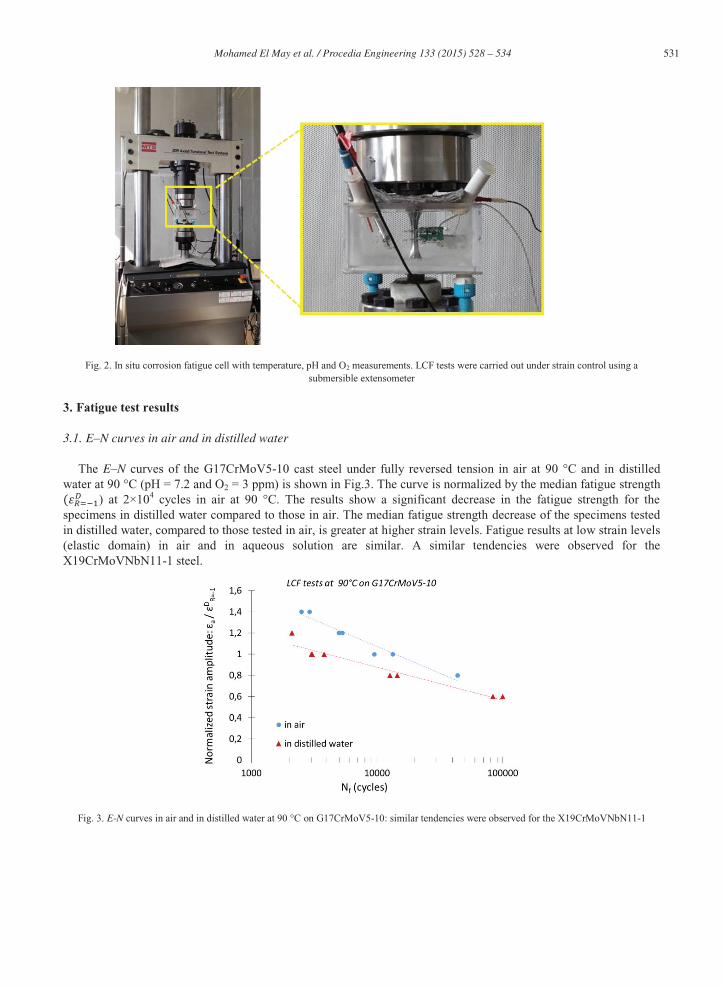
Fig. 2. In situ corrosion fatigue cell with temperature, pH and O2 measurements. LCF tests were carried out under strain control using a submersible extensometer
3. Fatigue test results
3.1. E–N curves in air and in distilled water
The E–N curves of the G17CrMoV5-10 cast steel under fully reversed tension in air at 90 °C and in distilled water at 90 °C (pH = 7.2 and O2 = 3 ppm) is shown in Fig.3. The curve is normalized by the median fatigue strength
) at 2×10⁴ cycles in air at 90 °C. The results show a significant decrease in the fatigue strength for the specimens in distilled water compared to those in air. The median fatigue strength decrease of the specimens tested in distilled water, compared to those tested in air, is greater at higher strain levels. Fatigue results at low strain levels (elastic domain) in air and in aqueous solution are similar. A similar tendencies were observed for the X19CrMoVNbN11-1 steel.
Fig. 3. E-N curves in air and in distilled water at 90 °C on G17CrMoV5-10: similar tendencies were observed for the X19CrMoVNbN11-1

532 Mohamed El May et al. / Procedia Engineering 133 ( 2015 ) 528 – 534
3.2. Fatigue crack initiation sites
For the blade material (X19CrMoVNbN11-1), the SEM observations show that the fatigue crack initiation sites in air at 90°C are located on the specimen surface (indicated by arrows in Fig. 4.a). No clear evidence of defects (pores, inclusions, etc.) was found at the crack initiation locations. For the fatigue test in distilled water at 90 °C, fatigue cracks initiated at surface corrosion defects (pits) (indicated by arrows in Fig. 4.b).
The SEM observations for the casing material (G17CrMoV5-10), show that the fatigue cracks initiated around corrosion pits developed in porosities (indicated by arrows in Fig. 5.b) in distilled water at 90 °C. For the fatigue test in air, internal and surface fatigue crack initiation sites are observed (indicated by arrows in Fig. 5.a). Fatigue cracks initiation sites in air 100 kN of are located around casting defects (porosities).
Fig. 4. Crack initiation sites on the X19CrMoVNbN11-1: (a) in air at 90 °C and (b) under corrosion fatigue in distilled water at 90 °C.
Fig. 5. Crack initiation sites on the G17CrMoV5-10: (a) in air at 90 °C and (b) under corrosion fatigue in distilled water at 90 °C.

533 Mohamed El May et al. / Procedia Engineering 133 ( 2015 ) 528 – 534
4. Discussion
Corrosion fatigue tests in distilled water at 90 °C show a significant decrease of fatigue strength compared to fatigue results obtained in air at 90 °C. Unlike the case of aqueous environment at 20 °C, aqueous environments at elevated temperatures are known to play a significant role in the fatigue crack initiation process [2, 3]. In the theory, the corrosion activity is accelerated by the temperature of the electrolyte. The role of aqueous environment in the fatigue crack initiation process can be attributed to the local deformation-induced corrosion due to: (i) protective passive film destruction for stainless steel and/or (ii) anodic material zones. This can explain the decrease of fatigue strength in distilled water at 90 °C. We note that the fatigue strength decrease is more important for high cyclic strain (load) values on the studied materials (Fig. 3).
4.1. Corrosion fatigue crack initiation mechanism on the X19CrMoVNbN11-1
In case of the martensitic stainless steel X19CrMoVNbN11-1, the passive film thickness is less than 10 nm [6]. At high strain amplitudes, the passive layer is damaged by cyclic plasticity. Consequently, the steel react with the water at 90°C to restore the passive film. During this process, iron is consumed, i.e., by the oxidation with the oxygen free boiler water, and a notch corrosion defect is formed. At high cyclic deformation, the breaking of the passive film is repeated at every fatigue cycle. The corrosion defect progresses and a corrosion fatigue crack initiates around the defect. With the decreasing of strain amplitude, the life of the passive layer is extended and the fatigue damage development decrease. When the strain amplitude is below the fatigue limit of the passive film, this one is not damaged and the corrosion process is inhibited, the fatigue strength of the stainless steel is determined only by the fatigue process. In this range the fatigue strength in water and in air are similar.
4.2. Corrosion fatigue crack initiation mechanism on the G17CrMoV5-10
Fig. 6. Crack initiation site on the G17CrMoV5-10 tested in distilled water at 90 °C: several corrosion pits are developed in the surface of the specimen during fatigue test
For the cast steel (G17CrMoV5-10), fatigue crack initiation is controlled by the porosities formed during the casting process of the steel. In air at 90 °C, fatigue cracks initiate around porosities due to the local stress concentration. Indeed, internal and surface fatigue cracks were observed on fatigue specimen tested in air at 90°C (fig 5.a). Several fatigue criterion for material with defect deal with the role of the size and the morphology of the defect on the fatigue strength [11-13]. In general, crack initiates around the larger porosity. The G17CrMoV5-10 steel contains lower chromium, less than 1.5 wt %, compared to the stainless steel X19CrMoVNbN11-1. Such, the material is not protected by a resistant passive layer at the surface. This material is affected by a general corrosion process in aqueous solution. But, at high strain amplitude, we observed the development of pits at the surface of the

534 Mohamed El May et al. / Procedia Engineering 133 ( 2015 ) 528 – 534
specimens (Fig. 6). Corrosion fatigue cracks on this material are initiated around corrosion pits developed in surface porosity sites. Due to local confinement, the corrosion medium in the porosity is more aggressive than the distilled water. Moreover, this phenomenon is assisted by the preferential dissolution of iron in anodic zones induced by the local deformation. This is confirmed by the existence of many pits in the surface of the tested specimens at high cyclic deformation amplitude. The transition between pit/crack is depended on the imposed deformation amplitude values. At low cyclic deformation, the fatigue strength in distilled water and in air are similar.
5. Conclusion
In this paper, the fatigue crack initiation process of X19CrMoVNbN11-1 and G17CrMoV5-10 in air at 90 °C was identified. It was also shown that there is a significant decrease in the fatigue strength under corrosion for all the tested materials investigated in distilled water at 90 °C (pH = 7.2 and O2 = 3 ppm) compared to the fatigue strength in the air. However, at relatively low imposed deformation amplitudes, the fatigue strength in distilled water and in air are similar. Based on SEM observations of tested specimens, a scenario for corrosion fatigue crack initiation mechanisms is proposed for each materials. This results show that the load amplitudes occurring during start-up and shutdown at stress concentration points in the turbine design has to be taken into account in design phase. Additionally, in low-pressure Steam turbine part, impurities in the expanding steam start condensating in the form of concentrated salts. The effect of these contaminants on the corrosion fatigue strength in aqueous solution should be also considered to propose design rules against corrosion fatigue for steam turbine.
Acknowledgements
This work was carried out in the framework of the EUROGIA+ project “CSPIMP”, with the financial support of DGCIS. The authors thankfully acknowledge the industrial partners for the project, General Electric Oil and Gas Thermodyn S.A.S, General Electric Oil and Gas Nuovo Pignone S.r.l. and Acciona Energia S.A., and the academic partners at the PROMES laboratory of the CNRS (Perpignan University, France).
References
[1] Y. Kondo, Prediction of fatigue crack initiation life based on pit growth, Corrosion, 45; 1979, p. 7–11. [2] S. Xu, X.Q. Wu, E.H. Han, W. Ke, Y. Katada, Crack initiation mechanisms for low cycle fatigue of type 316Ti stainless steel in high temperature water, Mat Sci Eng A, 490; 2008, p. 16–25. [3] C. Laird, DJ. Duquette, Mechanisms of fatigue crack nucleation. In: Devereux O, McEvily AJ, Staehle RW, (editors). Corrosion fatigue: chemistry, mechanics and microstructure, vol. 2. Houston, Texas: National Association of Corrosion Engineers (NACE); 1973. p. 88. [4] T. Palin-Luc, R. Pérez-Mora, C. Bathias, G. Domínguez, P.C. Paris, J.L. Arana, Fatigue crack initiation and growth on a steel in the very high cycle regime with sea water corrosion, Eng Fract Mech, 77; 2010, p. 1953–1962. [5] R. Pérez-Mora, T. Palin-Luc, C. Bathias, P. C. Paris, Very high cycle fatigue of a high strength steel under sea water corrosion: A strong corrosion and mechanical damage coupling, International Journal of Fatigue, V 74; 2015, p. 156-165 [6] R. Ebara, Y. Yamada, A. Goto, Corrosion fatigue behaviour of 13Cr stainless steel and Ti-6Al-4V ultrasonic frequency. Fatigue ultrasonore, TMS; 1980. [7] M. El May, T. Palin-Luc, N. Saintier, O. Devos, Effect of corrosion on the high cycle fatigue strength of martensitic stainless steel X12CrNiMoV12-3, International Journal of Fatigue, V47; 2013, p. 330-339. [8] R. Ebara, “Fatigue ultrasonore, chapter Corrosion fatigue behavior of 13Cr stainless steel and Ti- 6Al-4V ultrasonic frequency”, TMS editions; 1980. [9] R. Ebara, T. Kai and K. Inoue, “Corrosion-fatigue Technology”, chapter: Corrosion fatigue behavior of 13Cr stainless steel in sodium-chloride aqueous solution and steam environment, ASTM STP 642; 1978, p. 155. [10] H. Ouchida, Kikai-gakkai Rombun-shu, Vol. 19; 1953, p. 27-34. [11] Y. Murakami, Effect of small defects and inhomogeneities on fatigue strength: experiments, model and applications to industry. ECF 11, Poitiers, France; 1996, p. 31-42. [12] T. Palin-Luc, and S. Lasserre, An energy based criterion for high cycle multiaxial fatigue. Eur. J. Mech. A/Solid, 17; 1998, p. 237 [13] Y. Nadot, and T. Billaudeau, Multiaxial fatigue limit criterion of defective materials. Engng. Fract. Mech., 73(1); 2006, p. 112-133.