eeeem - defense technical information center · table of contents page no. table of contents...
TRANSCRIPT
84DR4 92 MEASUREMENTS OF ELONGATIONAL V15COMETRY USING R FIBER i/1SPINNING TECHNIQUE. -(U) DEFENCE RESEARCH ESTABLISHMENTSUFFIELD RALSTON (ALBERTA) M D GAUTHIER MAYER ET AL.
UNCLASSIFIED FEB 84 DRES-SR-377 F/G 20/4 NL
EEEEm ~h-

w 16
1111 1. M16E2
MICROCOPY RESOLUTION TEST CHARTNATIOAM BURkA&-OF STANDARDS- 1963-A
U% * ::;
VI c-1. a% F. -
oefe* nationals UNCLASSIFIEV'
SUFFIELD REPORTv NO. 377
MEASUREMENTS OF ELONGATIONAL VISCOMETRY USING16 A FIBER SPINNING TECHNIQUE
' PART 1: MODIFICATIONS TO THE SANGAMO SCHLUMBERGER
ELONGATIONAL VISCOMETER MODEL E4 (U)
by
M.D. Gauthier Mayer, W.J. Fenrick and S.J. Armour
A'IL. 8LJ_.1
PCN No. 13E10
9 DTICE- -ECTE
February 1984 PR 1 11984
FF
-DFINCE RESEASC ISTASLISINT Su i: -RALSTON: ALRTA
Sa*. P'stc
g4 04 10 160
UNCLASSIFIED
DEFENCE RESEARCH ESTABLISHMENT SUFFIELD
RALSTON ALBERTA
SUFFIELD REPORT NO. 377
MEASUREMENTS OF ELONGATIONAL VISCOMETRY USING
A FIBER SPINNING TECHNIQUE
PART I: MODIFICATIONS TO THE SANGAMO SCHLUMBERGER
ELONGATIONAL VISCOMETER MODEL E4 (U)
by
M.D. Gauthier Mayer, W.J. Fenrick and S.J. Armour
PCN No. 13E10 Accession ForNTIS GRA&IDTVr7 T-B
vv
op
' .
S * * 9 *~\*.f. .oj'....~

UNCLASSIFIED
TABLE OF CONTENTS
Page No.
TABLE OF CONTENTS
ABSTRACT
ACKNOWLEDGEMENTS
UST OF TABLES
UST OF FIGURES
LIST OF FIGURES IN APPENDIX i
INTRODUCTION .................................................... 1
DESCRIPTION OF THE VISCOMETER .............................. 2
APPARATUS TESTING ............................................. 3
DESIGN MODIFICATIONS .......................................... 7
SUMMARY AND CONCLUSIONS .................................... 9
REFERENCES ....................................................... 1 I
APPENDIX I
SANGAMO SCHLUMBERGER BROCHURE ON ELONGATIONAL VISCOMETER
APPENDIX 1i
DRAWINGS OF DESIGN MODIFICATIONS
UNCLASSIFIED
4f.
".. **.-. - ..**.. .p." -.. . . .u i i - ~ l . .* l il>:li miiill *.*..i *.l~li. *,*** l %i" *%*i **' .-
UNCLASSIFIED
DEFENCE RESEARCH ESTABLISHMENT SUFFIELDRALSTON ALBERTA
SUFFIELD REPORT NO. 377
MEASUREMENTS OF ELONGATIONAL VISCOMETRY USING
A FIBER SPINNING TECHNIQUE
PART I: MODIFICATIONS TO THE SANGAMO SCHLUMBERGERELONGATIONAL VISCOMETER MODEL E4 (U)
by
M.D. Gauthier Mayer, W.i. Fenrick and S.J. Armour
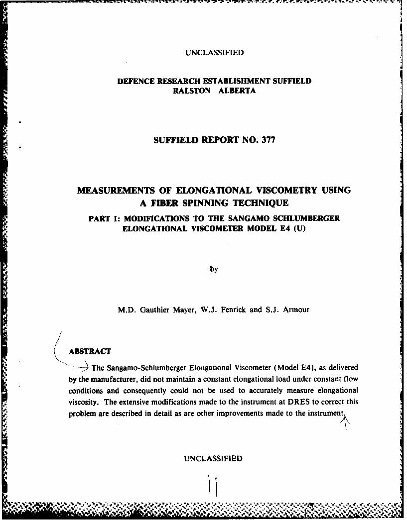
ABSTRACT
The Sangamo-Schlumberger Elongational Viscometer (Model E4), as delivered
by the manufacturer, did not maintain a constant elongational load under constant flow
conditions and consequently could not be used to accurately measure elongational
viscosity. The extensive modifications made to the instrument at DRES to correct this
*_ problem are described in detail as are other improvements made to the instrument.
UNCLASSIFIED
*€
5 ?. ?-;?. '.....?. ?y . .. ..... . ...jW% V:'' ' • ' ..- ,. Nb, V P., -- .,

-T I T -. F -,
UNCLASSIFIED
'I-
ACKNOWLEDGEMENTS
The authors would like to thankProfessor A.B. Metzner
for many productive discussionsthroughout the course of this work.
A
UNCLASSIFIED
..... ,
.. "

UNCLASSIFIED
LIST OF TABLES
I Relevant Physical Properties of the Newtonian Fluids Tested
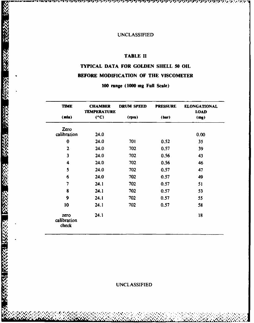
11 Typical data for Golden Shell 50 Oil before Modifications of the Viscometer
III Elongational Load vs Time Data for the Newtonian Fluids
IV Elongational Load as a Function of Weight Removed from the Top of the Fluid
Reservoir
V Typical Run for Golden Shell 50 Oil after Modification of the Viscometer
UNCLASSIFIED
i~p2 +.-+,-++ g ,,,,,.'. 6P,, ,-p,., .,.,*, ., +... . .,. . .,.. + ,. . . . - . . . - . . . .
UNCLASSIFIED
LIST OF FIGURES
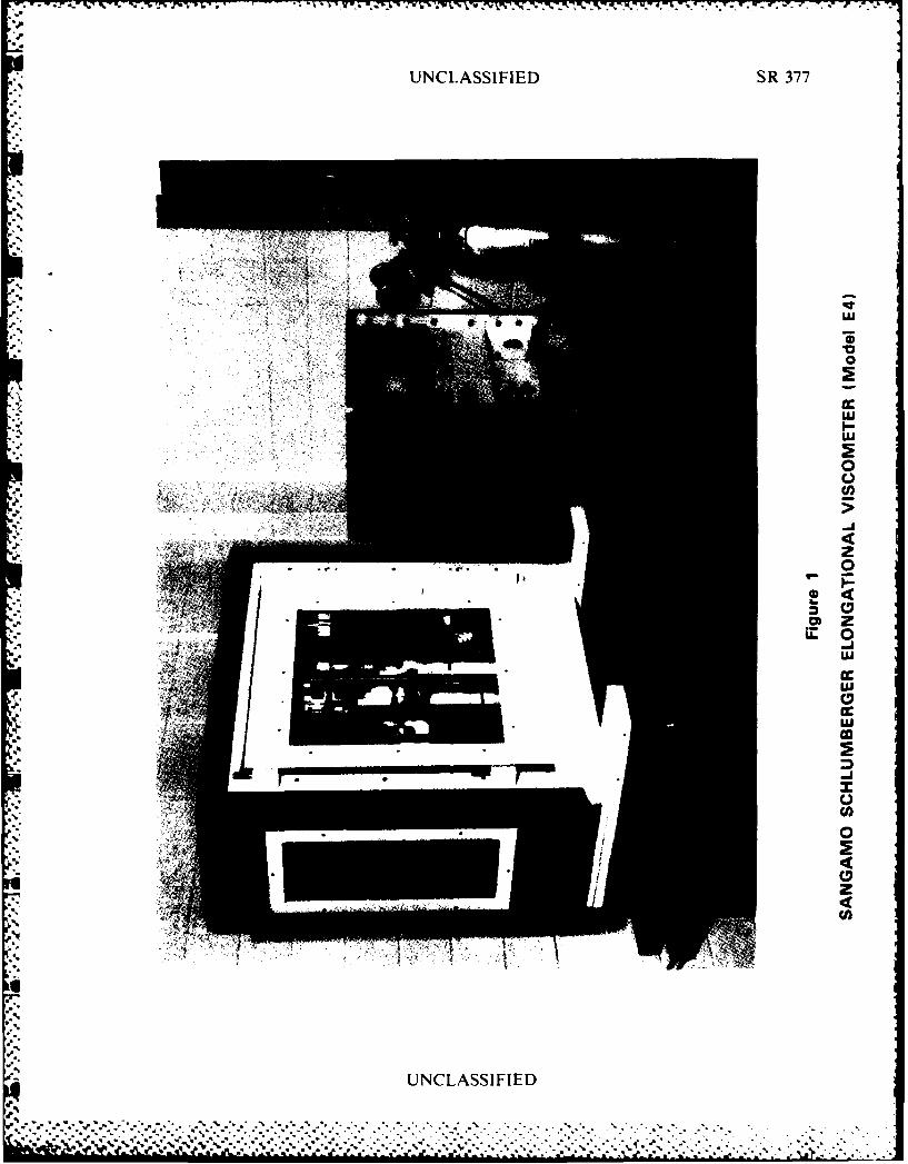
1. Sangamo Schlumberger Elongational Viscometer (Model E4)
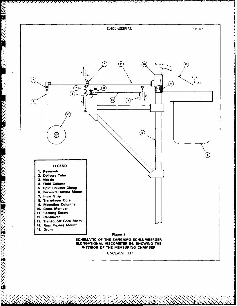
2. Schematic of the Sangamo Schlumberger Elongational Viscometer E4, Showing the
Interior of the Measuring Chamber
3. Elongational Load vs Time for Golden Shell 50 Oil Before Modification of the
Viscometer
4. Overall and Detailed View of Weights Placed on Top of the Fluid Reservoir
5. Elongational Load as a Function of Weight Loss
6. View of the Modified Measuring Chamber, Showing the Side Mounting of the FluidReservoir
7. Elongational Load vs Time for Golden Shell 50 Oil After Modification of theViscometer
8. Detail of the Safety Clamp Assembly for the Delivery Tube
9. Typical Photograph of the Fluid Column, Using a 35 mm SLR Camera with a
200 mm Micro-Nikkor Lens, and a 200 W • s Flash
UNCLASSIFIED
. . . . .
UNCLASSIFIED
LIST OF FIGURES IN APPENDIX II
II- 1 Detail of the Reservoir Relocation
11-2 Drawing of the Reservoir Clamp
II- 3 Drawing of the Adaptor Plate
II- 4 Drawing of the Stainless Steel Flange and the Teflon Gasket
11- 5 Drawing of the Safety Clamp
U
9
UNCLASSIFIED
' + T" " " - 'C " "- $ ' ' ' *+" . .. - ... ... . .° *.,-*r+.',** .. *. **, . .... . .,.- -,.,, ,. , ..,
- I I iI+ I + I !
UNCLASSIFIED
DEFENCE RESEARCH ESTABLISHMENT SUFFIELD-€ RALSTON ALBERTA
SUFFIELD REPORT NO. 377
MEASUREMENTS OF ELONGATIONAL VISCOMETRY USING
A FIBER SPINNING TECHNIQUE
PART I: MODIFICATIONS TO THE SANGAMO SCHLUMBERGERELONGATIONAL VISCOMETER MODEL E4 (U)
by
M.D. Gauthier Mayer, W.J. Fenrick and S.J. Armour
INTRODUCTION
1. As part of its continuing study of methods of characterizing polymer solutions andof identifying the parameters important in the aerodynamic breakup of polymer
solutions, the rheology group at the Defence Research Establishment Suffield (DRES)has undertaken a detailed study of the methods of measuring elongational viscosity.Three methods of measuring elongational viscosity (I) which were deemed to warrantdetailed investigation were fiber spinning (2,3,4), Fano or syphon flow (5,6,7) andflow through porous media and/or convergent chanfiels (8, 9). Of these methods, thatof fiber spinning was considered to show the most promise as it was the bestdocumented (2,3,4) and as a commercial fiber spinning device, the Sangamo
aUNCLASSIFIED
4
. .- - -* t. ' C . *. ., .* • " , . . • . W . q . -S ttb _. 1 . in a %t " . . _ - • . * 'I' - -- .

UNCLASSIFIED /2
Schlumberger Elongational Viscometer, was readily available. The other two methodswould have required the design and construction of reasonably complicatedinstrumentation and the development of the associated software, both of which arerelatively time consuming and labor intensive processes. Consequently, DRESpurchased an Elongational Viscometer (Model E4) from Sangamo Schlumberger andhad it commissioned by the Sangamo service representative, Mr. Roy Spooner onJuly 5, 1983.
2. As part of the purchase arrangement, the authors agreed to undertake a detailedevaluation of the viscometer and report to Sangamo any shortcomings discovered. Thepresent report is a description of the tests undertaken, the problems encountered and themodifications made to the Sangamo Schlumberger Elongational Viscometer in order torender it capable of measuring the elongational viscosity of polymer solutions havingzero shear viscosities in the range 1 to 100 poise. It is hoped that it will be of assistance toSangamo in the manufacture of additional viscometers and the modifications of existentones.
DESCRIPTION OF THE VISCOMETER
3. The Sangamo Schlumberger Elongational Viscometer is a fiber spinning devicebased on the design of Ferguson (4). The viscometer, which consists of a measuringchamber and a control unit, is shown in Figure l and described in the company literatureincluded as Appendix I.
4. The operation of the viscometer can be briefly described as follows (see Figure 2).The viscometer is prepared for a run by first calibrating the transducer assembly for therange to be used during the run. The fluid whose viscosity is to be measured is placed inthe fluid reservoir (No. 1) and the reservoir is pressurized slowly with compressed gas sothat the delivery tube (No. 2) gradually fills with fluid. (Gradual filling is necessary toprevent the formation of bubbles in the line.) Once the fluid exits the nozzle (No. 3)uniformly, the nozzle is capped with a small circular piece of paper and the compressedgas is shut off. The piece of paper is held in place by atmospheric pressure, as the tubetries to drain back into the reservoir, and ensures that the delivery tube is completelyfilled with fluid. The elongational load is zeroed by adjusting the transducer coil positionfor gro' adjustments and the zero control for fine adjustments. A weight correspondingto th ,esired full scale reading (1 g for the 100 range; 250 mg for the 25 range) is placed
UNCLASSIFIED
~~~~~ % %@ %4~.~-..€....-.,..- .. ,.:,.,€..,.:...-,:.- ----..-- ,,., ..-..... -... .... ,.-. .....f.....V. . .. , .-r % %, . .'. '-'.'- L ••.' "- " ' ' ''' '""' .'."--' "'' ' . -" " " " " " " """"-.' -:'"•-' . ': .X ' kz v'sk-'. '
UNCLASSIFIED /3
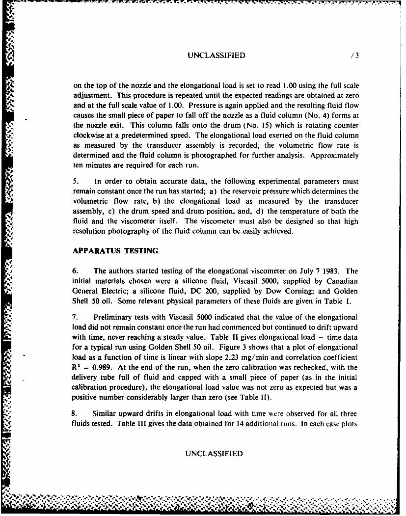
on the top of the nozzle and the elongational load is set to read 1.00 using the full scaleadjustment. This procedure is repeated until the expected readings are obtained at zeroand at the full scale value of 1.00. Pressure is again applied and the resulting fluid flowcauses the small piece of paper to fall off the nozzle as a fluid column (No. 4) forms atthe nozzle exit. This column falls onto the drum (No. 15) which is rotating counterclockwise at a predetermined speed. The elongational load exerted on the fluid columnas measured by the transducer assembly is recorded, the volumetric flow rate isdetermined and the fluid column is photographed for further analysis. Approximatelyten minutes are required for each run.
5. In order to obtain accurate data, the following experimental parameters mustremain constant once the run has started; a) the reservoir pressure which determines thevolumetric flow rate, b) the elongational load as measured by the transducerassembly, c) the drum speed and drum position, and, d) the temperature of both thefluid and the viscometer itself. The viscometer must also be designed so that highresolution photography of the fluid column can be easily achieved.
APPARATUS TESTING
6. The authors started testing of the elongational viscometer on July 7 1983. Theinitial materials chosen were a silicone fluid, Viscasil 5000, supplied by CanadianGeneral Electric; a silicone fluid, DC 200, supplied by Dow Corning; and GoldenShell 50 oil. Some relevant physical parameters of these fluids are given in Table 1.
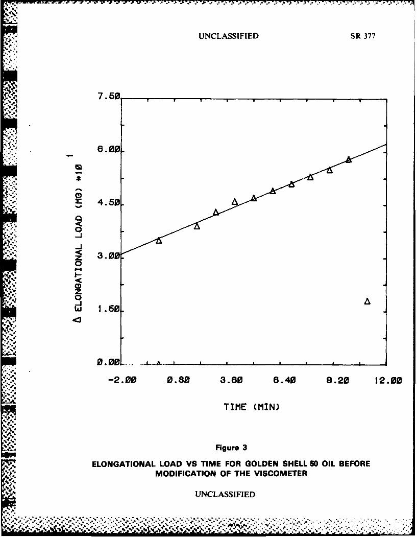
7. Preliminary tests with Viscasil 5000 indicated that the value of the elongationalload did not remain constant once the run had commenced but continued to drift upwardwith time, never reaching a steady value. Table II gives elongational load - time datafor a typical run using Golden Shell 50 oil. Figure 3 shows that a plot of elongational
load as a function of time is linear with slope 2.23 mg/min and correlation coefficientR2 = 0.989. At the end of the run, when the zero calibration was rechecked, with thedelivery tube full of fluid and capped with a small piece of paper (as in the initialcalibration procedure), the elongational load value was not zero as expected but was apositive number considerably larger than zero (see Table I).
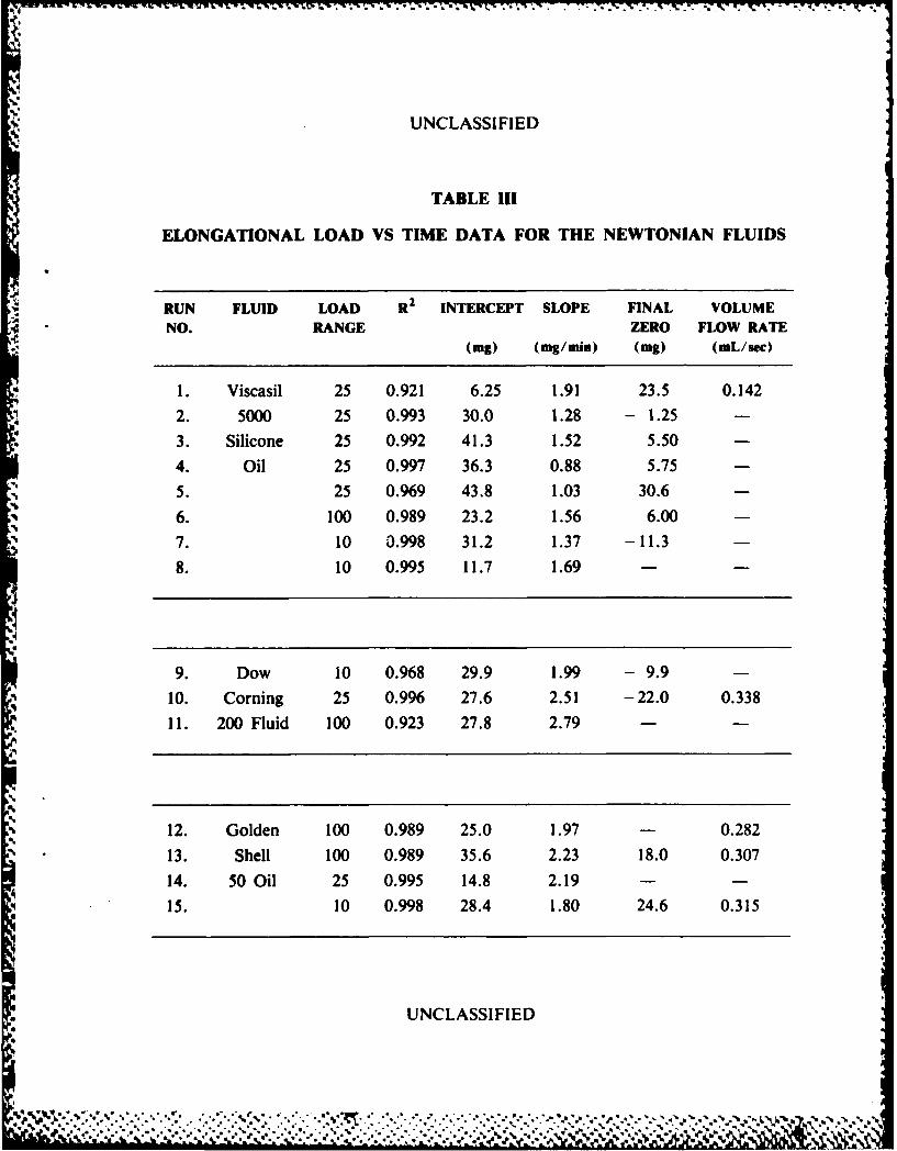
8. Similar upward drifts in elongational load with time were observed for all threefluids tested. Table Ill gives the data obtained for 14 additional runs. In each case plots
UNCLASSIFIED
/.
*. " -. ." " .% " " - a• " . -% -S. S " * 1. " '.% "'' . % " . " . "." . " " . - " . %J
UNCLASSIFIED "14
of elongational load as a function of time were linear with the elongation load value notnormally returning to zero at the end of the run. The numerical value of the slope,although not constant, changed over a relatively narrow range (0.88 - 2.79 mg/ min).This observation coupled with the fact that the upward drift was observed for fluids ofwidely different viscosity and different density, implied that the drift was more likely anartifact of the measuring system than of the fluid used.
9. Possible causes of this increase in elongational load were:
a. variable volumetric flow rate during a run
b. variable drum speed
c. varying chamber and/or fluid temperature
d. bubbles in the fluid
e. incorrect alignment of the delivery tube - transducer assembly
f. electronic drift in the elongation load measuring assembly
Possibility (a) was ruled out as the volumetric flow rate, was determined at the start,middle and end of several runs (see Table III) and found to be constant during anyparticular run. Possibility (b) was also ruled out as the drift continued even when thefluid fell onto a stationary drum. Checks of the drum speed with a strobe light alsoindicated that it was constant. The temperature of the chamber was recorded duringeach run and found to vary less than 0.2°C during the course of a run. The fluidtemperature in the reservoir was also monitored and found to be constant. Theoccurrence of bubbles in the fluid was also ruled out as a major factor as there was noevidence of bubbles in the fluid issuing from the nozzle once the run had commenced. Itwas also considered highly unlikely that a random occurrence such as bubble formationwould lead to a systematic increase in elongational load with a variety of fluids and a(several different operating pressures.
10. The possibility of incorrect alignment of the delivery tube-transducer assemblywas examined in detail. The complete assembly was carefully reassembled and alignedusing a cathetometer and the transducer was checked to make certain that the core wascentered and free to move. The assembly was then carefully tightened down so that noslippage would occur during the run and the alignment rechecked. This operation had noeffect on the elongation load, which still continued to drift upward with time.
UNCLASSIFIED
.4
,.
UNCLASSIFIED /5
11. The possibility of electronic drift in the elongational load measuring system wasruled out as the zero value of the elongational load did not drift appreciably with time.The possibility of a faulty amplification stage was also ruled out as the upward drift wasobserved on three different amplification ranges (100, 25 and 10 ranges).
12. The above considerations necessitated a detailed analysis of the mechanics of themeasurement system (see Figure 2). When pressure was applied to the reservoir (No. 1),the fluid left the reservoir, passed along the delivery tube (No. 2) and formed a column(No. 4) at the exit of the nozzle (No. 3). The fluid column then fell onto the drum(No. 15). The added weight of the fluid column (No. 4) caused the nozzle to movedc -,nward. The downward movement of the nozzle resulted in downward movement,B2, of the split column clamp (No. 5) which was transferred to the forward flexuremount hinge assembly (No. 6) by the Invar strip (No. 7) allowing downward movement,C2, of the mount (No. 6). This downward movement, C2 , resulted in a greatly amplifiedupward movement of the transducer core (No. 8) in the direction D.The amplification factor between movement, C2 , and D2 was determined to beapproximately 10 to 1. The above analysis implied that if the apparatus was operating asexpected, the weight of the fluid column would have been the only cause of the upwardmovement D2 and the elongational load value should have remained constant once thefluid column had been established. Since the elongation load value did not remainconstant but continued to drift upward with time, an additional factor, other than theweight of the fluid column, must have contributed to upward movement at D2.
13. Further examination of the apparatus provided the answer. The main mountingcolumns (No. 9) had been machined down at the top to a diameter of approximately0.4 inches so that they could be fitted into the upper cross member (No. 10) which waslocked to the smaller portion of the column (No. 9) by the locking screws (No. 11).When the reservoir (No. 1) was filled with 500 grams of fluid and suspended from thecantilever mount (No. 12) the machined down portion of the mounting columns (No. 9)flexed backwards, as indicated by the arrow F. This backward flexing allowed thereservoir (No. 1) and cantilever mount (No. 12) to move downward as indicated by A.This downward motion at A resulted in an upward motion at B of twice the magnitudeof that at A. Upward motion at B was directly transferred to C which in turn causedmovement at D of 10 times the magnitude of that at C. If Figure 2 is examined, it isapparent that movement at A would result in a 20 fold movement at D. Therefore, ifmovement at A was 0.0001 inches the resulting movement at D would be 0.002 inches.Tests have shown that movement at D of only 0.001 inch will cause the elongationalload to change by 30 mg (30 percent of the full scale value on the 10 range).
UNCLASSIFIED
Pa"% .e-. "o. "..- -.

UNCLASSIFIED /6
14. With the above analysis in mind the movements which occur during an actual run
were considered. At the start of a run, the reservoir was filled with approximately
500 grams of fluid and suspended from the cantilever mount (No. 12) causing
downward motion A. When pressure was applied to the reservoir, the fluid flowed
along the delivery tube and out of the nozzle, forming the fluid column. Since thevolumetric flow rate was constant throughout the experiment the reservoir was slowly
emptied at a constant rate. As the reservoir was emptied, weight, in the form of fluid,
was removed from it and the reservoir became lighter allowing the small section of the
main column (No. 9) to recover from flexing by moving in the direction F,. Slow steady
* upward movement at A then resulted in slow steady downward movement at B, and C,which in turn caused slow steady upward movement at D. Thus it appeared that the
removal of fluid from the reservoir caused the steady upward drift in elongational load
with time.
15. This hypothesis was verified by the following experiment in which the removal of
fluid from the reservoir during a run was simulated by the removal of weights placed on
the top of the reservoir. The reservoir and delivery tube were emptied of fluid and a total
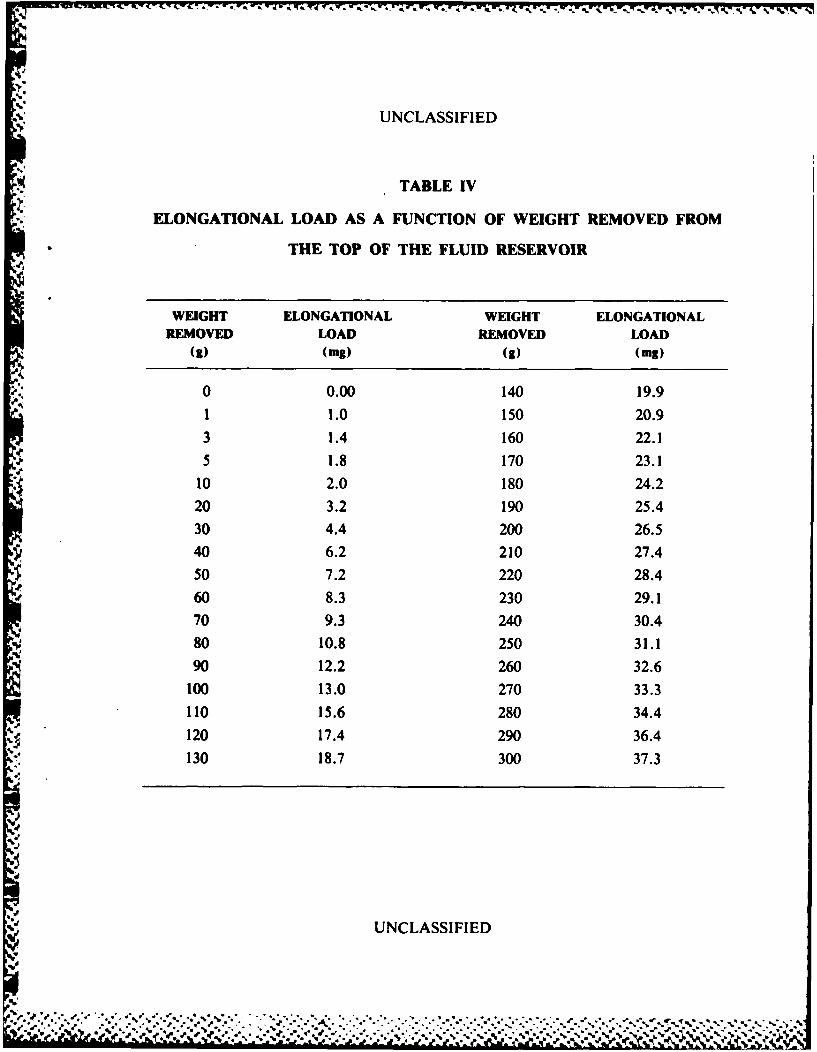
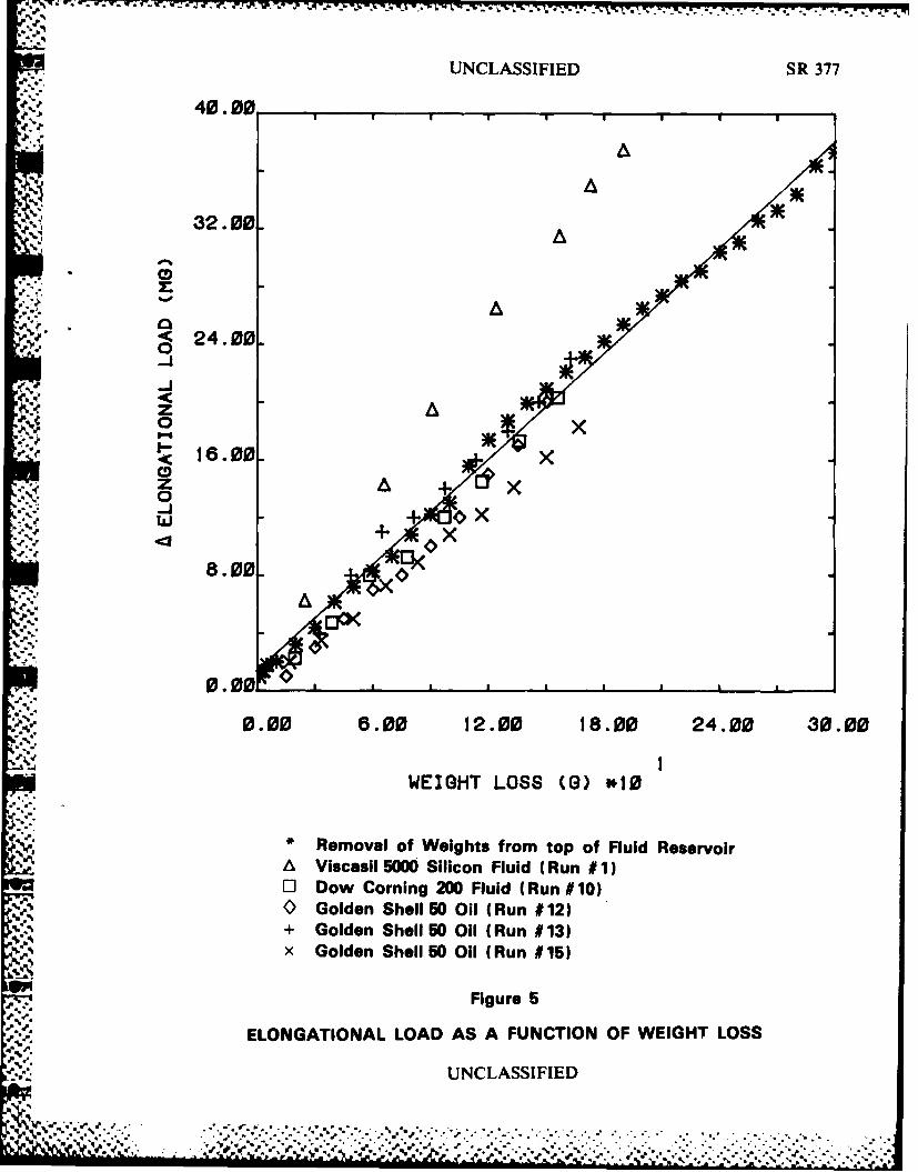
of 300 grams was placed on the top of the reservoir as shown in Figure 4. Theelongational load was then zeroed. The weight was removed 10 grams at a time and thevalue of the elongational load recorded until all 300 grams had been removed. The data
obtained is recorded in Table IV. Figure 5 shows a plot of elongational load as afunction of weight removed. Although the data is not perfectly linear, there is a steady
increase in elongational load as the weight is removed from the reservoir.
16. As a further verification, the data obtained in previous attempts to measure
elongational viscosity was reduced to this form, by using the volumetric flow rate and
fluid density to calculate the weight loss. Elongational load as a function of weight loss
for runs 1, 10, 12, 13 and 15 of Table III was then plotted on Figure 5. The data from
the weight removal experiment lies in the center of the narrow band of data obtained in
the viscosity experiments.
17. Consequently, the hypothesis that the upward drift in elongational load was
caused by the removal of fluid from the reservoir and the resultant straightening of the
columns (No. 9) was verified.
UNCLASSIFIED
%. % .

UNCLASSIFIED /7
DESIGN MODIFICATIONS
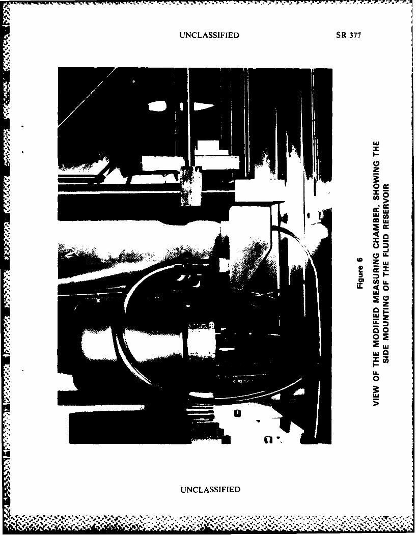
18. To correct this situation the reservoir was removed from the cantilever andmounted on the inner wall of the chamber surrounding the apparatus as shown inFigure 6 and Appendix 1I-1. A specially designed clamp (Appendix II-1, No. 6) wasmanufacturered to fit the upper portion of the reservoir (No. 5). This clamp wasattached to an adaptor plate (No. 2) which was designed to fasten to the inner wall of thechamber (No. 1) using 4 existing screws (No. 3). A stainless steel flange (No. 7) wasalso manufactured which, when fitted to the top of the reservoir using the existing bolthole pattern, not only sealed the reservoir but also allowed a 3/8 inch diameter stainlessii steel tube (No. 10) to pass through its center. A standard 3/8 inch Swagelok® fitting(No. 9) was drilled through and the center hole in the bolt hole pattern was enlarged to7/16 inch to allow the tube to enter the reservoir. This stainless steel tube emerged fromthe top of the reservoir and was connected to the barbed hose insert (No. 13) by a lengthof 5/16 inch ID Tygon® pressure tubing (No. 12). Tygon® tubing was used because itis both flexible and transparent. Flexibility prevents the transfer of vibrations from theenclosure to the transducer assembly. Such vibrations could cause the transducer beamto resonate. Transparency permits monitoring of the fluid and the detection of anybubbles entrained in it. Since the viscometer would be used to test solutions known toundergo gelation if subject to high shearing stresses upstream of the nozzle, it wasdecided to eliminate any small diameter tubing in the fluid supply line between thereservoir (No. 4) and the delivery tube (No. 20). Consequently, the original 1/8 inchstainless steel supply tube was removed from the cantilever and a 1/4 inch N.P.T. tappedhole provided to accept the barbed hose insert (No. 13). In addition, the depth of thetap drill hole for the 3/8 inch B.S.P. thread in the front of the cantilever (No. 14) wasextended until it reached the tap drill hole used for the 1/4 inch N.P.T. hole provided forthe barbed hose insert. These modifications to the cantilever mount provided a supplyline free of restrictions up to the B.S.P. fitting (No. 17). The B.S.P. fitting has arestriction incorporated into its design which reduces the duct to a diameter of0.089 inches just prior to the entrance into the delivery tube (No. 20). The pressuretransducer supplied with the apparatus is located in the electronics module of the system.For the experiments with the gelling solutions, the pressure is monitored just prior to theentrance to the delivery tube as this is the point closest to the nozzle where a transducercan be easily installed. To facilitate this measurement a 1/2 inch x 20 T.P.I. N.F. holewas provided in the top of the cantilever (No. 14) to accommodate a Bytrex PressureTransducer (No. 15).
UNCLASSIFIED
Se.

UNCLASSIFIED /8
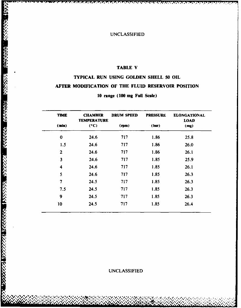
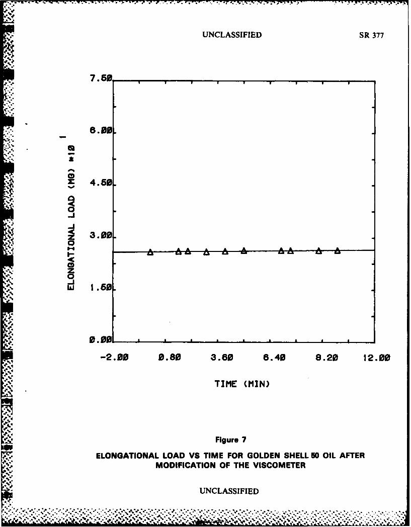
19. Since the completion of these modifications, the elongational load value has
stopped drifting and remains essentially constant throughout the run. Table V gives
elongation load - time data for a representative run using Golden Shell 50 oil. Figure 7
shows a plot of elongational load as a function of time for the data of Table V.Comparison of Figure 3, a typical run before modification, and Figure 7, a typical run
after modification, graphically illustrates that the modification has permitted the
achievement of a steady value for the elongational load.
20. Details of the components required for this modification are given in
Appendix II.
21. Attention was now directed toward the design of a safety clamp for the
transducer assembly and to methods of measuring the fluid column.
22. Since the alignment of the delivery tube-transducer assembly is quite time
consuming and since the Invar strips and the hinge assembly are very easily damaged, asafety clamp was designed to facilitate the changing of the nozzle. This clamp which is
shown in Figure 8 and illustrated in Appendix 11-5 is described as follows. Themounting bracket (Appendix 11-5 No. I) was designed to attach to two existing screws
originally intended to hold the retaining frame for the glass in the top of the chamber.
The remainder of the clamp assembly rotates about the axis A-A to allow it to beretracted when not required. The length of the unit B is fixed and is arranged so that inthe down position the jaws (No. 4) are located on either side of the nozzle. When the
hand wheel (No. 2) is moved downward on the thread of the support (No. 3) the tapered
portion of the wheel contacts the upper portion of the holding jaws (No. 4) forcing bothoutward. The forward portions of the clamping jaws are simultaneously forced inwardapproaching the nozzle from either side. This system allows the nozzle to be clamped
firmly with little or no displacement. When the hand wheel is moved upwards two
springs (No. 5) force the holding jaws away from the nozzle so that the clamp assembly
does not touch the nozzle during retraction. Using this safety clamp the nozzle could be
easily changed without damaging the Invar strip or hinge assembly and without changingthe alignment of the delivery tube.
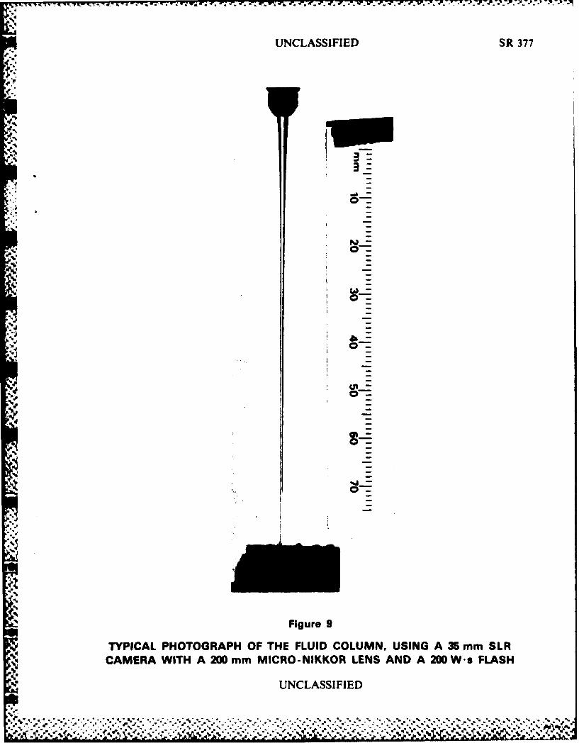
23. The fluid column (see Figure 2, No. 4 and Figure 9) can be analyzed either bymeasuring its diameter as a function of length during the run using a cathetometer or byphotographing the column (4). Analysis during the run using the cathetometer was not
UNCLASSIFIED
""' .,5 .. ~,. 6, ?;: : : . ...... ,. .... ,,-%..o. .,.,....,..-.. ... .. ,. ..

4
UNCLASSIFIED /9
regarded as practical because of the long time required to take a sufficient number ofdata points to accurately define the fluid column. Any minor motions or fluctuations inthe column would produce substantial errors in the measurements. This method also has
the major disadvantage of not giving a permanent record of the column profile.
24. Photography has the dual advantage of giving a permanent record of the columnprofile at a particular instant in time and of requiring only a short period of time to takeseveral exposures. Since the fluid column could most easily be viewed through theinsulating door on the left hand side of the measuring chamber (see Figure 1) it wasdecided to photograph through this door. The enclosure was modified for photographyin the following manner. A scale was positioned in the same plane as the fluid stream in
order to provide a calibration for the photographs. The main door on the front of thechamber was covered with drafting paper to act as a diffuser for the flash. Strips ofwhite cardboard were placed directly behind the fluid column at the side opposite the
flash and on the inside of the main door to deflect the flash and illuminate the fluid
column. Since the present experimcnts were conducted at room temperature it waspossible to remove the left inside window leaving the outer, insulating door to close the
chamber. This window is often splashed by fluid thrown off the drum and must becleaned after each run, an operation which is difficult to do without disturbing the
delivery tube assembly. The outer insulating door, however, opens allowing easy accessfor cleaning.
25. The equipment used consisted of a Nikon 35 mm SLR camera fitted with a200 mm micro-Nikkor lens and equipped with a 200 W • s flash. A typical photographobtained with this system is shown in Figure 9.
SUMMARY AND CONCLUSIONS
26. Preliminary evaluation of the Sangamo Schlumberger Elongational Viscometer
E4 showed that the viscometer, as delivered by the manufacturer, could not be used toaccurately measure the elongational viscosity of fluids having zero shear viscosities in therange 1 to 100 poise.
27. The principal problem with the viscometer was the fact that the value of the
elongational load, which should remain constant once a measurement has started,continued to drift upward with time, never reaching a steady value.
UNCLASSIFIED

UNCLASSIFIED /10
28. The cause of this upward drift was the fluid delivery system; specifically, themethod of coupling the fluid reservoir to the delivery tube-transducer assembly.
29. A new fluid delivery system was designed which eliminated this problem. Details
of its construction are supplied so that other users of the Sangamo SchlumbergerElongational Viscometer can make the same modification.
30. The Sangamo Schlumberger Elongational Viscometer with the modificationsmade by the authors appears to be capable of accurately measuring the elongationalviscosity of a variety of fluids.
31. The measurement of elongational viscosity of polymer solutions of interest to
DND using this instrument is currently underway and will be the subject of part two ofthis report.
i UNCLASSIFIED
#0-V
1o~l- ,.°. % % '. , %. , , " " ," .'"% '°" .""% - ,""""""" - -*'"°'% " °'o "" - *" "- ' ' -
.1' • , ",' . ..',.. . ".. " . " .. ' + " . - " .. " . , " . -. . , . .,- . - .'- .'- . .. .
* ,8 +,. .,+ ,,+ ,,r.r .,+ . ,-,,'q+ - r,, ,.+ ;.r l ,+,,p . + ,.-, ,_,.., ,- r . ¢ + . € ,€,.,,++,e. " ., - . .-. ,' h11i+ l
UNCLASSIFIED /1
REFERENCES
1. C.J.S. Petrie, "Elongational Flows", Putman (London) 1979.
2. K.M. Baid and A.B. Metzner, "Rheological Properties of Dilute PolymerSolutions Determined in Extensional and Shearing Experiments", Trans. Soc.Rheol. 22 pp. 237 - 260 (1977).
3. P.K. Agarwal, W.K. Lee, J.M. Lornston, C.I. Richardson, K.F. Wissbrun andA.B. Metzner, "Rheological Behaviour of Molten Polymers in Shearing andExtensional Flows", Trans. Soc. Rheol. 21 pp. 355 - 379 (1977).
4. J. Ferguson and N.E. Hudson, "A New Viscometer for the Measurement ofApparent Elongational Viscosity", J. Phys. E. 8 pp. 526 - 530 (1975).
5. F.A. Kanel, "The extension of viscoelastic materials", Ph.D. Dissertation,University of Delaware (1972).
6. S.T.J. Peng and R.F. Landel, "Preliminary Investigation of Elongational Flow ofDilute Polymer Solutions", J. Appl. Phys. 47 pp. 4255 - 4260 (1976).
7. W.C. MacSporran, "On the Suspended Syphon Elongational Rheometer", J.Non Newtonian Fluid Mech. 8 pp. 119 - 138 (1981).
8. R.J. Marshall and A.B. Metzner, "Flow of Viscoelastic Fluids through PorousMedia", Ind. Eng. Chem. Fund. 6 pp. 393 - 400 (1967).
n 9. D.F. James and D.R. McLaren, "The Laminar Flow of Dilute Polymer Solutionsthrough Porous Media", J. Fluid Mech. 70 pp. 733 - 752 (1975).
.
UNCLASSIFIED
,. .,.
• " "" " " " " " " " -I* ,, I •% % • % - a " , ' ."

UNCLASSIFIED
TABLE I
RELEVANT PHYSICAL PROPERTIES OF
THE NEWTONIAN FLUIDS TESTED
DENSITY (g/mL) VISCOSITY (poise)@ 250 C @ 250 C
Viscasil 5000Silicone Fluid 0.9702 72.6
Lot BJ 108
Dow Corning200 0.9657 1.96
Lot AA6659
Golden Shell
50 Oil 0.882 5.2
427-005-37
UNCLASSIFIED
s, *%.lk ',r e"d' % %-,' ' J-o . " .v , *..°; o o*. y.. ..% .°," o' .- .. * * .. .. .. - * .'. . . .-. . . . - * . .* .o . ,,
UNCLASSIFIED
TABLE I
TYPICAL DATA FOR GOLDEN SHELL 50 OIL
BEFORE MODIFICATION OF THE VISCOMETER
100 range (1000 mg Full Scale)
TIME CHAMBER DRUM SPEED PRESSURE ELONGATIONALN TEMPERATURE LOAD
(ain) (0C) (rpm) (bar) (mg)
Zero
calibration 24.0 0.00
0 24.0 701 0.52 352 24.0 702 0.57 39
3 24.0 702 0.56 434 24.0 702 0.56 46
5 24.0 702 0.57 47
6 24.0 702 0.57 49
7 24.1 702 0.57 518 24.1 702 0.57 53
9 24.1 702 0.57 5510 24.1 702 0.57 58
zero 24.1 18I; calibration
check
U LSF
UNCLASSIFIED
if. °
to V .. " > .. :v t ' " * " - * * • • o . • . .. % .. . . . * • • . . . . . .-. .
m .. • e- ° o 9- °- * . , ." - . . . •- .* °. ." . , ° . . . • .* °. .- ,, - • .* . . o °. ° . . . . .... .
UNCLASSIFIED
TABLE III
ELONGATIONAL LOAD VS TIME DATA FOR THE NEWTONIAN FLUIDS
RUN FLUID LOAD R2 INTERCEPT SLOPE FINAL VOLUME
NO. RANGE ZERO FLOW RATE(mg) (mg/min) (ug) (mL/see)
1. Viscasil 25 0.921 6.25 1.91 23.5 0.142
2. 5000 25 0.993 30.0 1.28 - 1.25 -
3. Silicone 25 0.992 41.3 1.52 5.50 -
4. Oil 25 0.997 36.3 0.88 5.75 -
5. 25 0.969 43.8 1.03 30.6 -
6. 100 0.989 23.2 1.56 6.00 -
7. 10 0.998 31.2 1.37 -11.3 -
8. 10 0.995 11.7 1.69 - -
9. Dow 10 0.968 29.9 1.99 - 9.9 -
10. Corning 25 0.996 27.6 2.51 -22.0 0.338
11. 200 Fluid 100 0.923 27.8 2.79 - -
12. Golden 100 0.989 25.0 1.97 - 0.28213. Shell 100 0.989 35.6 2.23 18.0 0.307
14. 50 Oil 25 0.995 14.8 2.19 - -
15. 10 0.998 28.4 1.80 24.6 0.315
UNCLASSIFIED
," €, .*.....*.-,.f.a ,..,. ,.*. .. .,...... ,.-.,-...... . . ,,-... .4.0 ., . % ,
S.m
UNCLASSIFIED
TABLE IV
ELONGATIONAL LOAD AS A FUNCTION OF WEIGHT REMOVED FROM
THE TOP OF THE FLUID RESERVOIR
WEIGHT ELONGATIONAL WEIGHT ELONGATIONALREMOVED LOAD REMOVED LOAD
(g) (.g) (g) (mg)
0 0.00 140 19.9
1 1.0 150 20.93 1.4 160 22.15 1.8 170 23.1
10 2.0 180 24.220 3.2 190 25.430 4.4 200 26.540 6.2 210 27.4
50 7.2 220 28.4
60 8.3 230 29.170 9.3 240 30.480 10.8 250 31.190 12.2 260 32.6100 13.0 270 33.3110 15.6 280 34.4
120 17.4 290 36.4130 18.7 300 37.3
aUNCLASSIFIED
• "...'.-'.-' ',-. ",. "..".,.......... .... . ....';.. .s ......................-........ n 1 . .% .
.
" UNCLASSIFIED
TABLE V
TYPICAL RUN USING GOLDEN SHELL 50 OIL
AFTER MODIFICATION OF THE FLUID RESERVOIR POSITION
10 range (100 mg Full Scale)
TIME CHAMBER DRUM SPEED PRESSURE ELONGATIONALTEMPERATURE LOAD
(min) (0C) (rpm) (bar) (mg)
0 24.6 717 1.86 25.8
1.5 24.6 717 1.86 26.0
2 24.6 717 1.86 26.1
3 24.6 717 1.85 25.94 24.6 717 1.85 26.1
5 24.6 717 1.85 26.3
7 24.5 717 1.85 26.3
7.5 24.5 717 1.85 26.3
9 24.5 717 1.85 26.3
10 24.5 717 1.85 26.4
UNCLASSIFIED
0-
.9."?.r2,'.' . 9 ,?,.?.'..'.",. .'-'.._._. . . . . .--- . , . .. , . . . . -, . -. -. -. . . . .
--. _.- "2"-" .-.- ',"."€"."-" ".","..'." . t..'-.'..-.' '-'.'. ', "-. - "- "-'-.'- '.,**.'-9. ..-. , '-'-.. '-'. '-'....-. .' .'
UNCLASSIFIED SR 377
S..'
s
0
UNCLASIFIE
UNCLASSIFIED SR 37'
10 F21
'10
1 /1
'4..3
'PAz
.515
2. Delivery Tube
*4. Fluid ColumnP4 5. Split Column Clamp
6. Forward Flexure Mount7. Invar Strip8. Transducer Core9. Mounting Columns
10. Cross Member11. Locking Screw
-\12. Cantilever'P.13. Transducer Core Beam
*'S -14. Rear Flexiure Mount15. Drum
Fg r
SCHEMATIC OF THE SANGAMO SCHLUMBERGERELONGATIONAL VISCOMETER E4, SHOWING THE
p INTERIOR OF THE MEASURING CHAMBER
UNCLASSIFIED
4./* .- UNCLASSIFIED SR 377
4t. .•
7.560
X:4.0
- 6.00.
0." 4.. 0
0
z-, 1.50.
~TIME (MIN)
' Figure 30ELONGATIONAL LOAD VS TIME FOR GOLDEN SHELL 60 OIL BEFORE
. MODIFICATION OF THE VISCOMETER
, UNCLASSIFIED
- mZ
-20 03
.'.. . .'.-.,,...., ,-....... . .. .-. ..,. .- -.. .-. ,. . ....-TIME ,,. ,. (...M. . . . . . .N). . . .
_ _ ' , , F i g u r e " , . - , " , P ,r - , • . . 3. . - . - , , .. , . . - , . . . . . . . . ,

UNCLASSIFIED SR 377
Figure 4
OVERALL AND DETAILED VIEW OF WEIGHTS PLACED ON TOP OFTHE FLUID RESERVOIR
UNCLASSIFIED
UNCLASSIFIED SR 377
40.00I..I"",,
32.00.
< 24.00.0--
A x16.00- A
+ x
8.00.
0.00 a
0.00 6.00 12.00 18.00 24.00 30.00
WEIGHT LOSS (G) *10
* Removal of Weights from top of Fluid ReservoirA Viscasil 5000 Silicon Fluid (Run # 1)* Dow Corning 200 Fluid (Run# 10)0 Golden Shell 50 Oil (Run #12)+ Golden Shell 50 Oil (Run #13)x Golden Shell 50 Oil (Run #15)
Figure 5
ELONGATIONAL LOAD AS A FUNCTION OF WEIGHT LOSS
UNCLASSIFIED
' . .A& .. . .. . . . . .
-7 .. . . . . . .
UNCLASSIFIED SR 377
.1j
0 ccx -cc,
>
cog
< I-
IL
*L 0
UNCLASSIFIED
%*5 %5S ** ~ ~ * * ~ S ~ .
MAX 1 ~5 P S.~~%.. 4 *.~.. . . . . . . . . . . . . . . . . ~ . . . .
UNCLASSIFIED SR 377
7.5,
8..0
3.0
:--,
0
0 .001
EI:OAL LAD AS TIM FO GODE SHL A 0 OI AFE
.:--
-I
w .8
i
i-2.00 0.80 3.60 6.40 8.20 12.00B
i TIME (MIN)
Figure 7
ELONGATIONAL LOAD VS TIME FOR GOLDEN SHELL 50 OIL AFTERMODIFICATION OF THE VISCOMETER
UNCLASSIFIED
= . - .. .2 - . .. , : ' . . . . . . . - . 5 5, . . . . . -, , . . . . . . . . . S. . . . . .. ... .. . . .
S .S .:.,:. ,,.. *. ., . . ...... .. ' . . *5*.:5: :.i.: :.: > :.: *.5. .: :

UNCLASSIFIED SR 377
FigureS8
DETAIL OF THE SAFETY CLAMP ASSEMBLY FOR THE DELIVERY TUBE
UNCLASSIFIED
'L qtLb St ."*** * * * * * * * * * * * * * *
UNCLASSIFIED SR 377
'Ale
Figure:
TYPIAL POTOGAPHOF TE FLID CLUM, USNG A35 m SL
CAMRA IT A 00 m ICR - IKORLNADA20WFAS
UNLSSFE
UNCLASSIFIED
-.
APPENDIX I*1
SANGAMO SCHLUMBERGER BROCHURE
ON
ELONGATIONAL VISCOMETER
UNLSSFE

* ~ ~ ~. ~.*' *~ ~ q .~4. .~ (@~* . 1r ffa i" (. ~ . .. * . -
UNCLASSIFIED
L
4.r
, mo
-Ione
no
sonm a5one
UNLSSFE
UNCLASSIFIED
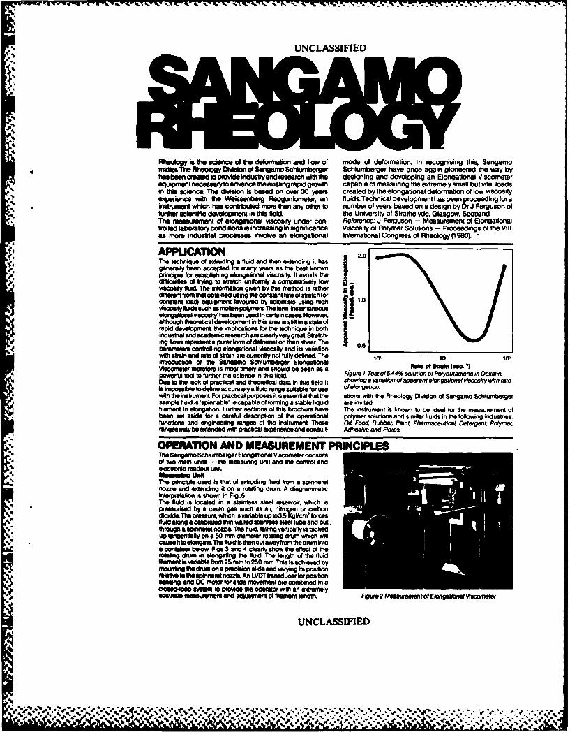
Rheology t the science of the dellormaion and flow of mode of deformation. In recognising this, Sangamomater. The Rlheology Division of Sangamo Schlumbeiger Schlumberger have once again pioneered the way byhasbeencr adloprovideindustryandreseerchwfthte designing and developing an Elongational Viscometereqtipont necesasaryto advance theeing rapid growth capable of measuring the extremely small but vital loadsin Ot science. The division is based on over 30 years created by the elongational deformation of low viscosityexperience with the Wseeiberg Reogoniometer, an fluids Technical developmenthas been proceedingforainstrument which has contributed more than any other to number of years based on a design by Dr J Ferguson offurter scienf development in this field, the University of Strathclyde, Glasgow, Scotland.The measurement of elongational viscosity under con, Reference: J Ferguson - Measurement of Elongationallled laboratory conditions is increasing in significance Viscosity of Polymer Solutions - Proceedings of the Vill
as more industrial procesm involve an elongational International Congress of Rheology (1980).
f APPL"CTIO 2.0The technique of extruding a fluid arid then exMending it hasgenerally been accepted for many years as the best knownprinciple for esablishing elongfional viscosity. It avoids thedifficulties of. tying to stretch uniformly a comparatively lowviscosity fluid The informatlion given by this method is ratherdifferent from that obtained using the constant rate of stretch (orconstant kx4 equipment favoured by scientists using high 11.0viscositytfuidssuch as molin polymers Thelerminstan ansouselongalonsl v=Wity' has been used In certain cases. However,although theoretical development in this area is still in a state ofrapid development, the implications for the lechnique in bothindustrial and academic research are cleartlyverygreat Stretch-ing flows represet purer form of deformation than shear. The 05parameters controlling elongational viscosity and its variation _ _ __1
with strain and rate of strain are currently not fully defined The 100 101 102introduction of the Sangamo Schlumberger ElongationalViscomete therefore is most timely and should be seen as a ph" of ee I..WO)powerful tool to further the science in this field Figure I Test of 6.44% solution of Polybutadiene in DekalittDue to the lack of practical and theoretical data in this field it showing a variation of apparent elongational viscosity with rateIs Imlposible to define accurately a fluid range suitable for use of elongationwith the instrument For practical purposes it is essential that the ations with the Rheology Division of Sangamo Schlumbergersample fluid is 'spinnable' ie capable of forming a stable liquid are invitedfilament in elongation. Further sections of this brochure have The instrument is known to be ideal for the measurement ofbeen set aside for a careful description of the operational polymer solutions and similar fluids in the following industries:functions and engineering ranges of the instrument These Oi Food Rubber; Paint Pharmaceutic Detergent Polymerranges maybe extended with practical experience and consult- Adhesive and Fibres
OPERATION AND MEASUREMENT PRINCIPLESThe Sangamo Schluntberger Elongatlonall Viscomreter consistsof two main units - the measuring unit and the control andelectronic readout unit
aI U. '. uMThe pr nciple used is that of extrding fluid Irom a spinneretnozzle and exeding it on a rotating drum A diagrammaticinterpretation is shown in Fig..5.The fluid is located in a stainless steel reservoir, which ispresaurised by a clean gas such as air, nitrogen or carbondioxide The pressure, which is variable up 1o3.5 Kgf/cm' forcesfluid along a calibrated thin walled stainless steel tube and out.
V Itough a spinneret nozzle. The fluid failing vertically is pickedup tangentially on a 50 mm diameter rotating drum which willcause it tolongalle. The fluid is then cut awayfrom the drum intoa container below. Figs 3 and 4 clearly show the effect of therotating drum in elongating the fluid. The length of the fluidfilamet Is varlble from 25 mm to 250 mm This is achieved bymouINg the drum an a precislon slide and varying Its positionrelative to te plnnert nozzle. An LVDT trnsducer for positionasnefin and DC motlor for side movement are combined In acfsed-loop aystem to provide the operator with an extremelyaccurate measurement and adluslnent of filament length. Figur 2 MeumentofElogaftill Viscometer
UNCLASSIFIED
-- %

UNCLASSIFIJ r)
,. . J
! .
Figure 3 F uider free fl Ihomnnewt with drum static Figure 4 Fluid in elongetion with drum rotating
The force generated is measured by the deflection of the thin the flow line can be determined. Alternatively this can be donewalled tube through which the fluid passes. The deflection is photographically.Theenvironmental chamberhasglass panelstransferred through an invar stnp, mechanically amplified via a to facilitate such measurements and mounting brackets arecrossed strip hinge, and measured by a frictionless LVDT providedtransducer. The entire assembly has been designed for stability Co" and fm t eroye Readut UnItwith mechanical stops to avoid overload damage. A range of This is housed in a single console for bench mounting andtube wall thicknesses are available to obtain maximum sensi- easyoperation.The panelis sub-dividedintosections concern-tavty for any given fluid. The associated transducer amplifier ing various operating modes. of the measuring unit Directotfersa400:1 rangeexpansion andelongational load measure- readings are provided in digital form with associated voltagement down to 1 milligram is easily obtainable. Mechanical outputs available for external recording.dmplng is carried out by means of a paddle retained within Reservoir Pressure: An indication of sufficient line pressure issilicon oil An electronic filter is incorporated with nine instantly provided together with a direct reading of reservoir pressure inselectable cut off frequencies ranging from 2.5 HZ to 100 Hz. Kgf/cm 2 with associated adjustmentCalibration is very simple, weights being placed immediately Chamber Controls:. three term controller with pr-set tmper-above the spinneret nozzle and electronic adjustments made ar Controlsd.diretr orseroire-st temper
accordingly. The simplicity of this operation allows calibration at atur control and direct reading of reservoir (fluidi temperatur.
any temperature level, thus avoiding concern over instrument Elongational Load: Direct reading of elongational load isoewtcwts. provided up to 1 gramme with range expansion for greater
The whole assembly is mounted on anti-vibration supports and sensitivity. Nine push button switches providea range of filteringhoused within an environmental chamber. Level adjustnent is from 25 Hz to 100 Hz to eliminate high frequency vibrations. Aprovided toensure vertical alignment of thefilamentto thedrum. section for the associated transducer calibration is included.A powerful electric hosting element is housed within the Drum Speed: Direct reading is provided for drum speed both inchamber and this is coupled to a three term controller. Circula- revs/minute ormetreasecond as selected. Push button controlstion is lan assisted. The system is capable of providing a areprovidedforfastandslowincreaseordecreaseinthespeedcontrolled temperature environment up to 100C. The sensing of rotation.element is mounted in the reservoir. Drum Position: Direct reading of the filament lngt in millimetresIt is neceseary to measure the diameter of the filament between is provided by measuring the drum position relative to thethe spinneret and the point of take-up on the drum. This is splnneret nozzle. Push button controls are provided for fast andnormallydone using a vertically travelling microscope or cathe- slow increase or decrease of the filament length. A section fortomeseraothat thediameterof the filamentat anydistancealong the associated transducer calibration is included
ANCILLARY EOUIPMENTA range of thin walled tubeo is available to maxmise sensitivity alternative muli-channel recorder can be used for continuouslywith any given fluid These are supplied threaded for easy monitoring of other parametersconnection to the reservoir and also for interchangeable Binary Coded Decimal (BCD) is available for all relevantsplnnert nozzles. functions thus providing outputs in digital form SangamoA range of spinneret nozzles is available with orifices from 03 Schlumberger will be pleased to provide technical advice onmm Io 2.0 mm diameter, interfacing with computer equipment.A sl le channel potentiornetric chart recorder is available for A camera or travelling microscope is available for the measure-dreCt connection to the elongational foed output signal. An ment of the filament deformation.
UNCLASSIFIED
NO' M .
%%
.:. " .'..' ."." . . .,.'-;'....-.' '.-.'" . . . .. . .... : : .. %:
: : :.:

UNCLASSIFIED
4-*1.'S ICFIATO I_________________________ Figure 5 Diagram of Sangamno
________________________________ - SchlumrbergWErintional VscometerMeasuring unit showng keycoirOenfts
I DrumSir 2 Slide
7 Reservoir9 Environmental C.. iamberI Anti-vbration feet
V Dimensions and weightsMeasuring Unit1000 rmwide 400 mm deep 725 mm high
r r Weight: 70 Kilogrammes
Control and Electronic Readout Unit(not illustrated)
-500 mm wide475 mm deep 725 mmg high
Weight: 50 Kilogrammes
Msaf'.nleelTemperature*Reservoir Environmental chamber with electric elements and fan circu-
Stainless steet construction - capacity 500 ml laltionFluid Piressure Three term temperature control from ambient to01 00*C monitoredInfinitely variable up to03.5 Kgt/cml by platinum resistance thermometer in reservoirSystem exhautsf to atmosphere at 4.22 Kgt'cm 2 FluidsReseivoir overload pressure capability of 2OKgf/cml These must be'spinnable' ie capable of forming a stable liquidEforigafional Load filament in elongationMeasuring range from 1 mg to 1000 mgA range of calibrated stainless steel tubes are available withvarying wall thicknesses - these provide maximum sensitivity Ee~fafor fluid under measurement Eet~Damping, mechanically by paddle in silicon fluid and electrically Mains Inputwith nine selectable ranges from2.5 Hz tol100 Hz 115 V or 230 Vac +10% -15%, 48to 65 Hz
Spinneret Nozzles ConsumptionStainless steel construction 1500 W maximumRange of orifice diameters: 0.3,05, 0.7, 1.0.1.5,2.0 mm OutputsFilamrent The following analogue voltage outputs can be made availableLength is infinitely variable from 25 to 250 mm for extemnal recording purposes. These are normally toea level ofDiameter is measured by travelling microscope or photograph- 1 V DC equivalent to the engineering units listed below (0.1 'Q___________________________ typical impedance). Outputs for Elongational Loadand FilamentDrum Length are available as standard. Binary Coded Decimal (BCD)Rotated byea closed loop drive system inf initely variable frm0- outputs are available as options.2000 reveiminue -equivalent to asurface speed from 0to 524 Fluid Pressure I Kgl/cm2
*me"reisecond Elongational Load 1 g, 025 g g.1 on selected range50 mm diameter stainless sleet as standard. Other surface Filamrent Length 250 mm, 100 mmnon selected rangematerials such as granite, ceramic, glaes etc are available Drum Speed 1000 rpm (rotatior#A cutler Is incorporated to remove fluid I metre/second (surface speed)iStrobioscope speed measuring facility Temperature 1 00t
SANGAMIO SCHLUMSERGERSAGA RHEOLOGY DMSION
N4ORTH OERSTED, BOGNOR REGISW SUSSEX P022 90S, ENGLAND6iTEL 024382501 TELEX:8862
ODsad by AiSIs Mubgig n i So Is CM EngWod
UNCLASSIFIED
% Ro
,, . • ... , . . . . . . . ... , ., . , . . . , . ,., . .. .. .. . . .:. .,, . . . ;- .,, 4, - , ,,.
UNCLASSIFIED
Ii
d'o
4-
.,
DRAWINGSNOFADSINIMDICAON
4.. ,,.,,,:.,.-,-. .-.. : .-. . . . , . . .. . . . . , . . . . . ., . • - , -, - . . . . . .
., ., ... .-... :..... ....... : .:.., ..: :...- : : .:.- ..:. .:. : :: .:-:.:.:.: .: : : *.: :, :.-.: .
. -:.., ::: ,:...,.. '...:, ;.:,.,-.< .::.. .;....,...4.z.:.:..:-. ;,, - - -.- .; .;. :.:
.
.5, UNCLASSIFIED
LEGEND, APPENDIX I-I
I. Inner Wall of Apparatus
2. Adaptor Plate
3. 8 x 36 UNF Socket Head Cap Screw
* 4. Reservoir
5. Reservoir Top
6. Reservoir Clamp
7. Stainless Steel Flange
8. Teflon® Gasket
9. Swagelok® Fitting (Drilled Through)
10. 3/8" O.D. Stainless Steel Tubing
11. Tridon Hose Clamps
12. 5/16" .D. Tygon® Pressure Tubing
13. Barbed Hose Insert
14. Cantilever Mount
15. Bytrex Pressure Transducer
16. Cross Member
17. (Fitting) 3/8" B.S.P. to 1/8" O.D. Tubing18. Mounting Column
19. 1/4 x 20 Socket Head Cap Screw
20. Delivery Tube
UNCLASSIFIED
~~~~~~~~~~~~~...,..-.'.....'...... .,..,..-. '. .-,.. ....... ........ .... ..... ,.... ....... .-

UNCLASSIFIED SR 377
Appendix 11-1
10
1
4* 3.2
20 1 61
11 *6~iiI
q scle - - - inches
UNCLASSIFIED
If I
C-%

UNCLASSIFIED SR 377
Appendix 11-2
-X 20 T.P.l. 5 HOLES
w DEEPa-xi4v.,., b.o-,
1.250 1.25== . 1.250-.L 1.250". 0.718, r ..."- I , ,
r 6.43T 0/iO-,
,,11liii u11
1.25-" - 1.25 4
0.875
41 0
. -+ . _ I _ _
*C/
I V I
- SOCKET HEAD CAP SCREW
I NG SX20 T.P.I. THRU.
F*DRILL TO CENTER
"- SPOT FACE
RESERVOIR CLAMP
0 1 2MATERIAL- ALUMINUM I ,,.I a I
scale --- inches
UNCLASSIFIED
:•'.'.. .'. ......,.. ** * * *. .... %..... . .. .......4 .. .:.. 4.. .* *.................:...-. .......... , -..,,. -4,,- ,, ,. .. , . .- .,-..:, .,
UNCLASSIFIED SR 377
Appendix 11-3
*~ ~ J DRILL TNRU6.7I. 6.3I
I5.500 -0.469
-. I - - ________________0.406
I D -0+
11w ENMILL-~ I.V
2.75 1.18 DEEP
se. Js o4DA
A3
0
MAEIL 1AUIU
ADAPTORSPLAED
CN.% MATEIAL- 1 ALUINU I .. a%%i
hNm

* +. ~ U VI~~ *\ i *. t • . '~ : .• . , ,+ . , .. m .
• UNCLASSIFIED SR 377
Appendix 11-4
+.1
XI2 T.P.I. DRILL AND IO71M YAP
6 NES11 0.35 DEEP AND
EOUALLY SPACED O 1.1? 1.C. "
,-r ._ ""
::..--I- _ ____I__
K '15'-4X 45" CHAN.
STAINLESS STEEL FLANGE
MATERIAL - 302 STAINLESS
ft.A 0.0110 -
0.0110
sc l .... in he
D-A _ K2p.--
EO. IAL ~L .SPCE #ON,| i.6 *
TEFLON GASKET o
scale --- inches
UNCLASSIFIED
, ,. ,.. .'. . .. ' .," ... .. , , . .. ' ." . . - *.
-4' I I " 'II I I : l +: I i I) + A1ft* I -i .+ . .W ' I a

.; . -- - g..4.*.
UNCLASSIFIED SR 377
Appendix 11-5
(9
LEGEND 11MOUNTING BRACKET
2. HANOWHEEL*3. THREADED SUPPORT
4. JAWS (2 Roq'd)5. JAW RETURN SPRING (2 Reqal) SAFETY CLAMPS. JAW PIVOT Q2 Roq'd)7. JAW MOUNT (2 Roq'd)
5JAW MOUNT FASTENER (2 Req'd)USPACERS (2 Req'd)
'10. ACORN NUT11. HEX NUTS (2 Roq'd)
-412. SOCKET HEAD CAP SCREWS (2 Roq'd)13. TOP ENCLOSURE OF APPARATUS14. NOZZLE OF APPARATUS scale - - - inches
UNCLASSIFIED
%%r 6
a..% %~* %a ~~

B 4 UNCLASSIFIEDThis Sheet Security Classification
DOCUMENT CONTROL DATA - R & 0ISmu. .iy clasification of title. botly of abtstract end indexIng$ annOtaton Met. bo entered -'Ow- the ovail dsamen is Classified)
I ORIGINATING ACTIVITY 2&. DOCUMENT SECURITY CLASSIF ICATION
I UNCASSIFIED2. GROUP
-_Defe= esac Etblishment Suffield3 DOCUMENT TITLEMeasurements of Elongational Viscometry Using a Fiber Spinning Technique
* Part 1: Modifications to the Sangamo Schiuniberger Viscometer Model E4
4. DESCRIPTIVE NOTES ITvas of resort end iAclugsve duteel- ... - Suffield Rport
SAUTHORIS) fLait name. first nae. iddle 6nitiell
Gauthier Mayer, Michele 0., Fenrick, Walter J., Armour, S. Joan
S. DOCUM9ENT PtTl Ferayh94. TOTAL NO. OF PAGES 4 NO. OF REFS
L. P11OJECT OR GRANT NO. 9b. ORIGINATORS DOCUMENT NUMERIU1114
* 13E10 SR 377
8b. CONTRACT NO. lb. OTHER DOCUMENT NO.181 (Any othe nunmber that may besined this docuffnenti
10. OISTROS11UTION STATEMENT
Unlimited______________________11. SUPPLEMENTARY NOTES [12. SPONSORING ACTIVITY
13. ASTRACT (U)
The Sangamo-Schiumberger Elongational Viscometer (Model E4), as- delivered by the manufacturer, did not maintain a constant elongational
load under constant flow conditions and consequently could not be used toaccurately measure elongational viscosity. The extensive modificationsmade to the instrument at ORES to correct this problem are described in
-: detail as are other improvements made to the instrument.
% "
-M W. F. .F. F. r;. . . y*..
UNCLASSIFIEDTrhis Sheet Security Classification
KEY WORDS
fiber spinningelongational viscositySangamo Schiumberger instrumentextensional viscosityNewtonian liquidsrheology
4 INSTRUCTIONS
I IIRICINAI ING, ACTIVITY Ente the name end address of the 51h. OTHER DOCUMENT NUMBERIS: Itthe document has been-ieotaomisioithdoun. assigneed any other document numbers eoither by the originato
or by the sponsori, also Center this numberls).is. DOCUMENT SEcuRi ry CLASSIFICATION: Enter the overall
security classification of the document including spoe~al warning W0 DISTRIBUT ION STATEMENT iEntoolr any btieatons anterms whernver applicable, further dissemmonation of the document, other than those imposed
by security classification, using standard statemilents such at.;h) CaROUP Ewp ftutirty reclassification roup number. The threel
ep'~oup r. uliitabroad too Appeindii Mol theo ORB Security Regulations. III "Oualif med requesters may obtain copies. of thisdocument froem their defence documentation center."
j DOCUMENT 1111k Emitio the complete document title in allo %pirl lootii Tahle* in ell cases, should be unclassified. If a (2) "Announcement and dissemination ot this documentsuffirtioniiv doiscimptiva title cannot be selected without cleesefi- is not authorized without prior appoval from-1.oteti shoiw title olessiication with the usual one-cetl-letter originating alctivity.".it)Iirvidtimii in patonthesi immediately following the title.
11. SUPPLEMENTARY NOTES Use for additional explanatory4 ')t SCRIPT IVE NOTES Eulfer thet category of document. e.g. notes.
ir eisicaltovpofl. ltchnical note of teschnical letter. If appopri-ci.. rnte'. the type- of document. e.g. interim, progress. 12. SPONSORING ACTIVITY. Enter the name of the delpartmental
* tiiiiri.W. .mnuel ar finat. Give the inoclusive dotes when a project office or laboratory sponsoring the research end%Lw...lc rehiorting Worod is Covered, development. Include addrsess.
6. AUTHOI4IS) Enter thee namrelsl of stuthorfosi as shown on or tj. ABSTRACT: Enter en abstract giving a brief and factual,i% the ducueemsnt. Emt tast name. first rien*. iddle initial, summery of the documeto even though it may also appearIt military, show nettlk. The name of the principal author is en elsewhere in the body of the document itseelf. It is highly
absoute veinmum oquotionent.desirrable that the abstract of classifiead documents be unctalsi-lied. Each paragraph of the abstlract doall end with an
(i. DOCUMENT DATE ,Entera the date (month. year I of inedication of the security classification of the informationEuratiishorturnl approval for publication of the document. in the paragraph I unlessot the document itself is unclassified)
reopesented as ITS). (SI. (CI, (RI. or 4U4.1* In TOTAL NUMBER OF PAGES- The total page count should
lellow nrotmal pageintioot procedures. ia.enter the number The length of this absotract should be limited to 20 single-spolacedoft poea rim110Ieco iiitormetion. standard typewritten lines. 71/ inches long.
it IUMIJEfI OF lt4l-LIIEN(:ES Enter the Itel number of 14. K EY WORDS: Kay words e telchnically meaningful terms or#ioleratig to% i tiiel its ilin9 dcti nt. short phraes that characterieg a document and could he helpful
in caltaloging the document Key words should be salected soSo. P0IO.It;I Off IIIANI NUMBER If appropriate, eter the that no security clesuificetion is required. Idlentifiers, osuch as
- .ipplieii-sti irli oioed iteoivelopmrent proet or Weant number miuipment mnodal designation. inierle name. militeory project codaiiliii whirlsCli teln im tntn wiat wri1 fll.n name, geographic location. nay he used ft key words taut will
lie followed by en indication of technical context.Nb CONTRACT NUMBER 11 siliptoprielc. oiit the applicable
mistwi uitif' vwhith the' documernnt was written.
is ORIGINATOR'S DOCUMENT NUMBERI4SI Ente Che
ofii:al ifoo~time'it oiiirnbii by which the document will beI.0,elstiliiil trou cfintriilei try the origirteting activity. Thisiminblasis nI*b uiquo to this docuirtant.
- * *.rw.r~
- *.4'.'N.*L #1 r
-% ~ ir,. ~ 1t .r4
:4, £4
7 1 t;~hti' ~I
A - ..
~
* r'
Its $S$ *, A>1
* fn~"
LX%\.\tV"*j. ~ZIt, 4t~
C
£ 4. *
* ti 4)44,tv~.:;.
4 fr$ LA4~~4,'
'(9
~t1 frASf44 b '~
*ct~ 44~ .~5
~ S
-' 4.~ '1*
- 4
A;
r~ 4fr' '-A
-54 ~*' I'
-seq
''4 2' * 9
.~ r.~I" *,S -
1'
~ ~r, ~ 'a *''~
IIII VL; F~"
'u ,
-.~44 ~
La 1 1 -2 ~
£44 r.'~t
-K,.,
-e~tt.
-- - nr k
-- * 'y' t ~* 4'#1w '~
-<'I t 4
- ~ t 44 r ~
-.
'4J4 .2 ,,
,~
-Ak
- .5. pA' (IY '.4
-. ~, '~f~tA~..4i.~t v. - &.ttt StS~. 4.. ~a*s,,.aNh - a~- - .. -".~-' --
* rrl -'-A.
-& :2s'~i
4$, t'.ffAV~ I k / ~
V~ I
t'tttfl'
-. (*44q -~ ~ ~
44 '44
jYta ~. 4 , ., S.
C.- q. .4
-
4t. .',.
Jt *
i''K 9 ' ~ *~.. ~. *
'V *2~~, .* -"7 It *7
A ,6 r 3, 4.
~ 4 V 14
S .- ~., 4, 4. .
44W g 5. 5 &
-
.6' '6 ., -I
1. £4'
'1j* b4 t ~
4 t A r .. &S.a p$t...~atA,
A SL'., A 4
4- 4 lw.t .
'~
~ $Stv.. a .. ~ .~S