eee8128 communications and signal processing part 2, real … · 2019-09-30 · eee8128...
TRANSCRIPT
EEE8128 Communications and Signal ProcessingPart 2, Real-time Implementation Techniques
Dr. Charalampos Tsimenidis
Newcastle UniversitySchool of Engineering
October 2019
Dr. Charalampos Tsimenidis Lab 1: Introduction 1 /87
Introduction
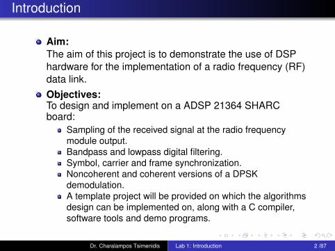
Aim:The aim of this project is to demonstrate the use of DSPhardware for the implementation of a radio frequency (RF)data link.Objectives:To design and implement on a ADSP 21364 SHARCboard:
Sampling of the received signal at the radio frequencymodule output.Bandpass and lowpass digital filtering.Symbol, carrier and frame synchronization.Noncoherent and coherent versions of a DPSKdemodulation.A template project will be provided on which the algorithmsdesign can be implemented on, along with a C compiler,software tools and demo programs.
Dr. Charalampos Tsimenidis Lab 1: Introduction 2 /87
Coursework Assessment: Demonstration (15%)
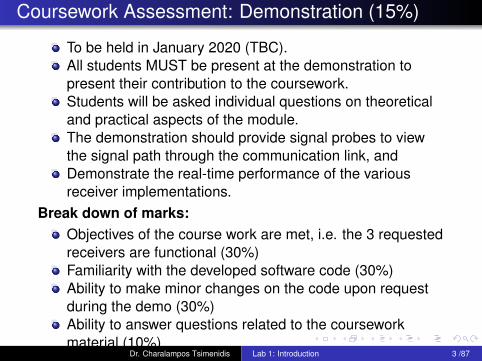
To be held in January 2020 (TBC).All students MUST be present at the demonstration topresent their contribution to the coursework.Students will be asked individual questions on theoreticaland practical aspects of the module.The demonstration should provide signal probes to viewthe signal path through the communication link, andDemonstrate the real-time performance of the variousreceiver implementations.
Break down of marks:Objectives of the course work are met, i.e. the 3 requestedreceivers are functional (30%)Familiarity with the developed software code (30%)Ability to make minor changes on the code upon requestduring the demo (30%)Ability to answer questions related to the courseworkmaterial (10%)
Dr. Charalampos Tsimenidis Lab 1: Introduction 3 /87

Coursework Assessment: Report (35%)
One formal assignment report per group is required, whichmust be submitted to General Office and electronically onthe last teaching day (Friday) of Semester 1.The report should be no less than 4500 words (excludingappendices) but longer reports are welcome.
Break down of marks:
Abstract (5%)Short background theory section (10%).Detailed description of your real time algorithmimplementation (30%).Performance results including: measurement diagrams,BER, Frame error rate and SNR computation, etc. (30%).Discussion and conclusion sections (10%).List of references (10%).Program listing appendix (5%).
Dr. Charalampos Tsimenidis Lab 1: Introduction 4 /87

Time Plan and Module Support
Lab and Lectures: 4hrs per WeekSelf-directed study whenever cluster available.Textbooks available in Library.Module support on BlackboardPersonal NCL webpage:http://www.staff.ncl.ac.uk/
charalampos.tsimenidis/EEE8091/EEE8091.html
Surgery hour: TBC
Dr. Charalampos Tsimenidis Lab 1: Introduction 5 /87
References
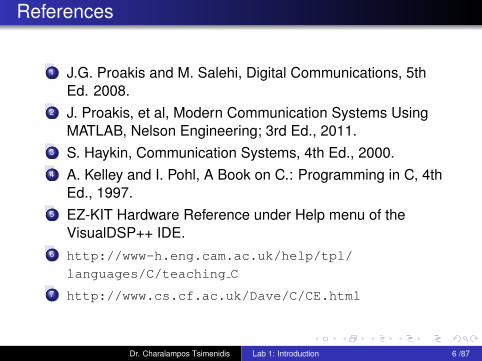
1 J.G. Proakis and M. Salehi, Digital Communications, 5thEd. 2008.
2 J. Proakis, et al, Modern Communication Systems UsingMATLAB, Nelson Engineering; 3rd Ed., 2011.
3 S. Haykin, Communication Systems, 4th Ed., 2000.4 A. Kelley and I. Pohl, A Book on C.: Programming in C, 4th
Ed., 1997.5 EZ-KIT Hardware Reference under Help menu of the
VisualDSP++ IDE.6 http://www-h.eng.cam.ac.uk/help/tpl/
languages/C/teaching C
7 http://www.cs.cf.ac.uk/Dave/C/CE.html
Dr. Charalampos Tsimenidis Lab 1: Introduction 6 /87
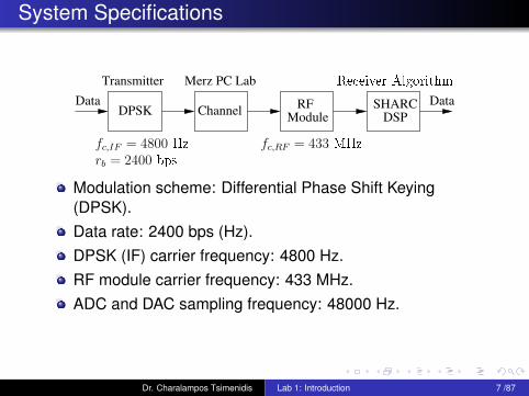
System Specifications
RF
Module DSP
DataData SHARC
Transmitter
Channel
Merz PC Lab
DPSK
rb = 2400 bps
Re eiver Algorithm
fc,IF = 4800 Hz fc,RF = 433 MHz
Modulation scheme: Differential Phase Shift Keying(DPSK).Data rate: 2400 bps (Hz).DPSK (IF) carrier frequency: 4800 Hz.RF module carrier frequency: 433 MHz.ADC and DAC sampling frequency: 48000 Hz.
Dr. Charalampos Tsimenidis Lab 1: Introduction 7 /87
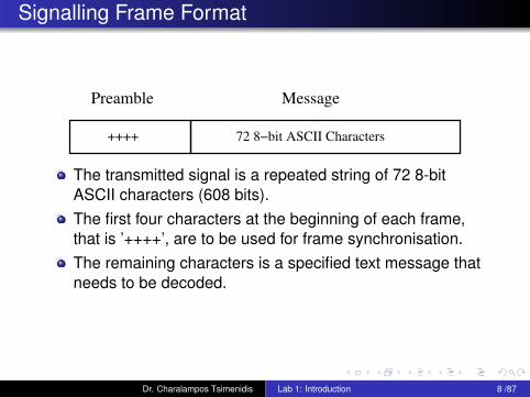
Signalling Frame Format
++++
MessagePreamble
72 8−bit ASCII Characters
The transmitted signal is a repeated string of 72 8-bitASCII characters (608 bits).The first four characters at the beginning of each frame,that is ’++++’, are to be used for frame synchronisation.The remaining characters is a specified text message thatneeds to be decoded.
Dr. Charalampos Tsimenidis Lab 1: Introduction 8 /87
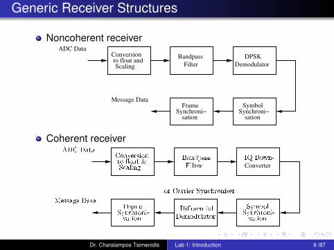
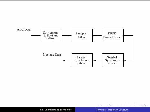
Generic Receiver Structures
Noncoherent receiverADC Data
Scaling
Conversion Bandpass
Filter
DPSK
Demodulator
SymbolSynchroni−
sation
FrameSynchroni−
sation
Message Data
to float and
Coherent receiver
Converter
Syn hroni-
Frame
sation
Symbol
ADC Data
Syn hroni-
sation
Conversion
S aling
to �oat &IQ Down-
Filter
Bandpass
Di�erential
Demodulator
Message Data
or Carrier Syn hroniser
Dr. Charalampos Tsimenidis Lab 1: Introduction 9 /87
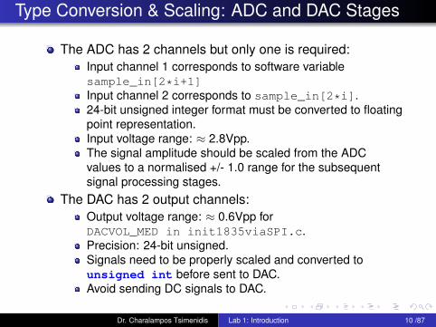
Type Conversion & Scaling: ADC and DAC Stages
The ADC has 2 channels but only one is required:Input channel 1 corresponds to software variablesample_in[2*i+1]Input channel 2 corresponds to sample_in[2*i].24-bit unsigned integer format must be converted to floatingpoint representation.Input voltage range: ≈ 2.8Vpp.The signal amplitude should be scaled from the ADCvalues to a normalised +/- 1.0 range for the subsequentsignal processing stages.
The DAC has 2 output channels:Output voltage range: ≈ 0.6Vpp forDACVOL_MED in init1835viaSPI.c.Precision: 24-bit unsigned.Signals need to be properly scaled and converted tounsigned int before sent to DAC.Avoid sending DC signals to DAC.
Dr. Charalampos Tsimenidis Lab 1: Introduction 10 /87
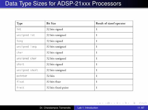
Data Type Sizes for ADSP-21xxx Processors
Dr. Charalampos Tsimenidis Lab 1: Introduction 11 /87
Variables and Constants
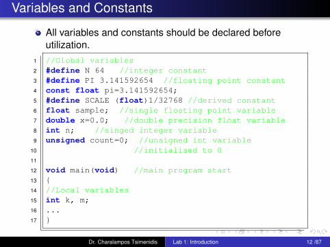
All variables and constants should be declared beforeutilization.
1 //Global variables2 #define N 64 //integer constant3 #define PI 3.141592654 //floating point constant4 const float pi=3.141592654;5 #define SCALE (float)1/32768 //derived constant6 float sample; //single floating point variable7 double x=0.0; //double precision float variable8 int n; //singed integer variable9 unsigned count=0; //unsigned int variable
10 //initialised to 011
12 void main(void) //main program start13 {14 //Local variables15 int k, m;16 ...17 }
Dr. Charalampos Tsimenidis Lab 1: Introduction 12 /87
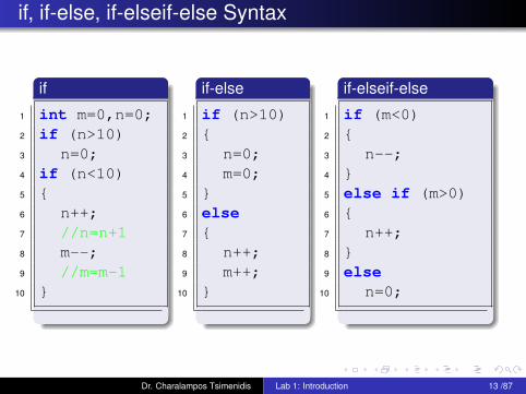
if, if-else, if-elseif-else Syntax
if
1 int m=0,n=0;2 if (n>10)3 n=0;4 if (n<10)5 {6 n++;7 //n=n+18 m--;9 //m=m-1
10 }
if-else
1 if (n>10)2 {3 n=0;4 m=0;5 }6 else7 {8 n++;9 m++;
10 }
if-elseif-else
1 if (m<0)2 {3 n--;4 }5 else if (m>0)6 {7 n++;8 }9 else
10 n=0;
Dr. Charalampos Tsimenidis Lab 1: Introduction 13 /87
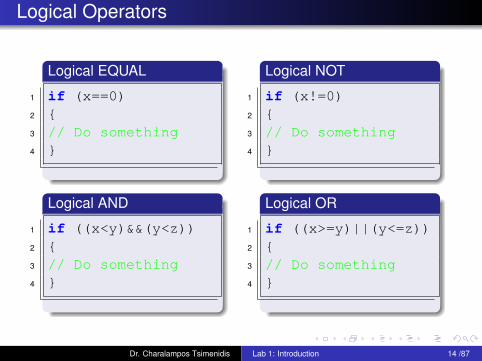
Logical Operators
Logical EQUAL
1 if (x==0)2 {3 // Do something4 }
Logical NOT
1 if (x!=0)2 {3 // Do something4 }
Logical AND
1 if ((x<y)&&(y<z))2 {3 // Do something4 }
Logical OR
1 if ((x>=y)||(y<=z))2 {3 // Do something4 }
Dr. Charalampos Tsimenidis Lab 1: Introduction 14 /87
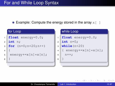
For and While Loop Syntax
Example: Compute the energy stored in the array x[ ]
for Loop
1 float energy=0.0;2 int n;3 for (n=0;n<20;n++)4 {5 energy+=x[n]*x[n];6 }
while Loop
1 float energy=0.0;2 int n=0;3 while(n<20)4 { energy+=x[n]*x[n];5 n++;6 }
Dr. Charalampos Tsimenidis Lab 1: Introduction 15 /87

Lab 1: Tasks For Today
Download and expand the sample projectMSc Coursework.zip from the modules web site.Familiarise yourself with the Visual DSP IDE, i.e. compilingthe project, download code to the board, start/stopexecution, viewing of internal variables.Familiarise yourself with the functionality of Pico Scope, i.e.displaying the RF module output, DSP board output,changing X and Y ranges, generating plots for reports.You may use the signal generator as an input signal butcheck with Pico scope carefully that the input levels areless than 2V peak-to-peak before connecting to the DSPboard.
Dr. Charalampos Tsimenidis Lab 1: Introduction 16 /87
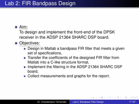
Lab 2: FIR Bandpass Design
Aim:To design and implement the front-end of the DPSKreceiver in the ADSP 21364 SHARC DSP board.Objectives:
Design in Matlab a bandpass FIR filter that meets a givenset of specifications,Transfer the coefficients of the designed FIR filter fromMatlab into a C-like structure format,Implement the filtering in the ADSP 21364 SHARC DSPboard,Collect measurements and graphs for the report.
Dr. Charalampos Tsimenidis Lab 2: Bandpass Filter Design 17 /87
ADC Data
Scaling
Conversion Bandpass
Filter
DPSK
Demodulator
SymbolSynchroni−
sation
FrameSynchroni−
sation
Message Data
to float and
Dr. Charalampos Tsimenidis Reminder: Receiver Structure

Why do we need a bandpass filter ?
Receiver Front−End
Bandpass
Filterx1x0
sample_in[2*i]
IF InputConversion
Scalingto �oat and
FIR Matched Filter
20−Tap Delay Line
DPSK Demodulator
1
x2[0]
x1
x2[19]
1920
x3
x2[19]
state_mf[ ]
x1 x4
h_mf[ ]
Dr. Charalampos Tsimenidis Lab 2: Bandpass Filter Design 18 /87

Effect of Down-conversion
sin(A)︸ ︷︷ ︸x1
sin(B)︸ ︷︷ ︸x2[19]
=1
2sin(A−B) +
1
2sin(A+B)
whereA = ωct+ φ(t)
andB = ωct+ θ(t)
Thus, we obtain a term on baseband:
A−B = φ(t)− θ(t)
and a double-frequency term:
A+B = 2ωct+ φ(t) + θ(t)
Dr. Charalampos Tsimenidis Lab 2: Bandpass Filter Design 19 /87
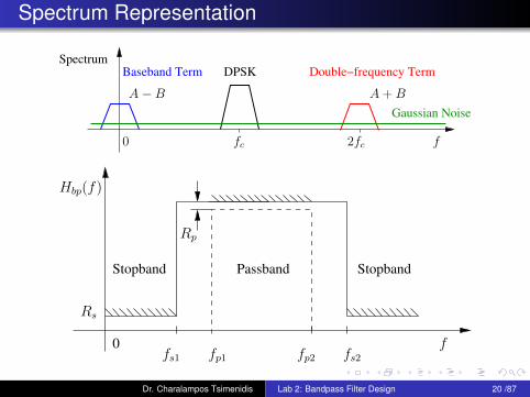
Spectrum Representation
Gaussian Noise
Double−frequency TermBaseband Term DPSKSpectrum
2fc0 fc
A−B A+B
f
PassbandStopband Stopband
0
Rs
fs2fp2fp1fs1
Rp
Hbp(f)
f
Dr. Charalampos Tsimenidis Lab 2: Bandpass Filter Design 20 /87
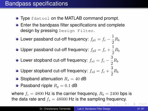
Bandpass specifications
Type fdatool on the MATLAB command prompt.Enter the bandpass filter specifications and completedesign by pressing Design Filter.
Lower passband cut-off frequency: fp1 = fc −1
2Rb
Upper passband cut-off frequency: fp2 = fc +1
2Rb
Lower stopband cut-off frequency: fs1 = fc −3
2Rb
Upper stopband cut-off frequency: fs2 = fc +3
2Rb
Stopband attenuation Rs = 40 dBPassband ripple Rp = 0.1 dB
where fc = 4800 Hz is the carrier frequency, Rb = 2400 bps isthe data rate and fs = 48000 Hz is the sampling frequency.
Dr. Charalampos Tsimenidis Lab 2: Bandpass Filter Design 21 /87
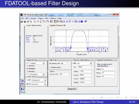
FDATOOL-based Filter Design
Dr. Charalampos Tsimenidis Lab 2: Bandpass Filter Design 22 /87
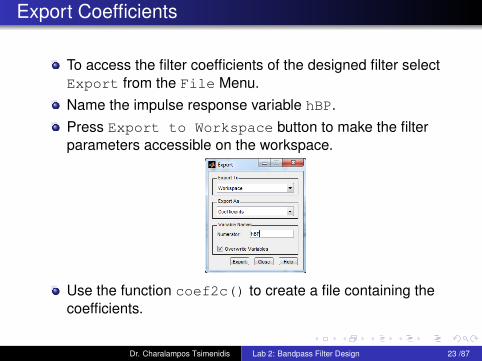
Export Coefficients
To access the filter coefficients of the designed filter selectExport from the File Menu.Name the impulse response variable hBP.Press Export to Workspace button to make the filterparameters accessible on the workspace.
Use the function coef2c() to create a file containing thecoefficients.
Dr. Charalampos Tsimenidis Lab 2: Bandpass Filter Design 23 /87

FIR Implementation of the Bandpass Filter
The header file #include <filters.h> should beincluded in the main file.This include file contains the function fir(), which can beused to perform the filtering.Check the help to obtain support for this function.The general syntax is
1 output=fir(input,coeffs,state,no_of_taps);
Use #define to declare the size of the bandpass filter.
z−1
bMb0
x[n− 1] x[n−M ]z−1
b1 bM−1
x[n−M − 1]x[n]
y[n]
Dr. Charalampos Tsimenidis Lab 2: Bandpass Filter Design 24 /87
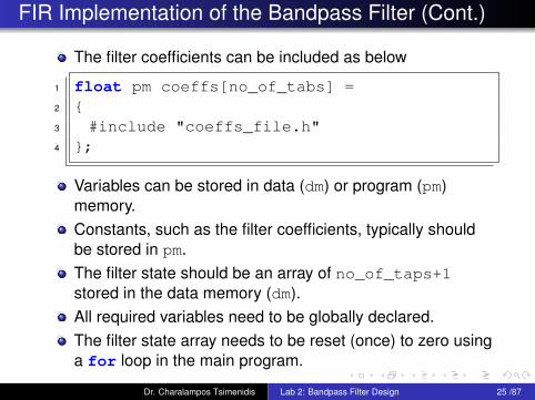
FIR Implementation of the Bandpass Filter (Cont.)
The filter coefficients can be included as below
1 float pm coeffs[no_of_tabs] =2 {3 #include "coeffs_file.h"4 };
Variables can be stored in data (dm) or program (pm)memory.Constants, such as the filter coefficients, typically shouldbe stored in pm.The filter state should be an array of no_of_taps+1stored in the data memory (dm).All required variables need to be globally declared.The filter state array needs to be reset (once) to zero usinga for loop in the main program.
Dr. Charalampos Tsimenidis Lab 2: Bandpass Filter Design 25 /87

Signal Generator and Picoscope Settings
Signal Generator
Sinusoidal signal: 100 - 200 mVppSweep:
Linear sweep,Start frequency: 10 Hz,Stop frequency: 14 kHz,Sweep time: 10 ms.
PicoscopeSpectrum Mode, both A and B channels on,Sampling frequency: 39.06 kHz,Spectrum Options:
Display Mode: Peak Hold,Remaining parameters at default setting.Set optimal FFT length and window type.
Dr. Charalampos Tsimenidis Lab 2: Bandpass Filter Design 26 /87

Bandpass Functionality Check
Dr. Charalampos Tsimenidis Lab 2: Bandpass Filter Design 27 /87
Lab 3: Aim and Objectives
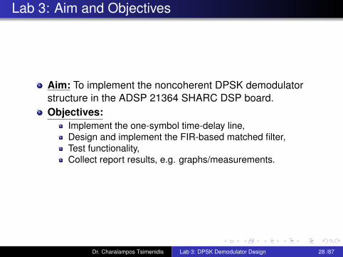
Aim: To implement the noncoherent DPSK demodulatorstructure in the ADSP 21364 SHARC DSP board.Objectives:
Implement the one-symbol time-delay line,Design and implement the FIR-based matched filter,Test functionality,Collect report results, e.g. graphs/measurements.
Dr. Charalampos Tsimenidis Lab 3: DPSK Demodulator Design 28 /87
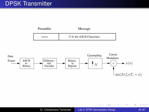
DPSK Transmitter
++++
MessagePreamble
72 8−bit ASCII Characters
Data
Frame
Binary
ASCII Binary
Bipolartoto
Modulator
CarrierUpsampling
Encoder
Differen−tial N
sin(2πfcnTs + φ)
x(n)
Dr. Charalampos Tsimenidis Lab 3: DPSK Demodulator Design 29 /87
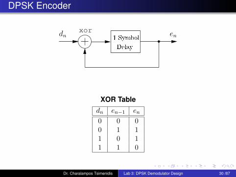
DPSK Encoder
xor
Delay
1 Symbol
dn en
XOR Tabledn en−1 en
0 0 00 1 11 0 11 1 0
Dr. Charalampos Tsimenidis Lab 3: DPSK Demodulator Design 30 /87

Principle of Noncoherent DPSK Demodulator
xor
Delay
1 Symbol
en dn
Dr. Charalampos Tsimenidis Lab 3: DPSK Demodulator Design 31 /87
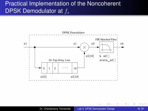
Practical Implementation of the NoncoherentDPSK Demodulator at fs
FIR Matched Filter
20−Tap Delay Line
DPSK Demodulator
1
x2[0]
x1
x2[19]
1920
x3
x2[19]
state_mf[ ]
x1 x4
h_mf[ ]
Dr. Charalampos Tsimenidis Lab 3: DPSK Demodulator Design 32 /87
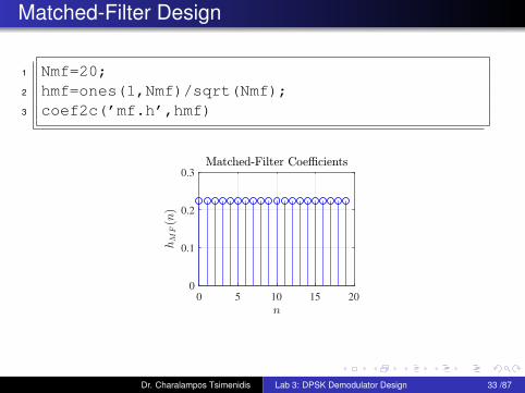
Matched-Filter Design
1 Nmf=20;2 hmf=ones(1,Nmf)/sqrt(Nmf);3 coef2c(’mf.h’,hmf)
0
0.1
0.2
0.3
0 5 10 15 20
Dr. Charalampos Tsimenidis Lab 3: DPSK Demodulator Design 33 /87
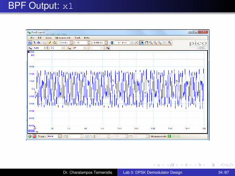
BPF Output: x1
Dr. Charalampos Tsimenidis Lab 3: DPSK Demodulator Design 34 /87
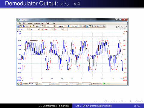
Demodulator Output: x3, x4
Dr. Charalampos Tsimenidis Lab 3: DPSK Demodulator Design 35 /87
Lab 3 Tasks
The following tasks need to be completed:Define required variables,Initialize delay-line vector to zero,Implement delay-line update mechanism,Implement demodulator,Design and implement matched filter,Collect measurements and graphs for the report.
Dr. Charalampos Tsimenidis Lab 3: DPSK Demodulator Design 36 /87
Lab 4: Aim & Objectives
Aim:To implement the early-late symbol synchronizationstructure for DPSK.
Objectives:Buffering of the demodulator output.Early-late energy computation.Control of the buffer update.Symbol decision variable.
Dr. Charalampos Tsimenidis Lab 4: Early-Late Symbol Synchronization 37 /87
Symbol Timing Estimation
Phase can be ignored for differential types of modulation.Sample demodulator output periodically at tn = nT + τ
T is the symbol interval and τ is the timing mismatch dueto the propagation delay. We therefore, need tosynchronize the receiver clock, i.e recover symbol timing.Different timing methods exist:
Feedforward or one-shot estimators.Feedback or tracking estimators.
Dr. Charalampos Tsimenidis Lab 4: Early-Late Symbol Synchronization 38 /87
ML Timing Synchronisation
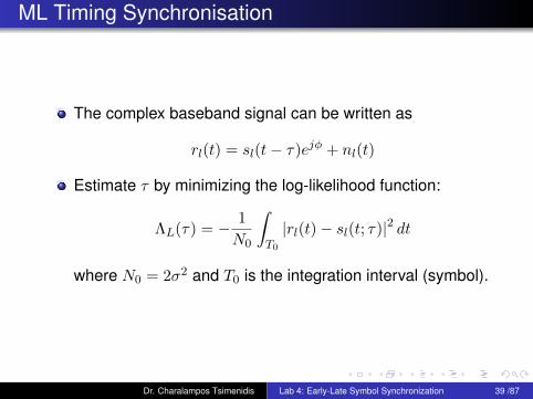
The complex baseband signal can be written as
rl(t) = sl(t− τ)ejφ + nl(t)
Estimate τ by minimizing the log-likelihood function:
ΛL(τ) = − 1
N0
∫T0
|rl(t)− sl(t; τ)|2 dt
where N0 = 2σ2 and T0 is the integration interval (symbol).
Dr. Charalampos Tsimenidis Lab 4: Early-Late Symbol Synchronization 39 /87
Early-Late Approximation
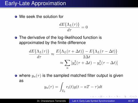
We seek the solution for
dE{ΛL(τ)}dτ
= 0
The derivative of the log-likelihood function isapproximated by the finite difference
dE{ΛL(τ)}dτ
≈ E{ΛL(τ + ∆t)} − E{ΛL(τ −∆t)}2∆t
≈∑n
[y2n(τ + ∆t)− y2n(τ −∆t)]
where yn(τ) is the sampled matched filter output is givenas
yn(τ) =
∫T0
rl(t)g(t− nT − τ)dt
Dr. Charalampos Tsimenidis Lab 4: Early-Late Symbol Synchronization 40 /87
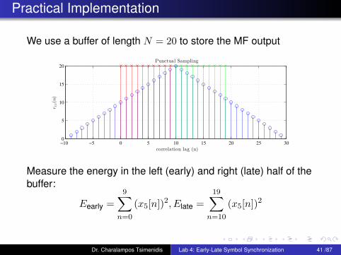
Practical Implementation
We use a buffer of length N = 20 to store the MF output
−10 −5 0 5 10 15 20 25 300
5
10
15
20
correlation lag (n)
rxx(n)
Punctual Sampling
Measure the energy in the left (early) and right (late) half of thebuffer:
Eearly =
9∑n=0
(x5[n])2, Elate =
19∑n=10
(x5[n])2
Dr. Charalampos Tsimenidis Lab 4: Early-Late Symbol Synchronization 41 /87
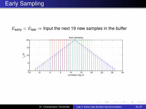
Early Sampling
Eearly < Elate ⇒ Input the next 19 new samples in the buffer
−10 −5 0 5 10 15 20 25 30 350
5
10
15
20
correlation lag (n)
r xx(n
)
Early Sampling
Dr. Charalampos Tsimenidis Lab 4: Early-Late Symbol Synchronization 42 /87

Late Sampling
Eearly > Elate ⇒ Input the next 21 new samples in the buffer
−15 −10 −5 0 5 10 15 20 25 300
5
10
15
20
correlation lag (n)
r xx(n
)
Late Sampling
Dr. Charalampos Tsimenidis Lab 4: Early-Late Symbol Synchronization 43 /87

Lab 4 Tasks: Buffer Variables, Initialization and Update
How to implement the Early-Late Gate method in C ?
The following tasks need to be completed:A floating-point type array of 20 samples x5[20] shouldbe used to buffer the matched filter output.
Define the buffer x5 (as we did in Lab 4).Initialise the buffer contents to zeros (inside the main).
A unsigned int variable Nc1 is required to control theamount of samples that are shifted inside the buffer.
Define a counter variable Nc1 and initialise it to 20.Implement using Nc1 the code that shifts Nc1 samplesinside the buffer.The set of values that this variable can take is {19, 20, 21}.
Dr. Charalampos Tsimenidis Lab 4: Early-Late Symbol Synchronization 44 /87

Lab 4 Tasks: Energy Computation
The following tasks need to be completed:After Nc1 samples are inside the buffer, the energies of theearly and late parts are to be computed as:
Eearly =
9∑n=0
(x5[n])2, Elate =
19∑n=10
(x5[n])2
Define two floating point variables Ee and El.Using a for loop, compute the energies of the early andlate parts iteratively, e.g.Ee=Ee+x5[n]*x5[n];El=El+x5[n+10]*x5[n+10];
The computation of Ee and El should always start withEe=0 and El=0.
Dr. Charalampos Tsimenidis Lab 4: Early-Late Symbol Synchronization 45 /87
Lab 4 Tasks: Buffer Update Control
The following tasks need to be completed:Ee and El should be compared on symbol-by-symbolbasis and a signed int counter variable Nc2 should beused to keep track of the changes.Define Nc2 as signed int and initialise it to zero.Implement in code the logic to adjust Nc1 and Nc2.
Specifically, if Ee>El then 1 is added to Nc2. Otherwise, ifEe<El then -1 is added to Nc2.The variable Nc2 is used then to adjust Nc1 that controlsthe amount of samples shifted inside the buffer x5.E.g., if Nc2>=10 then Nc1=21, else if Nc2<=-10 thenNc1=19, otherwise Nc1=20.When one of the thresholds of Nc2 (10 or -10) is reachedNc2 should be reset to zero.
The symbol decision is taken based on the value of thevariable Em=0.5*(x5[9]+x5[10]);
Define and implement the code for Em.
Dr. Charalampos Tsimenidis Lab 4: Early-Late Symbol Synchronization 46 /87
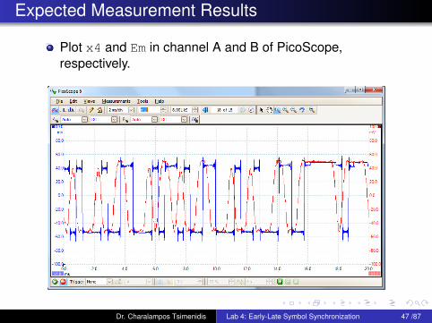
Expected Measurement Results
Plot x4 and Em in channel A and B of PicoScope,respectively.
Dr. Charalampos Tsimenidis Lab 4: Early-Late Symbol Synchronization 47 /87
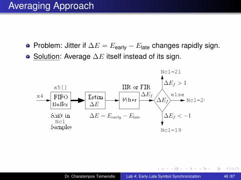
Averaging Approach
Problem: Jitter if ∆E = Eearly − Elate changes rapidly sign.Solution: Average ∆E itself instead of its sign.
Nc1=21
Nc1=20
elsex4
x5[]
Nc1
Nc1=19
Filter
∆Ef < −1
∆Ef > 1
∆Ef
∆EfFIFO
Bu�er
Shift in
Samples
Estim.
∆E
IIR or FIR
∆E = Eearly −Elate
Dr. Charalampos Tsimenidis Lab 4: Early-Late Symbol Synchronization 48 /87
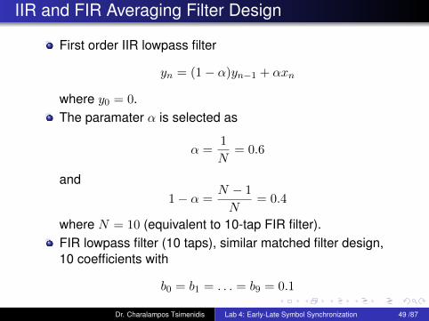
IIR and FIR Averaging Filter Design
First order IIR lowpass filter
yn = (1− α)yn−1 + αxn
where y0 = 0.The paramater α is selected as
α =1
N= 0.6
and1− α =
N − 1
N= 0.4
where N = 10 (equivalent to 10-tap FIR filter).FIR lowpass filter (10 taps), similar matched filter design,10 coefficients with
b0 = b1 = . . . = b9 = 0.1
Dr. Charalampos Tsimenidis Lab 4: Early-Late Symbol Synchronization 49 /87
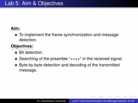
Lab 5: Aim & Objectives
Aim:To implement the frame synchronization and messagedetection.
Objectives:Bit detection.Searching of the preamble “++++” in the received signal.Byte-by-byte detection and decoding of the transmittedmessage.
Dr. Charalampos Tsimenidis Lab 5: Frame Synchronization and Message Detection 50 /87
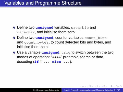
Variables and Programme Structure
Define two unsigned variables, preamble anddatachar, and initialise them zero.Define two unsigned, counter variables count_bitsand count_bytes, to count detected bits and bytes, andinitialise them zero.Use a variable unsigned trig to switch between the twomodes of operation: “++++” preamble search or datadecoding (if()... else ...).
Dr. Charalampos Tsimenidis Lab 5: Frame Synchronization and Message Detection 51 /87
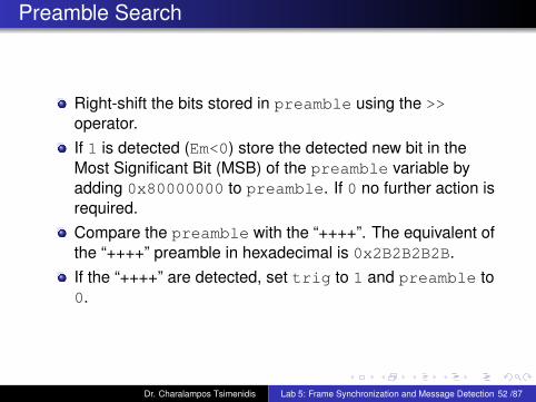
Preamble Search
Right-shift the bits stored in preamble using the >>operator.If 1 is detected (Em<0) store the detected new bit in theMost Significant Bit (MSB) of the preamble variable byadding 0x80000000 to preamble. If 0 no further action isrequired.Compare the preamble with the “++++”. The equivalent ofthe “++++” preamble in hexadecimal is 0x2B2B2B2B.If the “++++” are detected, set trig to 1 and preamble to0.
Dr. Charalampos Tsimenidis Lab 5: Frame Synchronization and Message Detection 52 /87
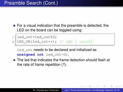
Preamble Search (Cont.)
For a visual indication that the preamble is detected, theLED on the board can be toggled using:
1 led_cnt=led_cnt%2;2 LED_ON(led_cnt++); // LED 1 on|off
led_cnt needs to be declared and initialized asunsigned int led_cnt=0;.The led that indicates the frame detection should flash atthe rate of frame repetition (?).
Dr. Charalampos Tsimenidis Lab 5: Frame Synchronization and Message Detection 53 /87
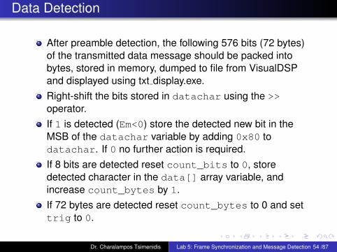
Data Detection
After preamble detection, the following 576 bits (72 bytes)of the transmitted data message should be packed intobytes, stored in memory, dumped to file from VisualDSPand displayed using txt display.exe.Right-shift the bits stored in datachar using the >>operator.If 1 is detected (Em<0) store the detected new bit in theMSB of the datachar variable by adding 0x80 todatachar. If 0 no further action is required.If 8 bits are detected reset count_bits to 0, storedetected character in the data[] array variable, andincrease count_bytes by 1.If 72 bytes are detected reset count_bytes to 0 and settrig to 0.
Dr. Charalampos Tsimenidis Lab 5: Frame Synchronization and Message Detection 54 /87
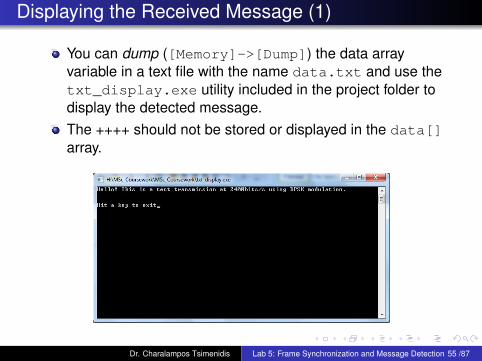
Displaying the Received Message (1)
You can dump ([Memory]->[Dump]) the data arrayvariable in a text file with the name data.txt and use thetxt_display.exe utility included in the project folder todisplay the detected message.The ++++ should not be stored or displayed in the data[]array.
Dr. Charalampos Tsimenidis Lab 5: Frame Synchronization and Message Detection 55 /87
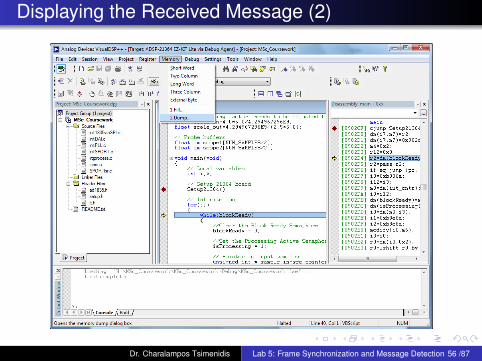
Displaying the Received Message (2)
Dr. Charalampos Tsimenidis Lab 5: Frame Synchronization and Message Detection 56 /87
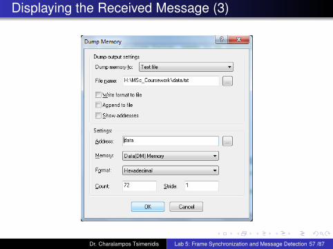
Displaying the Received Message (3)
Dr. Charalampos Tsimenidis Lab 5: Frame Synchronization and Message Detection 57 /87
Lab 6: Aim & Objectives
Aim:To implement the DPSK signal down-conversion tocomplex baseband and early-late gate based symbolsynchronization.
Objectives:Generate and store look-up tables for cosine and sineoscillators in Matlab.Include look-up tables in the C program.Implement index control for the look-up table in C.Implement early-late gate synchronization in C using I-Qenergy computation.Obtain graphical results at the various stage outputs.
Dr. Charalampos Tsimenidis Lab 6: Down-conversion and Symbol Synchronization 58 /87
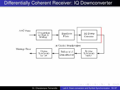
Differentially Coherent Receiver: IQ Downconverter
Converter
Syn hroni-
Frame
sation
Symbol
ADC Data
Syn hroni-
Conversion
S aling
to �oat &IQ Down-
Filter
Bandpass
Di�erential
Demodulator
Message Data
or Carrier Syn hroniser
zation
Dr. Charalampos Tsimenidis Lab 6: Down-conversion and Symbol Synchronization 59 /87
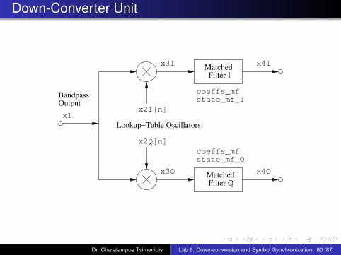
Down-Converter Unit
Matched
Matched
x1
state_mf_Q
Filter Q
Filter I
BandpassOutput
Lookup−Table Oscillators
coeffs_mf
coeffs_mf
state_mf_I
x3I
x3Q
x4I
x4Q
x2Q[n]
x2I[n]
Dr. Charalampos Tsimenidis Lab 6: Down-conversion and Symbol Synchronization 60 /87
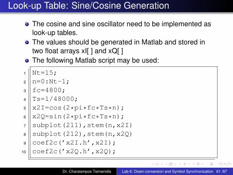
Look-up Table: Sine/Cosine Generation
The cosine and sine oscillator need to be implemented aslook-up tables.The values should be generated in Matlab and stored intwo float arrays xI[ ] and xQ[ ]The following Matlab script may be used:
1 Nt=15;2 n=0:Nt-1;3 fc=4800;4 Ts=1/48000;5 x2I=cos(2*pi*fc*Ts*n);6 x2Q=sin(2*pi*fc*Ts*n);7 subplot(211),stem(n,x2I)8 subplot(212),stem(n,x2Q)9 coef2c(’x2I.h’,x2I);
10 coef2c(’x2Q.h’,x2Q);
Dr. Charalampos Tsimenidis Lab 6: Down-conversion and Symbol Synchronization 61 /87
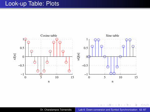
Look-up Table: Plots
0 5 10 15−1
−0.5
0
0.5
1
Cosine table
xI[
n]
n
0 5 10 15−1
−0.5
0
0.5
1
Sine table
xQ
[n]
n
Dr. Charalampos Tsimenidis Lab 6: Down-conversion and Symbol Synchronization 62 /87
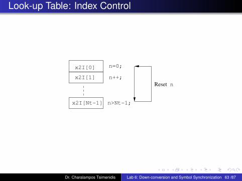
Look-up Table: Index Control
nReset
x2I[0]
x2I[1]
x2I[Nt−1] n>Nt−1;
n=0;
n++;
Dr. Charalampos Tsimenidis Lab 6: Down-conversion and Symbol Synchronization 63 /87
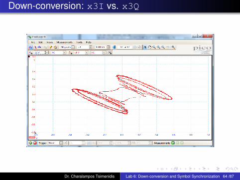
Down-conversion: x3I vs. x3Q
Dr. Charalampos Tsimenidis Lab 6: Down-conversion and Symbol Synchronization 64 /87
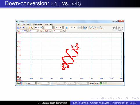
Down-conversion: x4I vs. x4Q
Dr. Charalampos Tsimenidis Lab 6: Down-conversion and Symbol Synchronization 65 /87
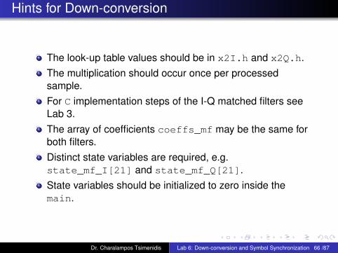
Hints for Down-conversion
The look-up table values should be in x2I.h and x2Q.h.The multiplication should occur once per processedsample.For C implementation steps of the I-Q matched filters seeLab 3.The array of coefficients coeffs_mf may be the same forboth filters.Distinct state variables are required, e.g.state_mf_I[21] and state_mf_Q[21].State variables should be initialized to zero inside themain.
Dr. Charalampos Tsimenidis Lab 6: Down-conversion and Symbol Synchronization 66 /87
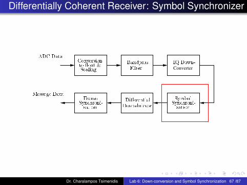
Differentially Coherent Receiver: Symbol Synchronizer
Converter
Syn hroni-
Frame
sation
Symbol
ADC Data
Syn hroni-
Conversion
S aling
to �oat &IQ Down-
Filter
Bandpass
Di�erential
Demodulator
Message Data
zation
Dr. Charalampos Tsimenidis Lab 6: Down-conversion and Symbol Synchronization 67 /87
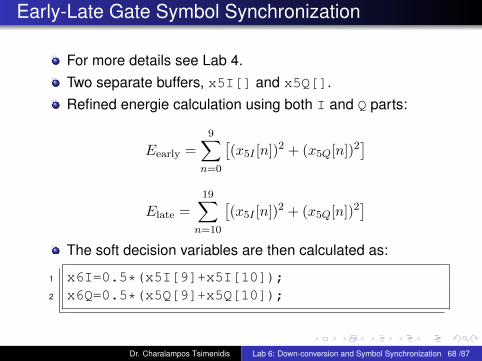
Early-Late Gate Symbol Synchronization
For more details see Lab 4.Two separate buffers, x5I[] and x5Q[].Refined energie calculation using both I and Q parts:
Eearly =
9∑n=0
[(x5I [n])2 + (x5Q[n])2
]
Elate =
19∑n=10
[(x5I [n])2 + (x5Q[n])2
]The soft decision variables are then calculated as:
1 x6I=0.5*(x5I[9]+x5I[10]);2 x6Q=0.5*(x5Q[9]+x5Q[10]);
Dr. Charalampos Tsimenidis Lab 6: Down-conversion and Symbol Synchronization 68 /87
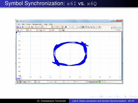
Symbol Synchronization: x6I vs. x6Q
Dr. Charalampos Tsimenidis Lab 6: Down-conversion and Symbol Synchronization 69 /87

Lab 7-8: Aim & Objectives
Aim:To implement the DPSK differentially coherent detector.
Objectives:Declare and initialize appropriately the required variables.Implement the equation for differentially coherent detector.Monitor and record in PicoScope the IQ constellationbefore and after the detector.Implement the preamble and message detection.
Dr. Charalampos Tsimenidis Lab 7-8: Differentially Coherent Decoding 70 /87
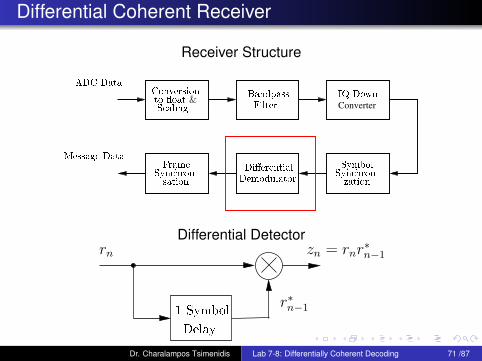
Differential Coherent Receiver
Receiver Structure
Converter
Syn hroni-
Frame
sation
Symbol
ADC Data
Syn hroni-
Conversion
S aling
to �oat &IQ Down-
Filter
Bandpass
Di�erential
Demodulator
Message Data
zation
Differential Detector
Delay
1 Symbol
rn
r∗n−1
zn = rnr∗n−1
Dr. Charalampos Tsimenidis Lab 7-8: Differentially Coherent Decoding 71 /87
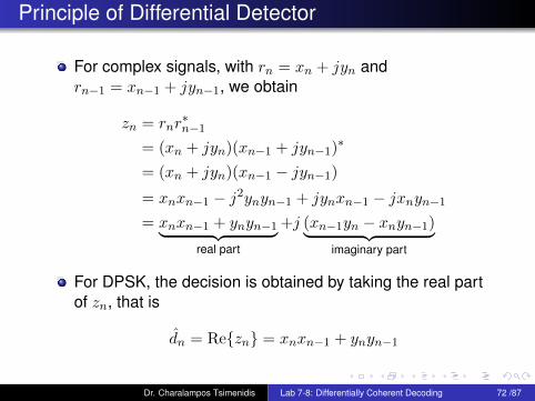
Principle of Differential Detector
For complex signals, with rn = xn + jyn andrn−1 = xn−1 + jyn−1, we obtain
zn = rnr∗n−1
= (xn + jyn)(xn−1 + jyn−1)∗
= (xn + jyn)(xn−1 − jyn−1)
= xnxn−1 − j2ynyn−1 + jynxn−1 − jxnyn−1
= xnxn−1 + ynyn−1︸ ︷︷ ︸real part
+j (xn−1yn − xnyn−1)︸ ︷︷ ︸imaginary part
For DPSK, the decision is obtained by taking the real partof zn, that is
dn = Re{zn} = xnxn−1 + ynyn−1
Dr. Charalampos Tsimenidis Lab 7-8: Differentially Coherent Decoding 72 /87

Practical Implementation
xn → x6I
yn → x6Q
xn−1 → x6I_prev
yn−1 → x6Q_prev
x6I_prev and x6Q_prev denote the values of x6I andx6I from the previous symbol.x6I_prev and x6Q_prev should be initialized to zero atdeclaration.Hard decision is then achieved by deciding whether the dIvalue is positive or negative, with a negative valueindicating that a logic 1 was transmitted.
1 dI=x6I*x6I_prev+x6Q*x6Q_prev;2 dQ=x6I_prev*x6Q-x6I*x6Q_prev;
Dr. Charalampos Tsimenidis Lab 7-8: Differentially Coherent Decoding 73 /87
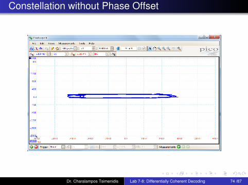
Constellation without Phase Offset
Dr. Charalampos Tsimenidis Lab 7-8: Differentially Coherent Decoding 74 /87
Frame Synchronization and Message Detection
Same as described in Lab 5.Em should be replaced by dI for the bit detection.LED flashing should be used to display preamble detection.
Dr. Charalampos Tsimenidis Lab 7-8: Differentially Coherent Decoding 75 /87
Lab 9: Aim & Objectives
Aim:To implement the Costas loop based carrier phaserecovery method.
Objectives:Declare and initialize appropriately the required variables.Implement the equations for the Costas loop based carrierphase recovery.Monitor and record in PicoScope the IQ constellationbefore and after the detector.Implement the preamble and message detection.
Dr. Charalampos Tsimenidis Lab 9: Carrier-Phase Recovery using the Costas Loop 76 /87
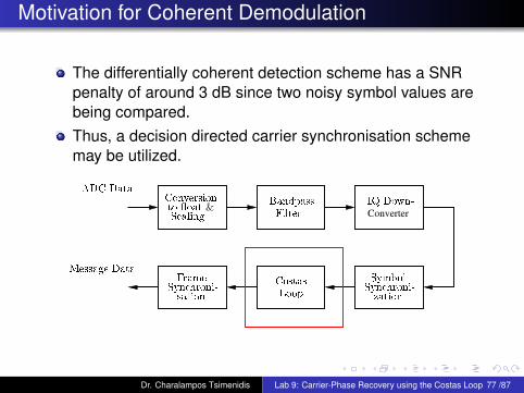
Motivation for Coherent Demodulation
The differentially coherent detection scheme has a SNRpenalty of around 3 dB since two noisy symbol values arebeing compared.Thus, a decision directed carrier synchronisation schememay be utilized.
Converter
Syn hroni-
Frame
sation
Symbol
ADC Data
Syn hroni-
Conversion
S aling
to �oat &IQ Down-
Filter
Bandpass
Message Data
Costas
Loop
zation
Dr. Charalampos Tsimenidis Lab 9: Carrier-Phase Recovery using the Costas Loop 77 /87

Theoretical BER Performance for DPSK
Pe =1
2e−Eb
N0
0 2 4 6 8 1010
−6
10−5
10−4
10−3
10−2
10−1
100
Eb/N
0 (dB)
BE
R
BPSK
DPSK
Dr. Charalampos Tsimenidis Lab 9: Carrier-Phase Recovery using the Costas Loop 78 /87
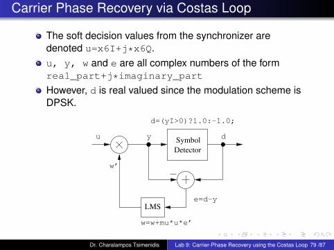
Carrier Phase Recovery via Costas Loop
The soft decision values from the synchronizer aredenoted u=x6I+j*x6Q.u, y, w and e are all complex numbers of the formreal_part+j*imaginary_part
However, d is real valued since the modulation scheme isDPSK.
u y dSymbol
Detector
LMSe=d−y
d=(yI>0)?1.0:−1.0;
w’
w=w+mu*u*e’
Dr. Charalampos Tsimenidis Lab 9: Carrier-Phase Recovery using the Costas Loop 79 /87

Costas Loop Algorithm
Initialization:1 Adjust scaling so that I-Q symbol values have a magnitude
of approximately 1.0.2 Initialize the phase correction term w=1.0 (no phase
correction).Subsequently, for each symbol received:
1 Perform complex multiplication of w and u to obtain y.2 Hardlimit yI to obtain d:if yI>0 then d=1.0 else d=-1.0.
3 Calculate the error signal using: e=d-y.4 Update the phase correction term using the least mean
square (LMS) algorithm:w=w+mu*u*e’, where e’ is the conjugate complex of e.
Dr. Charalampos Tsimenidis Lab 9: Carrier-Phase Recovery using the Costas Loop 80 /87

Notes
1 The phase recovery algorithm is described in complexnotation, however, it should be implemented using the realand imaginary parts of the variables.
2 The adaptive step size mu must be varied until satisfactoryresults are obtained but it is recommend to start with avalue of mu=0.001.
3 To obtain the transmitted bit sequence you must finallyperform differential decoding of d, i.e. if d=d_prev thenthe transmitted bit is a logic “0”, otherwise the transmittedbit is a logic “1”.
Dr. Charalampos Tsimenidis Lab 9: Carrier-Phase Recovery using the Costas Loop 81 /87
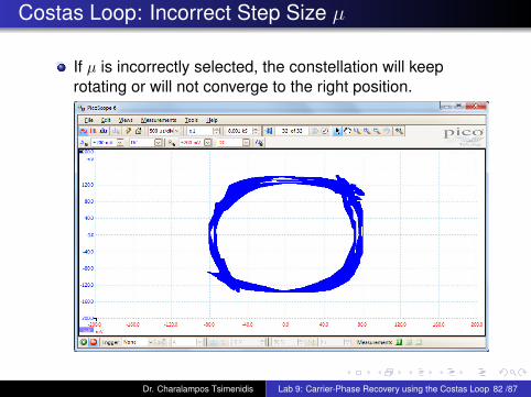
Costas Loop: Incorrect Step Size µ
If µ is incorrectly selected, the constellation will keeprotating or will not converge to the right position.
Dr. Charalampos Tsimenidis Lab 9: Carrier-Phase Recovery using the Costas Loop 82 /87
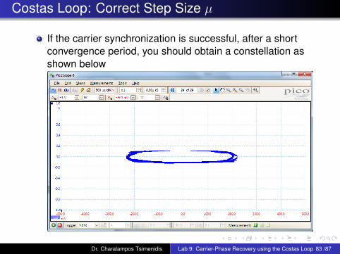
Costas Loop: Correct Step Size µ
If the carrier synchronization is successful, after a shortconvergence period, you should obtain a constellation asshown below
Dr. Charalampos Tsimenidis Lab 9: Carrier-Phase Recovery using the Costas Loop 83 /87
Frame Synchronization and Message Detection
Same as described in Lab 5.Em should be replaced by d for the bit detection.LED flashing should be used to display preamble detection.
Dr. Charalampos Tsimenidis Lab 9: Carrier-Phase Recovery using the Costas Loop 84 /87
Lab 10-12: Additional Tasks
Objectives:Implementation of Automatic Gain Control (AGC).Bit and Frame Error Rate (BER/FER) computation.Signal to noise ratio (SNR) computation aftersynchronization.Comparison between theoretical and measured BERresults.Alternative symbol synchronization schemes.
Dr. Charalampos Tsimenidis Lab 10-12: Additional Tasks 85 /87
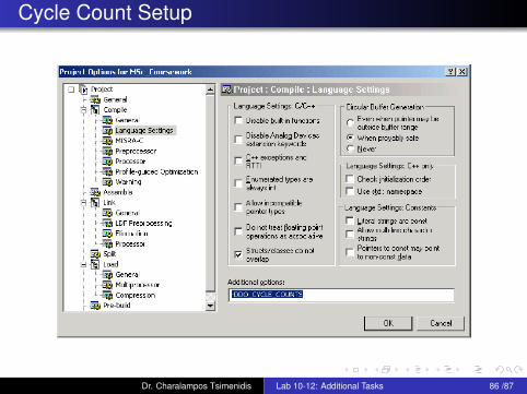
Cycle Count Setup
Dr. Charalampos Tsimenidis Lab 10-12: Additional Tasks 86 /87
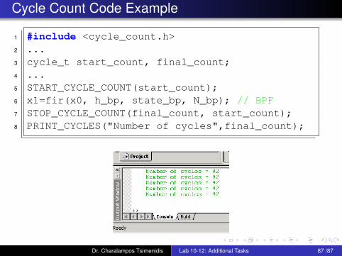
Cycle Count Code Example
1 #include <cycle_count.h>2 ...3 cycle_t start_count, final_count;4 ...5 START_CYCLE_COUNT(start_count);6 x1=fir(x0, h_bp, state_bp, N_bp); // BPF7 STOP_CYCLE_COUNT(final_count, start_count);8 PRINT_CYCLES("Number of cycles",final_count);
Dr. Charalampos Tsimenidis Lab 10-12: Additional Tasks 87 /87