ee 477 final report - engineering.purdue.edu fileece 477 final report spring 2008 -1- abstract...
TRANSCRIPT

ECE 477 Final Report Spring 2008
Team 4 Agatha
Team Members:
#1: _Zach Dicklin________________ Signature: ____________________ Date: _________
#2: _Ian Bacon__________________ Signature: ____________________ Date: _________
#3: _Amy Ritter_________________ Signature: ____________________ Date: _________
#4: _Eric Yee___________________ Signature: ____________________ Date: _________
CRITERION SCORE MPY PTS
Technical content 0 1 2 3 4 5 6 7 8 9 10 3
Design documentation 0 1 2 3 4 5 6 7 8 9 10 3
Technical writing style 0 1 2 3 4 5 6 7 8 9 10 2
Contributions 0 1 2 3 4 5 6 7 8 9 10 1
Editing 0 1 2 3 4 5 6 7 8 9 10 1
Comments: TOTAL

ECE 477 Final Report Spring 2008
-ii-
TABLE OF CONTENTS
Abstract 1
1.0 Project Overview and Block Diagram 1
2.0 Team Success Criteria and Fulfillment 2
3.0 Constraint Analysis and Component Selection 3
4.0 Patent Liability Analysis 9
5.0 Reliability and Safety Analysis 13
6.0 Ethical and Environmental Impact Analysis 18
7.0 Packaging Design Considerations 23
8.0 Schematic Design Considerations 28
9.0 PCB Layout Design Considerations 34
10.0 Software Design Considerations 38
11.0 Version 2 Changes 43
12.0 Summary and Conclusions 44
13.0 References 45
Appendix A: Individual Contributions A1
Appendix B: Packaging B1
Appendix C: Schematic C1
Appendix D: PCB Layout Top and Bottom Copper D1
Appendix E: Parts List Spreadsheet E1
Appendix F: Software Listing F1
Appendix G: FMECA Worksheet G1

ECE 477 Final Report Spring 2008
-1-
Abstract
Agatha is a targeted advertising solution for commercial shopping centers. A recent
article from IPMagazine estimates that 83% of advertising money is wasted. Only a measly 27%
of advertisements today are reaching their correct audiences [1]. Dog food commercials are seen
by people without dogs, and toys for children are shown to adults without any children.
However, using RFID-tagged shopping bags and an updatable user preference database,
Agatha‟s system can target advertisements directly to consumers. This report details the design
process that the design team of Ian Bacon, Zach Dicklin, Amy Ritter, and Eric Yee.
1.0 Project Overview and Block Diagram
Advertising is a rather new concept. Today‟s top advertising agents still do not know
how to target their exact audiences and demographics. This explains why two similar products
(say Coke and Pepsi) can run two very different ads for almost identical products. Agatha will
help commercial centers better target their demographic audiences. By collecting search data,
Google has been successfully able to target website advertisements to individuals. Agatha
applies this same concept physically within a commercial environment.
Agatha aims to provide customers in a commercial shopping center with specific,
targeted advertisements based upon where they have shopped. Shopping bags will be tagged
with unique RFID tags, and the advertising kiosk responds with a visual advertisement based
upon their shopping history and preferences. Once a registered tag is read, Agatha‟s algorithm
will chose an advertisement based upon that shopper‟s preferences and display the advertisement
on the LCD screen on the kiosk.
For example, a mother of a small child goes to shop for children‟s clothes on a Saturday
morning. She purchases a nice shirt for her son. The store chooses to embed RFID tags within
its shopping bags. At the register, her shopping history is updated, noting that she likes to
purchase nice shirts for her son. At lunchtime, she decides to eat and walks over a sensor in the
floorboard near an Agatha advertising kiosk. The kiosk reads the tag and links directly to her
shopping history. The kiosk targets an advertisement on the kiosk to the mother that there is a
sale on children‟s clothing at another store in the shopping center. She later decides to stop by
this other clothing store before she leaves.

ECE 477 Final Report Spring 2008
-2-
2.0 Team Success Criteria and Fulfillment
The team was successfully able to complete all of the Project Specific Success Criteria
laid out for the project. Below is a summary of the approved criteria set by the design team.
2.1 An ability to decode a valid shopper RFID tag.
Agatha has successfully been proven to decode each tag‟s unique address and determine
whether it is a valid tag by comparing it with the database stored on the SD card.
2.2 An ability to retrieve shopper’s characteristics from a database indexed by decoded
ID.
Agatha can pull shopping preferences stored on the SD card as USERDATA that
correlates to each valid RFID tag.
2.3 An ability to load general and targeted advertisements from a database.
Advertisement images are converted to binary and stored on the SD card. Agatha can
load these images from the SD card database into the internal memory of the SLCD
screen.
Figure 1.0.1 – Project Overview Figure 1.0.2 – Block Diagram

ECE 477 Final Report Spring 2008
-3-
2.4 An ability to display targeted advertisement images on a local LCD in response to
current shopper’s ID.
Using Agatha‟s unique algorithm, advertisements are chosen based on a user‟s
preferences. Once an ad has been chosen, Agatha‟s microcontroller will communicate
with the external SLCD screen and tell it which advertisement to display.
2.5 An ability to display general advertisement images on a local LCD when valid RFID
tag is not detected.
When tags are not detected, Agatha will go into a stand-by mode and cycle through
random advertisements.
3.0 Constraint Analysis and Component Selection
3.1 Introduction
Agatha will provide customers in a commerce center with specific, targeted
advertisements based upon where they have shopped. Data will be collected using signals from
RFID tags in shopping bags, meaning they must be both small and inexpensive. RFID tags will
be read using a long-range, passive RFID reader, which typically costs hundreds of dollars. The
reader will interface with a microprocessor using a serial interface. A user‟s shopping log will
be stored and an algorithm will decide which visual image to display on a screen, which must be
large enough to view and catch a shopper‟s eye. This section of the report will detail some of the
design constraints, like cost and size, and how they were overcome.
3.2 Design Constraint Analysis
Cost has been the major constraint in Agatha‟s design. In order for Agatha‟s design to
work, the RFID reader must be able to detect tags at a long range, a one to five foot range being
ideal. However, long-range RFID readers that are in production today cost several hundreds of
dollars and read in ranges of several hundred feet, much greater than the project‟s needs and
budget [2]. Many low-range RFID readers read tags in ranges that are too short for Agatha‟s
design, many of them only a few inches [3]. The advertisement display will also be constrained
by cost. LCD graphic controllers, like the SLCD, are expensive [4].

ECE 477 Final Report Spring 2008
-4-
Another overlaying constraint for the project deals with size. Some items, such as the
RFID reader and corresponding tags, need to have a small footprint. The reader could
potentially be hidden under a floor panel, and the tags will need to be placed inside of shopping
bags. Conversely, the output display for the visual advertisement needs to be large enough to be
seen at a distance in a crowded shopping center.
3.2.1 Computation Requirements
Agatha‟s RFID reader will need to be able to read in each RFID tag‟s 64-bit unique ID
and transmit this address to the microprocessor by serial communication. The tag‟s ID will be
linked to a specific store and acts as the user‟s shopping history. With this history, Agatha will
decide which visual advertisement to display, based on a written algorithm. Once the algorithm
has completed, an advertisement will be selected from a database of images stored on an SD card
that interfaces with the microcontroller.
In order for Agatha to be effective, it must complete these steps before a user passes the
display. The most critical of these functions will be updating the advertisement display at a fast
enough rate in order for a user to view the image before passing by. Also, if an Ethernet system
is used in order for a user to remotely update the advertisement database or user purchase
preferences, a minimum clocking frequency of 25 MHz [7]. Because the Agatha will interface
with an external SD card for memory, on chip memory is a not an important factor.
3.2.2 Interface Requirements
Agatha will need to interface with a RFID reader, an external SD card, and an LCD
display. The RFID reader connects to the microcontroller using the SCI port available on the
microcontroller [6]. The SD card will hold advertisement images and interfaces with the SPI
port available on the microcontroller. The SLCD LCD driver and screen combination interfaces
via the SCI serial connection on the board. As there are no switching or load requirements, there
are no major voltage or current concerns. All components can interface safely at TTL logic
levels [4], [5].

ECE 477 Final Report Spring 2008
-5-
3.2.3 On-Chip Peripheral Requirements
Agatha will require several on-chip peripherals. Two Rs-232 Serial I/O channels (SCI)
will be needed. One will interface with the RFID reader; the other will be used for the SLCD
screen. One SPI channel is needed for the external memory stored on an SD card. Only a few
external general purpose I/O pins will be needed for user input via a push button and status
LED‟s.
3.2.4 Off-Chip Peripheral Requirements
The only off-chip peripheral that Agatha‟s microcontroller will interface with is an
external push button for user input. This system will be optically isolated from the rest of the
PCB board.
3.2.5 Power Constraints
Because Agatha will be a free standing, non-portable device, A.C. power will suffice to
power the unit. Agatha‟s RFID tagging system uses passive tags, which require no power over
the length of their lifetime [6]. The RFID reader chosen runs off 12 VDC [5], which can be
provided by a power supply that steps down the voltage from a wall outlet. The microcontroller
and SLCD controller can both run safely at a supply voltage of 3.3 V [7], [4]. The RFID reader
and SLCD should not draw more than a half an Amp of current, according to the team‟s
estimates. The microcontroller itself will only drive status LED‟s, which will draw only a few
hundred milliamps.
3.2.6 Packaging Constraints
Agatha‟s packaging only has a few limitations that are easily overcome. The RFID
system, including the reader, antennae, and tags, will all need to keep a small footprint. The
RFID reader and antennae need to be small enough to discretely hide inside the commerce
center. The tags themselves will be put or integrated into shopping bags, so a small profile and
weight are ideal. The display chosen also had a size constraint, but in the opposite direction.
The screen and method needed to be large enough to be viewed at a distance and short glance in
a commerce center. The rest of the electrical components will need to be packaged small enough
to fit in a large kiosk. Considering that there are only a few chips, this should not be a problem.

ECE 477 Final Report Spring 2008
-6-
3.2.7 Cost Constraints
Currently, there are no other products like Agatha on the market for commerce centers.
Targeted-ad based systems are, however, growing more popular. Since 2000, Google has been
targeting ads based on search words on its popular search engine [8]. Days after Agatha‟s initial
conceptual design, Microsoft announced a venture into targeted ads based in the shopping carts
of grocery stores [9]. Microsoft‟s system is currently being testing, without any prices available.
With the rise of targeted ads, Agatha aims to be simple and inexpensive to implement.
The use of passive tags is relatively inexpensive, costing less than a $2 per tag when purchased
in bulk [10]. To the end-user, the product will be relatively cheap; however, to the designers,
much of the product selection was based on a limited team budget. There were other RFID
readers on the market that could read longer ranges, but cost restricted the team‟s choice. One of
the reasons an LCD display was initially ruled out was due to the high cost of the controller chip,
but the team decided that it would be much easier to interface with and went with this option
[11].
3.3 Component Selection Rationale
3.3.1 Microcontroller Selection
Microcontrollers are generally inexpensive and small in size, so the broad project
constraints did not influence the product selection. However, several factors and candidates
were considered, as summarize below in Table 3.3.1 [7], [11]-[13].
Requirements MC9S12NE64 PIC24FJ64GA010 TMS320LF2407A AVR32UC3A0512
Manufacturer Freescale Microchip Texas Instruments Atmel
Memory 16-bit, 64K
flash, 8K RAM
16-bit, 64K flash,
8K RAM
16 bit, 64K flash,
5K RAM
32-bit, 512K flash,
64K RAM
Speed 25 MHz 32 MHz 40 MHz 66 MHz
I/O Pins 70 85 40 109
Ethernet On board NO NO On board
SCI 2 channels 2 Channels 1 channel None
Package LQFP – 112 pin TQFP – 100 pin QFP - 64 pin LQFP – 144 pin
Cost $7.02 $9.65 $9.40 $7.99
Table 3.3.1 – Microcontroller Selection

ECE 477 Final Report Spring 2008
-7-
Component research showed that 8-bit controllers could not provide all of the desired
peripherals specified by the team, so only 16-bit and 32-bit controllers were considered. The
first option from Freescale had all of the necessary peripherals and an abundance of I/O pins.
The TI chip did not have enough I/O pins, and the Atmel only has an SPI interface, which is
incompatible with the RFID reader. The last choice was with the Microchip processor. It offers
almost identical features of the Freescale device, with the exception of the on-board Ethernet.
Because of the team‟s familiarity with Freescale devices and the recent acquisition of a Freescale
development board, the MC9S12NE64 was chosen for Agatha‟s microcontroller.
3.3.2 RFID Reader Selection
The RFID reader was among the toughest, as it was constrained by both cost and size. A
few of these readers are summarized below in Table 3.3.2 [2], [5], [14]-[15].
Requirements WMROLR WMROMR2 R500 SP LR SkyeModule M9
Manufacturer Intersoft Intersoft iAutomate Skyetek
Reader Range Up to 28 inches * Up to 19 inches * Up to 450 feet Up to 11 feet *
Interface RS-232 (SCI) RS-232 (SCI) RS-232 (SCI) SPI, UART, USB
Size 20 x 20 x 1 in 8.5 x 8.5 x 0.75 in 3.3 x 1.6 x 0.7 in. 2.5 x 1.4 x 0.2 in
Power 12 VDC 12 VDC 12 VDC 5 VDC
Compatible tags YES YES YES YES (3rd
party)
Passive tags YES YES NO YES
Antenna YES (integrated) YES (integrated) YES (extension) NO (3rd
party)
Tag Range Up to 28 inches * Up to 19 inches * Unknown Up to 11 feet *
Cost $169.00 $121.00 $499.00 $258.00 **
Intersoft had two readers that met the design team‟s standards. The 19 and 28-inch
reading range fit the needs of Agatha. The iAutomate reader had a range much greater than the
needs of the project and included a cost much greater than desired. The Skyetek Module had a
long reading range, could read multiple tags, and had a small profile. However, compatible tags
and antennae were not available through Skyetek and would have to be purchased through a 3rd
party vendor. The Intersoft readers had at least one dimension that was small, which means they
could easily fit the size requirement by fitting in a floorboard. The design team chose to go with
the WMROLR for its relatively high reading range, ease of use, and a low cost.
Table 3.3.2 – Microcontroller Selection
* tag dependent
** includes license fee

ECE 477 Final Report Spring 2008
-8-
3.3.3 Display Selection
Several options for the display were researched, as show in Table 3.3.3 [3], [5], [16].
Requirements SLCD S1D13506 ezLCD-001
Manufacturer Reach Technologies Epson Earth
Display LCD (5.7” screen) TV-Out (NTSC) LCD (2.7” screen)
Memory Internal 512K flash External RAM Internal 64K flash
Image Support BMP Support NO BMP Support
Interface SCI TTL (I/O pins) SCI / USB
Packaging Stand alone QFP – 128 pins Stand alone
Cost $349.00 $20.33 * $149.00
The main options for Agatha‟s advertisement display were either a TV output or an LCD
screen. The LCD interface would be much easier due to its easy interface with the
microcontroller‟s SCI port and the chip‟s native image support. However, screen sizes were
impractical for a kiosk display and pricing was high. The Epson controller allowed for a TV-out
signal, meaning screen size would not be an issue. Pricing was also more affordable. The
drawback is the interfacing that will be needed to transfer image data to the controller. Initially,
the team chose to go the harder route with the Epson controller, but due to a discount of almost
50%, the team went with the SLCD controller due to its easy interfacing and high level of
documentation.
3.4 Summary
Agatha‟s design team has overcome cost and size restrictions when picking out major
components, such as the microcontroller, RFID reader, and graphics controller. The team is
confident that, even with the constraints, it will successfully produce a working product.
Table 3.3.3 – Graphics Controller Selection * includes external RAM

ECE 477 Final Report Spring 2008
-9-
4.0 Patent Liability Analysis
4.1 Introduction
Agatha displays specific, targeted advertisements to customers based upon to the location
where they shopped. Passive RFID tags found in their shopping bags will collect data using the
signals sent from the tags to the reader. Polling will be the method of choice to check to see if the
RFID tag is new compared to the others in the area along with noting that it is a valid RFID tag. This
RFID reader will be about ten to fifteen feet away from the kiosk. This in turn will communicate to
the microcontroller using SCI serial interface. The use of a dot product algorithm between the
shopper‟s preferences and the store‟s preferences will determine the advertisement. The shopper‟s
RFID tag will pull up their preferences found on the SD card within the kiosk assuming that it is a
valid tag. Then it will search through each of the store preferences in the commerce center and
choose the advertisement with the largest total between the multiplication of each of the bits of the
two preferences (shoppers‟ and store‟s). This in turn will display the targeted advertisement to the
screen through the SCI serial interface on the kiosk.
This section of this report will describe a couple of similar products‟ patents that perform
substantially the same function as Agatha. Any literary infringements or doctrine of equivalents will
be analyzed with the various functions that the patents and our device provide. Finally some actions
will be described in how to fix the similarities between Agatha and the other patents.
4.2 Results of Patent and Product Search
The first patent titled “Allocating Advertising Space in a Network of Displays” numbered
20,060,287,913 could be violated because it performs substantially the same function as Agatha
when it was filed June 20, 2005 [17]. This patent is for displaying an advertisement on some sort
of display. Advertisers can upload images to the device. Through various keywords associated
with each picture the images will be displayed on the screen based on inventory screening
through the various stores in the vicinity. A system or method will allocate space for the
advertisement on the display device. Next an advertising algorithm will select the advertisement
to be displayed so that it will correspond to the stores. Our product is similar to this one because
it will use keywords as well to select the correct, targeted advertisement for the shopper. Once
the advertisement is selected through an algorithm it will be displayed to the LCD screen. These
advertisements will be stored on the device as well and uploaded by the advertisers for the stores
that are in the commerce center.

ECE 477 Final Report Spring 2008
-10-
The next patent titled “Media Enabled Advertising Shopping Cart System” numbered
20,070,008,068 filed on December 1, 2005 addresses the use of using an RFID reader to detect
RFID tags around the store with the varying location of the shopping cart [18]. This system has
several parts that include a frame, read component, and locationing component. The read
component scan the various RFID tags found around the cart and displays at least one
advertisement based on the location of the shopping cart. The locationing component helps the
shoppers find an item showing where the item is in location to the shopping cart. Our product is
similar to this device because it reads the RFID tags found around the kiosk. Advertisements are
displayed to the shopper in a targeted manner just as the shopping cart does above.
Finally the third patent labeled “RFID Activated Information Kiosk” numbered
20,040,089,709 filed on August 29, 2005 uses RFID tags as well to gather information about a
user [19]. The user information is stored in the system by the information kiosk. By saving this
information in the kiosk, the user can obtain customized information whenever they decide to
walk up to the kiosk. This information is then displayed on the screen for the user to utilize. Our
product is similar to this design because it saves information about a user in a database to recall
when the user shops in another store or at another time. This customization helps the product
display the correct, targeted advertisement on the screen.
4.3 Analysis of Patent Liability
The liabilities identified for the first patent mentioned above are that it mentions
keywords for the search algorithm and for the advertisements to be displayed. The keywords are
similar to our product because we have select bits on the shopper preferences and the store
preferences for what is found in that store (e.g. women, men, jewelry, etc). The algorithm that
they use uses these keywords in correlation to the inventory that are found in the surrounding
stores. Once the information is gathered, select advertisements will be displayed on the kiosk.
Our product is similar because it takes in surrounding information from the users and using its
own algorithm targets the shoppers with advertisements based on the RFID tags. These
similarities would be a doctrine of equivalents because our product uses similar techniques for
the preferences with the shopper and store preferences along with the means of selected a
targeted advertisement. Their algorithm to select the targeted advertisements using keywords is
similar to our product as well.

ECE 477 Final Report Spring 2008
-11-
The second patent infringes because it incorporates targeted advertisements for the
shopper through the shopping cart. The advertisements will be based on the location of the
RFID tags in the vicinity of the cart. Our product uses RFID tags within vicinity of the kiosk to
display the targeted advertisement as well. This would be infringement on doctrine of
equivalents because our product reads tags located in the area and then displays an advertisement
that targets the shopper. It does not read the tag once the shopper has placed the item inside their
shopping bag, but rather when they walk over the RFID reader located in the floor boards.
Finally, the third patent incorporates information to be saved from each user for use later.
This information is stored on a server elsewhere and can be brought up by some means. When a
user is located within the vicinity or logs onto the system, targeted information will be displayed
for the user to view or interact with. Our product has similar characteristics of this because it
stores information about the user in a database found on a server so that information can be
stored about what they bought and where they have been. Thus, when they are within the
vicinity of our kiosk a targeted advertisement will be displayed for the shopper to view based
upon their previous information gathered from the server by the RFID tags. This would be the
doctrine of equivalents because user information is stored on some outside device. However, our
information does not have any meaning to the customer and cannot be traced back to them. Only
information about the shopper buying an item in a store is being saved between transactions
while the shopper is being checked out. This is different to the patent because the shopper elects
to save the personal information on the computer. They can decide how much information to be
stored and at what time.

ECE 477 Final Report Spring 2008
-12-
4.4 Action Recommended
The actions that will be required to assure that there is not a violation for the first patent
includes obtaining an algorithm that is different from the one that they use. The final conclusion
will be the same of obtaining an advertisement to display, but the way to get that conclusion will
be different. Keywords will influence which advertisement will be selected but will not be pre-
selected by the inventory found within the stores in the vicinity like this patent does. Our
algorithm will use the keywords from the shopping bags where the RFID tag are located around
the kiosk and display a targeted advertisement based upon them. We will have shoppers‟
preferences and store preferences that will determine which targeted advertisement to display on
the kiosk.
The second patent will have several actions that will take place. Our design will not look
like their overall design to include a shopping cart for the user; rather we will use a kiosk display
to target the shopper. Even though we have similar parts to the overall design, the algorithm in
which they all communicate will be different because our algorithm incorporates the shoppers
past history as well and stores this information on a server. The shopper will be carrying the
RFID tag within their shopping bags and it will not be linked to the item that they bought.
Lastly, the third patent‟s actions will not influence our design at all. Their algorithm
allows the user to choose their selection when using the kiosk and setting up their personal
settings. Our product will choose advertisements for the shopper to view at various increments
and will be influenced by more than one shopper in the vicinity. The shopper cannot elect to not
display an advertisement once the RFID tag has been placed with the bag. Also, the RFID tag
will not correlate to figuring out who the shopper is.

ECE 477 Final Report Spring 2008
-13-
4.5 Summary
This patent analysis has viewed three different patents that were found to be similar to
our design. The first one included an algorithm for storing advertisements and displaying them
to the screen based on the stores‟ inventory while the second patent included a shopping based
RFID tag finding to target the shopper. In the third patent, user information was stored on a
server for later use to display targeted information to the user. Our design infringes to all of the
patents using the doctrine of equivalents. The first patent uses stores‟ inventory to aid their
algorithm while ours will use RFID tags found in the shopping bags. Storing of information
about the user makes the second patent different from ours by not storing data. Finally the third
patent differs because it allows the user to set up their various settings and information while our
product will choose for the shoppers in the commerce center.
5.0 Reliability and Safety Analysis
5.1 Introduction
The Agatha project is an advertisement kiosk intended to provide targeted advertisements
to clients in commercial centers like malls or supermarkets. By placing RFID tags inside of
shopping bags, clients‟ shopping history can be tracked throughout their shopping experiences.
By maintaining this data in a local database, the Agatha kiosk can provide personalized
advertisements to clients with RFID-enabled shopping bags and appeal more directly to their
tastes. The unit can also be configured to provide additional information, like a mall map.
The device is a 5‟ stationary pillar mounted to the ground, likely in a high traffic area. The
product is intended for use indoors in a humidity and temperature-controlled environment, but
should also be expected to perform adequately in more diverse environments. Although the end-
user will have little physical interaction with the Agatha advertising kiosk, it will likely be placed
in a high-traffic social setting where safety and reliability issues are bound to arise. Additionally,
a commercial center employing the Agatha system is likely to have multiple kiosks installed. Not
only must the kiosks present no personal injury risk to clients, they must perform reliably 24-
hours a day for several years.

ECE 477 Final Report Spring 2008
-14-
5.2 Reliability Analysis
Three components in our design were selected for reliability analysis: the Freescale
9S12NE64 microcontroller, the Fairchild KA78RXXC low dropout voltage regulator, and the
Max3322E-UP TTL/RS232 level shifter. While several other components in the device may
have higher failure rates (the LCD backlight and SD card in particular), these three components
were chosen for their sensitivity, difficulty of repair, or potential safety hazard.
The Freescale 9S12NE64 microcontroller was selected for failure analysis because it
represents the most vital and sensitive component on the device. Its failure rate was predicted
using the failure rate equation for microprocessors from the Military Handbook: Reliability
Prediction of Electronic Equipment:
λp = (C1πT + C2πE)πQπL = .850E-6 failures/hours 106
[20]
MTTF = 1 / λp = 134 years
Parameter Value Remarks
λp .850E-6 failures/hours 106
C1 .28 Die complexity failure rate for 16-bit microcontrollers
πT .066 Temperature factor (see below)
C2 .068 Package complexity, assumed non-hermetic
πE 2 Environment factor, assumed ground fixed
πQ 8.0 Quality factor, assumed plastic
πL 1.0 Learning factor, >2 years
The temperature factor πT was determined from the following equation:
πT = .1e( -Ea / (8.617E-5) * (1/(Tj + 273) * 1/298)))
[20]
Parameter Value Remarks
πT .066 Temperature factor
Ea 4.4 Activation energy for digital MOS at 140C
Tj 140 Maximum junction temperature for microcontroller
Table 5.2.1 – Microcontroller failure rate parameter values and definitions [20]
Table 5.2.2 – Microcontroller temperature factor parameter values and definitions [20], [22]

ECE 477 Final Report Spring 2008
-15-
While the device exhibits a failure rate greater than the 10-9
target, low physical user
interaction means this is likely an appropriate component for this device. In order to determine
the terms for the failure model, certain assumptions about the microcontroller and the device
usage conditions were made. Information regarding the specific microcontroller packaging was
unavailable, and is likely a hermetic, nonleaded surface mount device. However, the higher
failure rate for a <128-pin non-hermetic component, .068, was selected because of this
uncertainty. Incorrectly selecting this term will have little impact on the overall failure rate. The
device environment factor πE was selected as ground fixed. This assumes that the device will
operate as a permanent installation, possibly in an unheated environment.
The Fairchild KA78RXXC low dropout voltage regulator was selected for failure
analysis because of its high operating temperature and the potential for component damage and
personal injury if this power-regulating device failed. The failure rate was predicted from the
following model:
λp = λb πT πS πC πQ πE = 0.0945 failures/hours 106 [20]
MTTF = 1 / λp = 1,207 years
Parameter Value Remarks
λp .850E-6 failures/hours 106
λb .0020 Base failure rate
πT .984 Temperature factor
πS 1 Electric stress factor
πC 1 Contact construction, assumed metallurgical bonded
πQ 8 Quality factor, assumed plastic
πE 6 Environmental factor, assumed ground fixed
The temperature factor πT was determined from the following equation:
πT = e( -1925 * (1/(Tj + 273 * 1/298)))
= .984
[20]
Parameter Value Remarks
πT .984 Temperature factor [20]
Tj 150 Maximum junction temperature for LDO [21]
Table 5.2.3 – Fairchild LDO failure rate parameter values and definitions [20]
Table 5.2.4 – Fairchild LDO failure rate parameter values and definitions

ECE 477 Final Report Spring 2008
-16-
As with the microcontroller, certain assumptions were made regarding the voltage
regulator and general device usage. The quality factor, πQ, was not provided in the product
documentation. As such, the highest value, 8 for plastic, was selected in order to error on the safe
side. Once more, the device was chosen to operate in a ground fixed environment. Although it is
close to the desired <109 failures/hour target, the error rate may be too high for such a critical
and potentially dangerous component. A surface-mounted fuse has been included in the design
and may prevent circuit damage or physical injury that might have been caused by LDO failure.
The Max3322E-UP level shifter was selected for analysis because of its central role in
peripheral communication. The predicted failure rate was determined using a different model
than the previous components. Maxim provides a reliability report for this component that with a
predicted failure rate:
λp = 1.83 / (192 * 4389 * 45 * 2) = 24.13 failures/hours 109 [23]
MTTF = 1 / λp = 4,731 years
This failure rate was determined by an accelerated life test performed at 135 C [23]. The
low predicted failure rate from this component indicates it is not likely to fail, damage
components, or cause personal injury. Using this equation assumes that the product was tested
under more strenuous conditions than our product‟s intended environment and that the results are
accurate and honest.
5.3 Failure Mode, Effects, and Criticality Analysis (FMECA)
The failure modes can be examined in greater detail if the device is broken into four
functional blocks: power, microcontroller, serial communication, and general header I/O. The
criticality of each failure is defined by one of three levels:
Failure Level Description Failure Probability
L1 Loss of some functionality –or- inoperable but
repairable by user
>106
L2 Device is inoperable, not reparable by end user >106
L3 Device represents a personal injury risk <109
Table 5.3 – FMECA

ECE 477 Final Report Spring 2008
-17-
Because this device is likely to operate in a network with a number of identical devices,
some component failure is expected. For this reason, criticality levels have been broken up not
only by failure level but whether or not the end user can service the failure. Complete schematics
of failure blocks are included in schematic in Appendix C. A complete reference of failure
modes, possible causes, and failure effects is included in Appendix G.
Functional block A represents the power supply, LDO voltage regulator, and the network
of PCB power traces and bypass capacitors. Two failure modes are recognized for this block.
The first failure mode- the device is not powered- is likely as a result of a disconnected/failed
power supply or malfunction in the LDO. The end user can service a disconnected or failed
power supply, but LDO damage represents a more serious issue. If the power supply is
functional, the device is likely damaged and should not be used. The second mode- unstable or
unregulated power- is a serious failure with the risk of personal injury. Unregulated power,
possibly from a damaged LDO, will likely damage or overheat the microcontroller, leading to a
fire hazard. The device should be disconnected immediately if unregulated power is detected.
Functional block B represents the microcontroller and its peripheral communication. Four
failure modes have been identified for this block. All errors in this functional block have the
possibility of being L2 errors and would require product replacement. The failure mode B1
indicates that the microcontroller is generally non-functional. Failure modes B2 through B4 refer
to nonresponsive peripherals. This could be due to something as simple as a damaged or
disconnected failure, or may represent damage to the microcontroller peripheral itself and require
product replacement.
Functional block C represents the components required for serial communication with the
peripheral components. A failure in this block would likely leave the kiosk unusable. Several of
these failure modes can be cause by the failure of a peripheral component that can be replaced or
by disconnected cabling, and are thus L1 low criticality errors. A failure caused by a non-
replaceable component, like the RS232 level shifter, represents a more critical failure, likely L2.
Finally, functional block D represents the all general-purpose devices connected through header.
pins. A failure in this block is likely innocuous, like the inability to enter map mode.

ECE 477 Final Report Spring 2008
-18-
5.4 Summary
All of the individually analyzed components indicate a high degree of reliability and
could be considered ready for production with a few modifications. The Fairchild LDO is very
close to falling under the <109 failures/hour standard, which would be preferable for a component
that could lead to physical harm. The other analyzed components demonstrate an acceptable
predicted rate of failure for their purpose. Before installation, additional field testing should be
performed upon completion of the product.
6.0 Ethical and Environmental Impact Analysis
6.1 Introduction
The Agatha advertisement system is designed to display a personal targeted
advertisement to a user in a public environment like a shopping center. The advertisement will be
chosen based off of past information collected about the user. These advertisements will be
selected and displayed to the targeted viewer and will allow better product placement for
advertisements. Agatha is housed in a tall wooden box that is intended to be affixed to the
ground and will be located in a public environment with children.
Most of the ethical concerns with Agatha arise due to the information collected and the
information displayed publicly. The collected information is stored on an SD Card in the
system. This information is analyzed, and an advertisement is displayed publicly. Depending on
the situation some small information about the user can be displayed to the people in the
surrounding areas.
Environmental concerns with Agatha are the standard issues with any electronic device.
Agatha includes a printed circuit board, semiconductors, and other electronic components.
Agatha, like any product, will have to be disposed of eventually. While many of the components
are recyclable and biodegradable, some of the parts will have to be discarded into landfills.
6.2 Ethical Impact Analysis
Agatha has very few features that can be deemed physically dangerous. Most of the
ethical issues with Agatha are based around privacy issues. Information about the previous
shopping history of users is collected and stored on the device. Personal advertisements are also
displayed in a public environment. It could be possible for a malicious individual to gain
information about the targeted users.

ECE 477 Final Report Spring 2008
-19-
6.2.1 Ethical Challenges
A power system failure combined with the wood packaging could potentially produce a
hazardous situation. A short circuit or some other damage to the board could produce a high
current area. With high current and fragments from the wood case it is possible for a spark to be
created and eventually a fire. This situation is unlikely, but other contributing factors, flammable
fumes or liquids in the area, could increase the risk of the situation.
Another potential for physical harm is all or part of Agatha falling and harming a user.
Agatha is intended to placed in the center of a very pubic area with a high probability of small
children in the area. If a child or adult were to lean or hang on the product, and it was not
securely bolted to the ground, it could fall over and injure that person or any person that it hit.
The amount of damage Agatha could cause to an adult is probably minimal, but with a child
there is the possibility for serious injury.
Agatha has a potential for a leak of somewhat sensitive information. Personal information
about a shopper's shopping strategy is collected and stored on a SD card on the system. Values
for a shoppers interests are available to be read on the SD card that is relatively easy to be stolen
by a malicious individual wanting those values. This information is stored in a FAT file system
in a non encrypted manner in a standard ASCII format that is easily read by any person with a
personal computer.
Targeted advertisements are chosen based on the stored personal information. Those
advertisements, based on personal information, are projected into the public and viewed not only
by the target individual but the general population of the area. In certain situations these
extraneous persons could gain some small insights into the shopping habits of the targeted
person, and this could be a potential security leak.
6.2.2 Ethical Solutions
Many precautions can be taken to prevent Agatha from being a fire hazard. Rigorous
testing and quality assurance can help prevent the chance of a short circuit occurring. Better
production standards and higher quality materials would also help to prevent the electronics from
becoming a danger. To prevent the supply of an over voltage to the system, warning stickers can
be placed near the power connector advertising the use of only a five volt power supply. These
actions combined with the fuse already in place should keep the risk of the electronics becoming
a danger to a minimum.

ECE 477 Final Report Spring 2008
-20-
To make fire less of a risk the case can be treated. A fire retardant can be applied to the
inside of the case to make even a dangerous spark less likely to ignite the material. The outside
of the case could also be coated in a similar retardant to prevent external heat sources from
setting Agatha a light.
Mounting brackets will be located on the bottom of Agatha‟s case. These will encourage
owners to securely attach Agatha to its fixed location. The mounting brackets will be placed in
such a way that will make it awkward to use the system without attaching it fully. This steps
combined with the information in the user manual and warning stickers should be enough to
encourage the proper mounting of Agatha. Agatha will also be bottom heavy to lessen the chance
of a tip in a non mounted situation as well as lessen the damage of an actual fall.
Agatha will take many steps to reduce the loss of an information loss situation. The first
step will be to physically secure the data stored on the SD card. A key lock will be placed on the
access panel to allow only a trained technicians or other approved personnel to have physical
access to Agatha‟s electrical components and the data stored on the SD card. This will prevent
the average person from stealing the parts and the data along with it.
While this is not currently being done, simple encryption could easily be implemented on
the data stored on the SD card. DES could easily be implemented on the Freescale NE64
microcontroller. This would stop even the most dedicated attacker from gaining any of the
information on the SD card. Depending on the situation where Agatha is implemented,
encryption will be considered.
The most important step being taken to protect user shopping information is to add a
layer of abstraction between the user and the data. While personal information about past
shopping history is stored on Agatha only tag numbers will be associated with that data. While
the tag number is all Agatha will need to choose a targeted advertisement there is no way of
connecting that number back to an individual person. A person's identity is completely protected
due to this lack of connection
To prevent any data from being divulged in the actual display of the ads several steps will
be taken. The first will be to hide the physical location of the RFID reader. This will ensure that
while the target is seeing the personally selected advertisement no other person will know who
that person is. The other strategy is to make sure the ads are not too private. While the ads are
targeted they will not be so specific as too divulge sensitive details about a person‟s life.

ECE 477 Final Report Spring 2008
-21-
6.3 Environmental Impact Analysis
Agatha is fairly standard when it comes to environmental issues. It does not have any
stand out parts when compared to most consumer electronics, but being like any standard
electronic it does have some features that are a concern to the environment. Each of Agatha‟s
stages of life, production, normal use, and disposal, all have different specific concerns.
6.3.1 Environmental Challenges
The production of Agatha will require a printed circuit board. PCB construction typically
produces a lot of dangerous waste. The waste water contains high levels of copper etched from
the board, tin and lead from the solder, and ammonia used in the etching process [24].
The components chosen for Agatha also have the possibility of having some very
hazardous inclusions. Lead, Mercury, and Cadmium can all be found in integrated circuits [25].
All of these pollutants can lead to Agatha being a large environmental issue.
Lead is known to cause many issues in human beings. Learning disabilities, seizures, and
death are all affects of lead poisoning. Even a very acute exposure to Mercury can lead to chest
pain, impaired blood function, and even delusions. These chemicals are not safe anywhere
including being released into the environment.
During Agatha‟s use very little environment concerns arise. Agatha is a very low power
system using under five watts of power. Agatha‟s RFID system puts out a small RF signal, but it
is incredibly low power has an effective range of less than a meter [26]. Agatha puts off no other
emissions and besides current draw interacts with the environment very little.
There will come a time to dispose of Agatha, but due to Agatha‟s intended use and
longevity it should be a long time after purchase. Since Agatha‟s case is made of wood, it can be
recycled in a very typical fashion or even discarded and be of little impact. The electronic
components are of some concern due to the amount of heavy metals still present that can leak
into the ground water if improperly disposed.

ECE 477 Final Report Spring 2008
-22-
6.3.2 Environmental Solutions
The environmental issue in the production stage are becoming much easier to solve
thanks to the RoHS standard imposed in Europe. This standard directly limits the amount of
hazardous substances that are allowed in electronic devices. Lead, Mercury, Cadmium,
Chromium, PBB, and PBDE are all specifically limited to non toxic levels [27]. Even though this
is not a required standard in the United States, the components are production methods are
becoming available for use here because of the European movement. RoHS compliant
components will be chosen and PCB production will be performed in an RoHS compliant
manner. This will greatly reduce the impact of the production stage.
To reduce the impact of other chemicals released during production they can either be
reclaimed of at least removed. The copper waste can be recycled from the wash water and used
again later. The air and water can be scrubbed clean of ammonia and other chemicals using many
advanced techniques including reverse osmosis, micro filtration, and cyclonic separation. This
reductions in emissions will greatly reduce the overall environmental impact.
In the in use stage there are a few steps that can be taken to make a good product even
better. Agatha could be interfaced with a much screen, such as an LED screen, that has a much
lower power consumption. Mechanically rotating billboards could also be controlled using very
little modification.
The efforts made during the production stage will greatly decrease the impact incurred
during the disposal stage. Due to the huge profits of Agatha, a reclamation program will be
instituted to help defer the environmental problems. Reusable parts will be removed and used
again, and the rest will either be disposed of or recycled appropriately.
6.4 Summary
Most of Agatha‟s concern are ethical. It is very typical when it comes to environmental
concerns, but there is some data collection that can turn into an ethical issue. Simple steps can
be taken to protect the data, such as abstraction and encryption, to make this less of an issue.
Complying with RoHS standards will also remove most of our environmental impact. Agatha is
a safe and healthy product for the future.

ECE 477 Final Report Spring 2008
-23-
7.0 Packaging Design Considerations
7.1 Introduction
Agatha will present customers in a commerce center with explicit, targeted
advertisements based upon where they have shopped. RFID tags found in their shopping bags
will collect data by transmitting signals when they are within range of the long-range, passive
RFID reader. This RFID reader is self contained inside its own box that includes a built in
antenna. No other modifications will be made for packaging of this part of the design. The
reader will interface with a microprocessor using a serial interface. A user‟s shopping log will
be stored and an algorithm will decide which visual image to display on a screen. This display
will be at eye level height for the users to see from a distance of about 12 feet and will be similar
to a kiosk found in malls already. The rest of the report will feature some other products that are
similar to our design including packaging, pros, and cons along with our choices of what our
final packaging design.
7.2 Commercial Product Packaging
7.2.1 Personal Shopping Assistant
The shopping assistant provides a way for users to
interact with their environment as they travel around the store.
The device attaches to the shopping cart by the handle to allow
for easy viewing ability. As the cart travels through the store,
special coupons or other advertisements are displayed on the
screen. It uses wireless LAN software to communicate through
the transmitter and receive the information [28]. Finally it has
the capability of displaying location-specific personalized
shopping lists [28].
The shopping assistant is about 1x1 feet that comprises mostly of an LCD screen for the
shopper to view the advertisements and coupons. The inside of the device contains many
components that make it work. One such component is the RFID reader with accommodating
antennae to read the various tags as they are inserted into the cart and to send signals of the cart‟s
current location [31]. Also, memory and a control unit are located next to the RFID reader
allowing an on-off button for the control unit to use the reader. Finally, a power unit is
connected to everything else to make the whole thing function correctly [31].
Figure 7.2.1 –
Personal Shopping Assistance

ECE 477 Final Report Spring 2008
-24-
The Personal Shopping Assistant has quite a few advantages and disadvantages. Some of
the advantages include the fact that the device is small and fits on the handle bar of the shopping
cart. The location of the device is ideal with being right in front of the shopper to display any
advertisements and/or coupons. Also, targeting a person is not hard either because each shopper
arriving at the store will have their own Personal Shopping Assistant to view. If the device does
happen to get stolen or broken, a new device can be easily placed upon the cart so that the
shopper can continue to shop. However when a device is lost or broken, the store will have to
pay the price for it which can be anywhere from $100 and up for each device. Since they do sit
on the cart‟s handle bar, they can easily fall off if something bumps it or does not put it on the
cart correctly which would result in the device on the floor. Finally, the one last disadvantage
would have to include the fact that these Personal Shopping Assistants are not anonymous. They
require a certain identification card that includes the shopper‟s personal information about
themselves along with the items in the store that they have purchased on previous visits.
Our product, Agatha, follows closely with this product because it targets individual
shoppers found in a commerce center. The RFID tags, however, will not be on the items that the
shoppers buy, but rather inside their shopping bags that they carry. These tags in turn will
trigger the kiosk to display the correct advertisement. The tags make the user more anonymous
because the information stored on them cannot be linked back to the actual customer. Also, our
device will be bolted to the floor so that is cannot become lost and break easily. If the device
does happen to break, special parts can be bought to get it up and running again.
7.2.2 Google Kiosk
The Google Kiosk is a device that could be found anywhere in retail outlets, such as
shopping malls, airports, hotel lobbies, etc [33]. This device can be in any shape or form
included in an already known device like at a gas station pump or in a kiosk found on the sales
floor in airport. This device has many available features to it that include targeting people for
certain advertisements or coupons based on their spending habits, uploading music onto a certain
devices, printing or emailing useful information the user would like, etc. When these devices are
actually made, they can be almost anything that people would want to interact with at any time.

ECE 477 Final Report Spring 2008
-25-
Since the only device that Google has put on the market includes displaying
advertisements at gas stations, no other information can be obtained on what any other devices
will look like. This gas station display uses “Gilbarco‟s Encore S color-screen display
technology which is based on „Intel processors and the Linux operating system‟” [34]. This
device includes a 10.4-inch, 640x480 screen that incorporates web-based browsing and multi-
language support [34]. It can be assumed that the kiosks might use similar technology to branch
out to their new customers.
The Google Kiosk has lots of advantages and a few disadvantages because the concept as
a whole has not been created. This kiosk since it can be placed anywhere can target anyone and
anytime and applies to everyone because of the multiple features possible for the device. Some
of the advantageous features include printing documents or coupons, displaying advertisements,
showing maps, uploading music, playing sounds, and gathers information from users using any
possible way. An obvious disadvantage is that the device has not been created for use in today‟s
market. When it is on the market, lots and lots of information about a user will be obtained and
updated in some way that will be located on various networks. This makes the device carry a
high risk for someone stealing personal information because not only will they grab a little
information about you, they will be able to steal a lot of information on the network.
Figure 7.2.2 – Google Kiosk

ECE 477 Final Report Spring 2008
-26-
Agatha‟s main purpose it to display the targeted advertisements to the shoppers, so it will
not need many additional features that the Google Kiosk provides such as printing. Our device
has the capability of playing sounds with the advertisements like the product, but it will not be
implemented in this design stage. Again, Agatha is anonymous, meaning that its information
cannot be tracked back to the user. Also, little information from the shopper will be gathered
when they visit any store inside the commerce
7.3 Project Packaging Specifications
Agatha will not follow any of the available products that was discussed above because
the device is to target multiple people in a commence center. Appendix A contains a couple of
drawings of what the final design will look like. Our overall goal of the project is for Agatha to
be within viewing pleasure of the shoppers. This would place the device most likely at the
shoppers‟ eye level. We decided to make the box 60 inches in height along with the base being
12 inches by 12 inches to accommodate the parts inside. The RFID reader will be found from 10
to 15 feet away from the kiosk giving the shoppers time to reach it and observe the new
advertisement displayed just for them.
The 5.7 inch LCD screen will be placed a couple of inches below the top of the kiosk
centered in the middle of the panel. Shoppers can interact with the screen by touching it to
display a friendly store map indicating all the stores in the commerce center.
Right behind the LCD screen, the LCD controller will be found that will display the
image to the screen for advertising purposes. It will also communicate to the printed circuit
board for any information given from the RFID reader to what the new picture should be.
In order for the printed circuit board to communicate to the RFID reader, LCD controller,
and power, the device will be on the bottom of the kiosk for easy access to all of them. All the
cords will come into the device from the bottom for it to read and transmit to the correct devices.
There will be a lot of extra space inside the actual kiosk because we need the box to be a
certain dimension for viewing pleasures of the shoppers. The LCD screen has to be a their
height so that they can see it along with the power and Ethernet cords running from the bottom
into a wall outlet. Any modification to make the box smaller might not attract the shoppers‟
attention to the kiosk and they will miss out on the targeted advertisements.

ECE 477 Final Report Spring 2008
-27-
7.4 PCB Footprint Layout
The Freescale Microcontroller EVB9S12NE64 is the only major component that will be
included in the PCB Footprint Layout. This part was chosen because it was free of cost and had
more than enough I/O pins along with two SCI ports. This part is only found as a Quad Flat
Package, which is allowable to use. The drawing found in Appendix C contains standard SPI
ports and an Ethernet port along with two level shifters. These level shifters will help with
splitting the power to the microcontroller, which needs 3.3V, and the RFID reader, which needs
12V. The microcontroller was placed in the middle of the board so that all the available parts
had easy access to the various pins found on the part. This helped with laying out the other
components so that the lines were fairly short and not overly complicated. The SCI ports were
chosen to be along the edge so that they could be accessed easily for the RFID reader and SLCD
screen. By having them along the edge, extra wires from the SCI ports would not interfere with
power or ground. The level shifters were placed on either side of the microcontroller so that the
correct power amount would be altered for it and the excess parts depending on where the power
would be connected to the board.
7.5 Summary
Our project, Agatha, is designed to be used in commerce centers where data can be
collected easily by RFID readers found in the shopper‟s bags. The system will not be similar to
any products on the market today because, as of right now, our product does not exist. However,
Agatha will target shoppers to see advertisements and coupons for various stores. Our product is
designed to replace the advertisement stands already found in the commerce centers today.
Finally, our product is upgradeable so that it can be used for many years to come with the
addition of new stores or locations.

ECE 477 Final Report Spring 2008
-28-
8.0 Schematic Design Considerations
8.1 Introduction
Agatha will provide customers in a commerce center with specific, targeted
advertisements based upon where they have shopped. Data will be collected using signals from
RFID tags located in shopping bags. RFID tags will be read by a passive RFID reader located
approximately ten to fifteen feet away from the main PCB board. The reader will communicate
directly to Agatha‟s microcontroller using a SCI serial interface. The main PCB will contain the
main microcontroller, which will use an algorithm to decide which visual image to display on a
LCD screen. An external SD card will store advertising image data that interfaces through the
SPI port, while the LCD screen will interface using the other SCI port. Both the RFID reader
and LCD driver will need level shifters to communicate over the serial cable. This portion of the
report will detail the operation of Agatha‟s hardware design, including a preliminary schematic.
8.2 Theory of Operation
Agatha‟s hardware design is both simple and compact. At the heart of the design is the
MC9S12NE64 microcontroller from Freescale. The RFID Reader and SLCD module each
contain their own pre-packaged circuitry, which connect directly through an SCI interface to
Agatha‟s microcontroller. These components were selected to simplify the hardware design. All
of the main components on the schematic can operate safely at 3.3V [4]-[5], [7], [23], [36].
Every one of Agatha‟s major components will interface directly with the microcontroller,
including: a SD card reader, Ethernet connection, a level shifter, a RFID reader, and a LCD
screen. How these components interact in Agatha‟s design is described below.

ECE 477 Final Report Spring 2008
-29-
8.2.1 MCS12NE64 Microcontroller
The MCS12NE64 microcontroller from Freescale will interface with every major
component in Agatha‟s design. (See Figure 1.0.2 for a block diagram.) How each part interfaces
with the microcontroller will be discussed in each component‟s respected section below. In
addition to interfacing with the different components, Agatha‟s microcontroller will use an
algorithm to choose an advertising image to display based on information received from the
RFID reader. It will also monitor the state of an external push button connected to a general I/O
pin, which is used as a way for a consumer to interact with the display (e.g. display a map). This
button will be located four feet from the microcontroller near the LCD screen and is optically
isolated from the microcontroller due to its distance. An external crystal oscillator will provide a
clock frequency of 25 MHz According to Freescale‟s documentation, this clocking is needed to
drive the Ethernet connection described in Section 8.2.4 [7]. Upon component research, this
frequency is quick enough for all of the components, including the fastest component, the SLCD,
which has a maximum baud rate of 115,200 (115,200 * 16 = 1.84MHz) [4]. The microcontroller
will operate in Normal Chip mode with the internal voltage regulators activated.
8.2.2 Power Supply
A power supply of 3.3V will power the chip, as well as all of the other components in the
schematic [7]. This supply will be provided by a wall-wart.
8.2.3 SD Card / Socket
The SD card will store advertising image data on a flash SD card, as well as some user
history data. Agatha‟s design team hopes to design a FAT file system so that image data can
easily be added and removed from the card externally. The SD card‟s socket will interface
through the SPI pins on the microcontroller, as well as two general purpose I/O pins. This
operation will be discussed later in Section 8.3. The reader is safely powered by 3.3V [36].

ECE 477 Final Report Spring 2008
-30-
8.2.4 Ethernet amplifier
Agatha plans to have Ethernet capability. This feature would allow stores to
conveniently upload store and purchase data, as well as new advertising images. The
microcontroller will directly interface with a high-speed LAN magnetic isolation module and a
RJ45 Ethernet connector. The connection to the microcontroller features an array of capacitors
and pull-up resistors to the 3.3V power rail using Freescale‟s suggested, as summarized in
Appendix C.
8.2.5 RS232 Level Shifters
A level shifter is needed for the SLCD and RFID reader SCI serial connections. The chip
can operate between a -0.3V and +6V range. Agatha‟s design will have the level shifter running
at 3.3V to keep voltage on the board consistent. The MAX3322 can handle two different SCI
serial communications, and its suggested connections are summarized in Appendix C [23].
8.2.6 RFID Tag Reader
The TRRO1OEM RFID reader will read tags up to a 28” radius. Each tag‟s 64-bit
identification will be relayed back to the microcontroller over the SCI serial line where it will be
processed. The reader module comes on a pre-package board with two connection points: one
connects to the serial data line and power inputs; the other connects to an 18” Round Antenna.
(Note that this is a different model than was previously selected due to a lack of availability of
the model. The new model is also from Intersoft and operates in the same manner. The only
difference is that the antenna is no longer internally connected, but requires an external
connection. The antenna, though long, is able to lie flat and still meets the thin profile desired
for Agatha‟s design.) The RFID reader will run off a separate 12VDC regulated supply, sharing
a common ground with the RS232 Level Shifter, as specified in Intersoft‟s documentation. The
RFID reader uses a 9,600 baud rate, which can be easily handled by the microcontroller [5].

ECE 477 Final Report Spring 2008
-31-
8.2.7 LCD Display
The SLCD is a stand-alone LCD driver module that will handle communications between
the LCD screen and microcontroller. Image data will be sent to the SLCD module through the
serial SCI pins of the microcontroller. From there, the chip will directly interface with the 5.7”
LCD display that is integrated into the module. As mentioned in Section 8.2.5, a RS232 Level
Shifter will be placed between the microcontroller and SLCD module. The SLCD is operable at
both 5V and 3.3V. For simplicity reasons, Agatha will run the chip using the same 3.3V power
rail as the microcontroller. The module will use the default speed of 9,600 baud, which is
conveniently the same rate as the RFID reader [4].
8.2.8 General Purpose I/O
A push button used for user interaction is needed and will use one GPIO pin. Because
several ports on the microcontroller (including the ATD) are not used, many pins can be used as
GPIO. Ten of these pins are pinned out to headers for debugging or troubleshooting purposes.
Also, four I/O pins are needed for the four status LED‟s to be used for troubleshooting.
ECE 477 Final Report Spring 2008
-32-
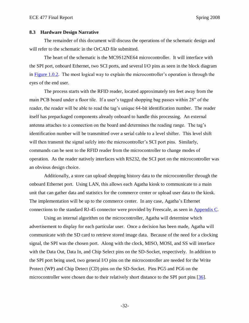
8.3 Hardware Design Narrative
The remainder of this document will discuss the operations of the schematic design and
will refer to the schematic in the OrCAD file submitted.
The heart of the schematic is the MC9S12NE64 microcontroller. It will interface with
the SPI port, onboard Ethernet, two SCI ports, and several I/O pins as seen in the block diagram
in Figure 1.0.2. The most logical way to explain the microcontroller‟s operation is through the
eyes of the end user.
The process starts with the RFID reader, located approximately ten feet away from the
main PCB board under a floor tile. If a user‟s tagged shopping bag passes within 28” of the
reader, the reader will be able to read the tag‟s unique 64-bit identification number. The reader
itself has prepackaged components already onboard to handle this processing. An external
antenna attaches to a connection on the board and determines the reading range. The tag‟s
identification number will be transmitted over a serial cable to a level shifter. This level shift
will then transmit the signal safely into the microcontroller‟s SCI port pins. Similarly,
commands can be sent to the RFID reader from the microcontroller to change modes of
operation. As the reader natively interfaces with RS232, the SCI port on the microcontroller was
an obvious design choice.
Additionally, a store can upload shopping history data to the microcontroller through the
onboard Ethernet port. Using LAN, this allows each Agatha kiosk to communicate to a main
unit that can gather data and statistics for the commerce center or upload user data to the kiosk.
The implementation will be up to the commerce center. In any case, Agatha‟s Ethernet
connections to the standard RJ-45 connector were provided by Freescale, as seen in Appendix C.
Using an internal algorithm on the microcontroller, Agatha will determine which
advertisement to display for each particular user. Once a decision has been made, Agatha will
communicate with the SD card to retrieve stored image data. Because of the need for a clocking
signal, the SPI was the chosen port. Along with the clock, MISO, MOSI, and SS will interface
with the Data Out, Data In, and Chip Select pins on the SD-Socket, respectively. In addition to
the SPI port being used, two general I/O pins on the microcontroller are needed for the Write
Protect (WP) and Chip Detect (CD) pins on the SD-Socket. Pins PG5 and PG6 on the
microcontroller were chosen due to their relatively short distance to the SPI port pins [36].

ECE 477 Final Report Spring 2008
-33-
The image data will be transferred through the microcontroller‟s second SCI port to a
level shifter. This serial connection will connect to the SLCD module, which will accept the
image data and buffer it to the 5.7” LCD screen integrated into the module. The SLCD runs
through an RS-232 SCI interface and includes ample amounts of documentation.
A push button near the LCD screen will allow the user to interact with the LCD display.
A general purpose I/O pin, PG0, was chosen to keep all of the I/O pins organized close together
on the microcontroller. Since this push button will be several feet away from the PCB board, it
is optically isolated from the rest of the circuit.
Status LED‟s fill the rest of the PG port pins (PG1-PG4) using them as general I/O‟s. For
example, an LED may signal when a tag is read, when an image is selected, or when an image is
being displayed. The use of these LED‟s will help with debugging and servicing the Agatha
kiosk.
Finally, an external crystal oscillator and the background debug headers are connected to
the microcontroller. The values and arrangements of the passive components were suggested by
the Freescale document in Appendix C and will meet the needs of the project. An external reset
push button has been added for easy reset.
8.4 Summary
Agatha‟s hardware design is compact and centralizes around the MC9S12NE64
microcontroller. The SPI port, both SCI ports, and the onboard Ethernet are all the peripherals
utilized on the microcontroller. Conveniently, all of the components that will be located on the
PCB board can safely run off 3.3V, eliminating the need for DC-DC or other converters [4]-[5],
[7], [23], [36]. Agatha‟s schematic follows many of the recommendations from the
manufacturers, as seen below in the Appendixes. The design also includes status LED‟s to help
with debugging and servicing the project. Agatha‟s hardware design meets all of the needs to
perform to the team‟s specifications.

ECE 477 Final Report Spring 2008
-34-
9.0 PCB Layout Design Considerations
9.1 Introduction
The development of our PCB was an iterative process that placed and replaced
components and traces based on a number of requirements. Organized component placement and
signal routing was a major concern. As more traces were routed, additional factors like power,
interference, and component sensitivity became factors as well. Numerous redesigns with these
factors in mind led to a safe and well-spaced layout.
9.2 PCB Layout Design Considerations – Overall
The PCB layout evolved naturally out of the design schematic [Appendix C].
Components are generally placed relative to their location on the microcontroller. By placing
components in this manner we reduce the complications of longer traces and the need for
additional vias. This should not to suggest that component placement was straightforward, and
several design iterations were required to develop an organized, well-spaced layout that satisfies
device requirements.
A number of components in our design use a large amount of power, in particular the
5.7” LCD and the RFID reader, but these components are not located on or powered by the PCB.
In fact, PCB is not expected to consume large amounts of power- far less than the 2A provided
by the voltage regulator [37] - and uses 60 mil power and ground traces. This exceeds the
absolute minimum width of 40 mils [38]. Logic traces are drawn 12 mils wide, a suitable size for
these low-power signals. The device is not intended for operation above or below room
temperature, so resistance at extreme operating temperatures was not considered.
The Freescale 9S12NE64 microcontroller is placed near the top center of the board for
convenient access to power, ground, and the peripheral devices it integrates. Careful attention
was given to fanning out signals as much as possible from the microcontroller. Our notes
recommend a minimum spacing of 12 mils, but our signals are spread much further wherever
possible. Spreading these signals intends to reduce interference and became an influence on
component selection and placement. The GPIO header, for example, was reduced from 20 pins
to 10 pins to facilitate a greater fan out.

ECE 477 Final Report Spring 2008
-35-
The Ethernet controller is one of the more sensitive components in our design and can
easily be affected by interference. Close attention was paid to the Freescale 9S12NE64 PCB
design recommendations. Large portions of our PCB were designed with the Ethernet controller
in mind to minimize harmful effects. For example, the power and ground traces, originally at the
top right of the board, were moved to the lower left to avoid the Ethernet components.
Differential RX and TX pairs are drawn in short (about 1”), straight traces from the
microcontroller to the RJ45 jack. The differential pairs are the only exceptions to the fan out
rules followed for most signals: these signals are kept as close together as possible, about 10
mils. The sets of pairs, however, are kept as far apart as possible. These signals are kept at nearly
equal lengths [7].
In order to avoid vias, the RJ45 jack is mounted to the bottom of the PCB rather than the
top. The pins from the microcontroller do not correctly correspond to the pins on the RJ45 jack,
but are actually entirely reversed. Mounting the jack to the bottom reduces wiring complexity
and does not add any significant difficulty to PCB or package manufacturing.
The Max3322 level shifter and RS232 jacks were placed at the bottom of the board. The
RS232 jacks need to be placed off the edge of the board, and because of the placement of the SCI
pins on the Freescale 9S12NE64, the bottom portion of the board is a convenient place for these
devices. Like the RJ45 jack, the Max3322 level shifter was placed on the bottom of the board
because its TTL level input and output signal pins are opposite to their corresponding pins on the
microcontroller. On the bottom of the PCB, the signals require fewer vias and, as the RS232
jacks are through-hole devices, the Max3322 can connect its RS232 jacks without vias. Bottom
placement also conveniently lines up the signals to an SCI header used for debugging.
Decoupling capacitors for the Max3322 were selected and placed and placed as close to the chip
as possible, as per the manufacturer‟s specification [23].
The SD card reader, accessed through the SPI module, is not mounted on the PCB but is
instead connected through an SPI header. This configuration saves board space, eliminates a
complicated network of traces and vias, improves debugging support, and is likely more suitable
to the product‟s packaging.
A 10-pin header located on the top left of the board provides connections to additional
general-purpose I/O pins. Their use is not yet defined, but provide options for debugging,
additional input, or backup pins in the event that a part of the board breaks or fails to function.

ECE 477 Final Report Spring 2008
-36-
9.3 PCB Layout Design Considerations - Microcontroller
The microcontroller layout followed the PCB design recommendations provided in
Appendix B of the Freescale 9S12NE64 data sheet [7]. Decoupling capacitors are connected as
near as possible to their corresponding supply pairs, either directly to the side or underneath the
microcontroller. Aside from these capacitors, no other signals are run underneath the
microcontroller in order to avoid interference. The same attention is paid to the oscillator circuit:
the oscillator was kept on the top of the board as close to the microcontroller as possible, and no
power traces or signals are routed beneath.
Power traces are routed to avoid crossing certain sections of the microcontroller. The
microcontroller requires power and ground connections from all sides, but sensitive circuits, like
the Ethernet and the oscillator circuit, limit the options of large power traces. 30 mil power and
ground traces are provided where convenient and appropriate. The microcontroller is kept to the
right of the power and ground traces, and VCC and VDD pins from the top, left, and bottom
were routed with little difficulty. To avoid interference with the Ethernet and oscillator circuits,
supply pins from the right side are routed to decoupling capacitors underneath the
microcontroller.
9.4 PCB Layout Design Considerations - Power Supply
The power supply was designed with the criteria in mind to provide power to all
necessary components while not interfering with signals or creating loops. The device is not
expected to draw large quantities of power, so power and ground traces are drawn 60 mils wide.
At 90 degrees F, a 60 mil trace can allow a maximum amperage of 2.248A, which is well above
our current requirements. The largest power trace on the board is less than 8” in length. 60 mil
copper traces have a resistance of .00466 ohm/in [39]. Even at the maximum 2A current, this is a
drop of .07V.

ECE 477 Final Report Spring 2008
-37-
At These traces often taper to 30 mils when reaching a component likely to use a good
deal of power, and taper again to certain components- in particular ICs- with smaller pins.
The main traces are drawn near each other, as recommended in the Motorola AN1259
Application Note [40], and placed on the left side of the board. This area is reserved for non-
critical components like surface mount LEDs and GPIO. By routing power and ground from top
to bottom and branching off where necessary, we avoid loops that could result in EMI. Wherever
possible, power traces avoid routes underneath or parallel to signals or other components. More
sensitive circuits, like Ethernet and the oscillator, are intentionally avoided [38]. Smaller power
and ground traces sprout out where necessary for individual components.
The Freescale 9S12NE64 and the Max3322 both connect to the ground traces through
bypass capacitors. Where possible, capacitors are placed to sit between and as close as possible
to these traces their respective component. Shorter trace length reduces interference. Larger
traces, 30 mils, are routed when connecting larger groups of bypass capacitors.
All components on the device operate at 3.3V, only a single network of power traces is
routed. This network is kept regulated by a Fairchild KA278R33 low dropout voltage regulator
[37]. This component can provide up to 2A at 3.3V, which is well above our current
requirements.
A surface-mount fuse is attached near the power header to protect the device from shorts.
Both of these devices are located close to the power headers.
9.5 Summary
The pin configuration of the microcontroller and organization of the device schematic
helped to guide the general component placement, and a number of significant design choices
were made to accommodate these components‟ requirements. Safely routing power, ground, and
logic traces to avoid sensitive components, interference, and overall confusion became an
iterative process leading to a clean and well-spaced PCB. Apart from the maximum size of 60
in2, the design was not limited by size, but efforts were made to make the best possible use of our
area.

ECE 477 Final Report Spring 2008
-38-
10.0 Software Design Considerations
10.1 Introduction
Agatha is designed to display a personal targeted advertisement to a user in a public
environment like a shopping center. The advertisement will be chosen based on past information
collected about the user. Agatha consists of a Freescale microcontroller interfaced with an SCI
RFID reader, an SCI Reach SLCD screen, an SPI SD Card, and an RJ-45 Ethernet Jack. The
software running on the microcontroller will allow the advertisement to be selected and
displayed to the targeted viewer and will allow better product placement for advertisers.
10.2 Software Design Considerations
Agatha‟s software design is focused around two primary goals: a fast advertisement
output time, and a database capable of being updated. In order for the user to view the
advertisement selected for them to view it will have to be displayed quickly before they are out
of the area, and therefore this makes it critical for Agatha to be able to select and display the
advertisement quickly. In order to display new and different advertisements and to log the habits
of the viewers, Agatha must be able to update the database of advertisement and shoppers.
Freescale's Codewarrior, utilizing Processor Expert, is allowing us to design our implementation
that encompasses these design criteria.
10.2.1 Mappings of Memory
The MC9S12NE64 microcontroller will be using the normal single chip memory mode
with an active BDM as described in the picture below. Static data and code will be stored in the
64KB of on board flash [7]. The variable, stack, and heap will be stored in the 8 KB of RAM on
the microcontroller [7]. Due to the limited amounts of memory available, appropriate coding
methods are in place. Codewarrior is handling initial memory mapping. Ram intensive functions
such as large libraries and recursive routines will be avoided. The code is being written with the
space constraint in mind, and no problems are expected.

ECE 477 Final Report Spring 2008
-39-
Figure 10.2.1 – Memory Map of the MC9S12NE64
10.2.2 External Interfaces
The microcontroller is interfaced externally through the SCI lines to a MAX3322 level
shifter for the two RS232 interfaces, the SLCD and the RFID. It is also interfaced through the
SPI bus to an SD card. One general purpose I/O pin is used to interface with a pushbutton that
has been optically isolated, 4 general purpose I/O pins are connected to LEDs for use as status
and debugging LEDS, and ten more GPIO are pinned out to a header for use in unforeseen
circumstances. A BDM connector is also attached to the microcontroller to aid in the
programming and debugging process. The SLCD runs almost entirely of its own software.
Simple commands will be sent to it to display different advertisements or to adjust the
advertisement currently displayed [4]. The SD Card is controlled through specific commands for
the SD protocol [41]. The first step involves an initialization sequence of many blank cycles then
a reset to SPI command. This can then be followed by read and write commands. The entire
time while communicating with the SPI the SS line must be held low [41]. The Pushbutton will
trigger an interrupt allowing the microcontroller to determine that user input has occurred.

ECE 477 Final Report Spring 2008
-40-
Table 10.2.2 – External Interfaces
Port Description
PG0 Optically Isolated Pushbutton
PG1 - PG4 Status LEDs
SPI_SS, SPI_SCK,
SPI_MOSI, SPI_MISO
SD Card
SCI1_TxD,SCI1_ RxD SLCD on RS232
SCI0_TxD,SCI0_ RxD RFID on RS232
BKGD, Reset Background Debug Mode
10.2.3 Integrated Peripherals
Agatha uses the built in Ethernet controller for interfacing with the RJ45 connector. The
Ethernet controller has two built in receive buffers to enable us to begin receiving as soon as the
information is sent and deal with the buffer was it is more convenient. All operating modes and
initializations for registers are handled by Freescale's Codewarrior and processor expert. This
simplifies the application coding greatly as the assembly and the register selection is generated
by Codewarrior.
10.2.4 Application Code
Agatha main detection method is through a polling loop. It polls the SCI buffer to detect
new RFID tags indicating new users in the area. It also polls the interrupt flags generated by the
pushbutton and the Ethernet. If these flags are set the application goes off on side tangents to
deal with specific instance. Most of the time Agatha should be doing nothing but detecting new
RFID tags and displaying the advertisements, and in peak traffic times it is possible for Agatha
to be detecting many tags a minute and most of those need to be ignored for the time being. It is
not important for the controller to be available for other things and if the RFID detection was
interrupt driven and not polled then in situations where many tags are being detected, or one tag
is being detected repeatedly, the interrupt will slow done the processing and delay the display of
the personalized advertisement. It is these reasons that Agatha is controlled in a polling loop.

ECE 477 Final Report Spring 2008
-41-
10.3 Software Design Narrative
Main()
Controls the flow of the program, the execution of different bits of code. Starting point
with initializations. Outlined.
List_Dir()
Contains some translations for the Fat16 file commands. Allows the microcontroller to
interface with a formatted SD Card and list the files on the SD Card. Useful for detecting
the pictures and user data stored on the SD Card. Outlined and Needs a little more
Research.
Open_Send()
Contains some translations for the Fat16 file commands. Allows the microcontroller to
interface with an SD card and open the picture to send it to the SLCD. Useful for getting
the pictures from the SD card to the SLCD. Outline and Needs a little more Research.
Screen_Update()
Sends the commands to the SLCD in order to update the screen with new advertisements,
etc. Useful for changing the screen. Written and mostly tested.
RFID_Poll()
Obtains an RFID address from the Rx buffer, if there is one, and checks to make sure it is
new and complete, and then is in charge of processing with the personal advertisement
algorithm. Useful for obtaining RFID addresses from the RFID reader and picking out
and advertisement. Partially Written and Tested rest Outlined.
Check_Interrupts()
Checks the interrupt flags to see if an interrupt occurred. Outlined but not Written.

ECE 477 Final Report Spring 2008
-42-
Data_Update()
Updates the user database with new information from the Ethernet or from Detection.
Writes the data back to the SD Card. Useful for updating the User interface. Partially
Written rest Outlined.
Picture_Update()
Updates the picture database with new information from the Ethernet. Writes the data
back to the SD Card and the SLCD. Useful for adding pictures. Partially Written rest
Outlined.
Push_Button()
Displays the map or other user requested information. Useful for displaying information
upon request. Outlined but not Written.
Timer_Wait()
Waits for approximately 60 seconds. Useful for pausing. Written and tested.
Ethernet_RCV()
Reads the data of off the Ethernet buffer. Useful for getting things from other nodes.
Outline and Needs a little more Research.
SPI_Send()
Sends Data on the SPI line to the SD Card. Useful for writing to the SD Card. Partially
Written rest outlined.
SPI_Recv()
Receives Data on the SPI line from the SD Card. Useful for reading to the SD Card.
Partially Written rest outlined.

ECE 477 Final Report Spring 2008
-43-
SCI_Send()
Sends Data on the SCI line to the SLCD or RFID. Useful for updating the SLCD. Written
and tested.
SCI_Recv()
Receives Data on the SCI line from the RFID or SLCD. Useful for interpreting the return
codes of the SLCD and getting RFID codes. Written and tested.
10.4 Summary
Agatha is primarily a polling loop for the RFID detection, but does utilize two interrupts
to detect incoming data which are detected in the polling loop. Agatha interfaces primarily with
an RFID reader, the SLCD reader, the SD card, and an Ethernet interface. Codewarrior handles
most of our initializations and memory management. It stores the code in flash and sets the
dynamic data to be store in system memory.
11.0 Version 2 Changes
Agatha 2.0 would feature many new changes to enhance the overall experience of the
system.
First, Agatha 2.0 would have a much larger display. Instead of settling for a small LCD
display, a graphics controller would be able to output advertisement images to a TV display.
This would allow more space to be taken up by a screen display on the kiosk. This would also
make the overall cost of Agatha go down.
Secondly, a new FAT file system would be implemented to make it easier to index all of
the stored data on the external SD card, including the USERDATA file, as well as the stored
images. Additionally, this would make it easier for another feature to be added, Ethernet
capability. Ethernet would make it possible for store data and user preferences to be
instantaneously updated when a purchase is made at a store, instead of manually taking the SD
card out and uploading data via a card reader. This process would make Agatha even more
effective in targeting advertisements.

ECE 477 Final Report Spring 2008
-44-
Lastly, a new and easy feature to add would be making the RFID reader wireless.
Currently, Agatha‟s RFID reader must be placed underneath a floorboard. Additionally, the
serial cable linking the reader to the kiosk must be run underground, making installation difficult.
Sending the RFID tag ID‟s wirelessly would make the process much easier for the end user
without drastically increasing the costs.
12.0 Summary and Conclusions
During this sixteen week course, Agatha‟s design team has designed and manufactured a
product through all phases of the design process. Ever since its initial conception, Agatha has
been about pushing boundaries. Targeted advertising is not a new idea, but Agatha implements
this idea in a totally groundbreaking way. During the design, the team pushed itself to complete
all five of the success criteria, even adding extra features, like a map display, real
troubleshooting features, and packaging designed with the end user in mind.
Pushing the boundaries gave the team an unforgettable experience, which fused all of the
team‟s strengths and skills gathered through college and life. Even when the PCB board became
buggy, serial lines refused to receive data, or images displayed corrupted, the design team
focused and was able to complete a highly quality and successful product. The process was
rewarding and the Agatha design team could not have dreamed of a better finished product or
end to our Purdue undergraduate career.

ECE 477 Final Report Spring 2008
-45-
13.0 References
[1] eMarketer, “2.1 Billion Behaviorally targeted Ad Market by 2008,” [Online Article],
2006, [cited 14 April 2008], Available:
http://www.marketingvox.com/emarketer_21_billion_behaviorally_targeted_ad_market_
by_2008-021581/.
[2] iAutomate, “Long range RFID Reader for Asset Management Model R500 SP,” [Online],
2005, [cited 28 January 2008], Available: http://www.iautomate.com/r500sp.html.
[3] Texas Instruments Incorporated, “S4100 Multi-Function Reader Module Data Sheet,”
[Online document], 2003, [cited 28 January 2008], Available:
http://www.ti.com/rfid/docs/manuals/refmanuals/rf-mgr-mnmn_ds.pdf.
[4] Reach Technologies, “SLCD Controller Board,” [Online], 2007, [cited 28 January 2008],
Available: http://www.reachtech.com/display/slcd.html.
[5] Intersoft Corp., “WM-RO-LR,” [Online document], February 2002, [cited 28 January
2008], Available: http://www.intersoft-us.com/dnload/wmrolr.pdf.
[6] Intersoft Corp., “Passive Read-only RFID Tags,” [Online document], 2005 November,
[cited 28 January 2008], Available: http://www.intersoft-us.com/dnload/pasrotag.pdf.
[7] Freescale Semiconductor, “MC9S12NE64,” [Online Document], 2004, [cited 28 January
2008], Available: http://www.freescale.com/files/microcontrollers/doc/fact_sheet/
MC9S12NE64FS.pdf.
[8] Google, “Google Milestones,” [Online], 2007 [cited 28 January 2008], Available:
http://www.google.com/corporate/history.html.
[9] Montalbano, “Microsoft Helps Put Ads on Computerized Shopping Carts,” IDG News
Service, PC World, [Online], 16 January 2008, [cited 28 January 2008], Available:
http://www.pcworld.com/article/id,141394-c,adsvisitortracking/article.html.
[10] Intersoft Corp., “Ordering Step 1/3,” [Online], 2007, [cited 28 January 2008], Available:
https://www.intersoft-us.com/cgi-bin/order1.pl.
[11] Microchip Technology Inc., “PIC24FJ64GA010,” [Online], 2007, [cited 28 January 2008],
Available: http://www.microchip.com/stellent/
idcplg?IdcService=SS_GET_PAGE&nodeId=1335&dDocName=en024811.
[12] Texas Instruments, Inc., “16-bit fixed point DSP with Flash – TM320LF2407A,” [Online],
2008, [cited 28 January 2008], Available: http://focus.ti.com/docs/prod/folders/print/
tms320lf2407a.html.

ECE 477 Final Report Spring 2008
-46-
[13] Atmel, “32058S,” [Online document], October 2007, [cited 28 January 2008], Available:
http://atmel.com/dyn/resources/prod_documents/32058S.pdf.
[14] Intersoft Corp., “WM-RO-MR2,” [Online document], November 2000, [cited 28 January
2008], Available: http://www.intersoft-us.com/dnload/wmrolr.pdf.
[15] Skyetek, “SkyeModule M9,” [Online document], 2007, [cited 28 January 2008], Available:
http://www.skyetek.com/Portals/0/Documents/Products/SkyeModule_M9_DataSheet.pdf.
[16] EarthLCD, “ezLCD-001,” [Online], unknown date, [cited 28 January 2008], Available:
http://store.earthlcd.com/LCD.
[17] Baluja, Shumeet, “Allocating Advertising Space in a Network of Displays,” [Online], 20,
June 2005, [cited 24 March 2008], Available: www.pat2pdf.org/patents/pat20060287913.
[18] Brice, David George; Carpenter, Steve, “Media Enabled Advertising Shopping Cart
System,” [Online], 1 December 2005, [cited 25 March 2008], Available:
http://www.google.com/patents?id=nI6XAAAAEBAJ&dq=shopping+cart+rfid.
[19] Frick, Oliver; Kubach, Uwe; Schaper, Joachim, “RFID Activated Information Kiosk,”
[Online], 29, August 2003, [cited 24 March 2008], Available:
http://www.google.com/patents?id=0TyJAAAAEBAJ&dq=rfid+kiosk.
[20] Department of Defense, “MIL-HDBK-217F Military Handbook: Reliability Prediction of
Electronic Equipment,” 2 December 1991. [Online]. Available:
http://cobweb.ecn.purdue.edu/~dsml/ece477/Homework/CommonRefs/Mil-Hdbk-217F.pdf
[Accessed: 3 April 2008].
[21] Fairchild Semiconductor, “KA78RXXC-Series,” 2003. [Online]. Available:
http://www.fairchildsemi.com/ds/KA%2FKA78R05C.pdf [Accessed: 3 April 2008].
[22] Freescale Semiconductor, “MC9S12NE64 Data Sheet,” June 2006. [Online]. Available:
http://www.freescale.com/files/microcontrollers/doc/data_sheet/MC9S12NE64V1.pdf?pspl
l=1 [Accessed: 3 April 2008].
[23] Maxim Integrated Products, “Reliability Report for MAX3323ExxE Plastic Encapsulated
Devices,” 18 April 2003. [Online]. Available: http://www.maxim-
ic.com/reliability/maxim/MAX3323ExxE.pdf [Accessed: 3 April 2008].
[24] Printed Circuit Board Manufacturing, International Network for Environmental
Compliance and Enforcement, [Online Document], July 2002, [cited 9 April 2008],
Available: http://inece.org/mmcourse/chapt7.pdf
[25] Toxic Substances, Environmental Protection Agency, [Online Document], 25 Oct 2007,
[cited 9 April 2008], Available: http://www.epa.gov/lead/index.html

ECE 477 Final Report Spring 2008
-47-
[26] Intermec Education Services. Understanding RFID – Educational Video. [cited 9 April
2008] Available: http://rfident.org/rfidvideo.htm
[27] DIRECTIVE 2002/95/EC OF THE EUROPEAN PARLIAMENT AND OF THE
COUNCIL of 27 January 2003 on the restriction of the use of certain hazardous substances
in electrical and electronic equipment [Online Document], 27 January 2003, [cited 9 April
2008] http://eur-lex.europa.eu/LexUriServ/LexUriServ.do?
uri=OJ:L:2003:037:0019:0023:EN:PDF
[28] Katherine Albrecht and Liz McIntyre, “Part 2: The Shopping Cart of the Future?,”
[Online], 2003-2006, [cited 4 February 2008], Available:
http://www.spychips.com/metro/albrecht-tour-2.html
[29] David A. Utter, “RFID Billboards Target Mini Audience,” [Online], 2007, [cited 4
February 2008], Available: http://www.webpronews.com/insiderreports/2007/01/12/rfid-
billboards-target-mini-audience
[30] Conrad Quilty-Harper, “Google plans street advertising presence,” [Online], 2007, [cited 4
February 2008], Available: http://www.engadget.com/2007/01/11/google-plans-street-
advertising-presence
[31] Patent Storm, “Shopping Cart with RFID capability,” [Online], 2007, [cited 4 February
2008], Available: http://www.patentstorm.us/patents/7225980-claims.html
[32] Bill Slawski, “Google Magazine – About Whatever You Want (Soon at a Kiosk Near You),
“[Online], 2005-2008, [cited 4 February 2008], Available:
http://www.seobythesea.com/?p=894
[33] US Patent & Trademark Office, “United States Patent Application: 0060287913,” [Online],
2006, [cited 4 February 2008], Available: http://appft1.uspto.gov/netacgi/nph-
Parser?Sect1=PTO2&Sect2=HITOFF&u=%2Fnetahtml%2FPTO%2Fsearch-
adv.html&r=1&p=1&f=G&l=50&d=PG01&S1=20060287913.PGNR.&OS=dn/200602879
13&RS=DN/20060287913
[34] Ziff Davis Enterprise Holding Inc., “Linux gas pump prints Google Maps,” [Online], 2007,
[cited 5 February 2008], Available:
http://www.linuxdevices.com/news/NS6114899281.html
[35] Josh Catone, “Coming to a Gas Pump Near You: Google,” [Online], 2007, [cited 5
February 2008], Available: http://www.readwriteweb.com/archives/google_gas_pump.php
[36] 4UConn Technologies, “SD-Socket,” [Online Document], 26 July 2005, [cited 14 February
2008], Available: http://www.sparkfun.com/datasheets/Prototyping/SD-Socket-PP-
14446.pdf.

ECE 477 Final Report Spring 2008
-48-
[37] Fairchild Semiconductor, “KA278RXXC-Series 2A Output Low Dropout Voltage
Regulators,” [Online Document], 2005, [cited 21 February 2008], Available:
http://www.fairchildsemi.com/ds/KA/KA278R05C.pdf
[38] Meyer, D.G., “PCB Fabrication Process and Layout Basics,” [Online Document], 2007,
[cited 20 February 2008], Available:
http://cobweb.ecn.purdue.edu/~dsml/ece477/Notes/PDF/Mod9.pdf
[39] Joez Garage, “PCB Trace Amperage Chart,” [Online Document], [cited 21 February 2008],
Available: http://www.joezgarage.com/PCB%20Trace%20Width%20Calculator.htm
[40] Motorola, “Application Note AN1259: System Design and Layout Techniques for Noise
Reduction in MCU-Based Systems,” [Online Document], 1995, [cited 21 February 2008],
Available:
http://cobweb.ecn.purdue.edu/~dsml/ece477/Homework/CommonRefs/AN1259.pdf
[41] SD Group “SD Specifications” 25 September 2006 [Online] Available:
http://freescalemcu.com/samples/Simplified_Physical_Layer_Spec.pdf [Accessed 18 March
2008]

ECE 477 Final Report Spring 2008
-49-
Appendix A: Individual Contributions
A.1 Contributions of Ian Bacon:
Ian Bacon's contribution to the Agatha project was diversely distributed throughout the entirety.
Ian helped with almost all of the phases of the project from part selection to final testing, but he
focused and spent considerable time on particular parts such as component interfacing, software
design and PCB routing. Ian also spent time managing the production and attempting to keep
organization in the software.
Some of the smaller areas Ian worked on were part research, package construction,
and presentations. Ian was working with the team to research appropriate parts to find
components to fit the design as well as change the design to fit the components we could find. A
lot of initial research was focused in the graphics controller area. In the package construction Ian
constructed the frame for the RFID antennae. He also helped in the painting of the final box.
Component interfacing was a big area of Ian's work in the production of Agatha. All
of the parts had to be able to talk to each other. The biggest amount of time interfacing
components was spent trying to link the SD card through the SPI to the micro controller. Ian had
to learn a new system of commands the SD card uses for transfers. Some time was also spent
attempting to interface with the Ethernet connection. Ian explored some software using the
OpenTCP interface to work with the Ethernet connection.
Software design was probably the biggest area of Ian's focus during the semester. A
lot of software was written for the different phases of the project. The software phases that Ian
worked on were initial familiarization, functionality tests, and final coding. During all of these
phases Ian produced different types of software to benefit the product. In the initial stage most of
the code was oriented around familiarization with the software development tools and the
development board. Ian wrote many little small programs to control different functions on the
board such as a printing on the SCI, using timer interrupts, and basic SPI functionality. In the
next stage, the functionality tests, the goal was to prove that all of the features we need to use
will work on the development board at least. Ian wrote many debug functions in this stage. A lot
of conversion functions and specialized print functions were written to be able to display
meaningful messages and numbers to the screen. In the final stage of production Ian wrote parts

ECE 477 Final Report Spring 2008
-50-
of the software that will run on the final design. Parts focused on were the selection algorithm
and the control loop.
One of the last areas of focus that Ian had in the design project was Project
Management. A lot of time was spent organizing in order to make the teams efforts more
productive. Simple tasks like cleaning the lab bench and much more complicated tasks such as
code organization were all performed. Ian took code that the he and others wrote and converted it
into useful and more legible functions. In the process he also cleaned it up making use of more
appropriate methods that had been learned after the original part had been written. This was done
several times over the course of the whole project.
Ian Bacon worked well with his team accomplishing his fair share of the work and
completing the tasks assigned to him. He spent some of his time with the group achieving
objectives as a team, as well as spending time on his own to accomplish things that would benefit
the group as a whole. He tried to be assist in all areas and focus on some more specific areas. Ian
put in good consistent effort and work during the whole semester long design project.
A.2 Contributions of Zach Dicklin:
Throughout the semester, I have made a number of contributions to all areas of the
project. From the initial design stages to the final presentation, I have attempted to guarantee our
team‟s success as an innovative problem solver, a diligent researcher, and a leader. Most notably,
I applied these qualities to our project‟s initial conception, hardware design, and software
development.
From day one I contributed by sharing a number of possible project ideas and
participating in the brainstorming process. After deliberation and weighing the possible projects
as a group, one of these ideas became the fundamental concept behind our final project.
Following this, I was active in component selection and purchasing by making important
decision for the microcontroller, RS232 level shifter, data storage, and display. I saved our group
several hundred dollars by applying for a free development kit through a Freescale university
program and by negotiating a much cheaper price from the manufacturer of our LCD controller.
During the hardware portions of our project, I was an active participant in our circuit
schematic and PCB layout. I spent numerous hours working with my teammates on several
iteration of the PCB design. When our PCB arrived, I continued my contribution to the hardware

ECE 477 Final Report Spring 2008
-51-
by soldering most of the components, including the microcontroller, oscillator, and level shifter.
I built or modified a number of the cables used to connect this board to our peripheral
components.
I was also a hands-on coder during the software development stages. From the early
phase of relearning the Freescale microcontroller to the finished project, I helped guide our
group to each new level of software abstraction. I worked with my team to understand
Codewarrior through trial and error, as well as alone with the Freescale manual to lay the
foundations for interfacing our peripheral devices. After several weeks researching and
interfacing the SD card using the SPI, I made key steps in our implementations of the FAT file
system, data transfer, and advertisement selection algorithm. When work was done
independently, I made deliberate efforts to inform my teammates of the additions or changes I
made in their absence, in particular by employing a running, physical lab notebook used
religiously by each team member.
Through my contributions to our project‟s initial concept, hardware design, and software
development, I feel I have played a critical role in our team‟s success. Though we have faced
some failures, I am proud of our team‟s achievements.
A.3 Contributions of Amy Ritter:
Throughout the project, I have contributed in every step that I could to help the project
succeed. I have tried my best to understand what is going on through each change to the PCB
footprint, the schematic, and coding choices. With the help of the rest of the team, we have
succeeded in making a working final project. Throughout the course, I have contributed in
helping pick an RFID reader, create a schematic, design the user manual, understand Ethernet,
coding assistance, and finally the overall construction of the kiosk.
The RFID reader was a difficult part to find because the team did not really know what
kind to get and the differences between the various choices found on the Internet. At first, I
looked at the differences between active and passive readers and which would benefit the
project. I decided on a passive reader to read passive tags because the tag would be inside the
shopping bags of the customers and would need some power for the tag to be read by the reader.
From here, I looked into some RFID readers from Texas Instruments and Intersoft and finally
settled on a relatively inexpensive reader from Intersoft that included the antennae in the price.

ECE 477 Final Report Spring 2008
-52-
Next, I assisted Eric in creating the schematic for the project. I helped create a new part
for our microcontroller and label the wires out of it correctly so that we could attach new parts to
the design like SCI, SPI, and Ethernet. I pulled up some schematic drawings for the RFID
reader, SLCD screen, and SD card reader to help match the wires from the microcontroller to the
various parts. Finally, I aided in the placement of resistors to these parts including the LED
lights to relay information to the user of its operation.
Subsequently for the user manual, I captured several pictures of the overall design. These
pictures included the front and back of the kiosk along with some pictures of the inside. My
hands were used to model the various parts inside the kiosk including our breadboard and SLCD
screen to help aid the user of the product to understand how to attach the wires correctly.
Finally, I helped in reviewing the user manual to see if the user would be able to correctly setup
and use our product.
Following this some new knowledge about Ethernet was needed for the team. Since the
example microcontroller from Freescale already had Ethernet connections on it and software, I
tested it for its Ethernet capabilities. I setup the circuit in the manual and was able to ping the
device. I tried looking through the code to see how they setup it up and used the Ethernet in
hopes that I could understand how to send and receive UDP packets.
My knowledge of coding from the various classes offered at school has assisted me in
helping code some of the project. I have used my knowledge of C to look over the various
functions that were written and understand them. This allowed me to help when problems arose
to debug the functions and help write new ones in their place. This has led to the project being a
success because it would be nothing with the code working.
My last contribution to the project included helping in the construction of the kiosk. I
helped paint the outside of it white to help showcase its appeal to the shoppers‟ eyes. I also
aided in fitting the SLCD screen into the hole that was slightly too small due to the electric cord
and SCI port connections. This led to an expansion of the hole slightly by taking a chisel to the
inside to make room.

ECE 477 Final Report Spring 2008
-53-
A.4 Contributions of Eric Yee:
As the only electrical engineer on the team, I focused on component selection, hardware
design, kiosk design, and documentation. Even with these “specific tasks,” the team operated as
one unit and consistently worked together on almost every aspect of the project.
One of the hardest components to locate for the project was the RFID reader. No one on
the team knew much about RFID technology, so I did a lot of research with Amy early on to
determine what would work best for the team. Through our joint research, we located a reader
from Intersoft that provided our three specifications: a reader with 1-2 foot reading range;
availability of compatible, passive tags; and a reasonable price. However, even after finding the
perfect reader, antenna, and tag combination, the company told me that it would take at least four
weeks ship out and another week to arrive. Working with the technical staff, we were able to
choose another reader from the company that would meet our needs and was actually a cheaper
solution!
The other component that was researched was the SLCD screen for the display. Early on,
other team members chose an Epson graphics controller for output to a NTSC TV display.
However, I researched simultaneously an LCD controller that was used by previous ECE477
groups. I contacted one of the team members who had used the SLCD screen for information
and gathered information that led to the decision to use the chip. Extra care was done on the
component selection to ensure ideal compatibility with operating frequencies and voltage.
The schematic design came next. Again, Amy and I teamed up to create a suitable,
nicely laid out schematic for the project. Because of our excellent selection in parts, the there
was minimal design in the power circuit for the project, often times the hardest part. All of the
components chosen for the PCB board could run safely at 3.3V, and the other external
peripherals could be operated with their own wall warts. Using documentation and linear circuit
analysis, we were able to design a schematic that met the needs of the project.
The whole team aided in the design of the PCB board, which went through eight
iterations. Once the board was manufactured, Zach and I populated the board and ran many tests
to ensure correct operation. I helped in running several of the debugging tests with the software
and PCB board.
While I lent some help in assisting the other computer engineer teammates write the
code, I focused on many of the other aspects, as three of them could easily do better and more

ECE 477 Final Report Spring 2008
-54-
efficient work without me. I focused on the kiosk construction, which was designed in a way for
easy access and usability. A hinged door provided easy access for the internal parts, and a wire
hole on the bottom allowed easy access for wires.
Technical documentation and presentations were also designed by me to help the group
communicate its accomplishments. I think that I successfully was able to communicate our
project to different audiences: technical audiences in the form of the design review report and
presentation; non-technical audiences in the form of the detailed User Manual; and partially
technical Digijocks at the ECE270/362 classes.
The project was a rewarding experience, and I think that our team functioned well in
dividing up the work and sorting out responsibilities. I have learned a great deal about the “real
world” design process.

ECE 477 Final Report Spring 2008
B-1
Appendix B: Packaging
Figure B.1 – Simple sketch of Agatha
Figure B.2 – Dimensions of Agatha

ECE 477 Final Report Spring 2008
B-2
Figure B.3 – Interior parts layout
Figure B.4 – Outer Design
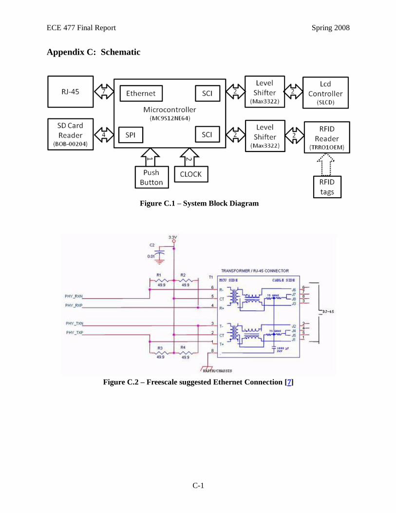
ECE 477 Final Report Spring 2008
C-1
Appendix C: Schematic
Figure C.1 – System Block Diagram
Figure C.2 – Freescale suggested Ethernet Connection [7]

ECE 477 Final Report Spring 2008
C-2
Figure C.3: Maxim MAX3322 suggested configuration [23]
Figure C.4: Freescale suggested configuration (80 pin TQFP) [7]

ECE 477 Final Report Spring 2008
C-3
Figure C.5: Overall schematic view
Figure C.6: Microcontroller and power connection

ECE 477 Final Report Spring 2008
C-4
Figure C.7: Microcontroller and Ethernet
Figure C.8: SCI and SPI pinouts

ECE 477 Final Report Spring 2008
D-1
Appendix D: PCB Layout Top and Bottom Copper
Figure D.1: Top and bottom layer of PCB board design
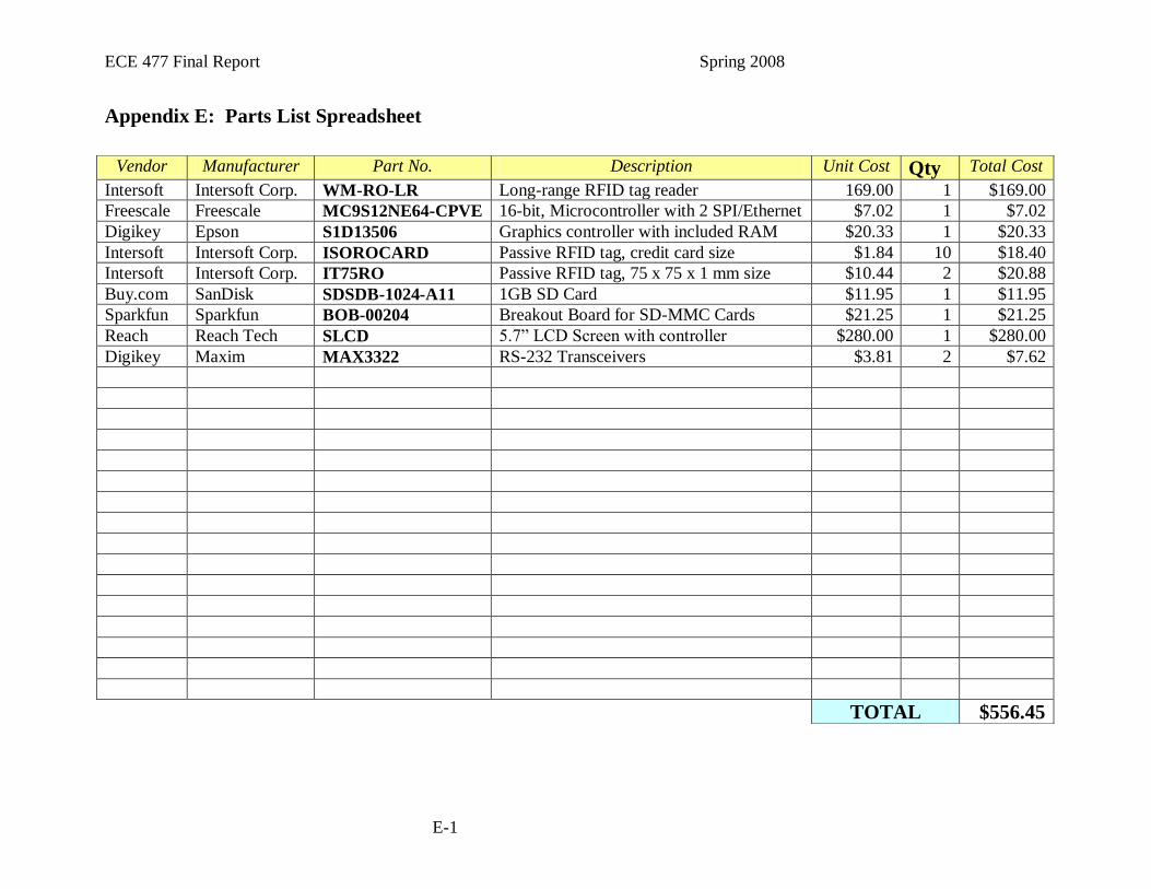
ECE 477 Final Report Spring 2008
E-1
Appendix E: Parts List Spreadsheet
Vendor Manufacturer Part No. Description Unit Cost Qty Total Cost
Intersoft Intersoft Corp. WM-RO-LR Long-range RFID tag reader 169.00 1 $169.00
Freescale Freescale MC9S12NE64-CPVE 16-bit, Microcontroller with 2 SPI/Ethernet $7.02 1 $7.02
Digikey Epson S1D13506 Graphics controller with included RAM $20.33 1 $20.33
Intersoft Intersoft Corp. ISOROCARD Passive RFID tag, credit card size $1.84 10 $18.40
Intersoft Intersoft Corp. IT75RO Passive RFID tag, 75 x 75 x 1 mm size $10.44 2 $20.88
Buy.com SanDisk SDSDB-1024-A11 1GB SD Card $11.95 1 $11.95
Sparkfun Sparkfun BOB-00204 Breakout Board for SD-MMC Cards $21.25 1 $21.25
Reach Reach Tech SLCD 5.7” LCD Screen with controller $280.00 1 $280.00
Digikey Maxim MAX3322 RS-232 Transceivers $3.81 2 $7.62
TOTAL $556.45

ECE 477 Final Report Spring 2008
F-1
Appendix F: Software Listing
/** ###################################################################
** Filename : Agatha.C
** Project : Agatha
** Processor : MC9S12NE64CPV
** Version : Driver 01.12
** Compiler : CodeWarrior HC12 C Compiler
** Date/Time : 4/12/2008, 11:26 AM
** Abstract :
** Main module.
** Here is to be placed user's code.
** Settings :
** Contents :
** No public methods
**
** (c) Copyright UNIS, spol. s r.o. 1997-2006
** UNIS, spol. s r.o.
** Jundrovska 33
** 624 00 Brno
** Czech Republic
** http : www.processorexpert.com
** mail : [email protected]
** ###################################################################*/
/* MODULE Agatha */
#include "Cpu.h"
#include "Events.h"
#include "AS1.h"
#include "AS2.h"
#include "TI1.h"
#include "PE_Types.h"
#include "PE_Error.h"
#include "PE_Const.h"
#include "IO_Map.h"
#include "headers.h"
char block[512];
byte addr_c[4];
char number[6];
char rfid_tag[TAG_LENGTH+1];
char user_pref[PREF_LENGTH+1];
char store_pref[PREF_LENGTH + 1];
int gtimer_limit;
int gtimer_counter;
bool gtimer_flag;
bool gmap_flag;

ECE 477 Final Report Spring 2008
F-2
int scan_users(FileStruct userfile, char *rfid, char *pref){
/* Function searches the user database
* for an rfid tag. If the tag is located, the function
* loads the user_pref global array with the corresponding
* preferences. Otherwise it blanks the array.
*
* Inputs:
* FileStruct userfile user database file information
*
* Outputs:
* int 0 - Tag Not Found
* 1 - Tag Found
*
*/
extern byte addr_c[4];
extern char block [512];
long int file_position = userfile.address;
int i;
char temp_tag[TAG_LENGTH + 1];
temp_tag[TAG_LENGTH] = '\0';
// Loop through the user database file
while(file_position <= userfile.address + userfile.filesize){
// Load block of data
longint_to_addr(file_position, addr_c);
i=SD_ReadBlock(addr_c, block);
// Loop through block
for(i = 0; i < (SECTOR_SIZE / (TAG_LENGTH + PREF_LENGTH + 1)); i++){
if(block[i*16] != 'T'){ // No more tags in databse, return failure
stringcopy("\0\0\0\0\0\0", pref, PREF_LENGTH + 1, 0);
//screen_text("Tag Not Found No More Tags\n");
return -1;
}
if(stringcompare(&block[i*16+1], rfid, TAG_LENGTH)){
// Tag found, copy array and return success
stringcopy(block, pref, PREF_LENGTH, i * 16 + 11);
pref[PREF_LENGTH] = 0;
return 0;
}
}
file_position = file_position + 512;
}
// Tag not found, clear user_pref array
stringcopy("\0\0\0\0\0\0", pref, PREF_LENGTH + 1, 0);
screen_text("Tag Not Found\n");
return -1;
} // scan_users

ECE 477 Final Report Spring 2008
F-3
int find_advert(FileStruct storefile, char *pref){
/* Function determines an appropriate advertisement
* based on the user_pref array and the fields for each
* picture in the store data file.
*
* Store data entries are listed as follows:
* P##CCCCC
* P: Indicates the start of a store data entry
* #: Indicates the picture number as ascii text
* C: Category field
*
* Listing are 8 bytes so that the sector size can be
* divided easily
*
* Inputs:
* FileStruct storefile store data file
*
* Outputs:
* int integer corresponding to an appropriate picture file
*
*/
extern byte addr_c[4];
extern char block [512];
extern char store_pref[PREF_LENGTH + 1];
long int file_position;
int temp;
int i,j;
int end_of_file = 0;
int ad;
int max = 0;
store_pref[PREF_LENGTH] = 0;
//user_pref[PREF_LENGTH] = 0;
pref[PREF_LENGTH] = 0;
screen_clear();
file_position = storefile.address;
screen_text("PSSC 4\n");
screen_text("UserPref: ");
screen_text(pref);
screen_text("\n");
screen_text("Store Pref: \tTotal: \n");

ECE 477 Final Report Spring 2008
F-4
while((file_position < storefile.address + storefile.filesize) && end_of_file == 0){
// Read block
longint_to_addr(file_position, addr_c);
i=SD_ReadBlock(addr_c, block);
// For each entry in the block, identify the maximum category
ad = -1;
max = 0;
for(i = 0; i < (SECTOR_SIZE / 8); i++){
if( block[i*8] != 'P'){
end_of_file = 1; // End of file reached, or corrupt database
//screen_text("EOF\n");
break;
}
else{
stringcopy(block, store_pref, PREF_LENGTH, i*8+3);
temp = 0;
screen_text(store_pref);
screen_text(" \t");
for(j = 0; j < PREF_LENGTH; j++){
temp = temp + ((store_pref[j] - 0x30) * (pref[j] - 0x30));
}
//screen_hex(temp);
//screen_text("\n");
if( temp > max ){
max = temp;
ad = 10 * (block[i*8+1] - 0x30) + (block[i*8+2] - 0x30);
}
}
}
//screen_text("advertisment ");
//screen_hex(ad);
//screen_text(" chosen because max total is ");
//screen_hex(max);
//screen_text("\n");
file_position = file_position + SECTOR_SIZE;
}
//screen_text("AD!!!! Number \"");
//screen_hex(ad);
//screen_text("\" There Was supposed to be an add\n");
return (ad);
}

ECE 477 Final Report Spring 2008
F-5
void Agatha() {
extern char block[512];
extern byte addr_c[4];
extern char number[6];
extern char rfid_tag[TAG_LENGTH+1];
extern char user_pref[PREF_LENGTH+1];
long int address;
int reserved_sectors;
long int sectors_per_fat;
FileStruct File;
extern int gtimer_counter;
extern bool gtimer_flag;
extern int gtimer_limit;
int response;
int auto_ad = 2;
char prev_rfid_tag[TAG_LENGTH+1];
rfid_tag[TAG_LENGTH] = '\0';
user_pref[PREF_LENGTH] = '\0';
prev_rfid_tag[TAG_LENGTH] = '\0';
screen_clear();
#if DEBUG
screen_text("Connected to the Micro\n");
#endif
//Initialize Header and LED Pins
//*********************************************************************************
DDRJ = 0x00; // J Pins set as Input
DDRH = 0x00; // H Pins set as Input
DDRG = 0xFF; // G Pins (LEDs) set as Output
PTG = 0x01; // Power Indicator LED On
//Initialize the SPI and the SD Card
//*********************************************************************************
SPI_Init();
if (SD_Init()) {
#if DEBUG
print("***SD Card Initialization Failed***\n\rIs the Card Inserted?\n\r");
#endif
screen_text("***SD Card Initialization Failed***\nIs the Card Inserted?\n");
for(;;){}
}
#if DEBUG
print("SD card Initialized\n\r");
print("Reading boot sector...\n\r");
#endif

ECE 477 Final Report Spring 2008
F-6
//***********************************************************************************
//Read the Boot Sector
//***********************************************************************************
address = 0;
longint_to_addr(address,addr_c);
if(SD_ReadBlock(addr_c, block)) {
#if DEBUG
print("***Boot Sector Failed***\n\rThis is Bad!\n\r");
#endif
screen_text("***Boot Sector Failed***\nThis is Bad!\n");
for(;;){}
}
//***********************************************************************************
//Check For FAT16 Formating
//***********************************************************************************
stringcopy(block, number, 5, 54);
if(!stringcompare(number,"FAT16", 5)){
#if DEBUG
print("***SD Card Not FAT16 Filesystem***\n\rReformat Card\n\r");
#endif;
screen_text("***SD Card Not FAT16 Filesystem***\nReformat Card\n");
for(;;){}
}
//***********************************************************************************
//Calculate Factors needed for FAT16
//***********************************************************************************
reserved_sectors = block[0x0E];
sectors_per_fat = (block[0x16]&0x00FF) | ((block[0x17] << 8)&0xFF00);
//***********************************************************************************
// Set address to root directory map
//***********************************************************************************
address = reserved_sectors * SECTOR_SIZE;
address = address + sectors_per_fat * SECTOR_SIZE * 2;
//***********************************************************************************

ECE 477 Final Report Spring 2008
F-7
// Find Picture bin File
//***********************************************************************************
#if DEBUG
print("Finding File: ");
print(PICFILE);
print("\n\r");
#endif
File = find_file(address, PICFILE,block,addr_c);
if(File.address == -1){
#if DEBUG
print("File not found!\n\r");
screen_text("File not found!\n\r");
#endif
for(;;){}
}
//***********************************************************************************
//PSSC 3
//print("Sending Binary..\r\n");
screen_text("PSSC 3:\r\n");
screen_text("Sending Binary...\r\n");
screen_send_binary(File, block, addr_c);
screen_pic(1); // Display Splash Screen
screen_text("Binary Complete\n");
for(;;);
gtimer_flag = 0; // Not in timeout mode
gmap_flag = 0;
gtimer_counter = 0;
gtimer_limit = 0;
for(;;){
// TEST #1: Check global timer to see if we are in a timeout mode
if(gtimer_counter > gtimer_limit * 1000){
gtimer_limit = 0; // Reset timer limit
gtimer_flag = 0; // Turn off Wait Flag to indicate we're no longer in stall
mode
gtimer_counter = 0; // Reset global timer counter
}
// TEST #2: Check if global map flag is set
if(gmap_flag == 1){
screen_pic(2);
gtimer_counter = 0; // Reset global timer counter
gtimer_flag = 1; // Turn on Wait Flag to indicate we're in
stall mode
gtimer_limit = MAP_TIMEOUT_LENGTH; // Set timeout length
gmap_flag = 0;
}

ECE 477 Final Report Spring 2008
F-8
// Test #3: Is a Valid RFID Tag Detected?
if(gtimer_flag == 0){
gtimer_flag = 1;
gtimer_limit = RFID_TIMEOUT_LENGTH;
gtimer_counter = 0;
for(;;){
response = wait_for_tag( rfid_tag );
if(response == 1) break;
File = find_file(address, USERFILE, block, addr_c);
if(File.address != -1){
if(scan_users(File, rfid_tag, user_pref)==0){
screen_clear();
File = find_file(address, STOREFILE, block, addr_c);
if(File.address == -1){
#if DEBUG
screen_text("**Advertisement Database Not Found!**\n");
#endif
}else{
screen_pic(find_advert(File,user_pref));
gtimer_flag = 1;
gtimer_limit = VALID_TIMEOUT_LENGTH;
gtimer_counter = 0;
break;
} // if advertisement database found
} else {// if registered tag
#if DEBUG
screen_text("Not a Registered Tag\n");
#endif
}
}else{
screen_text("**User Database Not Found!**\n!");
}// if user database found
}
if(response == 1){
screen_clear();
auto_ad++;
if( auto_ad > MAX_ADS ) auto_ad = 3;
screen_pic(auto_ad);
gtimer_flag =1;
gtimer_limit = AUTO_TIMEOUT_LENGTH;
gtimer_counter = 0;
#if DEBUG
screen_text("RFID Timeout\n\r");
#endif
}
}
}
return;
}

ECE 477 Final Report Spring 2008
F-9
void main(void)
{
/* Write your local variable definition here */
/*** Processor Expert internal initialization. DON'T REMOVE THIS CODE!!! ***/
PE_low_level_init();
/*** End of Processor Expert internal initialization. ***/
/* Write your code here */
Agatha();
/*** Processor Expert end of main routine. DON'T MODIFY THIS CODE!!! ***/
for(;;){}
/*** Processor Expert end of main routine. DON'T WRITE CODE BELOW!!! ***/
} /*** End of main routine. DO NOT MODIFY THIS TEXT!!! ***/
/* END Agatha */
/*
** ###################################################################
**
** This file was created by UNIS Processor Expert 2.97 [03.83]
** for the Freescale HCS12 series of microcontrollers.
**
** ###################################################################
*/
/** ###################################################################
** Filename : headers.H
** Project : Agatha
** Processor : MC9S12NE64CPV
** Compiler : CodeWarrior HC12 C Compiler
** Date/Time : 4/12/2008, 11:26 AM
** Contents :
** User source code
**
** (c) Copyright UNIS, spol. s r.o. 1997-2006
** UNIS, spol. s r.o.
** Jundrovska 33
** 624 00 Brno
** Czech Republic
** http : www.processorexpert.com
** mail : [email protected]
** ###################################################################*/
#ifndef __headers_H
#define __headers_H
#include "Cpu.h"
#include "AS1.h"
#include "AS2.h"
#include "PE_Types.h"
#include "PE_Error.h"
#include "PE_Const.h"
#include "IO_Map.h"
/* END headers */
//Debug Mode 1 = On 0 = OFF
#define DEBUG 0

ECE 477 Final Report Spring 2008
F-10
//Name of the Picture File
#define PICFILE "CATEGORY"
#define USERFILE "USERDATA"
#define STOREFILE "STORDATA"
// #Defines
#define TAG_LENGTH 10
#define PREF_LENGTH 5
#define SPIF 0x80
#define SPTEF 0x20
#define SECTOR_SIZE 0x200
#define MAX_ADS 13
// Timeout Defines
#define MAP_TIMEOUT_LENGTH 5
#define RFID_TIMEOUT_LENGTH 5
#define VALID_TIMEOUT_LENGTH 5
#define AUTO_TIMEOUT_LENGTH 5
//File Structure
typedef struct{
char filename[8];
long int address;
long int filesize;
}FileStruct;
//Functions
void Agatha(void);
void stringcopy(char *input_buf, char *output_buf, int length, int start);
void screen_print(char *s_command);
void screen_clear(void);
void screen_text(char *string);
void screen_send_command(char *command);
void Assert_SPI(void);
void Deassert_SPI(void);
void SPI_Init(void);
byte SPI_Byte(byte transmit);
char SDcmd(char command, byte *addr);
int SD_Init(void);
void longint_to_addr(long int input, byte *output);
int SD_ReadBlock(byte *addr, char *out_array);
int stringcompare(char *str1, char *str2, int length);
FileStruct find_file(long int root_address, char *file_to_find, char *gp_array, byte
*gaddr_c);
void screen_send_binary(FileStruct File, char *gp_array, byte *gaddr_c );
void screen_wait_response(void);
void screen_pic(int pic);
int wait_for_tag(char *rfid_tag);
int scan_users(FileStruct userfile, char *rfid, char *pref);
int abs(int i);
int find_advert(FileStruct storefile, char *pref);
int scan_users(FileStruct userfile, char *rfid, char *pref);
void screen_hex(byte val);
#if DEBUG //These Functions only used in Debug Mode;
void print(char * s_command);
void print_block(char *gp_array,long int base);
void print_hex(byte val);
void print_longint(long int input);
void print_int(long int input);
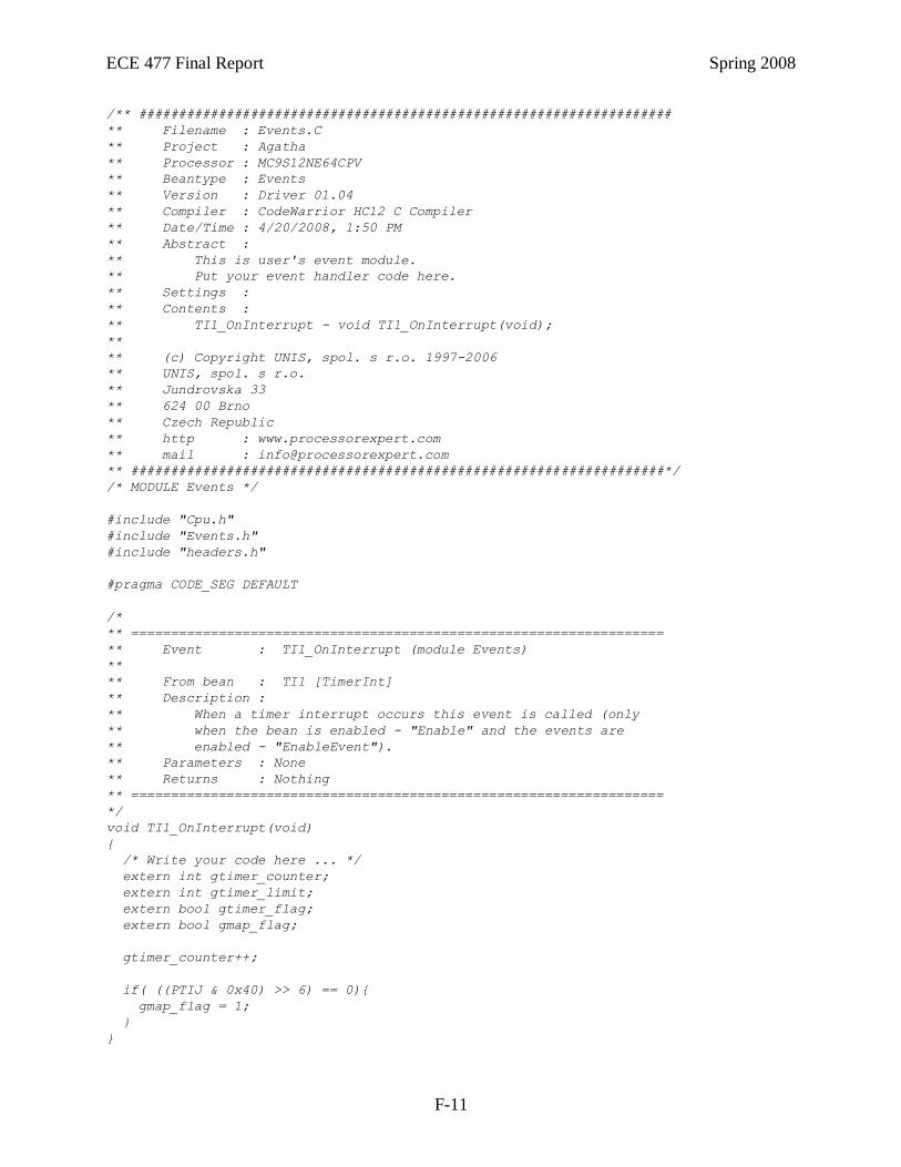
ECE 477 Final Report Spring 2008
F-11
/** ###################################################################
** Filename : Events.C
** Project : Agatha
** Processor : MC9S12NE64CPV
** Beantype : Events
** Version : Driver 01.04
** Compiler : CodeWarrior HC12 C Compiler
** Date/Time : 4/20/2008, 1:50 PM
** Abstract :
** This is user's event module.
** Put your event handler code here.
** Settings :
** Contents :
** TI1_OnInterrupt - void TI1_OnInterrupt(void);
**
** (c) Copyright UNIS, spol. s r.o. 1997-2006
** UNIS, spol. s r.o.
** Jundrovska 33
** 624 00 Brno
** Czech Republic
** http : www.processorexpert.com
** mail : [email protected]
** ###################################################################*/
/* MODULE Events */
#include "Cpu.h"
#include "Events.h"
#include "headers.h"
#pragma CODE_SEG DEFAULT
/*
** ===================================================================
** Event : TI1_OnInterrupt (module Events)
**
** From bean : TI1 [TimerInt]
** Description :
** When a timer interrupt occurs this event is called (only
** when the bean is enabled - "Enable" and the events are
** enabled - "EnableEvent").
** Parameters : None
** Returns : Nothing
** ===================================================================
*/
void TI1_OnInterrupt(void)
{
/* Write your code here ... */
extern int gtimer_counter;
extern int gtimer_limit;
extern bool gtimer_flag;
extern bool gmap_flag;
gtimer_counter++;
if( ((PTIJ & 0x40) >> 6) == 0){
gmap_flag = 1;
}
}

ECE 477 Final Report Spring 2008
F-12
/** ###################################################################
** Filename : RFID.C
** Project : Agatha
** Processor : MC9S12NE64CPV
** Compiler : CodeWarrior HC12 C Compiler
** Date/Time : 4/12/2008, 2:03 PM
** Contents :
** User source code
**
** (c) Copyright UNIS, spol. s r.o. 1997-2006
** UNIS, spol. s r.o.
** Jundrovska 33
** 624 00 Brno
** Czech Republic
** http : www.processorexpert.com
** mail : [email protected]
** ###################################################################*/
/* MODULE RFID */
#include "headers.h"
int wait_for_tag(char *grfid_tag ){
/* Function waits for tag to be read in from
* SCI0
* Inputs:
* None
* Outputs:
* byte *rfid_tag Tag from RFID Reader
*/
int i = 0;
int k;
extern int gtimer_counter;
extern int gtimer_limit;
extern bool gmap_flag;
// Wait for ':' character that indicates the
// start of a new RFID tag
while( !AS1_GetCharsInRxBuf() ){
if( gtimer_counter > gtimer_limit * 1000) return 1;
if( gmap_flag == 1) return 1;
}
k=AS1_RecvChar((unsigned char *) &grfid_tag[0] );
if(grfid_tag[0] == ':'){
for(i = 0; i < TAG_LENGTH; i++){
while( !AS1_GetCharsInRxBuf() ){
if( gtimer_counter > gtimer_limit * 1000) return 1;
if( gmap_flag == 1) return 1;
}
k=AS1_RecvChar((unsigned char *)&grfid_tag[i]);
}
}
return 0;
} // wait_for_tag

ECE 477 Final Report Spring 2008
F-13
/** ###################################################################
** Filename : screen.C
** Project : Agatha
** Processor : MC9S12NE64CPV
** Compiler : CodeWarrior HC12 C Compiler
** Date/Time : 4/12/2008, 12:04 PM
** Contents :
** User source code
**
** (c) Copyright UNIS, spol. s r.o. 1997-2006
** UNIS, spol. s r.o.
** Jundrovska 33
** 624 00 Brno
** Czech Republic
** http : www.processorexpert.com
** mail : [email protected]
** ###################################################################*/
/* MODULE screen */
#include "headers.h"
char response[30];
void screen_hex(byte val) {
byte top;
byte bot;
extern char response[30];
top = val >> 4;
bot = val & 0x0F;
if (top <= 9) {
top = top + 48;
}else{
top = top + 55;
}
if (bot <= 9) {
bot = bot + 48;
}else{
bot = bot + 55;
}
response[0]=top;
response[1]=bot;
response[2]='\0';
screen_text(response);
return;
}

ECE 477 Final Report Spring 2008
F-14
void screen_print(char *s_command){
/* send_sci()
* Function sends a character string to SCI 2
*
* Arguments:
* int channel specifies SCI channel
* char *s_command input string
*
* Return Value: none
*
*/
int i = 0;
int j;
while(s_command[i] != '\0'){
while( !AS2_GetTxComplete() );
j = AS2_SendChar(s_command[i]);
i++;
}
while( !AS2_GetTxComplete() );
return;
}// screen_print
void screen_clear() {
screen_send_command("z\r\0");
}
void screen_text(char *string) {
screen_print("t \"");
screen_print(string);
screen_send_command("\"\r");
}
void screen_send_command(char *command){
/* Function sends a command to the LCD screen
* and reads in the response
*
* Inputs:
* byte *command pointer to command to send to screen
* bool debug if debug is set, the command response
will be printed on SCI0
*
*
*/
int i = 0;
int j;
extern char response[30];
// Clear response buffer
for(i = 0; i < 30; i++)
response[i] = 0;
// Send command to LCD
screen_print(command);

ECE 477 Final Report Spring 2008
F-15
// Receive response from LCD
// Buffer size currently limited to 30 characters
for(i = 0; i < 30; i++){
while(AS2_GetCharsInRxBuf() == 0);
j = AS2_RecvChar( (unsigned char *)&response[i] );
if( (response[i] == '\r') | (response[i] == '\n') ) {
break; // Break if end
}
}
response[29] = 0; // Prevent buffer overflows
// Print response to SCI0
#if DEBUG
print("Screen responded with: ");
print(response);
#endif
} // screen_send_command
void screen_send_binary(FileStruct File, char *gp_array, byte *gaddr_c ){
/* Function sends a binary file to the LCD screen. For more
* information on this process, consult TN-100.pdf from
* Reach Technologies
* Inputs:
* long int address starting address of binary file
* long int filesize size of binary file in bytes
*/
long int long_i;
int i = 0;
int j = 0;
int k;
#if DEBUG
print("Erasing Memory\n\r");
#endif
screen_send_command("xmc 0xFEEB\r\0"); // Erase LCD Flash Memory
#if DEBUG
print("Waiting For Response\n\r");
#endif
screen_wait_response(); // Wait for erase response
#if DEBUG
print("Starting Binary Send\n\r");
#endif
screen_send_command("xmp 0x0 0x0 0\r\0"); // Set flash memory start address
longint_to_addr(File.address, gaddr_c);
if(SD_ReadBlock(gaddr_c, gp_array)) {
#if DEBUG
print("***SD Read failed while sending binary***\n\r This is Bad\n\r");
#endif
while(1);
}

ECE 477 Final Report Spring 2008
F-16
// Send each byte of binary data to the LCD Screen
for(long_i = 0; long_i < File.filesize; long_i++){
while( !AS2_GetTxComplete() );
// Is this byte a special character? (refer to TN-100.pdf)
// If so, send a special byte sequence.
// Otherwise, send the byte normally
if(gp_array[i] == 0x20){
k=AS2_SendChar(0x20);
while( !AS2_GetTxComplete() );
k=AS2_SendChar(0x20);
while( !AS2_GetTxComplete() );
}else if(gp_array[i] == 0x00){
k=AS2_SendChar(0x20);
while( !AS2_GetTxComplete() );
k=AS2_SendChar(0x30);
while( !AS2_GetTxComplete() );
}else if(gp_array[i] == 0x0A){
k=AS2_SendChar(0x20);
while( !AS2_GetTxComplete() );
k=AS2_SendChar(0x4E);
while( !AS2_GetTxComplete() );
}else if(gp_array[i] == 0x0D){
k=AS2_SendChar(0x20);
while( !AS2_GetTxComplete() );
k=AS2_SendChar(0x52);
while( !AS2_GetTxComplete() );
}else if(gp_array[i] == 0x08){
k=AS2_SendChar(0x20);
while( !AS2_GetTxComplete() );
k=AS2_SendChar(0x42);
while( !AS2_GetTxComplete() );
}else{ // NOT a special byte, send normally
k=AS2_SendChar( gp_array[i] );
while( !AS2_GetTxComplete() );
}
i++;
j++;
// If 64 bytes have been sent, send return
if(j == 64){
screen_send_command("\r\0"); // Send return
j = 0; // Reset byte counter
}
// If 512 bytes have been sent, it is necessary
// to load new data from the SD card
if(i == 512){
File.address = File.address + 512; // Increment address
longint_to_addr(File.address, gaddr_c); // Convert address to byte format
if(SD_ReadBlock(gaddr_c, gp_array)) { // Read data from SD card
#if DEBUG
print("***SD Read failed while sending binary***\n\r This is Bad\n\r");
#endif
while(1);
}
i = 0; // Reset byte counter
}
}

ECE 477 Final Report Spring 2008
F-17
// If the binary has finished sending but does not end
// on an even 512 bytes, send a return character
if(i != 0){
screen_send_command("\r\0");
}
// Exit Programming Mode
k=AS2_SendChar(0x20);
while( !AS2_GetTxComplete() );
k=AS2_SendChar(0x51);
while( !AS2_GetTxComplete() );
screen_send_command("\r\0");
} // screen_send_binary
void screen_wait_response(){
/* Certain commands send to the LCD screen receive
* a delayed response. This function waits for a
* a response from the LCD screen
*
* Inputs:
* bool debug if debug is set, the command
* response will be printed on SCI0
*
* Outputs:
* bool Error response
*
*/
extern char response[30];
int i = 0;
int k;
// Clear response buffer
for(i = 0; i < 30; i++)
response[i] = 0;
// Receive response from LCD
// Buffer size currently limited to 30 characters
for(i = 0; i < 30; i++){
while(AS2_GetCharsInRxBuf() == 0);
k=AS2_RecvChar( (unsigned char *)&response[i] );
if( (response[i] == '\r') || (response[i] == '\n') ) break; // Break if end
}
response[29] = 0; // Prevent buffer overflows
// Print response to SCI0
#if DEBUG
print("Wait Response responded with: ");
print(response);
print("\n\r");
#endif
} // screen_wait_response

ECE 477 Final Report Spring 2008
F-18
void screen_pic(int pic) {
screen_print("xi ");
switch(pic) {
case 1:
screen_print("1");
break;
case 2:
screen_print("2");
break;
case 3:
screen_print("3");
break;
case 4:
screen_print("4");
break;
case 5:
screen_print("5");
break;
case 6:
screen_print("6");
break;
case 7:
screen_print("7");
break;
case 8:
screen_print("8");
break;
case 9:
screen_print("9");
break;
case 10:
screen_print("10");
break;
case 11:
screen_print("11");
break;
case 12:
screen_print("12");
break;
case 13:
screen_print("13");
break;
case 14:
screen_print("14");
break;
case 15:
screen_print("15");
break;
default:
screen_print("1");
break;
}
screen_send_command(" 0 0\r\0");
}
/* END screen */

ECE 477 Final Report Spring 2008
F-19
/** ###################################################################
** Filename : SDcard.C
** Project : Agatha
** Processor : MC9S12NE64CPV
** Compiler : CodeWarrior HC12 C Compiler
** Date/Time : 4/12/2008, 12:22 PM
** Contents :
** User source code
**
** (c) Copyright UNIS, spol. s r.o. 1997-2006
** UNIS, spol. s r.o.
** Jundrovska 33
** 624 00 Brno
** Czech Republic
** http : www.processorexpert.com
** mail : [email protected]
** ###################################################################*/
/* MODULE SDcard */
#include "headers.h"
int SD_Init(){
byte error;
int i;
byte addr[4] = {0,0,0,0};
Deassert_SPI();
for(i=0;i<12;i++){
error = SPI_Byte(0xFF);
}
Assert_SPI();
error = SDcmd(0,addr);
if(error != 0x01) return -1;
for(i = 0; i < 1000; i++){
error = SDcmd(55,addr);
error = SDcmd(41,addr);
if( error == 0 ){
SPIBR = 0b00000010;
return 0;
}
}
return -1;
}
char SDcmd(char command, byte *addr) {
int j;
byte i;
command = command | 0x40;

ECE 477 Final Report Spring 2008
F-20
while (SPI_Byte(0xFF) != 0xFF);
i = SPI_Byte(command);
i = SPI_Byte(addr[3]);
i = SPI_Byte(addr[2]);
i = SPI_Byte(addr[1]);
i = SPI_Byte(addr[0]);
i = SPI_Byte(0x95); //The CRC check, only matters on cmd0
for(j=0;j<8;j++){
i = SPI_Byte(0xFF);
if(i!=0xFF){
break;
}
}
return(i);
} // SD
int SD_ReadBlock(byte *addr, char *out_array) {
int j;
byte error;
// Send CMD17
if( SDcmd(17,addr) != 0x00 ) return -1;
// Pause for 0xFE
do{
error = SPI_Byte(0xFF);
}while(error != 0xFE);
// *** BEGIN DATA PACKET
// Data Block (512 bytes)
for(j=0;j<512;j++){
out_array[j] = SPI_Byte(0xFF);
}
// Wait on busy
for(j=0;j<100;j++){
error = SPI_Byte(0xFF);
if( error == 0xFF)
break;
}
return 0;
}
FileStruct find_file(long int root_address, char *file_to_find, char *gp_array, byte
*gaddr_c){
int i = 0;
int j = 0;
long int cluster;
char *file_buf;
FileStruct File;

ECE 477 Final Report Spring 2008
F-21
for(j = 0; j < 32; j++){
longint_to_addr(root_address + 512 * j, gaddr_c);
i = SD_ReadBlock(gaddr_c,gp_array);
for(i = 0; i < 16; i++){
file_buf = &(gp_array[i*32]);
cluster = file_buf[26] | (file_buf[27] << 8);
if(cluster == 0) continue;
if(stringcompare(file_buf, file_to_find, 8)){
File.address = root_address + (SECTOR_SIZE * 32) + 64*(cluster - 2) *
SECTOR_SIZE;
stringcopy(file_buf, File.filename,8,0);
#if DEBUG
if(file_buf[31] | file_buf[30]){
print("***********File Size Too Large***********\n\r Loss of File
Information!\n\r");
}
#endif
File.filesize = ((file_buf[29]<<8)&0x0000FF00) | (file_buf[28]&0x000000FF);
return File;
}
}
}
File.address = -1;
return File;
}
/* END SDcard */

ECE 477 Final Report Spring 2008
F-22
/** ###################################################################
** Filename : spi.C
** Project : Agatha
** Processor : MC9S12NE64CPV
** Compiler : CodeWarrior HC12 C Compiler
** Date/Time : 4/12/2008, 12:23 PM
** Contents :
** User source code
**
** (c) Copyright UNIS, spol. s r.o. 1997-2006
** UNIS, spol. s r.o.
** Jundrovska 33
** 624 00 Brno
** Czech Republic
** http : www.processorexpert.com
** mail : [email protected]
** ###################################################################*/
/* MODULE spi */
#include "headers.h"
void Assert_SPI(){
PTS &= 0b01111111;
}
void Deassert_SPI(){
PTS |= 0b10000000;
}
void SPI_Init(){
// SPI Initialization
SPICR1 = 0b01010000;
SPICR2 = 0b00000000;
SPIBR = 0x07;
// Enable SS as an output pin
DDRS |= 0b10000000;
return;
}
byte SPI_Byte(byte transmit) {
while( !(SPISR & SPTEF) ); // Wait for Transmit Empty Interrupt Flag
SPIDR = transmit; // This is CMD0 or'ed with Bit 6
while( !(SPISR & SPIF) ); // Wait for Transmit Empty Interrupt Flag
return SPIDR;
} // SPI_Byte
/* END spi */

ECE 477 Final Report Spring 2008
F-23
/** ###################################################################
** Filename : string.C
** Project : Agatha
** Processor : MC9S12NE64CPV
** Compiler : CodeWarrior HC12 C Compiler
** Date/Time : 4/12/2008, 11:36 AM
** Contents :
** User source code
**
** (c) Copyright UNIS, spol. s r.o. 1997-2006
** UNIS, spol. s r.o.
** Jundrovska 33
** 624 00 Brno
** Czech Republic
** http : www.processorexpert.com
** mail : [email protected]
** ###################################################################*/
/* MODULE string */
#include "headers.h"
void stringcopy(char *input_buf, char *output_buf, int length, int start){
int i = 0;
for(i = 0; i < length; i++){
output_buf[i] = input_buf[i+start];
}
return;
}
void longint_to_addr(long int input, byte *output){
short i;
for(i = 0; i < 4; i++){
output[i] = (byte) input;
input = input >> 8;
}
return;
}
int stringcompare(char *str1, char *str2, int length){
int i = 0;
if((str1[0] == 0) || (str2[0] == 0)) return 0;
for(i = 0; i < length; i++){
if(str1[i] != str2[i]) return 0;
}
return 1;
}
int abs(int i) {
if (i < 0) {
return -i;
}
return i;
}

ECE 477 Final Report Spring 2008
F-24
/** ###################################################################
** Filename : Terminal.C
** Project : Agatha
** Processor : MC9S12NE64CPV
** Compiler : CodeWarrior HC12 C Compiler
** Date/Time : 4/12/2008, 11:28 AM
** Contents :
** User source code
**
** (c) Copyright UNIS, spol. s r.o. 1997-2006
** UNIS, spol. s r.o.
** Jundrovska 33
** 624 00 Brno
** Czech Republic
** http : www.processorexpert.com
** mail : [email protected]
** ###################################################################*/
#include "headers.h"
/* MODULE Terminal */
#if DEBUG
void print(char * s_command){
/* send_sci()
* Function sends a character string to SCI 1
*
* Arguments:
* int channel specifies SCI channel
* char *s_command input string
*
* Return Value: none
*
*/
int i = 0;
int j;
while(!AS1_GetTxComplete());
while(s_command[i] != '\0'){
j = AS1_SendChar(s_command[i]);
while( !AS1_GetTxComplete() );
i++;
}
return;
void print_block(char *gp_array,long int base){
int i;
char number[6] = {0,0,0,0,0,0};
print(" ");
for(i=0;i<16;i++){
number[0] = (char)i;
print_hex(number[0]);
print (" ");
}

ECE 477 Final Report Spring 2008
F-25
for(i = 0; i < 512; i++){
if(i%16 == 0){
print("\n\r");
print_longint(i+base);
print(": ");
}
print_hex(gp_array[i]);
print (" ");
}
print("\n\r");
}
void print_hex(byte val) {
byte top;
byte bot;
int j;
top = val >> 4;
bot = val & 0x0F;
if (top <= 9) {
top = top + 48;
}else{
top = top + 55;
}
if (bot <= 9) {
bot = bot + 48;
}else{
bot = bot + 55;
}
j = AS1_SendChar(top);
while( !AS1_GetTxComplete() );
j = AS1_SendChar(bot);
while( !AS1_GetTxComplete() );
return;
}
void print_longint(long int input){
byte b;
b = (byte)(input >> 24);
print_hex(b);
b = (byte)(input >> 16);
print_hex(b);
b = (byte)(input >> 8);
print_hex(b);
b = (byte)(input);
print_hex(b);
return;
}

ECE 477 Final Report Spring 2008
F-26
void print_int(long int input){
byte b;
b = (byte)(input >> 8);
print_hex(b);
b = (byte)(input);
print_hex(b);
return;
}
#endif
/* END Terminal */
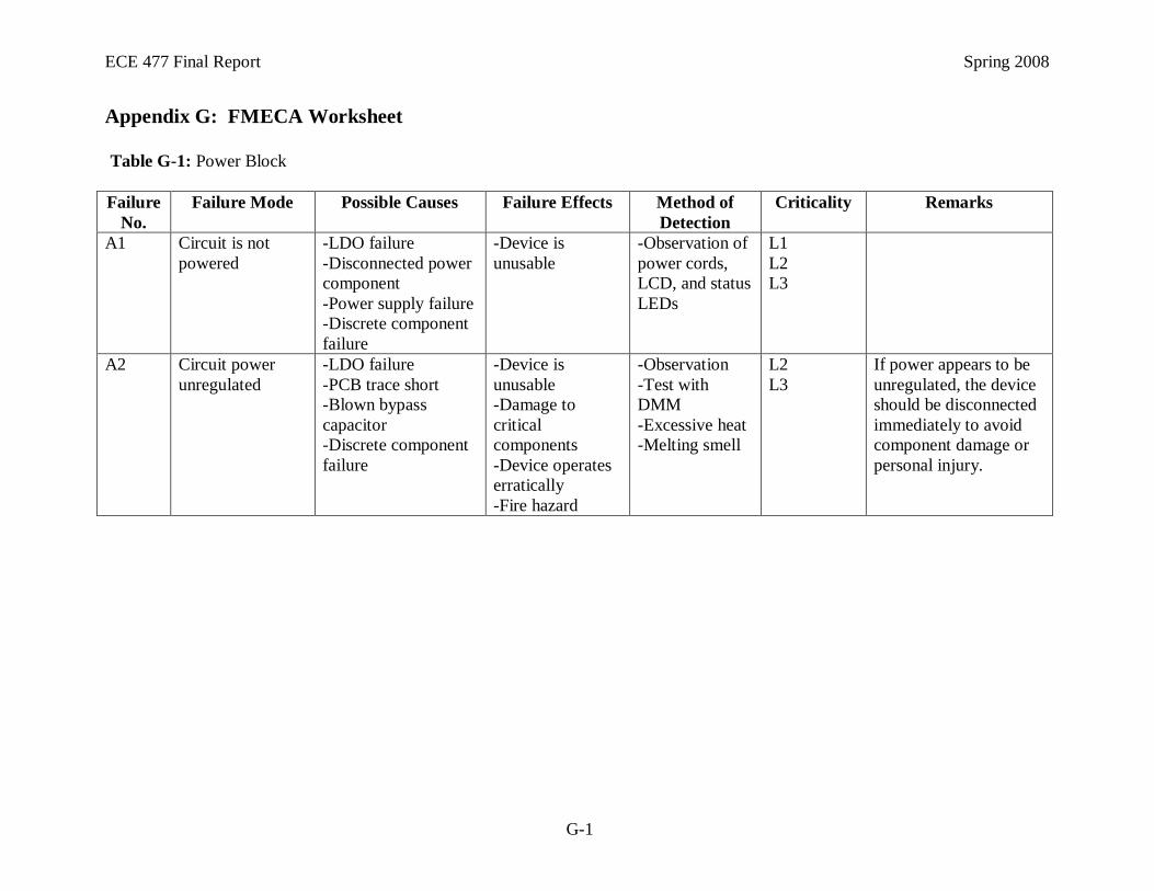
ECE 477 Final Report Spring 2008
G-1
Appendix G: FMECA Worksheet
Table G-1: Power Block
Failure
No.
Failure Mode Possible Causes Failure Effects Method of
Detection
Criticality Remarks
A1 Circuit is not
powered
-LDO failure
-Disconnected power
component
-Power supply failure
-Discrete component
failure
-Device is
unusable
-Observation of
power cords,
LCD, and status
LEDs
L1
L2
L3
A2 Circuit power
unregulated
-LDO failure
-PCB trace short
-Blown bypass
capacitor
-Discrete component
failure
-Device is
unusable
-Damage to
critical
components
-Device operates
erratically
-Fire hazard
-Observation
-Test with
DMM
-Excessive heat
-Melting smell
L2
L3
If power appears to be
unregulated, the device
should be disconnected
immediately to avoid
component damage or
personal injury.

ECE 477 Final Report Spring 2008
G-2
Table G-2: Microcontroller Block
Failure
No.
Failure Mode Possible Causes Failure Effects Method of
Detection
Criticality Remarks
B1 Device exhibits
little or no
functionality
-Shock
-Unregulated power
-Physical damage
-Memory damage
-Device operates
erratically
-Device is
unusable
-Observation of
unit
-Observation of
peripheral
performance
-Observation of
status LEDs
L2 T he device is unlikely
to operate in any
capacity in this failure
mode. Immediately
disconnect and service.
B2 Device cannot
communicate
with SD card
-SPI unit damaged
-SD card damage
-SD card reader is
disconnected
-Device cannot
read or update
user database
-Device cannot
load images to
display
-Software
detection
-Testing SD
card in different
device
L2 Device may still operate
in some capacity.
B3 Device cannot
communicate
with LCD
-LCD controller is
damaged
-LCD backlight is
dead
-SCI unit damaged
-Level shifter
damaged
-Cable disconnect
-Power disconnect
-Device cannot
update or display
images on LCD
-Observation
-Testing
components
with DMM
L1
L2
B4 Device cannot
communicate via
Ethernet
-Cable disconnect
-Unregulated power
-Ethernet unit
damaged
-Device cannot
update user
database or
images via
Ethernet
-Ping test L1
L2
Device may still
operate, but data will be
old.

ECE 477 Final Report Spring 2008
G-3
Table G-3: Serial Communication Block
Failure
No.
Failure Mode Possible Causes Failure Effects Method of
Detection
Criticality Remarks
C1 No
communication
with peripheral
devices
-Physical damage
-Disconnected cable
-Level shifter
malfunction
-Peripheral device is
damaged
-No
communication
with peripheral
-Device may be
unusable
-Observation of
unit
-Observation of
peripheral
behavior
L1
L2
Failure could result
from a large number of
peripheral-specific
causes.
C2 Garbled or
incorrect data
from peripheral
device
-Physical damage
-Peripheral device is
damaged
-Peripheral data rate
incorrect
-Sends or receives
incorrect or
garbled data
-No
communication
with peripheral
-Device may be
unusable
-Observation of
unit
-Observation of
peripheral
behavior
L1
L2
Failure could result
from a large number of
peripheral-specific
causes.
Table G-4: General Header Block
Failure
No.
Failure Mode Possible Causes Failure Effects Method of
Detection
Criticality Remarks
D1 Device does not
respond to push
button input
-Physical damage
-Disconnected cable
-Opt isolator
damaged
-Microcontroller pin
damaged
-Unit cannot enter
map display mode
-Observation of
unit
L1