ee-246 machiness_2012
TRANSCRIPT
PRACTICAL WORK BOOKFor Academic Session 2012
Electrical Machines (EE-246)For
S.E (TC) , S.E (CIS) & S .E (EL )
Name:Roll Number:Class:Batch: Semester/Term :Department :
Department of Electrical EngineeringNED University of Engineering & Technology

SAFETY RULES
1. Please don t touch any live parts. 2. Please don t work bare footed. 3. Never use an electrical tool near water. 4. Never use an electrical tool that has fallen into water. 5. Don t carry unnecessary item with you during performance (like water bottle,
bags etc) 6. Before connecting any leads/wires make sure power is switch off. 7. In case of emergency, push the nearby red color emergency switch of any panel
or immediately call the laboratory staff. 8. In case of electricity fire, never put water on it as it will further worse the
condition; use the class C fire extinguisher.
Fire is a chemical reaction involving rapid oxidation (combustion) of fuel. Three basic conditions when met, fire takes place. These are fuel, oxygen & heat, absence of any one of the component will extinguish the fire.
If there is a small electrical fire, be sure to use only a Class C or multipurpose (ABC) fire extinguisher, otherwise you might make the problem worsen.
The letters and symbols are explained in left figure. Easy to remember words are also shown.
Don t play with electricity, Treat electricity with respect, it deserves!
Figure: Fire Triangle
A(think ashes): paper, wood etc
B(think barrels): flammable liquids
C(think circuits): electrical fires
Electrical Machines Contents
NED University of Engineering and Technology Department of Electrical Engineering
Revised 2012MMA 2009 NA/AGA
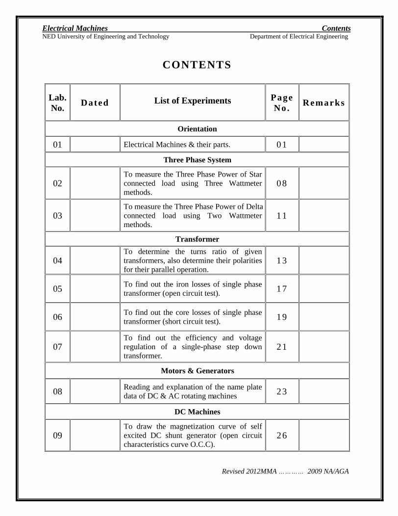
CONTENTS
Lab.
No.
Dated List of Experiments Page No .
Remarks
Orientation
01 Electrical Machines & their parts. 01
Three Phase System
02 To measure the Three Phase Power of Star connected load using Three Wattmeter methods.
08
03 To measure the Three Phase Power of Delta connected load using Two Wattmeter methods.
11
Transformer
04 To determine the turns ratio of given transformers, also determine their polarities for their parallel operation.
13
05 To find out the iron losses of single phase transformer (open circuit test). 17
06 To find out the core losses of single phase transformer (short circuit test). 19
07 To find out the efficiency and voltage regulation of a single-phase step down transformer.
21
Motors & Generators
08 Reading and explanation of the name plate data of DC & AC rotating machines 23
DC Machines
09 To draw the magnetization curve of self excited DC shunt generator (open circuit characteristics curve O.C.C).
26
Electrical Machines Contents
NED University of Engineering and Technology Department of Electrical Engineering
Revised 2012MMA 2009 NA/AGA
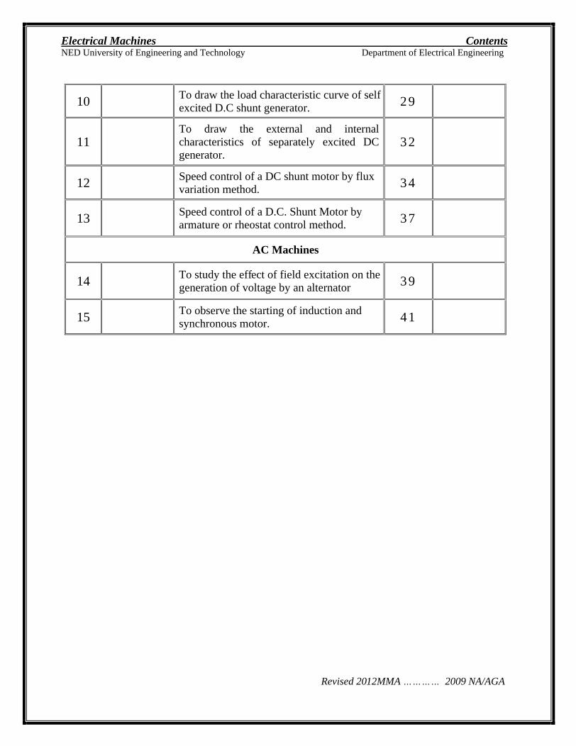
10 To draw the load characteristic curve of self excited D.C shunt generator. 29
11 To draw the external and internal characteristics of separately excited DC generator.
32
12 Speed control of a DC shunt motor by flux variation method. 34
13 Speed control of a D.C. Shunt Motor by armature or rheostat control method. 3 7
AC Machines
14 To study the effect of field excitation on the generation of voltage by an alternator 3 9
15 To observe the starting of induction and synchronous motor. 4 1
Electrical Machines Lab Session 01
NED University of Engineering and Technology Department of Electrical Engineering
- 1 - | P a g e
LAB SESSION 01
OBJECTIVE
To visualize the different Electrical Machines & identify their parts.
APPARATUS
Transformers
Fan Motor (Ceiling & Exhaust)
Washing Machine Motor
Pump Motor
Juicer Motor
Toys Motor
THEORY
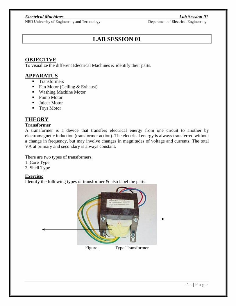
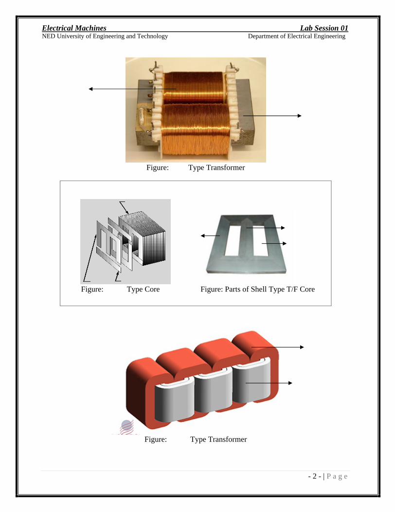
Transformer A transformer is a device that transfers electrical energy from one circuit to another by electromagnetic induction (transformer action). The electrical energy is always transferred without a change in frequency, but may involve changes in magnitudes of voltage and currents. The total VA at primary and secondary is always constant.
There are two types of transformers. 1. Core Type 2. Shell Type
Exercise:
Identify the following types of transformer & also label the parts.
Figure: Type Transformer
Electrical Machines Lab Session 01
NED University of Engineering and Technology Department of Electrical Engineering
- 2 - | P a g e
Figure: Type Transformer
Figure: Type Core Figure: Parts of Shell Type T/F Core
Figure: Type Transformer
Electrical Machines Lab Session 01
NED University of Engineering and Technology Department of Electrical Engineering
- 3 - | P a g e
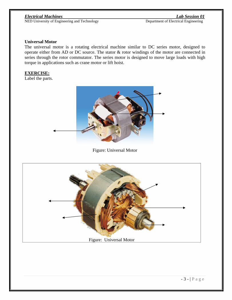
Universal Motor The universal motor is a rotating electrical machine similar to DC series motor, designed to operate either from AD or DC source. The stator & rotor windings of the motor are connected in series through the rotor commutator. The series motor is designed to move large loads with high torque in applications such as crane motor or lift hoist.
EXERCISE:
Label the parts.
Figure: Universal Motor
Figure: Universal Motor
Electrical Machines Lab Session 01
NED University of Engineering and Technology Department of Electrical Engineering
- 4 - | P a g e
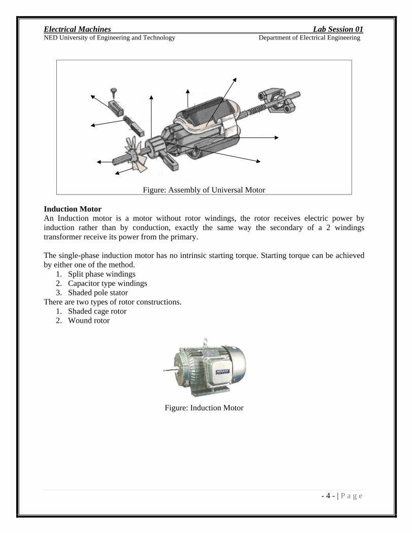
Figure: Assembly of Universal Motor
Induction Motor An Induction motor is a motor without rotor windings, the rotor receives electric power by induction rather than by conduction, exactly the same way the secondary of a 2 windings transformer receive its power from the primary.
The single-phase induction motor has no intrinsic starting torque. Starting torque can be achieved by either one of the method.
1. Split phase windings 2. Capacitor type windings 3. Shaded pole stator
There are two types of rotor constructions. 1. Shaded cage rotor 2. Wound rotor
Figure: Induction Motor
Electrical Machines Lab Session 01
NED University of Engineering and Technology Department of Electrical Engineering
- 5 - | P a g e
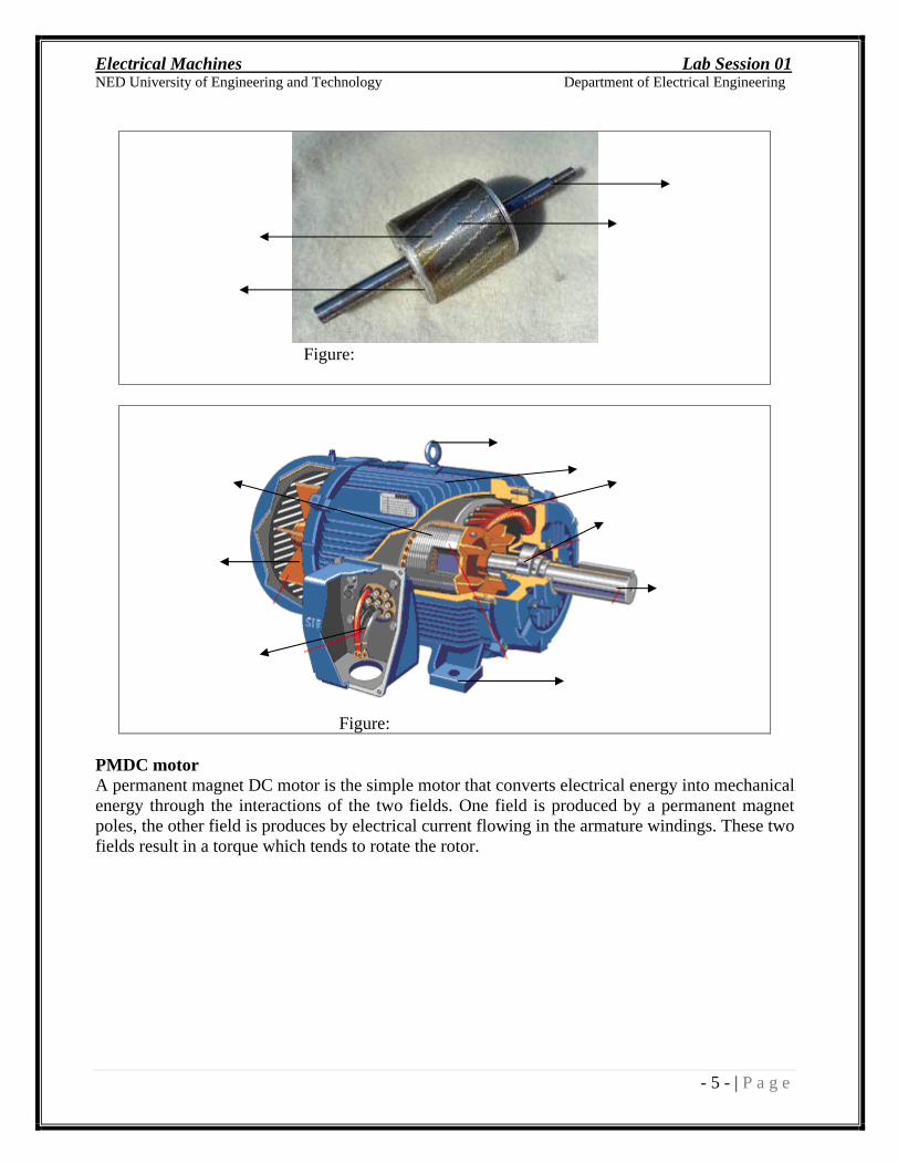
Figure:
Figure:
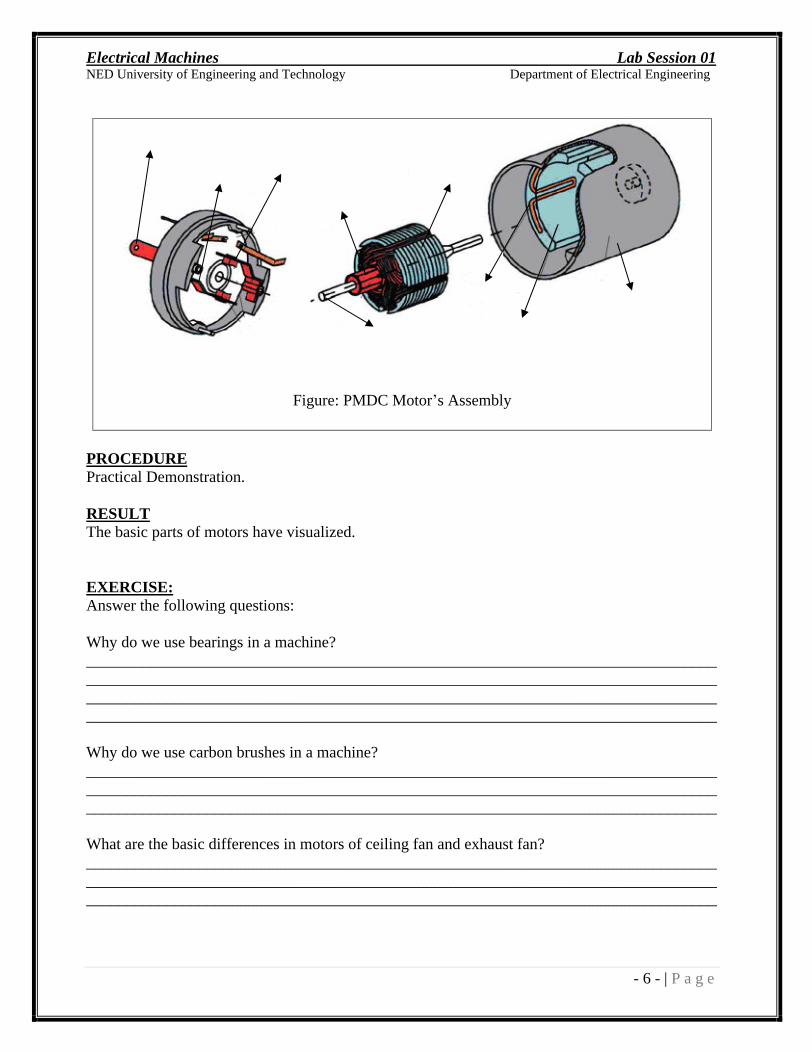
PMDC motor A permanent magnet DC motor is the simple motor that converts electrical energy into mechanical energy through the interactions of the two fields. One field is produced by a permanent magnet poles, the other field is produces by electrical current flowing in the armature windings. These two fields result in a torque which tends to rotate the rotor.
Electrical Machines Lab Session 01
NED University of Engineering and Technology Department of Electrical Engineering
- 6 - | P a g e
Figure: PMDC Motor s Assembly
PROCEDURE
Practical Demonstration.
RESULT
The basic parts of motors have visualized.
EXERCISE:
Answer the following questions:
Why do we use bearings in a machine? ____________________________________________________________________________________________________________________________________________________________________________________________________________________________________________________________________________________________________________________________
Why do we use carbon brushes in a machine? _____________________________________________________________________________________________________________________________________________________________________________________________________________________________________________
What are the basic differences in motors of ceiling fan and exhaust fan? _____________________________________________________________________________________________________________________________________________________________________________________________________________________________________________
Electrical Machines Lab Session 01
NED University of Engineering and Technology Department of Electrical Engineering
- 7 - | P a g e
Why do we use split rings and slip rings in a machine? ____________________________________________________________________________________________________________________________________________________________________________________________________________________________________________________________________________________________________________________________
When do we use Split rings and slip rings? ____________________________________________________________________________________________________________________________________________________________________________________________________________________________________________________________________________________________________________________________
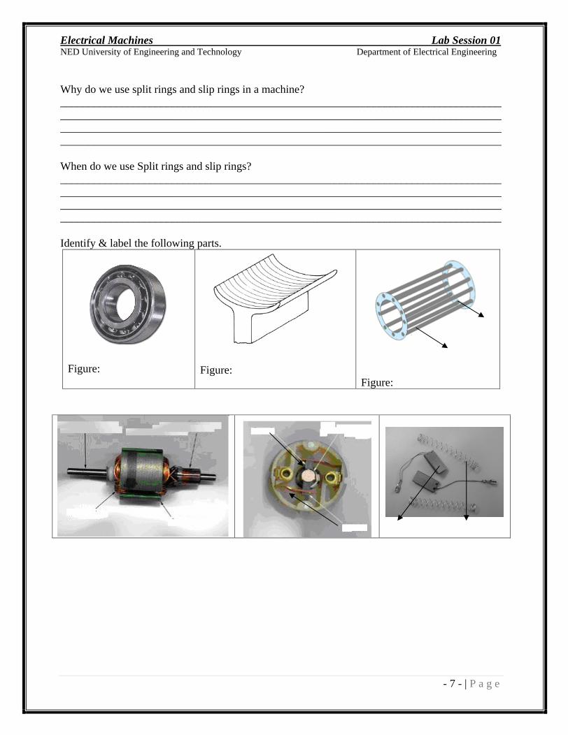
Identify & label the following parts.
Figure:
Figure:
Figure:
Electrical Machines Lab Session 02
NED University of Engineering and Technology Department of Electrical Engineering
- 8 - | P a g e
LAB SESSION 02
OBJECTIVE
To measure the Three Phase Power of Star connected load using Three Wattmeter methods.
APPARATUS
Three Watt-meters
Ammeter
Voltmeter
Star Connected Load
THEORY
Power can be measured with the help of 1. Ammeter and voltmeter (In DC circuits) 2. Wattmeter 3. Energy meter
By Ammeter and Voltmeter: Power in DC circuits or pure resistive circuit can be measured by measuring the voltage & current, then applying the formula P=VI.
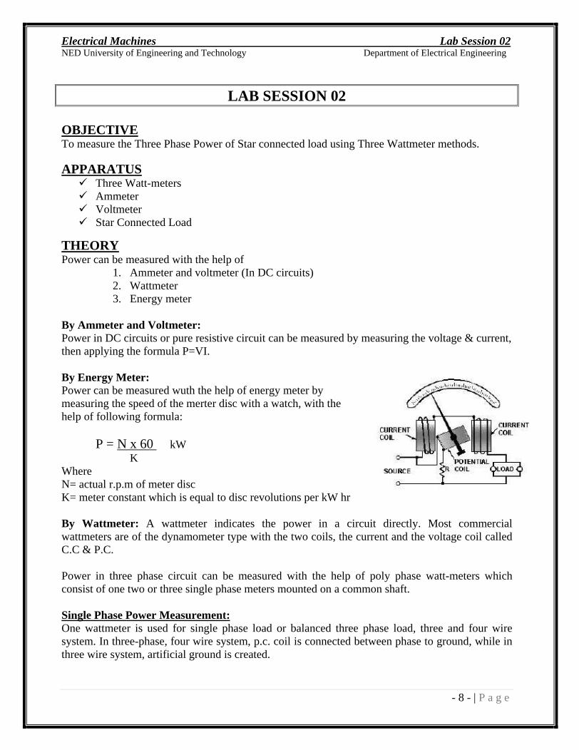
By Energy Meter: Power can be measured wuth the help of energy meter by measuring the speed of the merter disc with a watch, with the help of following formula:
P = N x 60 kW K
Where N= actual r.p.m of meter disc K= meter constant which is equal to disc revolutions per kW hr
By Wattmeter: A wattmeter indicates the power in a circuit directly. Most commercial wattmeters are of the dynamometer type with the two coils, the current and the voltage coil called C.C & P.C.
Power in three phase circuit can be measured with the help of poly phase watt-meters which consist of one two or three single phase meters mounted on a common shaft.
Single Phase Power Measurement:
One wattmeter is used for single phase load or balanced three phase load, three and four wire system. In three-phase, four wire system, p.c. coil is connected between phase to ground, while in three wire system, artificial ground is created.
Electrical Machines Lab Session 02
NED University of Engineering and Technology Department of Electrical Engineering
- 9 - | P a g e
Figure: Single Wattmeter Method
PROCEDURE
Arrange the watt-meters as shown above.
OBSERVATION
Phase Voltage: _______
S. No.
Size of Load Bank (By Observation)
Measured Load (Using Wattmeter)
Current (A)
Voltage (V)
1 05x100W 2 10x100W
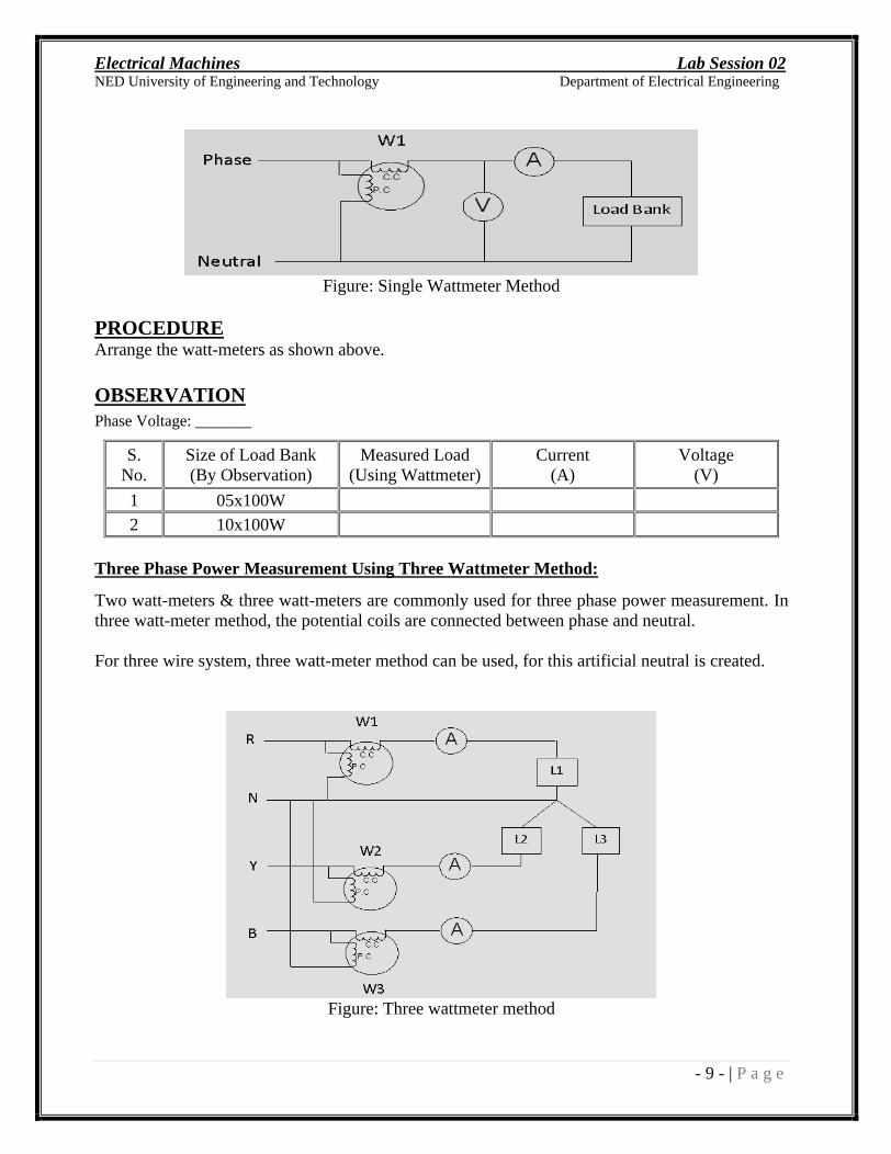
Three Phase Power Measurement Using Three Wattmeter Method:
Two watt-meters & three watt-meters are commonly used for three phase power measurement. In three watt-meter method, the potential coils are connected between phase and neutral.
For three wire system, three watt-meter method can be used, for this artificial neutral is created.
Figure: Three wattmeter method
Electrical Machines Lab Session 02
NED University of Engineering and Technology Department of Electrical Engineering
- 10 - | P a g e
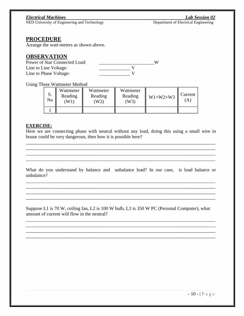
PROCEDURE
Arrange the watt-meters as shown above.
OBSERVATION
Power of Star Connected Load: _______________________W Line to Line Voltage: V Line to Phase Voltage: V
Using Three Wattmeter Method
S. No
Wattmeter Reading
(W1)
Wattmeter Reading
(W2)
Wattmeter Reading
(W3) W1+W2+W3
Current (A)
1
EXERCISE:
Here we are connecting phase with neutral without any load, doing this using a small wire in house could be very dangerous, then how it is possible here? ____________________________________________________________________________________________________________________________________________________________________________________________________________________________________________________________________________________________________________________________
What do you understand by balance and unbalance load? In our case, is load balance or unbalance? ____________________________________________________________________________________________________________________________________________________________________________________________________________________________________________________________________________________________________________________________
Suppose L1 is 70 W, ceiling fan, L2 is 100 W bulb, L3 is 350 W PC (Personal Computer), what amount of current will flow in the neutral? ____________________________________________________________________________________________________________________________________________________________________________________________________________________________________________________________________________________________________________________________
Electrical Machines Lab Session 03
NED University of Engineering and Technology Department of Electrical Engineering
- 11 - | P a g e
LAB SESSION 03
OBJECTIVE
To measure the Three Phase Power of Delta connected load using Two Wattmeter methods.
APPARATUS
Three Watt-meters
Ammeter
Voltmeter
Star Connected Load
THEORY
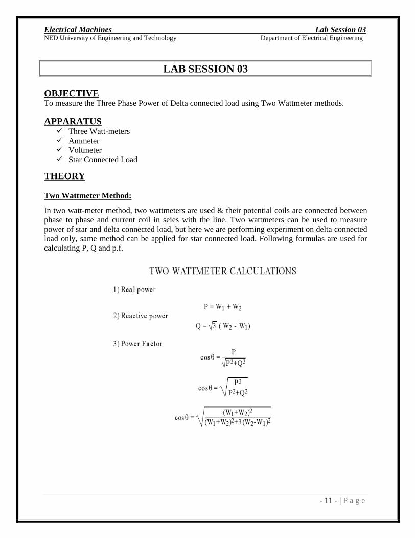
Two Wattmeter Method:
In two watt-meter method, two wattmeters are used & their potential coils are connected between phase to phase and current coil in seies with the line. Two wattmeters can be used to measure power of star and delta connected load, but here we are performing experiment on delta connected load only, same method can be applied for star connected load. Following formulas are used for calculating P, Q and p.f.
Electrical Machines Lab Session 03
NED University of Engineering and Technology Department of Electrical Engineering
- 12 - | P a g e
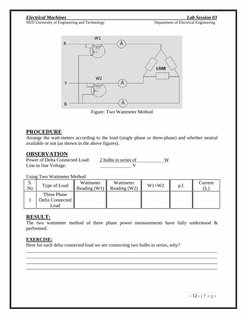
Figure: Two Wattmeter Method
PROCEDURE
Arrange the watt-meters according to the load (single phase or three-phase) and whether neutral available or not (as shown in the above figures).
OBSERVATION
Power of Delta Connected Load: 2 bulbs in series of W
Line to line Voltage: V
Using Two Wattmeter Method S. No
Type of Load Wattmeter
Reading (W1)
Wattmeter Reading (W2)
W1+W2 p.f. Current
(IL)
1 Three Phase
Delta Connected Load
RESULT:
The two wattmeter method of three phase power measurements have fully understood & performed.
EXERCISE:
Here for each delta connected load we are connecting two bulbs in series, why? ____________________________________________________________________________________________________________________________________________________________________________________________________________________________________________________________________________________________________________________________
Electrical Machines Lab Session 04
NED University of Engineering and Technology Department of Electrical Engineering
- 13 - | P a g e
LAB SESSION 04
OBJECTIVE
To determine the turns ratio of a transformer, also determine the polarity of transformer windings for their parallel operation.
APPARATUS
Two Single Phase Transformers (T1 & T2)
Ammeter
Voltmeter
THEORY
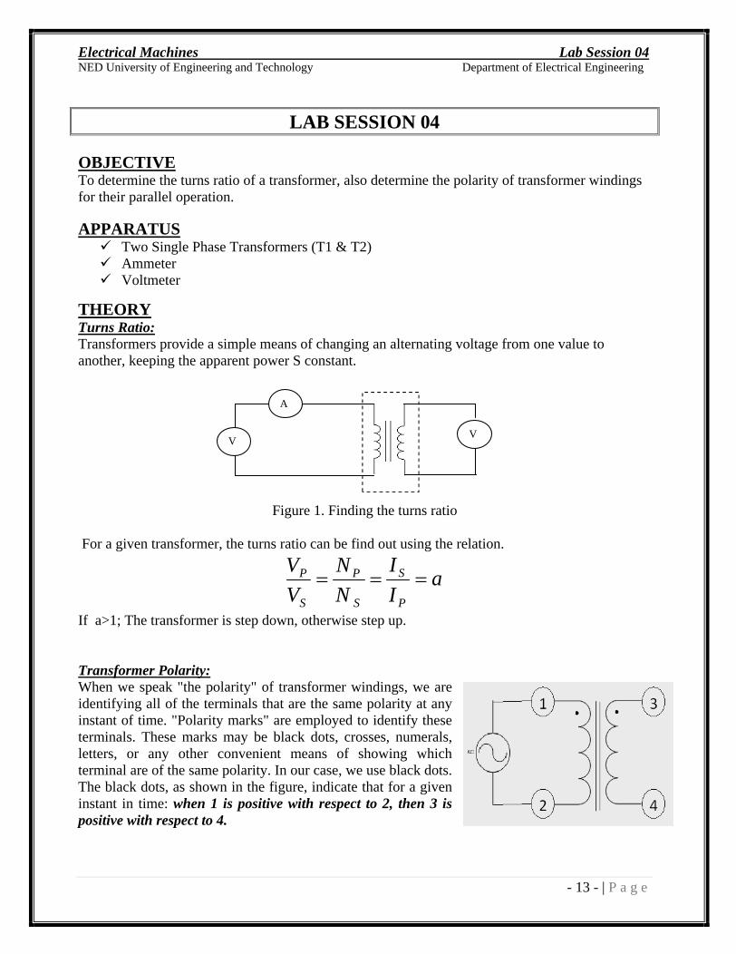
Turns Ratio:
Transformers provide a simple means of changing an alternating voltage from one value to another, keeping the apparent power S constant.
Figure 1. Finding the turns ratio
For a given transformer, the turns ratio can be find out using the relation.
aI
I
N
N
V
V
P
S
S
P
S
P
If a>1; The transformer is step down, otherwise step up.
Transformer Polarity:
When we speak "the polarity" of transformer windings, we are identifying all of the terminals that are the same polarity at any instant of time. "Polarity marks" are employed to identify these terminals. These marks may be black dots, crosses, numerals, letters, or any other convenient means of showing which terminal are of the same polarity. In our case, we use black dots. The black dots, as shown in the figure, indicate that for a given instant in time: when 1 is positive with respect to 2, then 3 is positive with respect to 4.
VsV
p
AM

Electrical Machines Lab Session 04
NED University of Engineering and Technology Department of Electrical Engineering
- 14 - | P a g e
The identification of polarity becomes essential when we operate the two transformers in parallel. Otherwise if terminals of unlike polarity connected to the same line, the two secondary windings would be short circuited on each other with a resulting excessive current flow.
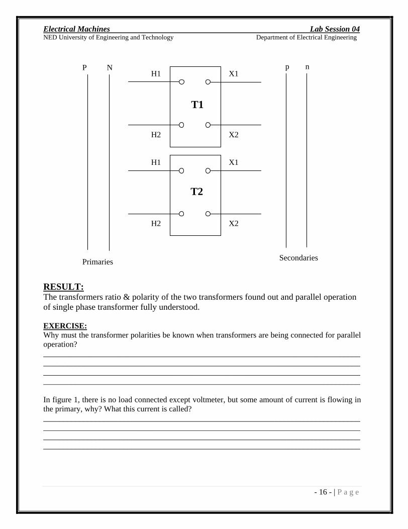
Suppose we have two transformers T1 & T2, having terminals H1, H2 (HV) & X1, X2(LV) as shown in figure 2. The transformers in fig 2 are so marked that if the H1 s are connected to one primary line and the H2 s to the other primary line then the X1 s should be connected to the same secondary line and X2 s to the remaining secondary line.
Figure 2: Two transformers connected for parallel operation
If the transformer terminals are arranged as shown in fig 3a, the transformer is said to have additive polarity and if arranged as shown in fig 3b, the transformer is said to have subtractive polarity.
Figure 3: Standard polarity markings of transformers (a) additive polarity (b) subtractive polarity
Electrical Machines Lab Session 04
NED University of Engineering and Technology Department of Electrical Engineering
- 15 - | P a g e
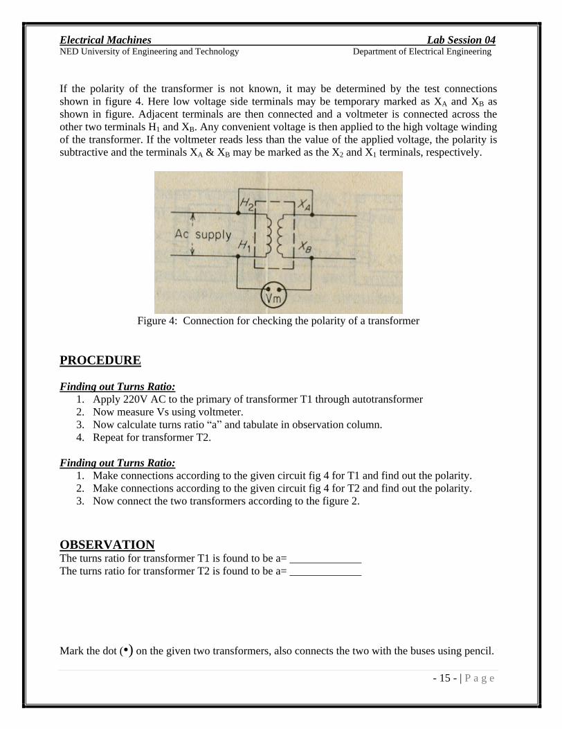
If the polarity of the transformer is not known, it may be determined by the test connections shown in figure 4. Here low voltage side terminals may be temporary marked as XA and XB as shown in figure. Adjacent terminals are then connected and a voltmeter is connected across the other two terminals H1 and XB. Any convenient voltage is then applied to the high voltage winding of the transformer. If the voltmeter reads less than the value of the applied voltage, the polarity is subtractive and the terminals XA & XB may be marked as the X2 and X1 terminals, respectively.
Figure 4: Connection for checking the polarity of a transformer
PROCEDURE
Finding out Turns Ratio:
1. Apply 220V AC to the primary of transformer T1 through autotransformer 2. Now measure Vs using voltmeter. 3. Now calculate turns ratio a and tabulate in observation column. 4. Repeat for transformer T2.
Finding out Turns Ratio:
1. Make connections according to the given circuit fig 4 for T1 and find out the polarity. 2. Make connections according to the given circuit fig 4 for T2 and find out the polarity. 3. Now connect the two transformers according to the figure 2.
OBSERVATION
The turns ratio for transformer T1 is found to be a= _____________ The turns ratio for transformer T2 is found to be a= _____________
Mark the dot ( ) on the given two transformers, also connects the two with the buses using pencil.
Electrical Machines Lab Session 04
NED University of Engineering and Technology Department of Electrical Engineering
- 16 - | P a g e
RESULT:
The transformers ratio & polarity of the two transformers found out and parallel operation of single phase transformer fully understood.
EXERCISE:
Why must the transformer polarities be known when transformers are being connected for parallel operation? ____________________________________________________________________________________________________________________________________________________________________________________________________________________________________________________________________________________________________________________________
In figure 1, there is no load connected except voltmeter, but some amount of current is flowing in the primary, why? What this current is called? ____________________________________________________________________________________________________________________________________________________________________________________________________________________________________________________________________________________________________________________________
H1
X1
X2
H2
H1
X1
X2
H2
T1
T2
P N p n
Primaries Secondaries
Electrical Machines Lab Session 05
NED University of Engineering and Technology Department of Electrical Engineering
- 17 - | P a g e
LAB SESSION 05
OBJECT
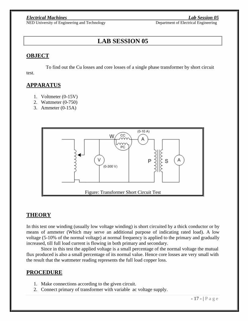
To find out the Cu losses and core losses of a single phase transformer by short circuit test.
APPARATUS
1. Voltmeter (0-15V) 2. Wattmeter (0-750) 3. Ammeter (0-15A)
Figure: Transformer Short Circuit Test
THEORY
In this test one winding (usually low voltage winding) is short circuited by a thick conductor or by means of ammeter (Which may serve an additional purpose of indicating rated load). A low voltage (5-10% of the normal voltage) at normal frequency is applied to the primary and gradually increased, till full load current is flowing in both primary and secondary.
Since in this test the applied voltage is a small percentage of the normal voltage the mutual flux produced is also a small percentage of its normal value. Hence core losses are very small with the result that the wattmeter reading represents the full load copper loss.
PROCEDURE
1. Make connections according to the given circuit. 2. Connect primary of transformer with variable ac voltage supply.
Electrical Machines Lab Session 05
NED University of Engineering and Technology Department of Electrical Engineering
- 18 - | P a g e
3. Note down transformer rated current from name plate data and keep on increasing voltage
until you get rated current read by Ammeter connected. 4. Once you get rated current at any specific voltage level, note down reading of instruments
connected and calculate different parameters.
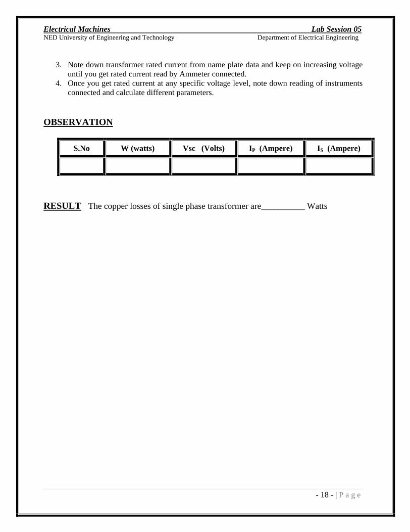
OBSERVATION
S.No W (watts) Vsc (Volts) IP (Ampere) IS (Ampere)
RESULT The copper losses of single phase transformer are__________ Watts
Electrical Machines Lab Session 06
NED University of Engineering and Technology Department of Electrical Engineering
- 19 - | P a g e
LAB SESSION 06
OBJECT
To find out the iron losses of single phase transformer (open circuit test).
APPRATUS
1. Voltmeter (0 300V )
2. Ammeter ( 0 2A ) 3. Wattmeter ( 0 120 W )
CIRCUIT DIAGRAM
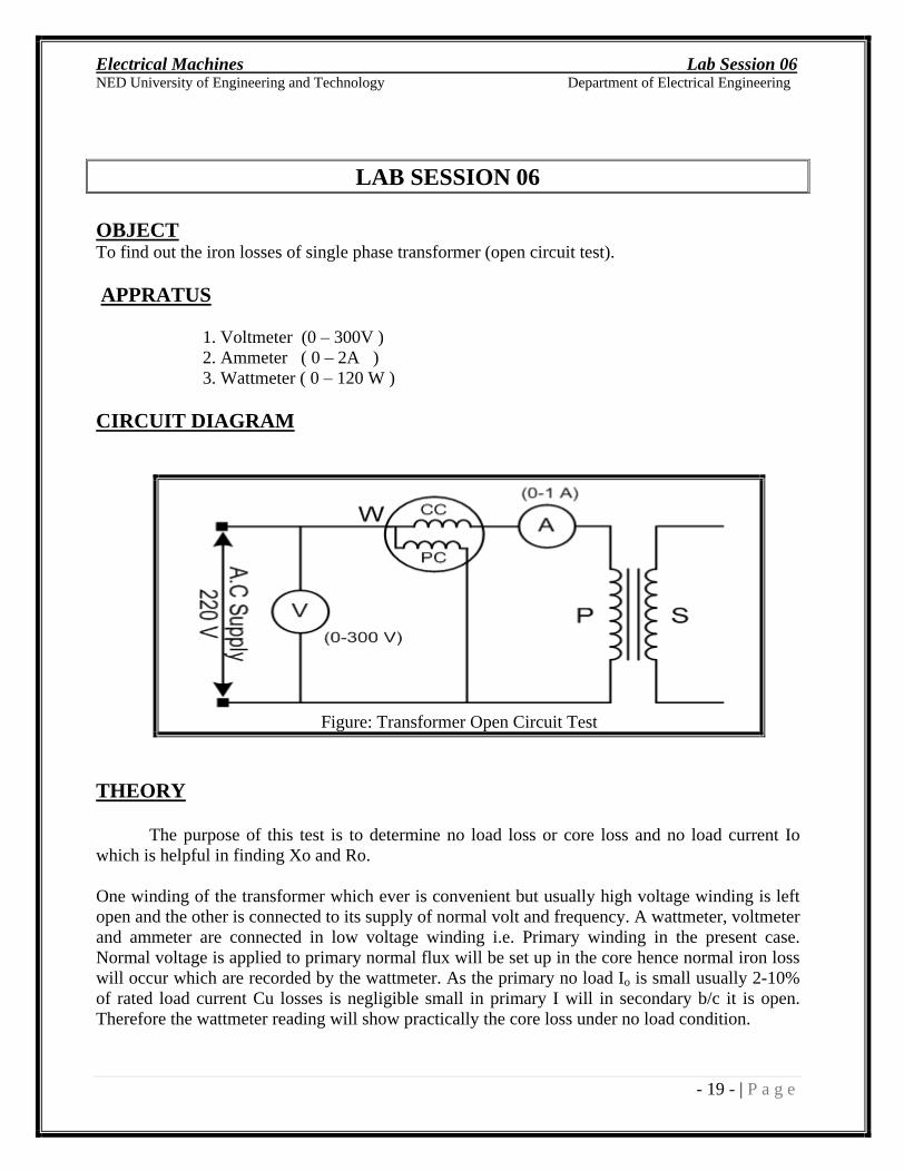
Figure: Transformer Open Circuit Test
THEORY
The purpose of this test is to determine no load loss or core loss and no load current Io which is helpful in finding Xo and Ro. One winding of the transformer which ever is convenient but usually high voltage winding is left open and the other is connected to its supply of normal volt and frequency. A wattmeter, voltmeter and ammeter are connected in low voltage winding i.e. Primary winding in the present case. Normal voltage is applied to primary normal flux will be set up in the core hence normal iron loss will occur which are recorded by the wattmeter. As the primary no load Io is small usually 2-10% of rated load current Cu losses is negligible small in primary I will in secondary b/c it is open. Therefore the wattmeter reading will show practically the core loss under no load condition.
Electrical Machines Lab Session 06
NED University of Engineering and Technology Department of Electrical Engineering
- 20 - | P a g e
OBSERVATIONS
S.No W (watts) V (Volts) Io (Ampere)
RESULT
The iron losses of single phase transformer are ___________ watt.
EXERCISE:
Answer the following questions:
Why do we perform short circuit & open circuit test on a transformer? What information we get? ____________________________________________________________________________________________________________________________________________________________________________________________________________________________________________________________________________________________________________________________
Why do we apply rated voltage in open circuit test and below rated voltage in short circuit test? ____________________________________________________________________________________________________________________________________________________________________________________________________________________________________________________________________________________________________________________________ _______________________________________________________________________________
Calculate the value of Xm, Rc, Req,p & Xeq,p from the observations table of Exp 5 & 6. CALCULATIONS:
Electrical Machines Lab Session 07
NED University of Engineering and Technology Department of Electrical Engineering
- 21 - | P a g e
LAB SESSION 07
OBJECT
To find out the efficiency and voltage regulation of a single-phase step down transformer.
APPARATUS
1. Two Voltmeters (0 300V), (0 150V) 2. Two Ammeters (0 1A) 3. Step- down transformer 4. Variable load
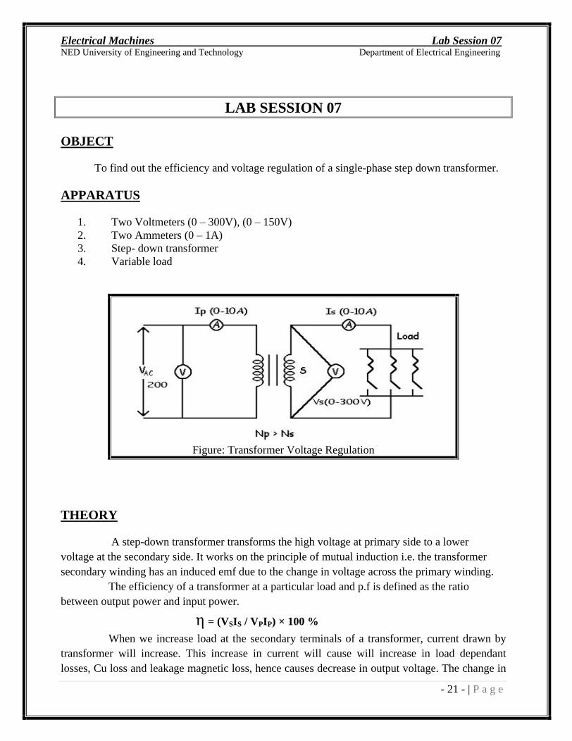
Figure: Transformer Voltage Regulation
THEORY
A step-down transformer transforms the high voltage at primary side to a lower voltage at the secondary side. It works on the principle of mutual induction i.e. the transformer secondary winding has an induced emf due to the change in voltage across the primary winding. The efficiency of a transformer at a particular load and p.f is defined as the ratio between output power and input power.
= (VSIS / VPIP) × 100 %
When we increase load at the secondary terminals of a transformer, current drawn by transformer will increase. This increase in current will cause will increase in load dependant losses, Cu loss and leakage magnetic loss, hence causes decrease in output voltage. The change in
Electrical Machines Lab Session 07
NED University of Engineering and Technology Department of Electrical Engineering
- 22 - | P a g e
secondary voltage from no load to full load with respect to no load voltage or with respect to full load voltage is called voltage regulation.
(Voltage Regulation) VR = [(VSN VSL) / V SN] × 100 %
PROCEDURE
1. Make the connections as shown in figure. 2. Switch on primary supply and read the no load secondary voltage. 3. Increase the load on the secondary side in steps 4. Following every step take reading.
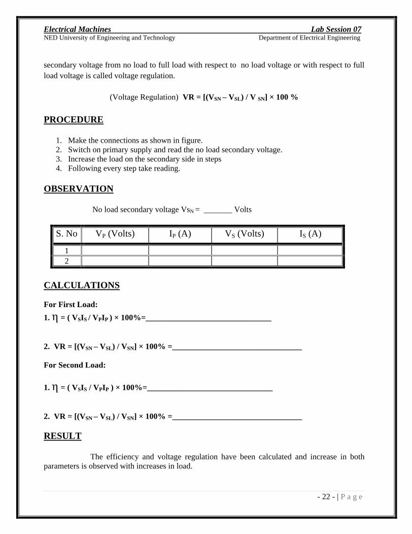
OBSERVATION
No load secondary voltage VsN = _______ Volts
S. No
VP (Volts) IP (A) VS (Volts) IS (A)
1 2
CALCULATIONS
For First Load:
1.
= ( VSIS / VPIP ) × 100%=_______________________________
2. VR = [(VSN VSL) / VSN] × 100% =________________________________ For Second Load:
1.
= ( VSIS / VPIP ) × 100%=_______________________________
2. VR = [(VSN VSL) / VSN] × 100% =________________________________
RESULT
The efficiency and voltage regulation have been calculated and increase in both parameters is observed with increases in load.
Electrical Machines Lab Session 08
NED University of Engineering and Technology Department of Electrical Engineering
- 23 - | P a g e
LAB SESSION 08
OBJECT
Reading and explanation of the name plate data of DC & AC rotating machines.
APPARATUS
1. DC Motor 2. DC Generator 3. 3- Induction Motor 4. 3- Synchronous Motor 5. 3- Synchronous Generator
THEORY
Name plate, is a sheet fixed on every electrical machine, shows the rated parameters. Rated parameters are the parameters on which machine perform at best efficiency. Therefore it is of immense importance to know about the rated parameters of any machines before putting it in operation. In addition to this, these parameters are also necessary for the further analysis like designing any controlling circuitry for that machine. Name plate data includes voltage, current, ambient temperature, number of poles, operating frequency, enclosure type, cooling employed, field current and voltage (in case of doubly excited machines/generator) etc.
PROCEDURE
Check out name plate data of machines on different benches given below, installed at different benches.
1.
NAME PLATE DATA OF DC MOTOR (Bench - ):
1 6
2 7
3 8
4 9
5 10

Electrical Machines Lab Session 08
NED University of Engineering and Technology Department of Electrical Engineering
- 24 - | P a g e
2.
NAME PLATE DATA OF DC GENERATOR (Bench - ):
1 6
2 7
3 8
4 9
5 10
3.
NAME PLATE DATA OF 3- INDUCTION MOTOR (Bench - ):
1 6
2 7
3 8
4 9
5 10
4.
NAME PLATE DATA OF 3- SYNCHRONOUS MOTOR (Bench - ):
1 6
2 7
3 8
4 9
5 10
5.
NAME PLATE DATA OF 3- SYNCHRONOUS GENERATOR (Bench - ):
1 6
2 7
3 8
4 9
5 10
Electrical Machines Lab Session 08
NED University of Engineering and Technology Department of Electrical Engineering
- 25 - | P a g e
EXERCISE:
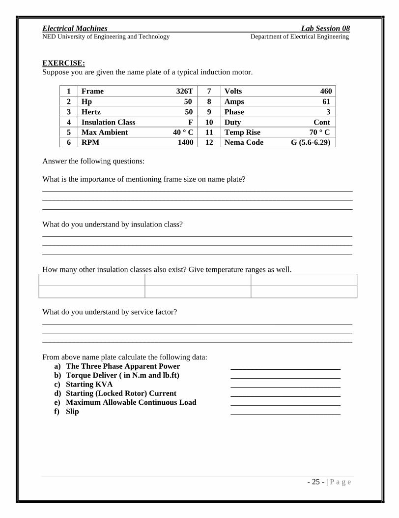
Suppose you are given the name plate of a typical induction motor.
1 Frame 326T 7 Volts 460
2 Hp 50 8 Amps 61 3 Hertz 50 9 Phase 3 4 Insulation Class F 10 Duty Cont 5 Max Ambient 40 ° C
11 Temp Rise 70 ° C 6 RPM 1400
12 Nema Code G (5.6-6.29)
Answer the following questions:
What is the importance of mentioning frame size on name plate? _____________________________________________________________________________________________________________________________________________________________________________________________________________________________________________
What do you understand by insulation class? _____________________________________________________________________________________________________________________________________________________________________________________________________________________________________________
How many other insulation classes also exist? Give temperature ranges as well.
What do you understand by service factor? _____________________________________________________________________________________________________________________________________________________________________________________________________________________________________________
From above name plate calculate the following data: a) The Three Phase Apparent Power ____________________________ b) Torque Deliver ( in N.m and lb.ft) ____________________________ c) Starting KVA ____________________________ d) Starting (Locked Rotor) Current ____________________________ e) Maximum Allowable Continuous Load ____________________________ f) Slip ____________________________
Electrical Machines Lab Session 09
NED University of Engineering and Technology Department of Electrical Engineering
- 26 - | P a g e
LAB SESSION 09
OBJECT
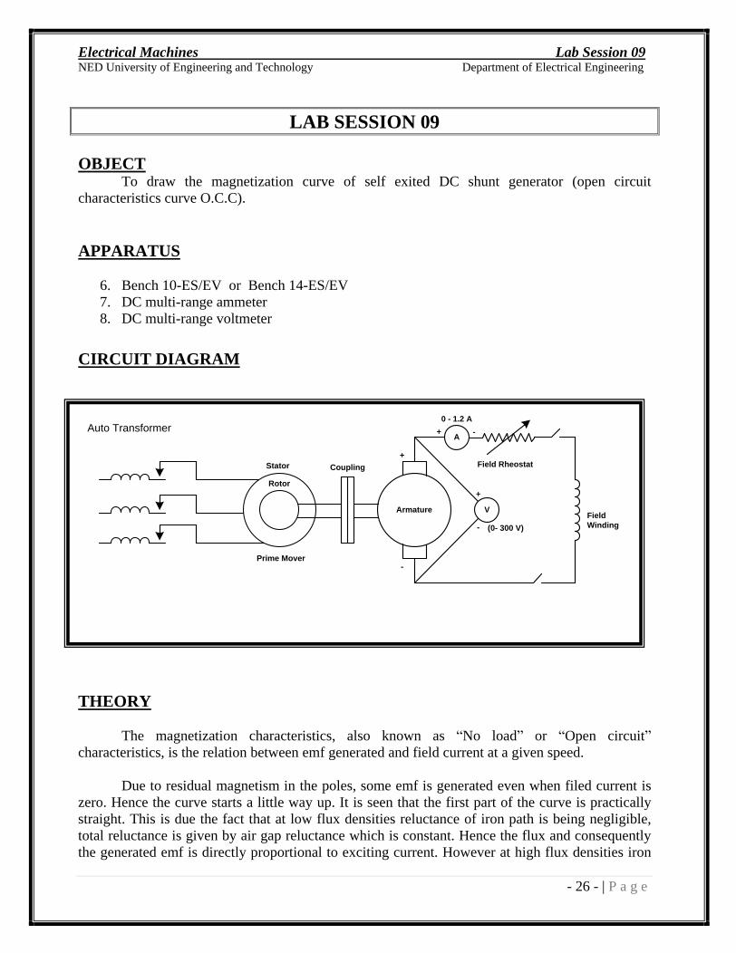
To draw the magnetization curve of self exited DC shunt generator (open circuit
characteristics curve O.C.C).
APPARATUS
6. Bench 10-ES/EV or Bench 14-ES/EV 7. DC multi-range ammeter 8. DC multi-range voltmeter
CIRCUIT DIAGRAM
THEORY
The magnetization characteristics, also known as No load or Open circuit characteristics, is the relation between emf generated and field current at a given speed.
Due to residual magnetism in the poles, some emf is generated even when filed current is zero. Hence the curve starts a little way up. It is seen that the first part of the curve is practically straight. This is due the fact that at low flux densities reluctance of iron path is being negligible, total reluctance is given by air gap reluctance which is constant. Hence the flux and consequently the generated emf is directly proportional to exciting current. However at high flux densities iron
Rotor
Stator
Armature V
A
Prime Mover
Auto Transformer
FieldWinding
0 - 1.2 A
+
-
Coupling
+
+
-
-
Field Rheostat
(0- 300 V)
Electrical Machines Lab Session 09
NED University of Engineering and Technology Department of Electrical Engineering
- 27 - | P a g e
path reluctance is being appreciable and straight relation between emf and field current no longer holds good. In other words saturation of poles starts.
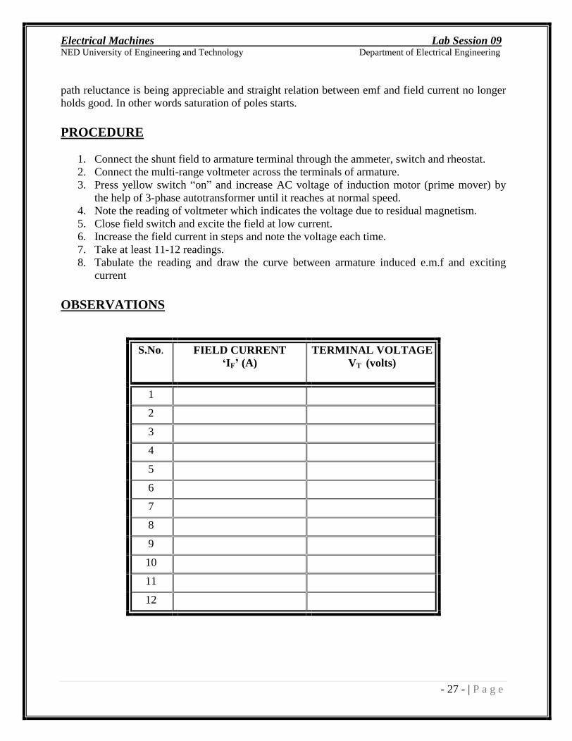
PROCEDURE
1. Connect the shunt field to armature terminal through the ammeter, switch and rheostat. 2. Connect the multi-range voltmeter across the terminals of armature. 3. Press yellow switch on and increase AC voltage of induction motor (prime mover) by
the help of 3-phase autotransformer until it reaches at normal speed. 4. Note the reading of voltmeter which indicates the voltage due to residual magnetism. 5. Close field switch and excite the field at low current. 6. Increase the field current in steps and note the voltage each time. 7. Take at least 11-12 readings. 8. Tabulate the reading and draw the curve between armature induced e.m.f and exciting
current
OBSERVATIONS
S.No. FIELD CURRENT IF (A)
TERMINAL VOLTAGE
VT (volts)
1
2
3
4
5
6
7
8
9
10
11
12

Electrical Machines Lab Session 09
NED University of Engineering and Technology Department of Electrical Engineering
- 28 - | P a g e
RESULT
1. The curve starts somewhat above the origin. The voltage at zero excitation is due to
residual magnetism of the field, which is necessary for building up the voltage of self-excitation generator.
2. The voltage increases rapidly at first and then changes a little in value at higher excitations indicating the effect of the poles saturation.
EXERCISE:
Answer the following questions:
What do you understand by Self Excited ? If this is a self excited machine then why there is a need of supplying voltage to the auto transformer?
_______________________________________________________________________________
_______________________________________________________________________________
_______________________________________________________________________________
_______________________________________________________________________________
Electrical Machines Lab Session 10
NED University of Engineering and Technology Department of Electrical Engineering
- 29 - | P a g e
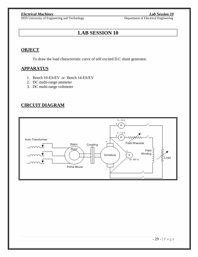
LAB SESSION 10
OBJECT
To draw the load characteristic curve of self excited D.C shunt generator.
APPARATUS
1. Bench 10-ES/EV or Bench 14-ES/EV 2. DC multi-range ammeter 3. DC multi-range voltmeter
CIRCUIT DIAGRAM
Electrical Machines Lab Session 10
NED University of Engineering and Technology Department of Electrical Engineering
- 30 - | P a g e
THEORY
Load characteristic curve is the graphical representation which shows change in terminal
voltage with respect to change in load. After building up of voltage, if a shunt generator is loaded then terminal voltage drops with increase in load current. There are three main reasons for the drop of terminal voltage for a shunt generator under load.
i) Armature Reaction
Armature reaction is the effect of magnetic field set up by the armature current on the distribution of flux under main poles of a generator. Due to demagnetizing effect of armature reaction , pole flux is weakened and so induced e.m.f in the armature is decresed.
ii) Armature Resistance
As the load current increases, more voltage is consumed in ohmic resistance of armature circuit. Hence the terminal voltage (Vt=E IaRa) is decreased where E is the e.m.f induced in armature under load condition.
iii) Drop In Terminal Voltage
The drop in terminal voltage (Vt) due to armature resistance and armature reaction results in decreased field current, which further reduces e.m.f induced.
For a shunt generator Ia = IL+ If
E = Vt + IaRa
PROCEDURE
1. Make the connections as shown in circuit diagram. 2. Press yellow switch on and increase AC voltage of induction motor (prime mover) by
the help of 3-phase autotransformer until it reaches at normal speed. 3. When motor reaches rated speed, close the shunt field switch. 4. Increase field current by changing the field resistance until the terminal voltage reaches to
220 volt. 5. Close the switch of load and vary the load current by means of load rheostat. 6. Note down the meter readings from all meters carefully.
Electrical Machines Lab Session 10
NED University of Engineering and Technology Department of Electrical Engineering
- 31 - | P a g e
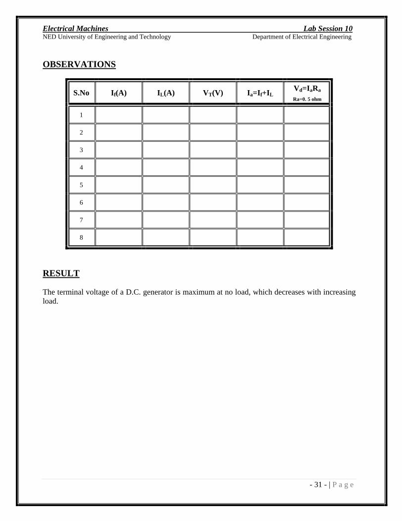
OBSERVATIONS
S.No If(A) IL(A) VT(V) Ia=If+IL
Vd=IaRa
Ra=0. 5 ohm
1
2
3
4
5
6
7
8
RESULT
The terminal voltage of a D.C. generator is maximum at no load, which decreases with increasing load.
Electrical Machines Lab Session 11
NED University of Engineering and Technology Department of Electrical Engineering
- 32 - | P a g e
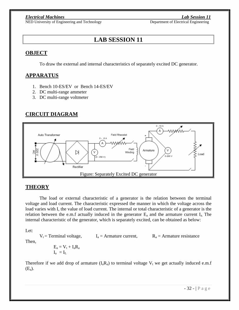
LAB SESSION 11
OBJECT
To draw the external and internal characteristics of separately excited DC generator.
APPARATUS
1. Bench 10-ES/EV or Bench 14-ES/EV 2. DC multi-range ammeter 3. DC multi-range voltmeter
CIRCUIT DIAGRAM
Figure: Separately Excited DC generator
THEORY
The load or external characteristic of a generator is the relation between the terminal voltage and load current. The characteristic expressed the manner in which the voltage across the load varies with I, the value of load current. The internal or total characteristic of a generator is the relation between the e.m.f actually induced in the generator Ea and the armature current Ia. The internal characteristic of the generator, which is separately excited, can be obtained as below:
Let: Vt = Terminal voltage, Ia = Armature current, Ra = Armature resistance
Then, Ea = Vt + IaRa
Ia = IL
Therefore if we add drop of armature (IaRa) to terminal voltage Vt we get actually induced e.m.f (Ea).
Electrical Machines Lab Session 11
NED University of Engineering and Technology Department of Electrical Engineering
- 33 - | P a g e
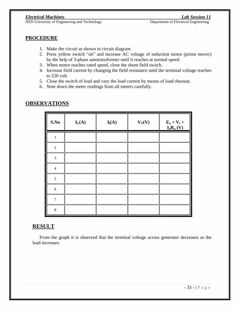
PROCEDURE
1. Make the circuit as shown in circuit diagram. 2. Press yellow switch on and increase AC voltage of induction motor (prime mover)
by the help of 3-phase autotransformer until it reaches at normal speed. 3. When motor reaches rated speed, close the shunt field switch. 4. Increase field current by changing the field resistance until the terminal voltage reaches
to 220 volt. 5. Close the switch of load and vary the load current by means of load rheostat. 6. Note down the meter readings from all meters carefully.
OBSERVATIONS
S.No IL(A) If(A) VT(V) Ea = Vt + IaRa (V)
1
2
3
4
5
6
7
8
RESULT
From the graph it is observed that the terminal voltage across generator decreases as the load increases.
Electrical Machines Lab Session 12
NED University of Engineering and Technology Department of Electrical Engineering
- 34 - | P a g e
LAB SESSION 12
OBJECT
Speed control of a DC shunt motor by flux variation method.
APPARATUS
1. Bench 13-ES/EV or Bench 15-ES/EV 2. DC multi-range ammeter 3. DC multi range voltmeters
4. Digital tachometer
CIRCUIT DIAGRAM
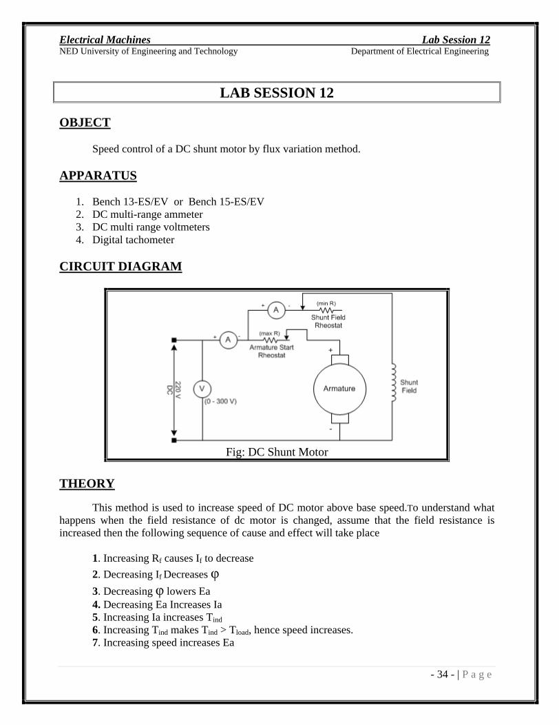
Fig: DC Shunt Motor
THEORY
This method is used to increase speed of DC motor above base speed.To understand what happens when the field resistance of dc motor is changed, assume that the field resistance is increased then the following sequence of cause and effect will take place
1. Increasing Rf causes If to decrease
2. Decreasing If Decreases
3. Decreasing lowers Ea 4. Decreasing Ea Increases Ia 5. Increasing Ia increases Tind
6. Increasing Tind makes Tind > Tload, hence speed increases. 7. Increasing speed increases Ea
Electrical Machines Lab Session 12
NED University of Engineering and Technology Department of Electrical Engineering
- 35 - | P a g e
8. Increasing Ea decreases Ia 9. Decreasing Ia decrease Tind until Tind = Tload at higher speed. Naturally decreasing Rf would reverse the whole process and speed of motor will decrease.
It is important to bear in mind, changing field resistance does not effect torque induced ,at the end its magnitude remains same but at higher or lower speed depending upon change in resistance.
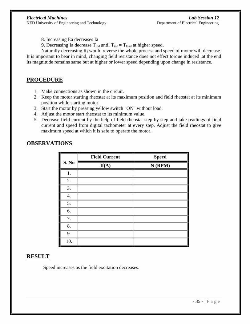
PROCEDURE
1. Make connections as shown in the circuit. 2. Keep the motor starting rheostat at its maximum position and field rheostat at its minimum
position while starting motor. 3. Start the motor by pressing yellow switch "ON" without load. 4. Adjust the motor start rheostat to its minimum value. 5. Decrease field current by the help of field rheostat step by step and take readings of field
current and speed from digital tachometer at every step. Adjust the field rheostat to give maximum speed at which it is safe to operate the motor.
OBSERVATIONS
Field Current Speed
S. No If(A) N (RPM)
1.
2.
3.
4.
5.
6.
7.
8.
9.
10.
RESULT
Speed increases as the field excitation decreases.

Electrical Machines Lab Session 12
NED University of Engineering and Technology Department of Electrical Engineering
- 36 - | P a g e
EXERCISE:
Answer the following questions:
Why do we set the armature rheostat at maximum and field rheostat at minimum? _______________________________________________________________________________
_______________________________________________________________________________
_______________________________________________________________________________
_______________________________________________________________________________
_______________________________________________________________________________
_______________________________________________________________________________
After starting motor, why do we set the Ra to its minimum?
______________________________________________________________________________________________
______________________________________________________________________________________________
______________________________________________________________________________
__________________________________________________________________________
Electrical Machines Lab Session 13
NED University of Engineering and Technology Department of Electrical Engineering
- 37 - | P a g e
LAB SESSION 13
OBJECT
Speed control of a D.C. Shunt Motor by armature rheostatic control method.
APPARATUS
1. Bench 13-ES/EV or Bench 15-ES/EV 2. DC multi-range ammeter 3. Voltmeters
4. Digital tachometer
CIRCUIT DIAGRAM
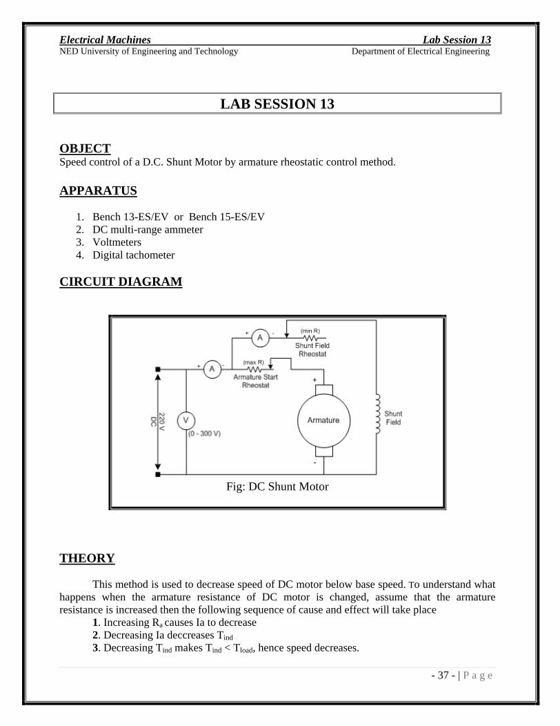
Fig: DC Shunt Motor
THEORY
This method is used to decrease speed of DC motor below base speed. To understand what happens when the armature resistance of DC motor is changed, assume that the armature resistance is increased then the following sequence of cause and effect will take place
1. Increasing Ra causes Ia to decrease 2. Decreasing Ia deccreases Tind
3. Decreasing Tind makes Tind < Tload, hence speed decreases.
Electrical Machines Lab Session 13
NED University of Engineering and Technology Department of Electrical Engineering
- 38 - | P a g e
4. Decreasing speed decreases Ea 5. Decreasing Ea increases Ia again. 6. Increasing Ia increases Tind until Tind = Tload at lower speed.
Naturally decreasing Ra would reverse the whole process and speed of motor will increase. It is important to bear in mind, changing armature resistance does not effect torque induced ,at the end its magnitude remains same but at higher or lower speed depending upon change in resistance.
PROCEDURE
1. Make connections as shown in the circuit. 2. Keep the motor starting rheostat at its maximum position and field rheostat at its minimum
position while starting motor. 3. Start the motor by pressing yellow switch "ON" without load. 4. Adjust the motor start rheostat to its minimum value. 5. Increase the value of starting resistance by the help of motor start rheostat step by step and
take readings of voltage across armature and speed from digital tachometer at every step.
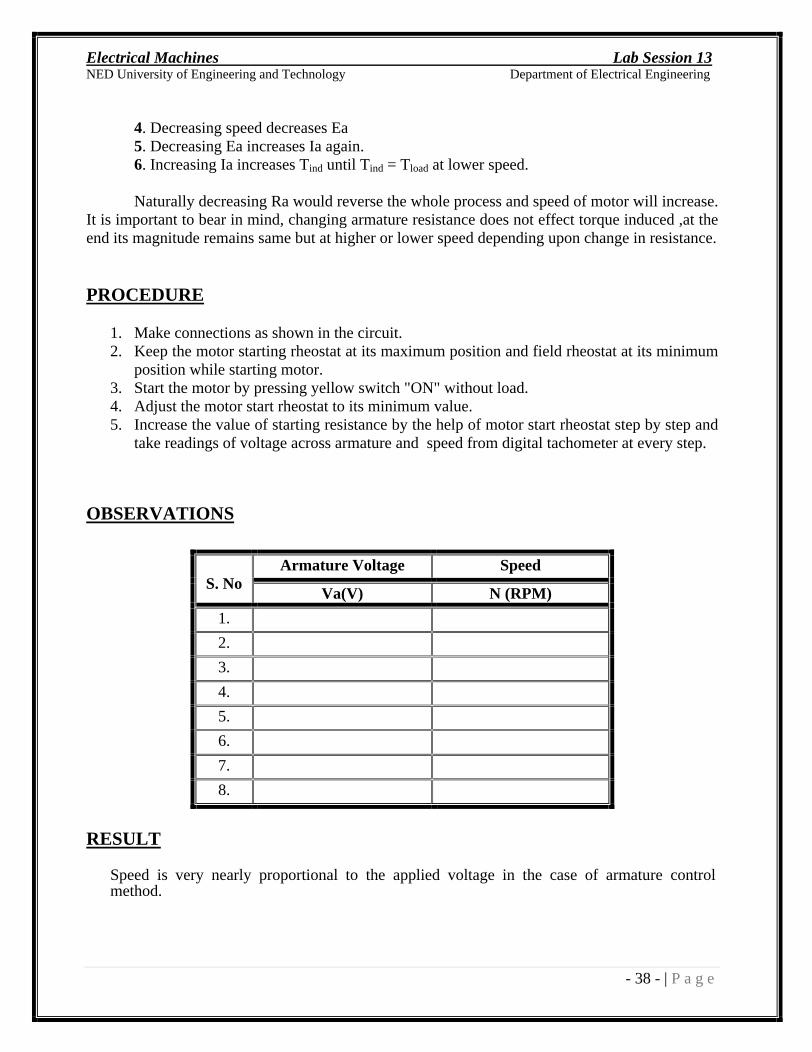
OBSERVATIONS
Armature Voltage Speed
S. No Va(V) N (RPM)
1.
2.
3.
4.
5.
6.
7.
8.
RESULT
Speed is very nearly proportional to the applied voltage in the case of armature control method.
Electrical Machines Lab Session 14
NED University of Engineering and Technology Department of Electrical Engineering
- 39 - | P a g e
LAB SESSION 14
OBJECT
To study the effect of field excitation on the generation of voltage by an alternator
(open circuit magnetization curve)
APPARATUS
1. Bench 12 ES/EV or Bench 13-ES/EV 2. DC multi-range ammeter 3. AC Voltmeter 4. Frequency meter
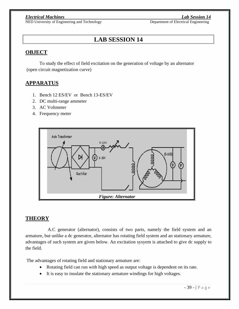
Figure: Alternator
THEORY
A.C generator (alternator), consists of two parts, namely the field system and an armature, but unlike a dc generator, alternator has rotating field system and an stationary armature, advantages of such system are given below. An excitation sysyem is attached to give dc supply to the field.
The advantages of rotating field and stationary armature are:
Rotating field can run with high speed as output voltage is dependent on its rate.
It is easy to insulate the stationary armature windings for high voltages.
Electrical Machines Lab Session 14
NED University of Engineering and Technology Department of Electrical Engineering
- 40 - | P a g e
It is easy to collect the high voltage from a fixed terminal.
Stator is outside of the rotor (fixed in yoke), so more space is available for 3-phase winding.
PROCEDURE
1. Make the connections as shown in figure 2. Excite the field with DC source 3. Adjust frequency of output to 50 Hz by adjusting speed of prime mover. 4. Nom increase the dc excitation current in steps. 5.
Tabulate the readings after every step and draw the open circuit characteristics (O.C.C) or no load magnetization curve.
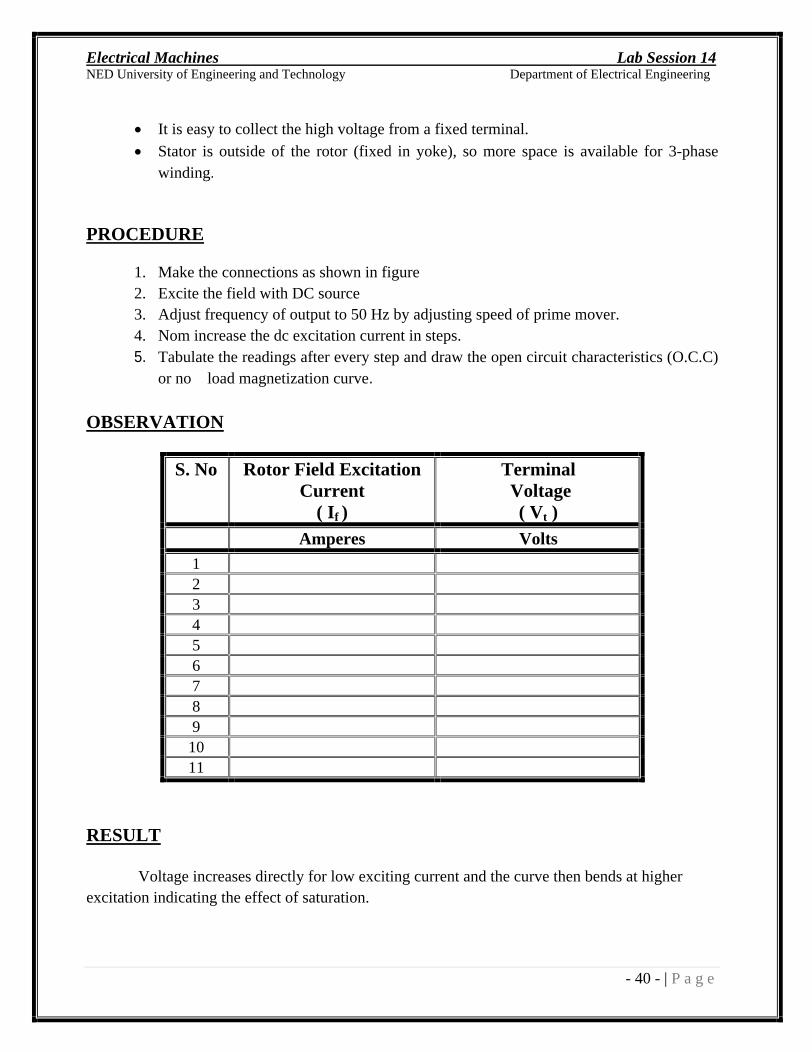
OBSERVATION
S. No Rotor Field Excitation Current
( If )
Terminal Voltage
( Vt )
Amperes Volts 1 2 3 4 5 6 7 8 9 10 11
RESULT
Voltage increases directly for low exciting current and the curve then bends at higher excitation indicating the effect of saturation.
Electrical Machines Lab Session 15
NED University of Engineering and Technology Department of Electrical Engineering
- 41 - | P a g e
LAB SESSION 15
OBJECT
To observe the starting of three phase Synchronous and Induction motor
APPARATUS
1. 3- Synchronous motor
2. 3- Induction motor
3. Variable 3- AC supply
4. DC Supply 5. Techometer
THEORY
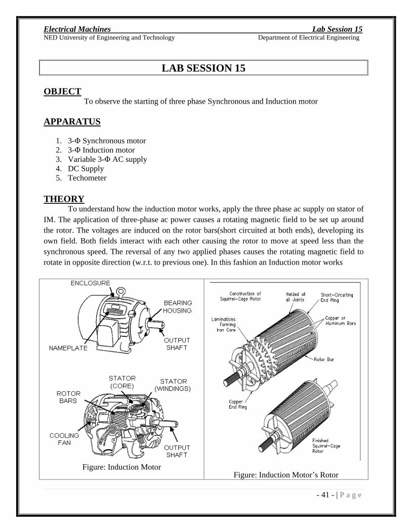
To understand how the induction motor works, apply the three phase ac supply on stator of IM. The application of three-phase ac power causes a rotating magnetic field to be set up around the rotor. The voltages are induced on the rotor bars(short circuited at both ends), developing its own field. Both fields interact with each other causing the rotor to move at speed less than the synchronous speed. The reversal of any two applied phases causes the rotating magnetic field to rotate in opposite direction (w.r.t. to previous one). In this fashion an Induction motor works
Figure: Induction Motor
Figure: Induction Motor s Rotor
Electrical Machines Lab Session 15
NED University of Engineering and Technology Department of Electrical Engineering
- 42 - | P a g e
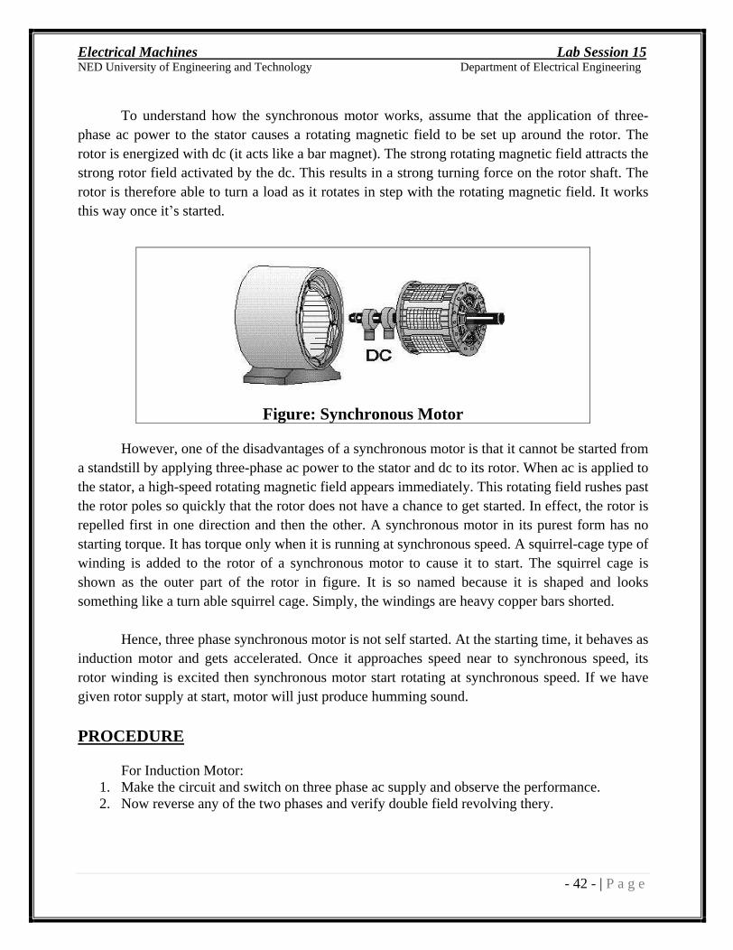
To understand how the synchronous motor works, assume that the application of three-
phase ac power to the stator causes a rotating magnetic field to be set up around the rotor. The rotor is energized with dc (it acts like a bar magnet). The strong rotating magnetic field attracts the strong rotor field activated by the dc. This results in a strong turning force on the rotor shaft. The rotor is therefore able to turn a load as it rotates in step with the rotating magnetic field. It works this way once it s started.
However, one of the disadvantages of a synchronous motor is that it cannot be started from a standstill by applying three-phase ac power to the stator and dc to its rotor. When ac is applied to the stator, a high-speed rotating magnetic field appears immediately. This rotating field rushes past the rotor poles so quickly that the rotor does not have a chance to get started. In effect, the rotor is repelled first in one direction and then the other. A synchronous motor in its purest form has no starting torque. It has torque only when it is running at synchronous speed. A squirrel-cage type of winding is added to the rotor of a synchronous motor to cause it to start. The squirrel cage is shown as the outer part of the rotor in figure. It is so named because it is shaped and looks something like a turn able squirrel cage. Simply, the windings are heavy copper bars shorted.
Hence, three phase synchronous motor is not self started. At the starting time, it behaves as induction motor and gets accelerated. Once it approaches speed near to synchronous speed, its rotor winding is excited then synchronous motor start rotating at synchronous speed. If we have given rotor supply at start, motor will just produce humming sound.
PROCEDURE
For Induction Motor: 1. Make the circuit and switch on three phase ac supply and observe the performance. 2. Now reverse any of the two phases and verify double field revolving thery.
Figure: Synchronous Motor

Electrical Machines Lab Session 15
NED University of Engineering and Technology Department of Electrical Engineering
- 43 - | P a g e
For Synchronous Motor:
1. Make the circuit and switch on both ac and dc supply and observe the performance. 2. Disconnect dc supply, switch on ac supply and observe the performance. 3. When motor run near to synchronous speed, which already calculated, switch on dc supply
also and observe the behavior.
OBSERVATIONS:
Speed of Induction Motor: rpm
Calculate: Slip speed =
Slip =
Speed of Synchronous Motor = rpm
EXERCISE:
Answer the following questions:
Why Induction motors have high starting current? ____________________________________________________________________________________________________________________________________________________________________________________________________________________________________________________________________________________________________________________________
Write three differences between Induction & Synchronous motor. _________________________________________________________________________________________________________________________________________________________________________________________________________________________________________________________________________________________________________________________________________________________________________________________________________________________________________________________________________________________________________________________________________________________________________