ee 100 dmm and dc power supply labview experiment...
TRANSCRIPT
EE100 Bharath Muthuswamy
1
EE 100 DMM and DC Power Supply LabVIEW Experiment Guide
1. Objectives The purpose of this experiment is to show you how to interface your DMM and DC Power Supply to LabVIEW. I. World of LabVIEW LabVIEW consists of many components – the Measurement and Automation Explorer, the LabVIEW, the Data Acquisition (DAQ) module, the NI 488.2 interface etc. In this class, you will be concerned with the Measurement and Automation Explorer, LabVIEW and the DAQ module. II. Using the Measurement and Automation Explorer First, let us verify that the multimeter and function generator are hooked up to the GPIB card in your computer. To do this, we will use the Measurement and Automation (M&A) Explorer. Please note: “click” means “left-click”.
1. Log into the computer station on your workbench (your TA should give you login instructions)
2. Start the M&A explorer: (see figure 1) Start→All Programs→National Instruments→Measurement and Automation
EE100 Bharath Muthuswamy
2
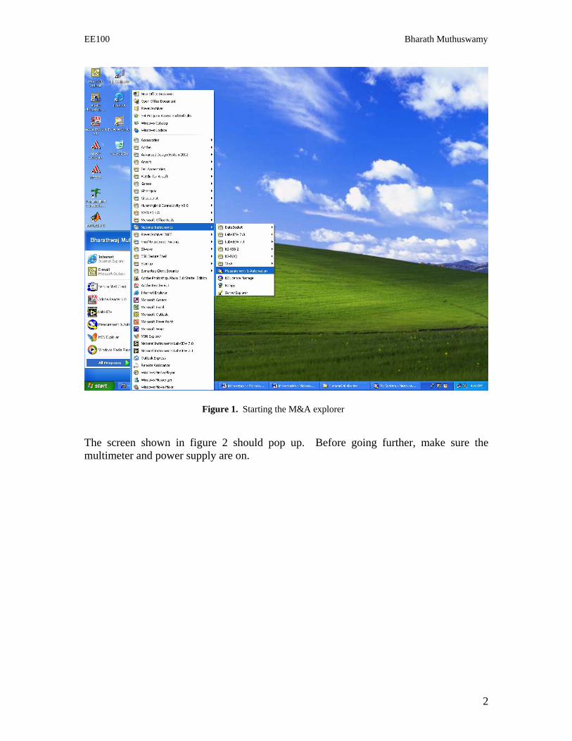
Figure 1. Starting the M&A explorer The screen shown in figure 2 should pop up. Before going further, make sure the multimeter and power supply are on.

EE100 Bharath Muthuswamy
3
Figure 2. The M&A explorer
3. Click on the “+” next to Devices and Interfaces to expand it. 4. Right click on GPIB0 (PCI-GPIB) and select Scan for Instruments as shown in
figure 3 (MAKE SURE THE MULTIMETER AND POWER SUPPLY ARE TURNED ON FIRST). The result on my computer is shown in figure 4.
Note: The exact GPIB bus number that is displayed will vary from computer to computer. The number may not be the same as mine. Please use YOUR bus number from now on in this lab guide. Once you interface to the instrument(s) from M&A explorer, you should see the multimeter screen show “Adrs and Rmt”. The power supply screen will show “Rmt”.

EE100 Bharath Muthuswamy
4
Figure 3. Scanning for instruments on the GPIB bus
Figure 4. Found two instruments: power supply (E3631A) on address 5 and multimeter (34401A) on 12. Once your instruments are recognized by the M&A explorer, proceed to the next section.

EE100 Bharath Muthuswamy
5
III. LabVIEW VI for the DC Power Supply and Multimeter Once you have interfaced to the instruments, the next step is to use LabVIEW VIs to talk to the instruments. First start LabVIEW (refer to figure 5):
1. Start→All Programs→National Instruments→LabVIEW 7.1→LabVIEW
Figure 5. Starting LabVIEW If the screen in figure 6 pops up, click Continue. You should see screen 7.

EE100 Bharath Muthuswamy
6
Figure 6. Starting LabVIEW
Figure 7. LabVIEW is ready for use Good news: VIs for your multimeter and DC power supply are already installed. You just have to learn how to use them!

EE100 Bharath Muthuswamy
7
a. LabVIEW setup for the DC Power Supply
1. Click the Open drop down box in figure 7. You should see figure 8.
Figure 8. The instrument VIs are in C:\Program Files\National Instruments\LabVIEW 7.1\instr.lib Navigate to the instr.lib directory as shown in figure 8. Figure 9 shows the instruments installed.

EE100 Bharath Muthuswamy
8
Figure 9. LabVIEW Instrument VI folders are listed by part number; these numbers are on the front panel of the instrument.
2. Double click on the hpe363xa folder. 3. Double click on the hpe363xa file. Two dialogs (refer to figure 10) will pop up.
Figure 10. Choose the HP3631A Getting Started VI
4. LabVIEW provides context sensitive help – the help comment will change depending on what you do. Moving the mouse cursor over a different element will give help related to that element. But first, double click on HPE3631A

EE100 Bharath Muthuswamy
9
Getting Started.vi to open up the LabVIEW VI. You choose the HPE3631A because that is the DC power supply you have on your work bench. The LabVIEW VI will open – see figure 11.
Figure 11. The LabVIEW front panel and other windows I will give a brief overview of the different components of a LabVIEW VI. Bear in mind this is only a brief overview – for details, you should refer to the Getting Started with LabVIEW document available from the EECS 40 LabVIEW homepage.
The most important component of the LabVIEW is the Front Panel. This is how you interface to your VI. The front panel will have pretty much the same components as a real instrument – buttons, knobs, displays etc. How do the components on the Front Panel actually work? To answer this question, click Window on the Front Panel menu bar and then click Show Block Diagram. Figure 12 will pop up.
Figure 12 shows the block diagram along with Sub VIs. As the name suggests, a sub VI is embedded within a bigger VI and does one task. Figure 13 shows the mouse cursor moved over the HP363xA Sub VI. The Context Help gives more information about the Sub VI. To open it, right-click the Sub VI and choose Open Front Panel.
You should continue to explore LabVIEW whenever time permits. In this introductory lab, we will just use the power supply and multimeter VIs.

EE100 Bharath Muthuswamy
10
Figure 12. The LabVIEW block diagram
Figure 13. The HPE363xA Initialize Sub VI

EE100 Bharath Muthuswamy
11
5. Close the block diagram by clicking on the in the top-right corner. 6. First, you need to set the correct GPIB address for the power supply in the
box. Enter the number by clicking in the box. 7. Now, lets set the output voltage and the current limit. Click in the Voltage box,
type 3 and press enter: . Click in the Current box, type 0.2 and
press enter: . 8. You are almost done! Run the VI by clicking on the button in the LabVIEW
toolbar.
You should see the display on the power supply change to reflect your settings. Congratulations! You have interfaced the DC power supply to LabVIEW. Next, I will show you how to interface the multimeter to LabVIEW. Please note: the steps involved in opening a VI for another instrument is the same procedure outlined on pages 1 through 11 of this lab guide. Hence, I will be referring back to these pages in the multimeter section of this guide and in other labs as well. To interface to the multimeter: 1. Click on File→Open from the HPE3631A Getting Started VI Front Panel menu
bar, as shown in figure 14.
Figure 14. Opening a new VI

EE100 Bharath Muthuswamy
12
2. Navigate to the HP34401A folder by clicking on . 3. Open the hp34401a library and choose the HP34401A Getting Started VI. Figure
15 should pop up.
Figure 15. The HP34401A Getting Started VI front panel
4. Type in the correct GPIB Address in: and make sure the
Interface is GPIB: .

EE100 Bharath Muthuswamy
13
3. Hands On a. Components Checklist Make sure you have the following components on your workbench BEFORE you begin the experiment. 1. Wires 2. Alligator clips or Banana plugs 3. Two 1 k resistors 4. One 10 k potentiometer b. Experiment In this experiment, you will be doing the same steps as Lab 1 – but you will be using LabVIEW. Therefore: i. Measuring DC voltage using the multimeter
a. Turn on the power supply and the your multimeter. Set your multimeter to measure DC voltage. USING YOUR LABVIEW DC POWER SUPPLY VI adjust your power supply to output 5 V and then 14 V.
b. USING LABVIEW MULTIMETER VI measure the two voltage values. ii. Use multimeter to measure some resistors and pots.
a. Measure the resistance of your 1 k resistor using your LabVIEW multimeter VI. b. Measure the resistance between the outer two legs of your potentiometer. c. Measure the resistance between the middle leg and any of the outer two legs of
your potentiometer.
iii. Simple series circuit.
a. Build the circuit shown in figure 16 on your breadboard. Set Vx to be 5 V (using the DC power supply VI) and R1 = R2 = 1 k.

EE100 Bharath Muthuswamy
14
Figure 16. Simple series circuit
b. Measure the voltage across and the current through R1 using the multimeter VI. iv. Simple parallel circuit.
a. Build the circuit shown in figure 17. Set Vx to be 7 V (using the DC power supply VI) and R1 = R2 = 1 k.
Figure 17. Simple parallel circuit b. Measure the voltage across and the current through R2.
v. Setting some VI parameters Let us use LabVIEW to set the precision of the multimeter:
a. Get a 1k resistor from your TA. In the HP34401A front panel, choose 2-wire
resistance measurement: .

EE100 Bharath Muthuswamy
15
b. Change the Range/Resolution to Manual: .
c. Choose the Manual Range to be a 1000 , and the resolution to
be 4.5 digits . d. Make sure the multimeter is powered on, the GPIB bus number in the HP34401A
front panel is correct and the multimeter is connected to the 1k resistance. Run the program and record the measurement from the multimeter.