eds 07-0003 enclosed major substation civil...
TRANSCRIPT
Document Number: EDS 07-0003
Version: 5.1
Date: 27/04/2015
TH
IS IS
AN
UN
CO
NT
RO
LL
ED
DO
CU
ME
NT
, T
HE
RE
AD
ER
MU
ST
CO
NF
IRM
IT
S V
AL
IDIT
Y B
EF
OR
E U
SE
ENGINEERING DESIGN STANDARD
EDS 07-0003
ENCLOSED MAJOR SUBSTATION CIVIL ENGINEERING STANDARD
Network(s): EPN, LPN, SPN
Summary: This standard details the Civil design and operational support equipment requirements of a major substation located in an urban environment with equipment and rooms housed partly or wholly below ground.
Author: Mark Dunk Date: 27/04/2015
Approver: Steve Mockford Date: 15/05/2015
This document forms part of the Company’s Integrated Business System and its requirements are mandatory throughout UK Power Networks. Departure from these requirements may only be taken with the written approval of the Director of Asset Management. If you have any queries about this document please contact the author or owner of the current issue.
Applicable To
UK Power Networks External
☒ Asset Management ☒ G81 Website
☒ Capital Programme ☒ UK Power Networks Services
☒ Connections ☐ Contractors
☐ Health & Safety ☒ ICPs/IDNOs
☐ Legal ☐ Meter Operators
☒ Network Operations
☐ Procurement
☐ Strategy & Regulation
☐ Technical Training

Enclosed Major Substation Civil Engineering Standard Document Number: EDS 07-0003
Version: 5.1
Date: 27/04/2015
© UK Power Networks 2017 All rights reserved 2 of 44
Revision Record
Version 5.1 Review Date 15/05/2018
Date 24/07/2017 Author Lee Strachan
Why has the document been updated – Minor version update re the withdrawal of EDS 07-0108
What has changed – References to EDS 07-0108 removed
Version 5.0 Review Date 15/05/2018
Date 27/04/2015 Author Mark Dunk
Why has the document been updated - Revised to update and provide clarity on the LV electrical and building services requirements.
What has changed –Section 3.4.3.1 re-titled, text reading ‘Fire lobbies are not required in UKPN sites’ added to Section 3.15, Section 3.15.2 re-titled, Complete update of Section 6, Appendix A updated. Appendix B Typical M&E SCADA Monitoring Points and Appendix C LVAC Incoming Supply Arrangement have been included.
Version 4.0 Review Date 29/11/2015
Date 14/03/2014 Author Mark Dunk
Document updated to accommodate and clarify issues raised during Capital Programme design and construction works
Version 3.0 Review Date
Date 24/10/2012 Author Mark Dunk
Document fully updated taking in revisions of Civils and Buildings specification. Document made G81 compliant. Review date extended for 3 years.
Version 2.1 Review Date
Date 6/09/2011 Author John Lowe
Document reclassified from ES to EDS
Version 2.0 Review Date
Date 30/12/2010 Author P. Linkeshwaran
Rebranded
Version 1.0 Review Date
Date 12/05/2010 Author Mark Dunk
Original
Enclosed Major Substation Civil Engineering Standard Document Number: EDS 07-0003
Version: 5.1
Date: 27/04/2015
© UK Power Networks 2017 All rights reserved 3 of 44
Contents
1 Introduction ......................................................................................................... 6
2 General Design and Planning Considerations .................................................. 7
2.1 Principal Requirement ............................................................................................... 7
2.2 Existing Sites ............................................................................................................. 7
2.3 Design Life ................................................................................................................ 7
2.4 Future Maintenance ................................................................................................... 7
2.5 Legislation ................................................................................................................. 7
2.6 Environment .............................................................................................................. 7
2.7 Operational and Working Clearances ........................................................................ 8
2.8 Health and Safety ...................................................................................................... 8
2.9 Electrical Equipment .................................................................................................. 9
2.10 Cable Entries and Routes .......................................................................................... 9
2.11 Security ..................................................................................................................... 9
2.12 Flooding .................................................................................................................. 10
2.12.1 Pluvial, Fluvial and Coastal ...................................................................................... 10
2.12.2 Water Main .............................................................................................................. 10
2.13 Fire Risk Assessment and Fire Plan ........................................................................ 11
2.13.1 Risk Assessment ..................................................................................................... 11
2.13.2 Fire Plan .................................................................................................................. 11
3 Substation Layout and Requirements ............................................................. 12
3.1 General ................................................................................................................... 12
3.2 Plant and Equipment ............................................................................................... 12
3.3 Design Loads .......................................................................................................... 13
3.3.1 Internal Overpressure .............................................................................................. 13
3.3.2 Floor Loads ............................................................................................................. 14
3.4 Transformer and Cooler Bays .................................................................................. 16
3.4.1 General ................................................................................................................... 16
3.4.2 Segregation of Transformers and Fire Suppression................................................. 17
3.5 Switchrooms ............................................................................................................ 18
3.6 Cable and Services Basement ................................................................................ 19
3.7 Auxiliary Room ........................................................................................................ 19
3.8 LVAC ....................................................................................................................... 19
3.9 Toilet ....................................................................................................................... 19
3.10 Store Room ............................................................................................................. 20
3.11 Mess Room and Switching Office ............................................................................ 20

Enclosed Major Substation Civil Engineering Standard Document Number: EDS 07-0003
Version: 5.1
Date: 27/04/2015
© UK Power Networks 2017 All rights reserved 4 of 44
3.12 Corridors and Stairs ................................................................................................. 20
3.13 Tunnel Shaft ............................................................................................................ 20
3.14 Materials and Plant Handling ................................................................................... 21
3.15 Fire Mitigation Measures and Escape Distances ..................................................... 21
3.15.1 Fire Escape ............................................................................................................. 21
3.15.2 Fire Detection and Alarm Systems .......................................................................... 22
4 Substation Materials and Specification ........................................................... 23
4.1 General ................................................................................................................... 23
4.2 Foundations ............................................................................................................ 23
4.3 Walls ....................................................................................................................... 23
4.3.1 General ................................................................................................................... 23
4.3.2 External Walls ......................................................................................................... 23
4.3.3 Internal walls ........................................................................................................... 24
4.4 Roofs and Floors ..................................................................................................... 24
4.5 Doors ...................................................................................................................... 25
4.5.1 Doors Generally: ..................................................................................................... 25
4.5.2 Fire and Security Rating of Doors ............................................................................ 25
4.5.3 External Doors ......................................................................................................... 25
4.5.4 Internal Doors .......................................................................................................... 26
4.5.5 Smoke Lobbies ........................................................................................................ 26
4.6 Cable Support Structures ........................................................................................ 26
4.7 Lifting Beam ............................................................................................................ 26
5 Building Works .................................................................................................. 27
5.1 Building Finishes ..................................................................................................... 27
5.2 Waterproofing .......................................................................................................... 28
5.3 Thermal Insulation ................................................................................................... 28
6 Building Services Requirements ...................................................................... 28
6.1 General Electrical .................................................................................................... 28
6.2 Incoming Supplies ................................................................................................... 28
6.3 Low Voltage Distribution .......................................................................................... 29
6.4 Distribution Boards .................................................................................................. 29
6.5 Lighting .................................................................................................................... 29
6.6 External Lighting ...................................................................................................... 30
6.7 Emergency Lighting ................................................................................................. 30
6.8 Small Power ............................................................................................................ 30
6.9 Fire Alarms .............................................................................................................. 31
6.10 Fire Suppression ..................................................................................................... 31

Enclosed Major Substation Civil Engineering Standard Document Number: EDS 07-0003
Version: 5.1
Date: 27/04/2015
© UK Power Networks 2017 All rights reserved 5 of 44
6.11 Lightning Protection ................................................................................................. 31
6.12 Earthing ................................................................................................................... 32
6.13 Heating .................................................................................................................... 32
6.14 Dehumidification ...................................................................................................... 32
6.15 Ventilation Duct Work .............................................................................................. 33
6.16 Smoke/Fire Dampers ............................................................................................... 33
6.17 Sound Attenuation ................................................................................................... 33
6.18 Damper Control Panel ............................................................................................. 34
6.19 Motor Control Panel ................................................................................................. 34
6.20 Building Management System (BMS) ...................................................................... 34
6.21 Intake and Exhaust Louvres .................................................................................... 34
6.22 Water and Drainage ................................................................................................ 35
6.23 Conduit Systems in General .................................................................................... 35
7 External Works .................................................................................................. 36
7.1 The Site ................................................................................................................... 36
7.2 Access ..................................................................................................................... 36
7.3 Drainage .................................................................................................................. 36
7.4 Transformer Delivery and Removal ......................................................................... 37
7.5 Switchgear Delivery and Removal ........................................................................... 37
7.6 Routes for Services ................................................................................................. 37
7.7 Cable Trenches ....................................................................................................... 37
8 Ground Finishes ................................................................................................ 37
9 Earthing .............................................................................................................. 38
10 M & E Testing and Maintenance ....................................................................... 38
11 Health and Safety File and As-built Information .............................................. 38
12 Reference Documents ....................................................................................... 39
Appendix A – Building Services Matrix ....................................................................... 40
Appendix B – Typical M&E SCADA Monitoring Points .............................................. 42
Appendix C – LVAC Incoming Supply Arrangement .................................................. 44
Enclosed Major Substation Civil Engineering Standard Document Number: EDS 07-0003
Version: 5.1
Date: 27/04/2015
© UK Power Networks 2017 All rights reserved 6 of 44
1 Introduction
This document describes in detail the standard building requirement for 132/33/11kV Enclosed Major Substations suitable for all three (SPN, LPN, EPN) licence areas where above ground space is at a premium. Enclosed Substations are any substations where elements and equipment are constructed or installed partially or wholly below ground or where ground level space restrictions require significant enclosures to plant. The principles of this design can be applied to all voltages and not specifically the transformation voltages quoted above.
Whilst standardization of civil design aspects is preferable, it is accepted that each project is specific. It is essential therefore that the civil design, whilst incorporating the requirements of this document, assesses each project design on its merits.
The designer must have due regard at all times to designing a substation that complies with all current UK Power Networks legislation and legal requirements.
Third party considerations, developers, local authorities etc. may influence the adopted design together with specific designers risk assessments, however it is essential that the requirements of this document are embedded within the final design.

Enclosed Major Substation Civil Engineering Standard Document Number: EDS 07-0003
Version: 5.1
Date: 27/04/2015
© UK Power Networks 2017 All rights reserved 7 of 44
2 General Design and Planning Considerations
This section outlines the issues and requirements that must be considered as part of the overall substation design and planning process
2.1 Principal Requirement
The principal function of the civil design is to provide buildings and structures to house and support the electrical equipment and ensure a safe environment for operational and maintenance staff who work within the substation and the safety of the general public.
2.2 Existing Sites
All measures to protect and ensure the continued operation of existing assets on the development site and/or on adjacent sites are to be taken.
2.3 Design Life
The main fabric of the structure should last not less than 50 years, with careful consideration given to minimum building maintenance throughout.
2.4 Future Maintenance
The design shall consider all future maintenance requirements together with possible addition and alterations to the installed plant. The design should provide adequate access to and around plant.
In addition to general maintenance, provision is to be made for the future removal and replacement of all plant. This provision shall include consideration for maintaining wayleaves and access agreements throughout the life of the substation.
2.5 Legislation
The substation must be designed to the current UK Power Networks policies, standards and legislation.
The design must also comply, where possible, with current British Standards, Building Regulations and the Town and Country Planning Act.
It may be possible to claim general permitted development rights for substation development under Class G, Section 17 of the Town and Country Planning (General Permitted Development) Order 1995.
Exemption from Building Regulations may be claimed under Schedule 2, Regulation 9 of The Building Regulations 2000 for Class II buildings. The exemption to Building Regulations enjoyed by statutory undertakers under Section 4 of the Building Act 1984 has been removed by Section 5 of the Sustainable & Secure Buildings Act 2004.
2.6 Environment
The design must have due consideration for the local environment and comply with the Environment Agency and Local Authority requirements.

Enclosed Major Substation Civil Engineering Standard Document Number: EDS 07-0003
Version: 5.1
Date: 27/04/2015
© UK Power Networks 2017 All rights reserved 8 of 44
2.7 Operational and Working Clearances
The design must meet UK Power Networks operational requirements as described in UKPN Distribution Safety Rules Section 4.
Adequate electrical and access clearances for each item of equipment are required in the plant layout. When planning structures carrying live electrical equipment, consideration shall be given to providing adequate Phase-to-Phase and Phase-to-Earth clearances as specified in BS 7354:1990. The minimum clearance distances are:
Voltage Operational
Clearance (m) Live Working Clearance (m)
Basic Electrical Clearance – Phase
to Earth (m)
Phase to phase clearance (m)
Up to 33kV 0.8 2.9 0.5 0.43
33kV to 66kV 1.0 3.1 0.7 0.78
66kV to 132kV 1.4 3.5 1.1 1.4
Note: Clearances are to be designed such that the minimum clearances are to the outside face of the conductor and not centre to centre
Minimum design clearances around plant to enable doors to open and free passage of people are:
Rear of switchgear 0.9m
Front of switchgear Depth of switchgear plus 200mm
Transformer 1m
132kV GIS CB 1m
These distances shall be considered the minimum but may increase in accordance with manufacturers’ layout requirements.
2.8 Health and Safety
The design must comply with all Health and Safety legislation and be safe to construct, operate and maintain at all times.
The design shall meet the requirements of the CDM (2007) Regulations and include:
Informing clients of their duties;
Design to minimise Health and Safety risks;
Provide all information about the Health and Safety risks of the design for the Health and Safety file;
Provide details of residual and operational risks;
The client shall appoint a CDM Co-ordinator for all the works at the commencement of the project;
Co-ordinate and communicate any information regarding significant risks associated with the design.
Enclosed Major Substation Civil Engineering Standard Document Number: EDS 07-0003
Version: 5.1
Date: 27/04/2015
© UK Power Networks 2017 All rights reserved 9 of 44
2.9 Electrical Equipment
The design must meet the technical and safety requirements for the plant and cables to be installed. Facilities must be provided for the delivery, offloading, handling and installation of plant and cables and for their possible future removal, additions or alterations.
Wherever practicable, electrical connections are to be made at high level in order to reduce the risk from interruption or damage by flood water.
All LV electrical installations shall comply with BS 7671 IEE Regulations and a compliance certificate must be obtained. The compliance certificate shall be retained on file, recorded on the UKPN Asset Register and, where possible, a copy displayed on site.
2.10 Cable Entries and Routes
The design must provide for the co-ordination of cable entries from outside circuits and for power and control cable routes within the substation. To include existing services and provision for future requirements.
Cables shall be installed in accordance with EDS 02-0031 ‘Installation of Power Cables and Joints Installed in Air’
Design guidance for typical minimum cable bending radii are given below:
132kV cables 3m
33kV cables 1.6m (single core XLPE)
11kV cables 1.2m
Control cables 0.6m
The cable entries are to be sealed against water ingress into the substation at the completion of the building construction. The sealing arrangement must be removable to enable the cables to be installed and the cable entries resealed.
Unless the outer sheath is specified as low smoke all exposed EHV, HV, LV, Control and Building Services cables within the substation shall be treated with intumescing paint or wrapped with flame retardant tape in accordance with UKPN document EDS 02-0031.
Duct banks are to be limited to a maximum of nine ducts and should enter/exit the substation by the maximum number of distinct routes possible.
A review of the services already present in the surrounding footpaths and roads shall be carried out in order to determine capacity for cable installation prior to any final decision regarding cable routes being made.
2.11 Security
Security provision will be advised by UK Power Networks Company Security. Where possible and safe to implement, the substation shall be designed with a single point of entry; all other doors and emergency exits shall be opened from the inside only with panic bars and shall have no external locking mechanism. External doors to meet Government Security Equipment Assessment Panel (SEAP) Class 3 standard or Loss Prevention Certification Board (LPCB) LPS 1175 level 4.
For a high risk substation and Critical National Infrastructure (CNI) sites, additional security measures may be required subject to confirmation by UK Power Networks Company Security
Enclosed Major Substation Civil Engineering Standard Document Number: EDS 07-0003
Version: 5.1
Date: 27/04/2015
© UK Power Networks 2017 All rights reserved 10 of 44
2.12 Flooding
2.12.1 Pluvial, Fluvial and Coastal
When considering the location of a new substation site it is essential, as well as considering the ecological impact and design suitability, that the risk from future flooding is assessed. Flooding can be caused by the rise of watercourses, breaches of Coastal defences and from surface water run-off, and these factors need to be investigated as part of the design process.
When assessing flood risk all of the following steps should be taken as a minimum:
Consider local and historical information about the site. Is the site known to be in a flood risk area, has the site been flooded before?
Investigate the surrounding area. Is the site close to a watercourse, however small? Is the surrounding land higher than the site? This could cause flooding from surface water run-off. Is the surrounding area likely to be developed / redeveloped in the future?
This again could impact on the degree of surface water run-off that could affect the site; hardstanding / hard landscaping in place of grassed/ soft landscaped areas will reduce the time and in which surface water reaches the site, and is also likely to increase the volume affecting the site.
Establish whether the site is within a known flood risk area from major watercourses. As part of the initial investigation the Environment Agency website provides maps indicating areas and degree of flood risk. The flood maps site can be accessed via www.environment-agency.gov.uk and typing in the post code of the potential site (or a nearby road) into the search box under the Flood Maps section.
If it is found that the proposed site is affected by flooding from any of these potential causes then ideally an alternative site should be sourced. In real terms however, this can not always be achieved and it therefore becomes essential that measures are put in place within the design in order to provide mitigation against the effects of flooding. Possible mitigation solutions include raising equipment and plant 400mm (to allow for wave action and environmentally related potential rises in flood level) above the predicted flood level or protecting/bunding the site or affected plant. The Government policy PPS25 should be consulted for guidance on the rules governing the permanent protection of sites.
Information regarding flood risk and levels can be obtained from the local Environment Agency office which can be contacted on 08708-506506 for all UK Power Networks licensed areas.
2.12.2 Water Main
Where Substations or individual items of plant are located below street level then the additional risk of flooding by burst water main or, to a lesser extent sewer, must be considered. In these cases the local water service provider should be contacted in order to establish the size, location and, where possible, age of any mains water feed in the locale of the proposed substation. The design is to incorporate protection against, or early warning of, these flood events where appropriate.

Enclosed Major Substation Civil Engineering Standard Document Number: EDS 07-0003
Version: 5.1
Date: 27/04/2015
© UK Power Networks 2017 All rights reserved 11 of 44
2.13 Fire Risk Assessment and Fire Plan
2.13.1 Risk Assessment
Prior to the handover of the substation to UK Power Networks Asset Management and Network Operations in compliance with the Regulatory Reform (Fire Safety) Order 2005, a competent and responsible person must make a suitable and sufficient Fire Risk Assessment of the risks to which relevant persons are exposed. For the purpose of identifying the general fire precautions they must comply with the requirements and prohibitions imposed on them by or under the Regulatory Reform (Fire Safety) Order 2005. It is essential that the Fire Risk Assessment and the Fire Plan mentioned below are developed in conjunction with the local Fire Brigade representative.
Further information regarding UK Power Networks responsibilities under this Order and other applicable Regulations and Acts, as well as guidance on separation distances and fire control and protection, can be found in UKPN document EDS 07-0116 - ‘Fire protection Standard for UK Power Networks Property and Operational Sites’.
2.13.2 Fire Plan
This will be specific to the premises and will detail the pre-planned procedures in place for use in the event of a fire. Again this is to be developed in conjunction with the local fire brigade representative.
The emergency plan must be recorded where:
A license under an enactment is in force;
An Alterations Notice under the Fire Safety Order requires it;
You are an employer and have five or more employees.
This shall (where appropriate) include the following features:
Action on discovering a fire;
Warning if there is a fire;
Calling the fire brigade;
Evacuation of the premises including those particularly at risk;
Power/process isolation;
Firefighting equipment (refer to Section 3.16);
Places of assembly and roll call;
Liaison with emergency services;
Identification of key escape routes;
Specific responsibilities in the event of a fire;
Training required;
Provision of information to relevant persons.

Enclosed Major Substation Civil Engineering Standard Document Number: EDS 07-0003
Version: 5.1
Date: 27/04/2015
© UK Power Networks 2017 All rights reserved 12 of 44
3 Substation Layout and Requirements
The substation is to accommodate all plant as dictated by the electrical design and output requirements and where necessary a tunnel shaft from the basement. The individual modules of the substation detailed in the Standard drawings are to be multiplied where appropriate and arranged to make the most efficient use of the space available.
The following sections detail the layout and requirements that are to be considered when designing an Enclosed Major Substation and the assumptions made during the development of the standard.
3.1 General
The function of the substation is to accommodate the electrical equipment in accordance with the supplier’s recommendations and UK Power Networks access requirements. Provision must be made for the possible addition and/or alteration to the equipment including plant from other suppliers.
The delivery route to switchroom and auxiliaries room is to be as level as possible with openings of a minimum of 1500mm wide x 2700mm high. Lifting beams of 2 tonne capacity are required where cabinets are required to negotiate changes in floor level.
Typically the substation shall provide the following principal rooms:
2no. transformer cells;
2no. cooler cells;
132kV switchroom;
11kV or 20kV switchroom;
Auxiliary room (including space for battery chargers and proposed Battery Air Conditioning (BAC) units);
LVAC Room (see Section 3.8);
Switching Office;
Fire suppression gas storage room;
Toilet with handwash;
Mess room;
Store room;
Cable basement.
3.2 Plant and Equipment
For illustration purposes only the following plant has been used as the basis for the Standard Enclosed Major Substation Civil Engineering design. Any variation or alteration to the plant design or quantities will lead to a requirement to alter details within the Civil Engineering site design while retaining the overall design principles.

Enclosed Major Substation Civil Engineering Standard Document Number: EDS 07-0003
Version: 5.1
Date: 27/04/2015
© UK Power Networks 2017 All rights reserved 13 of 44
Plant Manufacturer and Type Numbers
Transformer Wilson 66MVA 132/11/11kV with
separate coolers 2
Switchgear Siemens NX-PLUS
(Double bus-bar)
36 11kV Feeders
4 Transformer
incomers
2 Bus-couplers
2 Bus-sections
132kV Circuit-Breaker Siemens 8DN8 2
Neutral Earthing Resistor
(NER) / Neutral Earthing
Reactor (NEX)
4 (2/transformer)
Auxiliary Transformer 2
Table 1
3.3 Design Loads
Equipment suppliers such as those detailed above will give the mass and sizes of all ‘heavy equipment’ i.e. transformers, coolers, switchgear etc. specific to each project. These will include dismantled transportation mass. Allowances shall be made for equipment and cables hung from the roof and ceilings with regards to the overall load to these elements. Typical loads are shown below but these must be checked against the plant and equipment installed.
3.3.1 Internal Overpressure
A notional internal blast incident generated by an electrical fault requires the building fabric in the switchroom to be designed to retain integrity under a 5kN/m2 ultimate overpressure load internally. Materials are to be considered at ultimate strength.
Where calculations indicate that a switchgear fault could cause an overpressure greater than 5kN/m2, pressure relief in accordance with EDS 07-0111 ‘Switchroom Overpressure’ and EDS 07-0001 ‘Switchroom Overpressure Relief system’ shall be considered.
Around the transformers the building fabric and doors are to be designed to retain integrity under a 10kN/m2 ultimate overpressure load.
Fire damperson the ventilation systems, upon operation, are to contain overpressure up to 9.5kN/m2 from venting out through the ventilation ducting, see also Section 3.4.3.1
An overpressure event can occur during catastrophic failure of the plant and / or the release of fire extinguishing gases, overpressure containment and release systems shall be designed to accommodate all scenarios.
The building is to be designed such that the catastrophic loss of a wall will not result in building collapse or collapse of structures above the substation.

Enclosed Major Substation Civil Engineering Standard Document Number: EDS 07-0003
Version: 5.1
Date: 27/04/2015
© UK Power Networks 2017 All rights reserved 14 of 44
3.3.2 Floor Loads
Table 2 gives details of the minimum characteristic loads that the floors within the substation building are to be designed. Characteristic design loads are based on accommodating the equipment specified in Table 1. All other floor loads to be in accordance with BS 6399 -1 1996.
Item Location Minimum Characteristic Design Load Notes
1 Transformer
Bay
a) Operational weight of transformer on
the plinth
b) Operational weight of other plant
items in the bay
c) Bund area required to hold
transformer oil capacity +10% in
accordance with Environment Agency
document PPG2
d) Transformer pulling points: 2no
required on the back wall each
adequate for a horizontal load of 5%
of transformer weight. Sited approx
1.2m each side of the transformer
centreline at a height approx 600mm
above the top of the plinth
e) Floor of bay not occupied by plant
5kN/m2
f) Internal ultimate overpressure in an
enclosed bay 10kN/m2
a) Typical 132/11/11kV 66MVA
transformer weight is 1200kN
b) Typical auxiliary transformer and
NER weight is 2 Tonnes each
c) Oil relative density 0.9
2 Cooler Bay a) Operational weight of cooler on the
plinth
b) Operational weight of other plant
items in the bay
c) Floor of bay not occupied by plant
5kN/m2
a) Typical oil filled cooler weight is 250kN
on four feet
a) Typical water filled cooler weight is
150kN on 6 feet
3 Switchroom
11kV
a) Weight of switchgear in operational
position
b) Floor of switchroom not occupied by
plant – loading to suit plant delivery
Minimum 5kN/m2
c) Internal ultimate overpressure
5kN/m2
a) Typical 16.5kN/m2 (Siemens NX+
typical panel 18kN on
600x1800mm)
Alternative switchgear Eaton Holec
11kV 2000A Double Bus-bar panel
requires characteristic floor loads of
8.5kN/m2 (3kN Point Load)
b) As (a) plus 5kN point load (Typical
Siemens NX+ on four skates)

Enclosed Major Substation Civil Engineering Standard Document Number: EDS 07-0003
Version: 5.1
Date: 27/04/2015
© UK Power Networks 2017 All rights reserved 15 of 44
Item Location Minimum Characteristic Design Load Notes
4 Switchroom
132kV
a) Weight of switchgear in operational
position
b) Dynamic loads from switchgear
c) Floor of switchroom not occupied by
plant – loading to suit plant delivery
Minimum 5kN/m2
d) Internal ultimate overpressure
5kN/m2
a) Typical Siemens: 8ND8 teepoint.
Weight 10 tonnes on four legs at
approx 2m and 1m centres, or
Areva F35-2 Weight 10 tonnes on
12no feet spread over a floor area
2m x 3.5m plus a dynamic loads
(TBA)
b) Typical Areva F35-2: Vertical
dynamic load: 21kN at 26Hz over
0.35secs and Horizontal dynamic
load 17kN at 10Hz over 0.5
seconds
5 Cable and
Services
Basements
Floor 5kN/m2
6 Auxiliary
Room
a) Concrete floor: 10 kN/m2
b) Raised Access Floor as specification:
BS EN 12825:2001 Class 6/A/3/1
(this specification to be used for all
raised access floors in substations)
a) Typical cabinet is 5kN on plan
area 600x600mm = 14 kN/m2.
Allow for load spread over
600x1800mm add 5kN/m2 over
open floor = 9.6 kN/m2. Round up
to 10kN/m2
b) For a Class 6/A/3/1 floor panel
the ultimate load is 12kN, with a
maximum deflection of 2.5mm
under a working load with a
safety factor of 3 applied to the
ultimate load. Class 1 tolerances
7 LVAC Room Floor 5kN/m2
9 Toilet Floor 5kN/m2
10 Store Room Floor 5kN/m2
11 Mess Room
and
Switching
Office
Floor 5kN/m2
12 Corridors
and Stairs
To suit plant delivery loads
Minimum floor 5kN/m2
Table 2

Enclosed Major Substation Civil Engineering Standard Document Number: EDS 07-0003
Version: 5.1
Date: 27/04/2015
© UK Power Networks 2017 All rights reserved 16 of 44
3.4 Transformer and Cooler Bays
3.4.1 General
The delivery route for transformer is to be as level as possible and accommodate pulling points where required. The transformer plinth is to be designed to allow transformer jacking. Pulling eyes may be supplied and installed by the transformer delivery contractor. This requirement is to be checked as part of the design process and accommodated in the bund upstand/transformer bay wall design as appropriate.
Floor to be structural concrete sloping to sump, with plinth for transformer finished to the tolerance dictated by the transformer manufacturer, typically +/-3mm over a 5m straight edge.
Transformer floor to have centre lines marked on it to allow accurate positioning of transformers. Slab in transformer bay must be designed for jacking loads at each corner of the final transformer position.
Access hatch to be watertight so that water does not enter the cell.
Space shall be provided to facilitate the erection of a scaffold and the safe installation of temporary lifting equipment with which to remove transformer bushings, turrets and tap-changers. In addition a minimum 1200x1200mm clear floor area is to be provided to allow the lowering of the tap-changer to the floor for maintenance purposes; it is also recommended that a bespoke workbench, in accordance with the transformer manufacturer’s specification, is provided in conjunction with the transformer in order to facilitate tap-changer maintenance. Safe electrical clearance between structural elements and any exposed electrical equipment e.g. bushings and busbars, is to be maintained at all times (refer to Section 2.7).
Transformer dimensions to be matched to bay dimensions to give minimum access of 1000mm around the 132kV transformer, 2 no Neutral Earthing Reactors and Auxiliary Transformer. Access for maintenance of tap changer, pumps, control panels and ancillary equipment is to be considered.
Where transformers and/or coolers are not located at ground level stainless steel pipes are to be installed from a suitable point at ground level to the transformer and cooler bays to facilitate the topping up of the plant with oil; there should be 2No 25mm dia. pipes, one “Clean”, one “Dirty”. This requirement is intended to remove the need to transport oil barrels to and from the transformer and cooler bay areas.
Vertical distances between the coolers and the transformers greater than 8m will cause excessive pressure on the seals of the transformer where oil cooling is used. Where a cooler bay is to be positioned greater than 8m above the transformer a water cooling and heat exchanger system must be utilised.
Separate and segregated cooling systems are to be used for each transformer, air conditioning/chilling is not to be used in these locations.

Enclosed Major Substation Civil Engineering Standard Document Number: EDS 07-0003
Version: 5.1
Date: 27/04/2015
© UK Power Networks 2017 All rights reserved 17 of 44
3.4.1.1 Noise and Acoustic Housings
The site is to be assessed for noise pollution and noise mitigation measures (including noise suppression of cooler fans) agreed with the Local Authority where applicable.
A noise survey shall be carried out prior to the construction of the substation being commenced in order to establish a baseline noise level with which to assess post-commissioning levels.
After considering minimum safe clearances for operation and maintenance of the plant, the transformer bay shall be designed to avoid constructive wavelengths for frequencies of 100, 200, 400 and 800Hz. Constructive wavelength (λ) distances that can contribute to the noise level are considered to be 2λ, λ and λ/2.
Where significant noise reduction can be made or needs to be made, the distance between the transformer tank, the walls and the roof soffit should fall between the following figures:
0.915 -1.040m, 1.345 -1.600m, 1.750 -1.980m and multiples thereafter.
In addition to the spatial mitigation, transformer and coolers, where necessary, shall be surrounded with sufficient noise reduction elements to meet the local planning authority’s upper external noise criteria.
3.4.2 Segregation of Transformers and Fire Suppression
In accordance with the Electricity Council recommendations and UK Power Networks policy, enclosures around transformers shall be designed and constructed with a minimum four hour fire integrity resistance rating. Consideration should be given to risks at specific locations, to the provision of fire suppression methods and of four hour fire resistance separation for floor, walls and roof where debris or fire may affect a publicly accessible area. All structural elements and heat sensitive equipment located within the enclosure are to be insulated to 4hr resilience.
Where heat sensitive equipment or areas are located adjacent to the transformer enclosures 4 hour fire insulation is required over and above the integrity rating.
Consideration has been given to the risk of fire with transformer cooler areas. To date there have been no recorded cases of independent cooler fire within the history UK Power Networks or the individual licensed areas previously. By nature of the design it will be difficult to meet the four hour fire resistance rating where an acoustic housing is required around coolers and air inlet and exhaust areas are required. In light of this it is understood that any housing around a transformer cooler will only be expected to perform acoustically with no specific fire rating.
Fire detection and suppression shall be provided in all enclosed areas (areas not open to the air) where oil containing plant is located (see Section 6.8).
3.4.2.1 Fire and Overpressure Dampers
Dampers are to be supplied where required on all openings within the transformer bay. They are to be integrated into the fire alarm and detection system (see Section 6.8) and shall close upon the detection of fire. In order to prevent structural damage they shall be designed to re-open should the overpressure within the transformer bay exceed 9.5kN/m2 and reclose once that pressure drops below 9.5kN/m2.
In order to accommodate this requirement the ventilation system must be designed, specified and constructed to be able to contain and direct this overpressure to a safe point of release to the atmosphere away from publically accessible areas.

Enclosed Major Substation Civil Engineering Standard Document Number: EDS 07-0003
Version: 5.1
Date: 27/04/2015
© UK Power Networks 2017 All rights reserved 18 of 44
3.4.2.2 Oil Containment of Transformers (and Coolers)
Included in the information supplied by the transformer manufacturer will be oil volumes and weights. In accordance with Environment Agency document PPG 2 oil volumes are to be bunded to give 110% capacity of the total volume of oil in each cell assuming complete draining of the transformer and coolers, where oil filled coolers are used. Dependant on the arrangement of transformers and coolers, it may be necessary to construct separate bunds for each transformer and cooler. Floor and walls to the height of the bund volume are to be sealed with an oil resistant paint with preparation and priming as manufacturer’s specification.
Where transformer bays are open to the air or susceptible to ground water infiltration a sump 600 x 600 x 600mm is to be provided with an oil/water discriminating pump included in the design. The pump must have connections for remote alarm monitoring. Sump to be covered with 6mm thick galvanised steel chequer plate.
Outflow from the substation or transformer cells is to pass through a full retention separator as detailed in Section 7.3.3.
3.5 Switchrooms
For illustration purposes the standard switchroom is designed around a Siemens NXPlus double busbar switchboard comprising of 36 1250A feeders, 4 2000A transformer incomer, 2 2000A Bus-sections, 2 Bus-risers and 2 Bus-couplers. All designers must assess the layout and spatial requirements of the site specific switchgear type and arrangement as part of the design process in order to accommodate the switchboard and address operational and safety requirements.
Room dimensions and cable entry holes as required to suit manufacturers switchgear arrangement and minimum clearances as dictated by the manufacturer and Section 2.7 of this standard. Where a conflict occurs the largest dimension shall be used.
Steelwork switchgear support to be finished to a level and line tolerance In accordance with the details in Table 3, Section 5.1 Building Finishes.
Prior to arrival of switchgear the following sequence of work must be carried out in the switch-rooms:
Check slots/openings in slab for line and level to accept switchgear to be supplied and installed by others and make adjustments where necessary.
Complete building finishes, and clean the room.
An allowance is to be made in the 132kV switchroom height for the installation and operation of a travelling crane with a minimum 6t SWL. The exact dimension is to be in accordance with the manufacturer’s recommendations.
Facilities must be provided for the regular inspection and maintenance of the crane rails and associated lifting equipment.

Enclosed Major Substation Civil Engineering Standard Document Number: EDS 07-0003
Version: 5.1
Date: 27/04/2015
© UK Power Networks 2017 All rights reserved 19 of 44
3.6 Cable and Services Basement
The cable basement is to be of adequate size to accommodate all cables and cable radii and allow adequate working room for installation and maintenance.
Basement minimum headroom to beam soffits is 2.1m or the minimum bending radius of the cables required for cable installation whichever is the greater.
External basement walls to have cable ducts cast in at suitable positions for external circuits and sealed with expanding stopper.
Ducts to be capable of being sealed around cables installed by the cable contractor at a later date.
Basement soffit to have holes/opening to suit cable entry from plant and cable routes. Unistrut is to be cast into the soffit and basement walls to facilitate cable support installation (refer to paragraphs 4.6.2 a, b & c).
Floor to be finished to 1/100 falls to perimeter drainage channels, leading to sumps containing oil/water discriminating pumps.
There shall be a minimum of two points of staircase egress from the cable basement.
3.7 Auxiliary Room
Auxiliary room to be constructed to dimensions to accommodate cabinets required with minimum clear height of 3m under beam soffits. Unistrut is to be cast into the ceiling to facilitate cable support installation (refer to section 4.6.2a).
Wall space to be provided for cabinets and multicore cable terminations.
A solid concrete floor screeded to a finished level tolerance of ±1mm with a smooth dense surface over the area is to be provided for cabinet installation. Only top entry relay cabinets are to be specified.
Furniture: desk (1.5 x 0.9m), chair, filing cabinet (0.8 x 0.4m) and 3no wall key cabinets (1.0 x 1.0 x 0.1m deep).
VRLA batteries are to be used and space to accommodate the batteries and charger units must be allowed for within the Auxiliary Room. Plante cell batteries are no longer to be used due to maintenance and Hydrogen gassing issues.
3.8 LVAC
Where auxiliary transformers are specified, LVAC (415v 3 phase) panels shall be accommodated in the Auxiliaries Room, 1No for each Auxiliary transformer, 1No being supplied from the Network and 1No acting as a changeover switch. On sites where auxiliary transformers are not to be installed, design for 1No network LV supply.
3.9 Toilet
The toilet(s) will contain white or stainless steel sanitary fittings to be supplied with hot and cold water supply, chrome taps and foul water drainage.

Enclosed Major Substation Civil Engineering Standard Document Number: EDS 07-0003
Version: 5.1
Date: 27/04/2015
© UK Power Networks 2017 All rights reserved 20 of 44
3.10 Store Room
A storeroom for the storage of site specific tools and plant and equipment spare parts, warning signs and Earthing equipment is to be provided in the substation. The floor area is to be approximately 10m2.
3.11 Mess Room and Switching Office
Mess room is to be provided with:
Kitchen worktop 3m long with cupboards under and stainless steel inset sink with single drainer. Tiled splash-back 150mm high;
Wall mounted cupboard 1200mm long;
Hot and cold water and drainage to sink;
Dining table approx 2m x 1m and 6 chairs.
Switching office is to accommodate furniture: desk (1.5 x 0.9m), chair and 2no filing cabinets (0.8 x 0.4m).
3.12 Corridors and Stairs
Main corridors shall be a minimum of 1200mm wide. Switchgear/plant delivery requirements may dictate a larger corridor.
Stairs shall have a maximum rise of 190mm and a minimum going of 250mm. Nosing to be chamfered 12x12mm. Stairs are to be a minimum of 1200mm wide and include toe-plate/kick-plate in accordance with BS EN 14122.
Balustrades to be constructed from 48mm diameter mild steel tube and consist of handrail, mid-rail and uprights at centres not exceeding 1000mm. Uprights generally to be fixed to staircase string. Galvanised finish with rough edges removed.
Emergency egress points are to exit into open air at ground level. In areas above and below ground emergency egress can be into enclosed areas which have been designed as a place of safety and which have safe routes via stairs to the open air at ground level.
There is to be a minimum of two points egress from the substation ideally via staircases as detailed in above.
Emergency access and egress via ladders should only be provided where it is impossible to provide stairs. The ladder requirement shall be forwarded for approval to UK Power Networks at the outline design stage.
3.13 Tunnel Shaft
Where a tunnel shaft is required to be located on the Substation site the following considerations must be included in the final design following consultation of the UK Power Networks Cable Tunnel Design Manual.
Air ventilation route to tunnel shaft to be sealed off from the rest of the substation to minimise warm damp tunnel air permeating the substation and causing significant condensation problems Tunnel and shaft ventilation to be in accordance with the UK Power Networks Cable Tunnel Design Manual. All ventilation outlets shall be directed away from public areas.

Enclosed Major Substation Civil Engineering Standard Document Number: EDS 07-0003
Version: 5.1
Date: 27/04/2015
© UK Power Networks 2017 All rights reserved 21 of 44
Access and handling facilities to tunnel shaft to be provided for steelwork and cables together with personnel route. The shaft is to be fitted out with stairs, ladders and anchoring for fall arrest systems where appropriate. A hoist to the tunnel invert is required for plant access and emergency removal of injured persons.
Access to the tunnel shaft and tunnel shall be in accordance with UK Power Networks confined space procedures.
3.14 Materials and Plant Handling
The substation design must make space and handling facilities for the offloading, positioning and maintenance of all plant and equipment to be installed in the substation. Provision must also be made for the future removal and replacement of plant. Plant and equipment includes:
Transformers;
Transformer bushings, sealing ends, tapchanger, auxiliary transformer and neutral earthing reactors, coolers, fans, pumps and ventilation equipment;
132kV switchgear;
11kV switchgear;
Auxiliary room panels, Scada, relay panels, batteries and chargers;
205 Litre oil drums.
Additional access/plant movement equipment may also include:
Tunnel and shaft access by hoist and permanent crane of 500kg capacity;
Basement access by 5.5m x 2m hatch and 4 tonne lifting beam;
Check floor loading capabilities adequate for passage of all plant components.
3.15 Fire Mitigation Measures and Escape Distances
Building elements are to be designed for the following fire resistance periods:
Transformer bays – 4 hours;
Elsewhere – 1 hour.
Fire suppression system to be fitted to all enclosed areas with plant containing oil.
Fire lobbies are not required in UK Power Networks substation sites.
3.15.1 Fire Escape
Transformer and cooler bays, switchrooms and basement and other significant areas to have two exits signposted.
Personnel escape distances to meet Building Act 1984 Amended (2007) Building Regulations 2000 document B Volume 2 section 3: Horizontal Escape and section 4: Vertical Escape. Substations to be classed in Table 2 p34 as purpose group 6 industrial normal hazards. Horizontal escape distances where more than one escape direction the distance to be no greater than 45m and for only one escape direction distance to be no greater than 25m. Transformers are described in Appendix E p143 as special fire hazard needing 18m escape distance where two escape directions are available or 9m maximum escape distance if only one escape door is provided.

Enclosed Major Substation Civil Engineering Standard Document Number: EDS 07-0003
Version: 5.1
Date: 27/04/2015
© UK Power Networks 2017 All rights reserved 22 of 44
Direction signs to the nearest escape to be marked by photo-luminescent signs about 50mm diameter stuck to the floor.
3.15.2 Fire Detection and Alarm Systems
Fire detection and alarm systems are to be installed and maintained in accordance with BS 5839 Fire Detection & Alarm Systems for Buildings. Where appropriate an Aspirating Smoke Detection (ASD) system is to be used based on the Very Early Smoke Detection Apparatus (VESDA) system. The ASD system is to be designed and configured to be suitable for transformer enclosure and substation operation and to operate with minimal false alarms. Data on maintenance periods and procedures is to be provided by the manufacturer and / or Designer.
General fire mitigation measures to minimise fire fuel material shall be implemented e.g. install steel doors and avoid use of wood where possible.
Cable routes and other holes through walls and floors must be designed to be capable of being fire sealed after installation of all plant and cables.
The risk of independent cooler fire is considered low with no recorded cases in UK Power Networks history. In conjunction with the perceived ineffectiveness of a gaseous or water mist system in a bay open to the air it is not considered necessary to install a fire suppression system in transformer cooler bays where these are separate to the transformer. Where the risk of cooler fire continues to be a concern the use of water filled coolers complete with a heat exchanger shall be considered.

Enclosed Major Substation Civil Engineering Standard Document Number: EDS 07-0003
Version: 5.1
Date: 27/04/2015
© UK Power Networks 2017 All rights reserved 23 of 44
4 Substation Materials and Specification
4.1 General
Reinforced concrete construction to present a smooth dense true finish as BS 8110 cl.6.10.3 Type B with projections removed and holes filled in. Minimum 25mm chamfer on arises.
In accordance with the Electricity Council Recommendations with regards to transformers in enclosures, the roof and walls of the enclosures shall have a minimum fire resistance of 4 hours.
4.2 Foundations
To be designed to suit ground conditions and substation load together with consideration of tunnel shaft in basement.
Consideration for the Earthing layout (refer to Section 8.0) shall be given when designing and constructing the Substation foundations.
4.3 Walls
4.3.1 General
All walls, internal and external, are to match the doors installed in them in terms of fire rating and security (refer to Section 4.5.2).
4.3.2 External Walls
Above ground external walls to be designed to meet Building Regulations for thermal insulation except around the transformers where heat loss is encouraged. Typically a cavity wall with 100 internal skin of dense smooth faced blocks of compressive strength 7N/mm2, 80mm cavity with 30mm of insulation, and 102mm facing brick external skin to suit architectural requirements.
External below ground walls are to be constructed from reinforced concrete and designed to withstand:
Lateral earth pressures;
The overpressures mentioned in Table 2;
Loads from any buildings or structures constructed over the substation where these form part of the foundations of this structure. Advice is to be sought from the Structural Engineer regarding loads associated with this type of project.
In addition, external walls are to be waterproofed in accordance with Section 5.2.
Enclosed Major Substation Civil Engineering Standard Document Number: EDS 07-0003
Version: 5.1
Date: 27/04/2015
© UK Power Networks 2017 All rights reserved 24 of 44
4.3.3 Internal walls
To be one of following forms of construction:
Reinforced concrete;
215mm brickwork (class 4) Calcium Silicate/Sandlime smooth faced solid bricks in oatmeal or light colour;
140mm thick smooth faced solid blocks of strength 7N/mm2 (min density 1350kg/m3) and with 300mm square piers at doors, bed joint reinforcement. Perforated bricks or hollow blocks are not acceptable because of reduced carrying capacity for wall mounted equipment;
Brickwork and blockwork to be secured to concrete sections with ties and cast in/surface mounted channels and to be finished with a fair face and lightly pressed bucket handle joint;
Single sided Durasteel (or similar approved) partition on galvanised steel frame.
Windows or roof lights are not encouraged in order to maximise substation security.
Cladding only to be used if condition of Local Authority planning conditions or dictated to by developers. Irrespective of the external façade materials, an internal block wall, 2.0m in height, is required for surface fixing, protection of cladding and the mounting of ancillary electrical equipment.
No projecting corners of brickwork or climbing aids to be incorporated into the design.
4.4 Roofs and Floors
The roof construction shall suit the substation environment. It is to be insulated as required for building regulations except around the transformers where heat loss is encouraged. Above ground roofs are to utilise the Kingspan KS1000RW roofing system except over transformer and cooler bays where the roof, where required, is to be designed with a minimum four hour fire resistance fire rating. The roof is also to be designed to prevent debris, following catastrophic failure of a transformer, from entering a publicly accessible area.
The floor surface finish specified for each room is described in Section 5.1 (Table 3). In general the level requirement is a maximum gap of 5mm under a 3m straight edge laid anywhere on the floor. The switch-rooms and auxiliary room have specified very close level tolerances to suit plant installation requirements.
To suit cable routes, floors and walls are to have holes formed with non-metallic linings. Cast-in steel or ductile iron formers will not be acceptable. All cable holes and ducts must be free of obstructions, protruding nails, rough sharp edges or lips which could damage cables during the installation works.
Where openings in the floor are to remain open these are to be covered with a 25mm thick GRP or steel chequer plate panel with lifting openings, supported on a galvanised steel frame as specified.
Unistrut is required to be cast into the roof soffit along cable routes and around cable holes through floors to enable cables to be secured.
Where appropriate, all switchgear is to be secured to a steel frame over an opening in the switchroom floor. The steel frame is to be designed to accommodate the weight, size, cable and fixing layout and number of the switching panels as advised by the Electrical Engineer.
Where a raised access floor is to be used, either for access or as an alternative to the Auxiliary Room floor, a heavy duty flooring complying with BS EN 12825:2001 Class 6/A/3/1 is to be provided.

Enclosed Major Substation Civil Engineering Standard Document Number: EDS 07-0003
Version: 5.1
Date: 27/04/2015
© UK Power Networks 2017 All rights reserved 25 of 44
4.5 Doors
4.5.1 Doors Generally:
Doors/openings on the switchgear and auxiliary room delivery route are to have a clear opening suitable to accommodate the largest section of plant expected to pass along that route, minimum double door clear opening is 1.5m wide by 3m high, transom panels above the doors may be required to accommodate taller equipment;
The fire resistance rating of internal and external doors shall be in accordance with Section 4.5.2;
Double doors to have one passive leaf secured with tower bolts top and bottom and kept normally closed. Active leaf to be hinged and fitted with ironmongery in accordance with 4.5.3 and 4.5.4 below ;
Single doors to be a minimum of 800mm wide x 2100mm high Doors to open outwards for fire escape purposes and be self closing, preferably with rising hinges or fitted with a closing device;
External doors to be self locking. Internal doors are not to be self locking;
Doors from rooms containing operational plant are to be fitted with emergency escape devices to BS-EN 1125
Threshold strips to be let into the screed to ensure a smooth floor finish;
Heavy duty handles to be fitted to doors;
Dog/Hinge bolts to be fitted to all plant room doors. Hinges to be stainless steel ball bearing type low maintenance heavy duty hinges. All doors to be fitted with self closers;
All doors opening onto a wall are to be fitted with doorstops;
Steel frames to be fixed in brick openings with chemical resin fixings.
4.5.2 Fire and Security Rating of Doors
Fire rating: doors and frames generally are to be steel galvanised and powder coated complete with viewing panel (except when used as doors to toilet or shower) with fire ratings and specification:
Generally one hour fire rating;
Transformer and enclosed cooler cells four hour fire rating c/w viewing panel or porthole, smoke seals and be rated to resist an overpressure of up to 10kN/m2 (Booth Industries or similar approved);
Security rating for external doors only is to meet Government SEAP class 3 or LPCB LPS 1175 Level 4;
Doors to be equipped with either TDSi magnetic access system or locks matching the local area locking suite.
4.5.3 External Doors
All external single and double leaf doors to be certified to SEAP class 3/LPCB LPS 1175 Level 4. Doors to be complete with appropriate ironmongery including panic push bar escape door furniture (heavy duty Surelock McGill or similar approved) to BS EN 1125 to suit application and test certification;
Main doors to be access doors with external door furniture. All others are to be operated by internal panic bar systems only. The main access door is to have a locking system matching the existing intelligent, electronic key suite (preferred) and/or the UK Power Networks proximity card system. Where a fail secure solenoid locking and UK Power Networks TDSI access control system using a proximity card with PIN verification reader is used, a Key operated mechanical override should be installed to ensure access in the event of a power failure. Doors should be supplied pre-wired to an external point, as others will install the control system;

Enclosed Major Substation Civil Engineering Standard Document Number: EDS 07-0003
Version: 5.1
Date: 27/04/2015
© UK Power Networks 2017 All rights reserved 26 of 44
Sliding folding doors to be electrically operated sliding doors to SEAP Class 3/LPCB LPS 1175 Level 4 with a mechanical means to open them in the event of a power failure.
4.5.4 Internal Doors
Internal door furniture on rooms containing electrical plant and in corridors:
Internal single doors: escape panic bar and latch hardware internal to room and locking to suit local locking system on outside.
Internal double doors: dead leaf with escape panic bar and latch hardware internal to room.
Live leaf: as for single doors.
Internal doors on non-operational rooms (e.g. office, mess room stores) are to be provided with lever handles both sides and internal thumbturns for lock release. All internal doors with the exception of the Toilet and Shower Room doors to be powder coated steel c/w viewing panel. Toilet and Shower room access doors are not to have a viewing panel.
4.5.5 Smoke Lobbies
Smoke lobbies are not required unless at interface points where the substation is accessed / egressed though a 3rd Party occupied or owned building.
4.6 Cable Support Structures
Cable support structures shall be designed and installed by the cable installation contractor.
In order to provide fixing points for the cable support structures, galvanised Unistrut concrete inserts (P3270 41 x 41mm) are to be cast in concrete in the following locations:
a) At 1m centres in the soffits of the switchroom, auxiliary room and basement ceilings.
b) At 750mm centres vertically in the basement wall between the switchroom and the tunnel shaft.
c) Elsewhere as requested.
4.7 Lifting Beam
Lifting beams and trolleys shall be provided where required to negotiate changes of level on plant installation access routes and in the 132kV GIS Circuit-Breaker rooms.
Lifting beams and trolleys shall be of sufficient capacity to perform the lifting task required.
Provision shall be made in the design for access to inspect the lifting beam and crane rails where they are installed in accordance with LOLER 98 (Lifting Operations and Lifting Equipment Regulations 1998).

Enclosed Major Substation Civil Engineering Standard Document Number: EDS 07-0003
Version: 5.1
Date: 27/04/2015
© UK Power Networks 2017 All rights reserved 27 of 44
5 Building Works
5.1 Building Finishes
Finishes schedule as described below:
Room Floor Walls Ceiling
11kV Switchroom Heavy Duty Screed to a surface finish
level tolerance of ±1mm and painted
with heavy duty floor paint in light grey
or as advised
Or
Steel frame to locate and secure the
switchgear levelled to a tolerance of
±1mm; floor to be dust sealed and
painted with heavy duty floor paint
concrete levelled to +/- 3mm under a
5m straight edge.
None Dust sealer
Auxiliaries Room As 11kV Switchroom Primed and painted with
fungicidal vinyl silk
magnolia emulsion in 3
coats
Dust sealer
132kV Switchroom As 11kV Switchroom None Dust sealer
Transformer and Cooler
Bays
Float finish to tolerance of maximum
gap of +/- 3mm under a 5m straight or
as advised by the plant manufacturer /
installer
None None
Cable Basement Float finish to fall to drain None None
Mess Room Float finish to tolerance of maximum
gap of +/-3mm under a 5m straight
edge laid anywhere on the floor
painted with heavy duty floor paint in
light grey or as advised
As Auxiliaries Room Dust sealer
Toilet As for mess room As Auxiliaries Room.
Basins to have 300mm
white tiled splash back,
Dust sealer elsewhere
Dust sealer
Store, Corridor and
Steps
As for mess room None Dust sealer
Table 3
Enclosed Major Substation Civil Engineering Standard Document Number: EDS 07-0003
Version: 5.1
Date: 27/04/2015
© UK Power Networks 2017 All rights reserved 28 of 44
5.2 Waterproofing
Basement waterproofing to meet requirements of BS 8102:1990 Table 1.
Switchroom and Auxiliary Rooms to Grade 3: dry environment, with relative humidity less than 60%;
Other areas to Grade 2: no water penetration but moisture vapour tolerable;
Watertight sealing of all ducts with or without cable shall be carried out prior to commissioning.
5.3 Thermal Insulation
Thermal insulation shall be incorporated to ensure minimum ‘U’ values as recommended in the Building Regulations except around transformers and coolers where heat dissipation is required.
6 Building Services Requirements
Detailed below are the Building services requirement of the Enclosed Major Substation. Further details can be found in the Building Services matrix in Appendix A. All building services and building services management systems shall be simple to install and maintain.
6.1 General Electrical
The Distribution board is to be sited in the Auxiliary Room and building services circuits are to be taken from the board in surface mounted conduit or trunking.
The distribution board shall be the standard minimum 24 way TP&N board c/w 125A TP&N integral disconnector, fuse switches and control devices and supply all the low voltage equipment (including battery chargers) associated with the building services system
The LV supply shall be provided through a dual supply with auto changeover and a generator connection socket (at the LVAC board position(s)), one supply from each of the auxiliary transformers. Where multiple LVAC boards are necessitated, additional interconnection between boards shall be required in order to provide mutual support. All electrical installations to comply with BS 7671:2008 (IEE Wiring Regulations).
Technologically the building management system is to be kept as simple as possible and is to be developed in consideration with future ease of operation and maintenance.
The Building Management System is to provide alarms through SCADA for key systems only; these shall include fire alarms, fire suppression system operation, sump pump failure / high water and unauthorised entry, failure of LV supply.
6.2 Incoming Supplies
The incoming supply arrangement will depend on the type of substation. The supply arrangement for each substation type is detailed within Appendix C of this document.

Enclosed Major Substation Civil Engineering Standard Document Number: EDS 07-0003
Version: 5.1
Date: 27/04/2015
© UK Power Networks 2017 All rights reserved 29 of 44
6.3 Low Voltage Distribution
The LV switchboard (LVAC) shall be factory built assembly arranged to provide Form 4 Type 2 form of separation with degree of protection and as defined in BS EN 60439-1 and dust and water ingress protection of a minimum IP 31 rating.
The switchboard will be generally located in the auxiliary room equipped with all the necessary outgoing Fuse circuit protective devices. The switchboard shall be provided with a 100Amp standby generator connection via a commando socket to be provided to the panel. The switch board shall be sized for 20% spare capacity
The switchboard shall have the facility the interface with the UKPN SCADA system through volt free contact, see Appendix C for typical M&E SCADA Schedule
LV sub-mains distribution cables shall be XLPE/ SWA/ LSF, suitably sized to meet the maximum demand, fault rating, volt drop and taking into account all the relevant de rating factors. With the exception of the fire alarm, gas suppression, smoke damper and mechanical control panels which shall be fire enhanced cables
6.4 Distribution Boards
Distribution boards shall be a minimum 12 way TP&N board c/w 125A TP&N integral disconnector. The distribution boards shall be tested to IEC 60947 and will utilise a combination of outgoing miniature circuit breakers (MCB), residual current devices (RCD), residual current and over-current operated circuit breakers (RCBO) as required throughout.
All distribution board will be provided with approximately 20% spare way and supply capacity.
6.5 Lighting
Lighting throughout the substation shall be LED luminaires and suitable for the environment to be installed. Lighting level to be provided as detailed below and also to Appendix A. The lighting needs to be co-ordinated with plant installation and operation requirements and sited to suit the layout of the room and location of plant / equipment.
In specific areas the levels of illumination shall be in accordance with HSG 38 - Lighting at Work and CIBSE Code for Lighting as detailed below:
In 33 or 11kV switch rooms; 500 lux maintained luminance with a uniform factor of 0.8 across the front and rear elevation of all the switchgear, including spare bays;
In 132kV Switch room; 200 lux maintained illuminance with a uniform factor of 0.7 across the entire floor area;
In auxiliary rooms; 500 lux maintained illuminance with a uniform factor of 0.8 across the front and rear elevation of island panel suites and wall mounted equipment;
In cable basement;100 lux maintained illuminance with a uniform factor of 0.7 across the entire floor area;
In transformer bays 300 lux maintained illuminance with a uniform factor of 0.7 across the entire floor area;
In circulation areas and stairs 200 lux maintained illuminance.
Each switch location shall have a green neon indicator so they can be located in the dark.
Enclosed Major Substation Civil Engineering Standard Document Number: EDS 07-0003
Version: 5.1
Date: 27/04/2015
© UK Power Networks 2017 All rights reserved 30 of 44
6.6 External Lighting
External lighting shall be designed to ensure that external lighting is concentrated in the appropriate areas and that upward lighting is minimised, reducing unnecessary light pollution, energy consumption and nuisance to neighbouring properties, BS 1838
6.7 Emergency Lighting
The luminaires to be co-ordinated to provide average illumination on the floor level in accordance to CIBSE lighting guide and BS 5266 and BS EN 1838.
Emergency lighting system shall be provided by general luminaires complete with self-test integral maintained battery back-up of three hour duration or self-contained emergency light fittings.
Illuminated exit signs shall be provided within the building to indicate the direction of escape. Exit signs shall be located above external exit doors.
The system shall generally fulfil the following functions:
Indicate clearly all escape routes and provide illumination along such routes for safe movement under emergency conditions;
Ensure that fire alarm call points, firefighting equipment and any other safety equipment along escape routes can be readily allocated.
The design criteria will be generally as follows:
Escape routes 1.0 lux min
Anti-panic open plan areas 1.0 lux min
Type of operation Maintained/non maintained
Duration of operation 3 hours
6.8 Small Power
The small power installation will generally comprise of surface mounted 13A single and twin switched socket outlets, 13A fused connection units and isolators used for fixed items of equipment and mechanical plant including dedicated supplies to ancillary equipment.
Small power system layout shall be co-ordinated with plant installation, testing and maintenance requirements and with reference also to Appendix A.
Twin 13A socket outlets to be provided at approximately 20m intervals throughout the building with at least one in each room except toilets, corridors and staircases where they are no required.
32A SP&N Commando switched sockets to be provided at the rate of 1no in the switch room and transformer cells. These are required to supply lighting and power loads during construction and maintenance operations.
In each transformer cell one 63/100A, for three-phase, 400V supply is required for oil handling plant. Ingress protection for internal cells IP44 and IP65 for external cells these can be shared between cells depending on space separation.
Power supply as required to sump pumps, water heaters, heaters, dehumidifiers and other fixed appliances.
Enclosed Major Substation Civil Engineering Standard Document Number: EDS 07-0003
Version: 5.1
Date: 27/04/2015
© UK Power Networks 2017 All rights reserved 31 of 44
6.9 Fire Alarms
The substation shall be provided with a fire detection and alarm system within the building for the protection of life
An analogue addressable open protocol fire alarm detection system shall be provided throughout the building in accordance with BS 5839 Part 1. 2013. The category of protection shall be determined during the design stage.
All fire alarm equipment shall be manufactured by Companies approved by the Loss Prevention Certification Board and British Standard Approvals for fire equipment manufacture.
The wiring of the system shall be an enhanced fire alarm cable, coloured red.
6.10 Fire Suppression
Internal Transformer fire suppression shall be by Argonite, Inergen, FM-200 or similar approved gaseous system with main and reserve banks of cylinders designed, installed and commissioned in accordance with BS EN 15004:2008. The amount of extinguishant in the system shall be at least sufficient for the largest single hazard (normally one transformer bay); the reserve shall be of equal size.
Water mist and CO2 fire suppression systems are no longer accepted by UK Power Networks.
The system shall be operated by the fire suppression detection system. The detection system shall comprise of optical smoke detection and flame detection for each Transformer Bay.
Each bay shall have its own Fire Suppression control panel. The system shall be automatic and will be released when fire is detected in the protected area. The fire signal shall be double knock’ within the transformer bay.
The gas storage cylinders shall be located in a dedicated area within the substation.
The ventilation system from the Transformer Bay shall be provided with overpressure dampers located upstream from the smoke dampers. The vents shall be self-opening, using the forces of the gas suppression system within the space. The dampers shall open and close at a nominal pressure of 50Pa.
Interface with the Fire Alarm panel and SCADA system shall be via volt-free contacts see Appendix B of this document for details.
6.11 Lightning Protection
The system shall comply with all the current relevant statutory regulations and supporting codes of practice. These shall include but not limited to:
BS EN 62305;
BS EN 50164;
BS EN 61663.

Enclosed Major Substation Civil Engineering Standard Document Number: EDS 07-0003
Version: 5.1
Date: 27/04/2015
© UK Power Networks 2017 All rights reserved 32 of 44
Lightning protection system will be provided to cover the extent of the buildings such that it is the most economical system available and it complies with the requirements.
Where possible, the metal components of the roof construction including hand rails, plant, etc. will be used as the natural air termination network. The natural components of the air termination network, down conductors and earth terminations will be connected via proprietary lightning protection system components.
Where possible, the electrically continuous reinforced concrete framework of the structure and the façade elements, profile rails and metallic sub-constructions of the façade, will be utilised to form the down conductors.
6.12 Earthing
The substation facility will be provided with a comprehensive building services earthing system designed in accordance with BS 7671, BS 6651 and BS7430.
A main earth bar will be provided in the main switch room containing the main switchboard (LVAC). Removable links shall be provided for testing purposes. Equipotential bonding will be provided to satisfy BS 7671. IET Wiring Regulations 2008 17th Edition
6.13 Heating
Convector panel heaters are required in the switching office, mess room and toilet to be used on demand. Heaters to have timed switch-off facility and adjustable thermostat.
Convector heaters in switch rooms and auxiliary rooms to be thermostat controlled. The thermostat controlling the heaters shall be set at 10°C and locked off against tampering. A centrally located override switch with a four hour maximum timer shall be fitted to allow an increase in ambient room temperature to 21°C during occupation.
6.14 Dehumidification
In switch rooms and auxiliary rooms vapour compression type dehumidifiers shall be provided to prevent risk of condensation on switchgear. At least two dehumidifiers required in each switch room area in the event of duty dehumidifier failure. Waste water arising from the dehumidifiers is to be piped to a discharge drain. The dehumidifiers shall maintain a relative humidity of 55-60%.
Where air conditioning is required within the auxiliary room dehumidification should form part of the unit.
Interface with the SCADA system shall be via volt-free contacts see Appendix B of this document for details.

Enclosed Major Substation Civil Engineering Standard Document Number: EDS 07-0003
Version: 5.1
Date: 27/04/2015
© UK Power Networks 2017 All rights reserved 33 of 44
6.15 Ventilation Duct Work
All ductwork shall be designed to minimise noise, drumming, air turbulence, corrosion, ingress and egress of water, and air leakage. Ductwork shall be designed /constructed in accordance with HVAC document “Specification of Steel Metal Ductwork" ref. DW 144, Specification for Sheet metal Ductwork.
All ductwork and fittings within Transformer Bays will be of four hour fire resisting duct work fire resistant ductwork constructed of materials with an elevated rating of not less than 600°C or equivalent to the fire resistance rating of any compartment boundary. All other areas of the substation ductwork and fittings shall be constructed using 1 hour. ductwork.
Refer to Appendix A for Air Changes per hour (AC/Hr) and maximum and minimum temperatures.
All areas to be suitably ventilated with fire dampers to suit the ventilation scheme; dual ventilation systems in operational substation sites are not required by UK Power Networks; (this will be confirmed at the design stage)
Ventilation shall be designed to aid the temperature control in switch rooms in order to prevent overheating;
Automatic adjustable louvres are not required. Louvres are required fixed to suit design criteria;
Transformer bay ventilation to be designed in association with transformer manufacturer to minimise the risk of the bay temperature exceeding 40°C; air conditioning chillers are not required by UK Power Networks;
Toilet ventilation to outside;
Smoke extraction is only required for below ground areas. As described in BS9999 and Part B of the building regulations.
6.16 Smoke/Fire Dampers
Smoke dampers shall be sufficiently rigid to prevent fluttering or chatter. The leak rate from any damper shall not exceed 100l/s
The layout of the dampers shall take into account the maintainability of damper components such as access to the damper actuators and adequate clearance around the dampers for bearing inspection.
Dampers shall be provide with end switched to provide remote indication of opened and closed
Fire Dampers shall be in accordance with British Standard BS9999: should be held in the open position by means of a thermally actuated device set to operate at approximately 74 °C. Damper within the transformer bays shall be 4hr and capable of withstanding an over pressure of 9.6kPa
6.17 Sound Attenuation
Acoustic treatment shall be provided to ductwork as required. Sound attenuators shall be fitted on the inlet of supply fans and outlet side of extract fans. Where practicable, noise shall be treated at its source. High efficiency, low noise motors shall be used where possible to reduce noise. All acoustic treatment shall be fire resistant, inert, and non-combustible. All sound attenuation shall be capable of being cleaned in situ and demountable and capable of being removed for cleaning and access.
Enclosed Major Substation Civil Engineering Standard Document Number: EDS 07-0003
Version: 5.1
Date: 27/04/2015
© UK Power Networks 2017 All rights reserved 34 of 44
6.18 Damper Control Panel
Damper Control Panel shall typically consists of the appropriate number of switches to provide individual or group control, indication for status monitoring and all necessary relays and timers to comply with the site requirement needs for fully automatic damper operation.
6.19 Motor Control Panel
The motor control panel (MCP) is formed of two sections, comprising of a controlsection and
a power section; and is constructed to Form 2 will be cubical type factory built assemblies.
Fan motors shall be controlled by direct-on-line or assisted start as appropriate. Motor controls will contain facilities for plant status indication and for transmission of information to the Building Management Systems (BMS) where it is required.
The power section shall have the necessary MCB’s and electrical supplies for the main plant power requirements.
The control panel centre shall have the follow facia mounted controls/ indication:
Hand/off/auto;
Fan run;
Fan fault;
Control Panel live;
Filter Dirty.
6.20 Building Management System (BMS)
Where required the building management system is to be kept technologically as simple as possible and is to be developed in consideration with future ease of operation and maintenance. The BMS system shall be provided to:
Maintain design conditions throughout the zones;
Monitor the performance and operation;
Control equipment in a safe and stable manner.
6.21 Intake and Exhaust Louvres
Louvres should form part of the external building fabric, and shall meet the requirements of the planning application and Building Regulations.
All Louvres shall be sized for air velocity through the louvre of no greater than 2.5 m/s face velocity and shall not be less than 50% free area.
All external Louvres shall be suitable for continuous exposure to external weather conditions.
The louvres shall be manufactured from aluminium and be treated with a corrosion resistant coating.
All exhaust louvres shall be fitted with insect mesh to prevent entry by insects, vermin, birds, rodents and windblown extraneous material such as leaves, rubbish, and papers.
Enclosed Major Substation Civil Engineering Standard Document Number: EDS 07-0003
Version: 5.1
Date: 27/04/2015
© UK Power Networks 2017 All rights reserved 35 of 44
6.22 Water and Drainage
Adequate water supply and drainage to be provided to mess room and toilet;
The basement is to be drained by sump pumps to operating on an automatic float switch. These are to be sufficiently robust to deal with slurry and water, and deliver at least 1m³/hr to an adequate drain;
Consideration of a larger volume pump may be required should an assessment of tidal, fluvial or water main flood risk indicate a possibility of inundation (see Section 2.12);
An alarm is to be connected through SCADA to give warning of sump pump failure and potential high water levels. See Appendix B of this document for details
Refer to Sections 3.4.4, 7.3.2 and 7.3.3 regarding oil containment and interceptors;
Refer to HSS 01 007 for UK Power Networks policy on Site Drainage Systems.
6.23 Conduit Systems in General
Conduits shall be sized in accordance with the latest edition of BS 7671 with a minimum size of 20mm diameter.
Conduit can be either PVC or galvanised steel. PVC is conduit is to be used in all general applications; galvanised conduit is only be used in areas of impact high potential.
Use circular BESA boxes for drawing-in points, generally at two lengths of straight conduit or after two 90o sets, but without prejudice to BS 7671.
Install completely and swab-through the whole conduit system before any wiring commences. Do not pull cables round any box, burr or other source of abrasion.
Spacer bar type saddles shall generally be used throughout all installations. Finish to match conduit.
Maximum distances between conduit fixings are to be as follows:
Conduit size Steel PVC
20mm 1200mm 750mm
25mm 1200mm 750mm
Over 25mm 1500mm 900mm
In addition, fix conduits at points 250mm either side of a bend or set and 300mm from a switch, outlet box or any other termination.
Where distance saddles are used, the conduit boxes must be of the raised back type to maintain an even spacing behind the conduit.

Enclosed Major Substation Civil Engineering Standard Document Number: EDS 07-0003
Version: 5.1
Date: 27/04/2015
© UK Power Networks 2017 All rights reserved 36 of 44
7 External Works
7.1 The Site
The substation site must provide for:
Sufficient space for the ultimate envisaged number size and layout of plant;
Adequate access for plant as normally packaged and delivered by suppliers;
Underground cable entries;
Compliance with Local Authority planning requirements.
7.2 Access
Access is to be provided for the delivery, offloading and handling of all plant and cable drums as normally packaged by the suppliers.
Convenient access and parking for frequent visits by operational staff with van and equipment is required.
Plant access routes and handling equipment to all substation levels is required for:
Initial delivery at plant installation stage. The arrangements are to comply with plant suppliers, installers and commissioning requirements. An allowance is to be made to accommodate the one off delivery/removal of the transformers and associated delivery vehicle as advised by the plant haulage contractor;
Maintenance and operation requirements;
Future additional and/or changes of plant and cable routes.
Personnel access routes and car parking is required for frequent operational visits to the substation. Emergency escape routes are to be provided in accordance with Building Regulations 2000 (amended 2007) Document B Sections 3 with two exits provided from each transformer and cooler cell, and each switchroom and basement.
Maintenance access is required for the following vehicles:
Large vans approx size 6.4m x 2.1m x 3m high with 3.7m wheel base.
Mobile oil processing vehicle for maintenance of transformer oil. Tractor and trailer vehicle size: 15.2m long x 2.5m wide x 3.9m high includes trailer size 12m long x 2.5m wide x 3.9m high.
Access is required 24 hours-a-day and is to be unrestricted.
7.3 Drainage
The substation will require off site surface water and foul drainage.
The basement and substation areas with oil containing plant must have sumps with oil discriminating pumps delivering to the substation surface water drains or soak-away. The pumps installed are to be oil discriminating to a level of 5parts /million (5mg/l).
A Full Retention Oil Interceptor shall be installed between the substation drainage and the public drainage system to prevent oil contamination arising from substation activities. This separator shall conform to the Environment Agency PPG 3 guidelines and be purchased from one of the Environment Agency recommended manufacturers.

Enclosed Major Substation Civil Engineering Standard Document Number: EDS 07-0003
Version: 5.1
Date: 27/04/2015
© UK Power Networks 2017 All rights reserved 37 of 44
Of the two Classes of Oil Interceptor, Class 1 Interceptors are required when discharging into surface or controlled waters. Class 2 Interceptors are required when discharging into foul sewers.
Where flood water is discharged into a watercourse or sewer a Discharge Licence may have to be obtained from the Environment Agency or local sewer utility. It is possible that the Environment Agency may consider the water to be polluted and that treatment in the form of oil or silt removal may be required prior to discharge. If these treatment requirements cannot be met through the utilisation of the oil discriminating pump and interceptor, additional or alternative pollution control methods will have to be considered in the design and the overall total costs.
7.4 Transformer Delivery and Removal
Access routes must be provided and the delivery procedure agreed with the transformer haulage company. Access routes must be designed to accommodate the size and weight of the transformers and any plant/vehicles used in its delivery/removal.
The site must be kept clear of any features which interfere with the delivery or removal route e.g. trees and large items of street furniture.
7.5 Switchgear Delivery and Removal
Facilities for the delivery, installation and removal of switchgear and other plant must be designed to meet safe material handling considerations. The delivery procedure for major plant must be agreed with the installation company.
Off-loading facilities, such as lifting beams, should be permanently installed where possible to minimise the requirement for numerous mobile crane visits.
7.6 Routes for Services
The routing of all underground services (e.g. cables, drains, water, earthing) must be co-ordinated and included in the as built routes records.
Where possible, services shall be routed away from areas that may be used for heavy plant during the construction phase. If this is not possible then suitable protection must be provided.
7.7 Cable Trenches
Facilities for cable routes that will be installed after the substation is built, shall be provided so that any excavations or other works do not adversely affect the substation and road construction.
8 Ground Finishes
All ground surfaces around the substation are to be suitable for vehicle use and for safe pedestrian use. Pedestrian only areas are to be clearly marked and, where possible, segregated from areas of vehicle movement.

Enclosed Major Substation Civil Engineering Standard Document Number: EDS 07-0003
Version: 5.1
Date: 27/04/2015
© UK Power Networks 2017 All rights reserved 38 of 44
9 Earthing
Reference should be made to UK Power Networks’ Earthing Manual when designing and installing the Earthing system.
In sites within or below customer premises the substation earth shall be kept separate from the customer premises earth whenever possible.
The earthing requirement will be designed by UK Power Networks or their specialist consultant. It may require one or more of the following features to be installed with the substation building works:
Copper tape connection to steel sheet piles and/or steel reinforcement in foundation piles supporting the substation building.
a) A mat of earth tapes in the earth under the basement slab or around the substation.
b) A number of earth rods connected by earth tapes.
c) Earth tape terminations in the substation basement which are connected to external earthing systems described in (a) to (b) above.
The Earth system is to be installed at the same time as the construction of the substation. Substation fit out contractors will connect to the earth tape terminations described in (c) above.
Where any part of the Substation is above ground level and is considered to be at risk from a lightning strike the Lightning Protection System (LPS) must be designed and installed in accordance with BS EN 62305:2006 Parts 1-4 Protection against lightning. The LPS must be linked to the main Substation building Earth in order to prevent arcing during lightning strike conditions.
10 M & E Testing and Maintenance
Following installation and commissioning all M&E equipment shall be manually tested in operation.
All M&E equipment shall be supplied with a three year manufacturer or supplier backed warrantee providing routine and reactive maintenance and repair agreements.
11 Health and Safety File and As-built Information
Generic and site specific hazard risk assessments must be completed for all design elements and included in the final Health and Safety documentation for the substation.
Full as-built records shall be produced and shall be available at the time of hand over of the project. Records are to include:
Fully marked up as-built drawings detailing all structural and dimensional details;
Cables and circuits within the substation are to be clearly recorded and marked on the plans;
Feeds relevant but external to the substation are to be also recorded;
Maintenance periods and procedures and equipment supplier information are to be provided for all equipment and plant;
Hard-copy of the Health & Safety file to be made available on site.

Enclosed Major Substation Civil Engineering Standard Document Number: EDS 07-0003
Version: 5.1
Date: 27/04/2015
© UK Power Networks 2017 All rights reserved 39 of 44
12 Reference Documents
BS EN 62305:2006 Protection Against Lightning
BS 7671:2008 Requirements for Electrical Installations
BS 5266-1:2005 Emergency Lighting
BS 5266-7 / BS EN 1838:1999
Lighting Applications – Emergency Lighting
HSG38 Lighting at Work
CIBSE Code for Lighting
BS 6399-1:1996 Loading for Buildings
BS 8110-1:1997 Structural Use of Concrete
BS EN 12825:2001 Raised Access Floors
BS EN 1125 Building Hardware – Panic Escape Devices
BS 8102:1990 Code of Practice for Protection of Below Ground structures Against Water from the Ground
BS 5839-1:2002 Fire Detection and Fire Alarm Systems for Buildings
HSS 01 007 UK Power Networks Site Drainage Systems
PPG3 Environment Agency Guidelines on Separator Selection
PPS25 Planning Policy Statement 25 Development and Flood Risk
LOLER 98 Lifting Operations and Lifting Equipment Regulations 1998
CDM 2007 Construction (Design and Management) Regulations 2007
LPS 1175 Loss Prevention Certification Board – Loss Prevention Standard
SEAP3 Security Equipment Assessment Panel Class 3
EDS 02-0031 Installation of Power Cables and Joints in Air
EDS 02-0041 Tunnel Design Manual
EDS 06-0001 Earthing Standards
EDS 06-0013 Grid and Primary Substation Earthing Design
EDS 07-0001 Switchroom Overpressure Relief System
EDS 07-0111 Switchroom Overpressure
EDS 07-0116 Fire Protection Standard for UKPN Property and Operational Sites
Building Act 1984
Building Regulations 2000 (Amended 2007)
Regulatory Reform (Fire Safety) Order 2005
Sustainable & Secure Buildings Act 2005
Town & Country Planning (General Permitted Development) Order 1995
Town & Country Planning Act
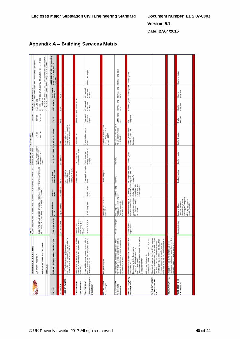
Enclosed Major Substation Civil Engineering Standard Document Number: EDS 07-0003
Version: 5.1
Date: 27/04/2015
© UK Power Networks 2017 All rights reserved 40 of 44
Appendix A – Building Services Matrix
NO
TE
S:
EX
TE
RN
AL
DE
SIG
N T
EM
PE
RA
TU
RE
S
EN
CL
OS
ED
MA
JO
R S
UB
ST
AT
ION
1. *
ind
icate
s s
pe
c f
rom
UK
Po
we
r N
etw
ork
s S
ub
sta
tio
n C
od
e o
f P
ractice
EI-
07
-01
05
db
=d
ry b
ulb
, w
b=
we
t b
ulb
Win
ter
Su
mm
er
No
tes
on
CIB
SE
re
fere
nc
es
:
ED
S 0
7-0
00
3 A
pp
end
ix A
C
IBS
E D
esig
n G
uid
e "
A"
-4ºC
db
2
8ºC
db
BU
ILD
ING
SE
RV
ICE
S M
AT
RIX
p
ag
e 1
He
ath
row
min
/max
Mo
nth
ly A
ve
19
48
-
20
09
-4.6
ºC d
b
28
.2ºC
db
3. C
IBS
E "
B"
ve
ntila
tio
n 2
.3.8
.2 C
om
munal re
sid
ential 1
air c
hang
e/h
r
Iss
ue
: 2
01
54
. C
IBS
E "
B"
Tab
le 1
.1 g
ive
s 1
6-1
9ºC
fo
r lig
ht w
ork
in f
acto
rie
s
SE
RV
ICE
GE
NE
RA
L S
PE
CIF
ICA
TIO
N IN
FO
RM
AT
ION
CA
BL
E B
AS
EM
EN
TT
RA
NS
FO
RM
ER
BA
YS
CO
OL
ER
BA
YS
11
, 2
2 &
33
kV
SW
ITC
HR
OO
MS
13
2k
V S
WIT
CH
RO
OM
AU
XIL
IAR
IES
RO
OM
TO
ILE
TM
ES
S R
OO
MS
WIT
CH
ING
OF
FIC
E
OT
HE
R A
RE
AS
: F
ire
su
pp
res
sio
n
ga
s r
oo
m, s
tore
s, s
tair
s &
co
rrid
ors
OC
CU
PA
NC
Yve
ry o
ccassio
nal
ve
ry o
ccassio
nal
ve
ry
occassio
nal
oft
en
occassio
nal
oft
en
oft
en
oft
en
oft
en
HU
MID
ITY
CO
NT
RO
LIn
11
kV
sw
itchro
om
and
auxili
ary
ro
om
s
co
mp
ressio
n typ
e d
ehum
idifie
rs a
re r
eq
uire
d to
main
tain
a r
ela
tive
hum
idity o
f 5
5-6
0%
.
co
mp
ressio
n typ
e
de
hum
idifie
rs to
main
tain
a r
ela
tive
hum
idity o
f 5
5-6
0%
co
mp
ressio
n typ
e
de
hum
idifie
rs to
main
tain
a
rela
tive
hum
idity o
f 5
5-6
0%
SP
AC
E H
EA
TIN
G
Fro
st
pro
tec
tio
n
Whe
re n
ote
d, co
nve
cto
r he
ate
rs to
be
the
rmo
sta
t
co
ntr
olle
d to
pe
rmane
ntly k
ee
p te
mp
era
ture
s
ab
ove
10
°C
Cab
le d
esig
n,
CR
AT
ER
to
asse
ss
cab
le r
ating
up
to
40
de
gC
min
imum
10
° C
13
2kV
sw
itchg
ear
sp
ecifie
d f
or
-25
de
g C
min
imum
10
° C
min
imum
10
° C
min
imum
10
° C
SP
AC
E H
EA
TIN
G
Pe
rso
nn
el o
cc
up
ati
on
of
su
bs
tati
on
On d
em
and
the
rmo
sta
t he
ate
rs r
eq
uire
d w
he
re
no
ted
, to
main
tain
min
21
ºC d
uring
occup
ancy
with 4
hr
tim
ed
cut-
out
No
Min
Te
mp
sp
ec
No
Min
Te
mp
sp
ec
No
Min
Te
mp
sp
ec
On d
em
and
the
rmo
sta
t
he
ate
rs
Plu
g in te
mp
ora
ry
he
ating
acco
rdin
g to
de
mand
On d
em
and
the
rmo
sta
t
he
ate
rs
On d
em
and
the
rmo
sta
t
he
ate
rs
On d
em
and
the
rmo
sta
t
he
ate
rs
On d
em
and
the
rmo
sta
t
he
ate
rs
No
Min
Te
mp
sp
ec
SP
AC
E C
OO
LIN
G
Pla
nt
he
at
ga
in
He
at g
ain
fro
m p
lant
28
kW
typ
ical fo
r 6
0M
VA
transfo
rme
r
40
W/s
qm
typ
ical
Estim
ate
d 4
0 W
/sq
m, 1
5%
batte
ry c
harg
er
outp
ut
ap
pro
x =
50
0W
SP
AC
E C
OO
LIN
G
for
pe
rso
nn
el
oc
cu
pa
tio
n
Sp
ace
co
olin
g f
or
pe
rso
nne
l o
ccup
atio
n w
he
re
max 4
0 d
eg
C is n
ote
d. S
eale
d f
or
life
batte
rie
s
req
uire
air c
ond
itio
nin
g to
main
tain
te
mp
era
ture
s
in the
rang
e 5
-25
de
g C
No
Max T
em
p s
pe
cM
ax T
em
p s
pe
c
40
de
gC
, air c
ond
itio
nin
g
/ chill
ing
is n
ot to
be
sp
ecifie
d o
r in
sta
lled
No
Max T
em
p
sp
ec
Max 4
0ºC
M
ax 4
0ºC
Max 4
0ºC
(if b
atte
rie
s a
re in
the
aux r
oo
m m
in/m
ax
10
~2
5d
eg
C )
No
Max T
em
p
sp
ec
No
Max T
em
p
sp
ec
No
Max T
em
p
sp
ec
No
Max T
em
p s
pe
c
VE
NT
ILA
TIO
N (
du
rin
g
oc
cu
pa
tio
n o
nly
)
Whe
re m
echanic
al ve
ntila
tio
n is insta
lled
it shall
be
de
sig
ne
d to
:
1)
sw
itch o
n a
t 3
0d
eg
C r
oo
m te
mp
2)
sw
itch o
ff a
t 2
0d
eg
C r
oo
m te
mp
3)c
ut o
ut o
n f
ire
ala
rm
4)m
anual o
n/o
ff o
ve
rid
e f
or
sm
oke
& g
as e
xtr
act
and
op
era
tor
co
mfo
rt
Min
imum
ve
ntila
tio
n 1
ac/h
Inle
t/o
utle
ts to
be
site
d a
way f
rom
pub
lic a
reas
se
e s
mo
ke
ve
nt
req
uire
me
nts
ac/h
r to
suit 4
0d
eg
C &
10
% h
eat lo
sse
s f
rom
transfo
rme
r o
pe
rating
at
2/3
maxim
um
cap
acity
for
the
site
Co
ole
r b
ay
ve
ntila
tio
n to
be
de
sig
ne
d in
asso
cia
tio
n w
ith
transfo
rme
r and
co
ole
r sup
plie
r.
Air c
hang
es to
suit m
ax
tem
p 4
0ºC
. M
in 1
air
chang
es/h
r
1 a
ir c
hang
es/h
rA
ir c
hang
es to
suit m
ax
tem
p 4
0ºC
. M
in 1
air
chang
es/h
r
6 a
ir
chang
es/h
r
6 a
ir c
hang
es/h
r1
air c
hang
es/h
r1
air c
hang
es/h
r
SM
OK
E E
XT
RA
CT
ION
IN U
ND
ER
GR
OU
ND
AR
EA
S
Whe
re e
xp
licitaly
sp
ecifie
d b
y U
KP
N to
co
mp
ly
with B
ldg
Re
gs D
ocum
ent B
. S
ectio
n 1
8. N
ote
18
.4, 1
8.8
, 1
8.1
3, 1
8.1
4.m
echanic
al sm
oke
extr
act re
quire
s 1
0 a
ir c
hang
es p
er
ho
ur.
In a
ll
circum
sta
nce
s s
mo
ke
extr
actio
n s
hall
be
und
ert
ake
n b
y the
sta
nd
ard
ve
ntila
tio
n s
yste
m.
FIR
E A
LA
RM
SY
ST
EM
Fire
de
tectio
n a
nd
ala
rm s
yste
ms a
re to
be
insta
lled
and
main
tain
ed
in a
cco
rdance
with B
S
58
39
Fire
De
tectio
n &
Ala
rm S
yste
ms f
or
Build
ing
s.
FIR
E D
ET
EC
TIO
N &
SU
PP
RE
SS
ION
Sm
oke
de
tectio
nS
mo
ke
and
he
at
de
tectio
n &
We
ight
mo
nito
red
Arg
onite
or
sim
ilar
ap
pro
ve
d s
yste
m
with m
ain
and
re
se
rve
banks o
f cylin
de
rs.
Sm
oke
de
tectio
nS
mo
ke
de
tectio
nS
mo
ke
de
tectio
nS
mo
ke
de
tectio
n
Sm
oke
de
tectio
n
Sm
oke
de
tectio
n
Sm
oke
de
tectio
n
2. B
EF
OR
E D
ET
AIL
DE
SIG
N S
TA
RT
S, S
PE
CIF
IC S
UB
ST
AT
ION
RE
QU
IRE
ME
NT
S
AR
E T
O B
E D
ET
ER
MIN
ED
BY
UK
PO
WE
R N
ET
WO
RK
S.
1. W
inte
r -4
ºC d
b is 2
4hr
ave
rag
e o
n 0
.7 o
ccasio
ns p
er
ye
ar
(se
ct
2.3
.1.2
fig
2.6
)
2. S
um
me
r 2
8ºC
db
is 1
% f
req
ue
ncy o
f ho
urly te
mp
exce
ed
ed
. (s
ect
2.4
.4 tab
le 2
.12
)

Enclosed Major Substation Civil Engineering Standard Document Number: EDS 07-0003
Version: 5.1
Date: 27/04/2015
© UK Power Networks 2017 All rights reserved 41 of 44
NO
TE
S:
EN
CL
OS
ED
MA
JO
R S
UB
ST
AT
ION
1. *
ind
icate
s s
pe
c f
rom
UK
PN
Sub
sta
tio
n E
ng
ine
ering
Instr
uctio
n E
I-0
7-0
10
5
ED
S 0
7-0
00
3 A
pp
end
ix A
BU
ILD
ING
SE
RV
ICE
S M
AT
RIX
p
ag
e 2
2. B
EF
OR
E D
ET
AIL
DE
SIG
N S
TA
RT
S, S
PE
CIF
IC S
UB
ST
AT
ION
RE
QU
IRE
ME
NT
S A
RE
TO
BE
DE
TE
RM
INE
D B
Y U
K P
OW
ER
NE
TW
OR
KS
.
Iss
ue
: 2
01
5
SE
RV
ICE
GE
NE
RA
L S
PE
CIF
ICA
TIO
N IN
FO
RM
AT
ION
CA
BL
E B
AS
EM
EN
TT
RA
NS
FO
RM
ER
BA
YS
CO
OL
ER
BA
YS
11
, 2
2 &
33
kV
SW
ITC
HR
OO
MS
13
2k
V S
WIT
CH
RO
OM
AU
XIL
IAR
IES
RO
OM
TO
ILE
TM
ES
S R
OO
MS
WIT
CH
ING
OF
FIC
E
OT
HE
R A
RE
AS
: C
O2
,
sto
res
, s
tair
s &
co
rrid
ors
LIG
HT
ING
Ge
ne
ral lig
hting
le
ve
l to
be
pro
vid
ed
as d
eta
iled
.
The
sig
hting
of
lighting
ne
ed
s to
be
co
-ord
inate
d
with p
lant in
sta
llatio
n a
nd
op
era
tio
n r
eq
uire
me
nts
.
*UK
PN
std
:10
0L
ux
0.7
unifo
rmity o
n f
loo
r
*UK
PN
Std
:30
0L
ux 0
.7u O
n f
loo
r:
17
0L
ux 0
.25
u
*UK
PN
Std
:cate
go
ry 2
lighting
5
00
Lux 0
.8u
ove
r fr
ont &
back o
f
pane
ls
20
0 L
ux 0
.7u o
n f
loo
r*U
KP
N S
td:c
ate
go
ry 2
lighting
5
00
Lux 0
.8u o
ve
r
fro
nt &
back o
f p
ane
ls
15
0 L
ux
30
0 L
ux
30
0 L
ux
15
0L
ux
Main
do
or
entr
ance
to
have
exte
rnal lig
ht w
ith P
IR to
op
era
te a
s d
oo
r is
ap
pro
ache
d.
EM
ER
GE
NC
Y
LIG
HT
ING
Em
erg
ency e
scap
e r
oute
lig
hting
of
1L
ux o
n f
loo
r
are
as a
s B
S5
26
6 p
t1 p
ara
6.3
.2. E
me
rge
ncy
lighting
fitting
s s
hall
be
in a
cco
rdance
with
BS
52
66
. E
me
rge
ncy lig
hting
to
be
pro
vid
ed
by
3hr
se
lf c
onta
ine
d n
on-m
ain
tain
ed
batte
ry
co
nve
rsio
n k
its h
ouse
d w
ithin
ge
ne
ral p
urp
ose
lum
inarie
s a
nd
em
erg
ency e
xit s
igns. L
um
inaire
s
no
t e
xce
ed
ing
15
m a
part
and
min
imum
2no
pe
r
roo
m
1 L
ux
1 L
ux
1 L
ux
1 L
ux
1 L
ux
1 L
ux
1 L
ux
1 L
ux
1 L
ux
1 L
ux
GE
NE
RA
L
PO
WE
R
Sm
all
po
we
r syste
m layo
ut ne
ed
to
be
co
-
ord
inate
d w
ith p
lant in
sta
llatio
n, te
sting
and
main
tenance
re
quire
me
nts
.Tw
in 1
3A
so
cke
ts to
be
pro
vid
ed
as a
min
imum
at 2
0m
inte
rvals
thro
ug
ho
ut th
e b
uild
ing
with a
t le
ast o
ne
in e
ach
roo
m e
xce
pt to
ilets
, co
rrid
ors
and
sta
ircase
s.
LV
sup
ply
fo
r sum
p
pum
p
1no
. 3
2am
p S
P&
N
Co
mm
and
o s
witche
d
so
cke
t
1no
. 6
3/1
00
am
p, 3
phase
, 4
15
vo
lt s
up
ply
is r
eq
uire
d f
or
oil
hand
ling
pla
nt.
(̂only
x1
63
/10
0
co
mm
on f
or
all
bays, if
bays d
o n
ot o
pe
n o
nto
pub
lic s
pace
)
do
ub
le 1
3am
p s
ocke
ts
to b
e p
rovid
ed
at 6
m
ce
ntr
es 1
no
. 3
2am
p
SP
&N
Co
mm
and
o
sw
itche
d s
ocke
t
1no
. 3
2am
p S
P&
N
Co
mm
and
o s
witche
d
so
cke
t
1no
. 1
00
am
p T
PN
sup
ply
po
int and
iso
lato
r to
be
pro
vid
ed
.
This
is r
eq
uire
d f
or
tem
po
rary
co
nne
ctio
n
of
test e
quip
me
nt
1no
. 3
2am
p S
P&
N
Co
mm
and
o s
witche
d
so
cke
t
Po
we
r to
he
ating
lig
hting
and
wate
r
he
ate
r
Po
we
r to
he
ating
lig
hting
and
wate
r
he
ate
r
Po
we
r to
he
ating
and
lighting
Po
we
r to
lig
hting
Po
we
r sup
ply
as r
eq
uire
d to
sum
p p
um
ps, w
ate
r
he
ate
rs, he
ate
rs, d
ehum
idifie
rs a
nd
oth
er
fixe
d
ap
plia
nce
s.
WA
TE
R S
UP
PL
Yho
t &
co
ld
wate
r sup
ply
ho
t &
co
ld
wate
r sup
ply
DR
AIN
AG
E*B
yp
ass s
ep
ara
tor
req
uire
d o
n s
ub
sta
tio
n
dra
inag
e o
utf
all:
Cla
ss 1
fo
r d
ischarg
e to
surf
ace
wate
rs
Cla
ss 2
fo
r d
ischarg
e to
fo
ul se
we
rs
Siz
e a
cco
rdin
g to
sub
sta
tio
n d
rain
ag
e a
rea.
dra
in to
dual sum
p
pum
ps to
op
era
te o
n
auto
matic f
loat sw
itch,
be
suff
icie
ntly r
ob
ust
to d
eal w
ith s
lurr
y a
nd
wate
r, a
nd
de
live
r at
least 1
m³/
hr
to a
n
ad
eq
uate
dra
in.
sin
k &
wc d
rain
sin
k d
rain
TE
LE
CO
MS
(ph
on
es
)
Se
e T
ele
co
mm
s (
LA
N)
2 p
oin
ts (
x1
fo
r p
ho
ne
,
x1
fo
r S
witchg
ear
Mo
de
m)
x1
fo
r p
ho
ne
x2
po
ints
(x1
fo
r p
ho
ne
, x1
for
RP
mo
de
m)
x2
pho
ne
(fo
r
pho
ne
and
fax)
TE
LE
CO
MS
(L
AN
)T
he
str
uctu
red
cab
ling
syste
m s
hall
co
nsis
t o
f a
sin
gle
cab
ling
sche
me
that can c
arr
y a
ll ty
pe
s o
f
traff
ic –
data
, vo
ice
. M
inim
um
Cate
go
ry 5
e
co
mm
unic
atio
ns c
ab
ling
shall
be
use
d to
co
nne
ct
the
RJ4
5 o
utle
ts to
a c
entr
al p
atc
h p
ane
l.
x3
LA
N (
x2
fo
r P
Cs, x1
in
TE
C p
ane
l)
x3
LA
N f
or
Se
curity
syste
m
(into
se
curity
pane
l).
Assum
ing
pane
l in
sta
lled
he
re
x2
LA
Nx2
LA
N
SE
CU
RIT
YB
uild
ing
se
rvic
es to
pro
vid
e f
or
UK
PN
se
curity
insta
llatio
n
Main
acce
ss d
oo
rs s
ho
uld
be
sup
plie
d p
re-w
ire
d to
an
exte
rnal p
oin
t

Enclosed Major Substation Civil Engineering Standard Document Number: EDS 07-0003
Version: 5.1
Date: 27/04/2015
© UK Power Networks 2017 All rights reserved 42 of 44
Appendix B – Typical M&E SCADA Monitoring Points
No. of Signals Output
a)
Fire Alarm Operated 1 X
Fire Alarm Fault 1 X
b) Gas suppression panel Tx1
Gas Discharged 1 X
Fault 1 X
Non Auto 1 X
c) Gas suppression panel Tx2
Gas Discharged 1 X
Fault 1 X
Non Auto 1 X
d)
Extract Fan - Fault 1 X
Supply fan - Fault 1 X
Supply Fan - Filter Dirty 1 X
Hi-limit temperature alarm - TX Bay 1 1 X
e)
Extract Fan - Fault 1 X
Supply Fan Fault 1 X
Supply Fan - Filter Dirty 1 X
Hi-limit temperature alarm - TX Bay 2 1 X
f)
Ventilation Fan - Fault 1 X
Ventilation Fan - Filter Dirty 1 X
Hi-limit temperature alarm - 1 X
Dehumidifier DH1 - Fault 1 X
Dehumidifier DH2 - Fault 1 X
g)
Ventilation Fan - Fault 1 X
Hi-limit temperature alarm 1 X
Ventilation Fan - Filter Dirty 1 X
h)
Ventilation Fan - Fan Fault 1 X
Ventilation Fan - Filter Dirty 1 X
Hi-limit temperature alarm 1 X
Air-conditioning - Fault 1 X
Dehumidifier DH3 - Fault 1 X
Dehumidifier DH4 - Fault 1 X
Alarm and fault - Cable Basement
Alarm and fault - Auxiliary Room
Fire alarm panel
Alarm and fault - Transformer 1
Alarm and fault - Transformer 2
Alarm and fault - Switch Room
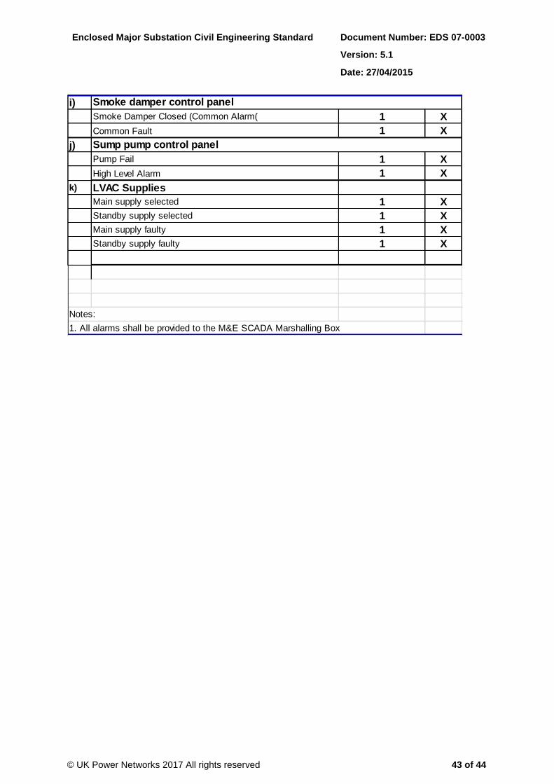
Enclosed Major Substation Civil Engineering Standard Document Number: EDS 07-0003
Version: 5.1
Date: 27/04/2015
© UK Power Networks 2017 All rights reserved 43 of 44
i)
Smoke Damper Closed (Common Alarm( 1 X
Common Fault 1 X
j)
Pump Fail 1 X
High Level Alarm 1 X
k) LVAC Supplies
Main supply selected 1 X
Standby supply selected 1 X
Main supply faulty 1 X
Standby supply faulty 1 X
Notes:
1. All alarms shall be provided to the M&E SCADA Marshalling Box
Sump pump control panel
Smoke damper control panel

Enclosed Major Substation Civil Engineering Standard Document Number: EDS 07-0003
Version: 5.1
Date: 27/04/2015
© UK Power Networks 2017 All rights reserved 44 of 44
Appendix C – LVAC Incoming Supply Arrangement
1no. LV network supply
2no. LV network supplies from
two different HV feeders with
(manual changeover)
2no. LV network supplies from
two different HV feeders
(auto changeover)
LV supplies from auxiliary
transformers with
(manual changeover)
LV supplies from auxiliary
transformers with
(auto changeover)
X
X
X
X
X
X
X
X
X
Cable tunnel with forced ventilation
Cable tunnel without forced ventilation
Note 1 where a changeover arrangement is
provided then its essential each supply is
capable of supplying the whole site load.
Note 2 minimum no of supplies for any auto
changeover is n-1
33/11kV Primary substation without
transformer forced cooling
66/11kV Grid substation with transformer forced
cooling
66/11kV Grid substation without transformer
forced cooling
132/11kV Grid substation with transformer
forced cooling
33/11kV Primary substation with transformer
forced cooling
Site Description
33kV Primary substation without transformer(s)
11kV Primary substation without transformer(s)