edl 1405 manual
TRANSCRIPT

1 Edelbrock Performer Series Carburetor Owner’s Manual 3/00
INTRODUCTIONYour Edelbrock Performer Series carburetor was calibrated using Edelbrock Performer, PerformerRPM, and Torker II Power Packages. The carburetor metering was developed on Edelbrock enginedynamometers, chassis rolls, and a variety of development vehicles. Although in most applicationsyou will not need to recalibrate your carburetor, you may wish to change the factory calibration to bestmeet any unique needs of your engine. The following manual consists of 2 sections; Theory ofOperation and Tuning Procedure. Upon review of Section 1, Theory of Operation, you will be preparedto develop your own individualized calibration. Section 2, Tuning Procedures will take you through astep-by-step procedure that will enable you to achieve a desirable calibration. For added ease oftuning, a Calibration Reference Chart for your model of carburetor has been included.
TABLE OF CONTENTS
SECTION 1: THEORY OF OPERATION .......................................................................2BASIC ENGINE REQUIREMENTS ............................................................2METERING SYSTEMS............................................................................3
1. Idle System ..............................................................................32. Primary Main System ................................................................43. Secondary Main System............................................................6
TRANSIENT CONTROL SYSTEMS ..........................................................61. Secondary Auxiliary System .....................................................62. Pump System ...........................................................................7
EXTERNAL DEVICES..............................................................................8Fuel Pumps and Pressure..............................................................8Air Cleaners ..................................................................................9
SECTION 2: TUNING PROCEDURE ............................................................................9REVISING THE CALIBRATION.................................................................9
Parts and Equipment ..................................................................10Changing Components ................................................................11
IDLE MIXTURE ....................................................................................11Winter Fuel Idle Sets ..................................................................11Long Duration Camshaft..............................................................12
CALIBRATING THE WIDE-OPEN THROTTLE (WOT) ............................................................12CALIBRATING THE PART THROTTLE....................................................13
Cruise Mode................................................................................13Power Mode ...............................................................................14
CALIBRATING THE POWER MODE STAGING.........................................14CALIBRATING THE PUMP ....................................................................14FLOAT ADJUSTMENT .........................................................................14CHOKE ADJUSTMENT.........................................................................15SPECIAL CALIBRATIONS ....................................................................16CARBURETOR SPECIFICATIONS ....................................................16, 17CALIBRATION REFERENCE CHARTS...............................................18-31APPENDIX .....................................................................................32-38
Exploded View.......................................................................32, 33Troubleshooting Information. .................................................34-36
WARRANTY .......................................................................................37EDELBROCK CARBURETOR DATA LOG ...............................................38
1403-1413 Perf Series Carburetor Owner's Manual.qxd 3/31/2006 12:05 PM Page 1

2 Edelbrock Performer Series Carburetor Owner’s Manual 8/94
SECTION 1: THEORY OF OPERATION
BASIC ENGINE REQUIREMENTS
The spark-ignition 4-cycle engine burns a mixture of AIR and FUEL. The air is controlled by thedriver’s operation of the throttle. The fuel is mixed with the incoming air by the carburetor. The Ratioof AIR to FUEL is the AIR/FUEL Ratio (A/F). This is a ratio by WEIGHT; if 12 pounds of Air are combinedwith 1 pound of Fuel the A/F is 12:1, or more commonly, A/F = 12.
Despite the enormous variety in engine designs, virtually all (spark-ignition 4-Cycle) engines havevery similar A/F Ratio requirements. For fully warmed-up engines, the range of A/F is:
A/F RATIO CHARACTERISTICS
5 RICH BURN LIMIT: Combustion is weak/erratic.
6-9 EXTREMELY RICH: Black smoke and low power.
10-11 VERY RICH: Some supercharged engines run in this range at full power as ameans of controlling detonation.
12-13 RICH: Best power A/F: Un-supercharged WOT.
14-15 CHEMICALLY IDEAL: At 14.6 the A/F is at the theoretical ideal ratio with noexcess fuel or oxygen after combustion. Good A/F for part throttle cruise and light to moderate acceleration.
16-17 LEAN: Best economy A/F ratio. Borderline for part throttle drivability (worse than borderline if EGR is used).
18-19 VERY LEAN: Usual lean limit (Driveability).
20-25 LEAN BURN LIMIT: Varies with engine and system.
Even though engines will run anywhere between 5 and 25 A/F, the usual target values for an un-supercharged engine are a fairly narrow range (Figure 1). A/F is about 12.5 for the WOT and 14.0-15.5 at part-throttle cruise. An intermediate value of about 13.5-14.0 is usually used for mid-rangepower (non-WOT acceleration).
1403-1413 Perf Series Carburetor Owner's Manual.qxd 3/31/2006 12:05 PM Page 2

3 Edelbrock Performer Series Carburetor Owner’s Manual 8/94
METERING SYSTEMS
The Edelbrock carburetor has three (3) basic systems that meter fuel to the engine: The Idle System,Primary Main System, and Secondary Main System. By understanding the operation of each you willbe better prepared to calibrate your carburetor.
Idle System: The Idle System delivers 100% of the idle fuel. It also meters fuel at off-idle throttlepositions; a large percentage at just off of idle decreasing to a minor influence as the throttle isopened wider. The idle setting is critical both to a smooth idle at proper rpm and to a smoothtransition to part-throttle operation.
Idle SystemFigure 2
Typical Engine A/F RatiosFigure 1
(1) Main Jet andMetering Rod
(2) Primary Well
(3) Idle Jet
(7) Transfer Slot
(8) IdleScrewPort
(4) 1st Idle Air Bleed (5) Idle Channel Restrictor
(6) 2nd Idle Air-Bleed
IdleX
Part-throttle cruise
Part-throttle acceleration
Wide open throttle
0 1000 2000 3000 4000 5000 6000 7000 8000 9000
Engine RPM
10.0
Lean
11.0
12.0
13.0
14.0
15.0
16.0
17.0
A
/
F
R
A
T
I
O
Rich
1403-1413 Perf Series Carburetor Owner's Manual.qxd 3/31/2006 12:05 PM Page 3

4 Edelbrock Performer Series Carburetor Owner’s Manual 8/94
Fuel is drawn through the Idle System (Figure 2) by the intake manifold vacuum that is communicated at the Idle Screw Port (8) and Transfer Slot (7). Fuel in the bowl passes through thePrimary Main Jet and Metering Rod Restriction (1) and into the Primary Well (2). The fuel for the IdleSystem is drawn through the restriction at the end of the Idle Jet (3) - a brass tube - and flows up thetube to the location of the 1st Idle Air Bleed (4) - a brass restrictor - where air is mixed with the liquidfuel. The emulsified air and fuel is then drawn through the Idle Channel Restrictor (5) - a drilled passagethat serves to increase the velocity of the air and fuel to promote better mixing. As the emulsified fuel isdischarged from the Idle Channel Restrictor, additional air is added at the 2nd Idle Air Bleed (6) - a drilledhole - and the highly aerated mixture then moves through the passages in the main-body to the locationof the Transfer Slot (7) and Idle Screw Port (8). The Transfer Slot (7) is a large air bleed when the throttleis closed, but as the throttle is opened the slot is exposed to manifold vacuum and becomes a dischargeport for Idle System fuel. The Idle Screw Port is a variable discharge restriction that is adjusted by theengine tuner to achieve the desired A/F Ratio at engine idle.
Primary Main System: The Primary Main system delivers an increasing percentage of the fuel asthrottle position increases (phasing over the Idle System) and varies fuel delivery in response to air flowand manifold vacuum.
Fuel is drawn through the Main System (Figure 3) by the pressure-drop that occurs when the incomingair flow must increase in velocity in order to pass the reduced throat areas at the Main Venturi (1) and theBoost Venturi (2). This pressure-drop (or suction) is communicated to the system by the Nozzle (3)-abrass tube that opens into the inside of the Booster Venturi (2).
The fuel must pass through the restriction at the Main Jet (4) and Metering Rod (5). The Rod extendsthrough the Jet, reducing the amount of area available for fuel flow. If the diameter of the Rod is large,then fuel flow through the Jet is more restricted than if the Rod were small.
After the Rod and Jet, the fuel enters the Primary Well and is drawn up the inside of the Primary WellTube (6). Sometimes this tube is called an Emulsion Tube. Here, the fuel is mixed with air that enters theinside of the Tube through a series of small holes. The air is supplied by the Main Well Bleed (7) at thetop of the Main Well. The air/fuel mixture exits from the top of the Main Well into a passage that leads itto discharge into the Booster Venturi (2) at the Nozzle (3).
Primary MainSystemFigure 3
(6) PrimaryWellTube
(1) MainVenturi
(2) BoostVenturi
(3) Nozzle
(7) MainWellBleed
(9) Step-UpPiston
(8) VacuumPassage
(5) Metering Rod
(4) Main Jet (primary)
(10) Step-UpPiston Spring
1403-1413 Perf Series Carburetor Owner's Manual.qxd 3/31/2006 12:05 PM Page 4

5 Edelbrock Performer Series Carburetor Owner’s Manual 8/94
The fuel flow rate in the Main System is proportional to the air flow rate; as air flow increases - fromeither an increase in throttle opening or an increase in engine speed at the same throttle opening -the fuel flow also increases by nearly the same degree.
At higher engine loads, such as in a heavy part-throttle acceleration, there is a need for a richermixture. This enrichment is provided by the Metering Rod and Step-Up Function (Figure 4). A vacuumpassage (8) communicates the manifold vacuum to the underside of the Step-Up Piston (9). Thisvacuum tries to hold the Piston in the bottom of its bore by working against the force of the Step-UpSpring (10).
When the manifold vacuum is high, indicating a low load such as idle, cruise, or light acceleration, itis able to overcome the force of the Step-Up Spring and hold the Step-Up Piston at the bottom of itsbore, which also positions the Metering Rod at the bottom of its travel. At this point, the Rod has alarge diameter that creates a high restriction through the Jet and the fairly lean A/F Ratio that isdesirable for low load/low power operation. This portion of the Metering Rod is referred to as the“Lean Step” of the Rod.
When the manifold vacuum is low, indicating a high load such as a heavy part-throttle (or WOT)acceleration, the Step-Up Spring is able to force the Piston to the top of its bore and position theMetering Rod at the top of its travel. This action is called “Power Mode Staging”. The portion of therod now located in the jet has a smaller diameter, thus the restriction through the Jet is reduced and arich A/F Ratio is provided for high load/high power operating conditions. This is the “Rich Step” of theRod.
Metering Rod and Step-Up FunctionFigure 4
Step-Up Piston
Step-Up Spring
Metering Rod
Main Jet
LOW LOAD: High Vacuum ROD UP: Rich A/F Ratio
ROD DOWN: Lean A/F Ratio HIGH LOAD: Low Vacuum
LEAN STEP In Jet
RICH STEP In Jet
1403-1413 Perf Series Carburetor Owner's Manual.qxd 3/31/2006 12:05 PM Page 5

6 Edelbrock Performer Series Carburetor Owner’s Manual 8/94
TRANSIENT CONTROL SYSTEMS
In addition to the three (3) basic Metering Systems, there are two (2) Transient Control Systems; TheSecondary Auxiliary System and The Pump System.
Secondary Auxiliary System
During the initial stages of Secondary Operation, the air flow rate through the secondaries is very low.Accordingly, there is not enough pressure drop (suction) at the Secondary Nozzle to induce fuel flow.In order to prevent a lean A/F condition that would be experienced by the driver as a
Secondary Main System: The Secondary Main System (Figure 5) delivers fuel only when thesecondary throttle blades and air valve are open. It ensures that fuel delivery varies with air flow.
The Secondary Throttles (1) begin to open when the Primaries are about 65% open. The Primary andSecondary Throttles arrive at the WOT stop at the same time.
Air flow through the Secondary side is controlled by Air Valves (2). These valves are located in thesecondary bores above the throttle blades. They are balanced against a counter weight and open toadmit additional air flow only if there is enough air velocity to allow the proper operation of theSecondary Metering Systems.
The principles of operation for the Secondary Main System are the same as those that govern theoperation of the Primary Main System; the pressure drop (suction) arises from the increase in the airsvelocity as it passes through the Venturi sections. The pressure drop (suction) at the SecondaryBooster Venturi (3) is communicated into the system by the Secondary Nozzle (4).
Fuel flows through the Secondary Main Jet (5) to the Secondary Well where it is drawn through theSecondary Well Tube (6). The fuel is mixed with air that enters the tube through a series of smallholes. The source of the air is one of the Secondary Well Bleeds (7). There are two air-bleeds; oneadmits air to the outside of the Well Tube and the other allows air to flow into the passage behind theNozzle. The fuel, now well mixed with air, flows through the slightly up-hill passage and exits into theSecondary Boost Venturi (3) through the Secondary Nozzle (4).
Secondary MainSystemsFigure 5
(6) SecondaryWell Tube
(7) SecondaryWell Bleeds(2 bleeds) (4) Secondary
Nozzle
(3) SecondaryBoostVenturi
(2) AirValve
(5) SecondaryMain Jet
(1) SecondaryThrottle
1403-1413 Perf Series Carburetor Owner's Manual.qxd 3/31/2006 12:05 PM Page 6

7 Edelbrock Performer Series Carburetor Owner’s Manual 8/94
“bog” or “flat spot” on secondary opening, it is necessary to add fuel by an auxiliary means during thetime the secondary is in the transient phase.
This is accomplished by placing a small Discharge Nozzle (2) at a point just under the Air Valve (1).The air flow past the edge of the Air Valve creates sufficient pressure drop to pull fuel out of theAuxiliary System. The fuel must first pass through the Secondary Main Jet (3) to the Secondary Well; itis then drawn through the Auxiliary Fuel Tube (4) and exits at the Discharge Nozzle (2). There isalways an air-bleed, either in the Auxiliary Fuel Tube (near the top), or as a separate brass restrictionbushing (shown).
The flow of fuel in the Auxiliary System is enough to prevent a lean transient on Secondary opening.As the Air Valve is opened further by increasing air flow, the fuel flow through this system decreases.Correspondingly, the fuel flow in the Secondary Main System increases, providing a near constant A/FRatio.
Pump System
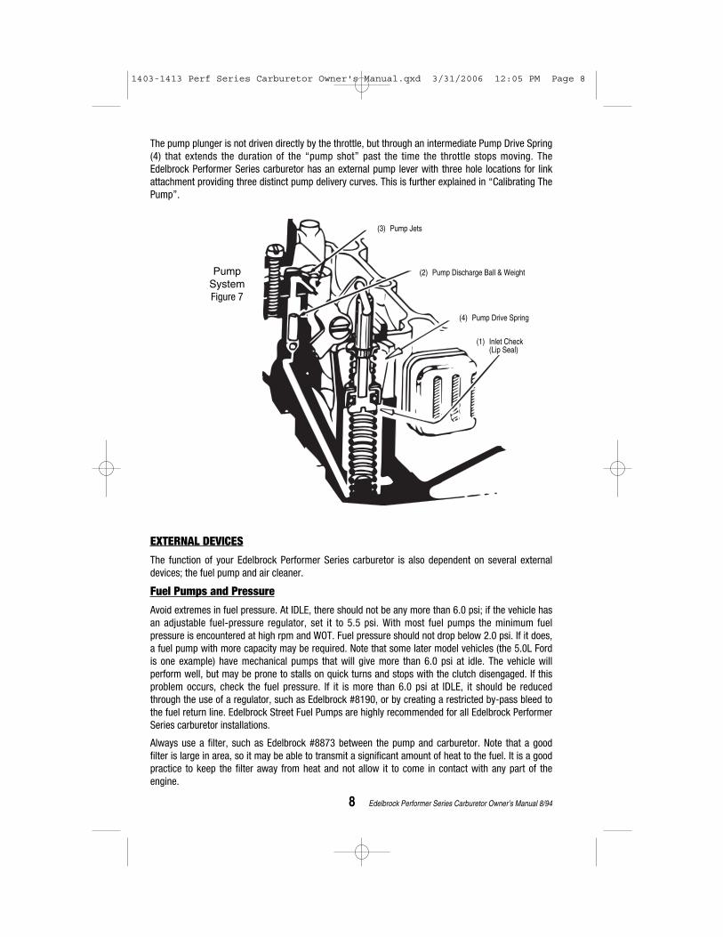
When the throttle is opened rapidly, the air flow through the engine will increase immediately. Thefuel, since it is much heavier than the air, will “lag” behind. This contributes to a temporary lean A/Fcondition. Regardless of cause, a solution is to temporarily enrichen the A/F Ratio by mechanicallypumping a small quantity of fuel into the throat of the carburetor (Figure 7). The Edelbrock carburetorhas a piston that draws fuel into the pump cavity past the plunger lip-seal when the throttle is closing(1). Upon opening, the lip-seal seats, allowing the plunger to force the fuel through another one-wayvalve, the Pump Discharge Ball and Weight (2), and the Pump Jets (3) into the primary throats.
Secondary Auxiliary SystemFigure 6
(3) SecondaryMain Jet
(2) DischargeNozzle
(4) AuxiliaryFuel Tube
(5) Air-Bleed (some PNs)
(1) Air Valve
1403-1413 Perf Series Carburetor Owner's Manual.qxd 3/31/2006 12:05 PM Page 7
8 Edelbrock Performer Series Carburetor Owner’s Manual 8/94
EXTERNAL DEVICES
The function of your Edelbrock Performer Series carburetor is also dependent on several externaldevices; the fuel pump and air cleaner.
Fuel Pumps and Pressure
Avoid extremes in fuel pressure. At IDLE, there should not be any more than 6.0 psi; if the vehicle hasan adjustable fuel-pressure regulator, set it to 5.5 psi. With most fuel pumps the minimum fuelpressure is encountered at high rpm and WOT. Fuel pressure should not drop below 2.0 psi. If it does,a fuel pump with more capacity may be required. Note that some later model vehicles (the 5.0L Fordis one example) have mechanical pumps that will give more than 6.0 psi at idle. The vehicle willperform well, but may be prone to stalls on quick turns and stops with the clutch disengaged. If thisproblem occurs, check the fuel pressure. If it is more than 6.0 psi at IDLE, it should be reducedthrough the use of a regulator, such as Edelbrock #8190, or by creating a restricted by-pass bleed tothe fuel return line. Edelbrock Street Fuel Pumps are highly recommended for all Edelbrock PerformerSeries carburetor installations.
Always use a filter, such as Edelbrock #8873 between the pump and carburetor. Note that a goodfilter is large in area, so it may be able to transmit a significant amount of heat to the fuel. It is a goodpractice to keep the filter away from heat and not allow it to come in contact with any part of theengine.
The pump plunger is not driven directly by the throttle, but through an intermediate Pump Drive Spring(4) that extends the duration of the “pump shot” past the time the throttle stops moving. TheEdelbrock Performer Series carburetor has an external pump lever with three hole locations for linkattachment providing three distinct pump delivery curves. This is further explained in “Calibrating ThePump”.
PumpSystemFigure 7
(3) Pump Jets
(2) Pump Discharge Ball & Weight
(4) Pump Drive Spring
(1) Inlet Check (Lip Seal)
1403-1413 Perf Series Carburetor Owner's Manual.qxd 3/31/2006 12:05 PM Page 8

9 Edelbrock Performer Series Carburetor Owner’s Manual 8/94
Air Cleaners
Your Edelbrock carburetor was originally calibrated with a low restriction open element air cleanerconfiguration; a 14”x3” Edelbrock Signature Series unit. It was also evaluated for proper metering andvehicle performance using a variety of other air cleaner designs and will perform as intended withnearly any reasonable air cleaner design. While the Edelbrock Performer Series carburetor does notexhibit excessive sensitivity to the air cleaner, there are several guidelines you should follow whenselecting an air cleaner:
• Running without an air cleaner is strongly discouraged for a street-driven vehicle. Dirt andvarnish will accumulate in critical bleeds and upset the fuel metering. Dirt and debris may easilyget into the fuel bowl through the bowl vents or larger bleeds and cause a multitude ofproblems.
• Any calibration testing should be performed with the air cleaner in place. Depending upon the aircleaner used, the metering typically will be leaner with the air cleaner in place.
— A large 14”x3” open element air cleaner, such as Edelbrock Elite Series, Signature Series andPro-Flo air cleaners, offers almost no resistance to air flow. Flow bench results show virtually noreduction in air flow. Also, this design should cause no change to the fuel metering.
— A 10”x2” open element design will result in some definite air flow restriction but little change tothe fuel metering.
— Elements smaller than 10”x2” are more restrictive and have the most effect upon metering. The fuel metering at WOT will be shifted LEANER, especially at higher rpm ranges.
• If you have a dual-purpose vehicle that is sometimes used in competition without an air cleaner,it may be necessary to have two separate calibrations. If you are running a smaller air cleanerand have optimized the WOT with it in place, do not be surprised to find that the metering shiftsRICHER when the air cleaner is removed. This may require you to calibrate the WOT with leanerJets and Rods at the drag strip.
• DO NOT allow the vehicle air-stream to blow across the top of the carburetor(s) such as on anopen-bodied car or full-bodied vehicle with a tunnel-ram manifold. The flow of air across thecarburetor will result in an upset to the fuel metering that cannot be accommodated byrecalibration since the change to the A/F Ratio will be different for every vehicle speed.
SECTION 2 : TUNING PROCEDURE
Before proceeding please ensure you have installed your Edelbrock Performer SeriesCarburetor according to the Carburetor Installation Instructions included with the carburetor
REVISING THE CALIBRATION
The Edelbrock Performer Series Carburetor is designed to allow quick and easy changes to themetering. Virtually any change imaginable can be performed without removing the carburetor fromthe manifold, and the most common changes may be performed in less than five minutes withoutremoval of the airhorn (bowl cover).
1403-1413 Perf Series Carburetor Owner's Manual.qxd 3/31/2006 12:05 PM Page 9

10 Edelbrock Performer Series Carburetor Owner’s Manual 9/01
To help you calibrate your carburetor, a CALIBRATION REFERENCE CHART has been designed for eachmodel of the Edelbrock Performer Series carburetor. These charts (pages 18—31) each consist of twosections: A Calibration Table and a Rod/Jet Reference Chart.
After reading the Calibration procedures, the next step in calibrating your carburetor is to look at theCalibration Table for your model carburetor. Determine if you would like to go richer or leaner in theCruise Mode and do the same for the Power Mode. Select the number that is closest to intersection ofyour Cruise and Power Mode selections. This is your calibration reference number. Now refer to theRod/Jet Reference Chart that appears on the opposing page. Locate your calibration referencenumber to determine the rod/jet combination for your application.
For example, you have a 1405 Edelbrock Performer Series carburetor. You have determined (byreading the rest of the manual) you would like to go 1 stage lean in the Cruise Mode and 2 stages leanin the Power Mode. The intersection of these two lines lies on the number 21. This is your calibrationreference number. Now look below the Calibration Table to the Rod/Jet Reference Chart. Find thenumber 21 under the REF# column. The jets you should use are .098 and the rods are .070 x .052.
Located at the very bottom of each Calibration Reference Chart is a guide for changing yourSecondary Metering. This will be useful when calibrating the wide-open-throttle (WOT).
Before you attempt to establish a new calibration, be sure that the engine is in a sound state of tune.All ignition items must be in proper working order, including reasonably fresh plugs of the correct heatrange. Timing should be properly set and the air filter element and fuel filter should be clean.
Proper fuel pressure should be verified and cracked or brittle vacuum lines should be eliminated. Many so-called “carburetor calibration” problems have been traced to another part of theengine system that was not functioning properly.
CAUTION: Be alert to carburetor flooding when fuel is first applied. Flooding can be caused by dirt,small particles of hose cuttings, floats and inlet needles which have settled during shipping, orby other conditions as discussed below. Each Edelbrock Performer Series carburetor is flowtested in the factory for both air and liquid flow so flooding is rare. However, for safety sakeplease observe this caution. When the fuel pump is turned on or when the engine is first started,watch closely for signs of flooding. If flooding is apparent, tap the body of the carburetor lightlywith a rawhide mallet or the wooden handle of a small hammer. If flooding continues, pinch thefuel line hose to shut off flow, run the engine to clear the carburetor, and let the fuel line flowagain. If flooding continues, pinch the fuel line hose to shut off flow, run the engine to clear thecarburetor, and let the fuel line flow again. If flooding still continues, stop the engine. Clean upany raw gasoline and refer to the “Trouble Shooting” section of the Owner’s Manual.
Parts and Equipment —Aside from ordinary hand tools, the following items are recommended.
• Edelbrock Performer Series Carburetor Jet Set - Contains selections of Main Jets, Metering Rods, and Springs.
• Tachometer - If the vehicle is not equipped with a tach, the dwell meter style tach will be adequate. If neither is available, you will be able to use the speedometer in place of the tach for some of the procedures, but it will not be as convenient.
• Vacuum Gauge - Should be hooked up to read engine’s intake manifold vacuum. Without a vacuum gauge, some of the calibration procedures will be more difficult.
1403-1413 Perf Series Carburetor Owner's Manual.qxd 3/31/2006 12:05 PM Page 10

11 Edelbrock Performer Series Carburetor Owner’s Manual 9/01
Changing Components
Metering Rod and Step-Up Spring changes can typically be made in less than five minutes andwithout removing the carburetor. First, loosen the Step-Up Piston Cover Screws (See pg. 32) and twistthe Step-Up Piston Cover Plates to the side. The Metering Rods and Step-Up Springs can now beremoved and replaced if necessary. Be sure to replace the Step-Up Piston Cover Plate and tighten theStep-Up Piston Cover Screw when finished. CAUTION: Do not overtighten the Step-Up PistonCover Screws! They should only be tightened to 12 to 17 inch/pounds. Excessive torque willweaken or snap off the screw heads. If this happens, they may fall into the carb causing seriousengine damage. If an inch/pound torque wrench is not available, snug the screw until it just touchesthe plate, then tighten 1/16th turn more.
To replace the Primary or Secondary Metering Jets, first, remove the Metering Rods and Step-UpSprings as outlined in the preceding paragraph. Next, disconnect the Choke Cam Connector Rod,Pump Connector Rod, and Choke Connector Rod (when applicable). Finally, remove the 8 AirhornAttaching Screws and remove the Airhorn from the carburetor body. A standard screwdriver can nowbe used to remove the appropriate Metering Jets. Once desired Metering Jets have been installed thecarb may be reassembled by reversing this procedure.
IDLE MIXTURE
The Edelbrock Performer Series carburetor has conventional Idle Mixture Screws (IMS) that provide aleaner A/F when turned clockwise and richer A/F when turned counter clockwise. The idle air flow iscontrolled by a conventional screw that opens the Primary Throttles. The following procedure shouldbe used to set the idle mixture and speeds.
1. Fully warm engine and ensure choke is fully open.
2. Air cleaner in place.
3. Set desired speed with the air screw.
4. Adjust the IMS on ONE side to get the maximum possible RPM. Do not go rich beyond the maximum speed point.
5. If the above changed the idle speed more than 40 RPM, then readjust the speed.
6. Adjust the side OPPOSITE of that in Step 4 to get maximum RPM.
7. Reset the speed.
8. Carefully trim each IMS to again get the maximum idle RPM.
9. Go leaner just enough to get a 20 RPM drop in speed.
10. Reset the speed to the desired RPM.
11. This is a Lean-Best Idle Set. Setting richer than this will not improve idle quality or performance, but could tend to foul plugs.
Winter Fuel Idle SetsDuring the winter months (in most parts of the country) the local fuel will be a “winter” blend that isvery volatile, as an assist to cold-engine starting and driveability during warm-up. However, the highvolatility has the disadvantage of allowing excessive vaporization of the fuel if the vehicle is operatedin a heated area such as a garage. This can result in problems in the idle-set procedures since thecarburetor’s internal vents will allow this excess vapor to be drawn into the throats and enrichen themixture. The idle will be erratic and not seem to be able to hold a set. To resolve this type of problem,it is advisable to perform the final settings outdoors after the vehicle has been stabilized with a driveof several miles.
1403-1413 Perf Series Carburetor Owner's Manual.qxd 3/31/2006 12:05 PM Page 11

12 Edelbrock Performer Series Carburetor Owner’s Manual 8/94
Long Duration Camshaft
If the engine has a fairly radical camshaft it may require an excessive amount of throttle opening for idle and/or have low idle vacuum levels. Either condition can lead to poor levels ofadjustability and erratic idles.
• Another fix for the above condition is to run as much spark advance as possible at idle. If thedistributor is fitted with a vacuum advance unit, connect it directly to manifold vacuum. If youare not able to employ vacuum advance for some reason, then the mechanical curve shouldhave a low limit, which will allow you to use plenty of initial spark advance.
• Measure the manifold vacuum at idle. If it is below 7” Hg, there is a good chance that theMetering Rods are in the up (rich) position. When combined with a high idle air rate this cancause the Nozzles to discharge fuel at idle. Use a weaker Step-Up Spring (see section on Step-Up calibration) to keep the Rods down at idle. With some cams, a stiffer spring (pink or silver) isnecessary. Experimentation is the best way to determine which is best for your application.
CALIBRATING THE WIDE-OPEN-THROTTLE (WOT)
The best place to perform your WOT calibration is on a chassis dyno. If one is not available thenconsider a safe, legal driving space, such as a drag strip where you are given E.T. and MPH data.
1. Select an RPM Range to use in evaluating the WOT power. As a rule, use the highest 50percent of the real power band. If your engine makes good power up to 5000 RPM, then2500-5000 is a good range. If peak power is at 6500, then 3500-6500 would be a goodpick. Be sure not to select RPMs that are higher than the engine’s useful power band.
2. Accelerate at WOT from 1000 RPM below the range you have elected to a few hundred overthe range. Time the acceleration with a stop-watch. Be sure to time only the interval whilethe engine is sweeping through the selected range. Make enough timed accelerations to geta good average that is not affected by wind or grade.
3. Refer to the Calibration Reference Chart for your model. Find the richest Power Mode(Primary Metering) change you can make without changing a Jet — a Rod change only.This will probably be 2 stages (8%) rich.
4. Change to the indicated Rods. Perform timed acceleration #2. Compare the times. Do not besurprised if there is no difference.
5. Compare the results of timed acceleration #2 to the base calibration and refer to thefollowing section that best describes your situation:
Case 1: Faster than base calibration
Change Secondaries 2 stages richer and perform acceleration test #3.
• If test #3 is the same as #2, you’re done.
• If test #3 is slower than #2, change to 1 stage rich for the Primary and Secondary and you’redone.
• If test #3 is still faster than #2, go to 3 stages rich Primary and Secondary and keep going richeruntil there is no change (or slower) in the times. Stay at the first “no change” level, so that youstay with the richer of any two levels of calibration that have the same power.
1403-1413 Perf Series Carburetor Owner's Manual.qxd 3/31/2006 12:05 PM Page 12
13 Edelbrock Performer Series Carburetor Owner’s Manual 8/94
Case 2: Slower than base calibration
Go to 1 stage lean Primaries and 1 lean Secondaries and perform acceleration test #3.
• If test #3 is the same as base calibration, go back to the base calibration.
• If test #3 is faster than base calibration, go to 2 stages lean on both the Primaries and theSecondaries. Keep going in the lean direction until there is no change or slower then back up 1stage richer, so that you stay with the richer of any two levels of calibration that have the samepower.
Case 3: Same as base calibration
Do not be surprised. Change back to base calibration.
CALIBRATING THE PART-THROTTLE
The Metering Rod feature used in the Edelbrock Performer allows easy calibration of the part-throttlewithout change to the WOT metering.
• Cruise Mode: The power output is low, as in a steady cruise light acceleration. Manifold Vacuumis high and the Metering Rods are down in the lean position.
• Power Mode: The power output is high, as in a heavy but not wide-open acceleration. ManifoldVacuum is low and the Rods are up in the rich position.
As explained in the “Theory of Operation,” the Step-Up function modulates the Rods between theCruise and Power positions.
The part-throttle calibration is more “individualized” than is the Wide-Open-Throttle (WOT). It is notmeasured by absolute numbers, but reflects the driver’s feel for a particular combination.
Carefully evaluate the driveability with the carburetor at the calibration level determined from the WOTexercise. Drive at a variety of engine speeds and throttle openings looking for any flat spots orlean/surge conditions.
Cruise Mode
If there are any surge or flat spot conditions in the steady speed cruises or light accelerations, a leancondition probably exists. Consult the Calibration Reference Chart and change to 1 stage rich in theCruise Mode. If it gets better, but not completely fixed, keep going in the rich direction. TheCalibration Reference Chart will give you Rod and Jet combinations that are directionally correct oryou may choose your own.
If the light throttle is satisfactory, trying going 1 stage lean in the Cruise Mode. If there are still noproblems with surge or other indications of lean metering, do not hesitate to go to 2 stages lean in theCruise Mode. A lean Cruise Mode has advantages in fuel economy and keeping the plugs clean. Keepgoing until you begin to notice driveability problems and then back up 1 stage.
Power Mode
Accelerations at part-throttle with low manifold vacuum (less than about 5” Hg on a vacuum gauge)are metered by the Power Mode. Avoid calibrating this portion of the engine’s operating range too lean as spark knock (detonation) and piston/valve burning can occur. If this modehas any lean driveability symptoms (surge or flat spots), it is too lean and should be recalibrated atleast 1 stage richer.
1403-1413 Perf Series Carburetor Owner's Manual.qxd 3/31/2006 12:05 PM Page 13

14 Edelbrock Performer Series Carburetor Owner’s Manual 1/01
CALIBRATING THE POWER MODE STAGING
The Step-Up function, which moves the Metering Rod to the Power Mode, is controlled by the Step-UpSpring. The base calibration has a spring which “stages” rich at 5” Hg.
If your vehicle has a mid-throttle driveability problem that is encountered as the throttle is graduallyopened, but then goes away upon further opening, it may be possible to eliminate the lean spot byusing a stronger Step-Up Spring. The available Step-Up Springs are listed in the following chart alongwith their respective “staging” point. It is best to select a new spring on the basis of vacuumreadings, but in the absence of a gauge, try the strongest spring (highest vacuum rating) to see if theproblem goes away. If the drive problem is cured by the strong spring, try the next weakest spring aswell. If the strong one does not help, then the calibration problem is related to the A/F metering stageof either the Cruise or Power Modes. Use the Calibration Reference Chart to help select anothercombination.
CALIBRATING THE PUMP
If you encounter any hesitations or stumbles that do not seem to be related to the basic metering orhave not responded to changes in the basic metering, move the pump drive link to one of the holescloser to the carburetor body. This will increase the stroke length of the plunger and result in morepump delivery.
FLOAT ADJUSTMENT
To properly adjust the floats in the EPS carburetor, two procedures must be followed. First, invert theairhorn cover (Figure 8) holding the airhorn gasket in place. There should be 7/16” between theairhorn gasket and the top of the outer end of the float. To adjust the float level, bend the float leveruntil the recommended level is attained. DO NOT press the needle into the seat when adjusting thefloat lever. Next, you should check the float drop (Figure 9). Hold the airhorn upright and let the floatshang down. There should be 15/16" to 1" between the airhorn gasket and the top of the outer end ofthe float. To adjust the float drop, bend the tab on the back until the recommended float drop isattained. For the off-road float adjustment, see page 16.
CHOKE ADJUSTMENT
To adjust the choke piston linkage (Figure 10) open the choke valve and insert a .026” wire, with a 90degree bend 1/8” from the end, between the top of the slot in the choke piston cylinder and thebottom of the slot in the piston. Hold the wire in position and close the choke valve by pressing onpiston lever A until resistance is felt. The dimension C should be .100” between the top edge of thechoke valve and the air horn. To adjust, bend rod B.
To adjust the fast idle linkage (Figure 11) place the fast idle screw A between the two notches on thecam. Close the choke valve as far as possible without forcing it. The dimension C should be 3/64”between the choke valve and the air horn. To adjust bend rod D.
Fast idle may be adjusted to manufacturers specifications (usually 1500 rpm) during normal chokecold operation. The fast idle screw A can be adjusted with engine off and throttle held open to allowscrew head access. Recheck fast idle speed after each adjustment.
Spring Color Blue Yellow Orange Pink Plain
Staging Vacuum 3" 4" 5" 7" 8"("Hg)
A complete set of these springs is available separately as Edelbrock part #1464.
1403-1413 Perf Series Carburetor Owner's Manual.qxd 3/31/2006 12:05 PM Page 14

15 Edelbrock Performer Series Carburetor Owner’s Manual Rev 9/01
Float Drop (15/16" to 1")Figure 9
Float Level (7/16")Figure 8
Fast idle linkageFigure 11
Choke piston linkageFigure 10
BEND HERE
TAB
C (.100")
C (3/64")
A
A
B
D
.026 Wire
Slot Piston Cylinder
7/16” Drill bit
1403-1413 Perf Series Carburetor Owner's Manual.qxd 3/31/2006 12:05 PM Page 15

16 Edelbrock Performer Series Carburetor Owner’s Manual Rev 1/01
* = Carburetor is certified to meet U.S. Coast Guard Requirements
The length of time during which the choke will stay closed is determined by the position of the chokecap. As the choke cap is turned clockwise the choke will stay closed longer. To properly set the choketurn the choke cap to the leanest notch on the choke housing, loosen the choke housing retainingscrews, and run the engine until normal operating temperature is reached. With the engine running,slowly turn the choke cap clockwise until the choke valve begins to close. Now turn the chokehousing one notch counterclockwise (LEAN) and tighten the choke housing retaining screws. Periodicreadjustment of the choke will be required as the temperature changes throughout the year. Aftereach adjustment verify that the choke valve opens fully after the engine is warm.
SPECIAL CALIBRATIONS
The preceding calibrations and adjustments apply to carburetors used in general street applications.In the following extreme instances, special calibration procedures may need to be followed.
Off-Road
Although the Edelbrock Performer Series carburetor was not calibrated with hill climbing and otherextreme off-road operation in mind, it can be made to perform superbly by substituting Edelbrock#1465 spring loaded needle and seat for the original needle and seat. The spring loaded needle andseat act like a shock absorber, reducing the possibility of flooding during off-road operation. Afterinstallation of the new needle and seat you must reset the float level to 7/16" and drop the float dropto 15/16 to 1" as outlined in “FLOAT ADJUSTMENT”.
High Fuel Flow
When evidence of fuel starvation exists, first ensure that proper pressure (4-5 psi minimum) ismaintained at WOT. If proper fuel pressure is supplied and fuel starvation still exists, it may benecessary to change the needle and seat to a larger size (#1466). Do not make this change unlessabsolutely required, as the smaller inlet is preferred for proper fuel control under most conditions.
High Altitude
Altitude has a direct effect on the operation of most carburetors. As the altitude increases, the airbecomes less dense so a carburetor, originally calibrated at low altitude, delivers too much fuel andthe engine runs richer. If the preceding tuning procedure is performed on an Edelbrock PerformerSeries carburetor, a proper high altitude calibration will result. If the vehicle was calibrated at lower
Carburetor CFM Main Main Metering Step-Up Needle FloatPart No. Jet Jet Rod Spring & Seat Height
Primary Secondary (Primary only)1404 500 .086" .095" .065" x .052" orange (5") .0935" 7/16" 1405 600 .100" .095" .070" x .047" orange (5") .0935" 7/16"1406 600 .098" .095" .075" x .047" yellow (4") .0935" 7/16"1407 750 .113" .107" .071" x .047" orange (5") .0935" 7/16"1409* 600 .098" .101" .068" x .047" orange (5") .0935" 7/16"1410* 750 .113" .107" .071" x .047" orange (5") .0935" 7/16"1411 750 .110" .107" .075" x .047" orange (5") .0935" 7/16"1412 800 .113" .101" .071" x .047" orange (5") .0935" 7/16"1413 800 .113" .101" .071" x .047" orange (5") .0935" 7/16"
Carburetor Specifications - All Models
1403-1413 Perf Series Carburetor Owner's Manual.qxd 3/31/2006 12:05 PM Page 16

17 Edelbrock Performer Series Carburetor Owner’s Manual 9/01
altitude, however, and is to be driven at high altitude temporarily, it is not necessary to repeat thecomplete calibration procedure. Instead, use the rule of: “2% leaner per 1500 feet” and theCalibration Reference Chart for your model carburetor. For example, with a #1405 at baselinecalibration (location #1 on the chart) and intended operation at 6000 ft. altitude, you would want 6000divided by 1500 x 2% = 8% leaner calibration. That would be location #24 on the chart which wouldrequire only a rod and jet change.
Blended Fuels
Typically, two types of blended fuels are available: Gasohol and gasahol. Gasohol is a blend of notmore than 10% ethanol and gasoline. As long as there is no more than 10% ethanol mixed with thegasoline you carburetor will function properly. As the percentage of ethanol climbs above10%, aricher A/F ratio will be required. Also, because gasohol is more volatile than gasoline, hard hot startingand poor hot weather driveability may result.
Gasahol can be a blend of either ethanol, methanol or other alcohol with gasoline. Methanol blendedfuel should not be used in your Edelbrock Performer Series carburetor as it will cause corrosion of thefuel system components. It can also cause rapid failure of seals, gaskets, diaphragms and pumpplungers.
Always check to see if you are using a blended fuel. Although the pump may not indicate the fuel isblended, it is always advisable to verify the type of fuel the station carries.
Blown Engines
Two model #1405 carburetors should be used on engines with positive displacement superchargers,such as GMC 6-71 blowers or equivalent. The following calibration changes make an excellentstarting point: Primary Jets - .101" (#1429); Secondary Jets - .101” (#1429); Metering Rods - .070" x.042" (#1450); Step-up Piston Springs - 5" (orange, stock); Needle & Seat assemblies - .110"(#1466).
This calibration has been tested on engines ranging in size from 350 c.i.d. Chevys to 440 c.i.d.Chryslers with good results.
Float Pump Drive Accelerator Venturi Venturi Throttle Bore Throttle BoreDrop Link Pump Diameter Diameter Diameter Diameter(±1/4") Location Nozzle Diameter Primaries Secondaries Primaries Secondary1-1/4" middle hole .028" 1-3/16" 1-9/16" 1-7/16" 1-11/16"1-1/4" middle hole .028" 1-3/16 " 1-9/16" 1-7/16" 1-11/16"1-1/4" middle hole .031" 1-3/16 " 1-9/16" 1-7/16" 1-11/16"1-1/4" top hole .035" 1-7/16 " 1-9/16" 1-11/16" 1-11/16"1-1/4" middle hole .028" 1-3/16 " 1-9/16" 1-7/16" 1-11/16"1-1/4" top hole .035" 1-7/16 " 1-9/16" 1-11/16" 1-11/16"1-1/4" top hole .035" 1-7/16 " 1-9/16" 1-11/16" 1-11/16"1-1/4" top hole .035" 1-17/32 " 1-5/8" 1-3/4" 1-3/4"1-1/4" top hole .035" 1-17/32 " 1-5/8" 1-3/4" 1-3/4"
Carburetor Specifications (continued)
1403-1413 Perf Series Carburetor Owner's Manual.qxd 3/31/2006 12:05 PM Page 17

18 Edelbrock Performer Series Carburetor Owner’s Manual 12/01
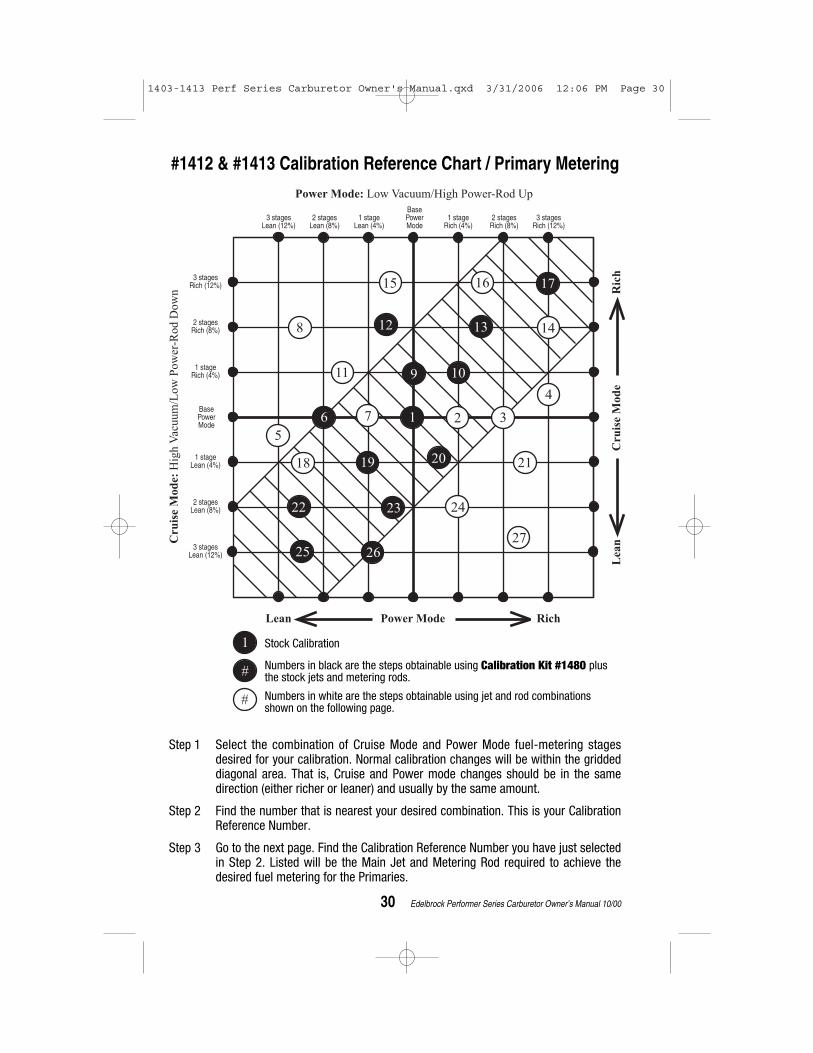
Step 1 Select the combination of Cruise Mode and Power Mode fuel-metering stagesdesired for your calibration. Normal calibration changes will be within the griddeddiagonal area. That is, Cruise and Power mode changes should be in the samedirection (either richer or leaner) and usually by the same amount.
Step 2 Find the number that is nearest your desired combination. This is your CalibrationReference Number.
Step 3 Go to the next page. Find the Calibration Reference Number you have just selectedin Step 2. Listed will be the Main Jet and Metering Rod required to achieve thedesired fuel metering for the Primaries.
1 2
25
Power Mode: Low Vacuum/High Power-Rod Up
3 stages Lean (12%)
2 stages Lean (8%)
1 stage Lean (4%)
Base Power Mode
1 stage Rich (4%)
2 stages Rich (8%)
3 stages Rich (12%)
3 stages Rich (12%)
2 stages Rich (8%)
1 stage Rich (4%)
1 stage Lean (4%)
2 stages Lean (8%)
3 stages Lean (12%)
Base Power Mode
Cru
ise M
od
e:
Hig
h V
acuum
/Low
Pow
er-R
od D
ow
n
Lean
Cru
ise M
od
eR
ich
Lean Power Mode Rich
34
56
7 8 9
1012
13 14 15
16
11
1718 19
20
2122
2324
2627
1
#
#
Stock Calibration
Numbers in black are the steps obtainable using Calibration Kit #1486 plusthe stock jets and metering rods.
Numbers in white are the steps obtainable using jet and rod combinationsshown on the following page.
#1403/ #1404 Calibration Reference Chart / Primary Metering
1403-1413 Perf Series Carburetor Owner's Manual.qxd 3/31/2006 12:05 PM Page 18

19 Edelbrock Performer Series Carburetor Owner’s Manual 12/01
3 Stages 2 Stages 1 Stage SECONDARY 1 Stage 2 Stages 3 StagesLean (12%) Lean (8%) Lean (4%) Stock Calibration Rich (4%) Rich (8%) Rich (12%)
JET #1423 JET #1424 JET #1425 JET #1426 JET #1427 JET #1429 JET #1430(.086) (.089) (.092) (.095) (.098) (.101) (.104)
Model #1403/#1404Rod/Jet Reference Chart
REF # MAIN JET METERING ROD CHANGE FROM BASE
1 1423 (.086) 1460 (065 x 052) none - stock calibration2 1423 (.086) 1445 (065 x 047) Rod3 1423 (.086) 1444 (065 x 037) Rod4 1423 (.086) 1461 (065 x 057) Rod 5 1422 (.083) 1441 (062 x 052) Rod & Jet6 1423 (.086) 1463 (067 x 055) Rod7 1423 (.086) 1448 (068 x 052) Rod 8 1423 (.086) 1447 (068 x 047) Rod9 1423 (.086) 1446 (068 x 042) Rod
10 1422 (.083) 1463 (067 x 055) Rod & Jet11 1422 (.083) 1460 (065 x 052) Jet12 1422 (.083) 1462 (067 x 049) Rod & Jet13 1423 (.086) 1452 (070 x 052) Rod 14 1423 (.086) 1451 (070 x 047) Rod 15 1423 (.086) 1450 (070 x 042) Rod 16 1422 (.083) 1438 (058 x 052) Rod & Jet17 1422 (.083) 1437 (057 x 049) Rod & Jet18 1423 (.086) 1441 (062 x 052) Rod19 1423 (.086) 1443 (063 x 047) Rod 20 1423 (.086) 1442 (063 x 037) Rod 21 1424 (.089) 1445 (065 x 047) Rod & Jet22 1424 (.089) 1460 (065 x 052) Jet23 1423 (.086) 1439 (060 x 052) Rod24 1423 (.086) 1440 (060 x 057) Rod 25 1422 (.083) 1436 (055 x 055) Rod & Jet26 1424 (.089) 1441 (062 x 052) Rod & Jet27 1424 (.089) 1443 (063 x 047) Rod & Jet
Main Jet I.D.—All Edelbrock jets have “120-”prefix. The last three digits minus 300 = actual jet size.Examples: 120-386 = .086" jet (Edelbrock p/n 1423).
120-401 = .101" jet (Edelbrock p/n 1429).
Secondary MeteringThe factory calibration jet is shown in the center column. For leaner or richer calibrationuse the jet # indicated in the appropriate column.
1403-1413 Perf Series Carburetor Owner's Manual.qxd 3/31/2006 12:05 PM Page 19

20 Edelbrock Performer Series Carburetor Owner’s Manual 8/94
Step 1 Select the combination of Cruise Mode and Power Mode fuel-metering stagesdesired for your calibration. Normal calibration changes will be within the griddeddiagonal area. That is, Cruise and Power mode changes should be in the samedirection (either richer or leaner) and usually by the same amount.
Step 2 Find the number that is nearest your desired combination. This is your CalibrationReference Number.
Step 3 Go to the next page. Find the Calibration Reference Number you have just selectedin Step 2. Listed will be the Main Jet and Metering Rod required to achieve thedesired fuel metering for the Primaries.
1 2
Power Mode: Low Vacuum/High Power-Rod Up
3 stages Lean (12%)
2 stages Lean (8%)
1 stage Lean (4%)
Base Power Mode
1 stage Rich (4%)
2 stages Rich (8%)
3 stages Rich (12%)
3 stages Rich (12%)
2 stages Rich (8%)
1 stage Rich (4%)
1 stage Lean (4%)
2 stages Lean (8%)
3 stages Lean (12%)
Base Power Mode
Cru
ise M
od
e:
Hig
h V
acuum
/Low
Pow
er-R
od D
ow
n
Lean
Cru
ise M
od
eR
ich
Lean Power Mode Rich
3
4
5 6
10
1216 17
20
22 23
7 8 9
1113 14 15
18 19
21
24 25 26
27 28 29
30
1
#
#
Stock Calibration
Numbers in black are the steps obtainable using Calibration Kit #1479 plusthe stock jets and metering rods.
Numbers in white are the steps obtainable using jet and rod combinationsshown on the following page.
#1405 Calibration Reference Chart / Primary Metering
1403-1413 Perf Series Carburetor Owner's Manual.qxd 3/31/2006 12:05 PM Page 20

21 Edelbrock Performer Series Carburetor Owner’s Manual 8/94
Model #1405Rod/Jet Reference Chart
REF # MAIN JET METERING ROD CHANGE FROM BASE1 1428 (.100) 1451 (070 x 047)* none - stock calibration
*Some Have ID #6952 1428 (.100) 1450 (070 x 042) Rod3 1428 (.100) 1449 (070 x 037) Rod4 1430 (.104) 1458 (075 x 037) Rod & Jet5 1427 (.098) 1448 (068 x 052) Rod & Jet6 1428 (.100) 1452 (070 x 052) Rod7 1427 (.098) 1445 (065 x 047) Rod & Jet8 1428 (.100) 1448 (068 x 052) Rod9 1428 (.100) 1446 (068 x 042) Rod
10 1430 (.104) 1459 (075 x 047) Rod & Jet11 1430 (.104) 1455 (073 x 042) Rod & Jet12 1427 (.098) 1441 (062 x 052) Rod & Jet13 1429 (.101) 1448 (068 x 052) Rod & Jet14 1430 (.104) 1457 (073 x 052) Rod & Jet15 1430 (.104) 1456 (073 x 047) Rod & Jet16 1428 (.100) 1445 (065 x 047) Rod 17 1430 (.104) 1452 (070 x 052) Rod & Jet18 1430 (.104) 1451 (070 x 047)* Jet
*Some Have ID #69519 1430 (.104) 1450 (070 x 042) Rod & Jet20 1426 (.095) 1445 (065 x 047) Rod & Jet21 1427 (.098) 1452 (070 x 052) Rod & Jet22 1428 (.100) 1457 (073 x 052) Rod23 1428 (.100) 1455 (073 x 042) Rod24 1427 (.098) 1457 (073 x 052) Rod & Jet25 1428 (.100) 1459 (075 x 047) Rod26 1427 (.098) 1449 (070 x 037) Rod & Jet27 1426 (.095) 1446 (068 x 042) Rod & Jet28 1427 (.098) 1456 (073 x 047) Rod & Jet29 1427 (.098) 1455 (073 x 042) Rod & Jet30 1429 (.101) 1458 (075 x 037) Rod & Jet
3 Stages 2 Stages 1 Stage SECONDARY 1 Stage 2 Stages 3 StagesLean (12%) Lean (8%) Lean (4%) Stock Calibration Rich (4%) Rich (8%) Rich (12%)
JET #1423 JET #1424 JET #1425 JET #1426 JET #1427 JET #1429 JET #1430(.086) (.089) (.092) (.095) (.098) (.101) (.104)
Main Jet I.D.—All Edelbrock jets have “120-”prefix. The last three digits minus 300 = actual jet size.Examples: 120-398 = .098" jet (Edelbrock p/n 1427).
120-400 = .100" jet (Edelbrock p/n 1428).
Secondary MeteringThe factory calibration jet is shown in the center column. For leaner or richer calibrationuse the jet # indicated in the appropriate column.
1403-1413 Perf Series Carburetor Owner's Manual.qxd 3/31/2006 12:05 PM Page 21

22 Edelbrock Performer Series Carburetor Owner’s Manual 1/01
Step 1 Select the combination of Cruise Mode and Power Mode fuel-metering stagesdesired for your calibration. Normal calibration changes will be within the griddeddiagonal area. That is, Cruise and Power mode changes should be in the samedirection (either richer or leaner) and usually by the same amount.
Step 2 Find the number that is nearest your desired combination. This is your CalibrationReference Number.
Step 3 Go to the next page. Find the Calibration Reference Number you have just selectedin Step 2. Listed will be the Main Jet and Metering Rod required to achieve thedesired fuel metering for the Primaries.
1 2
25
Power Mode: Low Vacuum/High Power-Rod Up
3 stages Lean (12%)
2 stages Lean (8%)
1 stage Lean (4%)
Base Power Mode
1 stage Rich (4%)
2 stages Rich (8%)
3 stages Rich (12%)
3 stages Rich (12%)
2 stages Rich (8%)
1 stage Rich (4%)
1 stage Lean (4%)
2 stages Lean (8%)
3 stages Lean (12%)
Base Power Mode
Cru
ise M
od
e:
Hig
h V
acuum
/Low
Pow
er-R
od D
ow
n
Lean
Cru
ise M
od
eR
ich
Lean Power Mode Rich
34
7 9
13 14
15
16
18
20
21
5
6
8
10
11 12
17
19
22
23
24
1
#
#
Stock Calibration
Numbers in black are the steps obtainable using Calibration Kit #1487 plusthe stock jets and metering rods.
Numbers in white are the steps obtainable using jet and rod combinationsshown on the following page.
#1406 Calibration Reference Chart / Primary Metering
2
1
1403-1413 Perf Series Carburetor Owner's Manual.qxd 3/31/2006 12:06 PM Page 22

23 Edelbrock Performer Series Carburetor Owner’s Manual 8/94
Model #1406Rod/Jet Reference Chart
REF # MAIN JET METERING ROD CHANGE FROM BASE
1 1427 (.098) 1459 (075 x 047) none - stock calibration2 1426 (.095) 1449 (070 x 037) Rod & Jet3 1427 (.098) 1458 (075 x 037) Rod4 1425 (.092) 1446 (068 x 042) Rod & Jet5 1426 (.095) 1453 (071 x 047) Rod & Jet6 1425 (.092) 1447 (068 x 047) Rod & Jet7 1426 (.095) 1456 (073 x 047) Rod & Jet8 1426 (.095) 1455 (073 x 042) Rod & Jet9 1426 (.095) 1454 (073 x 037) Rod & Jet
10 1425 (.092) 1451 (070 x 047) Rod & Jet11 1425 (.092) 1453 (071 x 047) Rod & Jet12 1426 (.095) 1459 (075 x 047) Jet13 1425 (.092) 1449 (070 x 037) Rod & Jet14 1426 (.095) 1458 (075 x 037) Rod & Jet15 1426 (.095) 1448 (068 x 052) Rod & Jet16 1426 (.095) 1447 (068 x 047) Rod & Jet17 1427 (.098) 1453 (071 x 047) Rod18 1429 (.101) 1459 (075 x 047) Jet19 1427 (.098) 1449 (070 x 037) Rod 20 1425 (.092) 1445 (065 x 047) Rod & Jet21 1426 (.095) 1451 (070 x 047) Rod & Jet22 1426 (.095) 1446 (068 x 042) Rod & Jet23 1427 (.098) 1455 (073 x 042) Rod24 1427 (.098) 1456 (073 x 047) Rod25 1427 (.098) 1454 (073 x 037) Rod
Main Jet I.D.—All Edelbrock jets have “120-”prefix. The last three digits minus 300 = actual jet size.Examples: 120-398 = .098" jet (Edelbrock p/n 1427).
120-401 = .101" jet (Edelbrock p/n 1429).
3 Stages 2 Stages 1 Stage SECONDARY 1 Stage 2 Stages 3 StagesLean (12%) Lean (8%) Lean (4%) Stock Calibration Rich (4%) Rich (8%) Rich (12%)
JET #1423 JET #1424 JET #1425 JET #1426 JET #1427 JET #1429 JET #1430(.086) (.089) (.092) (.095) (.098) (.101) (.104)
Secondary MeteringThe factory calibration jet is shown in the center column. For leaner or richer calibrationuse the jet # indicated in the appropriate column.
1403-1413 Perf Series Carburetor Owner's Manual.qxd 3/31/2006 12:06 PM Page 23

24 Edelbrock Performer Series Carburetor Owner’s Manual 8/94
Step 1 Select the combination of Cruise Mode and Power Mode fuel-metering stagesdesired for your calibration. Normal calibration changes will be within the griddeddiagonal area. That is, Cruise and Power mode changes should be in the samedirection (either richer or leaner) and usually by the same amount.
Step 2 Find the number that is nearest your desired combination. This is your CalibrationReference Number.
Step 3 Go to the next page. Find the Calibration Reference Number you have just selectedin Step 2. Listed will be the Main Jet and Metering Rod required to achieve thedesired fuel metering for the Primaries.
1 2
Power Mode: Low Vacuum/High Power-Rod Up
3 stages Lean (12%)
2 stages Lean (8%)
1 stage Lean (4%)
Base Power Mode
1 stage Rich (4%)
2 stages Rich (8%)
3 stages Rich (12%)
3 stages Rich (12%)
2 stages Rich (8%)
1 stage Rich (4%)
1 stage Lean (4%)
2 stages Lean (8%)
3 stages Lean (12%)
Base Power Mode
Cru
ise M
od
e:
Hig
h V
acuum
/Low
Pow
er-R
od D
ow
n
Lean
Cru
ise M
od
eR
ich
Lean Power Mode Rich
3
4
14
15 16
21
5
11
12
23
6 7
8
9 10
13
17
18 19 20
22 24
25 2627
1
#
#
Stock Calibration
Numbers in black are the steps obtainable using Calibration Kit #1480 plusthe stock jets and metering rods.
Numbers in white are the steps obtainable using jet and rod combinationsshown on the following page.
#1407 / #1410 Calibration Reference Chart / Primary Metering
1403-1413 Perf Series Carburetor Owner's Manual.qxd 3/31/2006 12:06 PM Page 24

25 Edelbrock Performer Series Carburetor Owner’s Manual 8/94
Model #1407 & #1410Rod/Jet Reference Chart
REF # MAIN JET METERING ROD CHANGE FROM BASE
1 1433 (.113) 1453 (071 x 047) none - stock calibration2 1433 (.113) 1450 (070 x 042) Rod3 1433 (.113) 1449 (070 x 037) Rod4 1434 (.116) 1454 (073 x 037) Rod & Jet5 1431 (.107) 1443 (063 x 047) Rod & Jet6 1432 (.110) 1445 (065 x 047) Rod & Jet7 1433 (.113) 1452 (070 x 052) Rod8 1432 (.110) 1441 (062 x 052) Rod & Jet9 1433 (.113) 1447 (068 x 047) Rod
10 1434 (.116) 1456 (073 x 047) Rod & Jet11 1432 (.110) 1443 (063 x 047) Rod & Jet12 1433 (.113) 1445 (065 x 047) Rod13 1434 (.116) 1453 (071 x 047) Jet14 1434 (.116) 1449 (070 x 037) Rod & Jet15 1433 (.113) 1443 (063 x 047) Rod16 1433 (.113) 1442 (063 x 037) Rod 17 1434 (.116) 1444 (065 x 037) Rod & Jet18 1432 (.110) 1452 (070 x 052) Rod & Jet19 1433 (.113) 1457 (073 x 052) Rod20 1433 (.113) 1456 (073 x 047) Rod21 1433 (.113) 1454 (073 x 037) Rod22 1431 (.107) 1445 (065 x 047) Rod & Jet23 1431 (.107) 1444 (065 x 037) Rod & Jet24 1432 (.110) 1449 (070 x 037) Rod & Jet25 1431 (.107) 1447 (068 x 047) Rod & Jet26 1432 (.110) 1456 (073 x 047) Rod & Jet27 1432 (.110) 1454 (073 x 037) Rod & Jet
Main Jet I.D.—All Edelbrock jets have “120-”prefix. The last three digits minus 300 = actual jet size.Examples: 120-398 = .098" jet (Edelbrock p/n 1427).
120-413 = .113" jet (Edelbrock p/n 1433).
3 Stages 2 Stages 1 Stage SECONDARY 1 Stage 2 Stages 3 StagesLean (12%) Lean (8%) Lean (4%) Stock Calibration Rich (4%) Rich (8%) Rich (12%)
JET #1427 JET #1429 JET #1430 JET #1431 JET #1432 JET #1433 JET #1434(.098) (.101) (.104) (.107) (.110) (.113) (.116)
Secondary MeteringThe factory calibration jet is shown in the center column. For leaner or richer calibrationuse the jet # indicated in the appropriate column.
1403-1413 Perf Series Carburetor Owner's Manual.qxd 3/31/2006 12:06 PM Page 25

26 Edelbrock Performer Series Carburetor Owner’s Manual 8/94
Step 1 Select the combination of Cruise Mode and Power Mode fuel-metering stagesdesired for your calibration. Normal calibration changes will be within the griddeddiagonal area. That is, Cruise and Power mode changes should be in the samedirection (either richer or leaner) and usually by the same amount.
Step 2 Find the number that is nearest your desired combination. This is your CalibrationReference Number.
Step 3 Go to the next page. Find the Calibration Reference Number you have just selectedin Step 2. Listed will be the Main Jet and Metering Rod required to achieve thedesired fuel metering for the Primaries.
1 2
Power Mode: Low Vacuum/High Power-Rod Up
3 stages Lean (12%)
2 stages Lean (8%)
1 stage Lean (4%)
Base Power Mode
1 stage Rich (4%)
2 stages Rich (8%)
3 stages Rich (12%)
3 stages Rich (12%)
2 stages Rich (8%)
1 stage Rich (4%)
1 stage Lean (4%)
2 stages Lean (8%)
3 stages Lean (12%)
Base Power Mode
Cru
ise M
od
e:
Hig
h V
acuum
/Low
Pow
er-R
od D
ow
n
Lean
Cru
ise M
od
eR
ich
Lean Power Mode Rich
4
14
15
16
21
6
9
10 13
20
22
24
3
5
7
8
11
12
17
18
19
23
25 2627
28
29
1
#
#
Stock Calibration
Numbers in black are the steps obtainable using Calibration Kit #1488 plusthe stock jets and metering rods.
Numbers in white are the steps obtainable using jet and rod combinationsshown on the following page.
#1409 Calibration Reference Chart / Primary Metering
1403-1413 Perf Series Carburetor Owner's Manual.qxd 3/31/2006 12:06 PM Page 26

27 Edelbrock Performer Series Carburetor Owner’s Manual 8/94
Model #1409Rod/Jet Reference Chart
REF # MAIN JET METERING ROD CHANGE FROM BASE
1 1427 (.098) 1447 (068 x 047) none - stock calibration2 1427 (.098) 1446 (068 x 042) Rod3 1429 (.101) 1456 (073 x 047) Rod & Jet4 1427 (.098) 1450 (070 x 042) Rod 5 1427 (.098) 1451 (070 x 047) Rod 6 1427 (.098) 1452 (070 x 052) Rod7 1426 (.095) 1443 (063 x 047) Rod & Jet 8 1426 (.095) 1460 (065 x 052) Rod & Jet9 1425 (.092) 1443 (063 x 047) Rod & Jet
10 1426 (.095) 1452 (070 x 052) Rod & Jet11 1426 (.095) 1447 (068 x 047) Jet12 1425 (.092) 1444 (065 x 037) Rod & Jet13 1427 (.098) 1456 (073 x 047) Rod 14 1429 (.101) 1459 (075 x 047) Rod & Jet 15 1427 (.098) 1454 (073 x 037) Rod 16 1429 (.101) 1458 (075 x 037) Rod & Jet17 1430 (.104) 1459 (075 x 047) Rod & Jet18 1430 (.104) 1456 (073 x 047) Rod & Jet19 1427 (.098) 1444 (065 x 037) Rod 20 1429 (.101) 1451 (070 x 047) Rod & Jet 21 1427 (.098) 1445 (065 x 047) Rod22 1427 (.098) 1460 (065 x 052) Rod23 1426 (.095) 1441 (062 x 052) Rod & Jet24 1426 (.095) 1439 (060 x 052) Rod & Jet 25 1426 (.095) 1438 (058 x 052) Rod & Jet26 1427 (.098) 1441 (062 x 052) Rod27 1427 (.098) 1443 (063 x 047) Rod 28 1429 (.101) 1462 (067 x 049) Rod & Jet29 1430 (.104) 1452 (070 x 052) Rod & Jet
Main Jet I.D.—All Edelbrock jets have “120-”prefix. The last three digits minus 300 = actual jet size.Examples: 120-398 = .098" jet (Edelbrock p/n 1427).
120-401 = .101" jet (Edelbrock p/n 1429).
3 Stages 2 Stages 1 Stage SECONDARY 1 Stage 2 Stages 3 StagesLean (12%) Lean (8%) Lean (4%) Stock Calibration Rich (4%) Rich (8%) Rich (12%)
JET #1425 JET #1426 JET #1427 JET #1429 JET #1430 JET #1431 JET #1432(.092) (.095) (.098) (.101) (.104) (.107) (.110)
Secondary MeteringThe factory calibration jet is shown in the center column. For leaner or richer calibrationuse the jet # indicated in the appropriate column.
1403-1413 Perf Series Carburetor Owner's Manual.qxd 3/31/2006 12:06 PM Page 27

28 Edelbrock Performer Series Carburetor Owner’s Manual 8/94
Step 1 Select the combination of Cruise Mode and Power Mode fuel-metering stagesdesired for your calibration. Normal calibration changes will be within the griddeddiagonal area. That is, Cruise and Power mode changes should be in the samedirection (either richer or leaner) and usually by the same amount.
Step 2 Find the number that is nearest your desired combination. This is your CalibrationReference Number.
Step 3 Go to the next page. Find the Calibration Reference Number you have just selectedin Step 2. Listed will be the Main Jet and Metering Rod required to achieve thedesired fuel metering for the Primaries.
1 2
Power Mode: Low Vacuum/High Power-Rod Up
3 stages Lean (12%)
2 stages Lean (8%)
1 stage Lean (4%)
Base Power Mode
1 stage Rich (4%)
2 stages Rich (8%)
3 stages Rich (12%)
3 stages Rich (12%)
2 stages Rich (8%)
1 stage Rich (4%)
1 stage Lean (4%)
2 stages Lean (8%)
3 stages Lean (12%)
Base Power Mode
Cru
ise M
od
e:
Hig
h V
acu
um
/Lo
w P
ow
er-R
od
Do
wn
Lea
nC
ru
ise M
od
eR
ich
Lean Power Mode Rich
14
16
21
12
23
7 8
1718
24
1
#
#
28 29
11
15
4
3
22
9
6
19
20
2625
1013
5
27
Stock Calibration
Numbers in black are the steps obtainable using Calibration Kit #1489 plusthe stock jets and metering rods.
Numbers in white are the steps obtainable using jet and rod combinationsshown on the following page.
#1411 Calibration Reference Chart / Primary Metering
1403-1413 Perf Series Carburetor Owner's Manual.qxd 3/31/2006 12:06 PM Page 28

29 Edelbrock Performer Series Carburetor Owner’s Manual 8/94
Model #1411Rod/Jet Reference Chart
REF # MAIN JET METERING ROD CHANGE FROM BASE
1 1432 (.110) 1459 (075 x 047) none - stock calibration2 1432 (.110) 1419 (075 x 042) Rod3 1432 (.110) 1458 (075 x 037) Rod4 1431 (.107) 1454 (073 x 037) Rod & Jet5 1431 (.107) 1456 (073 x 047) Rod & Jet6 1431 (.107) 1457 (073 x 052) Rod & Jet7 1430 (.104) 1445 (065 x 047) Rod & Jet8 1430 (.104) 1416 (065 x 042) Rod & Jet9 1430 (.104) 1444 (065 x 037) Rod & Jet
10 1432 (.110) 1456 (073 x 047) Rod11 1432 (.110) 1455 (073 x 042) Rod12 1432 (.110) 1454 (073 x 037) Rod13 1431 (.107) 1447 (068 x 047) Rod & Jet14 1431 (.107) 1448 (068 x 052) Rod & Jet15 1431 (.107) 1458 (075 x 037) Rod & Jet16 1430 (.104) 1449 (070 x 037) Rod & Jet17 1430 (.104) 1450 (070 x 042) Rod & Jet18 1430 (.104) 1451 (070 x 047) Rod & Jet19 1430 (.104) 1453 (071 x 047) Rod & Jet20 1432 (.110) 1418 (070 x 057) Rod21 1432 (.110) 1452 (070 x 052) Rod22 1432 (.110) 1453 (071 x 047) Rod23 1432 (.110) 1450 (070 x 042) Rod24 1432 (.110) 1449 (070 x 037) Rod25 1432 (.110) 1417 (068 x 057) Rod26 1432 (.110) 1448 (068 x 052) Rod27 1432 (.110) 1447 (068 x 047) Rod28 1432 (.110) 1446 (068 x 042) Rod29 1433 (.113) 1455 (073 x 042) Rod & Jet
Main Jet I.D.—All Edelbrock jets have “120-”prefix. The last three digits minus 300 = actual jet size.Examples: 120-398 = .098" jet (Edelbrock p/n 1427).
120-413 = .113" jet (Edelbrock p/n 1433).
3 Stages 2 Stages 1 Stage SECONDARY 1 Stage 2 Stages 3 StagesLean (12%) Lean (8%) Lean (4%) Stock Calibration Rich (4%) Rich (8%) Rich (12%)
JET #1427 JET #1429 JET #1430 JET #1431 JET #1432 JET #1433 JET #1434(.098) (.101) (.104) (.107) (.110) (.113) (.116)
Secondary MeteringThe factory calibration jet is shown in the center column. For leaner or richer calibrationuse the jet # indicated in the appropriate column.
1403-1413 Perf Series Carburetor Owner's Manual.qxd 3/31/2006 12:06 PM Page 29
30 Edelbrock Performer Series Carburetor Owner’s Manual 10/00
Step 1 Select the combination of Cruise Mode and Power Mode fuel-metering stagesdesired for your calibration. Normal calibration changes will be within the griddeddiagonal area. That is, Cruise and Power mode changes should be in the samedirection (either richer or leaner) and usually by the same amount.
Step 2 Find the number that is nearest your desired combination. This is your CalibrationReference Number.
Step 3 Go to the next page. Find the Calibration Reference Number you have just selectedin Step 2. Listed will be the Main Jet and Metering Rod required to achieve thedesired fuel metering for the Primaries.
1 2
Power Mode: Low Vacuum/High Power-Rod Up
3 stages Lean (12%)
2 stages Lean (8%)
1 stage Lean (4%)
Base Power Mode
1 stage Rich (4%)
2 stages Rich (8%)
3 stages Rich (12%)
3 stages Rich (12%)
2 stages Rich (8%)
1 stage Rich (4%)
1 stage Lean (4%)
2 stages Lean (8%)
3 stages Lean (12%)
Base Power Mode
Cru
ise M
od
e:
Hig
h V
acuum
/Low
Pow
er-R
od D
ow
n
Lean
Cru
ise M
od
eR
ich
Lean Power Mode Rich
3
4
14
15 16
21
5
11
12
23
6 7
8
9 10
13
17
18 19 20
22 24
25 2627
1
#
#
Stock Calibration
Numbers in black are the steps obtainable using Calibration Kit #1480 plusthe stock jets and metering rods.
Numbers in white are the steps obtainable using jet and rod combinationsshown on the following page.
#1412 & #1413 Calibration Reference Chart / Primary Metering
1403-1413 Perf Series Carburetor Owner's Manual.qxd 3/31/2006 12:06 PM Page 30

31 Edelbrock Performer Series Carburetor Owner’s Manual 10/00
Model #1412 & #1413Rod/Jet Reference Chart
REF # MAIN JET METERING ROD CHANGE FROM BASE
1 1433 (.113) 1453 (071 x 047) none - stock calibration2 1433 (.113) 1450 (070 x 042) Rod3 1433 (.113) 1449 (070 x 037) Rod4 1434 (.116) 1454 (073 x 037) Rod & Jet5 1431 (.107) 1443 (063 x 047) Rod & Jet6 1432 (.110) 1445 (065 x 047) Rod & Jet7 1433 (.113) 1452 (070 x 052) Rod8 1432 (.110) 1441 (062 x 052) Rod & Jet9 1433 (.113) 1447 (068 x 047) Rod
10 1434 (.116) 1456 (073 x 047) Rod & Jet11 1432 (.110) 1443 (063 x 047) Rod & Jet12 1433 (.113) 1445 (065 x 047) Rod13 1434 (.116) 1453 (071 x 047) Jet14 1434 (.116) 1449 (070 x 037) Rod & Jet15 1433 (.113) 1443 (063 x 047) Rod16 1433 (.113) 1442 (063 x 037) Rod 17 1434 (.116) 1444 (065 x 037) Rod & Jet18 1432 (.110) 1452 (070 x 052) Rod & Jet19 1433 (.113) 1457 (073 x 052) Rod20 1433 (.113) 1456 (073 x 047) Rod21 1433 (.113) 1454 (073 x 037) Rod22 1431 (.107) 1445 (065 x 047) Rod & Jet23 1431 (.107) 1444 (065 x 037) Rod & Jet24 1432 (.110) 1449 (070 x 037) Rod & Jet25 1431 (.107) 1447 (068 x 047) Rod & Jet26 1432 (.110) 1456 (073 x 047) Rod & Jet27 1432 (.110) 1454 (073 x 037) Rod & Jet
Main Jet I.D.—All Edelbrock jets have “120-”prefix. The last three digits minus 300 = actual jet size.Examples: 120-398 = .098" jet (Edelbrock p/n 1427).
120-413 = .113" jet (Edelbrock p/n 1433).
3 Stages 2 Stages 1 Stage SECONDARY 1 Stage 2 Stages 3 StagesLean (12%) Lean (8%) Lean (4%) Stock Calibration Rich (4%) Rich (8%) Rich (12%)
JET #1425 JET #1426 JET #1427 JET #1429 JET #1430 JET #1431 JET #1432(.092) (.095) (.098) (.101) (.104) (.107) (.110)
Secondary MeteringThe factory calibration jet is shown in the center column. For leaner or richer calibrationuse the jet # indicated in the appropriate column.
1403-1413 Perf Series Carburetor Owner's Manual.qxd 3/31/2006 12:06 PM Page 31

32 Edelbrock Performer Series Carburetor Owner’s Manual 8/94
Item
Des
crip
tion
1.St
ep-u
p pi
ston
cov
er s
crew
s (2
)2.
Step
-up
pist
on c
over
pla
tes
(2)
3.St
ep-u
p pi
ston
s (2
)4.
Step
-up
(met
erin
g) ro
ds (2
)5.
Step
-up
pist
on s
prin
gs (2
)6.
Step
-up
rod
reta
iner
spr
ings
(2)
7.Pi
n sp
rings
(sm
all)
(3)
8.Ch
oke
conn
ecto
r rod
& le
ver*
9.Ch
oke
pist
on h
ousi
ng*
9a.
Chok
e pi
ston
hou
sing
sea
l*9b
.Ch
oke
filte
r*10
.M
ount
ing
scre
ws
(3)
10a.
Chok
e ho
usin
g re
tain
ers
(3)*
11.
Ther
mos
tatic
coi
l ass
embl
y*12
.Ba
ffle
plat
e*13
.Ch
oke
hous
ing
gask
et*
14.
Chok
e/ca
m c
onne
ctor
rod
15.
Pum
p co
nnec
tor r
od16
.Ai
rhor
n at
tach
ing
scre
w (1
)17
.Ai
rhor
n at
tach
ing
scre
ws
(8)
18.
Airh
orn
asse
mbl
y19
.Pu
mp
arm
scr
ew20
.Pu
mp
arm
21.
Pum
p co
nnec
tor l
ink
22.
Fuel
inle
t fitt
ing
23.
Fuel
Stra
iner
Scr
eens
(2)
24.
Fuel
inle
t fitt
ing
gask
et25
.Fl
oat l
ever
pin
s (2
)26
.Fl
oat &
leve
r ass
embl
ies
(2)
Exploded View of Edelbrock Performer Series Carburetor
11
22
33
44
5
66
5
25
2526
26
17
18
1419
21
20 7
15
16
16
24
8
2723
2327
28
17a
22
1403-1413 Perf Series Carburetor Owner's Manual.qxd 3/31/2006 12:06 PM Page 32

33 Edelbrock Performer Series Carburetor Owner’s Manual 8/94
27.
Need
le &
sea
t ass
embl
ies
(2)
28.
Airh
orn
gask
et29
.Pu
mp
plun
ger a
ssem
bly
30.
Pum
p pl
unge
r spr
ing
31.
Prim
ary
clus
ter s
crew
s (4
)32
.Pr
imar
y ve
ntur
i boo
ster
s (2
)33
.Ve
ntur
i boo
ster
gas
kets
(2)
34.
Pum
p je
t hou
sing
scr
ews
(2)
35.
Pum
p je
t hou
sing
36.
Pum
p je
t hou
sing
gas
ket
37.
Pum
p di
scha
rge
wei
ght
38.
Pum
p di
scha
rge
ball
39.
Seco
ndar
y bo
oste
r scr
ews
(4)
40.
Seco
ndar
y ve
ntur
i boo
ster
s (2
)41
.Ve
ntur
i boo
ster
gas
kets
(2)
42.
Air v
alve
& w
eigh
ts43
.Pr
imar
y m
eter
ing
jets
(2)
44.
Seco
ndar
y m
eter
ing
jets
(2)
45.
Fuel
bow
l baf
fle p
late
s (2
)46
.Id
le m
ixtu
re s
crew
s &
sprin
gs (2
)47
.Fa
st id
le c
am48
.Id
le s
peed
scr
ew49
.Bo
dy a
ssem
bly
50.
Porte
d va
cuum
por
t51
.Fu
ll-tim
e va
cuum
por
t52
.PC
V va
lve
port
*Ele
ctric
cho
ke m
odel
s 14
06, 1
409,
14
10, &
1411
39
4040
41
4444
45
4531
31
32
8
32
33
33
1010
a
99a
9b
1112
13
34
35 36 37 38
4343
29
30 49
47
4851
5052
4646
42
41
39
1403-1413 Perf Series Carburetor Owner's Manual.qxd 3/31/2006 12:06 PM Page 33

Check for air leaks. Make sure carburetor and manifold gaskets seal properly. All outlets must be plugged or connected.
Check ignition system. Replace parts as necessary. Adjust timing to proper specifications.
Check choke adjustment. See page 14.
Change carburetor fuel filter and/or in-line fuel filter.
Too lean. See Tuning Procedure.
Check float level and drop. See page 14.
Check idle mixture screw adjustment. See page 11.
Too rich. See Tuning Procedure.
Increase accelerator pump stroke. Pump squirter size change may be needed. See page 14.
Off-road vehicle may need spring-loaded needle and seat kit (pg. 16).
Check for dirt or metal in needles and seats. Needles and seats may need replacement. See page 36.
Check for dirt blocking the low speed circuit. Clean unit and apply air pressure. Install in-line fuel filter #8873.
Check floats for leakage. Replace if necessary.
Check air horn gasket. Replace if deterioration or breakage is present.
Fuel is boiling due to excessive under hood temperature. See page 36.
Fuel pressure too high. Fuel regulator may be needed. See page 8.
Fuel pressure too low. Check fuel system. See page 8.
Check secondary latching device and rod for proper movement.
Lower float level from 7/16” . See page 14.
34 Edelbrock Performer Series Carburetor Owner’s Manual 9/01
Troubleshooting Chart
Possible Solution(Symptoms on opposite page)
1403-1413 Perf Series Carburetor Owner's Manual.qxd 3/31/2006 12:06 PM Page 34

35 Edelbrock Performer Series Carburetor Owner’s Manual 8/94
Symptoms
Car
bure
tor
does
n’t a
djus
t
Car
bure
tor
flood
s
Fue
l lea
ks a
t sha
ft
Inte
rnal
fuel
leak
Mis
ses
or s
urge
s
Stu
mbl
es o
r lo
ads
up
Eng
ine
won
’t id
le
Rou
gh id
le
Bac
kfire
s
Bog
s
Har
d st
artin
g
Lack
of p
ower
Pin
ging
at
mod
erat
e cr
uise
Eng
ine
stal
ls o
nha
rd b
raki
ng
Low
fuel
eco
nom
y
X X X X X X X X X
X X X X X X X X
X X X X X X X
X X X X X
X X X XX X X X X
X X X XX X X
X X
X X
X X X
X X X X
X X X X
X X X XX X X
X X X XX X
X
X
1403-1413 Perf Series Carburetor Owner's Manual.qxd 3/31/2006 12:06 PM Page 35

36 Edelbrock Performer Series Carburetor Owner’s Manual 3/00
®
Troubleshooting Information
Dirt/metal shavings between the needle and seat or a “sticking float”: To correct either of these problems, lightly tap thecarburetor fuel inlet area with the handle of a screwdriver. If floodingcontinues, pinch the fuel line (if possible). Start the engine and let it run untilit stops. Release line and restart engine. If flooding persists examine theneedles, seats, float level, and float drop. Adjust or replace parts ifnecessary.
Excessive under hood temperature: Ensure fuel line is not located tooclose to heat sources such as the exhaust or block, causing expanding fuel to be forced past the needle and seat. Fuel can also boilinside the carburetor due to missing gaskets, spacers, or heat shields. Alsocheck to see if the exhaust heat riser is stuck, allowing excessive heatunder the carburetor. Use Edelbrock Divided Heat Insulator Gasket #9266 fordual-plane manifolds, Square-Bore Heat Insulator Gasket #9265 for single-plane manifolds, and #9267 Heat Insulator Gaskets for dual-quad manifolds.
Excessive fuel pump pressure: See page 8.
For further information contact theEdelbrock Technical Department:
Between 7:00 am and 5:00 pm PST, Monday through Friday
Tech Line: (800) 416-8628 • Offices: (310) 781-2222FAX (310) 320-1187
1403-1413 Perf Series Carburetor Owner's Manual.qxd 3/31/2006 12:06 PM Page 36

37 Edelbrock Performer Series Carburetor Owner’s Manual 9/01
WARRANTY
EDELBROCK warrants its Performer Series Carburetors to be free from defects in material or workmanship. This warranty is valid provided that the product is properlyinstalled, subjected to normal use and service and is not modified or changed in any way,or used for racing or competition purposes. This warranty is extended to the originalconsumer purchaser and has a duration of 90 days from date of original purchase by suchconsumer. Any implied warranty determined to be applicable is limited in duration to theduration of this warranty. Some states do not allow limitations on how long an impliedwarranty is so the above limitation may not apply to you.
In the event of a defect in material or workmanship, Edelbrocks sole responsibility is torepair or replace the defective product. This warranty covers the replacement or repair atEdelbrock's option of the product only and does not cover the cost of removal or installationof the product. Final warranty determination will be the decision of EDELBROCK.
EDELBROCK does not warrant products which have been modified or altered outsidefactory specifications; subjected to conditions such as misuse, neglect, accident, improperinstallation or adjustment, dirt or other contaminants, weather or corrosion, gum or varnish,use of improper or poor quality fuel or fuel additives, improper fuel pressure and faultyrepair or use in other than those automotive applications recommended in a currentEDELBROCK catalog. Further, there are no warranties which extend beyond those statedhere.
EDELBROCK shall not be responsible for (a) actual or alleged labor, transportation or otherincidental charges or (b) actual or alleged consequential or other damages incurred by useof EDELBROCK Performer Series Carburetors. Edelbrock Corp shall not be liable for anyand all consequential damages occasioned by the breach of any written or implied warrantypertaining to this sale in excess of the purchase price of the product.
Warranty claims will be initiated by returning the alleged defective product to the place ofpurchase with dated purchase receipt and with completed applicable EDELBROCKwarranty claim tag. Do not send the product directly to EDELBROCK.
This warranty gives you specific legal rights, and you may also have other rights which varyfrom state to state.
The general limited Warranty supersedes all prior warranty statements. Inquiries concerningthis warranty should be directed to:
EDELBROCK CORP.2700 California St.Torrance, CA 90503
1403-1413 Perf Series Carburetor Owner's Manual.qxd 3/31/2006 12:06 PM Page 37

38 Edelbrock Performer Series Carburetor Owner’s Manual 8/94
Notes:
1403-1413 Perf Series Carburetor Owner's Manual.qxd 3/31/2006 12:06 PM Page 38

39 Edelbrock Performer Series Carburetor Owner’s Manual 8/94
Edelbrock Carburetor Data LogIn order to get the most from your Edelbrock carburetor purchase, please complete and mail the
enclosed warranty card. Also, you may want to record your calibration settings in the table below and
keep it with your vehicle records.Model#:______________________________________ Purchase Date: _________________
PUMPDRIVE NEEDLE REFERENCE
PRI. SEC. STEP-UP LINK PUMP AND CHARTDATE ROD JET JET SPRING LOCATION CLUSTER SEAT LOCATION #
Comments:
1403-1413 Perf Series Carburetor Owner's Manual.qxd 3/31/2006 12:06 PM Page 39