edition 1.0 2007-12 international standard... 免费分享 iec 62388 edition 1.0 2007-12...
TRANSCRIPT

IEC 62388Edition 1.0 2007-12
INTERNATIONAL STANDARD
Maritime navigation and radiocommunication equipment and systems – Shipborne radar – Performance requirements, methods of testing and required test results
IEC
623
88:2
007(
E)
Copyright International Electrotechnical Commission Provided by IHS under license with IEC
Not for ResaleNo reproduction or networking permitted without license from IHS
--`,,```,,,,````-`-`,,`,,`,`,,`---
www.bzxzw.com 免费分享
THIS PUBLICATION IS COPYRIGHT PROTECTED Copyright © 2007 IEC, Geneva, Switzerland All rights reserved. Unless otherwise specified, no part of this publication may be reproduced or utilized in any form or by any means, electronic or mechanical, including photocopying and microfilm, without permission in writing from either IEC or IEC's member National Committee in the country of the requester. If you have any questions about IEC copyright or have an enquiry about obtaining additional rights to this publication, please contact the address below or your local IEC member National Committee for further information. IEC Central Office 3, rue de Varembé CH-1211 Geneva 20 Switzerland Email: [email protected] Web: www.iec.ch
About the IEC The International Electrotechnical Commission (IEC) is the leading global organization that prepares and publishes International Standards for all electrical, electronic and related technologies. About IEC publications The technical content of IEC publications is kept under constant review by the IEC. Please make sure that you have the latest edition, a corrigenda or an amendment might have been published. Catalogue of IEC publications: www.iec.ch/searchpub
The IEC on-line Catalogue enables you to search by a variety of criteria (reference number, text, technical committee,…). It also gives information on projects, withdrawn and replaced publications. IEC Just Published: www.iec.ch/online_news/justpub
Stay up to date on all new IEC publications. Just Published details twice a month all new publications released. Available on-line and also by email. Electropedia: www.electropedia.org
The world's leading online dictionary of electronic and electrical terms containing more than 20 000 terms and definitions in English and French, with equivalent terms in additional languages. Also known as the International Electrotechnical Vocabulary online. Customer Service Centre: www.iec.ch/webstore/custserv
If you wish to give us your feedback on this publication or need further assistance, please visit the Customer Service Centre FAQ or contact us: Email: [email protected] Tel.: +41 22 919 02 11 Fax: +41 22 919 03 00
Copyright International Electrotechnical Commission Provided by IHS under license with IEC
Not for ResaleNo reproduction or networking permitted without license from IHS
--`,,```,,,,````-`-`,,`,,`,`,,`---
www.bzxzw.com 免费分享

IEC 62388Edition 1.0 2007-12
INTERNATIONAL STANDARD
Maritime navigation and radiocommunication equipment and systems – Shipborne radar – Performance requirements, methods of testing and required test results
INTERNATIONAL ELECTROTECHNICAL COMMISSION XKICS 47.020.70
PRICE CODE
ISBN 2-8318-9409-3
Copyright International Electrotechnical Commission Provided by IHS under license with IEC
Not for ResaleNo reproduction or networking permitted without license from IHS
--`,,```,,,,````-`-`,,`,,`,`,,`---
www.bzxzw.com 免费分享

– 2 – 62388 © IEC:2007(E)
CONTENTS
FOREWORD......................................................................................................................... 11 1 Scope............................................................................................................................. 13
1.1 Purpose ................................................................................................................13 1.2 Application of these standards...............................................................................14 1.3 Equipment categories ............................................................................................14
2 Normative references .....................................................................................................15 3 Terms and definitions .....................................................................................................16 4 General .......................................................................................................................... 25
4.1 Establishing equipment type and status.................................................................25 4.2 Conditions of measurement and related definitions................................................ 26 4.3 Test sites and simulation .......................................................................................26
4.3.1 Environmental and RF testing.................................................................... 26 4.3.2 Over-sea radar performance tests ............................................................. 26 4.3.3 Test targets and target simulation for performance tests............................ 27
4.4 Quality requirements ............................................................................................. 27 4.5 Test terminology and format ..................................................................................27
4.5.1 General .....................................................................................................27 4.5.2 Test requirement terminology ....................................................................27 4.5.3 Testing method terminology....................................................................... 28
5 Radar performance.........................................................................................................28 5.1 General .................................................................................................................28 5.2 Transmission and interference...............................................................................28
5.2.1 Transmission frequency.............................................................................28 5.2.2 Interference ...............................................................................................29
5.3 Performance optimisation and monitoring .............................................................. 29 5.3.1 General .....................................................................................................29 5.3.2 Optimum performance ............................................................................... 29
5.4 Gain and anti-clutter functions ............................................................................... 30 5.4.1 General .....................................................................................................30 5.4.2 Gain function .............................................................................................30 5.4.3 Manual and automatic sea anti-clutter ....................................................... 31 5.4.4 Rain anti-clutter .........................................................................................31
5.5 Signal processing ..................................................................................................31 5.5.1 General .....................................................................................................31 5.5.2 Target enhancement..................................................................................31 5.5.3 Radar signal correlation............................................................................. 32 5.5.4 Signal processing and radar image latency................................................32 5.5.5 Second-time-around echoes ...................................................................... 33 5.5.6 Transmission format .................................................................................. 33 5.5.7 Picture update ........................................................................................... 33 5.5.8 Additional processing ................................................................................33 5.5.9 Signal processing description ....................................................................34
5.6 Operation with SARTs, target enhancers (RTEs) and beacons .............................. 34 5.6.1 General .....................................................................................................34 5.6.2 Radar beacons, SARTs and enhancers ..................................................... 34
Copyright International Electrotechnical Commission Provided by IHS under license with IEC
Not for ResaleNo reproduction or networking permitted without license from IHS
--`,,```,,,,````-`-`,,`,,`,`,,`---
www.bzxzw.com 免费分享

62388 © IEC:2007(E) – 3 –
5.7 Minimum range and range compensation ..............................................................35 5.7.1 General .....................................................................................................35 5.7.2 Range compensation ................................................................................. 35 5.7.3 Minimum range..........................................................................................35
5.8 Range and bearing discrimination ......................................................................... 36 5.8.1 General .....................................................................................................36 5.8.2 Measurement conditions ............................................................................36 5.8.3 Range discrimination ................................................................................. 36 5.8.4 Bearing discrimination ............................................................................... 37 5.8.5 Fundamental radar accuracy .....................................................................37
5.9 Target detection performance assessment ............................................................ 37 5.9.1 General .....................................................................................................37 5.9.2 Range of first detection in minimal clutter .................................................. 38 5.9.3 Assessment of target detection with clutter ................................................ 40 5.9.4 Radar performance documentation ............................................................ 46
5.10 Radar antenna (including pitch and roll) ................................................................ 47 5.10.1 General .....................................................................................................47 5.10.2 Vertical radiation pattern/pitch and roll ...................................................... 47 5.10.3 Antenna horizontal pattern.........................................................................47 5.10.4 Antenna side lobes ....................................................................................48
5.11 Radar availability...................................................................................................49 5.11.1 Standby and transmit................................................................................. 49
6 Display presentation .......................................................................................................49 6.1 General .................................................................................................................49 6.2 Performance standards .........................................................................................49 6.3 Presentation of information....................................................................................50
6.3.1 Consistency of layout ................................................................................ 50 6.3.2 Consistency of presentation....................................................................... 50 6.3.3 Separation of operational display area.......................................................51 6.3.4 Operational display area information .........................................................51
6.4 Readability ............................................................................................................51 6.4.1 Readability under all ambient light conditions ............................................ 51 6.4.2 Legibility of alphanumeric data, information and text..................................53 6.4.3 Presentation of text ...................................................................................54 6.4.4 Icons .........................................................................................................54
6.5 Colours and intensity.............................................................................................54 6.5.1 Use and discrimination of colour ................................................................ 54
6.6 Symbols ................................................................................................................56 6.6.1 Operational information .............................................................................56
6.7 Coding of information ............................................................................................56 6.7.1 Colour coding of alarm-related information ................................................ 56 6.7.2 Colour coding in combination with other attributes ..................................... 56 6.7.3 Flashing of information ..............................................................................57
6.8 Integrity marking ...................................................................................................57 6.8.1 Indication of source, validity and integrity status ........................................ 57 6.8.2 Colour coding of validity and integrity ........................................................ 57
6.9 Alarms and indications ..........................................................................................58 6.9.1 Operational status .....................................................................................58 6.9.2 List of alarms.............................................................................................58
Copyright International Electrotechnical Commission Provided by IHS under license with IEC
Not for ResaleNo reproduction or networking permitted without license from IHS
--`,,```,,,,````-`-`,,`,,`,`,,`---
www.bzxzw.com 免费分享

– 4 – 62388 © IEC:2007(E)
6.9.3 Alarm related information from multiple sources ........................................ 59 6.10 Presentation of radar information ..........................................................................59
6.10.1 Radar video images................................................................................... 59 6.10.2 Linearity and index delay ...........................................................................60
6.11 Physical requirements ...........................................................................................61 6.11.1 Operational display area............................................................................61 6.11.2 Contrast and brightness adjustment........................................................... 61 6.11.3 Temporal stability ......................................................................................62 6.11.4 Physical controls and status indicators ......................................................62
6.12 Colours .................................................................................................................63 6.12.1 Requirement ..............................................................................................63 6.12.2 Method of test and required results ........................................................... 63
6.13 Screen resolution ..................................................................................................63 6.13.1 Requirement ..............................................................................................63 6.13.2 Methods of test and required results .......................................................... 63
6.14 Screen viewing angle ............................................................................................64 6.14.1 Requirement ..............................................................................................64 6.14.2 Methods of test and required results .......................................................... 64
6.15 Magnetic interference ............................................................................................64 6.15.1 Requirement ..............................................................................................64 6.15.2 Methods of test and required results .......................................................... 64
7 CCRP and own ship .......................................................................................................64 7.1 Consistent common reference point (CCRP) ......................................................... 64
7.1.1 CCRP position ...........................................................................................64 7.1.2 Measurements ...........................................................................................65 7.1.3 Antenna offset ...........................................................................................65
7.2 Own ship ...............................................................................................................66 7.2.1 General .....................................................................................................66 7.2.2 Own ship’s outline and minimised symbol .................................................. 66 7.2.3 Heading line ..............................................................................................66 7.2.4 Stern line...................................................................................................67
8 Navigation tools..............................................................................................................67 8.1 General .................................................................................................................67
8.1.1 Units of measurement................................................................................67 8.1.2 Presentation .............................................................................................. 68
8.2 Display range scales .............................................................................................68 8.2.1 Mandatory range scales ............................................................................ 68
8.3 Variable range marker (VRM) ................................................................................69 8.3.1 General .....................................................................................................69 8.3.2 VRM measurements .................................................................................. 69
8.4 Electronic bearing line (EBL) ................................................................................. 70 8.4.1 General .....................................................................................................70 8.4.2 EBL measurements ...................................................................................70 8.4.3 EBL origin position .................................................................................... 70
8.5 Cursor ...................................................................................................................71 8.5.1 General .....................................................................................................71 8.5.2 Cursor measurement .................................................................................71 8.5.3 Selection by cursor ....................................................................................72
8.6 Offset measurement of range and bearing ............................................................. 72
Copyright International Electrotechnical Commission Provided by IHS under license with IEC
Not for ResaleNo reproduction or networking permitted without license from IHS
--`,,```,,,,````-`-`,,`,,`,`,,`---
www.bzxzw.com 免费分享

62388 © IEC:2007(E) – 5 –
8.6.1 General .....................................................................................................72 8.6.2 Electronic range/bearing line (ERBL) .........................................................72
8.7 Parallel index lines (PI) .........................................................................................73 8.7.1 General .....................................................................................................73 8.7.2 PI lines and positioning ............................................................................. 73
8.8 Bearing scale ........................................................................................................73 8.8.1 General .....................................................................................................73 8.8.2 Bearing scale presentation ........................................................................74
8.9 Range rings...........................................................................................................74 8.9.1 General .....................................................................................................74 8.9.2 Range ring presentation and measurement................................................ 74
8.10 Radar maps...........................................................................................................75 8.10.1 General .....................................................................................................75 8.10.2 Map functions and display simple user-defined maps ................................ 75 8.10.3 Map memory and transfer ..........................................................................76 8.10.4 Map presentation properties ......................................................................76
8.11 Navigation routes ..................................................................................................76 8.11.1 General .....................................................................................................76 8.11.2 Route display and monitoring .................................................................... 76
9 Orientation, motion and stabilisation ............................................................................... 77 9.1 General .................................................................................................................77 9.2 Azimuth stabilisation .............................................................................................77
9.2.1 Accuracy of alignment ............................................................................... 77 9.2.2 Heading readout and reference ................................................................. 78 9.2.3 Azimuth stabilisation update ......................................................................79
9.3 Motion and orientation modes................................................................................ 79 9.3.1 General .....................................................................................................79 9.3.2 True and relative motion ............................................................................79
9.4 Off-centring ...........................................................................................................79 9.4.1 General .....................................................................................................79 9.4.2 Manual and automatic off-centring ............................................................. 79 9.4.3 Automatic reset .........................................................................................80 9.4.4 Display orientation..................................................................................... 80
9.5 Ground and sea stabilisation .................................................................................81 9.5.1 Mode and source .......................................................................................81 9.5.2 Ground stabilisation................................................................................... 81 9.5.3 Sea stabilisation ........................................................................................82
10 Aids for collision avoidance ............................................................................................82 10.1 General .................................................................................................................82 10.2 Target trails and past positions..............................................................................83
10.2.1 General .....................................................................................................83 10.2.2 Time and plot requirements ....................................................................... 83 10.2.3 Trails/past position availability ................................................................... 84
10.3 Target tracking (TT) ..............................................................................................84 10.3.1 General.................................................................................................84 10.3.2 Presentation of targets ..........................................................................85 10.3.3 Tracking calculations ............................................................................85 10.3.4 Target tracking availability ....................................................................86 10.3.5 Classification and tracked target capacity ............................................. 86
Copyright International Electrotechnical Commission Provided by IHS under license with IEC
Not for ResaleNo reproduction or networking permitted without license from IHS
--`,,```,,,,````-`-`,,`,,`,`,,`---
www.bzxzw.com 免费分享
– 6 – 62388 © IEC:2007(E)
10.3.6 Manual acquisition ................................................................................ 87 10.3.7 Automatic acquisition ............................................................................ 87 10.3.8 Motion trend..........................................................................................88 10.3.9 Visibility of 50 % ...................................................................................88 10.3.10 Tracking algorithm ................................................................................ 88 10.3.11 Target swap ..........................................................................................88 10.3.12 Cease tracking ......................................................................................89 10.3.13 Target tracking scenarios ...................................................................... 89 10.3.14 Target motion and tracking accuracy.....................................................89 10.3.15 Tracker range and bearing accuracy ..................................................... 97 10.3.16 Reference target ................................................................................... 98
10.4 Tracking limitations ...............................................................................................99 10.4.1 Tracking warnings ..................................................................................... 99 10.4.2 Documentation ..........................................................................................99
10.5 Automatic identification system .............................................................................99 10.5.1 General .....................................................................................................99 10.5.2 AIS target capacity .................................................................................. 100 10.5.3 Filtering of AIS sleeping targets ............................................................... 101 10.5.4 Activation and deactivation of AIS targets ................................................ 101 10.5.5 AIS functionality and presentation ........................................................... 102
10.6 Radar and AIS target data ................................................................................... 104 10.6.1 General ................................................................................................... 104 10.6.2 Bow crossing range and time (BCR/BCT) ................................................ 105
10.7 Operational target alarms .................................................................................... 105 10.7.1 General ................................................................................................... 105 10.7.2 CPA and TCPA........................................................................................ 105 10.7.3 New target alarm ..................................................................................... 106 10.7.4 Lost tracked radar target ......................................................................... 106 10.7.5 Lost AIS target criteria ............................................................................. 107
10.8 Target association ............................................................................................... 108 10.8.1 General ................................................................................................... 108 10.8.2 Association and priority ........................................................................... 108
10.9 Trial manoeuvre .................................................................................................. 112 10.9.1 General ................................................................................................... 112 10.9.2 Trial functions.......................................................................................... 112
11 Chart radar (optional classification) .............................................................................. 113 11.1 General ............................................................................................................... 113
11.1.1 Chart operation and source ................................................................... 114 11.1.2 Chart elements and availability.............................................................. 114 11.1.3 Chart reference ..................................................................................... 115 11.1.4 Primary chart information set................................................................. 115 11.1.5 Chart stabilisation and chart redraw ...................................................... 116 11.1.6 Chart position and latency ..................................................................... 117 11.1.7 Matching and adjustment ...................................................................... 117 11.1.8 Chart symbols, colours, and size ........................................................... 118 11.1.9 Chart display size.................................................................................. 119 11.1.10 Chart alarms and indications ................................................................. 119 11.1.11 Chart malfunction .................................................................................. 119 11.1.12 Chart radar malfunction ......................................................................... 120
Copyright International Electrotechnical Commission Provided by IHS under license with IEC
Not for ResaleNo reproduction or networking permitted without license from IHS
--`,,```,,,,````-`-`,,`,,`,`,,`---
www.bzxzw.com 免费分享

62388 © IEC:2007(E) – 7 –
11.2 Additional requirements for standalone radar with chart facilities ......................... 120 11.2.1 General ................................................................................................... 120 11.2.2 Provision and updating of chart information ............................................. 120 11.2.3 Content and structure of chart data ......................................................... 120
12 Ergonomic criteria (control functions and display) ......................................................... 121 12.1 General ............................................................................................................... 121
12.1.1 Operational controls ................................................................................ 121 12.1.2 Primary controls ...................................................................................... 122 12.1.3 Control properties .................................................................................... 122
13 Interfacing .................................................................................................................... 123 13.1 General ............................................................................................................... 123 13.2 Input interfacing .................................................................................................. 123
13.2.1 Input data ................................................................................................ 123 13.2.2 Input quality, integrity and latency ........................................................... 123
13.3 Output interfacing................................................................................................ 124 13.3.1 Output format .......................................................................................... 124 13.3.2 Output target data ................................................................................... 124 13.3.3 VDR interface .......................................................................................... 125
14 Design, servicing and installation ................................................................................. 125 14.1 General ............................................................................................................... 125
14.1.1 Fault diagnosis and servicing .................................................................. 125 14.1.2 Display design ......................................................................................... 126
14.2 Transceiver design .............................................................................................. 126 14.2.1 General ................................................................................................... 126 14.2.2 Sector blanking........................................................................................ 127
14.3 Antenna design ................................................................................................... 127 14.3.1 Requirement ............................................................................................ 127 14.3.2 Methods of test and required results ........................................................ 127
14.4 Inter-switched and multiple radars ....................................................................... 128 14.4.1 General ................................................................................................... 128 14.4.2 System safeguards .................................................................................. 128 14.4.3 Combining radar ...................................................................................... 128 14.4.4 Multiple radar system status .................................................................... 129
14.5 Multiple operational displays ............................................................................... 129 14.5.1 Additional information and conformity ...................................................... 129
14.6 Safety – antenna and radiation ............................................................................ 130 14.6.1 General ................................................................................................... 130 14.6.2 Antenna radiation and rotation ................................................................. 130 14.6.3 Microwave radiation levels....................................................................... 130
15 Alarms and failures....................................................................................................... 131 15.1 General ............................................................................................................... 131
15.1.1 Alarms and indications ............................................................................ 131 15.1.2 Alarm outputs .......................................................................................... 131 15.1.3 Picture freeze .......................................................................................... 132 15.1.4 Sensor failure alarm ................................................................................ 132
15.2 Backup and fallback arrangements ...................................................................... 132 15.2.2 Failure of heading information (azimuth stabilisation) .............................. 132 15.2.3 Failure of speed through the water information ........................................ 133
Copyright International Electrotechnical Commission Provided by IHS under license with IEC
Not for ResaleNo reproduction or networking permitted without license from IHS
--`,,```,,,,````-`-`,,`,,`,`,,`---
www.bzxzw.com 免费分享

– 8 – 62388 © IEC:2007(E)
15.2.4 Failure of course and speed over ground information............................... 133 15.2.5 Failure of position input information ......................................................... 133 15.2.6 Failure of radar video input information ................................................... 133 15.2.7 Failure of AIS input information ............................................................... 134 15.2.8 Failure of an integrated or networked system .......................................... 134
16 Environmental testing ................................................................................................... 134 16.1 General ............................................................................................................... 134
16.1.1 Testing to IEC 60945 ............................................................................... 134 16.2 Additional environmental tests ............................................................................. 135
16.2.1 General ................................................................................................... 135 16.2.2 Antenna shock test .................................................................................. 135
17 Equipment familiarisation and documentation ............................................................... 136 17.1 General ............................................................................................................... 136
17.1.1 User requirements ................................................................................... 136 17.2 Instructions and documentation ........................................................................... 136
17.2.1 General ................................................................................................... 136 17.2.2 Documentation ........................................................................................ 137 17.2.3 Operating instructions.............................................................................. 137
17.3 Radar system installation .................................................................................... 138 Annex A (informative) Guidelines for radar functionality on navigation displays.................. 139 Annex B (normative) Unwanted emissions of radar systems .............................................. 140 Annex C (informative) Radar target size (RCS) and detection range calculations ............... 145 Annex D (informative) Factors that influence target detection ............................................ 149 Annex E (normative) Sensor errors .................................................................................... 158 Annex F (informative) Target scenario simulator/reported target simulator ......................... 160 Annex G (informative) Tracked and reported target states ................................................. 161 Annex H (normative) IEC 61162 sentence formats ............................................................. 162 Annex I (normative) Radar control function/indication grouping .......................................... 172 Annex J (normative) Presentation colours and symbols ..................................................... 176 Annex K (normative) Colour calibration for chart radar ....................................................... 200
Figure 1 – Reduction of range to first detection due to rain at S-band ................................... 41 Figure 2 – Reduction of range to first detection due to rain at X-band ................................... 42 Figure 3 – TT scenario 1 .......................................................................................................91 Figure 4 – TT scenario 2 .......................................................................................................93 Figure 5 – TT scenario 3 .......................................................................................................94 Figure 6 – TT scenario 4 .......................................................................................................95 Figure 7 – TT scenario 5 .......................................................................................................96 Figure B.1 – B–40 falls within the allocated band ................................................................ 143 Figure B.2 – B–40 falls outside the allocated band.............................................................. 144 Figure C.1 – Enhancement by reflection (dB) over free-space (9,41 GHz)........................... 148 Figure C.2 – Enhancement by reflection (dB) over free-space (3,05 GHz)........................... 148 Figure D.1 – Effect of sea spikes on target detection .......................................................... 151 Figure D.2 – Multi-path plots for S-band.............................................................................. 153
Copyright International Electrotechnical Commission Provided by IHS under license with IEC
Not for ResaleNo reproduction or networking permitted without license from IHS
--`,,```,,,,````-`-`,,`,,`,`,,`---
www.bzxzw.com 免费分享
62388 © IEC:2007(E) – 9 –
Figure D.3 – Multi-path plot for X-band ............................................................................... 153 Figure G.1 – Tracked target states...................................................................................... 161 Figure G.2 – AIS target states............................................................................................. 161 Table 1 – Performance requirements for categories of ship/craft for SOLAS V ...................... 15 Table 2 – Range of first detection in clutter-free conditions ................................................... 39 Table 3 – X-band pass/fail assessment criteria ..................................................................... 45 Table 4 – S-band pass/fail assessment criteria ..................................................................... 45 Table 5 – Pass/fail assessment.............................................................................................45 Table 6 – Douglas sea state parameters ...............................................................................46 Table 7 – Main horizontal beam pattern ................................................................................48 Table 8 – Effective side-lobes ...............................................................................................48 Table 9 – Ambient light conditions ........................................................................................ 52 Table 10 – Operational alarm status ..................................................................................... 58 Table 11 – Tracked target capacity (subset of Table 1) ......................................................... 86 Table 12 – Typical tracked target accuracy (95 % probability figures) ................................... 90 Table 13 – TT scenario 1, with sensor errors applied ............................................................90 Table 14 – TT scenario 1, times of measurement task .......................................................... 91 Table 15 – TT scenario 1, accuracies after 1 min and 3 min (all ± values)............................. 92 Table 16 – TT scenario 2, own ship turning through ± 180° ................................................... 92 Table 17 – TT scenario 3, initial target data .......................................................................... 93 Table 18 – TT scenario 4, initial target data for fast targets (standard speed ships) .............. 94 Table 19 – TT scenario 4, initial target data for fast targets (HSC) ........................................ 94 Table 20 – TT scenario 5: initial target data for standard craft............................................... 95 Table 21 – TT scenario 5: initial target data for collision scenario for HSC ............................ 96 Table 22 – Measurement points and results at 3 min and 6 min for HSC ............................... 96 Table 23 – Measurement points and results at 11 min and 14 min for HSC ........................... 97 Table 24 – Measurement points and results at 3 min and 6 min for standard craft................. 97 Table 25 – Measurement points and results at 11 min and 14 min for standard craft ............. 97 Table 26 – Measurement of tracked target accuracy ............................................................. 98 Table 27 – AIS target display capacity (subset of Table 1) .................................................. 100 Table 28 – AIS reporting rates ............................................................................................ 107 Table 29 – Association scenario 1, initial TT and AIS target position and data .................... 109 Table 30 – Association scenario 1, AIS target data for diverging and converging tracks...... 110 Table 31 – Association scenario 2, initial TT and AIS target position and data .................... 110 Table 32 – Association scenario 2, AIS target data for changing speed............................... 111 Table 33 – Association scenario 3, TT and AIS target start position and data ..................... 111 Table 34 – Association scenario 4, initial TT and AIS target position and data .................... 112 Table 35 – Association scenario 4, TT and AIS target with the same course and speed ..... 112 Table 36 – Antenna shock test severity (half sine pulse) ..................................................... 135 Table B.1 – Measurement frequency ranges ....................................................................... 141 Table D.1 – Spread of RCS values for typical ships ............................................................ 150 Table D.2 – S-band performance predictions (Pfa = 10–4) for ranges of 0,2, 0,4, 0,7 NM.... 152
Copyright International Electrotechnical Commission Provided by IHS under license with IEC
Not for ResaleNo reproduction or networking permitted without license from IHS
--`,,```,,,,````-`-`,,`,,`,`,,`---
– 10 – 62388 © IEC:2007(E)
Table D.3 – X-band performance predictions (Pfa = 10–4) for ranges of 0,2, 0,7 NM .......... 152 Table D.4 – Parameters for attenuation in uniform rain conditions....................................... 154 Table D.5 – Typical values for attenuation and backscatter in uniform rain conditions......... 154 Table D.6 – Additional radar system parameters (X/S-band) ............................................... 154 Table D.7 – Target size, height and RCS values ................................................................. 155 Table D.8 – S-band radar parameters (LP) ......................................................................... 156 Table D.9 – X-band radar parameters (LP) ......................................................................... 157 Table H.1 – Mandatory IEC 61162-1 sentences .................................................................. 162 Table H.2 – Tracked target data structure ........................................................................... 164 Table H.3 – Description of terms......................................................................................... 165 Table H.4 – Header format.................................................................................................. 166 Table H.5 – Package data format ........................................................................................ 168 Table I.1 – Top-level grouping of data and control functions for radar applications.............. 172 Table I.2 – Icons for common function controls ................................................................... 173 Table J.1 – Features and colours to be used for radar maps ............................................... 178 Table J.2 – Own ship symbols ............................................................................................ 178 Table J.3 – Radar and AIS symbols .................................................................................... 183 Table J.4 – Navigation symbols .......................................................................................... 193 Table J.5 – Navigation tools................................................................................................ 198 Table J.6 – Other symbols .................................................................................................. 199
Copyright International Electrotechnical Commission Provided by IHS under license with IEC
Not for ResaleNo reproduction or networking permitted without license from IHS
--`,,```,,,,````-`-`,,`,,`,`,,`---

62388 © IEC:2007(E) – 11 –
INTERNATIONAL ELECTROTECHNICAL COMMISSION ____________
MARITIME NAVIGATION AND RADIOCOMMUNICATION
EQUIPMENT AND SYSTEMS –
Shipborne radar – Performance requirements, methods of testing
and required test results
FOREWORD 1) The International Electrotechnical Commission (IEC) is a worldwide organization for standardization comprising
all national electrotechnical committees (IEC National Committees). The object of IEC is to promote international co-operation on all questions concerning standardization in the electrical and electronic fields. To this end and in addition to other activities, IEC publishes International Standards, Technical Specifications, Technical Reports, Publicly Available Specifications (PAS) and Guides (hereafter referred to as “IEC Publication(s)”). Their preparation is entrusted to technical committees; any IEC National Committee interested in the subject dealt with may participate in this preparatory work. International, governmental and non-governmental organizations liaising with the IEC also participate in this preparation. IEC collaborates closely with the International Organization for Standardization (ISO) in accordance with conditions determined by agreement between the two organizations.
2) The formal decisions or agreements of IEC on technical matters express, as nearly as possible, an international consensus of opinion on the relevant subjects since each technical committee has representation from all interested IEC National Committees.
3) IEC Publications have the form of recommendations for international use and are accepted by IEC National Committees in that sense. While all reasonable efforts are made to ensure that the technical content of IEC Publications is accurate, IEC cannot be held responsible for the way in which they are used or for any misinterpretation by any end user.
4) In order to promote international uniformity, IEC National Committees undertake to apply IEC Publications transparently to the maximum extent possible in their national and regional publications. Any divergence between any IEC Publication and the corresponding national or regional publication shall be clearly indicated in the latter.
5) IEC provides no marking procedure to indicate its approval and cannot be rendered responsible for any equipment declared to be in conformity with an IEC Publication.
6) All users should ensure that they have the latest edition of this publication.
7) No liability shall attach to IEC or its directors, employees, servants or agents including individual experts and members of its technical committees and IEC National Committees for any personal injury, property damage or other damage of any nature whatsoever, whether direct or indirect, or for costs (including legal fees) and expenses arising out of the publication, use of, or reliance upon, this IEC Publication or any other IEC Publications.
8) Attention is drawn to the Normative references cited in this publication. Use of the referenced publications is indispensable for the correct application of this publication.
9) Attention is drawn to the possibility that some of the elements of this IEC Publication may be the subject of patent rights. IEC shall not be held responsible for identifying any or all such patent rights.
International Standard IEC 62388 has been prepared by IEC technical committee 80: Maritime navigation and radiocommunication equipment and systems.
This standard replaces all the IEC 60936 (radar) and IEC 60872 (plotting) series of standards. Contents from the previous radar series (IEC 60936-1, IEC 60936-2, IEC 60936-3 and IEC/PAS 60936-5) and plotting series (IEC 60872-1, IEC 60872-2 and IEC 60872-3) of standards have been included as appropriate in this standard.
This standard supports the new IMO performance standards for shipborne radar, Resolution MSC.192(79) adopted by the IMO in December 2004. Resolution MSC.192(79) supersedes all previous IMO resolutions relating to radar and plotting, including IMO Resolutions A.278(VIII), A.477(XII) and MSC 64(67) Annex 4.
Copyright International Electrotechnical Commission Provided by IHS under license with IEC
Not for ResaleNo reproduction or networking permitted without license from IHS
--`,,```,,,,````-`-`,,`,,`,`,,`---

– 12 – 62388 © IEC:2007(E)
The text of this standard is based on the following documents:
FDIS Report on voting
80/494/FDIS 80/504/RVD
Full information on the voting for the approval of this standard can be found in the report on voting indicated in the above table.
This publication has been drafted in accordance with the ISO/IEC Directives, Part 2.
The committee has decided that the contents of this publication will remain unchanged until the maintenance result date indicated on the IEC web site under "http://webstore.iec.ch" in the data related to the specific publication. At this date, the publication will be
• reconfirmed, • withdrawn, • replaced by a revised edition, or • amended.
A bilingual version of this publication may be issued at a later date.
Copyright International Electrotechnical Commission Provided by IHS under license with IEC
Not for ResaleNo reproduction or networking permitted without license from IHS
--`,,```,,,,````-`-`,,`,,`,`,,`---

62388 © IEC:2007(E) – 13 –
MARITIME NAVIGATION AND RADIOCOMMUNICATION EQUIPMENT AND SYSTEMS –
Shipborne radar –
Performance requirements, methods of testing and required test results
1 Scope
This International Standard specifies the minimum operational and performance requirements, methods of testing and required test results conforming to performance standards not inferior to those adopted by the IMO in Resolution MSC.192(79).
(MSC.192/2) The radar installation, in addition to meeting the general requirements as set out in resolution A.694(17) and the related general standard, IEC 60945, should comply with the performance standards of MSC.192(79). When a requirement of this standard is different from IEC 60945 the requirement in this standard takes precedence.
All text in this standard with wording identical to that in IMO resolution MSC.192(79) is printed in italics. Reference to MSC.192(79) is by the relevant requirement clause as indicated in brackets, for example (MSC.192/4.2.3). Some clauses from Resolution MSC.192(79) may be split and the requirements in this case are addressed separately.
(MSC.192/5) The design and performance of the radar should be based on user requirements and up-to-date navigational technology. It should provide effective target detection within the safety-relevant environment surrounding own ship and should permit fast and easy situation evaluation.
(MSC.192/1) The radar equipment should assist in safe navigation and in avoiding collision by providing an indication, in relation to own ship, of the position of other surface craft, obstructions and hazards, navigation objects and shorelines. For this purpose, radar should provide the integration and display of radar video, target tracking information, positional data derived from own ship’s position (EPFS) and geo referenced data.
The integration and display of AIS information should be provided to complement radar. The capability of displaying selected parts of Electronic Navigation Charts (ENC) and other vector chart information may also be provided to aid navigation and for position monitoring. Radar is a technology that should be applied together with other sensor information applicable for the task in hand.
NOTE Radar is a system and its performance is a factor of all of its component parts. The type test should include the radar sensor, ancillary units and display, complete with its processing and presentation display. All of these component parts contribute to the requirements and approval to these radar standards. Other navigational systems and equipment that provide radar and/or target tracking functions, should comply with the relevant clauses of this standard according to the guidelines in Annex A. A navigation display or INS may be approved as part of a radar system when tested with the specific radar sensor and relevant ancillary units. Where the intended application for a navigation system is for collision avoidance, as a minimum requirement, the radar image should always be presented, together with the relevant functionality and performance as described in Annex A.
1.1 Purpose
(MSC.192/1) The radar, when combined with other sensor, or reported information (for example AIS), should improve the safety of navigation by assisting in the efficient navigation of ships and protection of the environment by satisfying the following functional requirements:
– in coastal navigation and harbour approaches, by giving a clear indication of land and other fixed hazards;
Copyright International Electrotechnical Commission Provided by IHS under license with IEC
Not for ResaleNo reproduction or networking permitted without license from IHS
--`,,```,,,,````-`-`,,`,,`,`,,`---
– 14 – 62388 © IEC:2007(E)
– as a means to provide an enhanced traffic image and improved situation awareness; – in a ship-to-ship mode for aiding collision avoidance of both detected and reported
hazards;
– in the detection of small floating and fixed hazards, for collision avoidance and the safety of own ship; and
– in the detection of floating and fixed aids to navigation.
1.2 Application of these standards
(MSC.192/2) The Performance Standards defined by MSC.192(79) shall apply to all shipborne radar installations used in any configuration mandated by SOLAS independent of the type of ship, frequency band in use and the type of display, providing that no special requirements are specified in Table 1 and that additional requirements for specific classes of ship (in accordance with SOLAS Chapters V and X) are met.
(MSC.192/2) Close interaction between different navigation equipment and systems makes it essential to consider this standard in association with other relevant IMO and IEC standards.
This standard applies to radar systems, navigation systems and navigation equipment which have the task of target detection and collision avoidance. Any equipment which combines these tasks and meets all of the requirements in this standard is regarded as a radar system. In support of the Collision Regulations, all available means shall be used to enhance the role of radar for safe navigation and collision avoidance. The usage of other sensors shall, where practical, observe the requirements of the standards associated with those sensors. This standard also provides guidelines and requirements for radar functionality on all navigational displays supporting the tasks of target detection, collision avoidance, general navigation and position referencing on the bridge of a ship.
The successful integration of radar with AIS, charts, databases and other sensors demands that the radar equipment is correctly set up with special attention to the critical alignment of heading(s), system index delay(s), CCRP offsets and gyro. Failure to align these parameters may cause unacceptable registration with other information and may detract from the purpose of integration. This standard has mandated requirements to provide for these alignments.
NOTE While X-band radar systems remain compatible with radar beacons, SARTs and radar enhancers, S-band systems are permitted to harness new radar technology which may not be compatible with those devices. All tests (or their equivalent) in this standard apply to both non-coherent (for example conventional-based radar) and coherent radar systems (for example pulse compression radar).
1.3 Equipment categories
This standard covers the testing of all SOLAS shipborne radar equipment. Individual equipment may be tested for a specific category of vessel. Table 1 provides a summary of the categories and basic differential capabilities for each category. The category should be indicated on the type label of the main radar electronics unit and on the related Certification of Test. Equipment approved for high speed applications should include a suffix H (for example CAT 1H) and equipment approved with a chart option should include a suffix C (for example CAT 1HC).
(MSC.192/5.3.1.1) Recognising the high relative speeds possible between own ship and target, the equipment should be specified and approved as being suitable for classes of ship having normal (≤30 kn) or high (>30 kn) own ship speeds (100 kn and 140 kn relative speeds respectively).
The additional characteristics for equipment qualified to be approved for HSC and/or for chart radar are identified in this standard. For example, HSC equipment should be compatible with own ship speeds of up to 70 kn, should be capable of tracking targets with a 140 kn relative speed and should operate between latitudes of 70
oN and 70
oS.
Copyright International Electrotechnical Commission Provided by IHS under license with IEC
Not for ResaleNo reproduction or networking permitted without license from IHS
--`,,```,,,,````-`-`,,`,,`,`,,`---
62388 © IEC:2007(E) – 15 –
A chart radar should conform to all the requirements of Clause 11 in this standard. References are made to IEC 61174 (ECDIS) for specific and standalone chart functionality.
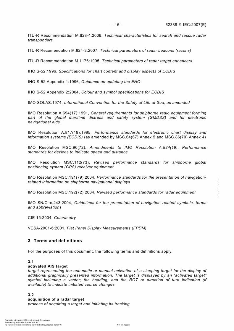
Table 1 – Performance requirements for categories of ship/craft for SOLAS V
Category of ship/craft
CAT 3 CAT 2 CAT 1
Size of ship/craft <500 gt 500 gt to <10 000 gt and HSC<10 000 gt
All ships/craft ≥10 000 gt
Minimum operational display area diameter 180 mm 250 mm 320 mm
Minimum display area 195 mm x 195 mm 270 mm x 270 mm 340 mm x 340 mm
Auto acquisition of targets - - Yes
Minimum acquired radar target capacity 20 30 40
Minimum activated AIS target capacity 20 30 40
Minimum sleeping AIS target capacity 100 150 200
Trial manoeuvre - - Yes
NOTE The processing capacity of AIS information should be in accordance with 10.5.2.
2 Normative references
The following referenced documents are indispensable for the application of this document. For dated references, only the edition cited applies. For undated references, the latest edition of the referenced document (including any amendments) applies.
IEC 60945, Maritime navigation and radiocommunication equipment and systems – General requirements – Methods of testing and required test results
IEC 61162 (all parts), Maritime navigation and radiocommunication equipment and systems – Digital interfaces
IEC 61174, Maritime navigation and radiocommunication equipment and systems – Electronic chart display and information systems (ECDIS) – Operational and performance requirements, methods of testing and required test results
IEC 61966-4, Multimedia systems and equipment – Colour measurement and management – Part 4: Equipment using liquid crystal display panels
IEC 61996 (all parts), Maritime navigation and radiocommunication equipment and systems –Shipborne voyage data recorder (VDR) – Performance requirements – Methods of testing and required test results
ISO 9000, Quality management systems – Fundamentals and vocabulary
ISO 9241-8, Ergonomic requirements for office work with visual display terminals (VDTs) –Part 8: Requirements for displayed colours
ISO 9241-12, Ergonomic requirements for office work with visual display terminals (VDTs) –Part 12: Presentation of information
ISO 13406-2, Ergonomic requirements for work with visual displays based on flat panels – Part 2: Ergonomic requirements for flat panel displays
ISO 80416-4, Basic principles for graphical symbols for use on equipment – Part 4: Guidelines for the adaptation of graphical symbols for use on screens and displays (icons)
Copyright International Electrotechnical Commission Provided by IHS under license with IEC
Not for ResaleNo reproduction or networking permitted without license from IHS
--`,,```,,,,````-`-`,,`,,`,`,,`---
– 16 – 62388 © IEC:2007(E)
ITU-R Recommendation M.628-4:2006, Technical characteristics for search and rescue radar transponders
ITU-R Recomendation M.824-3:2007, Technical parameters of radar beacons (racons)
ITU-R Recommendation M.1176:1995, Technical parameters of radar target enhancers
IHO S-52:1996, Specifications for chart content and display aspects of ECDIS
IHO S-52 Appendix 1:1996, Guidance on updating the ENC
IHO S-52 Appendix 2:2004, Colour and symbol specifications for ECDIS
IMO SOLAS:1974, International Convention for the Safety of Life at Sea, as amended
IMO Resolution A.694(17):1991, General requirements for shipborne radio equipment forming part of the global maritime distress and safety system (GMDSS) and for electronic navigational aids
IMO Resolution A.817(19):1995, Performance standards for electronic chart display and information systems (ECDIS) (as amended by MSC.64(67) Annex 5 and MSC.86(70) Annex 4)
IMO Resolution MSC.96(72), Amendments to IMO Resolution A.824(19), Performance standards for devices to indicate speed and distance
IMO Resolution MSC.112(73), Revised performance standards for shipborne global positioning system (GPS) receiver equipment
IMO Resolution MSC.191(79):2004, Performance standards for the presentation of navigation-related information on shipborne navigational displays
IMO Resolution MSC.192(72):2004, Revised performance standards for radar equipment
IMO SN/Circ.243:2004, Guidelines for the presentation of navigation related symbols, terms and abbreviations
CIE 15:2004, Colorimetry
VESA-2001-6:2001, Flat Panel Display Measurements (FPDM)
3 Terms and definitions
For the purposes of this document, the following terms and definitions apply.
3.1 activated AIS target target representing the automatic or manual activation of a sleeping target for the display of additional graphically presented information. The target is displayed by an “activated target” symbol including a vector; the heading; and the ROT or direction of turn indication (if available) to indicate initiated course changes
3.2 acquisition of a radar target process of acquiring a target and initiating its tracking
Copyright International Electrotechnical Commission Provided by IHS under license with IEC
Not for ResaleNo reproduction or networking permitted without license from IHS
--`,,```,,,,````-`-`,,`,,`,`,,`---

62388 © IEC:2007(E) – 17 –
3.3 activation of an AIS target activation of a sleeping AIS target for the display of additional graphical and alphanumerical information
3.4 acquired radar target automatic or manual acquisition initiates radar tracking. Vectors and past positions (if provided) are displayed when data has achieved a steady state condition (after 1 min)
3.5 automatic identification system AIS Automatic Identification System which complies with the requirements of IMO resolution MSC.74(69) Annex 3 and IEC 61993-2
3.6 AIS target target generated from an AIS message
3.7 associated target target simultaneously representing a tracked target and a reported AIS target having similar parameters (for example position, course, speed) which comply with an association algorithm
3.8 acquisition/activation zone zone set up by the operator in which the system should automatically acquire radar targets and activate reported AIS targets when entering the zone
3.9 azimuth-stabilised heading reference input, for example own ship’s gyro, is used to orientate the heading line on the radar display so that it points from the CCRP to own ship’s referenced heading on the bearing scale
3.10 bow crossing range/bow crossing time BCR/BCT measurements presented as from the bow of the ship as opposed to the CCRP
3.11 cardinal points (compass) 0, 090, 180, 270 compass points
3.12 consistent common reference point CCRP location on own ship, to which all horizontal measurements such as target range, bearing, relative course, relative speed, closest point of approach (CPA) or time to closest point of approach (TCPA) are referenced, typically the conning position of the bridge
3.13 closest point of approach/time to the closest point of approach CPA/TCPA distance to the closest point of approach (CPA) and time to the closest point of approach (TCPA). Limits are set by the operator and are related to own ship
Copyright International Electrotechnical Commission Provided by IHS under license with IEC
Not for ResaleNo reproduction or networking permitted without license from IHS
--`,,```,,,,````-`-`,,`,,`,`,,`---

– 18 – 62388 © IEC:2007(E)
3.14 course direction in which the ship is moving or intended to move, expressed in degrees from North, usually from 000° at north, then in a clockwise direction through 360°
3.15 course over ground COG direction of the ship's movement relative to the earth, measured on board the ship, expressed in angular units from true north
3.16 course through water CTW direction of the ship's movement through the water, defined by the angle between the meridian through its position and the direction of the ship's movement through the water, expressed in angular units from true north
3.17 course-up C-up azimuth-stabilised display in which the bearing scale can be orientated so that own ship’s course on the bearing scale is vertically above the CCRP. The heading line will continue to point from the CCRP to own ship’s referenced heading on the bearing scale. If own ship’s heading differs from the course, then the heading line will not point vertically upwards from the CCRP until the bearing scale is reset (manually or automatically) to reflect the course alteration
3.18 dangerous target target whose predicted CPA and TCPA are violating the values as preset by the operator. The respective target is marked by a “dangerous target” symbol
3.19 default predefined condition set either by the user or the equipment manufacturer
3.20 ECDIS Electronic Chart Display and Information System, which complies with IMO resolution A.817(19) amended by MSC.64(67) Annex 5 and MSC.86(70) Annex 4, and IEC 61174
3.21 ECDIS display base level of information which cannot be removed from the ECDIS display, consisting of information which is required at all times in all geographic areas and all circumstances. It is not intended to be sufficient for safe navigation
3.22 ECDIS standard display level of information that should be shown when a chart is first displayed on ECDIS. The level of the information it provides for route planning or route monitoring may be modified by the mariner according to the mariner's needs
3.23 electronic navigational chart ENC database standardised as to content, structure and format according to relevant IHO standards and issued by, or on the authority of, a Government
Copyright International Electrotechnical Commission Provided by IHS under license with IEC
Not for ResaleNo reproduction or networking permitted without license from IHS
--`,,```,,,,````-`-`,,`,,`,`,,`---
62388 © IEC:2007(E) – 19 –
3.24 electronic position fixing system EPFS position fixing system using electronic means
3.25 electronic range and bearing line ERBL electronic bearing line carrying a marker, which is combined with the variable range marker, used to measure range and bearing from own ship or between two objects
3.26 EUT equipment under test
3.27 evaporation duct low lying duct (a change in air density) that traps the radar energy so that it propagates close to the sea surface. Ducting may enhance or reduce radar target detection ranges
3.28 exclusion zone area which may exclude the automatic acquisition for target tracking and/or may suppress the automatic activation of sleeping AIS targets
3.29 ground stabilisation display mode in which speed and course information are referred to the ground, using ground track input data, or EPFS as reference
3.30 heading horizontal direction that the bow of a ship is pointing at any instant, expressed in angular units from a reference direction
3.31 heading line graphic line on a radar presentation drawn from the consistent common reference point to the bearing scale to indicate the heading of the ship
3.32 head-up H-up presentation mode which is orientated “up” toward the top of the bearing scale. Radar echoes and tracked targets are shown at their measured distances and moving in a direction relative to own ship’s heading. In head-up, the top of the bearing scale shows 000 degrees. Target trails are relative. It is possible to have an azimuth stabilised head-up mode where the top of the bearing scale shows own ship’s heading. In this case, target trails may be true or relative
3.33 high speed craft HSC vessels which comply with the definition in SOLAS for high speed craft
3.34 icon graphic that provides or signifies a control function capability
Copyright International Electrotechnical Commission Provided by IHS under license with IEC
Not for ResaleNo reproduction or networking permitted without license from IHS
--`,,```,,,,````-`-`,,`,,`,`,,`---
– 20 – 62388 © IEC:2007(E)
3.35 integrated navigation system INS navigation system which complies with the requirements of Annex 3 to IMO resolution MSC.86(70) and IEC 61924
3.36 latency delay between actual data received by the equipment and the presentation or use of that data
3.37 lost AIS target target symbol representing the last valid position of an AIS target before the reception of its data was lost, or its last dead-reckoned (DR) position. The target is displayed by a “lost AIS target” symbol
3.38 lost tracked target one for which target information is no longer available due to poor, lost or obscured signals. The target is displayed by a “lost tracked radar target” symbol at its last known or dead-reckoned position
3.39 maps/navigation lines operator defined or created lines to indicate channels, traffic separation schemes or borders of any area important for navigation
3.40 menu area of display that is allocated to the interactive display and operation of a structured menu for the selection and entry of operational parameters, data and commands. The menu display, when selected, is typically replacing parts of, or the whole, data display
3.41 navigation situation broad and general description of the type of navigation that is planned or being conducted, for example open ocean, coastal, approach, confined waters, restricted, docking/manoeuvring
3.42 non-volatile and transferable memory memory which retains its data when it is not provided with power and removed from one equipment or module, and fitted to another equipment or module
3.43 north-up N-up azimuth-stabilised presentation in which north on the bearing scale remains fixed vertically above the CCRP. The heading line points from the CCRP to own ship’s referenced heading on the bearing scale, and the bearing of any target on the display is measured from north. Such a bearing is commonly referred to as a true bearing when the heading reference input comes from a gyro aligned with true north
3.44 operational display area area of the display used to graphically present chart and radar information, excluding the user dialogue area. On the chart display this is the area of the chart presentation. On the radar display this is the area encompassing the radar image
Copyright International Electrotechnical Commission Provided by IHS under license with IEC
Not for ResaleNo reproduction or networking permitted without license from IHS
--`,,```,,,,````-`-`,,`,,`,`,,`---
62388 © IEC:2007(E) – 21 –
3.45 operational mode primary function of the presentation selected by the user, for the task at hand or navigation situation, for example radar, chart, conning
3.46 past positions equally time-spaced past position marks of a tracked or reported target and own ship. The past positions’ track may be either relative or true, and may apply to tracked radar targets or AIS targets
3.47 presentation mode result of the combination of user selected parameters that affect the display of information, for example azimuth orientation, motion, stabilisation, chart projection
3.48 protected menu one which is not easily accessed by the user and access may be, for example by a password or a switch
3.49 radar abbreviation for radio direction and ranging. It is a radio frequency system that allows the determination of distance and direction of reflecting objects and of transmitting devices
3.50 radar beacon navigation aid which responds to the radar transmission by generating a radar signal to identify its position and identity
3.51 radar cross-section RCS determines the power density returned to the radar for a particular power density incident on a target
3.52 radar detection false alarm probability of a radar false alarm represents the probability that noise will cross the detection threshold and be called a target when only noise is present
3.53 radar display module of a radar system, consisting of the presentation hardware
3.54 radar echo signal reflected by a target to a radar antenna that appears in the radar video signal and radar image
3.55 radar image plan view of the radar video in range and bearing
3.56 radar presentation display of a radar image together with related alpha-numeric and graphical information
Copyright International Electrotechnical Commission Provided by IHS under license with IEC
Not for ResaleNo reproduction or networking permitted without license from IHS
--`,,```,,,,````-`-`,,`,,`,`,,`---
– 22 – 62388 © IEC:2007(E)
3.57 radar system entire content and functionality of a system necessary to meet the requirements of this test standard
3.58 radar target object, fixed or moving, which is detected or detectable by a radar system and has a motion determined by successive radar measurements of range and bearing. A radar target is derived from video signals provided by the radar sensor (transceiver) and which appears in the radar image
3.59 radar video signal produced by a radar receiver as a result of radar echoes returned
3.60 radar target enhancer electronic radar reflector, the output of which is an amplified version of the received radar pulse without any form of processing except limiting
3.61 range index delay delay provided at the start of a radar presentation causing the near range radar signal contents to effectively be suppressed and distorting the linear plan presentation
3.62 rate of turn ROT change of heading per time unit
3.63 reference target symbol indicating that the associated tracked stationary target (for example a navigational mark) is used as a speed reference for the ground stabilisation
3.64 relative bearing direction of a target’s position from own ship’s CCRP expressed as an angular displacement from own ship’s heading
3.65 relative course direction of motion of a target relative to own ship’s direction (bearing)
3.66 relative motion RM display on which the position of own ship remains fixed, and all targets move relative to own ship. It is the combination of relative course and relative speed
3.67 relative speed speed of a target relative to own ship’s speed data
3.68 relative vector predicted movement of a target relative to own ship’s motion
Copyright International Electrotechnical Commission Provided by IHS under license with IEC
Not for ResaleNo reproduction or networking permitted without license from IHS
--`,,```,,,,````-`-`,,`,,`,`,,`---

62388 © IEC:2007(E) – 23 –
3.69 search and rescue transponder SART radar transponder capable of operating in the 9 GHz band
3.70 speed and distance measuring equipment SDME Speed and Distance Measuring Equipment which complies with IMO Resolution MSC.96(72)
3.71 sea state status of the sea condition due to the weather environment, expressed as a sea state 0 for flat conditions with minimal wind, to sea state 8 for very rough sea conditions
3.72 selected target manually selected target for the display of detailed alphanumeric information in a separate data display area. The target is identified by a “selected target” symbol
3.73 sleeping AIS target target indicating the presence and orientation of a vessel equipped with AIS in a certain location. The target is displayed by a “sleeping target” symbol. No additional information is presented until the target is activated
3.74 sea stabilisation display mode in which speed and course information are referred to the sea, using gyro or equivalent and water speed log input as reference
3.75 safety of life at sea SOLAS International Convention for the Safety of Life at Sea adopted by the International Conference on Safety of Life at Sea convened by the International Maritime Organization (IMO) in 1974
3.76 speed over ground SOG speed of the ship relative to the earth, measured on board of the ship
3.77 speed through water STW speed of the ship relative to the water surface
3.78 standard display level of information that should be shown when a chart is first displayed on ECDIS or ECS. The level of the information it provides for route planning or route monitoring may be modified by the mariner according to the mariner's needs
3.79 steady state tracking tracking a target, proceeding at steady motion:
– after completion of the acquisition process, or
Copyright International Electrotechnical Commission Provided by IHS under license with IEC
Not for ResaleNo reproduction or networking permitted without license from IHS
--`,,```,,,,````-`-`,,`,,`,`,,`---
– 24 – 62388 © IEC:2007(E)
– without a manoeuvre of target or own ship, or – without target swap or any disturbance
3.80 stern line graphic line drawn from the consistent common reference point to the bearing scale, on a reciprocal bearing to the heading line
3.81 target swap situation in which the incoming radar data for a tracked target becomes incorrectly associated with another tracked target or a non-tracked radar echo
3.82 target’s predicted motion prediction of a target’s future course and speed based on its present motion as determined by past measurements of its range and bearing on the radar
3.83 target tracking TT computer process of observing the sequential changes in the position of a radar target in order to establish its motion. Such a target is a Tracked Target
3.84 task at hand specific activity being performed by the user, for example collision avoidance, route planning, route monitoring, grounding avoidance
3.85 test target radar target of known characteristics used for test requirement
3.86 trails tracks displayed by the radar echoes of targets in the form of an afterglow. Trails may be true or relative. Relative trails are as they would be presented in relative motion. True trails are as they would be presented in true motion
3.87 trial manoeuvre graphical simulation facility used to assist the operator to perform a proposed manoeuvre for navigation and collision avoidance purposes, by displaying the predicted future status of at least all acquired or activated targets as a result of own ship’s simulated manoeuvres
3.88 true bearing direction of a target from own ship’s CCRP or from another target’s position, expressed as an angular displacement from true north
3.89 true course direction of motion relative to ground or to sea, of a target expressed as an angular displacement from north
Copyright International Electrotechnical Commission Provided by IHS under license with IEC
Not for ResaleNo reproduction or networking permitted without license from IHS
--`,,```,,,,````-`-`,,`,,`,`,,`---

62388 © IEC:2007(E) – 25 –
3.90 true motion TM display across which own ship moves with its own true motion. It is the combination of true course and true speed
3.91 true speed speed of a target relative to ground, or to sea
3.92 true vector vector representing the predicted true motion of a target, showing course and speed with reference to the ground or sea
3.93 user configured presentation display presentation configured by the user for a specific task at hand. The presentation may include radar and/or chart information, in combination with other navigation or ship related data
3.94 user-defined result of a function or parameter selected or defined by the user within the confines of specific equipment
3.95 user dialogue area area of the display consisting of data fields and/or menus that is allocated to the interactive presentation and entry or selection of operational parameters, data and commands mainly in alphanumeric form
3.96 VDR voyage data recorder
3.97 waypoint wpt position at which a turn is executed
4 General
4.1 Establishing equipment type and status
The manufacturer shall state the intended system content and the category of equipment under test (EUT). Specific requirements, which shall include intended equipment category, are listed below:
• high speed or normal speed. (MSC.192/5.3.1.1) Recognising the high relative speeds possible between own ship and target, the equipment shall be specified and approved as being suitable for classes of ship having normal (≤30 kn) or high (>30 kn) own ship speed (100 kn and 140 kn relative speeds respectively);
• frequency band (X-band and/or S-band) and operational frequency limits;
• declaration of any novel processing, new technology or additional functionality which requires alternative testing or claims equivalency to the requirements;
• list all variants (up-mast/down-mast, split processor/displays, chart option, etc);
Copyright International Electrotechnical Commission Provided by IHS under license with IEC
Not for ResaleNo reproduction or networking permitted without license from IHS
--`,,```,,,,````-`-`,,`,,`,`,,`---

– 26 – 62388 © IEC:2007(E)
• identification of all antennas available with the radar. The smallest antenna (or its properties) shall be used for all relevant performance testing. Environmental testing (vibration and shock) shall use the largest antenna available;
• all ancillary units (inter-switching, buffer amplifiers, etc);
• units intended for protected (from the weather) or exposed (to the weather) application;
• the intended separation (cable, network or transmission line/feeder) between units. When equipment with separate transmitter and antenna is tested in accordance with this standard, the transmitter/receiver shall be connected to the antenna by a 20 m (minimum) of feeder. The display shall be connected to other units by 65 m of cable. Where equipment is type tested, in which the transmitter and receiver are always installed within the antenna/pedestal combination, the 20 m of antenna feeder shall be omitted. Where necessary, the manufacturer shall supply the appropriate cable and antenna feeder. The manufacturer, or its representative, may propose to the test authority for consideration, a greater distance by which units of the equipment may be separated and still comply with the requirements of this standard. The actual distance requested and tested shall be recorded;
• power supply requirements and declared nominal voltage/frequency of operation. The supply voltage applied to the equipment during the tests shall be the nominal voltage, and alternating current (a.c.) supplies shall be at nominal frequency unless specified otherwise;
• intended equipment configuration(s), either as standalone or as part of a system;
• the manufacturer’s code numbers for each piece of equipment and its ancillaries;
• familiarisation documentation or media;
• evidence of sea trials as required by 5.9.3.
4.2 Conditions of measurement and related definitions
All the general requirements of IEC 60945 shall be carried out on the same type of equipment under test (EUT) to verify whether the EUT meets these technical requirements. The equipment shall comply with those requirements of IEC 60945 appropriate to its category, i.e. 'protected' (from the weather) or 'exposed' (to the weather). Accordingly, the manufacturer shall declare which equipment or units are intended to be ‘protected’ or ‘exposed’. The manufacturer shall declare any ‘preconditioning’ required before environmental checks.
4.3 Test sites and simulation
4.3.1 Environmental and RF testing
Testing for general, environmental and radio frequency measurements shall be conducted in a test house, or location, accepted by the test authority and by competent persons familiar with the radar application.
4.3.2 Over-sea radar performance tests
Many of the tests may be conducted on land at a test site accepted by the test authority. Specific testing shall be required over sea and these may be shore based or at sea on a test ship.
Radar performance tests will normally be carried out at test sites selected by the type test authority. These test sites shall provide an over water test range with test targets and the features required for specified tests. The operational performance testing in this standard shall be conducted with a nominal antenna height of 15 m.
The manufacturer shall, unless otherwise agreed, set up the equipment and ensure that it is operating normally before type testing commences.
Copyright International Electrotechnical Commission Provided by IHS under license with IEC
Not for ResaleNo reproduction or networking permitted without license from IHS
--`,,```,,,,````-`-`,,`,,`,`,,`---

62388 © IEC:2007(E) – 27 –
4.3.3 Test targets and target simulation for performance tests
Standard targets used for the radar performance measurement and assessment are described in the relevant tests.
The target scenario simulator provides test scenarios to assess the tracking performance of the EUT, in accordance with Annex F.
The reported target simulator provides the test scenario for testing the AIS target functions and for target association, in accordance with Annex F.
Simulators used for testing shall be suitably calibrated or verified before use for measurement.
4.4 Quality requirements
The equipment and documentation shall be developed, produced and written in accordance with a recognised quality procedure, for example ISO 9000 or an equivalent recognised quality standard.
4.5 Test terminology and format
4.5.1 General
For each test subject, there is a requirement subclause (for example referenced to (MSC.192/clause) and a corresponding compliance subclause, which includes a test method and the required result.
4.5.2 Test requirement terminology
For the purposes of this standard, the following test terminology shall apply:
performance check – reconfiguration of the EUT and checking by non-quantitative visual checks that the system is still operative for the purposes of IEC 60945. This shall include the operation of basic functionality to confirm normal operation;
performance test – for the radar EUT, shall be of an identical standard to that used in the performance check for the purposes of IEC 60945, with the addition of a specified test as described in Clause 16;
clear indication or visibility of test targets – visible for at least 8 out of 10 of the antenna scans, or indication 5 out of 10 with past positions, synthetic afterglow and trails facility switched off;
single operator action – the use of a single hardware key or, the use of the cursor to select a single display icon or window followed by the operation of a key;
dedicated control function – the use of a dedicated single hardware key or, the use of the cursor to select a single dedicated display icon or window followed by the operation of a key;
momentary control function – the use of a dedicated single hardware key or, the use of the cursor to select a single dedicated display icon or window followed by the operation of a key. The control function shall only operate while the key is pushed;
readily available – applies to information or to a function for the selected application, which is available in a top level menu and accessed directly from a screen function or icon, or by a dedicated control;
Copyright International Electrotechnical Commission Provided by IHS under license with IEC
Not for ResaleNo reproduction or networking permitted without license from IHS
--`,,```,,,,````-`-`,,`,,`,`,,`---

– 28 – 62388 © IEC:2007(E)
permanent indication – applies to a status indication permanently or persistently available (as appropriate) and visible at any time that the equipment is operational;
protected menu – is one which is not easily accessed by the user and protected for example, by a password, internal switch or hardware link;
means – “a means to” do something is equivalent to “a method of” something, for example “a means to measure between two points” is the same as “a method of measuring”.
4.5.3 Testing method terminology
Testing method terminology is derived from ISO 9241-12 and for application to this radar standard, terms are defined as:
measurement – refers to measurement or calculation of a variable concerning the presentation of information, accuracy, or the equipment performance;
observation – means to examine or inspect the equipment to confirm that a particular observable condition has been met. Observations can be made by anyone who has the necessary skill to systematically check the presentation of information and make the determination;
document inspection – means to confirm by inspection that any relevant documented information, facility or function is compliant with the requirement;
analytical evaluation – requires the informed judgement of equipment performance from a study of observations or measurements by an expert, a suitably qualified person who has the necessary skill and experience to judge the relevant property in the relevant subject. The method is typically used for the evaluation of properties which can be judged only in the context of other information or knowledge.
5 Radar performance
5.1 General
The performance test shall include measurement of the transmission frequency spectrum, familiarisation of the controls and signal processing functions, followed by minimum range, discrimination and accuracy measurements. The performance assessment in an over-sea environment shall exercise the signal processing and associated control functions. During this assessment, the test authority shall familiarise themselves with the gain and anti-clutter functions. Detection performance testing is provided in 5.9.
NOTE Radar provides the primary means to detect surface hazards for safe navigation and therefore the detection of surface hazards is a primary element in the task of collision avoidance. The performance requirements should address the fundamental radar transmission, detection and signal processing capability of the radar system.
5.2 Transmission and interference
Transmission frequency parameters are measured and the reduction of radiated interference from other sources is assessed.
5.2.1 Transmission frequency
5.2.1.1 Requirement
(MSC.192/5.1.1) The radar shall transmit within the confines of the ITU allocated bands for maritime radar and meet the requirements of the radio regulations and applicable ITU-R recommendations.
Copyright International Electrotechnical Commission Provided by IHS under license with IEC
Not for ResaleNo reproduction or networking permitted without license from IHS
--`,,```,,,,````-`-`,,`,,`,`,,`---
62388 © IEC:2007(E) – 29 –
(MSC.192/5.1.2) Radar systems of both X-band and S-band are covered in these performance standards:
– X-band (9,2-9,5 GHz) for high discrimination, good sensitivity and tracking performance; and
– S-band (2,9-3,1 GHz) to ensure that target detection and tracking capabilities are maintained in varying and adverse conditions of fog, rain and sea clutter.
The frequency band selected shall be indicated.
5.2.1.2 Methods of test and required results
The methods of test and required results are as follows:
a) confirm by measurement and analytical evaluation that the EUT meets the results required by the method described in Annex B of this standard. The test authority shall record the transmitted frequency or frequencies;
b) confirm by observation that there is an indication of the selected frequency band in use.
5.2.2 Interference
5.2.2.1 Requirement
(MSC.192/5.1.3) The radar shall be capable of operating satisfactorily in typical interference conditions as encountered in a normal marine radar environment.
5.2.2.2 Methods of test and required results
The methods of test and the required results are as follows:
a) confirm by analytical evaluation that the radar system has a method to substantially reduce interference from other approved marine radar transmitting in the frequency bands allocated to marine radar;
b) confirm by analytical evaluation that the radar system can transmit in the vicinity of other approved marine radar systems without causing significant interference or significant degradation in performance.
NOTE Radar detection performance specified in this standard may be degraded by third party interference, possibly by equipment other than marine radar, radiated within the bands assigned to marine applications.
5.3 Performance optimisation and monitoring
5.3.1 General
The radar system shall provide the means to optimise detection performance and to identify a significant drop in performance, as tested in 5.3.2.
5.3.2 Optimum performance
5.3.2.1 Requirement
(MSC.192/5.7.1) Means shall be available to ensure that the radar system is operating at the best performance. Where applicable to the radar technology, manual tuning shall be provided and additionally, automatic tuning may be provided.
(MSC.192/5.7.2) An indication shall be provided, in the absence of targets, to ensure that the system is operating at the optimum performance.
(MSC.192/5.7.3) Means shall be available (automatically or by manual operation) and while the equipment is operational, to determine a significant drop in system performance relative to a calibrated standard established at the time of installation.
Copyright International Electrotechnical Commission Provided by IHS under license with IEC
Not for ResaleNo reproduction or networking permitted without license from IHS
--`,,```,,,,````-`-`,,`,,`,`,,`---

– 30 – 62388 © IEC:2007(E)
5.3.2.2 Methods of test and required results
The methods of test and the required results are as follows:
a) confirm by observation that the operation of the tuning function (or equivalent as applicable to the technology) is effective. The user manual shall describe how optimum performance is maintained;
b) confirm by observation there is a manual or automatic means to indicate that the radar system is operating at the optimum performance, even in the absence of targets, for example with the provision of a tuning indicator;
c) if automatic tuning is provided, confirm by analytical evaluation that it is not inferior to the performance achieved with manual tuning;
d) confirm by observation that when the overall radar performance is reduced by using an attenuator or equivalent means, an overall 10 dB performance reduction or more is identified by an indication to the operator. An up-mast system may be accepted by analogy with a down-mast system, given an equivalent implementation and equipment design.
5.4 Gain and anti-clutter functions
5.4.1 General
This standard specifies control functions associated with processing or controlling the radar signals. If alternative means to achieve equivalent functionality is provided, the manufacturer shall identify the means and shall demonstrate equivalence, supported by the relevant user documentation and to the satisfaction of the test authority.
(MSC.192/5.3.2) Means shall be provided, as far as is possible for the adequate reduction of unwanted echoes, including sea clutter, rain and other forms of precipitation, clouds, sandstorms and interference from other radars.
Conformance with these requirements is addressed in 5.4.2 to 5.5.8 and the operation of functions is assessed in 5.9.
5.4.2 Gain function
5.4.2.1 Requirement
(MSC.192/5.3.2.2) A gain control function shall be provided to set the system gain or signal threshold level. A permanent indication of the gain level or setting of the signal threshold shall be given.
5.4.2.2 Methods of test and required results
The methods of test and the required results are as follows:
a) confirm by observation that there is a permanent indication of the gain level; b) confirm by observation that the control function is directly accessible; c) confirm by evaluation and observation that the gain control coverage varies from a
maximum level, providing a full noise speckle on a 24 NM range scale, to a minimum level where only the highest signal levels are presented;
d) confirm by observation that, if a preset gain adjustment is provided, it is located in a protected set-up menu.
Copyright International Electrotechnical Commission Provided by IHS under license with IEC
Not for ResaleNo reproduction or networking permitted without license from IHS
--`,,```,,,,````-`-`,,`,,`,`,,`---

62388 © IEC:2007(E) – 31 –
5.4.3 Manual and automatic sea anti-clutter
5.4.3.1 Requirement
(MSC.192/5.3.2.3) Effective manual and automatic anti-clutter sea functions shall be provided.
(MSC.192/5.3.2.4) A combination of automatic and manual anti-clutter sea functions is permitted.
(MSC.192/5.3.2.5) There shall be a clear and permanent indication of the status for gain and all anti-clutter sea control functions.
5.4.3.2 Methods of test and required results
The methods of test and the required results are as follows:
a) confirm by observation that both “manual sea” and “automatic sea” functions are provided; b) confirm by document inspection that the user manual describes any installation and
operational adjustments associated with these functions and any performance limitations associated with their use;
c) confirm by document inspection that the user manual describes the operation of the manual and automatic anti-clutter sea control functions, including any advantages and limitations;
d) confirm by observation that the status and level of the functions are permanently indicated.
5.4.4 Rain anti-clutter
5.4.4.1 Requirement
An effective manual means of suppressing rain clutter shall be provided. Automatic rejection of rain clutter may also be provided. There shall be a clear and permanent indication of the status of the anti-clutter rain function.
5.4.4.2 Methods of test and required results
The methods of test and the required results are as follows:
a) confirm by observation the availability and operation of the rain anti-clutter control functions;
b) confirm by observation that the status and level of the rain anti-clutter function is permanently indicated;
c) confirm by document inspection that the user manual describes the use of the manual rain anti-clutter control (and automatic where provided), together with any performance limitations associated with its use.
5.5 Signal processing
5.5.1 General
Signal processing functions serve to improve target visibility and detection performance.
5.5.2 Target enhancement
5.5.2.1 Requirement
(MSC.192/5.3.1.3.2) The radar system shall provide the means to enhance the visibility of targets in adverse clutter conditions at close range.
Copyright International Electrotechnical Commission Provided by IHS under license with IEC
Not for ResaleNo reproduction or networking permitted without license from IHS
--`,,```,,,,````-`-`,,`,,`,`,,`---
– 32 – 62388 © IEC:2007(E)
(MSC.192/5.3.3.1) Means shall be available to enhance target visibility on the display. If selectable, the target enhance status shall be indicated and the user manual shall describe the operation and principles of the target enhance functions.
NOTE The function to enhance the visibility of targets in close ranges may use other processing techniques than those for standard navigation purposes.
5.5.2.2 Methods of test and required results
The methods of test and the required results are as follows:
a) confirm by observation that there are means to enhance target visibility in the clutter environment. The target enhancement functions may be selectable or permanent. If any associated functions are provided, for example to reduce a high false alarm rate, they may be enabled to reduce degradation of target visibility;
b) confirm by document inspection that the user manual describes the enhancement function(s) and principles, including any associated functions and their use;
c) confirm by observation that the target-enhance status is indicated.
5.5.3 Radar signal correlation
5.5.3.1 Requirement
Correlation of consecutive transmissions shall be provided to reduce unwanted interference from other radar systems. Scan to scan correlation may be used to reduce echoes from clutter.
5.5.3.2 Methods of test and required results
The methods of test and the required results are as follows:
a) confirm by document inspection and observation that a means is provided for the effective reduction of interference generated by other marine conventional (magnetron) radar;
b) confirm by document inspection that where correlation techniques are provided, for example to reduce clutter, any advantages and limitations are described in the user manual.
5.5.4 Signal processing and radar image latency
5.5.4.1 Requirement
(MSC.192/5.3.3.2) The effective signal processing and radar image update period shall be adequate and with minimum latency to ensure that the target detection and associated processing requirements are met.
5.5.4.2 Methods of test and required results
The methods of test and the required results are as follows:
a) confirm by observation and measurement that the update of any target information has a latency of not more than the equivalent of one antenna scan. Alternative correlation techniques are permitted to have a latency of multiple scans;
b) confirm by observation that the status of any correlation function is indicated; c) confirm by document inspection that the user manual describes the advantages and
limitations of any alternative correlation applied.
Copyright International Electrotechnical Commission Provided by IHS under license with IEC
Not for ResaleNo reproduction or networking permitted without license from IHS
--`,,```,,,,````-`-`,,`,,`,`,,`---

62388 © IEC:2007(E) – 33 –
5.5.5 Second-time-around echoes
5.5.5.1 Description
These echoes are a reflection of radar energy from a target due to a previous radar transmission which is prevalent in some atmospheric conditions. Second-time-around echoes appear as stable but false targets at any time (range) within the period between consecutive transmissions.
5.5.5.2 Requirement
A means of suppressing these second-time-around echoes may be provided and if provided, shall be tested.
5.5.5.3 Methods of test and required results
If a method for suppressing second time echoes is provided, then
a) confirm by observation, where conditions permit, during the testing of the radar equipment, that an effective means of reducing second time echoes is provided;
b) confirm by document inspection that the means provided to suppress second time echoes is described in the user manual.
5.5.6 Transmission format
5.5.6.1 Requirement
To optimise detection performance for the weather conditions, the equipment may provide a means to change the transmission format, for example by providing the ability to increase or to decrease the pulse length.
5.5.6.2 Methods of test and required results
If a means to change the transmission format is provided, then
a) confirm by document inspection, observation and analytical evaluation that appropriate default transmission formats are provided for each range scale;
b) confirm by observation that inappropriate transmission formats are inhibited or are indicated to the user, for example the long pulse length should be prohibited on shorter range scales;
c) confirm by document inspection that the function of changing the transmission format, if provided, is described in the user manual and the basic concept, features, benefits and limitations are stated.
5.5.7 Picture update
5.5.7.1 Requirement
(MSC.192/5.3.3.3) The picture shall be updated in a smooth and continuous manner.
5.5.7.2 Methods of test and required results
Confirm by observation that the radar image is updated smoothly and the method of update is not distracting to the user.
5.5.8 Additional processing
5.5.8.1 Requirement
Additional signal processing provided by the equipment shall be evaluated.
Copyright International Electrotechnical Commission Provided by IHS under license with IEC
Not for ResaleNo reproduction or networking permitted without license from IHS
--`,,```,,,,````-`-`,,`,,`,`,,`---
– 34 – 62388 © IEC:2007(E)
5.5.8.2 Methods of test and required results
The methods of test and the required results are as follows:
a) confirm by document inspection what additional signal processing functions are provided; b) record top level details of additional signal processing features and any observed impact
they have on the radar detection performance.
5.5.9 Signal processing description
5.5.9.1 Requirement
(MSC.192/5.3.3.4) The equipment manual shall explain the basic concept, features, benefits and limitations of any signal processing functions.
5.5.9.2 Methods of test and required results
The methods of test and the required results are as follows:
a) confirm by observation that the status of all selectable active signal processing functions is indicated;
b) confirm by document inspection that the functions are described in the user manual and that basic concepts, features, benefits and limitations are stated.
5.6 Operation with SARTs, target enhancers (RTEs) and beacons
5.6.1 General
X-band radar systems shall be compatible with radar beacons, SARTs and radar enhancers, while S-band radar systems may adopt new technology which may not be compatible with these navigation aids.
5.6.2 Radar beacons, SARTs and enhancers
5.6.2.1 Requirement
(MSC.192/5.3.4.1) The X-band radar system shall be capable of detecting radar beacons in the relevant frequency band.
(MSC.192/5.3.4.2) The X-band radar system shall be capable of detecting SARTs and radar target enhancers.
(MSC.192/5.3.4.3) It shall be possible to switch off those signal processing functions, including alternative polarisation modes, which might prevent an X-band radar beacon or SARTs from being detected and displayed. The status of signal processing and polarisation (if selectable) shall be indicated.
The operation of the equipment with beacons, SARTS and target enhancers shall be described in the user manual.
5.6.2.2 Methods of test and required results
The methods of test and the required results are as follows:
a) confirm by observation that the X-band equipment operates with a typical radar beacon. The equipment shall be set working overlooking the sea and in the vicinity of known radar beacons, to demonstrate that the EUT is compatible with ITU-R M.824-3 (beacons);
b) confirm by observation that when the X-band equipment is set working overlooking a sea environment and in the vicinity of known SARTs and radar enhancers, the system detects
Copyright International Electrotechnical Commission Provided by IHS under license with IEC
Not for ResaleNo reproduction or networking permitted without license from IHS
--`,,```,,,,````-`-`,,`,,`,`,,`---
62388 © IEC:2007(E) – 35 –
SARTs and radar enhancers, as required by ITU-R M.628-4 (SARTs) and ITU-R M.1176 (radar target enhancers);
c) confirm by observation that the status of signal processing and polarisation (if selectable) is indicated;
d) confirm by document inspection that the operation of the equipment with beacons, SARTs and target enhancers is described in the user manual.
5.7 Minimum range and range compensation
5.7.1 General
The minimum detection range for the radar system shall be measured after the range index error has been compensated for the selected antenna position.
5.7.2 Range compensation
5.7.2.1 Requirement
(MSC.192/5.4.2) Compensation for any range index error shall be provided and where multiple antennas are installed, shall be automatically applied for each selected antenna.
5.7.2.2 Methods of test and required results
The methods of test and the required results are as follows:
a) confirm by document inspection that the equipment provides the means to compensate for the range index for the position of each antenna and that the settings are protected in a non-volatile memory. Adjust the range compensation for each sensor (as applicable) so that the range of a known target is correct;
b) confirm by document inspection and observation that the compensation setting for each sensor is retained in a non-volatile memory and that it is automatically applied when each sensor is selected.
5.7.3 Minimum range
5.7.3.1 Requirement
(MSC.192/5.3.1.2) The short-range detection of the targets under the conditions specified in Table 2 shall be compatible with the requirement.
(MSC.192/5.4.1) With own vessel at zero speed (or at a fixed land-based site), an antenna height of 15 m above the sea level and in calm (minimal clutter) conditions, the navigational buoy (with corner reflector) in Table 2 shall be detected at a minimum horizontal range of 40 m from the antenna position and up to a range of 1 NM, without changing the setting of control functions other than the range scale selector.
Ensure that the range compensation is set correctly (as described in 5.7.2) before measurements are made. A test target, (equivalent to the navigational buoy with corner reflector) having a known RCS of 10 m2 at X-band (having a known RCS of 1 m2 at S-band) and mounted at a height of 3,5 m, shall be used.
5.7.3.2 Methods of test and required results
The methods of test and the required results are as follows:
a) confirm by observation and document inspection that if a down-mast transceiver is an option for the radar under test, the test is conducted using a down-mast transceiver, or otherwise the test shall be conducted with an up-mast unit. If the implementation of up-mast and down-mast systems is different, both types of systems shall be tested;
Copyright International Electrotechnical Commission Provided by IHS under license with IEC
Not for ResaleNo reproduction or networking permitted without license from IHS
--`,,```,,,,````-`-`,,`,,`,`,,`---
– 36 – 62388 © IEC:2007(E)
b) confirm by observation that a reference test target is available having the same properties as the mobile test target. The reference test target shall be stationary and positioned at 1 NM range. Adjust the radar system so that the reference test target at approximately 1 NM is clearly visible;
c) confirm by measurement that with the radar antenna mounted at the specified height, the separation of a mobile test target (representative of a navigational buoy) and the antenna position can be decreased to the closest point at which the target can be identified within 40 m of the antenna position. Record the result. After adjustment, the mobile test target at the minimum range and the reference target at 1 NM shall be visible with the same setting of the gain and clutter controls;
d) alternatively a mobile target with an RCS of 10 m2 at X-band may be used and moved from
the closest point at which the target is visible up to 1 NM with the same settings of the gain and clutter controls.
The minimum range is the shortest distance at which, using a mandatory range scale of not more than 1,5 NM, a stationary target is presented separately from the position and image representing the antenna position. The separation distance is measured horizontally from the sea/ground level at the antenna position.
For this measurement, only the range scale selector may be changed and the sea and gain controls may be adjusted before commencing this test. After adjustment, the test target shall be visible at the minimum range and at 1 NM with the same setting of the sea and gain control. An off-centred presentation is permitted for this measurement.
5.8 Range and bearing discrimination
5.8.1 General
Point test targets of the same RCS as those described in 5.7.3 shall be used for the range and bearing discrimination measurements.
5.8.2 Measurement conditions
(MSC.192/5.5) Range and bearing discrimination shall be measured in calm (minimal clutter) conditions, on a range scale of 1,5 NM or less and at between 50 % and 100 % of the range scale selected. An off-centred presentation is permitted for this test.
5.8.3 Range discrimination
5.8.3.1 Requirement
(MSC.192/5.5.1) The radar system shall be capable of displaying two point targets on the same bearing, separated by 40 m in range, as two distinct objects.
5.8.3.2 Methods of test and required results
The methods of test and the required results are as follows:
a) confirm the range discrimination by measurement. The radar shall be set to a range scale of 0,75 nautical miles. Two test targets as defined in 5.7.3 shall be placed on the same bearing with respect to the radar antenna, at a distance of between 0,375 nautical miles and 0,75 nautical miles, and separated from each other by a distance of not more than 40 m. The rain control and the effective pulse length of the radar shall be set to their minimum values. The sea and gain controls shall be adjusted to show separation of the two targets on the display;
b) when the two targets are visibly separated for at least 8 scans out of 10, the linear distance between the two targets shall be measured. Confirm that the distance is not greater than 40 m.
Copyright International Electrotechnical Commission Provided by IHS under license with IEC
Not for ResaleNo reproduction or networking permitted without license from IHS
--`,,```,,,,````-`-`,,`,,`,`,,`---
62388 © IEC:2007(E) – 37 –
5.8.4 Bearing discrimination
5.8.4.1 Requirement
(MSC.192/5.5.2) The radar system shall be capable of displaying two point targets at the same range, separated by 2,5° in bearing, as two distinct objects.
5.8.4.2 Methods of test and required results
The methods of test and the required results are as follows:
a) confirm the bearing discrimination by measurement. The radar shall be set to the range scale of 1,5 NM or less and the test targets positioned at between 60 % and 100 % of the range scale selected. Two test targets of equal radar cross-section and as defined in 5.7.3, shall be placed at the same distance and shall be separated in bearing with respect to the radar antenna. The measurement may be made at any convenient bearing from the antenna location. The angular separation between the two targets shall be decreased until they cease to be displayed separately. When the two targets are visibly separated for at least 8 scans out of 10 the linear distance between the two targets shall be measured;
b) confirm by calculation that the angle calculated with respect to the known range of the test targets does not exceed 2,5° and record the calculated angular separation.
5.8.5 Fundamental radar accuracy
5.8.5.1 Requirement
(MSC.192/5.2) The radar system range and bearing accuracy shall be:
Range: within 30 m or 1 % of the range scale in use, whichever is greater; Bearing: within 1°
in typical operational and environmental conditions.
5.8.5.2 Methods of test and required results
The methods of test and the required results are as follows:
a) bearing: confirm by measurement that when operating on a stationary platform, the overall accuracy of taking bearings by the radar system meets the bearing accuracy required. Measurement shall be by comparing the actual bearings of identifiable point targets with bearings obtained using the radar equipment. The comparison shall be made at sample bearings distributed over 360° and the distance of each target from the radar antenna shall be between 80 % and 100 % of the range scale in use. The bearing measurement can be made either by using a single point target positioned at a series of known bearings relative to the radar antenna pedestal, or by taking the radar bearing of a series of point targets at known surveyed bearings around the radar antenna pedestal;
b) range: confirm by measurement from a stable platform using actual ranges of identifiable point targets, that when operating on a stationary platform, the overall accuracy of making range measurements by the radar system meets the range accuracy required. Measurement shall use at least two known targets, the first at nominally 1 NM, the second at nominally 10 NM. The range accuracy shall be within 30 m or 1 % of the range scale in use, whichever is the greater, and record the result. The radar transceiver shall operate with the appropriate transmission format for this test.
5.9 Target detection performance assessment
5.9.1 General
This standard specifies the minimum range of first detection performance in clear conditions and in addition, defines clutter conditions in which compliance with the detection performance requirements are tested, measured or assessed, including:
Copyright International Electrotechnical Commission Provided by IHS under license with IEC
Not for ResaleNo reproduction or networking permitted without license from IHS
--`,,```,,,,````-`-`,,`,,`,`,,`---
– 38 – 62388 © IEC:2007(E)
a) measurement of the range of first detection in minimal clutter conditions. Observations shall be made to confirm the visibility of a test target and in addition, shall be generally consistent with the IMO requirements as in Table 2;
b) measurement/predictions of the range of first detection in the presence of clutter (between the antenna and the target) and the assessment of the target visibility in clutter conditions by observing test targets within the clutter field and/or rain extent, using sea states and rainfall rates of opportunity.
For all radar performance tests, the radar antenna shall be installed on a platform either at sea or shore-based. The antenna shall be mounted at a height as close as practical at 15 m above mean sea level, recognising that even small deviations in antenna and/or target height can influence target detection performance and will reposition multi-path nulls. To achieve consistency, the tests shall ensure that observations and measurements are made with the test targets positioned for detection at multi-path peaks. The radar antenna height and target parameters shall be documented by the test authority for each test. All test results shall be made available to the equipment manufacturer.
NOTE 1 If a representative radar system is used as a further means to assess detection performance, the antenna of both the test radar and the reference radar should be at the same height and as near as practical, co-located. A reference-radar should be demonstrated to have met the minimum requirements in this standard. It could provide an indication of the relative propagation and clutter conditions at the time of the test measurements. A pass/fail decision should not only rely on comparison with a reference-radar.
NOTE 2 All radar performance documentation requirements are addressed in 5.9.4.
5.9.2 Range of first detection in minimal clutter
5.9.2.1 Requirement
(MSC.192/5.3.1.1) In the absence of clutter, for long range and small target and shoreline detection, the requirement for the radar system is based on normal propagation conditions, in the absence of significant sea clutter, precipitation and evaporation duct, and with an antenna height of 15 m above sea level.
Based on:
– an indication of the target in at least 8 out of 10 scans or equivalent; and – a probability of a radar detection false alarm of 10–4,
the requirement contained in Table 2 shall be met as specified for X-band and S-band equipment. The detection performance shall be achieved using the smallest antenna that is supplied with the radar system. A probability of a radar false alarm rate of 10–4 can be assumed when a light and even background noise speckle is presented on the display.
NOTE If the set-up of false alarm rate of 10–4 visible as a light and even background noise speckle is not applicable for the radar under test, the manufacturer should provide a method to achieve an equivalent set-up.
Copyright International Electrotechnical Commission Provided by IHS under license with IEC
Not for ResaleNo reproduction or networking permitted without license from IHS
--`,,```,,,,````-`-`,,`,,`,`,,`---
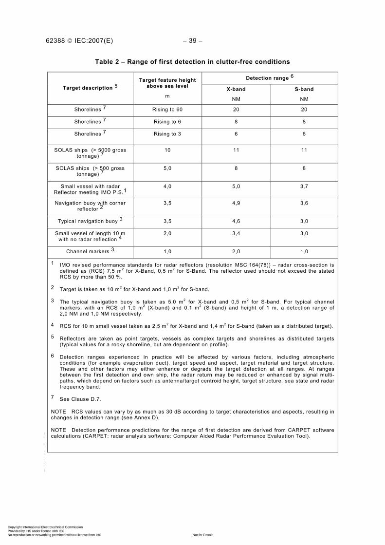
62388 © IEC:2007(E) – 39 –
Table 2 – Range of first detection in clutter-free conditions
Detection range 6
Target description 5 Target feature height
above sea level
m X-band
NM
S-band
NM
Shorelines 7 Rising to 60 20 20
Shorelines 7 Rising to 6 8 8
Shorelines 7 Rising to 3 6 6
SOLAS ships (> 5000 gross tonnage) 7
10 11 11
SOLAS ships (> 500 gross tonnage) 7
5,0 8 8
Small vessel with radar Reflector meeting IMO P.S.1
4,0 5,0 3,7
Navigation buoy with corner reflector 2
3,5 4,9 3,6
Typical navigation buoy 3 3,5 4,6 3,0
Small vessel of length 10 m with no radar reflection 4
2,0 3,4 3,0
Channel markers 3 1,0 2,0 1,0
1 IMO revised performance standards for radar reflectors (resolution MSC.164(78)) – radar cross-section is defined as (RCS) 7,5 m2 for X-Band, 0,5 m2 for S-Band. The reflector used should not exceed the stated RCS by more than 50 %.
2 Target is taken as 10 m2 for X-band and 1,0 m2 for S-band.
3 The typical navigation buoy is taken as 5,0 m2 for X-band and 0,5 m2 for S-band. For typical channel markers, with an RCS of 1,0 m2 (X-band) and 0,1 m2 (S-band) and height of 1 m, a detection range of 2,0 NM and 1,0 NM respectively.
4 RCS for 10 m small vessel taken as 2,5 m2 for X-band and 1,4 m2 for S-band (taken as a distributed target).
5 Reflectors are taken as point targets, vessels as complex targets and shorelines as distributed targets (typical values for a rocky shoreline, but are dependent on profile).
6 Detection ranges experienced in practice will be affected by various factors, including atmospheric conditions (for example evaporation duct), target speed and aspect, target material and target structure. These and other factors may either enhance or degrade the target detection at all ranges. At ranges between the first detection and own ship, the radar return may be reduced or enhanced by signal multi-paths, which depend on factors such as antenna/target centroid height, target structure, sea state and radar frequency band.
7 See Clause D.7.
NOTE RCS values can vary by as much as 30 dB according to target characteristics and aspects, resulting in changes in detection range (see Annex D).
NOTE Detection performance predictions for the range of first detection are derived from CARPET software calculations (CARPET: radar analysis software: Computer Aided Radar Performance Evaluation Tool).
Copyright International Electrotechnical Commission Provided by IHS under license with IEC
Not for ResaleNo reproduction or networking permitted without license from IHS
--`,,```,,,,````-`-`,,`,,`,`,,`---

– 40 – 62388 © IEC:2007(E)
5.9.2.2 Methods of test and required results
The methods of test and the required results are as follows:
a) confirm by observation and document inspection that the smallest antenna (at the test frequency band) available for use with the radar system is installed. Adjust the system for best target visibility with a light and even background noise speckle to provide good detection sensitivity. The sea conditions shall be calm for assessing range of first detection (maximum sea state 1, see Table 6 for guidance on sea states). The test may be conducted from a land site overlooking the sea or from a stable platform at sea. All observations shall be conducted in clear conditions;
b) confirm by observation and evaluation in a test environment approved by the test authority, that using a live radar system positioned to scan over sea and using targets of opportunity, the range of first detection is generally consistent with the examples in Table 2.
In addition and as far as is practical, observations and measurements shall also include:
– established targets at various ranges up to 10 NM; – known shorelines at various ranges above 3 NM and up to 20 NM;
Shoreline and surface objects shall be clearly visible for at least 16 scans within an observation period of 20 scans (80 % visibility) at ranges generally consistent with those specified in Table 2. Measurements shall be made over at least 4 observation periods and the results shall be assessed. As the same criteria for detection applies to all targets, a sample of targets (not the full content of Table 2) over the observation period shall be sufficient to demonstrate meeting the range of first detection. However, a calibrated test target (as defined in 5.9.3.3.2) may be included as follows. A reflector, with an RCS of 10 m² for X-band (1 m² for S-band) and mounted at a height of 3,5 m, may be used to replicate a navigation buoy with a reflector. Alternatively, this test may be conducted using a reflector with an RCS of 1 m² for X-band (0,1 m² for S-band) and mounted at a height of 1,0 m to replicate a channel marker.
5.9.3 Assessment of target detection with clutter
5.9.3.1 Clutter – general
5.9.3.1.1 Requirement
(MSC.192/5.3.1.3) Performance limitations caused by typical precipitation and sea clutter conditions will result in a reduction of target detection capabilities relative to those defined in 5.9.2 and Table 2.
(MSC.192/5.3.1.3.1) The radar equipment shall be designed to provide the optimum and most consistent detection performance, restricted only by the physical limits of propagation.
(MSC.192/5.3.1.3.3) Degradation of detection performance (related to figures in Table 2) at various ranges and target speeds under the following conditions, shall be clearly stated in the user manual:
– light rain (4 mm/h) and heavy rain (16 mm/h); – sea state 2 and sea state 5; and – a combination of these.
(MSC.192/5.3.1.3.4) The determination of performance in clutter and specifically range of first detection, as defined in the clutter environment in MSC.192/5.3.1.3.3 above, shall be tested and assessed against a benchmark target, as specified in this standard.
(MSC.192/5.3.1.1 part) The detection performance shall be achieved using the smallest antenna that is supplied with the radar system.
Copyright International Electrotechnical Commission Provided by IHS under license with IEC
Not for ResaleNo reproduction or networking permitted without license from IHS
--`,,```,,,,````-`-`,,`,,`,`,,`---

62388 © IEC:2007(E) – 41 –
NOTE The intended detection performance tests required in MSC.192/5.3.1.3.4 above would ideally be achieved with a radar simulator. This standard provides a performance assessment using known targets and an assessment of the environmental conditions of opportunity. Full simulation of these tests, using a common design of proven test equipment, may be universally adopted by test authorities on further development of this test standard (see IMO NAV52/18 (Report to MSC), agenda item 17, subparagraph 4).
5.9.3.1.2 Methods of test and required results
The manufacturer shall, unless otherwise agreed, set up the radar system to optimise performance and shall confirm that the EUT is operating satisfactorily before tests are conducted. The manufacturer shall provide supporting evidence of the radar performance in various operational weather conditions (within the range specified by IMO) and in various sea areas, for example using fast-sample VDR recordings, video recording of the screen, screen shots or witnessed sea trials. Such evidence shall be submitted prior to performance tests and shall include full technical details of the installed radar system used to gain the results, the location of the recordings and the prevailing environmental conditions. The test authority shall assess such evidence, together with test measurements and observations required in this test section, to determine if the radar performance is satisfactory.
5.9.3.2 Rain clutter
5.9.3.2.1 Requirement
Rain clutter creates a high return of noise-like reflections that effectively decreases the signal to noise levels within the radar receiver. In addition, it creates an attenuation of the radar signal, which also decreases the signal to noise levels. Both these effects reduce the target detection capability of a radar system. Assuming a rain height of 1000 m, and constant rainfall within the detection range, the effect on the range of first detection is as given in Figure 1 for S-Band and Figure 2 for X-Band. As well as frequency of operation, the effect depends on antenna horizontal and vertical beam widths and the pulse length in operation. Radar parameters are assumed to be as described in Clause D.7.
0
2
4
6
8
10
12
14
16
0 2 4 6 8 10 12 14 16Original range of first detection (NM)
Red
uced
rang
e of
firs
t det
ectio
n (
NM
)
16 mm/h rain - short pulse 4 mm/h rain - short pulse
16 mm/h rain - long pulse 4 mm/h rain - long pulse
IEC 2247/07
Figure 1 – Reduction of range to first detection due to rain at S-band
Copyright International Electrotechnical Commission Provided by IHS under license with IEC
Not for ResaleNo reproduction or networking permitted without license from IHS
--`,,```,,,,````-`-`,,`,,`,`,,`---
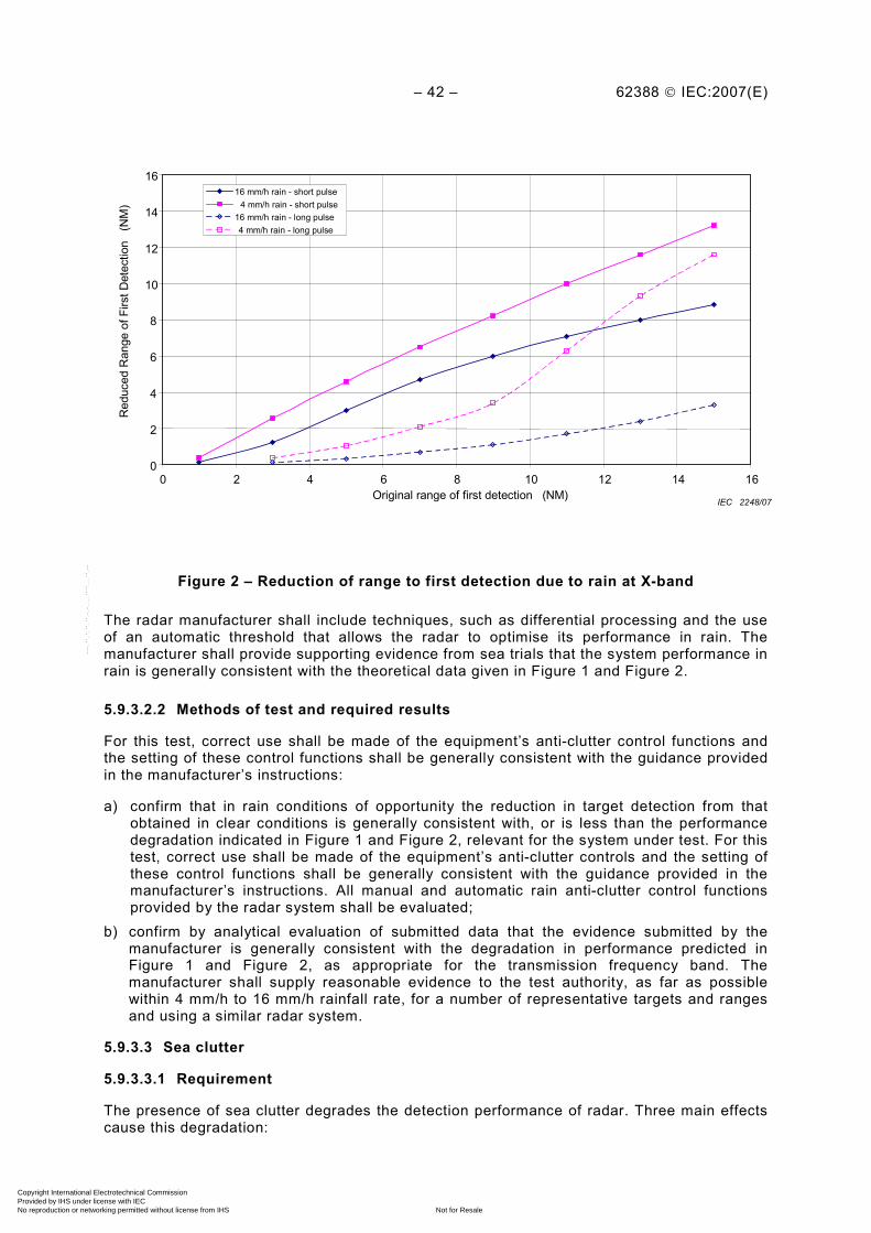
– 42 – 62388 © IEC:2007(E)
0
2
4
6
8
10
12
14
16
0 2 4 6 8 10 12 14 16Original range of first detection (NM)
Red
uced
Ran
ge o
f Firs
t Det
ectio
n (
NM
)
16 mm/h rain - short pulse 4 mm/h rain - short pulse
16 mm/h rain - long pulse 4 mm/h rain - long pulse
IEC 2248/07
Figure 2 – Reduction of range to first detection due to rain at X-band
The radar manufacturer shall include techniques, such as differential processing and the use of an automatic threshold that allows the radar to optimise its performance in rain. The manufacturer shall provide supporting evidence from sea trials that the system performance in rain is generally consistent with the theoretical data given in Figure 1 and Figure 2.
5.9.3.2.2 Methods of test and required results
For this test, correct use shall be made of the equipment’s anti-clutter control functions and the setting of these control functions shall be generally consistent with the guidance provided in the manufacturer’s instructions:
a) confirm that in rain conditions of opportunity the reduction in target detection from that obtained in clear conditions is generally consistent with, or is less than the performance degradation indicated in Figure 1 and Figure 2, relevant for the system under test. For this test, correct use shall be made of the equipment’s anti-clutter controls and the setting of these control functions shall be generally consistent with the guidance provided in the manufacturer’s instructions. All manual and automatic rain anti-clutter control functions provided by the radar system shall be evaluated;
b) confirm by analytical evaluation of submitted data that the evidence submitted by the manufacturer is generally consistent with the degradation in performance predicted in Figure 1 and Figure 2, as appropriate for the transmission frequency band. The manufacturer shall supply reasonable evidence to the test authority, as far as possible within 4 mm/h to 16 mm/h rainfall rate, for a number of representative targets and ranges and using a similar radar system.
5.9.3.3 Sea clutter
5.9.3.3.1 Requirement
The presence of sea clutter degrades the detection performance of radar. Three main effects cause this degradation:
Copyright International Electrotechnical Commission Provided by IHS under license with IEC
Not for ResaleNo reproduction or networking permitted without license from IHS
--`,,```,,,,````-`-`,,`,,`,`,,`---
62388 © IEC:2007(E) – 43 –
a) large waves can obscure targets. There is no generally applicable and reliable way of overcoming this effect;
b) waves reflect radar energy that competes with the reflection from the target. This increases the noise levels that the target is embedded within. However, the statistical nature of the wave-reflected signal differs from that of the target and various combinations of signal processing techniques can help to make the target more visible;
c) some waves can exist over several scans and during this time exhibit a target-like behaviour. This causes sea ‘spikes’ that can obscure or be confused with real targets. Appropriate signal processing can sometimes reduce this effect but not consistently.
As far as possible, tests shall be made when the targets are upwind from the radar antenna position. Crosswinds and downwind will improve target detection; in this case, the test results may exceed the minimum requirement. Deviations from the direction of the wind related to the antenna position shall be noted in the test report.
At longer distances, typically over a mile or two (depending for example on antenna height), the effect of b) above is greatly lessened. At shorter distances, this effect becomes very marked and the radar manufacturer shall include signal processing in order to improve the detection performance of the radar in conditions of sea clutter caused by this effect. This needs to include the provision of a manual control and an automatic anti-clutter control that affect the threshold and the range dependence of the threshold (Sensitivity Time Control).
The manufacturer shall include processing to enable optimisation of the performance of the radar for effects caused by b) and c) above.
Signal processing, for example scan-to-scan correlation, can reduce the effect of c) above. The manufacturer should include a means to apply such techniques in order to reduce the effect. Side effects of this technique such as limitations in the detection of fast targets shall be noted in the user manual.
5.9.3.3.2 Methods of test and required results
The methods of test and the required results are as follows:
a) confirm by observation and evaluation that the following performance is achieved under the defined test conditions:
• tests shall be performed in different sea states of opportunity between 2 and 5. At least one test shall be performed in sea state 3 or greater. Tests at the higher level of sea states are more significant and should be used whenever possible. The sea state used when commencing the test shall be noted in the test report. The nominal height of the radar antenna should be set to 15 m above actual sea height. The nominal height of the test radar target should be set to 3,5 m above actual sea level;
• the nominal range of the test targets shall be at 0,4 NM for S-band and at 0,7 NM for X-band systems. Three radar test targets with characteristics equivalent to an omni-azimuth (horizontal plane) Luneberg lens reflector shall be used. The radar cross-section of the three reflectors at the frequency of measurement shall be 1 m
2, 5 m
2 and
10 m2 for X-band and 0,1 m
2, 0,5 m
2 and 1 m
2 for S-band.
NOTE To achieve a consistent target performance, an omni-azimuth (horizontal plane) lens reflector (featuring a metal grid reflector to provide a stable and a consistent RCS) is recommended for the test targets. The design is based on a dielectric sphere with a permittivity varying with the distance from the centre, providing a focal point located at the peripheral of the lens. Alternative reflectors that can maintain the same tolerance of ± 2,0 dB on the radar cross-section, over 360° in azimuth and ± 15° elevation, may also be used. The reflector gives a wide response, wide bandwidth and compact size. The tight tolerances of this reflector make it suitable as a benchmark target. Standard octahedral radar reflectors and other Luneberg lenses are not suitable.
The test shall be set up to ensure that there is confidence that all measurements will be taken at the peak of the multi-path pattern (see Annex D). Minor adjustments in the antenna height and target range/height figures given above may need to be made for each set of
Copyright International Electrotechnical Commission Provided by IHS under license with IEC
Not for ResaleNo reproduction or networking permitted without license from IHS
--`,,```,,,,````-`-`,,`,,`,`,,`---
– 44 – 62388 © IEC:2007(E)
measurements (observation period) to ensure that the measurements continue to be made at the multi-path peak.
With the radar set at the 6 NM range, with no precipitation within this range and with no sea or rain clutter processing applied, the radar gain control function shall be set so that there is a light noise speckle at longer ranges, outside the range where sea clutter is visible (at this stage there could be significant sea clutter visible at shorter ranges). The range scale shall then be set to 3 NM and the manual sea clutter control function adjusted to make the target optimally visible in a light clutter speckle. Test targets shall be continuously optically visible during these tests.
b) confirm by observation that the manufacturer has included processing to enable optimisation of the performance of the radar for effects (see 5.9.3.3.1);
c) confirm by observation that a skilled user can adjust the manual anti-clutter control function to reduce the visible level of sea clutter around the target for the best target visibility. Ensure that the target is visible to a skilled user and is assessed to be generally consistent with Table 3 and Table 4, with visibility for at least 80 % of scans (tabulated as V) or at least 50 % of scans (tabulated as M) as appropriate for the sea state and target radar cross-section.
In these tests, no allowance has been made for wave obscuration. If significant wave obscuration is present, the results will need to be interpreted accordingly.
NOTE Performance predictions are only indicative of the performance achieved in the real world and hence are only provided for guidance.
Each visibility test shall be conducted over at least twenty scans and once set for the observation period the anti-clutter control functions shall not be readjusted. The test shall be repeated for a minimum of three times and the calculated average Pd shall be recorded. For marginal pass/fail results, this procedure shall be repeated for at least 5 times for each sea state measured. To aid a marginal pass/fail decision, results may be assessed by bracketing results gained from two different reflector sizes, for example a 1 m
2 and a 5 m
2 target. The
target visibility test results, the description of the environment and the test location shall be recorded.
d) confirm by observation that the automatic anti-clutter control functions are effective in improving target visibility when following the manufacturer’s defined procedures;
e) confirm by analytical evaluation that the radar manufacturer has submitted recorded evidence from trials conducted in a variety of sea clutter conditions and that the supplied sea clutter control functions are effective in improving target visibility;
f) confirm by observation that limitations such as the detection of fast vessels when scan to scan techniques are used are noted in the user manual.
5.9.3.4 Performance in sea and rain clutter
5.9.3.4.1 Requirement
Control functions supplied by the manufacturer for optimising radar performance in sea and rain clutter shall also be effective in conditions that have a mixture of both types of clutter. In these conditions, detection performance will be further degraded.
5.9.3.4.2 Methods of test and required results
The methods of test and the required results are as follows:
a) confirm by observation that in conditions of opportunity the clutter controls can be set to improve target visibility when there is both rain and sea clutter present. Ensure that the performance is generally consistent with the tests undertaken separately for rain and sea clutter (see 5.9.3.2.2 and 5.9.3.3.2);
b) confirm by observation that the automatic anti-clutter control functions improve target visibility in general accordance with the manufacturer’s documentation and that the
Copyright International Electrotechnical Commission Provided by IHS under license with IEC
Not for ResaleNo reproduction or networking permitted without license from IHS
--`,,```,,,,````-`-`,,`,,`,`,,`---
62388 © IEC:2007(E) – 45 –
performance is generally consistent with the tests undertaken separately for rain and sea clutter (see 5.9.3.2.2 and 5.9.3.3.2).
NOTE These tests need not be conducted if the manufacturer has provided sufficient evidence of performance in combined sea and rain conditions.
Table 3 – X-band pass/fail assessment criteria
Target visibility in Douglas sea states X-band test target RCS:
SS 1 to 2 SS 2 to 3 SS 3 to 4 SS 4 to 5
1 m2 V-M M-NV
5 m2 V V-M M-NV
10 m2 V V V V-M
NOTE Test target range is nominally positioned at 0,7 NM.
Table 4 – S-band pass/fail assessment criteria
Target visibility in Douglas sea states S-band test target RCS:
SS 1 to 2 SS 2 to 3 SS 3 to 4 SS 4 to 5
0,1 m2 V V-M M-NV
0,5 m2 V V V-M M-NV
1,0 m2 V V V V-M
NOTE Test target range is nominally positioned at 0,4 NM.
Table 5 – Pass/fail assessment
Abbreviation Interpretation
SS Sea state
V Target visible for at least 80 %
M Target visible for at least 50 %
NV Target visible for less than 50 %
NOTE Results are derived by averaging the Pd for all observations in each condition.
NOTE Detailed numerical data supporting the defined test criteria is shown in Annex D.
NOTE Full detection performance predictions are tabulated in Annex D.
Copyright International Electrotechnical Commission Provided by IHS under license with IEC
Not for ResaleNo reproduction or networking permitted without license from IHS
--`,,```,,,,````-`-`,,`,,`,`,,`---

– 46 – 62388 © IEC:2007(E)
Table 6 – Douglas sea state parameters
Douglas sea state Mean wind speed
kn
Significant wave height
m
Sea state description
0 <4 <0,2 Flat, very calm
1 5-7 0,6 Smooth
2 7-11 0,9 Slight
3 12-16 1,2 Moderate
4 17-19 2,0 Rough
5 20-25 3,0 Very rough
6 26-33 4,0 High
NOTE Significant wave height is defined as the average height (crest to trough) of the one-third highest waves. Individual waves and/or swell can combine to significantly increase the wave height and may result in obscuration of the target. This table only applies to waves formed by local wind.
NOTE The table values are approximate due to the subjective nature of the sea state assessment.
NOTE Sea swell will make assessment of wave height very difficult.
5.9.4 Radar performance documentation
5.9.4.1 Requirement
(MSC.192/5.3.1.3.5) Degradation due to a long transmission line, antenna height or any other factors shall be clearly stated in the user manual.
Relevant factors shall also be included in the installation instructions.
The radar manufacturer shall include in the user manual a description of the effects that reduce the performance of the radar in sea clutter and emphasise that in increasing levels of sea clutter some targets will become difficult or impossible to detect. A description of how the detection of targets in sea clutter can be optimised shall be given.
The user manual shall include the relevant data and operational techniques for optimising performance relating to Figure 1 and Figure 2 (degradation of performance in rain). Documentation shall include a description of the degradation of radar performance in rain in a manner that would be understood by the user.
5.9.4.2 Methods of test and required results
The methods of test and the required results are as follows:
a) confirm by document inspection that factors which could degrade radar performance are described in the user manual;
b) confirm by document inspection that installation-related factors which could degrade radar performance are described in the installation manual;
c) confirm by document inspection that the manufacturer has included techniques for optimising the performance of the radar in rain to achieve, as a minimum, performance generally consistent with Figure 1 and Figure 2, as appropriate;
d) confirm by document inspection that the user manual includes relevant data relating to Figure 1 and Figure 2 and that there is a description of the degradation of radar performance in rain in a manner that would be understood by the user;
e) confirm by document inspection that the user manual provides a description of the effects that reduce the performance of the radar in sea clutter and emphasises that in increasing levels of sea clutter, some targets will become difficult or impossible to detect. A
Copyright International Electrotechnical Commission Provided by IHS under license with IEC
Not for ResaleNo reproduction or networking permitted without license from IHS
--`,,```,,,,````-`-`,,`,,`,`,,`---
62388 © IEC:2007(E) – 47 –
description of how the detection of targets in sea clutter can be optimised shall be provided;
f) confirm by document inspection that the user manual has a description of the effects that sea clutter has on the detection performance of radar (see 5.9.3.3.1) and that a description is given of the equipment control functions and of the recommended user procedures to reduce the effects of clutter. The documentation shall include a warning on the limitation of such controls and that wanted targets may remain or become invisible. In particular, unless the manufacturer can show otherwise, it should be stated that the use of control functions to reduce sea clutter spikes may make some targets invisible, particularly targets with higher speeds;
g) confirm by document inspection that the user manual explains that further degradation in detection performance will be experienced when the radar is operating in simultaneous conditions of precipitation and sea clutter;
h) confirm by document inspection that the radar manufacturer has submitted sufficient evidence from tests conducted in a variety of combined sea and rain clutter conditions.
5.10 Radar antenna (including pitch and roll)
5.10.1 General
The radar antenna is fundamental to the radar performance and shall be tested to provide information for specific tests required within this standard.
5.10.2 Vertical radiation pattern/pitch and roll
5.10.2.1 Requirement
(MSC.192/5.6) The target detection performance of the equipment shall not be substantially impaired when own ship is rolling or pitching up to ± 10°.
The vertical radiation pattern shall be designed to permit the pitch and roll of a ship without undue loss of performance, while providing a main beam pattern to limit degradation in performance due to nearby structures and to reduce the illumination of precipitation.
5.10.2.2 Methods of test and required results
The methods of test and the required results are as follows:
a) confirm by measurement, the vertical radiation pattern (one way) of the radar antenna, measured either in the far field region or in a region that can be referenced to it. The measurement shall be carried out at the upper and lower frequency band declared by the manufacturer. The vertical plots shall be recorded;
b) confirm by document inspection of the measured result in a), that the –3 dB beam width encompasses ± 10° in elevation. Compliance for alternative tests for meeting the above requirements may be demonstrated by measurements of the antenna radiation pattern and submission of processing tests for achieving the required results. Providing that the radar system meets with the roll/pitch requirements of 5.10, alternative processing may be used to permit a broader vertical antenna beam width.
5.10.3 Antenna horizontal pattern
5.10.3.1 Requirement
The X-band radar shall be capable of operating in a horizontally polarised mode. The far field horizontal pattern for an X-band antenna shall be measured at the upper and lower operational frequencies, as specified by the manufacturer. The measurements provide a performance check at the frequency extremes. The limits of the horizontal beam pattern specified in Table 7 shall be met. The figures relate to one way propagation. The limits in Table 7 shall also apply to an S-band antenna.
Copyright International Electrotechnical Commission Provided by IHS under license with IEC
Not for ResaleNo reproduction or networking permitted without license from IHS
--`,,```,,,,````-`-`,,`,,`,`,,`---
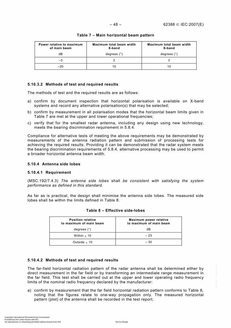
– 48 – 62388 © IEC:2007(E)
Table 7 – Main horizontal beam pattern
Power relative to maximum of main beam
dB
Maximum total beam width X-band
degrees (°)
Maximum total beam width S-band
degrees (°)
–3 2 2
–20 10 10
5.10.3.2 Methods of test and required results
The methods of test and the required results are as follows:
a) confirm by document inspection that horizontal polarisation is available on X-band systems and record any alternative polarisation(s) that may be selected;
b) confirm by measurement in all polarisation modes that the horizontal beam limits given in Table 7 are met at the upper and lower operational frequencies;
c) verify that for the smallest radar antenna, including any design using new technology, meets the bearing discrimination requirement in 5.8.4.
Compliance for alternative tests of meeting the above requirements may be demonstrated by measurements of the antenna radiation pattern and submission of processing tests for achieving the required results. Providing it can be demonstrated that the radar system meets the bearing discrimination requirements of 5.8.4, alternative processing may be used to permit a broader horizontal antenna beam width.
5.10.4 Antenna side lobes
5.10.4.1 Requirement
(MSC.192/7.4.3) The antenna side lobes shall be consistent with satisfying the system performance as defined in this standard.
As far as is practical, the design shall minimise the antenna side lobes. The measured side lobes shall be within the limits defined in Table 8.
Table 8 – Effective side-lobes
Position relative to maximum of main beam
degrees (°)
Maximum power relative to maximum of main beam
dB
Within ± 10 – 23
Outside ± 10 – 30
5.10.4.2 Methods of test and required results
The far-field horizontal radiation pattern of the radar antenna shall be determined either by direct measurement in the far field or by transforming an intermediate range measurement in the far field. This test shall be carried out at the upper and lower operating radio frequency limits of the nominal radio frequency declared by the manufacturer:
a) confirm by measurement that the far field horizontal radiation pattern conforms to Table 8, noting that the figures relate to one-way propagation only. The measured horizontal pattern (plot) of the antenna shall be recorded in the test report;
Copyright International Electrotechnical Commission Provided by IHS under license with IEC
Not for ResaleNo reproduction or networking permitted without license from IHS
--`,,```,,,,````-`-`,,`,,`,`,,`---
62388 © IEC:2007(E) – 49 –
b) confirm by analytical evaluation that no significant side lobes exceed the limits defined in Table 8. The antenna horizontal radiation pattern shows the relative response of the antenna plotted against angular displacement in the horizontal plane. A significant side-lobe is defined as any positive excursion from the monotonically decreasing main beam pattern of more than 2 dB.
5.11 Radar availability
5.11.1 Standby and transmit
5.11.1.1 Requirement
(MSC.192/5.8) The radar equipment shall be fully operational (run or transmit status) within 4 minutes after switch-on from cold. A standby condition shall be provided, in which there is no operational radar transmission. The radar shall be fully operational within 5 s from the standby condition.
5.11.1.2 Methods of test and required results
The methods of test and the required results are as follows:
a) confirm by observation that a standby facility is provided; b) confirm by measurement that the 4 min operational requirement from switch-on is met.
The radar system shall be pre-conditioned by being disconnected from the power source for at least 1 h, then reconnected to a power source, switched on and a stopwatch started. As soon as the radar system indicates that it is available for operation, it shall be set to transmit mode. When the radar system is fully operational, the stop watch shall be stopped and the time recorded. The time from switch-on shall be within 4 minutes;
c) confirm by measurement that the 5 s operational requirement from standby is met. The radar system shall be set to the standby mode for at least 2 minutes, after which the radar system shall be set to transmit and the stopwatch started. When the radar system is fully operational (run or transmit status), the stopwatch shall be stopped and the elapsed time recorded.
6 Display presentation
6.1 General
This standard includes the harmonisation requirements of the presentation of navigational information adopted by the IMO in Resolution MSC.191(79). Exceptions to presentation requirements of Resolution MSC.191(79) are identified.
NOTE The manufacturer may submit evidence of physical display measurements and related documentation to the satisfaction of the test authorities to support the physical requirements. In this case and with the agreement of the test authority, additional measurements during the performance test may not be deemed necessary.
6.2 Performance standards
(MSC.192(6.2.1) The display presentation shall comply with the performance standards for the Presentation of Navigation-related Information on Shipborne Navigational Displays (MSC.191(79)), unless otherwise specified in this standard to maintain the clarity of the radar image.
Tests in Clause 6 verify compliance with the radar presentation requirements of MSC.191(79).
NOTE A future IEC test standard may further clarify the presentation requirements and methods of test.
Copyright International Electrotechnical Commission Provided by IHS under license with IEC
Not for ResaleNo reproduction or networking permitted without license from IHS
--`,,```,,,,````-`-`,,`,,`,`,,`---
– 50 – 62388 © IEC:2007(E)
6.3 Presentation of information
6.3.1 Consistency of layout
6.3.1.1 Requirement
(MSC.191/5.1.1) The presentation of alphanumeric data, information, and text and icons shall be consistent within the user interface with respect to screen layout and arrangement of information (for example from screen to screen and from page to page).
Data and control functions shall be logically grouped according to the task-at-hand. Priority information essential to the task-at-hand shall be identified for each application, permanently or persistently displayed and presented to the user, as appropriate for the application, in a prominent manner by, for example, use of position, size and colour.
6.3.1.2 Methods of test and required results
The methods of test and the required results are as follows:
a) verify that the screen layout and arrangement of alphanumeric data information and text is consistent in accordance with Annex I and IEC 60945, Clause 4;
b) confirm by analytical evaluation that alphanumeric data, information and text is uniformly located within the user interface from screen to screen and page to page, as far as practical, according to either the function or the task at hand;
c) verify that data and controls are logically grouped according to either their function or the task-at-hand in accordance with Annex I and IEC 60945, Clause 4;
d) confirm by analytical evaluation that information essential to the task-at-hand is distinguishable from other information (for example by location, size, colour) and is permanently displayed as appropriate for each application.
6.3.2 Consistency of presentation
6.3.2.1 Requirement
(MSC.191/5.1.2) The presentation of alphanumeric data, information and text shall be consistent with respect to numerical values, units, meaning, sources, validity and integrity (if available).
6.3.2.2 Methods of test and required results General compliance for the consistency of presentation is verified in IEC 60945, Clause 4 as applicable.
The methods of test and the required results are as follows:
a) confirm by observation that alphanumeric data, information and text is readable under all ambient light conditions likely to be experienced on the bridge of a ship (day, dusk and night as defined in IEC 61174);
b) confirm by observation that numerical values (for example for position, speed, distance, time) are presented in a consistent manner;
c) confirm by observation that the presentation of units conforms to SN/Circ.243; d) where the meaning of information is extracted from terms or abbreviations in the
presentation, confirm by observation that the terms and abbreviations used conform to SN/Circ.243;
e) where the source of information is extracted from terms or abbreviations in the presentation, confirm by observation that the terms and abbreviations used conform to SN/Circ.243.
Copyright International Electrotechnical Commission Provided by IHS under license with IEC
Not for ResaleNo reproduction or networking permitted without license from IHS
--`,,```,,,,````-`-`,,`,,`,`,,`---

62388 © IEC:2007(E) – 51 –
6.3.3 Separation of operational display area
6.3.3.1 Requirement
(MSC.191/5.1.3) The presentation of alphanumeric data, information and text shall be clearly separated into an operational display area (for example radar, chart) and one or more user dialogue areas (for example, menus, data, control functions).
Circular, square or rectangular presentations are permitted.
6.3.3.2 Method of test and required results
Confirm by observation that user dialogue areas are clearly separated from the operational display area.
6.3.4 Operational display area information
6.3.4.1 Requirement
(MSC.191/7.1.5) No part of the operational display area shall be permanently used for the presentation of information that is not part of the navigation presentation (for example, pop up displays, drop down menus and information windows). Temporary, limited and relevant target data, information and text may be displayed adjacent to a selected symbol, graphic or target within the operational display area.
6.3.4.2 Methods of test and required results
The methods of test and the required results are as follows:
a) confirm by observation that any information that is not part of the navigation presentation but is superimposed on the operational display area, is presented only in response to an explicit user action (for example a menu selection, hyperlink, hot key, etc.);
b) confirm by observation that any windows containing, for example text, diagrams, etc., superimposed on the operational area, are moveable within the operational area;
c) confirm by observation that any windows containing text, diagrams, etc, superimposed on the operational area are removable from the display.
6.4 Readability
6.4.1 Readability under all ambient light conditions
6.4.1.1 Requirement
(MSC.191/5.2.1) The presentation of alphanumeric data, information and text, symbols and other graphical information (for example radar image or echoes) shall support readability from typical user positions (i.e. reading distance and viewing angles) under all ambient light conditions, (day, dusk and night), likely to be experienced on the bridge of a ship, and with due consideration to the night vision of the officer of the watch.
NOTE The day colour table specified in IHO ECDIS Presentation Library Ed. 3.3 uses a white background that may not support readability under all light conditions and may be a risk to safety of navigation for some navigational systems and equipment including radar. Readability may be achieved by using the black background in the dusk or night colour tables specified in IHO ECDIS Presentation Library Ed. 3.3, or the day black background colour table specified in IHO ECDIS Presentation Library Ed. 3.2, and adjusting brightness and contrast, if provided, for use under all light conditions.
Copyright International Electrotechnical Commission Provided by IHS under license with IEC
Not for ResaleNo reproduction or networking permitted without license from IHS
--`,,```,,,,````-`-`,,`,,`,`,,`---
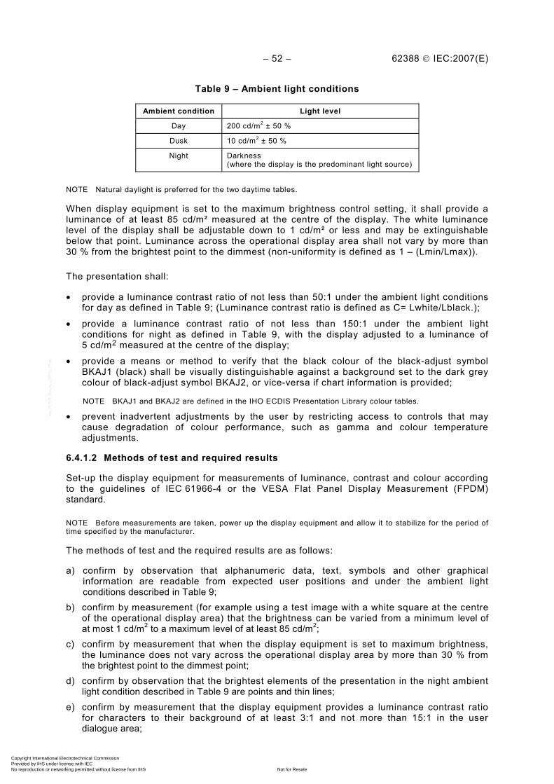
– 52 – 62388 © IEC:2007(E)
Table 9 – Ambient light conditions
Ambient condition Light level
Day 200 cd/m2 ± 50 %
Dusk 10 cd/m2 ± 50 %
Night Darkness (where the display is the predominant light source)
NOTE Natural daylight is preferred for the two daytime tables.
When display equipment is set to the maximum brightness control setting, it shall provide a luminance of at least 85 cd/m² measured at the centre of the display. The white luminance level of the display shall be adjustable down to 1 cd/m² or less and may be extinguishable below that point. Luminance across the operational display area shall not vary by more than 30 % from the brightest point to the dimmest (non-uniformity is defined as 1 – (Lmin/Lmax)).
The presentation shall:
• provide a luminance contrast ratio of not less than 50:1 under the ambient light conditions for day as defined in Table 9; (Luminance contrast ratio is defined as C= Lwhite/Lblack.);
• provide a luminance contrast ratio of not less than 150:1 under the ambient light conditions for night as defined in Table 9, with the display adjusted to a luminance of 5 cd/m2 measured at the centre of the display;
• provide a means or method to verify that the black colour of the black-adjust symbol BKAJ1 (black) shall be visually distinguishable against a background set to the dark grey colour of black-adjust symbol BKAJ2, or vice-versa if chart information is provided;
NOTE BKAJ1 and BKAJ2 are defined in the IHO ECDIS Presentation Library colour tables.
• prevent inadvertent adjustments by the user by restricting access to controls that may cause degradation of colour performance, such as gamma and colour temperature adjustments.
6.4.1.2 Methods of test and required results
Set-up the display equipment for measurements of luminance, contrast and colour according to the guidelines of IEC 61966-4 or the VESA Flat Panel Display Measurement (FPDM) standard.
NOTE Before measurements are taken, power up the display equipment and allow it to stabilize for the period of time specified by the manufacturer.
The methods of test and the required results are as follows:
a) confirm by observation that alphanumeric data, text, symbols and other graphical information are readable from expected user positions and under the ambient light conditions described in Table 9;
b) confirm by measurement (for example using a test image with a white square at the centre of the operational display area) that the brightness can be varied from a minimum level of at most 1 cd/m2 to a maximum level of at least 85 cd/m2;
c) confirm by measurement that when the display equipment is set to maximum brightness, the luminance does not vary across the operational display area by more than 30 % from the brightest point to the dimmest point;
d) confirm by observation that the brightest elements of the presentation in the night ambient light condition described in Table 9 are points and thin lines;
e) confirm by measurement that the display equipment provides a luminance contrast ratio for characters to their background of at least 3:1 and not more than 15:1 in the user dialogue area;
Copyright International Electrotechnical Commission Provided by IHS under license with IEC
Not for ResaleNo reproduction or networking permitted without license from IHS
--`,,```,,,,````-`-`,,`,,`,`,,`---

62388 © IEC:2007(E) – 53 –
f) confirm by measurement that the display equipment provides a maximum luminance value for the colour black of 0,52 cd/m2 under the day ambient light condition described in Table 9;
g) where display equipment is intended to present symbols for either operational or charted information, confirm by measurement that it provides a luminance contrast ratio of not less than: 1) 50:1 at the centre of the display under the day ambient light condition described in
Table 9; 2) 10:1 at ±80° horizontal and ±60° vertical on the display under the day ambient light
condition described in Table 9; 3) 150:1 at the centre of the display under the night ambient light condition described in
Table 9; 4) 150:1 at ±20° horizontal and ±15° vertical on the display under the night ambient light
condition described in Table 9; h) where display equipment is intended to present symbols for charted information:
1) confirm by observation that the user can verify that the colour black is visually distinguishable against a background set to dark grey, and vice-versa;
2) confirm by measurement at ±60° horizontal and ±30° vertical that the colour shift is not more than 0,03 in the CIE 1976 coordinate system.
6.4.2 Legibility of alphanumeric data, information and text
6.4.2.1 Requirement
(MSC.191/5.2.2) Alphanumeric data, information and text shall be presented using a clearly legible non-italic, sans-serif font. The font size shall be appropriate for the viewing distance from user positions likely to be experienced on the bridge of a ship. The manufacturer’s documentation shall identify the nominal viewing distance for the display equipment.
Alphanumeric data, information and text shall be readable under all ambient light conditions likely to be experienced on the bridge of a ship.
For text, the character height in millimetres shall be not less than 3,5 times the nominal viewing distance in metres and shall be not less than 11 pixels (see ISO 9241-8, IEC 60945 and IHO S-52, Appendix 2).
6.4.2.2 Methods of test and required results
The methods of test and the required results are as follows:
a) confirm by observation that alphanumeric data, information and text are presented using non-italic, sans-serif font format;
b) verify that the alphanumeric data, information and text complies with the requirements of IEC 60945, Clause 4. Compliance shall be assessed for the user positions identified in the manufacturer's documentation;
c) confirm by measurement that text height, the distance between the top and bottom edges of the smallest capital letter used on the screen, complies with the minimum size requirement for the nominal viewing distance stated in the manufacturer’s documentation (3,5 mm per metre of viewing distance and at least 11 pixels);
d) while the display is off, adjust the ambient light level reflected from white paper positioned on the display screen to each of the values in Table 9. In each case, confirm by observation that alphanumeric data, information and text are readable.
Copyright International Electrotechnical Commission Provided by IHS under license with IEC
Not for ResaleNo reproduction or networking permitted without license from IHS
--`,,```,,,,````-`-`,,`,,`,`,,`---
– 54 – 62388 © IEC:2007(E)
6.4.3 Presentation of text
6.4.3.1 Requirement
(MSC.191/5.2.3) Text shall be presented using simple unambiguous language that is easy to understand. Navigational terms and abbreviations shall be presented using the nomenclature defined in IMO SN/Circ.243.
6.4.3.2 Methods of test and required results
The methods of test and the required results are as follows:
a) confirm by observation that text is presented using standard marine terminology (see SN/Circ.243, Annex 2) or using text that provides clear meaning by its context;
b) confirm by observation that navigational terms and abbreviations are presented using the nomenclature in SN/Circ.243.
6.4.4 Icons
6.4.4.1 Requirement
(MSC.191/5.2.4) When icons are used, their purpose shall be intuitively recognized (i.e. in accordance with the expectations of the users) by appearance, placement, and grouping in accordance with Annex I.
6.4.4.2 Methods of test and required results
The methods of test and the required results are as follows:
a) confirm by observation that icons used for common function controls conform to Annex I; b) confirm by analytical evaluation that icons used for other purposes conform to principles
and guidelines of ISO 80416-4 or an equivalent accepted standard; c) confirm by inspection of documentation that all icons are identified in the system or in the
manufacturer’s documentation.
6.5 Colours and intensity
6.5.1 Use and discrimination of colour
6.5.1.1 Requirement
(MSC.191/5.3.1) The colours used for the presentation of alphanumeric data, text, symbols and other graphical information shall provide sufficient contrast for discrimination and identification against the background under all ambient lighting conditions (day, dusk and night) likely to be experienced on the bridge of a ship.
(MSC.191/5.3.2) The colours and brightness shall take into account the light conditions of daylight, dusk and night. The presentation shall support night viewing by showing light foreground information on a dark non-reflecting background at night.
(MSC.191/5.3.3) The background colour and contrast shall be chosen to allow presented information to be easily discriminated without degrading the colour coding aspects of the presentation.
(MSC.191/8.3.1) Multicoloured display equipment shall be used.
(MSC.191/8.3.2) Multicoloured operational displays, including multifunctional displays (for example, Chart Radar or Conning displays) should provide a minimum of 64 colours.
Copyright International Electrotechnical Commission Provided by IHS under license with IEC
Not for ResaleNo reproduction or networking permitted without license from IHS
--`,,```,,,,````-`-`,,`,,`,`,,`---

62388 © IEC:2007(E) – 55 –
If the display equipment is not intended to support the presentation of charted information then the colours used should be based upon the colours defined for the symbols and radar maps, where defined, in Annex J, along with a range of shades based upon the following colours - white, grey, black, blue, magenta, green, yellow, orange and red - or a subset of them, provided they are visually distinguishable from each other and identifiable (see also ISO 9241-8.)
The method for colour alignment for a chart radar is given in Annex K.
The presentation for the user dialogue area shall use clearly visible colours which do not detract from the operational display area in the day, dusk and night colour tables, and do not adversely affect the night vision of the officer of the watch. All information shall be presented on a background of high contrast, emitting as little light as possible at night. Under night conditions, the brightest elements of the presentation should be restricted to thin lines and points. Large illuminated areas are discouraged.
6.5.1.2 Methods of test and required results
The methods of test and the required results are as follows:
a) confirm by analytical evaluation that the colours in the user dialogue areas do not detract from the presentation under each ambient light condition (day, dusk and night) as specified in Table 9;
b) if the display equipment is not intended to support the presentation of chart information, confirm by observation that the display equipment is capable of presenting at least the following colours so that they are identifiable under the ambient light conditions defined in 6.5.1.1 white, grey, black, blue, magenta, green, yellow, orange and red, and that the colours are used as noted in Clause J.5 for radar maps;
c) confirm by analytical evaluation that in the night ambient condition, the user dialogue area minimizes the use of illuminated areas and bright lines, presents illuminated text on a dark background and, as a whole, does not emit more light than the operational display area;
d) confirm by observation of the user dialogue areas that the presentation meets the following criteria against all background colours for each ambient light condition; day, dusk and night (as defined in IEC 61174): – the text and graphics appear clear and sharp; – the colours used are suitable for the application and do not distract from the
information presented in the operational area; – in the night condition, the general luminance of the user dialogue area does not
exceed the luminance of the operational display area; e) verify that colours and intensity are in accordance with the requirements of 6.5.1.1 where
these are applicable to text, symbols and graphics; f) verify that the background contrast is in accordance with the requirements of IEC 60945,
Clause 4 in the conditions of day, dusk and night; g) confirm by analytical evaluation of alternative colour differentiation tables for day, dusk
and night conditions provided by the manufacturer, that those foreground colours used for navigational symbols which deviate from any recommended colours within Annex J for navigational symbols meet the operational requirements;
h) if the equipment is specified as a chart radar, the documentation shall confirm that a minimum of 64 colours are available (see 6.12);
i) confirm that the use of colour is in accordance with the considerations listed in Clause J.4.
Copyright International Electrotechnical Commission Provided by IHS under license with IEC
Not for ResaleNo reproduction or networking permitted without license from IHS
--`,,```,,,,````-`-`,,`,,`,`,,`---

– 56 – 62388 © IEC:2007(E)
6.6 Symbols
6.6.1 Operational information
6.6.1.1 Requirement
(MSC.191/5.4.1) Symbols used for the presentation of operational information are defined in IMO SN/Circ.243 and further specified in Annex J.
(MSC.191/8.4.6.8) The alphanumeric data shall not obscure graphically presented operational information.
Where accurate colour identification of an isolated symbol is required, the symbol should subtend at least 8,7 mm per metre (30 min of arc) at the nominal viewing distance and shall be not less than 5 mm per metre (17 min of arc) of viewing distance.
NOTE The use of spectrally extreme blue (v’ < 0,2) should be avoided for images subtending less than 34,9 mm per metre (2 ° of arc) of viewing distance (see ISO 9241-8, 6.4).
6.6.1.2 Methods of test and required results
The methods of test and the required results are as follows:
a) confirm that the symbols used for operational information are as defined in Annex J; b) confirm by observation that the alphanumeric data does not obscure graphically presented
information; c) confirm by observation and measurement that when accurate colour identification of an
isolated symbol is required, the symbol subtends the required arc as specified in 6.6.1.1.
6.7 Coding of information
6.7.1 Colour coding of alarm-related information
6.7.1.1 Requirement
(MSC.191/5.5.2) When colour coding is used, the colour red shall be used for coding of alarm related information.
If the video interface or display technology relies on the separate transmission of primary colours, the implementation of the colour red for alarm indications shall not rely solely on the use of the saturated red colour-primary and the presentation of alarms and indications shall be visible and identifiable even after the failure of any one primary colour input to the display.
6.7.1.2 Methods of test and required results
The methods of test and the required results are as follows:
a) confirm by inspection of manufacturer documentation and by observation that red is used for alarm indications;
b) if either the video interface or display technology relies on the separate transmission of primary colours, confirm by observation in each ambient condition that alarms and indications are visible and remain identifiable after the red primary is disabled. Where the disabling of red primary is impractical, the manufacturer shall state that the design complies with this requirement.
6.7.2 Colour coding in combination with other attributes
6.7.2.1 Requirement
(MSC.191/5.5.3) When colour coding is used for coding of alarm related information, it shall be used in combination with other symbol attributes, such as size, shape, and orientation.
Copyright International Electrotechnical Commission Provided by IHS under license with IEC
Not for ResaleNo reproduction or networking permitted without license from IHS
--`,,```,,,,````-`-`,,`,,`,`,,`---

62388 © IEC:2007(E) – 57 –
6.7.2.2 Method of test and required results
Confirm by inspection of the design documentation that colour coding of symbols is always combined with some other attribute.
6.7.3 Flashing of information
6.7.3.1 Requirement
(MSC.191/5.5.4) Flashing of information shall be reserved for unacknowledged alarms.
6.7.3.2 Method of test and required results
Confirm by observation that flashing of information is only used for unacknowledged alarms.
6.8 Integrity marking
6.8.1 Indication of source, validity and integrity status
6.8.1.1 Requirement
(MSC.191/5.6.1) The source, validity, and where possible, the integrity of information shall be indicated. Invalid information or information with low integrity shall be clearly marked qualitatively and/or quantitatively. Invalid information or information with low integrity may be quantitatively indicated (marked) by displaying absolute or percentage values. Examples include:
• source (for example position and velocity from GPS);
• validity (for example validity flag for SDME);
• integrity (for example RAIM or integrity monitoring in DGPS);
• qualitative description (for example colour of text);
• quantitative measures (for example HDOP for GPS).
6.8.1.2 Methods of test and required results
The methods of test and the required results are as follows:
a) confirm by observation that the presentation is capable of indicating the source of information, where applicable;
b) confirm by observation that indications used to identify the source conform to Annex J; c) confirm by observation that the presentation is capable of indicating the validity of
information; d) confirm by inspection of documented evidence that the presentation is capable of
indicating the integrity of information, where applicable. If integrity is indicated quantitatively, confirm by inspection of documented evidence that either absolute values or percentage values are displayed.
6.8.2 Colour coding of validity and integrity
6.8.2.1 Requirement
(MSC.191/5.6.2) When colour coding is used, alphanumeric information with low or doubtful integrity shall be qualitatively marked by using yellow, and invalid information shall be qualitatively marked by using red.
6.8.2.2 Methods of test and required results
The methods of test and the required results are as follows:
Copyright International Electrotechnical Commission Provided by IHS under license with IEC
Not for ResaleNo reproduction or networking permitted without license from IHS
--`,,```,,,,````-`-`,,`,,`,`,,`---
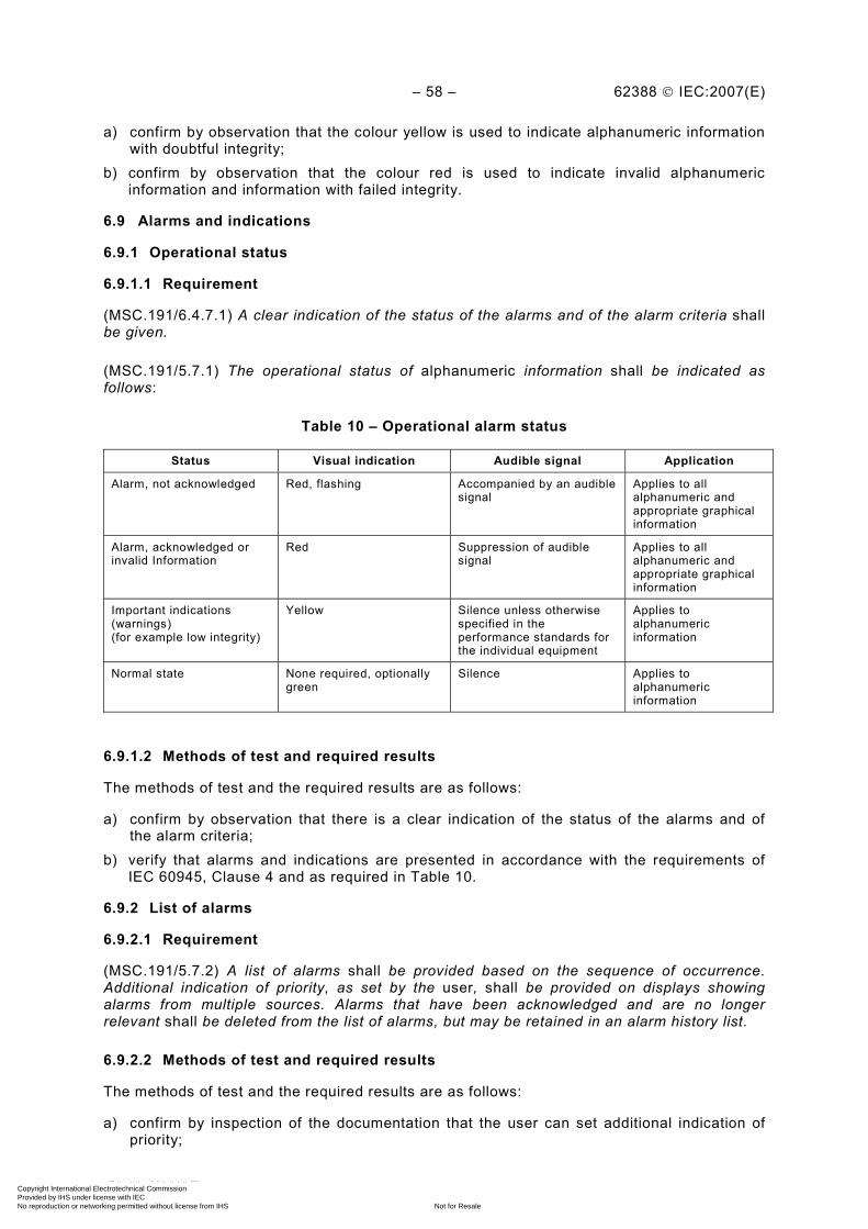
– 58 – 62388 © IEC:2007(E)
a) confirm by observation that the colour yellow is used to indicate alphanumeric information with doubtful integrity;
b) confirm by observation that the colour red is used to indicate invalid alphanumeric information and information with failed integrity.
6.9 Alarms and indications
6.9.1 Operational status
6.9.1.1 Requirement
(MSC.191/6.4.7.1) A clear indication of the status of the alarms and of the alarm criteria shall be given.
(MSC.191/5.7.1) The operational status of alphanumeric information shall be indicated as follows:
Table 10 – Operational alarm status
Status Visual indication Audible signal Application
Alarm, not acknowledged Red, flashing Accompanied by an audible signal
Applies to all alphanumeric and appropriate graphical information
Alarm, acknowledged or invalid Information
Red Suppression of audible signal
Applies to all alphanumeric and appropriate graphical information
Important indications (warnings) (for example low integrity)
Yellow Silence unless otherwise specified in the performance standards for the individual equipment
Applies to alphanumeric information
Normal state None required, optionally green
Silence Applies to alphanumeric information
6.9.1.2 Methods of test and required results
The methods of test and the required results are as follows:
a) confirm by observation that there is a clear indication of the status of the alarms and of the alarm criteria;
b) verify that alarms and indications are presented in accordance with the requirements of IEC 60945, Clause 4 and as required in Table 10.
6.9.2 List of alarms
6.9.2.1 Requirement
(MSC.191/5.7.2) A list of alarms shall be provided based on the sequence of occurrence. Additional indication of priority, as set by the user, shall be provided on displays showing alarms from multiple sources. Alarms that have been acknowledged and are no longer relevant shall be deleted from the list of alarms, but may be retained in an alarm history list.
6.9.2.2 Methods of test and required results
The methods of test and the required results are as follows:
a) confirm by inspection of the documentation that the user can set additional indication of priority;
Copyright International Electrotechnical Commission Provided by IHS under license with IEC
Not for ResaleNo reproduction or networking permitted without license from IHS
--`,,```,,,,````-`-`,,`,,`,`,,`---
62388 © IEC:2007(E) – 59 –
b) confirm by observation that by generation of multiple alarms results in a list of alarms at the display in the correct sequenced order. Confirm by observation that removal of an alarm input will decrease the alarm list accordingly;
c) confirm by observation that acknowledged alarms which are no longer relevant are deleted from the alarm list.
6.9.3 Alarm related information from multiple sources
6.9.3.1 Requirement
(MSC.191/5.7.3) When a single display is used to present information from multiple navigational systems and equipment, the presentation of alarms and indications shall be consistent for the display of:
• the time of alarm occurrence,
• the cause of the alarm,
• the source of the alarm, and
• the status of the alarm (for example, acknowledged, not acknowledged).
NOTE Radar compliant to this standard is required to present information from multiple navigational systems, for example AIS.
6.9.3.2 Method of test and required results
Confirm by observation of the equipment that the presentation of alarm related information from all sources is consistent.
6.10 Presentation of radar information
6.10.1 Radar video images
6.10.1.1 Requirement
(MSC.191/7.2.1.1) The radar video image (echoes), tracked radar targets and reported AIS targets shall not be substantially degraded, masked or obscured by other presented information.
(MSC.191/7.2.1.2) It shall be possible to temporarily suppress all graphical information from the display, retaining only the radar video image and target trails (see also MSC.192/5.14.3).
(MSC.191/7.2.1.3) The brightness of the radar image (echoes) and associated graphic symbols for tracked targets shall be variable. It shall be possible to control the brightness of all displayed radar information. There shall be independent means to adjust the brightness of groups of displayed graphics and alphanumeric data, information and text (for example, tracked radar targets, navigation tools, etc.). The brilliance (brightness) of the heading line shall not be variable to extinction.
(MSC.191/6.3.1) Radar images shall be displayed by using a basic colour that provides optimum contrast against a darker background. A white background shall not be used. Radar echoes shall be clearly visible when presented over a chart background. The relative strength of echoes may be differentiated by tones of the same basic colour. The basic colour may be different for operation under different ambient light conditions (day, dusk and night) likely to be experienced on the bridge of a ship, and with due consideration to the night vision of the officer of the watch. Processed radar information may use additional colours that are not in conflict with other presentation features.
Additional processed images or information that is not a part of the basic radar image may be discriminated from the basic radar image by tones of the basic colour used to present the basic radar image. Alternatively, processed radar information may be differentiated by tones of another basic colour or colours. Additional colours shall provide optimum contrast against a
Copyright International Electrotechnical Commission Provided by IHS under license with IEC
Not for ResaleNo reproduction or networking permitted without license from IHS
--`,,```,,,,````-`-`,,`,,`,`,,`---
– 60 – 62388 © IEC:2007(E)
darker background and shall be clearly visible when presented simultaneously with a chart background (i.e. land, depth areas, etc.) and which do not conflict with other presentation features. The colours may be different for operation under different ambient light conditions (day, dusk and night) likely to be experienced on the bridge of a ship, and with due consideration to the night vision of the officer of the watch.
NOTE The day colour table specified in IHO ECDIS Presentation Library Ed. 3.3 uses a white background that may not support optimum contrast under all light conditions and may be a risk to safety of navigation for some navigational systems and equipment including radar. Optimum contrast may be achieved by using the black background in the dusk or night colour tables specified in IHO ECDIS Presentation Library Ed. 3.3, or the day black background colour table specified in IHO ECDIS Presentation Library Ed. 3.2, and adjusting brightness and contrast, if provided, for use under all light conditions.
If the colour red is used for the radar image, the colour used shall be distinguishable from other uses of the colour red, for example through the use of luminance coding or by different tones of colour.
6.10.1.2 Methods of test and required results
The methods of test and the required results are as follows:
a) confirm by observation that the radar video image (echoes), tracked radar targets and reported AIS targets are not substantially degraded, masked or obscured by other presented information;
b) confirm by observation that the user can suppress the presentation of all graphical information, retaining only the radar image and trails (see also 7.2.3.1);
c) confirm by observation that a means or method to adjust brightness of the radar video is provided;
d) confirm by observation that a separate (independent) means or method to adjust the brightness of tracked radar target symbols is provided;
e) confirm by observation that a separate (independent) means or method to adjust the brightness of groups of other displayed graphics, alphanumeric data, information and text is also provided;
f) verify by observation that the brightness of the heading line (and stern line where presented) cannot be adjusted to the point of extinction (see also 7.2.3 and 7.2.4);
g) confirm by observation that the radar image is presented in contrast on a darker background under all ambient light conditions (day, dusk and night) likely to be experienced on the bridge of a ship;
h) confirm by observation that radar echoes are clearly visible when presented simultaneously with a chart background under all ambient light conditions (day, dusk and night) likely to be experienced on the bridge of a ship.
6.10.2 Linearity and index delay
6.10.2.1 Requirement
(MSC.192/5.9.5) Radar targets shall be displayed on a linear range scale and without a range index delay.
6.10.2.2 Methods of test and required results
The methods of test and the required results are as follows:
a) confirm by observation that the radar targets are displayed on a linear scale and without delay. Confirmation that the range scale is linear may be achieved by the use of calibrated markers or by observing a radar picture based on a known locality;
b) additional and auxiliary radar presentation windows, with or without a range index delay, are permitted outside of the designated operational display area. As far as practical and
Copyright International Electrotechnical Commission Provided by IHS under license with IEC
Not for ResaleNo reproduction or networking permitted without license from IHS
--`,,```,,,,````-`-`,,`,,`,`,,`---
62388 © IEC:2007(E) – 61 –
size permitting, the permitted auxiliary window shall use this radar standard as guidance for functionality and presentation.
6.11 Physical requirements
The provisions of this subclause are applicable to the physical displays associated with navigational systems and equipment on the bridge of a ship, including the stand-alone displays for radar equipment, the multifunction displays used in IBS and INS, and displays supporting composite presentations that integrate information derived from two or more navigational systems or equipment.
Display equipment shall comply with the applicable requirements of IEC 60945 (see 6.3.1.1.).
6.11.1 Operational display area
6.11.1.1 Requirement
(MSC.192/6.2.3) The display sizes shall conform to those defined in Table 1, according to equipment category.
(MSC.191/8.2.1) Display equipment shall be of sufficient size to support the requirements of the relevant IMO performance standards.
(MSC.191/8.2.3) For radar display equipment, the operational display area of the Radar presentation shall be at least a circle of diameter of:
• 180 mm for ships smaller than 500 gross tonnage;
• 250 mm for ships larger than 500 gross tonnage and HSC less than 10 000 gross tonnage;
• 320 mm for ships larger than 10 000 gross tonnage.
The manufacturer’s documentation shall identify the intended size of the operational display area.
6.11.1.2 Method of test and required results
Confirm by measurement that the diameter of the operational display area is at least a circle of diameter of the intended size specified in the manufacturer’s documentation and in Table 1.
6.11.2 Contrast and brightness adjustment
6.11.2.1 Requirement
(MSC.191/8.1.1) It shall be possible to adjust the contrast and brightness of the display provided, as applicable to the display technology. It shall be possible to dim the display. The range of control shall permit the display to be legible under all ambient light conditions likely to be experienced on the bridge of a ship (day, dusk and night). The range of adjustment shall be sufficient to maintain the user’s dark adaptation at night (see 6.4).
(MSC.191/8.1.2) It shall be possible for the navigator or user to reset the values of contrast and/or brightness to a preset or default condition for each of the defined ambient light conditions (day, dusk and night). If the display equipment supports the presentation of charted information, a means or method shall also be provided to return manual control(s) to a reference setting for calibrated colour performance appropriate for each of the colour tables specified in IHO S-52.
The manufacturer’s documentation shall identify the default settings for brightness and contrast controls.
Copyright International Electrotechnical Commission Provided by IHS under license with IEC
Not for ResaleNo reproduction or networking permitted without license from IHS
--`,,```,,,,````-`-`,,`,,`,`,,`---

– 62 – 62388 © IEC:2007(E)
6.11.2.2 Methods of test and required results
The methods of test and the required results are as follows:
a) verify the adjustment of contrast and brightness in accordance with 6.4; b) confirm by observation that a manual brightness control is provided; c) if applicable (for example for CRT technology), confirm by observation that a manual
contrast control is provided; d) confirm by inspection of documented evidence that the manufacturer’s documentation
identifies the default settings for contrast and brightness controls; e) confirm by observation that the default setting for contrast and brightness controls is
identifiable and that the controls can be reset to their default value; f) for equipment intended for display of operational information or charted information,
confirm by measurement of luminance that, for manual user controls such as brightness and contrast, a means or method is provided to return the display to the calibrated operation established by the manufacturer appropriate for each ambient light condition (day, dusk and night) as specified in Table 9.
6.11.3 Temporal stability
6.11.3.1 Requirement
Display equipment shall be perceptually "flicker” free in the direct and peripheral vision at the nominal viewing distance identified in the manufacturer’s documentation under all ambient light conditions likely to be expected on the bridge of a ship (day, dusk, night).
NOTE The perception threshold of “flicker” is known to vary for observers, depending on such factors as age, fatigue, ambient lighting conditions, frequencies, peripheral or direct vision, the displayed image size, image brightness and image content.
6.11.3.2 Methods of test and required results
The methods of test and the required results are as follows:
a) confirm by observation that the display presentation is free of perceived flicker under all ambient light conditions;
b) confirm by inspection of documented evidence whether the response time (luminance persistence) of the display equipment is less than 1 ms;
c) for display equipment based on technologies which have a luminance persistence (response time) much less than 1 ms (for example EL, plasma, LED, etc.), confirm by analytical evaluation that the display equipment emits less energy in the temporal frequencies than an observer will detect as “flicker” according to ISO 13406-2, B.2.6 under each ambient light test condition specified in Table 9;
d) for display equipment with longer luminance persistence (for example CRT, LCD’s, etc.), confirm by analytical evaluation that the display equipment emits less energy in the temporal frequencies than an observer will detect as “flicker” (i.e. the predicted “flicker” threshold) according to ISO 13406-2, B.2.5 under each ambient light test condition specified in Table 9.
6.11.4 Physical controls and status indicators
6.11.4.1 Requirement
Physical controls for display equipment shall be locatable by visual or tactile means. If the display equipment has more than three adjacent control knobs or switches, labels or icons with adjustable illumination shall be provided for identification of these controls. Labels or icons, if provided, shall comply with the readability requirements of 6.4.
Any illuminated status indicators which are separate from the main display (for example built-in to the front panel of the monitor) shall be locatable by visual means. Adjustable illumination
Copyright International Electrotechnical Commission Provided by IHS under license with IEC
Not for ResaleNo reproduction or networking permitted without license from IHS
--`,,```,,,,````-`-`,,`,,`,`,,`---

62388 © IEC:2007(E) – 63 –
provided for labels, icons and status indicators shall be suitable for all ambient light conditions likely to be experienced on the bridge of a ship (day, dusk and night) and considers the need to preserve dark adapted vision.
As a minimum, a switch to power display equipment and visual indications of the presence of input power and video signals shall be provided.
6.11.4.2 Methods of test and required results
The methods of test and the required results are as follows:
a) confirm by observation that physical controls for display equipment are locatable by visual or tactile means;
b) if there are more than three adjacent control knobs or switches, confirm by observation that they have labels or icons with adjustable illumination;
c) confirm by observation that the display equipment can be powered on/off by a physical switch;
d) confirm by observation that a visual indication of the presence of power to the display equipment is provided;
e) confirm by observation that a visual indication of the presence of video signals to the display equipment is provided;
f) if there are illuminated status indicators, confirm by observation that they are locatable by visual means;
g) confirm by observation that adjustable illumination, where provided, is suitable under each of the ambient light conditions defined in Table 9;
h) verify that labels or icons, where provided, meet the requirements of Annex I.
6.12 Colours
6.12.1 Requirement
(MSC.191/8.3.2) Multicoloured operational displays including multifunction displays (for example chart radar displays and conning displays) shall provide a minimum of 64 colours except where permitted or not required by IMO.
6.12.2 Method of test and required results
Confirm by document inspection that the design supports a minimum of 64 colours.
6.13 Screen resolution
6.13.1 Requirement
(MSC.191/8.4) Radar display equipment shall provide a minimum screen resolution of 1280 × 1024 pixels, or equivalent for a different aspect ratio, except where permitted or not required by the IMO. For a 180 mm radar display, a minimum screen resolution of 1024 × 768 pixels, or equivalent for a different aspect ratio, is permitted.
Display equipment intended to support the presentation of charted information shall provide a maximum pixel pitch of 0,29 mm per metre of nominal viewing distance (1 min of arc), for example 0,36 mm at 1237 mm viewing distance. The manufacturer’s documentation shall describe the screen resolution, pixel format and viewing distance (i.e. for measurement of pixel pitch).
6.13.2 Methods of test and required results
The methods of test and the required results are as follows:
Copyright International Electrotechnical Commission Provided by IHS under license with IEC
Not for ResaleNo reproduction or networking permitted without license from IHS
--`,,```,,,,````-`-`,,`,,`,`,,`---
– 64 – 62388 © IEC:2007(E)
a) confirm by inspection of documented evidence that the display equipment supports a screen resolution of at least 1280 x 1024 or equivalent if the equipment uses a different aspect ratio;
b) confirm by inspection of documented evidence that the display equipment provides a maximum pixel pitch of 0,29 mm per metre of nominal viewing distance (1 min of arc);.
c) confirm by inspection of documented evidence that the manufacturer’s documentation identifies the screen resolution, pixel format and the viewing distance used for the measurement of pixel pitch.
6.14 Screen viewing angle
6.14.1 Requirement
(MSC.191/8.5) The display equipment shall support the reading of information under all ambient light conditions, simultaneously by at least two users, from standing and sitting user positions likely to be found on the bridge of a ship.
6.14.2 Methods of test and required results
Confirm by observation that the viewing angle is adequate for operation, when viewed by two users, under all ambient light conditions. The presentation brightness and contrast shall be viewable over ± 80° without undue loss of information.
6.15 Magnetic interference
6.15.1 Requirement
(MSC.191/8.1.3) Where magnetic fields degrade colour performance and the presentation of navigational information, a means or method to neutralise the effects of magnetic fields shall be provided.
Any colour shift resulting from the Earth’s magnetic field shall not exceed ∆u’v’ = 0,03 maximum in the CIE 1976 colour coordinate system. (See ISO 9241-8.)
NOTE The Earth’s magnetic field can vary in total intensity from 0,25 Oe to 0,65 Oe geographically.
6.15.2 Methods of test and required results
If the display equipment is subject to influence by magnetic fields, subject it to a d.c. magnetic field of 0,5 Oe to 0,65 Oe and position the equipment in the orientation resulting in the worse case colour shift. Using a white image with the display set to maximum brightness, confirm by measurement that the colour shift perpendicular to the worse area of the display does not exceed 0,03 in the CIE 1976 colour coordinates when any shielding or compensating features are present or enabled. (See ISO 9241-8.)
7 CCRP and own ship
7.1 Consistent common reference point (CCRP)
The consistent common reference point is a location on own ship, to which all horizontal measurements, for example range, bearing, relative course, relative speed, closest point of approach (CPA) or time to closest point of approach (TCPA), are normally referenced.
7.1.1 CCRP position
7.1.1.1 Requirement
(MSC.192/5.9.3) When the picture is centred, the position of the consistent common reference point shall be at the centre of the bearing scale.
Copyright International Electrotechnical Commission Provided by IHS under license with IEC
Not for ResaleNo reproduction or networking permitted without license from IHS
--`,,```,,,,````-`-`,,`,,`,`,,`---
62388 © IEC:2007(E) – 65 –
7.1.1.2 Methods of test and required results
Confirm by observation that with the picture centred, the CCRP is positioned at the centre of the bearing scale measurement reference.
7.1.2 Measurements
7.1.2.1 Requirement
(MSC.192/5.9.1) Measurements from own ship (for example range rings, target range and bearing, cursor, tracking data) shall be made with respect to the CCRP (for example at the conning position).
The equipment may also provide a function to enable measurements to be taken from another location on ship and in this case, there shall be a clear indication of the measurement reference position.
NOTE The use of radar antennas with a limited horizontal view are limited to certain applications, for instance a bow position. Therefore measurements for such radars need not be referenced to central CCRP but may be referenced to, for instance, the antenna position.
7.1.2.2 Methods of test and required results
The methods of test and the required results are as follows:
a) confirm by observation that the means of taking measurements are centred on the CCRP and not referenced to any other position (such as the antenna position), except where specifically selected and clearly indicated (for example bow crossing range and bow crossing time, (BCR/BCT) which shall be calculated from the bow position);
b) if more than one CCRP is provided, confirm by observation and measurement that the range and bearing measurements are correct to the selected CCRP position.
7.1.3 Antenna offset
7.1.3.1 Requirement
(MSC.192/5.9.1) Facilities shall be provided to compensate for the offset between antenna position and the consistent common reference point on installation. Where multiple antennas are installed, there shall be provision for applying different position offsets for each antenna in the radar system. The offsets shall be applied automatically when any radar sensor is selected.
7.1.3.2 Methods of test and required results
The methods of test and the required results are as follows:
a) confirm by observation that there are facilities in a non-operational menu to compensate for the offset between the antenna position and the consistent common reference point;
b) confirm by observation that where multiple antennas are installed, there shall be provision for applying different position offsets for each antenna;
c) confirm by observation that the offset is automatically applied for each selected antenna and that the offset values are maintained in non-volatile and transferable memory;
d) if a function for more than one CCRP is provided, confirm by observation that the antenna position offset is corrected according to the selected CCRP position;
e) confirm by document inspection and if provided, that the selection of an alternative CCRP position is indicated;
f) confirm by document inspection that the CCRP function is described in the user manual.
Copyright International Electrotechnical Commission Provided by IHS under license with IEC
Not for ResaleNo reproduction or networking permitted without license from IHS
--`,,```,,,,````-`-`,,`,,`,`,,`---

– 66 – 62388 © IEC:2007(E)
7.2 Own ship
7.2.1 General
Own ship features include own ship’s outline, heading line, and stern line.
7.2.2 Own ship’s outline and minimised symbol
7.2.2.1 Requirement
(MSC.192/5.9.2) Own ship’s scaled outline shall be available on appropriate range scales. The consistent common reference point (CCRP) shall be at the centre of the bearing scale, as described in 7.1.1.
It shall be possible for the user to select either a scaled ship’s outline or a minimised symbol as specified in Annex J. Display equipment shall provide the capability to automatically switch from the scaled ship’s outline to the minimised symbol when the beam of own ship’s true scale outline is less than 6 mm, and vice versa.
7.2.2.2 Methods of test and required results
The methods of test and the required results are as follows:
a) confirm by observation that the system provides a scaled ship’s outline and a minimised symbol in accordance with Annex J;
b) confirm by observation that the radar system provides the user with the capability to represent own ship as either the scaled ship’s outline or the minimised symbol;
c) confirm by measurement that the outline for own ship is correct for the selected range scale;
d) confirm by measurement that the minimised symbol is automatically selected when the beam of own ship’s scaled outline is less than 6 mm;
e) confirm by observation that when own ship scaled outline is displayed, the CCRP and radar antenna positions are indicated on own ship’s scaled outline and presented in accordance with Annex J.
7.2.3 Heading line
7.2.3.1 Requirement
(MSC.192/5.14.1) A graphic line shall be provided originating from the consistent common reference point (CCRP) to the bearing scale to indicate the heading of the ship.
(MSC.192/5.14.2) Electronic means shall be provided to align the heading line to a resolution of 0,1°. If there is more than one radar antenna, the heading skew (bearing offset) shall be retained and automatically applied when each radar antenna is selected.
(MSC.192/5.14.3) Provision shall be made to temporarily suppress the heading line. This function may be combined with the suppression of other graphics.
A means to dim the heading line shall be provided. It shall be permitted to combine the HL dimming with other dimming functions. The heading line shall extend to the bearing scale.
7.2.3.2 Methods of test and required results
The methods of test and the required results are as follows:
a) confirm by observation that the heading line extends from the CCRP to the bearing scale; b) confirm by document inspection and observation of the equipment that there is a means to
align the heading line with a resolution of 0,1°;
Copyright International Electrotechnical Commission Provided by IHS under license with IEC
Not for ResaleNo reproduction or networking permitted without license from IHS
--`,,```,,,,````-`-`,,`,,`,`,,`---

62388 © IEC:2007(E) – 67 –
c) confirm by document inspection and observation of the equipment that if more than one radar antenna is provided, the heading skew (bearing offset) is retained and automatically applied when each radar antenna is selected;
d) confirm by observation that the heading offset values are retained in transferable non-volatile memory or equivalent means;
e) confirm by observation that a temporary (momentary) heading line suppression function is available. The same function may be used to suppress other graphical information;
f) confirm by observation that a means to dim the heading line is provided; the function may be combined with dimming other functions.
7.2.4 Stern line
7.2.4.1 Requirement
A stern line, drawn on a reciprocal bearing to the heading line, may be provided. If provided, it shall be possible to switch the stern marker on and off. The stern line shall extend from the CCRP to the bearing scale when the display presentation is in a radar mode. When the stern line is displayed the heading line shall not be suppressed.
7.2.4.2 Methods of test and required results
The methods of test and the required results are as follows:
a) confirm by observation that if a stern line is provided, it can be switched on and off; b) confirm by observation that the stern line extends to the bearing scale and that the line
style conforms to Annex J; c) confirm by observation that the heading line is not suppressed when the stern line is
active.
8 Navigation tools
8.1 General
Navigation tools which are common to all navigation displays shall be harmonised for presentation and function. Additional functionality is permitted as appropriate for the equipment and for the task in hand, and in this case is described in the relevant test standard.
8.1.1 Units of measurement
8.1.1.1 Requirement
(MSC.192/5.9.4) Range measurements shall be in nautical miles (NM). In addition, facilities for metric measurements (km, m) may be provided on lower range scales as applicable for estuary, river or similar coastal applications. All indicated values for range measurement shall be unambiguous.
8.1.1.2 Methods of test and required results
The methods of test and the required results are as follows:
a) confirm by document inspection, the range measurement units and the associated range scales provided by the equipment. Confirm that the user manual describes alternative units;
b) confirm by observation that range measurements use consistent units and are unambiguous.
Copyright International Electrotechnical Commission Provided by IHS under license with IEC
Not for ResaleNo reproduction or networking permitted without license from IHS
--`,,```,,,,````-`-`,,`,,`,`,,`---

– 68 – 62388 © IEC:2007(E)
8.1.2 Presentation
8.1.2.1 Requirement
Navigation tools, for example cursor, VRM, EBL, ERBL and parallel index lines, shall be presented with their relevant symbols according to Annex J.
(MSC.191/7.2.1.3) Means shall be provided to adjust the brightness of navigation tools overlaid on a radar image independently of the adjustment of the radar image and of other graphics within the operational display area.
A numerical readout shall be provided for each active navigational tool.
8.1.2.2 Methods of test and required results
The methods of test and the required results are as follows:
a) confirm by observation that each navigation tool is presented with the relevant symbol(s) according to Annex J;
b) confirm by observation that the brightness of the navigation tools, as a group or subgroups, can be adjusted independently of the brightness of the radar image and of other graphics within the operational display area.
8.2 Display range scales
8.2.1 Mandatory range scales
8.2.1.1 Requirement
(MSC.192/5.10.1) Range scales of 0,25 NM, 0,5 NM, 0,75 NM, 1,5 NM, 3 NM, 6 NM, 12 NM and 24 NM shall be provided. Additional nautical mile range scales are permitted outside the mandatory set. Low metric range scales may be provided in addition to the mandatory set.
(MSC.192/5.10.2) The range scale selected shall be permanently indicated.
NOTE Low metric range scales are taken as those used for estuary and river applications.
8.2.1.2 Methods of test and required results
The methods of test and the required results are as follows:
a) confirm by inspection of the EUT that the mandated range scales are available; b) confirm by observation the selected range scale is permanently indicated in a prominent
position; c) confirm by inspection of the EUT that additional range scales provided are separate and
outside of the mandatory range scales (below 0,25 NM and/or above 24 NM) and do not interrupt the consecutive sequence of mandatory range scales. Low metric range scales are permitted in addition to the mandatory set;
d) confirm by observation that the display is not blanked for more than 1 scan after a change in range scale and within that period, full functionality is restored (charts, where provided, are permitted to redraw over a longer period; see Clause 11);
e) confirm by observation that with the CCRP centre, the actual range displayed within the operational area should be within + 0 % and + 8 % of the range scale, as measured at the cardinal points.
Copyright International Electrotechnical Commission Provided by IHS under license with IEC
Not for ResaleNo reproduction or networking permitted without license from IHS
--`,,```,,,,````-`-`,,`,,`,`,,`---
62388 © IEC:2007(E) – 69 –
8.3 Variable range marker (VRM)
8.3.1 General
The VRM provides the means to measure the range of a feature or target and a means to set a range reference from own ship for navigation.
8.3.2 VRM measurements
8.3.2.1 Requirement
(MSC.192/5.12.1) At least two variable range markers (VRM) shall be provided. Each active VRM shall have a numerical readout and shall have a resolution compatible with the range scale in use.
Each active VRM shall be capable of adjustment to 0,01 NM, or the appropriate metric equivalent. A coarser resolution may be provided for higher range scales. The readout shall be available in the user dialogue area or additionally adjacent to the cursor when the cursor lies over the ERBL/EBL/VRM.
A function to switch each VRM on and off shall be provided.
(MSC.192/5.12.2) The VRMs shall enable the user to measure the range of an object within the operational display area, with a maximum system error of 1 % of the range scale selected or 30 m, whichever is the greater distance.
Where metric range measurements are required, the accuracy shall not be inferior to other range measurements.
It shall be possible to position each VRM to any point within the operational area and with the specified accuracy within 5 s.
The VRM range set by the user shall be retained when there is a change in range scale.
8.3.2.2 Methods of test and required results
The methods of test and the required results are as follows:
a) confirm by observation that at least two VRMs are available; b) confirm by observation that a dedicated readout is available for each active VRM. Confirm
that the VRMs are capable of adjustment to 0,01 NM (or the appropriate metric equivalent). A coarser adjustment may be provided for ranges greater than 24 NM or appropriate metric equivalent;
c) confirm by observation that a function to switch each VRM on and off is provided; d) confirm by measurement that the accuracy of the VRMs meet the requirement using a
calibrated target or marker; e) confirm by measurement that when metric measurements are provided, the readout and
accuracy is equivalent to those relevant to nautical miles; f) select the 24 NM range scale and set a VRM to 24 NM range. Select the 6 NM range scale
and confirm by observation that it is possible to set the position of the VRM to 3 NM (± 1 %) within 5 s;
g) confirm by observation that it is possible to position the VRM at any range within the operational display area, and with the required accuracy of ± 1 % within 5 s;
h) confirm by observation that a VRM range that is set by the user is maintained when there is a change of the range scale.
Copyright International Electrotechnical Commission Provided by IHS under license with IEC
Not for ResaleNo reproduction or networking permitted without license from IHS
--`,,```,,,,````-`-`,,`,,`,`,,`---
– 70 – 62388 © IEC:2007(E)
8.4 Electronic bearing line (EBL)
8.4.1 General
The EBL provides the means to measure the bearing of a feature or target and as a means to set a bearing reference from own ship for navigation and for basic collision avoidance.
8.4.2 EBL measurements
8.4.2.1 Requirement
(MSC.192/5.15.1) At least two electronic bearing lines (EBLs) shall be provided to measure the bearing of any point object within the operational display area, with a maximum radar system error of 1° based on a measurement uncertainty of ± 0,5° at the periphery of the display.
(MSC.192/5.15.6) Each active EBL shall have a numerical readout with a resolution adequate to maintain the system measurement accuracy requirements.
(MSC.192/5.15.2) The EBLs shall be capable of measurement relative to the ships heading and relative to true north. There shall be a clear indication of the bearing reference (i.e. true or relative).
A means to switch each EBL on and off shall be provided.
It shall be possible to set an EBL to any bearing to within ± 0,5° in less than 5 s.
8.4.2.2 Methods of test and required results
The methods of test and the required results are as follows:
a) confirm by observation that two EBLs are provided and confirm that geographical features on a known bearing can be measured with the required accuracy;
b) confirm by observation that a numerical readout, with adequate resolution, is provided for each active EBL;
c) confirm by observation that the functions are available to permit measurement relative to the ship’s heading and relative to north. Check that an indication of the bearing reference is provided;
d) confirm by observation that a means to switch each EBL on and off is provided; e) confirm by measurement that the EBL adjustment is progressive, and the incremental
adjustment is sufficiently adequate to permit setting an EBL to any bearing to the required accuracy;
f) confirm by measurement that the EBL can be set to any bearing to within ± 0,5° in less than 5 s.
8.4.3 EBL origin position
8.4.3.1 Requirement
(MSC.192/5.15.3) It shall be possible to move the EBL origin from the consistent common reference point to any point within the operational display area and to reset the EBL to the consistent common reference point by a fast and simple action.
(MSC.192/5.15.4) It shall be possible to fix the EBL origin or to move the EBL origin at the velocity of own ship.
Copyright International Electrotechnical Commission Provided by IHS under license with IEC
Not for ResaleNo reproduction or networking permitted without license from IHS
--`,,```,,,,````-`-`,,`,,`,`,,`---

62388 © IEC:2007(E) – 71 –
(MSC.192/5.15.5) Means shall be provided to ensure that the user is able to position the EBL smoothly in either direction, with an incremental adjustment adequate to maintain the system measurement accuracy requirements.
8.4.3.2 Methods of test and required results
The methods of test and the required results are as follows:
a) confirm by observation that it is possible to move the EBL origin from the CCRP to any point within the operational display area and that a fast and simple means is provided to reset the EBL origin to the CCRP position;
b) confirm by inspection that it is possible to fix the EBL or to move the EBL origin at the velocity of own ship;
c) confirm by measurement that the EBL can be positioned within 5 s and that the means to reset to the CCRP position is readily accessible, either directly or within an associated menu.
8.5 Cursor
8.5.1 General
A user cursor has numerous functions, providing the means to measure range and bearing, either to own ship or between two remote points, and to determine the latitude/longitude position of any point. The cursor may be used to designate a position, select a feature or target within the operational display area. The cursor may also be used to select a function or menu and its attributes within the display user dialogue area.
8.5.2 Cursor measurement
8.5.2.1 Requirement
(MSC.192/5.18.1) A user cursor shall be provided to enable a fast and concise means to designate any position on the operational display area.
(MSC.192/5.18.4) Means shall be provided to easily locate the cursor position on the screen.
(MSC.192/5.18.2) The cursor position shall have a continuous readout to provide the range and bearing, measured from the consistent common reference point, and the latitude and longitude of the cursor position, either alternatively or simultaneously.
(MSC.192/5.18.5) The accuracy of the range and bearing measurements provided by the cursor shall meet the relevant requirements for VRM and EBL.
8.5.2.2 Methods of test and required results
The methods of test and the required results are as follows:
a) confirm by measurement that the cursor can be positioned at the CCRP and then repositioned on the outer range ring at a mid (inter) cardinal point within 5 s;
b) confirm by measurement the cursor accuracy in range and bearing by comparison with a known target or by use of a calibrated source. The accuracy shall not be inferior to the VRM and EBL (see 8.3.2 and 8.4);
c) confirm by observation that the cursor readout of the cursor position is available in range and bearing, and in latitude and longitude, either alternatively or simultaneously;
d) confirm by observation that the position of the cursor on the screen is readily identified.
Copyright International Electrotechnical Commission Provided by IHS under license with IEC
Not for ResaleNo reproduction or networking permitted without license from IHS
--`,,```,,,,````-`-`,,`,,`,`,,`---
– 72 – 62388 © IEC:2007(E)
8.5.3 Selection by cursor
8.5.3.1 Requirement
(MSC.192/5.18.3) The cursor shall provide the means to select and de-select targets, graphics or objects within the operational display area. In addition, the cursor may be used to select modes, functions, vary parameters and control menus outside of the operational display area.
8.5.3.2 Methods of test and required results
The methods of test and the required results are as follows:
a) confirm by inspection that all cursor selection and de-selection functions are readily available, easy to use and support the efficient operation of the equipment;
b) confirm the cursor operation within the operational display areas and where provided, outside of the operational area to select modes, functions, vary parameters and to control menus.
8.6 Offset measurement of range and bearing
8.6.1 General
The cursor or the electronic range and bearing line (ERBL), for example, may be used as a means to measure the range and bearing between two remote positions within the operational display area. The functionality of the cursor is described in 8.5.
8.6.2 Electronic range and bearing line (ERBL)
8.6.2.1 Requirement
(MSC.192/5.17) There shall be a means to measure the range and bearing of one position on the display, relative to any other position, within the operational display area.
Where provided, each active ERBL shall have a numerical range and bearing readout, and shall be capable of adjustment to 0,01 NM (or the appropriate metric equivalent) and 0,1°. A coarser range resolution may be provided for range scales higher than 24 NM. The range and bearing readout shall be available in the user dialogue area and may also be made temporally available in the operational display area (for example adjacent to the cursor when the cursor lies over the ERBL).
8.6.2.2 Methods of test and required results
Where provided:
a) confirm by measurement and observation that the ERBL can be used to measure the range and bearing of one position on the display, relative to any other position, and also from own ship, within the operational display area;
b) confirm by observation that the active ERBL has a dedicated numerical range and bearing readout. The range and bearing readout shall be available in the user dialogue area and may also be made available in the operational display area (for example adjacent to the cursor when the cursor lies over the ERBL);
c) confirm by observation that the active ERBL is capable of adjustment to 0,01 NM (or the appropriate metric equivalent) in range and 0,1° in bearing. A coarser resolution may be provided for range scales higher than 24 NM;
d) confirm by observation that the presentation of the ERBL is in accordance with Annex J.
Copyright International Electrotechnical Commission Provided by IHS under license with IEC
Not for ResaleNo reproduction or networking permitted without license from IHS
--`,,```,,,,````-`-`,,`,,`,`,,`---

62388 © IEC:2007(E) – 73 –
8.7 Parallel index lines (PI)
8.7.1 General
Parallel index lines are provided as a means to set a beam (cross-track) range and bearing reference to own ship. They are relative to own ship. An index line is a straight line related to own ship (independent of the display mode), used as a means to set a flexible range and bearing reference to own ship. Parallel index lines (PI) are index lines parallel to own ship heading and/or to each other.
8.7.2 PI lines and positioning
8.7.2.1 Requirement
(MSC.192/5.16.1) A minimum of four independent and separately distinguishable parallel index lines, with a means to truncate, and switch off individual lines, shall be provided. When selecting the PI function, the index lines shall be presented parallel to the ship heading.
(MSC.192/5.16.2) A simple and quick means of setting the PI bearing and beam (cross-track) range (cross-track distance) of a parallel index line shall be provided. The true bearing and beam range of any selected index line shall be available on demand.
Index lines set to different independent bearings may be used.
If only four index lines can be displayed, a simple and quick method of resetting the index lines parallel to ships heading and to each other, shall be provided.
The parallel index lines shall be simple to operate and their operation and use shall be described in the user manual.
8.7.2.2 Methods of test and required results
The methods of test and the required results are as follows:
a) confirm by observation that the requirements in terms of quantity, line identification, line truncation, line positioning and an independent on/off function for individual and for all PI lines are met;
b) confirm by observation that the presentation of the PI lines is according to Annex J; c) confirm by measurement that it is possible to set the bearing or beam range (cross-track
distance) of the PI line within 5 s from selecting the PI function; d) confirm by observation that the PI lines are fixed relative to own ship; e) confirm by observation and document inspection that the parallel index lines are simple to
operate and the operation is described in the user manual; f) confirm by observation that if only four index lines can be displayed, a simple and quick
method of resetting the index lines parallel to ship’s heading and to each other is provided;
g) confirm by observation that if navigation lines or fairways are provided, they have a separate and equivalent functionality and that they use ground stabilisation. Such lines shall be regarded as part of the map function.
8.8 Bearing scale
8.8.1 General
The bearing scale provides a quick method to assess the bearing of own ship’s heading or the bearing of an object, within the operational display area.
Copyright International Electrotechnical Commission Provided by IHS under license with IEC
Not for ResaleNo reproduction or networking permitted without license from IHS
--`,,```,,,,````-`-`,,`,,`,`,,`---

– 74 – 62388 © IEC:2007(E)
8.8.2 Bearing scale presentation
8.8.2.1 Requirement
(MSC.192/5.13.1) A bearing scale around the periphery of the operational display area shall be provided. The bearing scale shall indicate the bearing as seen from the common consistent reference point (CCRP).
(MSC.192/5.13.2) The bearing scale shall be outside of the operational display area. It shall be numbered at least every 30 degrees and have division marks of at least 5°. The 5° and 10° division marks shall be clearly distinguishable from each other. The 1° division marks may be presented where they are clearly distinguishable from each other.
If the position of the CCRP results in part of the bearing scale not being distinguishable (compressed), that section of the bearing scale shall be indicated with the appropriate reduced detail.
If the CCRP is positioned outside of the operational area the user manual shall describe how this is addressed and any subsequent limitations in the use of the bearing scale.
8.8.2.2 Methods of test and required results
The methods of test and the required results are as follows:
a) confirm by observation that the bearing scale is provided outside and around the perimeter of the operational display area;
b) confirm by observation that the bearing scale is numbered at least every 30° and has division marks of at least every 5°;
c) confirm by observation that the 5° division marks are clearly distinguishable from the 10° division marks;
d) confirm by observation that where presented, the 1° division marks are clearly distinguishable from each other;
e) confirm by observation that the bearing scale shows the bearing with respect to the CCRP; f) confirm by observation or by document inspection that if the position of the CCRP results
in part of the bearing scale not being distinguishable (compressed), that section of the bearing scale is indicated with the appropriate reduced detail;
g) confirm by document inspection that if the CCRP is positioned outside of the operational area, the user manual describes how this is addressed and any subsequent limitations in the use of the bearing scale.
8.9 Range rings
8.9.1 General
Range rings provide a calibrated and visual range indication of the range scale selected.
8.9.2 Range ring presentation and measurement
8.9.2.1 Requirement
(MSC.192/5.11.1) An appropriate number of equally spaced range rings shall be provided for the range scale selected. When displayed, the range ring scale (separation) shall be indicated.
(MSC.192/5.11.2) The system accuracy of fixed range rings shall be within 1 % of the maximum range of the range scale in use or 30 m, whichever is the greater distance.
Range rings shall always be centred at the CCRP.
Copyright International Electrotechnical Commission Provided by IHS under license with IEC
Not for ResaleNo reproduction or networking permitted without license from IHS
--`,,```,,,,````-`-`,,`,,`,`,,`---
62388 © IEC:2007(E) – 75 –
The range ring separation shall provide a logical calibration of the range scale.
A means of switching the set of equally spaced range rings on and off shall be provided.
8.9.2.2 Methods of test and required results
The methods of test and the required results are as follows:
a) confirm by observation that if range rings are selected for display the separation (distance) between the range rings is indicated;
b) confirm by observation that the number of range rings provides a logical calibration and subdivision of the range scale, with typically two to six rings for nautical mile range scales, and up to five range rings for metric range scales;
c) confirm by observation that range rings are always centred at CCRP; d) confirm by measurement to a calibrated reference, a known feature or target that the
system accuracy of fixed range rings is within 1 % of the maximum range of the range scale in use or 30 m, whichever is the greater distance. Confirm that the accuracy meets the requirement using a calibrated signal generator or equivalent verified signal source, for example a target or feature with an accurately known range;
e) confirm by inspection that a means of switching the set of range rings on and off is provided.
8.10 Radar maps
8.10.1 General
A radar map is a combination of user-defined map lines and symbols. User-generated features shall be retained in a non-volatile memory. Presentation of maps shall be in accordance with Annex J.
8.10.2 Map functions and display simple user-defined maps
8.10.2.1 Requirement
(MSC.192/5.32.1) It shall be possible for the user to manually create and change, save, load and display simple maps / navigation lines / routes referenced to own ship or a geographical position. It shall be possible to remove the display of this data by a simple operator action.
8.10.2.2 Methods of test and required results
The methods of test and the required results are as follows:
a) confirm by observation that the map functions provided meet the requirements stated; b) confirm by document inspection that the user manual clearly describes these functions,
their application, and any limitations that may apply; c) confirm by observation that functions to suppress maps and to switch maps on and off are
provided. The map suppression function may be combined with the suppression of other functions and shall be permanently available as a temporary suppress control function when maps are in use. The map on/off functions shall at least be available in a top level menu;
d) verify that any provision for vector charts is compliant with Clause 11 in this standard; e) other external feature or layer-structured sources of mapping data may be provided.
Copyright International Electrotechnical Commission Provided by IHS under license with IEC
Not for ResaleNo reproduction or networking permitted without license from IHS
--`,,```,,,,````-`-`,,`,,`,`,,`---

– 76 – 62388 © IEC:2007(E)
8.10.3 Map memory and transfer
8.10.3.1 Requirement
(MSC.192/5.32.5) The maps /navigation lines / routes shall be retained when the equipment is switched off.
(MSC.192/5.32.6) The maps/navigation lines/route data shall be transferable whenever a relevant equipment module is replaced.
8.10.3.2 Methods of test and required results
The methods of test and the required results are as follows:
a) confirm by observation that when maps are constructed and saved, they are retained in non-volatile memory;
b) confirm that maps are available after the equipment is switched off and switched on again; c) confirm by document inspection that instructions for transferring saved map data to a
replacement module are provided.
8.10.4 Map presentation properties
8.10.4.1 Requirement
(MSC.192/5.32.2) The maps / navigation lines / routes may consist of lines, symbols and reference points.
(MSC.192/5.32.3) The appearance (presentation) of lines, colours and symbols are as defined in SN/Circ.243 and Annex J.
(MSC.192/5.32.4) The maps /navigation lines /routes shall not significantly degrade the radar information.
8.10.4.2 Methods of test and required results
The methods of test and the required results are as follows:
a) confirm by observation that map features, navigation lines, routes symbols and colours conform to Annex J;
b) confirm by observation that the map features, navigation lines and routes do not significantly degrade the radar information.
8.11 Navigation routes
8.11.1 General
A navigation route is provided, for example by a chart display, an electronic position fixing system, or from an integrated navigation system.
8.11.2 Route display and monitoring
8.11.2.1 Requirement
The capability of displaying routes on the radar may be provided. If provided, tests shall be conducted to ensure that the routes are correctly calculated, and they are presented according to Annex J.
If a route monitoring facility is provided, it shall comply with the requirements of IEC 61174 and with Clause 11 in this standard.
Copyright International Electrotechnical Commission Provided by IHS under license with IEC
Not for ResaleNo reproduction or networking permitted without license from IHS
--`,,```,,,,````-`-`,,`,,`,`,,`---

62388 © IEC:2007(E) – 77 –
8.11.2.2 Methods of test and required results
The methods of test and the required results are as follows:
a) if route functions are provided, confirm by observation that a means to load/enter routes is provided;
b) confirm by observation and simulation that an entered simulated route is correctly displayed and that the simulated route is calculated correctly according to a known solution;
c) confirm by observation that the presentation of route information is according to Annex J; d) confirm by observation that if the function provided, the process of monitoring the loaded
route operates correctly in terms of waypoint calculation, and that the monitoring process operates in compliance with IEC 61174;
e) confirm by observation that the radar presentation is not significantly degraded by the presentation of a route.
9 Orientation, motion and stabilisation
9.1 General
The radar system is required to support various azimuth orientation, motion and stabilisation modes.
9.2 Azimuth stabilisation
9.2.1 Accuracy of alignment
9.2.1.1 Requirement
(MSC.192/5.19.1) The heading information shall be provided by a gyrocompass or by a functionally equivalent sensor with a performance not inferior to the relevant standards adopted by the IMO.
(MSC.192/5.19.2) Excluding the limitations of the stabilising sensor and type of transmission system, the accuracy of azimuth alignment of the radar presentation shall be within 0,5° with a rate of turn likely to be experienced with the class of ship.
The radar system shall be designed to operate with a turn rate of 20 °/s, irrespective of the class of equipment.
9.2.1.2 Methods of test and required results
NOTE This test is divided into three sections to address different gyro interfaces. It is not mandatory to supply all interfaces.
9.2.1.2.1 Common to all gyro interfaces
The methods of test and the required results are as follows:
a) confirm by observation that the equipment continues to operate satisfactorily in the non-stabilised mode (head-up) when the compass input is inoperative;
b) confirm by observation that when the compass simulator is switched off, or the data connection removed, the equipment reverts to the backup mode (head-up) and that an alarm is enabled;
c) confirm by document inspection that the functional limitations and instructions for interfacing with different types of gyro are described;
Copyright International Electrotechnical Commission Provided by IHS under license with IEC
Not for ResaleNo reproduction or networking permitted without license from IHS
--`,,```,,,,````-`-`,,`,,`,`,,`---

– 78 – 62388 © IEC:2007(E)
d) confirm by document inspection that a statement is included within the installation manual that requires a gyro equipment or equivalent having an update rate that is adequate for the ship’s rate of turn.
9.2.1.2.2 Analogue gyro interfaces
The display presentation mode of the radar shall be set to north-up. The output from a compass, or compass simulator, shall be applied to the radar. The heading change shall be applied in a clockwise direction and shall increase from 0 °/s to 20 °/s in approximately 3 s.
The methods of test and the required results are as follows:
a) confirm by measurement that with a rotation rate of 20 °/s applied for at least 60 s and then stopped after an appearance of the heading line, at the next appearance of the heading line, the error in alignment in degrees does not exceed 0,5°;
b) confirm by measurement, that repeating the procedure in a) and by applying the heading change in an anti-clockwise direction, the error in alignment in degrees does not exceed 0,5°;
c) confirm by measurement that when the tests are repeated with the display presentation orientation mode of the radar changed to course-up, the error in alignment in degrees does not exceed 0,5°;
d) confirm by measurement that when the changeover from one orientation presentation mode to another (for example north-up to course-up), there is an accuracy of 0,5° achieved within 5 s.
NOTE If analogue interfaces are provided for heading systems which do not provide a turn rate up to 20 °/s, for instance synchro-servo gyro systems, the minimum turn rate should be 12 °/s. The manufacturer should state any limitations in the equipment manual.
9.2.1.2.3 Digital gyro interfaces
The methods of test and the required results are as follows:
a) confirm that when the serial gyro information update rate is set to the minimum as specified by the manufacturer, it complies with the tracking accuracy required, by using the scenarios 2 and 3 in 10.3.14.4 and 10.3.14.5;
b) confirm by observation that gyro parameters which are available in a menu are located in an installation menu and are protected against inadvertent changes.
9.2.2 Heading readout and reference
9.2.2.1 Requirement
(MSC.192/5.19.3) The heading information shall be displayed with a numerical resolution to permit accurate alignment with the ship gyro system.
(MSC.192/5.19.4) The heading information shall be referenced to the consistent common reference point (CCRP).
For analogue systems alignment of the heading shall be done in such a way as to prevent inadvertent adjustment of the heading reference.
9.2.2.2 Methods of test and required results
The methods of test and the required results are as follows:
a) confirm by observation that the heading refers to the CCRP and that the readout has a resolution to 0,1°;
b) confirm by observation that for analogue systems the inadvertent alignment of the heading is prevented, for example by the use of two operator actions.
Copyright International Electrotechnical Commission Provided by IHS under license with IEC
Not for ResaleNo reproduction or networking permitted without license from IHS
--`,,```,,,,````-`-`,,`,,`,`,,`---
62388 © IEC:2007(E) – 79 –
9.2.3 Azimuth stabilisation update
9.2.3.1 Requirement
For digital interfaces, the update rate shall be sufficient to maintain the tracking accuracy required.
9.2.3.2 Methods of test and results required
Confirm by measurement that the gyro data update is adequate by conformance with scenario 2 in 10.3.14.4.
9.3 Motion and orientation modes
9.3.1 General
Display modes include the required own ship motion and azimuth orientation modes.
9.3.2 True and relative motion
9.3.2.1 Requirement
(MSC.192/5.20.1) A true motion display mode and relative motion mode shall be provided. The mode shall be indicated.
9.3.2.2 Methods of test and required results
The methods of test and the required results are as follows:
a) confirm by observation that a true motion mode is provided and an indication of the mode is provided;
b) confirm by measurement that the error in speed does not exceed ± 1 % when the motion of the trace origin at 45 kn shall be measured in true motion over a 6 min period with the 6 NM range scale selected;
c) confirm by measurement that the error in the motion of the trace origin does not exceed 1°, when compared with the compass input to course value;
d) confirm by observation that the relative motion function is available, in which own ship remains stationary on the display and radar video is presented and has a motion relative to own ship position.
9.4 Off-centring
9.4.1 General
The off-centring function provides the means to position the radar antenna and CCRP location within the operational area of the display.
9.4.2 Manual and automatic off-centring
9.4.2.1 Requirement
(MSC.192/5.21.1) Manual off-centring shall be provided to locate the selected antenna position at any point within at least 50 % of the radius, measured from the centre of the operational display area.
(MSC.192/5.21.2) On selection of off-centred display, the antenna position shall be capable of being located to any point on the display up to at least 50 % and not more than 75 %, of the radius from the centre of the operational display area. A facility for automatically positioning own ship for the maximum view ahead may be provided.
Copyright International Electrotechnical Commission Provided by IHS under license with IEC
Not for ResaleNo reproduction or networking permitted without license from IHS
--`,,```,,,,````-`-`,,`,,`,`,,`---
– 80 – 62388 © IEC:2007(E)
(MSC.192/5.9.3) The off-centre limits shall apply to the position of the selected antenna.
9.4.2.2 Methods of test and required results
The methods of test and the required results are as follows:
a) confirm by observation that the manual off-centring can position the radar antenna to at least 50 % of the radius and not more than 75 % of the radius, relative to the centre of the bearing scale;
b) confirm by observation that if an automatic positioning function is provided, the position of own ship antenna provides the maximum view along the observing ship’s course;
c) confirm by document inspection that when the manual or automatic off-centring position results in the CCRP being outside of the operational display area, the user manual shall describe how this is addressed and any subsequent limitations in the use of the bearing scale;
d) confirm by observation that the off-centre limits shall apply to the position of the selected antenna.
9.4.3 Automatic reset
9.4.3.1 Requirement
(MSC.192/5.20.1) In true motion (TM), the automatic reset of own ship may be initiated by own ship’s position on the display, or time related, or both.
(MSC.192/5.21.3) In true motion (TM), the selected antenna position shall automatically reset up to at least 50 %, and not more than 75 %, of the radius from the centre of the operational display area, to give the maximum view along the observing ship’s course. Provision for an early reset of the selected antenna position shall be provided.
9.4.3.2 Methods of test and required results
The methods of test and the required results are as follows:
a) confirm by observation that the TM reset is positioned to provide maximum look ahead; b) confirm by observation that all functions which provide an early reset (i.e. a reset before
the maximum offset limit with respect to the full off-centring limit that is permitted) operate correctly;
c) confirm by document inspection that the user manual describes the reset options for own ship.
9.4.4 Display orientation
9.4.4.1 Requirement
(MSC.192/5.20.2) North up and course up orientation modes shall be provided. Head up may be provided as an operational mode and in any case, shall be provided as a backup mode. The user manual shall describe the operation of each mode.
(MSC.192/5.20.3) A permanent indication of the motion and orientation mode in use shall be provided.
9.4.4.2 Methods of test and required results
The methods of test and the required results are as follows:
a) confirm by observation that north-up, course-up and head-up orientation modes are provided and that a permanent indication of the mode selected is given;
b) confirm by document inspection that each mode is described in the user manual;
Copyright International Electrotechnical Commission Provided by IHS under license with IEC
Not for ResaleNo reproduction or networking permitted without license from IHS
--`,,```,,,,````-`-`,,`,,`,`,,`---

62388 © IEC:2007(E) – 81 –
c) confirm by observation the orientation of each mode: north-up: Confirm by observation that when north-up is selected, it is an azimuth-stabilised
presentation in which north on the bearing scale remains fixed vertically above the CCRP. The heading line shall point from the CCRP to own ship’s referenced heading on the bearing scale, and the true bearing of any target on the display shall be measured from north;
course-up: Confirm by observation that when course-up is selected, it is an azimuth-stabilised presentation in which the bearing scale can be orientated so that own ship’s course on the bearing scale is vertically above the CCRP. The heading line shall continue to point from the CCRP to own ship’s referenced heading on the bearing scale. If own ship’s heading differs from the course, then the heading line shall not point vertically upwards from the CCRP until the bearing scale is reset (manually or automatically) to reflect the course alteration;
head-up: Confirm by observation that when head-up is selected, it is a presentation mode in which the radar image is orientated “up” toward the top of the bearing scale. Radar echoes and tracked targets are shown at their measured distances and moving in a direction relative to own ship’s heading. In head-up, the top of the bearing scale shows 000 degrees. Target trails are relative. It is possible to have an azimuth stabilised head-up mode where the top of the bearing scale shows own ship’s heading. In this case, target trails may be true or relative.
There shall be an indication of the head-up status if both stabilisation options are available.
9.5 Ground and sea stabilisation
9.5.1 Mode and source
9.5.1.1 Requirement
(MSC.192/5.22.1) Ground and Sea stabilisation modes shall be provided.
(MSC.192/5.22.2) The stabilisation mode and stabilisation source shall be clearly indicated.
(MSC.192/5.22.3) The source of own ship’s speed shall be indicated and provided by a sensor approved in accordance with the requirements of the IMO for the relevant stabilisation mode.
9.5.1.2 Methods of test and required results
The methods of test and the required results are as follows:
a) confirm by document inspection and by observation, that both sea and ground stabilisation modes are provided and can be selected, and there is an indication of the mode selected and of the stabilisation source;
b) confirm by observation that the stabilisation mode is consistently applied. If different stabilisation modes are applied to specific functions, those functions and modes shall be identified and indicated;
c) confirm by observation that the source of own ship’s speed is indicated and confirm that the installation manual requires that a sensor is connected which is approved in accordance with the requirements of IMO.
9.5.2 Ground stabilisation
9.5.2.1 Requirement
A ground stabilisation mode (i.e. ground-referenced velocity) shall be provided. Ground stabilisation requires an external sensor signal from an EPFS or SDME capable of providing an input and an indication of own ship’s speed over ground. Any limitations associated with the method of ground stabilisation shall be described in the user manual.
Copyright International Electrotechnical Commission Provided by IHS under license with IEC
Not for ResaleNo reproduction or networking permitted without license from IHS
--`,,```,,,,````-`-`,,`,,`,`,,`---

– 82 – 62388 © IEC:2007(E)
9.5.2.2 Methods of test and required results
The methods of test and the required results are as follows:
a) confirm by observation and by using a test signal that own ship data readout provides the speed and course over ground information as COG and SOG, or ship’s speed readout is displayed in longitudinal and athwart ship components;
b) confirm by document inspection that a requirement is described in the installation and user manual and that if connected, an electronic position fixing system (EPFS) approved in accordance with the requirements of the IMO in resolution MSC.112(73) is used;
c) confirm by document inspection that limitations associated with EPFS or an alternative two dimensional ground stabilising SDME in compliance with IMO resolution MSC.96(72), for example a dual axis log and use of stationary tracked reference targets, are described in the user manual;
d) confirm by observation that the speed source is indicated.
9.5.3 Sea stabilisation
9.5.3.1 Requirement
A sea stabilisation mode (i.e. water referenced velocity) shall be provided. Sea stabilisation requires an SDME, capable of providing an input and an indication of own ship’s speed through the water. Limitations associated with SDME shall be described in the user manual.
9.5.3.2 Methods of test and required results
The methods of test and the required results are as follows:
a) confirm by document inspection that the EUT has provision for a serial interface for an SDME according to IEC 61162-1. An interface for pulsed/contact signals may also be provided;
b) confirm by analytical evaluation that when sea stabilisation is selected and a significant set (for example broad on the bow or beam) and drift (for example 5 kn) are applied, the equipment correctly converts water referenced course and speed data to ground referenced values;
c) confirm by observation that the tracked target vectors and related target information equate to the sea stabilisation applied;
d) confirm by document inspection that the user manual includes any limitations associated with SDME, for example that single axis water logs cannot detect the effect of leeway;
e) if provided, confirm by observation the operation of the pulsed/contact signal input; f) confirm that the speed on the display log readout is correct and the source is indicated.
10 Aids for collision avoidance
10.1 General
IMO recognises radar as an important tool to aid collision avoidance. Its use is explicitly referenced in Rules 6, 7, 8 and 19 of the International Regulations for Preventing Collision at Sea.
The task of collision avoidance shall engage radar targets, target trails, past positions, target tracking and reported AIS targets. A navigational display that provides functionality for the task of collision avoidance, including the provision of CPA and TCPA information, shall as a minimum be compliant with Annex A. Calculations for navigational displays providing and presenting tracked target and AIS information shall be validated according to this clause.
Copyright International Electrotechnical Commission Provided by IHS under license with IEC
Not for ResaleNo reproduction or networking permitted without license from IHS
--`,,```,,,,````-`-`,,`,,`,`,,`---
62388 © IEC:2007(E) – 83 –
10.2 Target trails and past positions
10.2.1 General
The radar system provides target trails as appropriate for radar echoes and past positions at least for activated AIS targets. Past positions may also be provided in addition to radar trails for tracked targets.
10.2.2 Time and plot requirements
10.2.2.1 Requirement
(MSC.192/5.23.1) Variable length (time) target trails shall be provided, with an indication of time and mode. An automatic adjustment of time may be provided. It shall be possible to select true or relative trails from a reset condition for all azimuth-stabilised true motion and relative motion display modes.
(MSC.192/5.23.2) (MSC.191/6.3.2) The trails shall be distinguishable from targets and shall be clearly visible under all light conditions.
Past positions for radar targets may be provided. In this case, variable past positions with an indication of the total plot time and the mode shall be provided.
Automatic values for trail and plot intervals according to the range scale selected may be provided.
10.2.2.2 Methods of test and required results
The methods of test and the required results are as follows:
a) confirm by observation that a function is provided to vary trail time and where available, the past position plot interval;
b) confirm by observation that an indication of time and interval is available as applicable to the functionality provided;
c) confirm by observation that trails and past positions are provided in a consistent mode, either as true or relative;
d) confirm by observation of the equipment and documentation, that if an automatic adjustment of trail time and plot interval is provided, the period is compatible with each range scale;
e) confirm by observation that when provided, there is a means provided to vary the plot total period of past positions. In this case, confirm that the presentation of the total period is readily available;
f) confirm by document inspection that the user manual describes the build-up of trails and past positions during specific conditions, for example from the standby condition. In these circumstances, the indicated trail or past position duration may not have achieved the specified time and a cautionary note shall be provided;
g) confirm by observation that relative trails and past positions are unaffected by the selection of ground or sea stabilisation mode;
h) confirm by observation that true trails are correct when ground and sea stabilisation modes are selected. When ground stabilisation is selected, confirm that ground fixed echoes have no trails, and that when sea stabilisation is selected, a trail is shown related to a set and drift value;
i) confirm by observation that it is possible to select true or relative trails from a reset condition for all stabilised true motion and relative motion display modes. Where the option is provided, true trails are permitted in a stabilised head-up mode;
j) confirm by observation that trails and past positions are presented, are clearly visible under all light conditions and are distinguishable from targets.
Copyright International Electrotechnical Commission Provided by IHS under license with IEC
Not for ResaleNo reproduction or networking permitted without license from IHS
--`,,```,,,,````-`-`,,`,,`,`,,`---
– 84 – 62388 © IEC:2007(E)
10.2.3 Trails/past position availability
10.2.3.1 Requirement
(MSC.192/5.23.3) Either scaled trails or past positions or both, shall be maintained and shall be available for presentation within 2 scans or equivalent, following a change of the following conditions:
– the reduction or increase of one range scale; – the offset and reset of the radar picture position; and
– a change between true and relative trails.
10.2.3.2 Methods of test and required results
The methods of test and the required results are as follows:
a) confirm by observation that trails and/or past positions (as applicable) are maintained after a reduction or increase of one range scale, after the offset and reset of the radar picture position, and after a change between true and relative trails;
b) confirm by observation that following a change in the offset position of the radar picture and following a true motion reset, trails or past positions are available, if previously visible, within 2 scans. Trails/past positions within the selected range scale shall be maintained even if off-screen due to true motion movement or off-centring;
c) confirm by observation that, following a change between true and relative trails, the selected trail/past position mode is available within two scans if previously visible;
d) confirm by observation that the trails and/or past position functions are maintained on all range scales which provide a tracking function. As a minimum, these range scales shall include the 1,5 NM, 3 NM, 6 NM, and 12 NM range scales.
10.3 Target tracking (TT)
10.3.1 General
10.3.1.1 Requirement
Acquired radar targets are tracked by the radar system based on the target position relative to own ship.
(MSC.192/5.25.1) Radar targets are provided by the radar sensor (transceiver). The signals may be filtered (reduced) with the aid of the associated clutter controls. Radar targets may be manually or automatically acquired and tracked using an automatic target tracking (TT) facility.
(MSC.192/5.24.3) The operation of the radar tracking function and the processing of reported AIS information is defined in this standard.
(MSC.192/5.25.1.1) For collision avoidance, the automatic target tracking calculations shall be based on the measurement of a radar target’s position relative to own ship position and their relative velocities.
10.3.1.2 Methods of test and required results
These requirements are tested in 10.3, starting at 10.3.3.
NOTE The target tracking state diagram is shown in Annex G.
Copyright International Electrotechnical Commission Provided by IHS under license with IEC
Not for ResaleNo reproduction or networking permitted without license from IHS
--`,,```,,,,````-`-`,,`,,`,`,,`---

62388 © IEC:2007(E) – 85 –
10.3.2 Presentation of targets
10.3.2.1 Requirement
(MSC.192/5.24.1) Targets shall be presented in accordance with the performance standards for the Presentation of Navigation-related Information on Shipborne Navigational Displays adopted by the IMO (MSC.191(79)) and with their relevant symbols according to SN/Circ.243, as referenced in this standard.
(MSC.192/5.24.2) The target information may be provided by the radar target tracking function (TT) and by the reported target information from the Automatic Identification System (AIS).
(MSC.192/5.27.2) The course and speed of a tracked radar target or reported AIS target shall be indicated by a predicted motion vector. The vector time shall be adjustable and valid for presentation of any target regardless of its source. The presentation mode shall be clearly indicated, including, for example true/relative vector, vector time and vector stabilisation.
(MSC.192/5.24.5) As far as practical, the user interface and data format for operating, displaying and indicating AIS and radar tracking information shall be consistent.
10.3.2.2 Methods of test and required results
The methods of test and the required results are as follows:
a) confirm by observation that in testing according to this clause, as far as practical and in support of harmonisation, the user interface and data format provided is similar for target tracking and AIS functions;
b) confirm by observation that when testing according to the subclauses of 10.3, the display and presentation of target tracking and AIS information complies with Annex J.
10.3.3 Tracking calculations
10.3.3.1 Requirement
(MSC.192/5.25.1.1) The automatic target tracking calculations shall be based on the measurement of radar target relative position and own ship position.
(MSC.192/5.25.1.2) Any other sources of information, when available, may be used to support the optimum tracking performance by target association and in the task of collision avoidance.
The manufacturer shall declare the method used and shall provide evidence that the method used is supporting the noted process.
10.3.3.2 Methods of test and required results
The methods of test and the required results are as follows:
a) confirm by document inspection that related collision avoidance information is described in the user manual, and that the user manual describes the use of own ship and relative target positions for collision avoidance purposes and, target acquisition in accordance with the requirements. The user manual shall include how other sources of information may be used to support optimum tracking performance by target association and in the task of collision avoidance, and should identify any limitations when other sources are used;
b) if other sources of optimum tracking are used, confirm by document inspection and by the manufacturer’s declaration, that they include the other sources used and that the working principles are noted;
Copyright International Electrotechnical Commission Provided by IHS under license with IEC
Not for ResaleNo reproduction or networking permitted without license from IHS
--`,,```,,,,````-`-`,,`,,`,`,,`---
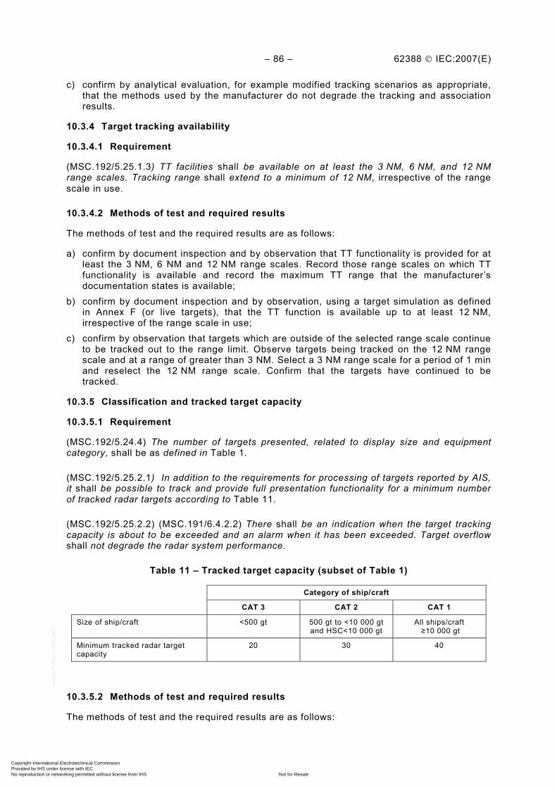
– 86 – 62388 © IEC:2007(E)
c) confirm by analytical evaluation, for example modified tracking scenarios as appropriate, that the methods used by the manufacturer do not degrade the tracking and association results.
10.3.4 Target tracking availability
10.3.4.1 Requirement
(MSC.192/5.25.1.3) TT facilities shall be available on at least the 3 NM, 6 NM, and 12 NM range scales. Tracking range shall extend to a minimum of 12 NM, irrespective of the range scale in use.
10.3.4.2 Methods of test and required results
The methods of test and the required results are as follows:
a) confirm by document inspection and by observation that TT functionality is provided for at least the 3 NM, 6 NM and 12 NM range scales. Record those range scales on which TT functionality is available and record the maximum TT range that the manufacturer’s documentation states is available;
b) confirm by document inspection and by observation, using a target simulation as defined in Annex F (or live targets), that the TT function is available up to at least 12 NM, irrespective of the range scale in use;
c) confirm by observation that targets which are outside of the selected range scale continue to be tracked out to the range limit. Observe targets being tracked on the 12 NM range scale and at a range of greater than 3 NM. Select a 3 NM range scale for a period of 1 min and reselect the 12 NM range scale. Confirm that the targets have continued to be tracked.
10.3.5 Classification and tracked target capacity
10.3.5.1 Requirement
(MSC.192/5.24.4) The number of targets presented, related to display size and equipment category, shall be as defined in Table 1.
(MSC.192/5.25.2.1) In addition to the requirements for processing of targets reported by AIS, it shall be possible to track and provide full presentation functionality for a minimum number of tracked radar targets according to Table 11.
(MSC.192/5.25.2.2) (MSC.191/6.4.2.2) There shall be an indication when the target tracking capacity is about to be exceeded and an alarm when it has been exceeded. Target overflow shall not degrade the radar system performance.
Table 11 – Tracked target capacity (subset of Table 1)
Category of ship/craft
CAT 3 CAT 2 CAT 1
Size of ship/craft <500 gt
500 gt to <10 000 gt and HSC<10 000 gt
All ships/craft ≥10 000 gt
Minimum tracked radar target capacity
20 30 40
10.3.5.2 Methods of test and required results
The methods of test and the required results are as follows:
Copyright International Electrotechnical Commission Provided by IHS under license with IEC
Not for ResaleNo reproduction or networking permitted without license from IHS
--`,,```,,,,````-`-`,,`,,`,`,,`---
62388 © IEC:2007(E) – 87 –
a) confirm by document inspection, that the equipment classification is declared when it is submitted for test and note the Table 11 requirements according to equipment category;
b) confirm by observation and using the target simulator, the radar system can process and track the required number of radar targets as specified in Table 11. The simulator shall provide the required number of test targets arranged (for example in groups) to permit an easy assessment of target count;
c) confirm by observation and using a simulated scenario that there is an indication at a nominal 95 % full capacity and that an alarm function is provided when the display presentation capacity is expected to be exceeded. For example with a declared capacity of 40 targets, an indication is required at 38 targets and an alarm when the 41
st target is
attempted to be acquired; d) confirm by observation that there is no obvious degradation in radar system performance
under the conditions of target overflow, either in presentation or in processing of information.
10.3.6 Manual acquisition
10.3.6.1 Requirement
(MSC.192/5.25.3.1) Manual acquisition of radar targets shall be provided with provision for acquiring at least the number of targets specified in Table 1. The specified minimum number of targets to be tracked may be acquired manually, automatically, or a combination of these.
10.3.6.2 Methods of test and required results
The methods of test and the required results are as follows:
a) confirm by observation, the operation and capacity of the manual acquisition function using a test scenario or live targets. The target capacity available using manual acquisition shall be at least that required according to the equipment classification in Table 11;
b) confirm by observation, that a combination of manual acquisition and automatic acquisition (where provided) permits at least the target capacity required according to the equipment classification.
10.3.7 Automatic acquisition
10.3.7.1 Requirement
(MSC.192/5.23.3.2) Automatic acquisition shall be provided where specified in Table 1. In this case, there shall be means for the user to define the boundaries of the auto-acquisition area. The boundaries of the auto-acquisition zone and any exclusion zones shall be clearly identified.
10.3.7.2 Methods of test and required results
The methods of test and the required results are as follows:
a) confirm by observation and using the target scenario simulator, that where applicable in Table 1 (i.e. CAT 1), the automatic acquisition function is available and that the target capacity is compliant to Table 11 above;
b) confirm by observation that any target entering, or detected within, the automatic acquisition area is automatically acquired. A new target symbol compliant with Annex J and an alarm shall be provided;
c) confirm by observation that the auto-acquisition zone and any exclusion zone are clearly identified on the display according to Annex J.
Copyright International Electrotechnical Commission Provided by IHS under license with IEC
Not for ResaleNo reproduction or networking permitted without license from IHS
--`,,```,,,,````-`-`,,`,,`,`,,`---
– 88 – 62388 © IEC:2007(E)
10.3.8 Motion trend
10.3.8.1 Requirement
(MSC.192/5.25.4.1) When a target is acquired, the system shall be capable of providing the trend of the target's motion within one minute and the prediction of the targets’ motion within 3 minutes.
10.3.8.2 Methods of test and required results
The methods of test and the required results are as follows:
a) confirm by observation that once targets are acquired, the system provides the trend of the target’s motion within 1 min and a prediction of a target’s motion targets within 3 min. The target motion trend and accuracy is measured in 10.3.14;
b) confirm by observation that targets continue to be tracked and that target information is updated automatically.
10.3.9 Visibility of 50 %
10.3.9.1 Requirement
(MSC.192/5.25.4.3) The system shall continue to track radar targets that are clearly and individually distinguishable on the display for 5 out of 10 consecutive scans or equivalent.
10.3.9.2 Methods of test and required results
Confirm by observation that the relevant test scenario demonstrates that the radar target is continually tracked when it is a clear and individual radar target available for 5 out of 10 scans, or its equivalent, as verified by target 6 in scenario 5 (see 10.3.13).
10.3.10 Tracking algorithm
10.3.10.1 Requirement
(MSC.192/5.25.4.4) The TT design shall be such that target vector and data smoothing is effective, while target manoeuvres shall be detected as early as possible.
When a tracked target or own ship has completed a manoeuvre, the system shall present in a period of not more than 1 min an indication of the target's motion trend, and display within 3 minutes the target's predicted motion.
10.3.10.2 Methods of test and required results
The methods of test and the required results are as follows:
a) confirm by observation that when the tracking test scenarios 2 and 3 are exercised, target vector stability is maintained and data is smoothed according to the limits specified in 10.3.13;
b) confirm by observation that the trend and prediction comply with the accuracies required in each test scenario, as defined in 10.3.13.
10.3.11 Target swap
10.3.11.1 Requirement
(MSC.192/5.25.4.5) The possibility of tracking errors, including target swap, shall be minimised by design.
Copyright International Electrotechnical Commission Provided by IHS under license with IEC
Not for ResaleNo reproduction or networking permitted without license from IHS
--`,,```,,,,````-`-`,,`,,`,`,,`---
62388 © IEC:2007(E) – 89 –
10.3.11.2 Methods of test and required results
Confirm by observation that target swap does not occur when tracking scenario 4 in 10.3.13 is exercised.
10.3.12 Cease tracking
10.3.12.1 Requirement
(MSC.192/5.25.4.6) Separate facilities for cancelling the tracking of any one and of all target(s) shall be provided.
10.3.12.2 Methods of test and required results
Confirm by observation and using scenario 5 in 10.3.13, that the functionality for cancelling any one target and also for cancelling all tracked targets is provided.
10.3.13 Target tracking scenarios
10.3.13.1 Requirement
Five tracking scenarios are provided to test the target tracking performance:
• scenario 1 replaces the four previous scenarios in IEC 60872-1 and applies the sensor errors as defined in Annex E;
• scenarios 2 and 3 test own ship turns in both directions, without sensor errors;
• scenario 4 tests for target swap, without sensor errors;
• scenario 5 provides 10 targets, including one having a 50 % visibility. No sensor errors are applied.
10.3.14 Target motion and tracking accuracy
10.3.14.1 Requirement
(MSC.192/5.24.4.2) TT shall be capable of tracking and updating the information of all acquired targets automatically.
(MSC.192/5.25.4.7) Automatic tracking accuracy shall be achieved when the tracked target has achieved a steady state, assuming the sensor errors allowed by the relevant performance standards of the IMO.
(MSC.192/5.25.4.7.1) The testing standard shall have detailed target simulation tests as a means to confirm the tracking accuracy of targets with relative speeds of up to 100 kn. Individual accuracy values shown in Table 12 may be adapted to account for the relative aspects of target motion with respect to that of own ship in the testing scenarios used.
(MSC.192/5.25.4.7.1) For ships capable of up to 30 kn true speed, the tracking facility shall present, within 1 min steady state tracking, the relative motion trend and after 3 minutes, the predicted motion of a target, within the following accuracy values (95 % probability).
(MSC.192/5.25.4.7.1) Accuracy may be significantly reduced during or shortly after acquisition, own ships manoeuvre, a manoeuvre of the target, or any tracking disturbance and is also dependent on own ship’s motion and sensor accuracy. Table 12 provides an indication of typical tracking accuracy, averaged over several tracking scenarios and with minimal sensor errors. Sensor errors with long periods are not relevant for the tracking scenarios.
Copyright International Electrotechnical Commission Provided by IHS under license with IEC
Not for ResaleNo reproduction or networking permitted without license from IHS
--`,,```,,,,````-`-`,,`,,`,`,,`---
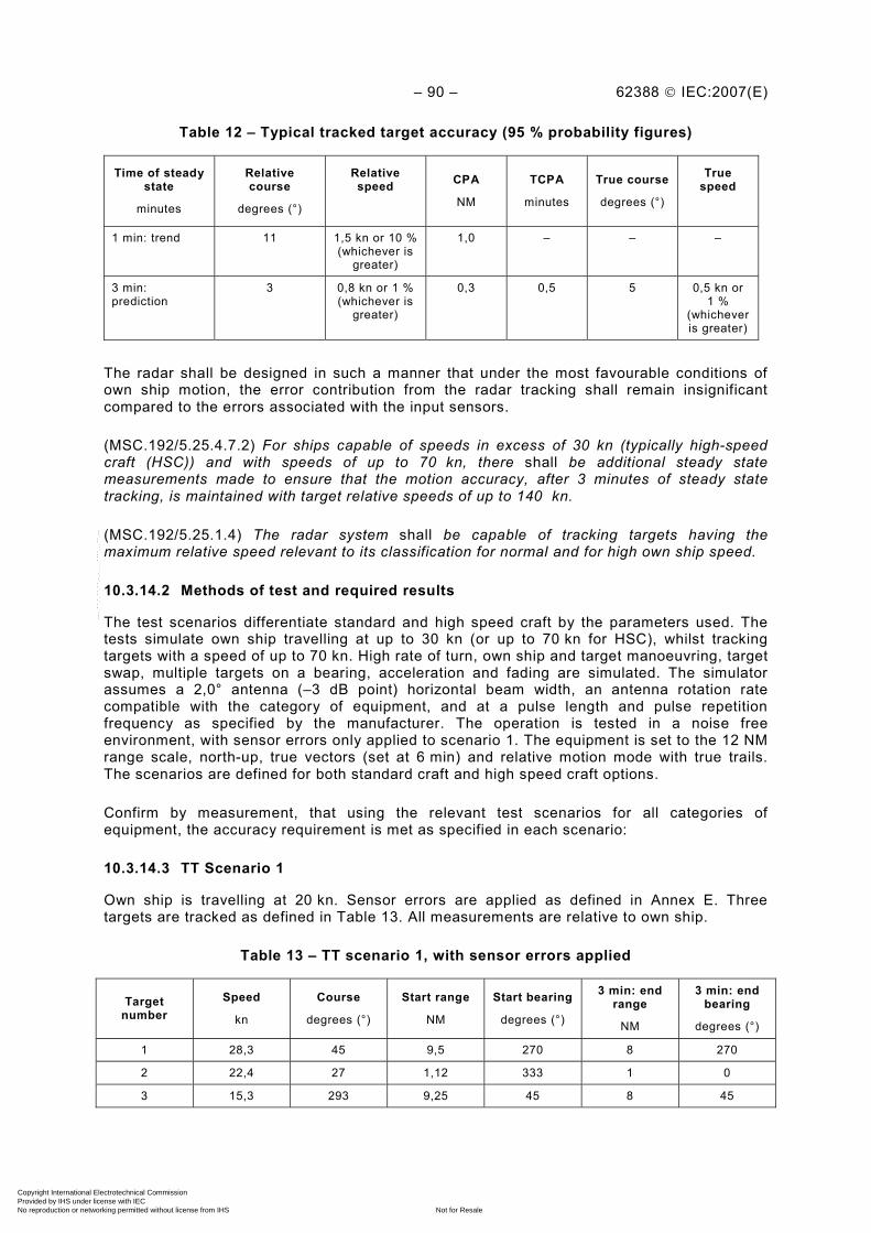
– 90 – 62388 © IEC:2007(E)
Table 12 – Typical tracked target accuracy (95 % probability figures)
Time of steady state
minutes
Relative course
degrees (°)
Relative speed
CPA
NM
TCPA
minutes
True course
degrees (°)
True speed
1 min: trend 11 1,5 kn or 10 % (whichever is
greater)
1,0 – – –
3 min: prediction
3 0,8 kn or 1 % (whichever is
greater)
0,3 0,5 5
0,5 kn or 1 %
(whichever is greater)
The radar shall be designed in such a manner that under the most favourable conditions of own ship motion, the error contribution from the radar tracking shall remain insignificant compared to the errors associated with the input sensors.
(MSC.192/5.25.4.7.2) For ships capable of speeds in excess of 30 kn (typically high-speed craft (HSC)) and with speeds of up to 70 kn, there shall be additional steady state measurements made to ensure that the motion accuracy, after 3 minutes of steady state tracking, is maintained with target relative speeds of up to 140 kn.
(MSC.192/5.25.1.4) The radar system shall be capable of tracking targets having the maximum relative speed relevant to its classification for normal and for high own ship speed.
10.3.14.2 Methods of test and required results
The test scenarios differentiate standard and high speed craft by the parameters used. The tests simulate own ship travelling at up to 30 kn (or up to 70 kn for HSC), whilst tracking targets with a speed of up to 70 kn. High rate of turn, own ship and target manoeuvring, target swap, multiple targets on a bearing, acceleration and fading are simulated. The simulator assumes a 2,0° antenna (–3 dB point) horizontal beam width, an antenna rotation rate compatible with the category of equipment, and at a pulse length and pulse repetition frequency as specified by the manufacturer. The operation is tested in a noise free environment, with sensor errors only applied to scenario 1. The equipment is set to the 12 NM range scale, north-up, true vectors (set at 6 min) and relative motion mode with true trails. The scenarios are defined for both standard craft and high speed craft options.
Confirm by measurement, that using the relevant test scenarios for all categories of equipment, the accuracy requirement is met as specified in each scenario:
10.3.14.3 TT Scenario 1
Own ship is travelling at 20 kn. Sensor errors are applied as defined in Annex E. Three targets are tracked as defined in Table 13. All measurements are relative to own ship.
Table 13 – TT scenario 1, with sensor errors applied
Target number
Speed
kn
Course
degrees (°)
Start range
NM
Start bearing
degrees (°)
3 min: end range
NM
3 min: end bearing
degrees (°)
1 28,3 45 9,5 270 8 270
2 22,4 27 1,12 333 1 0
3 15,3 293 9,25 45 8 45
Copyright International Electrotechnical Commission Provided by IHS under license with IEC
Not for ResaleNo reproduction or networking permitted without license from IHS
--`,,```,,,,````-`-`,,`,,`,`,,`---
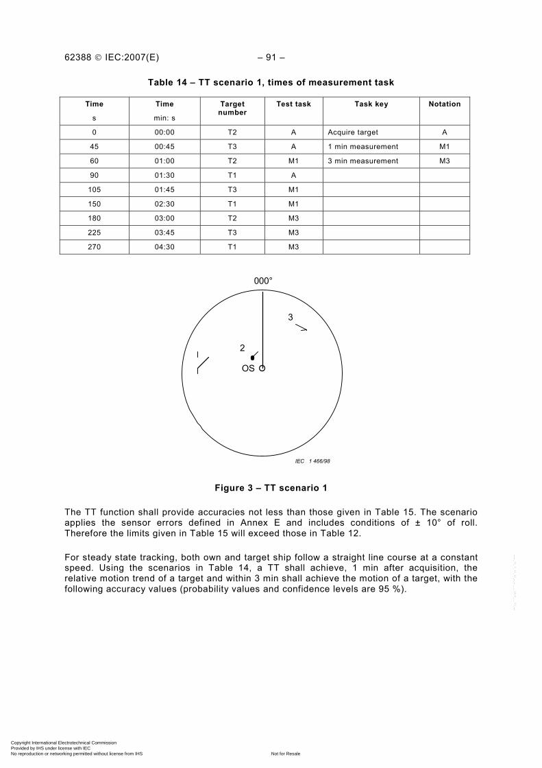
62388 © IEC:2007(E) – 91 –
Table 14 – TT scenario 1, times of measurement task
Time
s
Time
min: s
Target number
Test task Task key Notation
0 00:00 T2 A Acquire target A
45 00:45 T3 A 1 min measurement M1
60 01:00 T2 M1 3 min measurement M3
90 01:30 T1 A
105 01:45 T3 M1
150 02:30 T1 M1
180 03:00 T2 M3
225 03:45 T3 M3
270 04:30 T1 M3
OS
3
IEC 1 466/98
2
000°
Figure 3 – TT scenario 1
The TT function shall provide accuracies not less than those given in Table 15. The scenario applies the sensor errors defined in Annex E and includes conditions of ± 10° of roll. Therefore the limits given in Table 15 will exceed those in Table 12.
For steady state tracking, both own and target ship follow a straight line course at a constant speed. Using the scenarios in Table 14, a TT shall achieve, 1 min after acquisition, the relative motion trend of a target and within 3 min shall achieve the motion of a target, with the following accuracy values (probability values and confidence levels are 95 %).
Copyright International Electrotechnical Commission Provided by IHS under license with IEC
Not for ResaleNo reproduction or networking permitted without license from IHS
--`,,```,,,,````-`-`,,`,,`,`,,`---
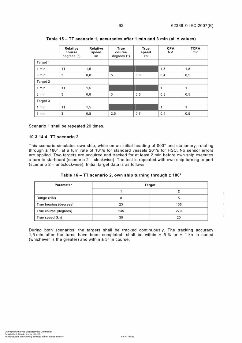
– 92 – 62388 © IEC:2007(E)
Table 15 – TT scenario 1, accuracies after 1 min and 3 min (all ± values)
Relative course
degrees (°)
Relative speed
kn
True course
degrees (°)
True speed
kn
CPA NM
TCPA min
Target 1
1 min 11 1,5 1,5 1,8
3 min 3 0,8 5 0,8 0,4 0,5
Target 2
1 min 11 1,5 1 1
3 min 3 0,8 3 0,5 0,3 0,5
Target 3
1 min 11 1,5 1 1
3 min 3 0,8 2,5 0,7 0,4 0,5
Scenario 1 shall be repeated 20 times.
10.3.14.4 TT scenario 2
This scenario simulates own ship, while on an initial heading of 000° and stationary, rotating through ± 180°, at a turn rate of 10°/s for standard vessels 20°/s for HSC. No sensor errors are applied. Two targets are acquired and tracked for at least 2 min before own ship executes a turn to starboard (scenario 2 – clockwise). The test is repeated with own ship turning to port (scenario 2 – anticlockwise). Initial target data is as follows:
Table 16 – TT scenario 2, own ship turning through ± 180°
Target Parameter
1 2
Range (NM) 8 5
True bearing (degrees) 23 135
True course (degrees) 135 270
True speed (kn) 30 20
During both scenarios, the targets shall be tracked continuously. The tracking accuracy 1,5 min after the turns have been completed, shall be within ± 5 % or ± 1 kn in speed (whichever is the greater) and within ± 3° in course.
Copyright International Electrotechnical Commission Provided by IHS under license with IEC
Not for ResaleNo reproduction or networking permitted without license from IHS
--`,,```,,,,````-`-`,,`,,`,`,,`---
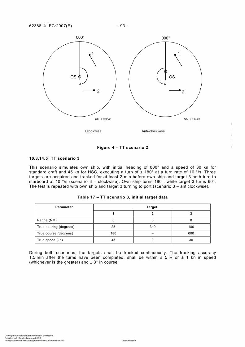
62388 © IEC:2007(E) – 93 –
OS
1
IEC 1 467/98 IEC 1 466/98
2
OS
2
1
000°000°
Clockwise Anti-clockwise
Figure 4 – TT scenario 2
10.3.14.5 TT scenario 3
This scenario simulates own ship, with initial heading of 000° and a speed of 30 kn for standard craft and 45 kn for HSC, executing a turn of ± 180° at a turn rate of 10 °/s. Three targets are acquired and tracked for at least 2 min before own ship and target 3 both turn to starboard at 10 °/s (scenario 3 – clockwise). Own ship turns 180°, while target 3 turns 60°. The test is repeated with own ship and target 3 turning to port (scenario 3 – anticlockwise).
Table 17 – TT scenario 3, initial target data
Target Parameter
1 2 3
Range (NM) 5 3 8
True bearing (degrees) 23 340 180
True course (degrees) 180 – 000
True speed (kn) 45 0 30
During both scenarios, the targets shall be tracked continuously. The tracking accuracy 1,5 min after the turns have been completed, shall be within ± 5 % or ± 1 kn in speed (whichever is the greater) and ± 3° in course.
Copyright International Electrotechnical Commission Provided by IHS under license with IEC
Not for ResaleNo reproduction or networking permitted without license from IHS
--`,,```,,,,````-`-`,,`,,`,`,,`---

– 94 – 62388 © IEC:2007(E)
OS
12
IEC 1 469/98IEC 1 468/98
3
OS
12
3
000° 000°
Clockwise Anti-clockwise
Figure 5 – TT scenario 3
10.3.14.6 TT scenario 4
This scenario simulates a fast target approaching and passing own ship. Own ship travels on a heading of 45° at a speed of 28 kn for standard vessels and 70 kn for HSC, on a straight course. A target travels at 70 kn on a reciprocal course.
Own ship and the target’s tracks are separated by a buoy. The buoy has a 0,5 NM CPA to both own ship and the target. The high speed target and the buoy are acquired immediately after the scenario has begun (see Figure 6).
Table 18 – TT scenario 4, initial target data for fast targets (standard speed ships)
Target Parameter
1 2
Range (NM) 2,02 7,01
True bearing (degrees) 031 037
True course (degrees) 0 225
True speed (kn) 0 70
Table 19 – TT scenario 4, initial target data for fast targets (HSC)
Target Parameter
1 2
Range (NM) 5 10
True bearing (degrees) 040 040
True course (degrees) 0 225
True speed (kn) 0 70
The high-speed target and the buoy shall be tracked continuously and without target swap. The target data shall be checked 2 min after acquisition and again 5 min and 7 min after
Copyright International Electrotechnical Commission Provided by IHS under license with IEC
Not for ResaleNo reproduction or networking permitted without license from IHS
--`,,```,,,,````-`-`,,`,,`,`,,`---

62388 © IEC:2007(E) – 95 –
acquisition. The tracking accuracy shall be within ± 5 % or ± 1 kn in speed (whichever is the greater) and within ± 3° in course.
OS
1
2
000°
IEC 2249/07
Figure 6 – TT scenario 4
10.3.14.7 TT Scenario 5
This scenario simulates a typical collision situation, with ten ships being tracked and one with zero CPA. During the scenario, four targets are tracked on a single bearing, tangential targets are tracked, own ship changes speed and performance is tested with a fading target. Own ship is off-centred 50 % towards a bearing of 135°. The heading is 315° true.
a) For standard ship speeds, own ship speed is initially 25 kn. This speed shall be maintained for 7 min. After 7 min own ship speed shall decrease linearly to 15 kn The deceleration shall be at a rate of 0,5 kn/s. The speed of 15 kn shall be maintained for the remainder of the test.
Table 20 – TT scenario 5: initial target data for standard craft
Target Parameter
1 2 3 4 5 6 7 8 9 10
Range (NM) 4,47 5,10 6,71 7,07 12,0 11,0 14,4 8,0 9,0 10,0
True bearing (degrees) 288 304 288 307 352 315 349 318 318 318
True course (degrees) 045 045 045 – 200 225 190 – – –
True speed (kn) 20 30 40 0 60 20 40 – – –
NOTE Target 6 – fades and has only 50 % paint
Target 7 has a zero CPA before the speed change. Targets 4, 8, 9 and 10 are stationary, with targets 8, 9, and 10 on a similar bearing. Crossing targets then provide the fourth target on a bearing. The scenario shall run for 15 min from the start. All targets shall be acquired within the first minute at time to, the time when a target is initially tracked. No sensor errors shall be applied.
b) For HSC, own ship speed is initially 60 kn. This speed shall be maintained for 7 min. After 7 min own ship speed shall decrease linearly to 40 kn. The deceleration shall be at a rate of 1 kn/s. The speed of 40 kn shall be maintained for the remainder of the test.
Copyright International Electrotechnical Commission Provided by IHS under license with IEC
Not for ResaleNo reproduction or networking permitted without license from IHS
--`,,```,,,,````-`-`,,`,,`,`,,`---
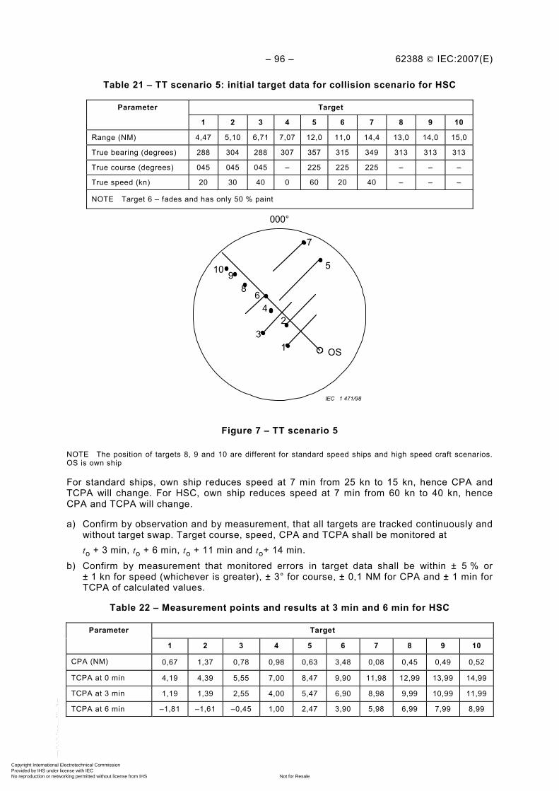
– 96 – 62388 © IEC:2007(E)
Table 21 – TT scenario 5: initial target data for collision scenario for HSC
Target Parameter
1 2 3 4 5 6 7 8 9 10
Range (NM) 4,47 5,10 6,71 7,07 12,0 11,0 14,4 13,0 14,0 15,0
True bearing (degrees) 288 304 288 307 357 315 349 313 313 313
True course (degrees) 045 045 045 – 225 225 225 – – –
True speed (kn) 20 30 40 0 60 20 40 – – –
NOTE Target 6 – fades and has only 50 % paint
IEC 1 471/98
OS
10 98
6 4
32
1
5
7
000°
Figure 7 – TT scenario 5
NOTE The position of targets 8, 9 and 10 are different for standard speed ships and high speed craft scenarios. OS is own ship
For standard ships, own ship reduces speed at 7 min from 25 kn to 15 kn, hence CPA and TCPA will change. For HSC, own ship reduces speed at 7 min from 60 kn to 40 kn, hence CPA and TCPA will change.
a) Confirm by observation and by measurement, that all targets are tracked continuously and without target swap. Target course, speed, CPA and TCPA shall be monitored at
to + 3 min, to + 6 min, to + 11 min and to+ 14 min.
b) Confirm by measurement that monitored errors in target data shall be within ± 5 % or ± 1 kn for speed (whichever is greater), ± 3° for course, ± 0,1 NM for CPA and ± 1 min for TCPA of calculated values.
Table 22 – Measurement points and results at 3 min and 6 min for HSC
Target Parameter
1 2 3 4 5 6 7 8 9 10
CPA (NM) 0,67 1,37 0,78 0,98 0,63 3,48 0,08 0,45 0,49 0,52
TCPA at 0 min 4,19 4,39 5,55 7,00 8,47 9,90 11,98 12,99 13,99 14,99
TCPA at 3 min 1,19 1,39 2,55 4,00 5,47 6,90 8,98 9,99 10,99 11,99
TCPA at 6 min –1,81 –1,61 –0,45 1,00 2,47 3,90 5,98 6,99 7,99 8,99
Copyright International Electrotechnical Commission Provided by IHS under license with IEC
Not for ResaleNo reproduction or networking permitted without license from IHS
--`,,```,,,,````-`-`,,`,,`,`,,`---
62388 © IEC:2007(E) – 97 –
Table 23 – Measurement points and results at 11 min and 14 min for HSC
Target Parameter
1 2 3 4 5 6 7 8 9 10
CPA (NM) 1,10 0,79 0,38 0,98 0,98 3,85 1,06 0,45 0,49 0,52
TCPA at 7 min 20 s –4,20 –4,12 –2,36 –0,41 1,24 3,00 5,87 8,57 10,07 11,57
TCPA at 11 min –7,87 –7,79 –6,02 –4,08 –2,43 –0,67 2,20 4,90 6,40 7,90
TCPA at 14 min –10,87 –10,79 –9,02 –7,08 –5,43 –3,67 –0,80 1,90 3,40 4,90
Table 24 – Measurement points and results at 3 min and 6 min for standard craft
Target Parameter
1 2 3 4 5 6 7 8 9 10
CPA (NM) 0,90 3,22 3,46 0,98 2,12 6,87 0,09 0,42 0,47 0,52
TCPA at 0 min 8,20 6,07 7,32 16,80 9,56 16,10 14,88 19,17 21,57 23,97
TCPA at 3 min 5,20 3,07 4,32 13,80 6,56 13,10 11,88 16,17 18,57 20,97
TCPA at 6 min 2,20 0,07 1,32 10,80 3,56 10,10 8,88 13,17 15,57 17,97
Table 25 – Measurement points and results at 11 min and 14 min for standard craft
Target Parameter
1 2 3 4 5 6 7 8 9 10
CPA (NM) 1,03 3,00 3,43 0,98 2,45 7,87 0,94 0,42 0,47 0,52
TCPA at 7min 20 s 0,62 –2,70 –0,95 16,00 2,25 6,83 8,73 19,95 23,95 27,94
TCPA at 11 min –3,06 –6,39 –4,64 12,32 –1,43 3,14 5,04 16,27 20,26 24,26
TCPA at 14 min –6,07 –9,39 –7,64 9,31 –4,44 0,14 2,04 13,26 17,26 21,25
10.3.14.8 Tracking in an over-sea environment
In addition to tracking system tests using simulated targets generated by a target simulator in a noise-free environment, the tracking system shall demonstrate tracking capability in a noisy environment and additionally in a clutter environment.
10.3.14.9 Methods of test and required results
The methods of test and the required results are as follows:
a) confirm by observation that when the test targets in scenario 5 are set to 10 dB above peak noise level, they are tracked without degradation of the tracking performance;
b) confirm by observation that when the tracking system is operated in a typical clutter environment and using targets of opportunity (targets of different sizes, speeds and trajectories), continue to be tracked with minimal degradation to tracking performance.
10.3.15 Tracker range and bearing accuracy
(MSC.192/5.25.4.7.1) The measured target range shall be within 50 m or ± 1 % of target range, whichever is greater, and the bearing shall be within 2° with the own ship sensor errors listed in Annex E (without glint, pitch and roll).
Copyright International Electrotechnical Commission Provided by IHS under license with IEC
Not for ResaleNo reproduction or networking permitted without license from IHS
--`,,```,,,,````-`-`,,`,,`,`,,`---
– 98 – 62388 © IEC:2007(E)
10.3.15.1 Methods of test and required results
Confirm by measurement that two simulated targets as defined in Table 26 meet the accuracy requirements of within 50 m or ± 1 % of target range, whichever is greater, and within 2° in bearing. The scenario uses two targets which are motionless relative to own ship, and own ship has a speed of 15 kn. Target 1 has a side aspect and target 2 has an end-on aspect.
Table 26 – Measurement of tracked target accuracy
Target Parameter
1 2
Range (NM) 3,0 3,0
True bearing (degrees) 270 000
True course (degrees) 000 000
True speed (kn) 15 15
Aspect Side End on
NOTE The target range and bearing accuracy is very dependent on the magnitude of sensor errors and the stability of a tracked target. Accuracy is optimum in a steady state tracking condition and using a stable radar platform. Range and bearing accuracy improve with minimal sensor errors and where there are no sensor errors shall be comparable with navigation tools, once steady state tracking has been achieved.
10.3.16 Reference target
10.3.16.1 Requirement
(MSC.192/5.25.4.8) A ground referencing function, based on a stationary tracked target, shall be provided. Targets used for this function shall be marked with the relevant symbol defined in Annex J.
10.3.16.2 Methods of test and required results
The methods of test and the required results are as follows:
a) confirm by document inspection and by observation, that the ground referencing function, based on one or more stationary tracked targets, is available;
b) confirm by observation that the reference target function is either inhibited when AIS is switched on, or the use of the reference target is limited for the calculation of true speed and course but not for the calculation of relative values of speed, course and CPA/TCPA;
c) confirm by observation that stationary tracked reference targets are labelled with the specified reference target symbol in Annex J;
d) confirm by document inspection that the user manual provides a warning that the loss of a reference target may have a major impact on the accuracy of the results for true speed and true course of the target and that own speed will be degraded;
e) confirm by observation that an alarm is provided when tracking accuracy is degraded by the loss of the reference target(s). The manufacturer shall declare and explain the techniques used to detect the loss of a reference target;
f) confirm by document inspection that the user manual describes the functionality, limitations and possible loss of accuracy, when the reference target is lost;
g) confirm that the user manual advises that reference targets are only used for the calculation of true speed and how calculation of the relative speed can be dangerous.
Copyright International Electrotechnical Commission Provided by IHS under license with IEC
Not for ResaleNo reproduction or networking permitted without license from IHS
--`,,```,,,,````-`-`,,`,,`,`,,`---

62388 © IEC:2007(E) – 99 –
10.4 Tracking limitations
10.4.1 Tracking warnings
10.4.1.1 Requirement
(MSC.192/5.25.4.7.1) The testing standard shall have detailed target simulation tests as a means to confirm the accuracy of targets with relative speeds of up to 100 kn. The test programme(s) shall be available so that the overall performance of tracking can be assessed periodically against a known solution. The system shall provide suitable warnings of a tracking malfunction to enable the observer to monitor the correct operation of the system.
10.4.1.2 Methods of test and required results
The methods of test and the required results are as follows:
a) confirm by observation that a test(s) simulation is provided to a known solution and that the simulation, together with the solution, is described in the user manual;
b) confirm by observation that the relevant symbol is indicated for a simulation function according to Annex J and that the malfunction warnings are correctly indicated;
c) confirm by document inspection that the user manual describes warnings of a tracking malfunction;
d) the simulation facility may also provide a familiarisation function as described in 17.1.
10.4.2 Documentation
10.4.2.1 Requirement
(MSC.192/6.3.2) The equipment documentation shall include a description of the limitations of the tracking process.
10.4.2.2 Methods of test and required results
Confirm by document inspection that the limitations of the tracking process are described in the users’ manual.
10.5 Automatic identification system
10.5.1 General
AIS can assist in safe navigation and can provide additional information to support the task of collision avoidance. Class A AIS is provided for SOLAS ships and provides full data. Class B AIS is for non-SOLAS craft providing a subset of that data. Different messages for Class A and Class B allow the target category to be identified. The AIS data reporting rate varies according to the status and motion of the ship.
Where reported AIS targets are provided on a navigational display and the purpose of that display is for collision avoidance, radar video shall be provided and tracked target data from a radar system shall be used. In this case, the reported AIS information shall be time-stamped and the position of the AIS symbology shall be progressively moved according to lapsed time so as to be collocated with the radar video in accordance with 10.8. The navigational display shall not track targets or provide target association functionality unless it is fully compliant with this standard.
NOTE The AIS target state diagram is shown in Annex G.
– 100 – 62388 © IEC:2007(E)
10.5.2 AIS target capacity
10.5.2.1 Requirement
(MSC.192/5.26.2) In addition to the requirements for radar tracking, it shall be possible to display and provide full presentation functionality for a minimum number of sleeping and activated AIS targets according to Table 27.
The AIS target display capacity defines the maximum number of AIS targets which can be displayed.
(MSC.192/5.26.2) (MSC.191/6.4.2.2) There shall be an indication when the capacity of processing /display of AIS targets is about to be exceeded, and an alarm when the capacity has been exceeded.
The minimum display capacity for activated and sleeping targets shall conform to Table 27 and these quantities shall be referred to as the activated and sleeping target processing capacities. The equipment shall be capable of filtering the sleeping AIS targets exceeding the requirements in Table 27.
The documentation shall describe the display and processing capacity for the equipment and in addition, shall describe the operation in the event that capacity is at or close to, the maximum capacity provided.
Table 27 – AIS target display capacity (subset of Table 1)
Category of ship/craft
CAT 3 CAT 2 CAT 1
Size of ship/craft <500 gt 500 gt to <10 000 gt, and HSC<10 000 gt
All ships/craft ≥10 000 gt
Minimum activated AIS target display/processing capacity
20 30 40
Minimum sleeping AIS target display/processing capacity
100 150 200
Minimum target filtering capacity Fully populated VDM Fully populated VDM Fully populated VDM
10.5.2.2 Methods of test and required results
The methods of test and the required results are as follows:
a) confirm by document inspection, and record, the manufacturer’s stated AIS target display processing and filtering capacity of the equipment. The documentation shall confirm that the minimum display capacity for activated and sleeping targets conforms to Table 27, and that the equipment is capable of filtering the sleeping AIS targets exceeding the requirements in Table 27;
b) confirm by observation and using the reported target simulator (RTS) as described in Annex F, that the display capacity for activated and sleeping targets is achieved according to the equipment category, and that the appropriate indication and alarm functions are provided, unless there is a target-limiting parameter as described in c);
c) confirm by observation that there is an alphanumeric and/or a graphic indication of the target-limiting parameter which is provided to automatically limit the display of AIS targets, for example by range, CPA or TCPA. The RTS simulator shall be used to provide in excess of the sleeping target capacity and the closest targets within the stated capacity and within the filter limits shall be displayed;
Copyright International Electrotechnical Commission Provided by IHS under license with IEC
Not for ResaleNo reproduction or networking permitted without license from IHS
--`,,```,,,,````-`-`,,`,,`,`,,`---
62388 © IEC:2007(E) – 101 –
d) confirm by observation that if the display capacity of the EUT (activated targets) is at 95 % of the stated manufacturer’s target display processing capacity or at a level set by the user, an indication is given;
e) confirm by observation that when 10 additional AIS targets are provided close to own ship, the additional targets are displayed;
f) confirm by document inspection, that the user manual describes how the EUT behaves in a target-overload situation: – when the activated target count has been exceeded; – when the sleeping target count has been exceeded.
10.5.3 Filtering of AIS sleeping targets
10.5.3.1 Requirement
(MSC.192/5.26.3) To reduce display clutter, a means to filter the presentation of sleeping AIS targets shall be provided, together with an indication of the filter status (for example by target range, CPA/TCPA or AIS target class A/B, etc.). It shall not be possible to remove individual AIS targets from the display.
(MSC.192/5.26.1) Reported targets provided by the AIS may be filtered according to user-defined parameters. Targets may be sleeping, or may be activated. Activated targets are treated in a similar way to radar tracked targets.
(MSC.191/6.4.3.2) The filter criteria in use shall be readily available.
10.5.3.2 Methods of test and required results
The methods of test and the required results are as follows:
a) confirm by document inspection that the user manual describes the basic functionality of the filters available;
b) confirm by observation and using the RTS simulator, the filter provides and conforms to the functions described in the user manual;
c) confirm by observation that it is not possible for the user to select a target manually to remove individual AIS targets from the display;
d) confirm by observation that the filter criteria in use are readily available.
10.5.4 Activation and deactivation of AIS targets
10.5.4.1 Requirement
(MSC.192/5.26.4) A means to activate a sleeping AIS target and to deactivate an activated AIS target shall be provided. If zones for the automatic activation of AIS targets are provided, they shall be the same as for automatic radar target acquisition. In addition, sleeping AIS targets may be automatically activated when meeting user defined parameters (for example target range, CPA/TCPA or AIS target Class A/B). The manufacturer shall state what user defined parameters are available and shall show that they are described in the user manual.
10.5.4.2 Methods of test and required results
The methods of test and the required results are as follows:
a) confirm by observation that a function is provided to activate a sleeping target and to deactivate an activated target;
b) confirm by observation that where automatic activation zones are provided, they have the same properties as those provided for automatic radar target acquisition;
c) confirm by observation that a function is provided to automatically activate sleeping AIS targets when those targets meet user defined parameters for activation;
Copyright International Electrotechnical Commission Provided by IHS under license with IEC
Not for ResaleNo reproduction or networking permitted without license from IHS
--`,,```,,,,````-`-`,,`,,`,`,,`---
– 102 – 62388 © IEC:2007(E)
d) confirm by document inspection that the user defined parameters and the associated functionality are described in the user manual.
10.5.5 AIS functionality and presentation
10.5.5.1 Requirement
The AIS functionality is similar to that of tracked targets. The AIS functions shall apply as required in this standard, meeting the requirements of this clause. The presentation requirements of reported AIS targets shall be in accordance with Clause 6, Annex J and this subclause.
NOTE Table 4 in MSC.192/5.26.5, AIS presentation status, is not duplicated here as the functionality is included within clauses in this standard.
(MSC.191/6.4.5.5) The orientation of the AIS target symbol shall indicate its heading. If the heading information is not received, the orientation of the AIS symbol shall be aligned to the COG. When available, the turn or rate of turn (ROT) indicator and/or the path prediction shall indicate the manoeuvre of an activated AIS target.
(MSC.192/5.27) Targets shall be presented with their relevant symbols according to the performance standards for the Presentation of Navigation-related Information on Shipborne Displays, adopted by the IMO MSC.191(79) and SN/Circ.243.
(MSC.191/6.4.5.2) AIS information shall be graphically presented as sleeping or activated targets.
(MSC.192/5.27.1) AIS targets that are displayed shall be presented as sleeping targets by default.
(MSC.192/5.27.2) The course and speed of a tracked radar target or reported AIS target shall be indicated by a predicted motion vector. The vector time shall be adjustable and valid for presentation of any target regardless of its source.
(MSC.192/5.27.3) A permanent indication of vector mode, time and stabilisation shall be provided. The AIS vector properties shall be generally consistent with those of TT vectors.
(MSC.192/5.27.4) The consistent common reference point shall be used for the alignment of tracked radar and AIS symbols with other information on the same display.
(MSC.192/5.27.5) On large scale / low range displays, a means to present the true scale outline of an activated AIS target shall be provided.
(MSC.192/5.27.5) It shall be possible to display the past track of activated targets.
To provide co-location for radar video and for AIS symbology, the reported AIS information shall be time-referenced so that AIS symbology shall be progressively positioned according to its velocity.
The co-location for radar video and for AIS symbology shall be provided independently from the selected speed reference.
Radar shall be able to handle and display in an appropriate way, as noted in the related IMO performance standards, the following VDL messages:
a) Messages: 1, 2, 3 and 5 (Class A AIS); b) Messages: 18, 19 and 24 (Class B AIS); c) Message 4 (AIS Base stations);
Copyright International Electrotechnical Commission Provided by IHS under license with IEC
Not for ResaleNo reproduction or networking permitted without license from IHS
--`,,```,,,,````-`-`,,`,,`,`,,`---
62388 © IEC:2007(E) – 103 –
d) Message 9 (AIS on Airborne SAR-craft); e) Message 21 (AIS for ATON); f) Messages 12 and 14 (Safety related messages).
10.5.5.2 Methods of test and required results
The methods of test and the required results are as follows:
a) confirm by observation that the symbology presented is compliant with Annex J; b) confirm by observation and using the AIS target simulator that the AIS processing function
provides a sleeping target status by default, and that a symbol compliant with Annex J is provided;
c) confirm by observation that a permanent indication of vector mode and stabilisation is provided, and as a minimum, vector time is readily available in a top level menu;
d) confirm by observation and using the target simulator, that TT and AIS targets’ course and speed are represented by a vector which represents predicted motion and that the vector velocity is modified correctly according to the stabilisation selected. Confirm that with ground stabilisation selected, ground fixed targets shall not have trails displayed;
e) confirm by observation, that a function is provided for the adjustment for the vector time (length) and that the vector time applies to any target, regardless of source;
f) confirm by observation that the vector presentation properties are according to Annex J; g) confirm by observation that the CCRP is used for the alignment (relevant positioning) of
AIS symbols; h) confirm by observation, that a means to provide a true scale outline of an activated target
is available and that the presentation is according to Annex J. The outline of the target may be presented automatically, for example by range scale, or can be manually selected;
i) confirm by observation, that the equipment provides functionality to support past track positions for activated AIS targets, and that the past track plot intervals provided are compatible with the range scale selected. Confirm by inspection, that the past track symbols conform to Annex J;
j) confirm by observation and using the RTS simulator or live radar target signals that the equipment provides co-location for Radar video and for AIS symbology by time-referencing the reported AIS information so that AIS symbology is progressively positioned according to its velocity. The AIS position shall be observed to be co-located with the related radar video on each scan;
k) check by using an RTS simulator or real targets that co-location for radar video and for AIS is present when the target is moving with low speed in an environment with set and drift and a water tracking log is selected on the radar under test;
l) confirm by using an AIS simulator or real AIS targets that the system is capable of handing the following AIS messages: 1) Messages: 1, 2, 3 and 5; 2) Messages: 18, 19 and 24; 3) Message 4; 4) Message 9; 5) Message 21; 6) Messages: 12 and 14
in an appropriate way in alphanumeric and/or graphical form as requested by the related IMO performance standard.
Copyright International Electrotechnical Commission Provided by IHS under license with IEC
Not for ResaleNo reproduction or networking permitted without license from IHS
--`,,```,,,,````-`-`,,`,,`,`,,`---

– 104 – 62388 © IEC:2007(E)
10.6 Radar and AIS target data
10.6.1 General
The selection and content of target data is defined in this clause.
10.6.1.1 Requirement
(MSC.192/5.28.1) It shall be possible to select any tracked radar or AIS target for the alphanumeric display of its data. A target selected for the display of its alphanumeric information shall be identified by the relevant symbol. If more than one target is selected for data display, the relevant symbols and the corresponding data shall be clearly identified. There shall be a clear indication to show that the target data is derived from the radar or from AIS.
(MSC.192/5.28.2) For each selected tracked radar target, the following data shall be presented in alphanumeric form:
– source(s) of data, actual range of target, actual bearing of target, predicted target range at the closest point of approach (CPA), predicted time to CPA (TCPA), true course of target, true speed of target.
(MSC.192/5.28.3) For each selected AIS target the following data shall be presented in alphanumeric form:
– source(s) of data, ship’s identification, navigational status, position where available and its quality, range, bearing, COG, SOG, CPA, and TCPA. Target heading and reported rate of turn shall also be made available. Additional target information shall be provided on request. Where sea stabilisation is selected, the CTW and STW shall be presented in place of COG and SOG.
The calculation of data from AIS information shall be verified.
(MSC.192/5.28.4) If the received AIS information is incomplete, the absent information shall be clearly indicated as ‘missing’ within the target data field.
(MSC.192/5.28.5) The data shall be displayed and continually updated, until another target is selected for data display or until the window is closed.
(MSC.192/5.28.6) Means shall be provided to present own ship AIS data on request.
10.6.1.2 Methods of test and required results
The methods of test and the required results are as follows:
a) confirm by observation that the equipment provides function to select a target and that when selected, a target data field is provided for that target;
b) confirm by observation that the equipment provides the functionality to support TT information and that the data provided conforms to the requirement;
c) confirm by observation that the target parameters are presented in accordance with the above;
d) confirm by observation that the equipment provides the functionality to support AIS information and that the data provided conforms to the requirement. If the received AIS information is incomplete, confirm that the absent information is clearly indicated as “missing” within the data field;
e) confirm by analytical evaluation and by measurement that the data derived from calculations on AIS information are correct. Verify the calculations by simulating the reported message for 10 AIS targets. The data and graphical presentation resulting from the calculations shall be verified against the known simulation solution. The verification
Copyright International Electrotechnical Commission Provided by IHS under license with IEC
Not for ResaleNo reproduction or networking permitted without license from IHS
--`,,```,,,,````-`-`,,`,,`,`,,`---
62388 © IEC:2007(E) – 105 –
shall include target data, AIS target vectors and the conversion from ground stabilised to sea stabilised information. The accuracy of AIS calculations is verified in 10.8;
f) confirm by observation and by analytical evaluation that the AIS graphical and target related information responds correctly when sea stabilisation is selected. A significant set (for example broad on the bow or beam) and drift (for example 5 kn) shall be applied;
g) confirm by observation and using the target simulator, that it is possible to select TT or AIS information by a simple user action;
h) confirm by observation that a selected target data is displayed and is continually updated, until another target is selected or until the window is closed;
i) confirm by observation that if the EUT provides a function to select multiple targets simultaneously, as a minimum a subset of paired target data is provided, for example CPA/TCPA, range and bearing, course and speed, bow crossing range and bow crossing time (BCR/BCT, see 10.6.2). If more than one target is selected for data display, the relevant symbols and the corresponding data shall be clearly identified;
j) confirm by observation that functionality is available to present own ship data and that the data presentation is in accordance with Annex J.
10.6.2 Bow crossing range and time (BCR/BCT)
10.6.2.1 General
The radar system may provide a function to measure bow crossing range and time.
10.6.2.2 Methods of test and required results
Confirm by measurement that when the bow crossing function is provided, all crossing range and time measurements are referred to the ship’s bow and not to the CCRP.
10.7 Operational target alarms
10.7.1 General
These subclauses include tests for the CPA/TCPA alarm, new target alarm and lost target alarm.
10.7.2 CPA and TCPA
10.7.2.1 Requirement
(MSC.192/5.29.1) If the calculated CPA and TCPA values of a tracked target or activated AIS target are less than the set limits, a CPA/TCPA alarm shall be given and shall be identified as such and the target causing the alarm shall be clearly indicated. Provision for enabling or disabling the CPA/TCPA AIS automatic activation function shall be provided and the disable status shall be indicated. CPA and TCPA calculations shall only be provided on navigation displays in compliance with 10.5 and Annex A of this standard.
NOTE Disabling the CPA/TCPA AIS automatic activation function requires that the CPA/TCPA function and alarm is switched off.
(MSC.192/5.29.2) The preset CPA/TCPA limits applied to targets from radar and AIS shall be identical. As a default state, the CPA/TCPA alarm functionality shall be applied to all activated AIS targets. On user request, the CPA/TCPA alarm functionality may also be applied to sleeping targets.
10.7.2.2 Methods of test and required results
The methods of test and the required results are as follows:
a) confirm by observation and using the target simulator that a selection of TT and activated AIS targets which are set to approach own ship and are within the CPA and TCPA limits,
Copyright International Electrotechnical Commission Provided by IHS under license with IEC
Not for ResaleNo reproduction or networking permitted without license from IHS
--`,,```,,,,````-`-`,,`,,`,`,,`---
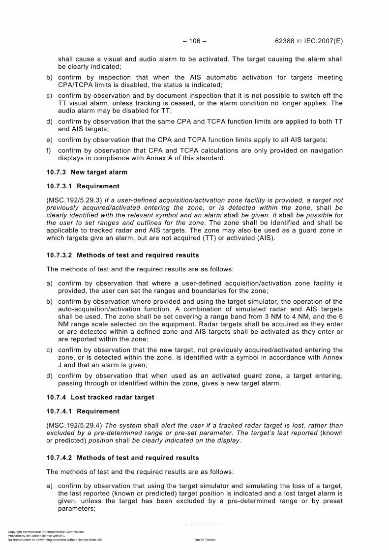
– 106 – 62388 © IEC:2007(E)
shall cause a visual and audio alarm to be activated. The target causing the alarm shall be clearly indicated;
b) confirm by inspection that when the AIS automatic activation for targets meeting CPA/TCPA limits is disabled, the status is indicated;
c) confirm by observation and by document inspection that it is not possible to switch off the TT visual alarm, unless tracking is ceased, or the alarm condition no longer applies. The audio alarm may be disabled for TT;
d) confirm by observation that the same CPA and TCPA function limits are applied to both TT and AIS targets;
e) confirm by observation that the CPA and TCPA function limits apply to all AIS targets; f) confirm by observation that CPA and TCPA calculations are only provided on navigation
displays in compliance with Annex A of this standard.
10.7.3 New target alarm
10.7.3.1 Requirement
(MSC.192/5.29.3) If a user-defined acquisition/activation zone facility is provided, a target not previously acquired/activated entering the zone, or is detected within the zone, shall be clearly identified with the relevant symbol and an alarm shall be given. It shall be possible for the user to set ranges and outlines for the zone. The zone shall be identified and shall be applicable to tracked radar and AIS targets. The zone may also be used as a guard zone in which targets give an alarm, but are not acquired (TT) or activated (AIS).
10.7.3.2 Methods of test and required results
The methods of test and the required results are as follows:
a) confirm by observation that where a user-defined acquisition/activation zone facility is provided, the user can set the ranges and boundaries for the zone;
b) confirm by observation where provided and using the target simulator, the operation of the auto-acquisition/activation function. A combination of simulated radar and AIS targets shall be used. The zone shall be set covering a range band from 3 NM to 4 NM, and the 6 NM range scale selected on the equipment. Radar targets shall be acquired as they enter or are detected within a defined zone and AIS targets shall be activated as they enter or are reported within the zone;
c) confirm by observation that the new target, not previously acquired/activated entering the zone, or is detected within the zone, is identified with a symbol in accordance with Annex J and that an alarm is given;
d) confirm by observation that when used as an activated guard zone, a target entering, passing through or identified within the zone, gives a new target alarm.
10.7.4 Lost tracked radar target
10.7.4.1 Requirement
(MSC.192/5.29.4) The system shall alert the user if a tracked radar target is lost, rather than excluded by a pre-determined range or pre-set parameter. The target’s last reported (known or predicted) position shall be clearly indicated on the display.
10.7.4.2 Methods of test and required results
The methods of test and the required results are as follows:
a) confirm by observation that using the target simulator and simulating the loss of a target, the last reported (known or predicted) target position is indicated and a lost target alarm is given, unless the target has been excluded by a pre-determined range or by preset parameters;
Copyright International Electrotechnical Commission Provided by IHS under license with IEC
Not for ResaleNo reproduction or networking permitted without license from IHS
--`,,```,,,,````-`-`,,`,,`,`,,`---
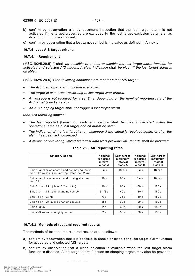
62388 © IEC:2007(E) – 107 –
b) confirm by observation and by document inspection that the lost target alarm is not activated if the target properties are excluded by the lost target exclusion parameter as described in the user manual;
c) confirm by observation that a lost target symbol is indicated as defined in Annex J.
10.7.5 Lost AIS target criteria
10.7.5.1 Requirement
(MSC.192/5.29.5) It shall be possible to enable or disable the lost target alarm function for activated and selected AIS targets. A clear indication shall be given if the lost target alarm is disabled.
(MSC.192/5.29.5) If the following conditions are met for a lost AIS target:
• The AIS lost target alarm function is enabled.
• The target is of interest, according to lost target filter criteria.
• A message is not received for a set time, depending on the nominal reporting rate of the AIS target (see Table 28)
• An AIS sleeping target shall not trigger a lost target alarm.
then, the following applies:
• The last reported (known or predicted) position shall be clearly indicated within the operational area as a lost target and an alarm be given
• The indication of the lost target shall disappear if the signal is received again, or after the alarm has been acknowledged.
• A means of recovering limited historical data from previous AIS reports shall be provided.
Table 28 – AIS reporting rates
Category of ship Nominal reporting interval class A
Lost target maximum interval class A
Nominal reporting interval class B
Lost target maximum interval class B
Ship at anchor or moored and not moving faster than 3 kn (class B not moving faster than 2 kn)
3 min 18 min 3 min 18 min
Ship at anchor or moored and moving at more than 3 kn
10 s 60 s 3 min 18 min
Ship 0 kn– 14 kn (class B 2 – 14 kn) 10 s 60 s 30 s 180 s
Ship 0 kn– 14 kn and changing course 3 1/3 s 60 s 30 s 180 s
Ship 14 kn– 23 kn 6 s 36 s 30 s 180 s
Ship 14 kn– 23 kn and changing course 2 s 36 s 30 s 180 s
Ship >23 kn 2 s 30 s 30 s 180 s
Ship >23 kn and changing course 2 s 30 s 30 s 180 s
10.7.5.2 Methods of test and required results
The methods of test and the required results are as follows:
a) confirm by observation that it is possible to enable or disable the lost target alarm function for activated and selected AIS targets;
b) confirm by observation that a clear indication is available when the lost target alarm function is disabled. A lost target alarm function for sleeping targets may also be provided;
Copyright International Electrotechnical Commission Provided by IHS under license with IEC
Not for ResaleNo reproduction or networking permitted without license from IHS
--`,,```,,,,````-`-`,,`,,`,`,,`---

– 108 – 62388 © IEC:2007(E)
c) confirm by observation, the operation of the lost target alarm functionality using the target simulator, and that the last reported (known or predicted) AIS target position is indicated with a lost target symbol according to Annex J.
10.8 Target association
10.8.1 General
This function provides the means to associate a tracked target and a reported target according to an association algorithm. Time referencing (time stamping) for reported AIS targets and for target tracking information is essential to perform this task.
10.8.2 Association and priority
10.8.2.1 Requirement
(MSC.192/5.30) An automatic target association function shall be provided based on harmonised criteria. When the function is enabled, it shall avoid the presentation of two full target symbols for the same physical target. The user may disable the association process.
(MSC.192/5.30.1) If the target data from AIS and radar tracking are both available, and if the association criteria (for example position, motion) are fulfilled such that the AIS and radar information are considered as one physical target, the activated AIS target symbol and the alphanumeric AIS target data shall be automatically selected and displayed, with the provision of an alternative priority in MSC.192/5.30.2 below.
(MSC.192/5.30.2) The user shall have the option to change the default condition to the display of tracked radar targets and shall be permitted to select either radar tracking or AIS alphanumeric data.
(MSC.192/5.30.3) For an associated target, if the AIS and radar information become sufficiently different, the AIS and radar information shall be considered as two distinct targets. One activated AIS target and one tracked radar target shall be displayed. No alarm shall be raised.
Association shall be tested in four basic scenarios using the radar’s default values for the association criteria. If the difference between the TT and AIS target parameters used for association exceeds the default values, then the targets shall not become associated. Once a TT target and AIS target have become associated, hysteresis shall be applied to the criteria to set the new criteria for disassociation. For practical applications, it shall be permitted to vary the association and disassociation criteria by up to 300 % of the default values. Association for Class A and Class B AIS targets are permitted but the lower update rate on Class B AIS targets may limit or prevent association. The user manual shall describe the association parameter options.
The test scenarios shall use the target scenario simulator (TSS) and radar target simulator (RTS) as described in Annex F without sensor errors and the test shall be conducted when the tracked target has achieved a mature track status.
10.8.2.2 Methods of test and required results
By the means stated, when the EUT is tested to the scenarios provided, the methods of test and the required results are as follows:
a) confirm by observation that the user can select either TT or AIS priority and that this default setting is applied to both the graphical and alphanumeric display of all associated targets;
b) confirm by observation that there is an indication available for the priority status, showing either TT or AIS as priority;
Copyright International Electrotechnical Commission Provided by IHS under license with IEC
Not for ResaleNo reproduction or networking permitted without license from IHS
--`,,```,,,,````-`-`,,`,,`,`,,`---

62388 © IEC:2007(E) – 109 –
c) confirm by observation that the user is able to temporarily switch the alphanumeric and graphical display for an individual target, between AIS and TT information;
d) confirm by observation that when AIS is selected as having priority, and when the target association criteria is fulfilled, the activated AIS target symbol and the AIS target data are automatically selected. In this case, the radar target symbol(s) shall be suppressed or alternatively, the associated target be presented using a thin circumscribed circle around a thick inscribed triangle;
e) confirm by observation that with the association enabled and when TT is selected as having priority, the AIS activated target symbol is suppressed or alternatively, the associated target is presented using a thick circumscribed circle around a thin inscribed triangle;
f) confirm by inspection that if an association disable function is provided and using a target association test scenario, that the association function can be enabled and disabled;
g) confirm by observation that when TT has the priority that the sleeping target symbol is placed at its reported position, superimposed on or adjacent to, the associated TT symbol according to Annex J;
h) confirm by observation and measurement, using the target association test scenarios below that the target disassociation algorithm meets the requirements of target disassociation and in addition, demonstrates that hysteresis has been provided in order to limit the function from hunting (indecision) in the association/disassociation process;
i) confirm by observation that no alarm is raised when the targets are disassociated; j) confirm by observation that when the targets cease to be associated, the two separate
targets resume their original symbology for TT and AIS, to demonstrate that the TT continues to track during and after the association period;
k) confirm by observation that the target association and disassociation function meets the requirements of the target test scenarios, each providing association and disassociation tests to known solutions.
10.8.2.3 Association scenario 1
This scenario provides a converging small (Class A or Class B) AIS target and tracked target with similar speeds, which associate along a parallel track and then diverge, causing the targets to disassociate. Disassociation is due to separation distance.
Table 29 – Association scenario 1, initial TT and AIS target position and data
Target Parameter
TT AIS
Range (NM) 4 4
True bearing (degrees) 340 340
COG (degrees) 90 90
SOG (kn) 10 10
During the test, own ship is stationary. Table 29 presents the initial target data for this test. The targets will initially follow this course and speed and shall appear in the same position on the display. After an elapsed time of approximately 3 min, the display shall indicate that the AIS target and TT target have become associated and that the appropriate symbol is displayed.
Table 30 presents the AIS target data throughout the test scenario. The TT data will remain constant over the test scenario as provided in Table 29.
Copyright International Electrotechnical Commission Provided by IHS under license with IEC
Not for ResaleNo reproduction or networking permitted without license from IHS
--`,,```,,,,````-`-`,,`,,`,`,,`---

– 110 – 62388 © IEC:2007(E)
Table 30 – Association scenario 1, AIS target data for diverging and converging tracks
Elapsed time (min) Parameter
0 3 4 5 8 10 12 15 16
Range (NM) 4 3,86 3,82 3,77 3,67 3,63 3,72 3,90 3,98
True bearing (degrees)
340,0 347,0 349,4 351,9 359,5 4,7 9,8 16,9 19,1
COG (degrees) 90 90 98 98 98 82 82 82 82
SOG (kn) 10 10 10,1 10,1 10,1 10,1 10,1 10,1 10,1
Associated NO YES YES YES NO NO NO YES YES
After a period of 4 min from the initial target position, the AIS target will diverge from the TT target track on a bearing of 98° maintaining a 10,1 kn speed. After a period of 6 min and not greater than 9 min from the initial target position, the targets shall disassociate due to the separation distance between the targets.
After 10 min of elapsed time, the AIS target shall change course to a bearing of 082° maintaining a 10,1 kn speed.
After 12 min of elapsed time and less than 15 min of elapsed time, the AIS and TT target shall become associated and the appropriate symbol displayed. The targets shall remain associated for the remainder of the test scenario.
10.8.2.4 Association scenario 2
This scenario provides a Class A target and a tracked target (TT) on a parallel track, with speed changes to cause association and disassociation. The resultant change in speed causes the target bearing difference to cause dissociation. During the test, own ship shall be stationary. Table 31 presents the initial target data for this test.
Table 31 – Association scenario 2, initial TT and AIS target position and data
Target Parameter
TT AIS
Range (NM) 4 4
True bearing (degrees) 340 340
COG (degrees) 90 90
SOG (kn) 10 10
The targets will initially follow this course and speed and shall appear in the same position on the display. After an elapsed time of approximately 3 min, the display shall indicate that the AIS target and TT target have become associated and that the appropriate symbol is displayed.
Table 32 presents the AIS target data throughout the test scenario. The TT data will remain constant over the test scenario as provided in Table 31.
Copyright International Electrotechnical Commission Provided by IHS under license with IEC
Not for ResaleNo reproduction or networking permitted without license from IHS
--`,,```,,,,````-`-`,,`,,`,`,,`---

62388 © IEC:2007(E) – 111 –
Table 32 – Association scenario 2, AIS target data for changing speed
Elapsed time
min
Parameter
0 3 4 5 8 10 12 15 16
Range (NM) 4 3,86 3,82 3,80 3,76 3,76 3,80 3,92 3,98
True bearing (degrees) 340,0 347,0 349,4 351,6 358,1 2,4 8,2 16,4 19,1
COG (degrees) 90 90 90 90 90 90 90 90 90
SOG (kn) 10 10 8,6 8,6 8,6 11,4 11,4 11,4 11,4
Associated NO YES YES YES NO NO NO YES YES
After a period of 4 min from the initial target position, the AIS target will decrease speed to 8,6 kn and maintain a bearing of 90°. After a period of 5 min and not greater than 8 min from the initial target position the targets shall disassociate due to the difference in bearing.
After 10 min of elapsed time, the AIS target shall change speed to 11,4 kn and maintain course on a bearing of 90°.
After 12 min of elapsed time and less than 15 min of elapsed time, the AIS and TT target shall become associated and the appropriate symbol displayed. The targets shall remain associated for the remainder of the test scenario.
10.8.2.5 Association scenario 3
This scenario tests for association when AIS and TT targets are very close together but have different course and speed. For this scenario, the TT target and AIS targets approach each other on a reciprocal course. During the test, own ship is stationary.
Table 33 presents the target data for this test.
Table 33 – Association scenario 3, TT and AIS target start position and data
Target Parameter
TT AIS
Range (NM) 3 3
True bearing (degrees) 340 20
COG (degrees) 90 270
SOG (kn) 10 10
The targets will follow this course and speed throughout the scenario and should both reach CPA at approximately 6 min of elapsed time. At the CPA, the range and bearing to the targets will be equal. Monitor the targets for a period of 12 min elapsed time. At no point shall the targets become associated.
10.8.2.6 Association scenario 4
This scenario tests for association as the AIS and TT targets undergo course and speed changes and tests for the continued association as the reporting interval of the AIS changes. Own ship is stationary throughout the test.
Copyright International Electrotechnical Commission Provided by IHS under license with IEC
Not for ResaleNo reproduction or networking permitted without license from IHS
--`,,```,,,,````-`-`,,`,,`,`,,`---
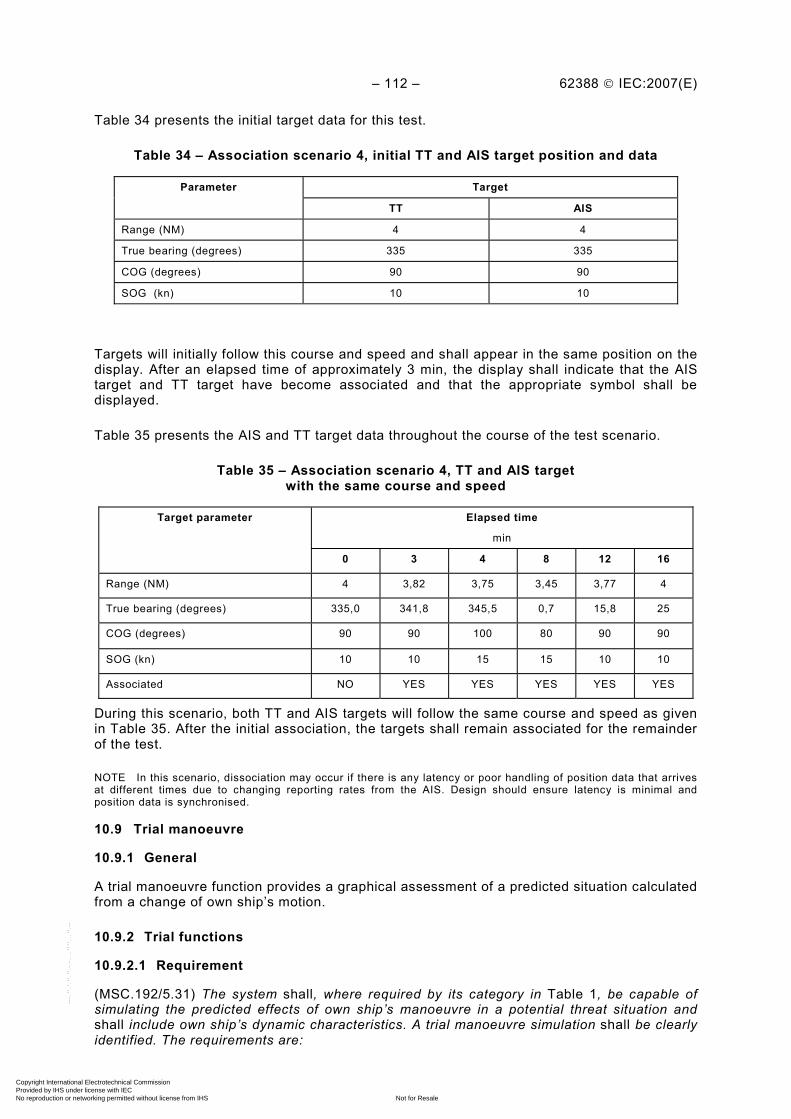
– 112 – 62388 © IEC:2007(E)
Table 34 presents the initial target data for this test.
Table 34 – Association scenario 4, initial TT and AIS target position and data
Target Parameter
TT AIS
Range (NM) 4 4
True bearing (degrees) 335 335
COG (degrees) 90 90
SOG (kn) 10 10
Targets will initially follow this course and speed and shall appear in the same position on the display. After an elapsed time of approximately 3 min, the display shall indicate that the AIS target and TT target have become associated and that the appropriate symbol shall be displayed.
Table 35 presents the AIS and TT target data throughout the course of the test scenario.
Table 35 – Association scenario 4, TT and AIS target with the same course and speed
Elapsed time
min
Target parameter
0 3 4 8 12 16
Range (NM) 4 3,82 3,75 3,45 3,77 4
True bearing (degrees) 335,0 341,8 345,5 0,7 15,8 25
COG (degrees) 90 90 100 80 90 90
SOG (kn) 10 10 15 15 10 10
Associated NO YES YES YES YES YES
During this scenario, both TT and AIS targets will follow the same course and speed as given in Table 35. After the initial association, the targets shall remain associated for the remainder of the test.
NOTE In this scenario, dissociation may occur if there is any latency or poor handling of position data that arrives at different times due to changing reporting rates from the AIS. Design should ensure latency is minimal and position data is synchronised.
10.9 Trial manoeuvre
10.9.1 General
A trial manoeuvre function provides a graphical assessment of a predicted situation calculated from a change of own ship’s motion.
10.9.2 Trial functions
10.9.2.1 Requirement
(MSC.192/5.31) The system shall, where required by its category in Table 1, be capable of simulating the predicted effects of own ship’s manoeuvre in a potential threat situation and shall include own ship’s dynamic characteristics. A trial manoeuvre simulation shall be clearly identified. The requirements are:
Copyright International Electrotechnical Commission Provided by IHS under license with IEC
Not for ResaleNo reproduction or networking permitted without license from IHS
--`,,```,,,,````-`-`,,`,,`,`,,`---
62388 © IEC:2007(E) – 113 –
– the simulation of own ship’s course and speed shall be variable; – a simulated time to manoeuvre with a countdown shall be provided;
– during simulation, target tracking shall continue and the actual target data shall be indicated; – trial manoeuvre shall be applied to all tracked targets and at least to all activated AIS
targets;
– trial manoeuvre shall be permitted in either ground or sea stabilised modes. – the user manual shall provide guidance for using the trial function.
10.9.2.2 Methods of test and required results
The methods of test and the required results are as follows:
a) confirm by observation and by document inspection that the trial manoeuvre function is provided as required by category of equipment in Table 1;
b) confirm by observation, that functions are provided to permit the user to simulate a change of own ship’s course and speed;
c) confirm by observation that there is provision for a function to simulate time-to-manoeuvre;
d) confirm by observation that during simulation, target tracking continues and actual target data is indicated;
e) confirm by observation that trial manoeuvre is applied to all tracked targets and at least to all activated AIS targets;
f) confirm by observation that own ship’s dynamic characteristics are included in the trial functionality in terms of turning performance and rate of change of velocity;
g) confirm by observation that the trial manoeuvre is applied graphically to all tracked targets and at least to all activated AIS targets, when relative vectors are selected, and that the vectors update as own ship’s course and dynamic characteristics alter (for example rate of turn), as appropriate;
h) confirm by observation that the trial manoeuvre readout and the graphics within the operational display area, including the “trial” symbol, are presented according to Annex J;
i) confirm by document inspection that guidance is provided for the trial manoeuvre and that there is an advisory note stating that better information is provided by using relative motion and sea stabilisation (water tracking).
11 Chart radar (optional classification)
11.1 General
Radar systems with chart functionality shall be tested in accordance with all of the requirements in this clause. Raster nautical charts (RNC) are not permitted for chart radar applications. Chart presentation requirements are according to this clause and Annex J and where applicable, there is a direct reference to clauses in IEC 61174 (ECDIS). A chart radar shall have presentation colours calibrated in accordance with Annex K (see also 6.5.1).
(MSC.191/7.2.2.1) ENC and other vector format electronic chart information may be displayed on a radar presentation. This shall be accomplished using layers of elements or objects selected from the electronic chart database. As a minimum, the elements of the ECDIS Standard Display (see IEC 61174) shall be available for individual selection by IMO display category or layer (for example IMO suggested viewing group), but not as individual objects. As far as practical and without significant compromise to the radar presentation and operation, electronic chart information shall be presented in accordance with MSC.191 and with the ECDIS standards as required by IMO Resolution A.817(19) and further specified in IHO S-52 and its appendices, and IEC 61174.
NOTE These requirements are addressed by IMO Resolution MSC.192(79), 5.33.1, 5.33.2, 5.33.3 and 5.33.7, and 11.1, 11.1.3 and 11.1.8 of this standard.
Copyright International Electrotechnical Commission Provided by IHS under license with IEC
Not for ResaleNo reproduction or networking permitted without license from IHS
--`,,```,,,,````-`-`,,`,,`,`,,`---
– 114 – 62388 © IEC:2007(E)
11.1.1 Chart operation and source
11.1.1.1 Requirement
(MSC.192/5.33.5) The display of radar information shall have priority. Chart information shall be displayed such that radar information is not substantially masked, obscured or degraded. Chart information shall be clearly perceptible as such.
(MSC.192/5.33.1) The radar system may provide the means to display ENC data and other vector chart information within the operational display area to provide continuous and real-time position monitoring. It shall be possible to temporarily remove the display of chart data by a single operator action and also to switch charts on and off.
(MSC.192/5.33.2) The ENC information shall be the primary source of chart information and shall comply with IHO relevant standards. The status of other chart information shall be identified with a permanent indication. Source and update information shall be made available to the user on demand.
11.1.1.2 Methods of test and required results
The methods of test and the required results are as follows:
a) confirm by document inspection that the category of equipment includes the optional chart functionality;
b) confirm by observation that the display of radar information has priority and that chart information is displayed so that radar information is not substantially masked, obscured or degraded. Chart information shall be clearly perceptible as such;
c) confirm by document inspection, that the user manual describes all available chart functionality and that it prohibits the use of RNC charts;
d) confirm by observation that there is a means to temporarily suppress the chart data by a single operator action (as defined in this standard), and that there is a facility to switch charts on and off. The suppress function may be combined with other functions;
e) confirm by observation that the status of other (non-ENC) chart information is identified with a permanent indication when charts are switched on;
f) confirm by observation that an indication of chart source and update information is available to the user.
11.1.2 Chart elements and availability
11.1.2.1 Requirement
(MSC.192/5.33.3) As a minimum, the elements of the ECDIS Standard Display shall be made available for individual selection by category or layer, but not as individual objects.
(MSC.191/6.2.3) The presentation of user-added charted information shall comply with the relevant IHO standards as far as practical.
The selected parts of SENC shall be displayed with no reduction of the information content. Specific information available shall not be displayed as generic information, for example a lateral buoy starboard shall not be shown as a generic buoy.
When chart elements are displayed, additional map information may be provided and in this case, shall be additional to and shall not conflict with, the chart presentation.
The system may provide a function to query information associated with chart objects.
Copyright International Electrotechnical Commission Provided by IHS under license with IEC
Not for ResaleNo reproduction or networking permitted without license from IHS
--`,,```,,,,````-`-`,,`,,`,`,,`---
62388 © IEC:2007(E) – 115 –
11.1.2.2 Methods of test and required results
The methods of test and the required results are as follows:
a) confirm by observation that the display of radar has priority and that chart information is displayed so that radar information is not substantially masked, obscured;
b) confirm by observation that control functions are provided to permit individual selection of chart features by category or layer, but not as individual object;
c) confirm by observation that the selected parts of SENC are displayed with no reduction of the information content for example a lateral buoy starboard shall not be shown as a generic buoy;
d) confirm by observation that if radar maps are displayed at the same time as ENC navigational information, the map information is additional to chart data, colours and graphics are differentiated and that the map symbols shall not degrade the chart presentation;
e) confirm by observation that if a facility has been provided to call up information associated with an object by cursor enquiry on its symbol, then the data shall be presented either outside of the operational display area, as a transparent presentation, or temporarily presented so as to limit masking or degrading the radar image within the radar operational display area. Where this facility is provided, the text shall not appear automatically whenever the object with which it is presented appears on the display. If depth information is displayed, it shall only be presented as it has been provided in the ENC and unchanged by additional attributes, for example tidal information;
f) confirm by observation that, as far as is practical, the presentation of user-added charted information complies with the relevant IHO standards.
11.1.3 Chart reference
11.1.3.1 General
Reference management is required to ensure that the information displayed is correlated and in the same reference and coordinate system.
11.1.3.2 Requirement (MSC.192/5.33.4) The chart information shall use the same reference and coordinate criteria as the radar / AIS, including datum, scale, orientation, CCRP and azimuth stabilisation mode.
11.1.3.3 Methods of test and required results
The methods of test and the required results are as follows:
a) confirm by observation that an indication is given if the input from the position sensor and ENC are of a different geodetic datum to WGS84;
b) confirm by document inspection that the user manual describes the way in which chart information uses the same reference, coordinate criteria and operational properties as the radar and AIS. Any limitations, including permitted range scales and modes, shall also be described in the user manual.
11.1.4 Primary chart information set
11.1.4.1 Requirement
The primary chart information set includes coastlines, own ship’s safety contour, dangers to navigation and fixed and floating aids to navigation, as further detailed in IMO Resolution A.817(19) Appendix 2, 1.1, 1.2, 1.3, 1.4 and 2.3 only. In areas where no ENC data is provided, “No data” shall be represented as a radar background. Annex J specifies the chart symbols and features to be used.
Copyright International Electrotechnical Commission Provided by IHS under license with IEC
Not for ResaleNo reproduction or networking permitted without license from IHS
--`,,```,,,,````-`-`,,`,,`,`,,`---
– 116 – 62388 © IEC:2007(E)
On user request, it shall be possible to select the primary chart information set by a dedicated primary control function.
The system shall provide a momentary control function to reduce on demand the presented chart information to coastlines only to check the matching of chart information to the radar image.
11.1.4.2 Methods of test and required results
The methods of test and the required results are as follows:
a) confirm by observation and by document inspection that the chart radar provides chart features and symbols that make up the primary chart information set, based on those defined in source documents of IMO Resolution A.817(19) and IEC 61174;
b) confirm by observation that it is possible to select the primary chart information set by a dedicated control function;
c) confirm by observation that areas where no chart data is provided is presented as a radar background;
d) confirm by observation that if provided, it is possible on user request to reduce the displayed chart content to coastlines only as long as the control function is pressed.
11.1.5 Chart stabilisation and chart redraw
11.1.5.1 Requirement
The equipment shall be capable of appropriately stabilising the radar image, tracked radar targets, reported AIS targets and vector chart information. The operating mode shall be clearly indicated. The vector chart information shall be available in north-up and course-up azimuth stabilised radar display modes and on all appropriate range scales. After a change of range scale or upon radar origin resetting, the new chart shall be displayed at its correct scale within 5 s and that after initiating the change, the chart display shall be suppressed and an indication given until the new chart is fully available.
11.1.5.2 Methods of test and required results
The methods of test and the required results are as follows:
a) confirm by observation of the EUT that ENCs are available in all appropriate azimuth stabilised operational modes and applicable radar range scales;
b) confirm by observation that the ENC information is maintained or re-introduced when the user switches to an alternative method of azimuth stabilization and that the selected mode is indicated;
c) confirm by observation that if the position sensor fails or is switched off, the vector chart information is removed automatically within 30 s. An alternative position information source or dead reckoning (DR) may be provided together with a clear indication;
d) confirm by observation that if the azimuth stabilization sensor fails or is switched off, the vector chart information is removed automatically within 30 s;
e) confirm by observation and by functional test, that while exercising position and rotation at 20°/s and 30 kn, for equipment complying with requirements for standard ships, or 20°/s and 70 kn for equipment complying with high speed craft requirement, for at least 20 consecutive scans. During these tests, the chart and radar images shall remain matched by visual assessment;
f) confirm by observation that after a change of range scale or upon radar origin resetting, the new chart is displayed at its correct scale within 5 s and that after initiating the change, the chart display is suppressed and an appropriate indication is given until the new chart is fully available.
Copyright International Electrotechnical Commission Provided by IHS under license with IEC
Not for ResaleNo reproduction or networking permitted without license from IHS
--`,,```,,,,````-`-`,,`,,`,`,,`---
62388 © IEC:2007(E) – 117 –
11.1.6 Chart position and latency
11.1.6.1 Requirement
The vector chart information shall be continuously displayed with minimal positioning and azimuth latency compared with the radar image.
11.1.6.2 Methods of test and required results
The methods of test and the required results are as follows:
a) confirm by measurement on the 24 NM range scale and using ENC information covering the area surrounding 70° N or 70° S, with own ship simulated position to 70° N or 70° S respectively. Measuring the range and bearing to 4 points in the chart by using the radar navigation tools (EBL/VRM and/or cursor), the 4 points are placed at a range between 10 NM and 24 NM and bearings of 45°, 135°, 225° and 315° with a tolerance of ± 5°. Using the radar tools, the measurements shall be within 0,25 NM in range and 1° in bearing as compared to those taken from the ENC information;
b) confirm by measurement and repeating the test in the azimuth stabilised modes while exercising position and rotation:
• at 20°/s and 30 kn, for equipment complying with requirements for non-high speed craft, or
• at 20°/s and 70 kn for equipment complying with high speed craft requirement, with a test conducted for at least 20 consecutive scans, that the chart and radar images
remain matched, by visual assessment, after each radar update. Using the radar navigation tools, the measurements, shall be within 0,25 NM in range and 1° in bearing as compared to those taken from the ENC information;
c) confirm by observation that the operating mode is indicated; d) confirm by measurement by repeating the test and stopping the rotation and after 1 min.
The SENC positioning latency shall not exceed one radar scan; e) confirm by observation that when in the non-stabilised mode while exercising position and
rotation (up to 20°/s), the chart presentation is disabled for the case of the misalignment between ENC information and radar image exceeding 7,5°;
f) confirm by observation when in the non-stabilised mode and when not changing course, the resulting misalignment between ENC information and radar image does not exceed 1,5°.
11.1.7 Matching and adjustment
11.1.7.1 Requirement
To compensate for any deviations between the chart image and the radar image through detectable causes, manual adjustment of the ENC shall be possible. Any manual adjustment shall be clearly indicated as long as it is activated. Resetting shall be possible in a simple manner.
The ENC information shall match, within appropriate tolerances, the range scale, orientation and projection of the radar information.
(MSC.191/7.1.2) If a radar image and an electronic chart are displayed together, the chart and the radar image shall use a consistent common reference point and match in scale, projection and orientation. Any offset shall be indicated.
(MSC.191/6.2.4) If the chart data derived from different scales appear on the display, the scale boundary shall be clearly indicated.
Copyright International Electrotechnical Commission Provided by IHS under license with IEC
Not for ResaleNo reproduction or networking permitted without license from IHS
--`,,```,,,,````-`-`,,`,,`,`,,`---
– 118 – 62388 © IEC:2007(E)
11.1.7.2 Methods of test and required results
The methods of test and the required results are as follows:
a) confirm by observation that manual adjustment of ENC information is available, that an indication is given, and that it is simple to reset the manual alignment;
b) confirm by observation that there is an indication when the ENC information is displayed at a larger scale than that contained in the ENC;
c) confirm by observation that the ENC matches the range, scale, orientation and projection of the radar information;
d) confirm by observation that if the chart data derived from different scales appear on the display, the scale boundary is clearly indicated.
11.1.8 Chart symbols, colours, and size
11.1.8.1 Requirement
(MSC.192/5.33.7) Symbols and colours shall comply with the performance standards for the Presentation of Navigation-related Information on Shipborne Navigational Displays adopted by the IMO (MSC.191(79)).
(MSC.191/5.4.2) Symbols used for the display of charted information shall comply with relevant IHO standards.
The equipment shall be tested by using the IHO test data sets, plain and encrypted S-57 data, for ECDIS or ENC plain and encrypted S-57 data.
Alternatively, electronic chart information may be presented in shades of grey. Where shades of grey are used, the shades shall be distinguishable between respective chart layers.
The displayed chart area shall be not greater than the area available for presenting the radar image.
Chart symbols, graphics, data areas and related graphics shall not mask, obscure or degrade the radar image.
11.1.8.2 Methods of test and required results
The methods of test and the required results are as follows:
a) confirm by observation that chart symbols and size are according to Annex J; b) confirm by observation that the display presentation of chart symbols are within the
SCAMIN / SCAMAX range as given in IEC 61174; c) confirm by observation that the colours of chart features are according to Annex J.
Contrasting colours for radar video shall be presented on a dark background. Display graphics and their colours shall not degrade chart or radar features;
d) confirm by observation that where grey is used for chart information (features), the shade is chosen to distinguish between the respective features and radar information;
e) confirm by observation that colour fill has been used where practical and appropriate, but not if the radar video is masked or degraded;
f) confirm by observation that the coastlines are drawn as a line, with the defined colours differentiating coastal areas;
g) confirm by observation that own ship’s safety contour is identified by a line and is further differentiated by colour shade;
h) confirm by observation that radar background and water surfaces in the ENC information shall be in the same basic colour;
Copyright International Electrotechnical Commission Provided by IHS under license with IEC
Not for ResaleNo reproduction or networking permitted without license from IHS
--`,,```,,,,````-`-`,,`,,`,`,,`---
62388 © IEC:2007(E) – 119 –
i) confirm by observation that day and night modes are provided and that the ENC day and night colours are selected simultaneously with the radar’s day/night colour mode. It is permitted to use the same colours for all light conditions;
j) confirm by observation that if the ENC information covers only part of the radar video area, the limits for ENC information are clearly indicated when ENC information is present;
k) confirm by observation that for borderlines between No-Data, Official-Data and Non-Official-Data, the appropriate line styles defined in IHO S-52 are used;
l) confirm by observation that for areas in which no data are provided, the NO-DATA-Pattern according to IHO S-52 is not used. The no-data area shall be shown as a radar background;
m) confirm by observation that if Non-Official-Data is used, a clear indication is given to the user according to IHO S-52;
n) confirm by observation that the displayed chart area is not greater than the area available for presenting the radar image.
11.1.9 Chart display size
11.1.9.1 Requirement
(MSC.192/6.2.3) The display sizes shall conform to those defined in Table 1 category 1 or 2, according to equipment category (see also 6.11.1).
11.1.9.2 Methods of test and results required
Confirm by measurement using a flexible transparent ruler that the operational radar and chart area within the bearing scale is compatible with Table 1 and 6.11.1.
11.1.10 Chart alarms and indications
11.1.10.1 Requirement
If an operational alarm for crossing a safety contour is provided, it shall conform to the ECDIS standard as defined in IEC 61174.
11.1.10.2 Methods of test and required results
The methods of test and the required results are as follows:
a) confirm by observation that an alarm is generated when the vessel is crossing the safety contour within the time specified by the user and according to IEC 61174;
b) confirm by observation that at all times, the safety contour is the one specified by the user or the next deeper contour if the specified one is not available. At a minimum, the user shall be informed by emphasizing the new safety contour. If the mariner does not specify a safety contour, the contour shall default to 30 m. If the safety contour specified by the user is not in the ENC, verify that the safety contour shown defaults to the next deeper contour;
c) confirm by observation that both the radar equipment and the ECDIS provides corresponding alarms, and verify that the safety contour set in the ECDIS is transferred to the radar.
11.1.11 Chart malfunction
11.1.11.1 Requirement
(MSC.192/5.33.6) A malfunction of the source of chart data shall not affect the operation of the radar / AIS system.
Copyright International Electrotechnical Commission Provided by IHS under license with IEC
Not for ResaleNo reproduction or networking permitted without license from IHS
--`,,```,,,,````-`-`,,`,,`,`,,`---

– 120 – 62388 © IEC:2007(E)
11.1.11.2 Methods of test and required results
Confirm by observation and documentation that as far as practical, the design meets the objective and where practical, check that a simulated malfunction of the source of chart data does not adversely affect the operation of the radar/AIS system or restrict the use of unrelated functionality.
11.1.12 Chart radar malfunction
11.1.12.1 Requirement
If the radar fails while ENC information is selected, a clear visual indication shall be given. The ENC information may be retained.
11.1.12.2 Methods of test and required results
The methods of test and the required results are as follows:
a) confirm by observation that when the radar signals are removed, an indication is provided; b) confirm by observation that the radar system generates an alarm.
11.2 Additional requirements for standalone radar with chart facilities
11.2.1 General
The following requirements for provision and updating of chart information are relevant for a standalone radar with chart facilities (i.e. the radar does not get pre-processed SENC information from an associated ECDIS, then the requirements of this subclause shall be applied.)
Where additional facilities are provided, then the appropriate requirements and tests from IEC 61174 shall apply.
11.2.2 Provision and updating of chart information
11.2.2.1 Requirement
If the chart radar has its own database, it shall comply with the relevant clauses in IEC 61174 for chart maintenance. For encrypted data, it shall fulfil the functional requirements and procedures of IHO S-63.
11.2.2.2 Methods of test and required results
The methods of test and the required results are as follows:
a) confirm that the update procedures in accordance with IEC 61174 are fulfilled; b) confirm that the requirements for encrypted data noted within IHO S-63 are fulfilled.
11.2.3 Content and structure of chart data
11.2.3.1 Requirement
The chart radar shall comply with the relevant clauses in IEC 61174.
11.2.3.2 Methods of test and required results
Verify that the EUT includes a chart library, which lists the ENC in the EUT by edition and date in accordance with IEC 61174.
Copyright International Electrotechnical Commission Provided by IHS under license with IEC
Not for ResaleNo reproduction or networking permitted without license from IHS
--`,,```,,,,````-`-`,,`,,`,`,,`---

62388 © IEC:2007(E) – 121 –
12 Ergonomic criteria (control functions and display)
12.1 General
The general requirements for operational controls are addressed in IEC 60945. Radar-specific control information is listed in Annex I of this standard.
12.1.1 Operational controls
12.1.1.1 Requirement
(MSC.192/6.1.1) The design shall ensure that the radar system is simple to operate. Operational controls shall have a harmonised user interface and shall be easy to identify and simple to use.
(MSC.192/6.1.2) The radar system shall be capable of being switched on or off at the main system radar display or at a related control position.
(MSC.192/6.1.3) The control functions may be dedicated hardware, screen accessed soft-keys, or a combination of these. The primary control functions shall be identified and shall be provided with an associated status indication, located in a consistent and intuitive position.
(MSC.192/6.1.5) The primary functions may also be operated from a remote operating position in addition to the main controls.
National Authorities and specific equipment categories (for example HSC) may require the provision of hardware controls for primary functions (see 12.1.2). The manufacturer shall submit any optional primary hardware controls for approval alongside the soft key functions. Dual operation, by soft key or hardware controls is permitted.
As far as practical, the information within each control-related information group shall be collocated on the radar screen.
12.1.1.2 Methods of test and required results
The methods of test and the required results are as follows:
a) confirm by document inspection, the category of equipment submitted for testing and the related requirements for that category;
b) confirm by document inspection that any optional hardware controls, including remote control modules, have been submitted and tested with the main equipment;
c) confirm by observation that primary control functions are instantly available. In the case of a soft key function, the use of a cursor and a single soft key is permitted. Check that hardware controls, where provided, have a dedicated or a related function;
d) confirm by observation that the control functions are provided with an associated status indication or description, as appropriate. Any soft keys provided shall be located adjacent to the function status indication;
e) confirm by observation that the location of the on/off control for an individual radar position and its associated radar sensor (transceiver and antenna) is conspicuous and easily accessible under all operational and ambient light conditions. Check that the radar on/off control is normally mounted at the radar display or at a related and logical position;
f) confirm by document inspection of submitted documentation, that the manufacturer has conducted a user performance evaluation with a representative user. The report shall demonstrate that the operation of the radar system can satisfy the safety of navigation requirements of the current version of the IMO STCW code (Standards of Training, Certification and Watch-keeping for Seafarers) radar training course;
Copyright International Electrotechnical Commission Provided by IHS under license with IEC
Not for ResaleNo reproduction or networking permitted without license from IHS
--`,,```,,,,````-`-`,,`,,`,`,,`---
– 122 – 62388 © IEC:2007(E)
g) confirm by observation and document inspection that the radar control display information is presented in logical functional groups according to the ergonomic requirements of IEC 60945. As far as practical, the information within each control-related information group shall be collocated on the radar screen.
12.1.2 Primary controls
12.1.2.1 Requirement
(MSC.192/6.1.4) The following are defined as primary radar control functions and shall be easily and immediately accessible:
Radar standby / run (transmit), range scale selection, gain, tuning function (if applicable), anti-clutter rain, anti-clutter sea, AIS function on/off, alarm acknowledge, cursor, a means to set EBL/VRM, display brightness and acquisition of radar targets.
12.1.2.2 Methods of test and required results
The methods of test and the required results are as follows:
a) confirm by observation that the specified primary control functions are available. For the purposes of this standard, the listed functions shall be directly accessible and immediately effected by dedicated controls or by primary access on the display within the user dialogue area. Alternative solutions which meet the functional requirements may be provided;
b) confirm by observation that if these functions are provided as soft keys, that any optional hardware-based control panels provided shall be tested with the EUT;
c) confirm by observation that where discrete controls are available for the EBL and VRM, they are ergonomically positioned for simultaneous operation, on the left and right hand side respectively;
d) confirm by observation that the control functions are logically grouped in conformance to the requirements of IEC 60945 and that the grouping, as far as practical, conforms to Annex I of this standard.
12.1.3 Control properties
12.1.3.1 Requirement
It shall be possible to locate and control the panel illumination (where applicable), monitor brightness/contrast (as applicable) and on/off by tactile and/or visual means. If panel illumination is provided, the illumination shall be even and supportive of night vision. The following functions shall be continuously variable or in small, quasi-analogue steps:
– monitor brightness/contrast; – VRM, EBL; – cursor; – tuning (if manual); – rain, gain, sea. The illumination of controls shall be in accordance with IEC 60945.
12.1.3.2 Methods of test and required results
The methods of test and the required results are as follows:
a) confirm by observation that listed controls can be located in a dark environment by tactile and/or visual means;
b) confirm by observation in a darkened environment, ranging from zero light to dusk conditions, that the illumination (where provided) meets the requirements;
Copyright International Electrotechnical Commission Provided by IHS under license with IEC
Not for ResaleNo reproduction or networking permitted without license from IHS
--`,,```,,,,````-`-`,,`,,`,`,,`---
62388 © IEC:2007(E) – 123 –
c) confirm by observation that the illumination complies with IEC 60945.
13 Interfacing
13.1 General
The equipment shall provide inputs for interfacing sensors and related navigation systems, and output interfacing to provide information for other navigation displays.
13.2 Input interfacing
13.2.1 Input data
13.2.1.1 Requirement
(MSC.192/8.1) The radar system shall be capable of receiving the required input information from:
– a gyro-compass or transmitting heading device (THD);
– a speed and distance measuring equipment (SDME); – an electronic position fixing system (EPFS); and
– an automatic identification system (AIS); or – other sensors or networks providing equivalent information acceptable to the IMO.
(MSC.192/8.1) The radar shall be interfaced to relevant sensors required by these performance standards in accordance with recognised international standards.
13.2.1.2 Methods of test and required results
The methods of test and the required results are as follows:
a) confirm by document inspection that there is provision for receiving the required input information from the sensors listed;
b) confirm by document inspection and by observation, that there is a means to configure the input data to provide compatibility with the source. The interface configuration shall not be accessible in an operational mode and shall be protected (for example by a password or hardware device) from inadvertent adjustment;
c) confirm by document inspection and by observation that the parameters are retained either in hardware (for example by links) or in non-volatile memory and that the user manual describes how the parameters can be transferred when relevant hardware is replaced in the equipment;
d) confirm by document inspection that there is provision for IEC 61162 interfaces and that these are described in the manufacturer’s documentation;
e) confirm by measurement that a sample of each type of serial interface provided is tested with a simulated signal. A list of relevant messages is included in Annex H;
f) if no suitable IEC 61162 interface is available, an alternative appropriate interface may be used and shall be tested to the manufacturer’s information. Where alternative interfaces are provided, check that the application, the basic protocol and the connectivity are explained in the user and installation manuals.
13.2.2 Input quality, integrity and latency
13.2.2.1 Requirement
(MSC.192/8.2.1) The radar system shall not use data indicated as invalid. If input data is known to be of poor quality, this shall be clearly indicated.
Copyright International Electrotechnical Commission Provided by IHS under license with IEC
Not for ResaleNo reproduction or networking permitted without license from IHS
--`,,```,,,,````-`-`,,`,,`,`,,`---

– 124 – 62388 © IEC:2007(E)
(MSC.192/8.2.2) As far as is practical, the integrity of data shall be checked prior to its use by comparison with other connected sensors or by testing to valid and plausible data limits.
(MSC.192/8.2.3) The latency of processing input data shall be minimised.
13.2.2.2 Methods of test and required results
The methods of test and the required results are as follows:
a) confirm by observation of the EUT that when a serial message with invalid data is provided, the radar system does not use the data for any calculation and that the information is indicated as invalid;
b) confirm by observation where appropriate and as far as is practical, that the radar system compares input data against implausible limits. Verify where possible, that the design checks the integrity of data by comparison with related data from other sensors. For example, if two position inputs are available, these can be compared.
NOTE The design of the radar system should, where practical, ensure that the latency of processing an input serial message is less than 1 scan or 1 s, whichever is the lesser.
13.3 Output interfacing
13.3.1 Output format
13.3.1.1 Requirement
(MSC.192/8.3.1) Where practical, information provided by any radar output interface to other systems shall be in accordance with international standards (publication IEC 61162).
13.3.1.2 Methods of test and required results
Confirm by measurement that appropriate output interfaces conform to the IEC 61162 series, in terms of message content and hardware compatibility. In this case, “appropriate” means where practical and available. Monitor sample output messages to confirm conformity.
13.3.2 Output target data
13.3.2.1 Requirement
The radar system shall provide target data via a serial interface for transfer to other navigational equipment.
13.3.2.2 Methods of test and required results
The methods of test and the required results are as follows:
a) confirm by observation that the track table conforms to IEC 61162 and that all data is correctly identified within the output message;
b) confirm by observation that where the equipment shares target data with similar equipment, target data is coordinated so that each target has a unique reference. Using the target simulator, verify that a duplicated target message is identified and shares the same identity as the same target in the output data. Data content shall be as listed in Annex H;
c) confirm by observation and using the target simulator, that the EUT is capable of providing a target table message for the maximum number of tracked targets and activated AIS targets for that category of equipment.
NOTE The target data message is not time-referenced (time-stamped) and is unsuitable for external navigation displays to provide target association functions unless associated targets are expressly identified within the data message. Navigation displays should refer to Annex A for guidance on the use of target data. The methods given in IEC 61162-1 are too slow for AIS data to be transmitted.
Copyright International Electrotechnical Commission Provided by IHS under license with IEC
Not for ResaleNo reproduction or networking permitted without license from IHS
--`,,```,,,,````-`-`,,`,,`,`,,`---

62388 © IEC:2007(E) – 125 –
13.3.3 VDR interface
13.3.3.1 Requirement
(MSC.192/8.3.2) The radar system shall provide an output of the display data for the voyage data recorder (VDR).
13.3.3.2 Methods of test and required results
The methods of test and the required results are as follows:
a) confirm by document inspection that a separate and dedicated output is available, replicating the display data interface, at least in analogue RGB format;
NOTE The current RGB output has a limited resolution, typically up to 1280 x 1024 pixels. Future presentations are expected to exceed that resolution and may need to be addressed with a digital interface as specified in c).
b) confirm by observation that the radar RGB output complies with the image test defined in the VDR test standard, IEC 61996;
c) confirm by document inspection that where displays with high bandwidths are used or the display performance is not compatible with the RGB format, the radar processor provides either a dedicated output complying with the digital interface meeting the electrical specifications of a Digital Visual Interface, DVI (Digital Display Working Group, DDWG) or an Ethernet Interface. The Ethernet Interface shall support digital file transfers of at least one screen capture in 15 s. A lossless graphic algorithm shall be used;
d) confirm by document inspection that if an Ethernet output is provided to convey the display files to a voyage data recorder, the data format complies with a digital Ethernet Interface according to the IEC 61162 series or Annex H.2 in this standard;
e) confirm by observation that the radar digital output complies with the image test defined in the VDR standards, IEC 61996;
f) confirm by observation or by document inspection of the design, that a fault condition on the output to the VDR (for example a short circuit on the output) does not degrade the performance of the radar display;
g) confirm by observation that the VDR output cannot be deactivated by the user; h) confirm by document inspection that the instructions for connecting a VDR to the radar
system are included in the installation manual.
14 Design, servicing and installation
14.1 General
The following design and servicing information provides guidelines to support maximum equipment availability and serviceability.
14.1.1 Fault diagnosis and servicing
14.1.1.1 Requirement
(MSC.192/7.1.1) As far as is practical, the radar system shall facilitate simple fault diagnosis and maximum availability.
(MSC.192/7.1.2) The radar system shall include a means to record the total operational hours for any critical components with a limited life.
(MSC.192/7.1.3) The documentation shall describe any routine servicing requirements and shall include details of any restricted life components and their advised replacement.
Copyright International Electrotechnical Commission Provided by IHS under license with IEC
Not for ResaleNo reproduction or networking permitted without license from IHS
--`,,```,,,,````-`-`,,`,,`,`,,`---

– 126 – 62388 © IEC:2007(E)
14.1.1.2 Methods of test and required results
The methods of test and the required results are as follows:
a) confirm by document inspection that the user manual provides a top level guide for simple fault diagnosis and guidance to maintain maximum equipment availability;
b) confirm by document inspection that the user manual includes a list of components that have a limited (short) operational life for example, magnetrons and other thermionic devices, mechanical components for example, belts, brushes, motors, fans, lubrication for gearboxes, and instructions to service these items;
c) confirm by document inspection that the equipment provides details of total operational hours for those components with a limited life, such as the magnetron, and that information for their recommended replacement or maintenance is included in the user manual. The operational hours of a limited life component shall be capable of being displayed at a related display or with an alternative indication;
d) confirm by observation and by document inspection that an indication is provided, or as a minimum included in the user manual, that there is a recommendation that specific components having a declared limited operational life shall be replaced.
14.1.2 Display design
14.1.2.1 Requirement
(MSC.192/7.2) The physical requirements for the display device shall meet those specified in the performance standards for the Presentation of Navigation-related Information on Shipborne Navigational Displays adopted by the IMO (MSC.191(79)), and those specified in Table 1 and Clause 6 of this standard.
All critical equipment, system and installation related parameters shall be retained in a non-volatile and transferable memory, or the equivalent.
14.1.2.2 Methods of test and required results
The methods of test and the required results are as follows:
a) confirm by document inspection and by measurement using a ruler that the display size conforms to Table 1 in this standard for the category of equipment submitted;
b) verify that the display is according to Clause 6 for all physical requirements; c) confirm by document inspection of the relevant equipment manuals, that there is provision
for the retaining of critical parameters (for example installation parameters). Retained parameters shall be listed within the manufacturer’s manual. The documentation shall describe that when a relevant replacement module is fitted, the parameters are transferable from the replaced module. (Some of these requirements are verified elsewhere in this standard.) Retained information may include, for example installation parameters, sensor parameters, interface parameters, blank sector limits, maps, and default display configurations.
14.2 Transceiver design
14.2.1 General
The transceiver includes the generation of microwave energy and the transmission of that energy via an appropriate transmission line. The receiver system typically shares that transmission line and provides a signal representing the radar image. The transceiver may be down-mast or combined with an up-mast unit. The transceiver system may be non-coherent or coherent.
Copyright International Electrotechnical Commission Provided by IHS under license with IEC
Not for ResaleNo reproduction or networking permitted without license from IHS
--`,,```,,,,````-`-`,,`,,`,`,,`---
62388 © IEC:2007(E) – 127 –
14.2.2 Sector blanking
14.2.2.1 Requirement
(MSC.192/7.3) The equipment shall provide a sector blanking (mute) facility to inhibit the transmission of radar energy over a preset sector. The blanked (muted) sector shall be set up on installation and the values retained in transferable non-volatile memory. An indication of sector mute status shall be available and provided on the display.
14.2.2.2 Methods of test and required results
The methods of test and the required results are as follows:
a) confirm by observation that a transmission sector blanking (mute) facility is provided and that there is an indication to identify the sector and the status of the function;
b) confirm by observation that the sector blanking (mute) function can be set up in a non-operational equipment menu;
c) confirm by document inspection that the method of adjustment is described in the manufacturer’s documentation, and ensure that access is via a protected menu;
d) confirm by observation that the sector blanking (mute) can be set and automatically applied for each selected radar sensor and that these parameters are retained in a transferable non-volatile memory.
14.3 Antenna design
14.3.1 Requirement
(MSC.192/7.4.1) The antenna shall be designed to start operating and to continue to operate in relative wind speeds likely to be encountered on the class of ship on which it is installed.
(MSC.192/7.4.2) The combined radar system shall be capable of providing an appropriate information update rate for the class of ship on which it is installed. Equivalent tests for new technology shall be conducted in agreement with the test authority.
14.3.2 Methods of test and required results
The methods of test and the required results are as follows:
a) the antenna/pedestal combination shall be placed in a wind tunnel capable of producing an air stream of up to 100 kn. The largest antenna for the frequency band submitted shall be used. The antenna motor shall be provided with a power source at its nominal voltage and frequency. Where appropriate, only the antenna/pedestal combination shall be used in this test;
b) confirm by observation, that in the case of a rotating antenna, the scan is continuous and in a clockwise direction when viewed from above and automatic through 360° in azimuth, and with a rotation rate adequate for the category of equipment;
c) confirm by observation that the antenna starts and operates satisfactorily in continuous relative speeds of 100 kn;
d) check by document inspection and by measurement that the radar system provides an update rate adequate for the class of ship and category against which it is submitted. The update rate shall be sufficient to ensure that all tracking and signal processing functions operate correctly, and the user is provided with adequate situation awareness. In the case of a conventional antenna and radar system, the recommended minimum rate of rotation is 20 rpm for standard ships and 40 rpm for HSC.
NOTE Slower antenna rotation rates may be provided for higher range scales or to provide compatibility with novel processing techniques, provided that update-dependent requirements are met. For example a system with a back-to-back antenna assembly could be submitted and could provide equivalent performance at a lower rotation rate. Equivalence to these rotation rates may be submitted, demonstrated and tested by the test authority.
Copyright International Electrotechnical Commission Provided by IHS under license with IEC
Not for ResaleNo reproduction or networking permitted without license from IHS
--`,,```,,,,````-`-`,,`,,`,`,,`---
– 128 – 62388 © IEC:2007(E)
NOTE Alternative technologies may provide other solutions in which case the manufacturer should describe equivalence and demonstrate conformance to the relevant requirements in this standard.
14.4 Inter-switched and multiple radars
14.4.1 General
The radar system shall be designed and configured to maximise radar availability.
14.4.2 System safeguards
14.4.2.1 Requirement
(MSC.192/5.35.1) The system design shall safeguard against single point system failure. A fail-safe condition shall be applied in the event of an integration failure.
In the event of a single point failure, it shall be possible to configure the multiple radar system to enable each of the radars to operate as a standalone system.
Where two radars are required to be carried, they shall be so designed, configured and installed that each radar can be operated individually and both be operated simultaneously, without being dependent upon one another. Where provided, the flexibility and availability shall be improved by the inter-switching facility and the failure of either radar shall not cause the other radar to be adversely effected.
14.4.2.2 Methods of test and required results
The methods of test and the required results are as follows:
a) confirm by document inspection that the user manual describes how system safeguards against single point failure and, how a fail-safe condition is automatically, or can be manually, applied in the event of a failure, to permit standalone operation;
b) confirm by document inspection, that two radars may be configured and installed so that they can operate individually and simultaneously without any critical interdependence. Configuration guidelines and non-dependency shall be described in the user manual;
c) confirm by observation that when simulating a single point failure within the inter-switch system, each of the radars is able to operate as a standalone system.
14.4.3 Combining radar
14.4.3.1 Requirement
(MSC.192/5.35.2) Where the combining of radar signals from multiple sensors is provided, the source and any processing or combination of radar signals from two or more radar sensors shall be indicated.
It is permitted to present radar signals from more than one radar sensor on a single display. The combining of radar signals from multiple sensors shall not degrade performance and the failure of one sensor shall not disable signals from other sensors from being displayed.
14.4.3.2 Methods of test and required results
Where the radar system submitted is capable of processing or combining the signals from two separate sources, these additional tests shall apply:
a) confirm by document inspection, if the manufacturer has submitted a radar system which is capable of processing and/or combining the radar signals from two or more sensors. Establish if the purpose of combining the signals is to provide radar coverage over two sectors, improve performance by dual radar coverage of a common sector, or both;
Copyright International Electrotechnical Commission Provided by IHS under license with IEC
Not for ResaleNo reproduction or networking permitted without license from IHS
--`,,```,,,,````-`-`,,`,,`,`,,`---
62388 © IEC:2007(E) – 129 –
b) confirm by observation that the control of anti-clutter rain, anti-clutter sea, gain and tuning for each radar sensor is independent and that their status is indicated on the display;
c) confirm by observation that each radar sensor has position compensation with respect to the CCRP;
d) confirm by document inspection that the interfacing, commissioning and setting-up procedure are clearly described in the installation and/or user documentation;
e) confirm by document inspection that if provided, the manufacturer’s manual describes operation, advantages and limitations of this system;
f) confirm by document inspection of the equipment test certification, that each radar system has been approved independently to this standard;
g) where radar coverage overlaps, confirm that signals from the two sensors share a common position on the display position. The two signals shall as a minimum partially overlap;
h) where radar sensors cover different sectors, confirm that the presentation is seamless or that the limits of sectors are indicated, for example by the absence of system noise;
i) confirm by observation, that where a combined or pre-processed system is submitted, the performance of the resulting radar system is not inferior to that required in these radar test standards;
j) confirm by analytical evaluation, that the failure of one radar sensor does not degrade the operation of other radar sensors.
14.4.4 Multiple radar system status
14.4.4.1 Requirement
(MSC.192/5.35.3) The system status for each display position and for each radar sensor shall be available.
14.4.4.2 Methods of test and required results
Confirm by observation that the status for the radar system, as applicable for each display position, is indicated. The indications shall be permanent and shall inform the user if the display or system is:
• a master display, for example to a radar sensor;
• a slave display to another display. This should be identified as for example “Radar 1” or “Display A”;
The display reference may be identified either on, or adjacent to the presentation.
14.5 Multiple operational displays
14.5.1 Additional information and conformity
The displays may be configured to present radar, chart and other navigation information.
14.5.1.1 Requirement
(MSC.191/7.1.1) If the display equipment is capable of supporting the presentation of multiple functions, then there shall be a clear indication of the primary function supported by the presentation (for example, radar, ECDIS).
(MSC.191/7.4.1) The user may configure a presentation for the task-in-hand. The presentation may include radar and/or electronic chart information, in combination with other navigation or ship related data or information. When not fully compliant with the radar or ECDIS, Performance Standards, such a presentation shall be identified as an auxiliary presentation.
Copyright International Electrotechnical Commission Provided by IHS under license with IEC
Not for ResaleNo reproduction or networking permitted without license from IHS
--`,,```,,,,````-`-`,,`,,`,`,,`---

– 130 – 62388 © IEC:2007(E)
(MSC.191/7.4.2) As far as practical, the presentation of any radar and/or ECDIS related functions shall be compliant with the requirements of the relevant Performance Standards and the Presentation Standard, MSC.191(79), with the exception of size requirements for the operational area. Chartlets or windows of radar information may be presented along with other information associated with the task-in-hand.
14.5.1.2 Methods of test and required results
The methods of test and the required results are as follows:
a) confirm by observation that if the display equipment is capable of supporting the presentation of multiple functions, then there shall be a clear indication of the primary function supported by the presentation. If a display is not compliant with this standard it shall be identified as an auxiliary display;
b) confirm by observation that, as far as practical, the display presentation is in accordance with the relevant performance standards.
14.6 Safety – antenna and radiation
14.6.1 General
Basic safety requirements relating to radiation and antenna rotation are defined.
14.6.2 Antenna radiation and rotation
14.6.2.1 Requirement
Radio frequency radiation from the antenna shall be possible only when the beam is scanning, except that override facilities may be provided for maintenance purposes. A means shall be provided to prevent antenna rotation during servicing.
14.6.2.2 Methods of test and required results
The methods of test and the required results are as follows:
a) confirm by observation that, as appropriate to the technology, transmission is only enabled when the antenna is scanning. An override may be provided for maintenance purposes. The means of isolation may be either located on the turning unit, may be available as a separate switch, or by the removal of clearly identified equipment fuses;
b) confirm by inspection of the documentation that the means to prevent the antenna from rotating and the override function are described in the user manual.
14.6.3 Microwave radiation levels
14.6.3.1 Requirement
The maximum distances from the antenna at which radio frequency radiation levels of 100 W/m², 50 W/m² and 10 W/m² can be expected shall be included in the equipment manual.
14.6.3.2 Methods of test and required results
The methods of test and the required results are as follows:
a) confirm by document inspection that the radiation levels at specified distances are available in the user and installation manuals;
b) confirm by measurement the radiation levels at the quoted distances are correct or are within the manufacturer’s quoted measurements.
Copyright International Electrotechnical Commission Provided by IHS under license with IEC
Not for ResaleNo reproduction or networking permitted without license from IHS
--`,,```,,,,````-`-`,,`,,`,`,,`---

62388 © IEC:2007(E) – 131 –
15 Alarms and failures
15.1 General
The radar shall provide alarms and indications to signify total or partial failure. Presentation of alarms is addressed in Clause 6.
15.1.1 Alarms and indications
15.1.1.1 Requirement
(MSC.192/5.34) Alarms and indications shall comply with the performance standards for the Presentation of Navigation-related Information on Shipborne Navigational Displays, adopted by the IMO.
15.1.1.2 Methods of test and results required
Verify that the presentation of alarms and indications is in accordance with MSC.191(79) (see 6.9).
15.1.2 Alarm outputs
15.1.2.1 Requirement
(MSC.192/8.3.3) At least one normally closed isolated contact shall be provided with the radar system for indicating failure of the radar system.
(MSC.192/8.3.4) The radar shall have a bi-directional interface to facilitate communication so that alarms from the radar can be transferred to external systems and audible alarms from the radar can be muted or acknowledged from external systems. The interface shall comply with relevant international standards.
NOTE Critical alarms such as CPA/TCPA should not be acknowledgeable from external systems. The manufacturer should provide a list of critical alarms which cannot be acknowledged from external equipment.
15.1.2.2 Methods of test and required results
The methods of test and the required results are as follows:
a) confirm by document inspection that an isolated pair of normally closed contacts is available to indicate the failure of the radar and that the contacts are rated to switch at least 100 mA into a resistive load;
b) confirm by observation that the relay contacts open by simulating failures, for example of a transceiver, antenna rotation (as applicable), power supply or processor;
c) check by observation that a bidirectional alarm communication interface, compliant with relevant IEC 61162 standards, is provided to communicate alarm messages with external systems. Verify that radar system alarms can be transferred to external systems, that all audible alarms can be muted from external systems and that the radar can provide output to acknowledge external alarm panels;
d) confirm by observation that the radar provides an indication when any input from an external sensor is absent or invalid. Confirm by observation that the radar repeats any status alarms or status messages concerning the quality of the input data from its external sensors;
e) confirm by observation that when an input from an external sensor is removed, an indication is provided. Repeat the test for an invalid input and confirm that an invalid indication is presented;
f) confirm by observation that it is not possible to acknowledge the radar critical alarms such as CPA and TCPA from external equipment without displaying the reason/cause for the alarm.
Copyright International Electrotechnical Commission Provided by IHS under license with IEC
Not for ResaleNo reproduction or networking permitted without license from IHS
--`,,```,,,,````-`-`,,`,,`,`,,`---
– 132 – 62388 © IEC:2007(E)
15.1.3 Picture freeze
15.1.3.1 Requirement
(MSC.192/5.34.1) A means shall be provided to alert the user of “picture freeze”.
15.1.3.2 Methods of test and required results
The methods of test and the required results are as follows:
a) confirm by document inspection the user manual describes that when a picture freeze occurs, the user is alerted whatever the basic cause may be. The design shall have a provision (for example by dynamic indication) to verify that the display is operational, that the graphic processor has not failed and that the display radar content is being updated by real time information, for example by the radar content or clutter being visibly updated;
b) confirm by document inspection that the user manual describes a picture freeze failure condition and any associated indications for that condition.
15.1.4 Sensor failure alarm
15.1.4.1 Requirement
(MSC.192/5.34.2) Failure of any signal or sensor in use, including; gyro, log, azimuth, video, sync and heading marker, shall be alarmed. System functionality shall be limited to a fall back mode or in some cases, the display presentation shall be inhibited.
15.1.4.2 Methods of test and required results
Confirm by inspection that the principal signal and sensor failure modes are described in the user manual. Fallback modes are tested in 15.2.
15.2 Backup and fallback arrangements
15.2.1 Requirement
(MSC.192/9) In the event of partial failures and to maintain minimum basic operation, the fallback arrangements listed below shall be provided. There shall be a permanent indication of the failed input information.
15.2.2 Failure of heading information (azimuth stabilisation)
15.2.2.1 Requirement
(MSC.192/9.1.1) The equipment shall operate satisfactorily in a non-stabilised head-up mode.
(MSC.192/9.1.2) The equipment shall switch automatically to the non-stabilised head up mode within 1 minute after the azimuth stabilisation has become ineffective.
(MSC.192/9.1.3) If automatic anti-clutter processing could prevent the detection of targets in the absence of appropriate stabilisation, the processing shall switch off automatically within 1 minute after the azimuth stabilisation has become ineffective.
(MSC.192/9.1.4) An indication shall be given that only relative bearing measurements can be used.
15.2.2.2 Methods of test and required results
The methods of test and the required results are as follows:
a) confirm by observation that the sequence of requirements is met;
Copyright International Electrotechnical Commission Provided by IHS under license with IEC
Not for ResaleNo reproduction or networking permitted without license from IHS
--`,,```,,,,````-`-`,,`,,`,`,,`---

62388 © IEC:2007(E) – 133 –
b) confirm by observation that all functions reliant on azimuth stabilisation are disabled and that there is an indication that only relative bearings can be used.
15.2.3 Failure of speed through the water information
15.2.3.1 Requirement
(MSC.192/9.2) A means of manual speed input shall be provided and its use clearly indicated.
15.2.3.2 Methods of test and required results
The methods of test and the required results are as follows:
a) confirm by observation that manual speed is provided and its use clearly indicated; b) confirm by observation that the speed is adjustable over the range of at least 1 kn to
70 kn; c) confirm by measurement of a simulated speed that the speed is accurate to within ± 2 %
or 1 kn.
15.2.4 Failure of course and speed over ground information
15.2.4.1 Requirement
(MSC.192/9.3) The equipment may be operated with course and speed through the water information.
15.2.4.2 Methods of test and required results
The methods of test and the required results are as follows:
a) confirm by observation that any function reliant on own ship COG and SOG is inhibited; b) confirm by observation that if the facility is provided, the radar system identifies the failure
of COG and SOG and that the system automatically reverts to speed through water; c) confirm by observation that the user is alerted to the change in stabilisation by simulating
a failure of velocity over ground.
15.2.5 Failure of position input information
15.2.5.1 Requirement
(MSC.192/9.4) The overlay of chart data and geographically referenced maps shall be disabled if only a single reference target is defined and used, or the position is manually entered.
15.2.5.2 Methods of test and required results
Confirm by observation that when chart data or geographically referenced maps are in use, they are disabled if only a single reference target is defined or if the position is manually entered.
15.2.6 Failure of radar video input information
15.2.6.1 Requirement
(MSC.192/9.5) In the absence of radar signals, the equipment shall display target information based on AIS data. A frozen radar picture shall not be displayed.
15.2.6.2 Methods of test and required results
The methods of test and the required results are as follows:
Copyright International Electrotechnical Commission Provided by IHS under license with IEC
Not for ResaleNo reproduction or networking permitted without license from IHS
--`,,```,,,,````-`-`,,`,,`,`,,`---

– 134 – 62388 © IEC:2007(E)
a) confirm by observation that it is not possible to display a frozen radar picture when the radar video signal is disconnected or disabled;
b) confirm by observation that in the absence of radar video, it is possible to display target information based on AIS data;
c) confirm by observation that a user message is provided to alert the user of the failure status and any resulting limitations that apply for collision avoidance assessment.
15.2.7 Failure of AIS input information
15.2.7.1 Requirement
(MSC.192/9.6) In the absence of AIS signals, the equipment shall display the radar video and target database.
15.2.7.2 Methods of test and required results
Confirm by observation that, in the absence of AIS signals, the radar continues to provide radar video and target information and that functionality is not impaired.
15.2.8 Failure of an integrated or networked system
15.2.8.1 Requirement
(MSC.192/9.7) The equipment shall be capable of operating equivalent to a stand-alone system.
15.2.8.2 Methods of test and required results
The methods of test and the required results are as follows:
a) confirm by observation and/or by inspection of the documentation that, if appropriate with the submitted equipment, means is provided to permit the radar to operate as a standalone system;
b) confirm by document inspection that the documentation describes changing the configuration to a stand-alone system.
16 Environmental testing
16.1 General
The equipment shall comply with the general requirements of IEC 60945, including temperature, vibration, corrosion (by inspection of materials used), EMC and ergonomics.
The environmental category of each individual module of the radar system shall be identified as being exposed (above deck) or protected (below deck).
16.1.1 Testing to IEC 60945
16.1.1.1 Requirement
The equipment under test shall be set to work and confirmed to be operational by the application of basic performance checks and a performance test. Testing to IEC 60945 general requirements shall then commence.
The “performance check” shall as a minimum be conducted on a system with the antenna replaced by a dummy load and using simulated ship sensors for log, gyro and AIS connected so that the gain and tuning response can be checked and the following can be conducted with own ship in simulated motion. The magnetron current (or transmission equivalent) shall be
Copyright International Electrotechnical Commission Provided by IHS under license with IEC
Not for ResaleNo reproduction or networking permitted without license from IHS
--`,,```,,,,````-`-`,,`,,`,`,,`---

62388 © IEC:2007(E) – 135 –
monitored and the receiver noise, as presented shall be set to an operational level at room temperature.
16.1.1.2 Methods of test and required results
Verify that the EUT conforms to the standard general requirements by observing that, following each test, a performance check confirms that there is no external indication of damage and there is no detectable degradation in functional performance:
a) confirm by observation that the cursor control responds and operates smoothly in each axis;
b) confirm by observation that each of the hardware controls and a sample of the software control functions (as provided confirm that they continue to be functional during the environmental condition);
c) confirm by measurement and observation that when exercising the target simulation facility described in 17.1.1.1 or the tracking scenario in 10.3.13, the solution is correct;
d) confirm by observation that when switching through the range scales during the tracking scenario, the trails are retained as required;
e) confirm by measurement that the radar transmission (for example magnetron current) does not vary by more than ± 20 % over the operating temperature range;
NOTE Allow a settling time of at least 30 min.
f) confirm by observation that the system noise level, as presented does not appreciably change over the operating temperature range.
NOTE The appropriate use of ‘performance check’ or ‘performance test’ (as specified in 16.1.1) during testing should be as required in IEC 60945 for the specific environmental tests.
16.2 Additional environmental tests
16.2.1 General
In addition to the standard IEC 60945 requirements, and for HSC radar only, the antenna and its mounting requires an additional shock/vibration test. The shock test provides a simulation in which the resonant responses, comparable with those likely to be experienced in practice in the operational environment, can be reproduced in the test laboratory. The antenna and its mounting shall be designed to withstand the test without external indications of damage or subsequent degradation in performance. A performance check is to be carried out before and after the test.
16.2.2 Antenna shock test
16.2.2.1 Requirement
The largest available antenna and mount provided with the EUT shall be so mounted that the shock can be applied to the antenna mounting base to simulate an upward vertical impulsive force. The antenna shall be mechanically connected to the shock machine by its normal means of attachment.
The procedure shall be carried out in normal laboratory environmental conditions.
The severity of the test is specified by the peak acceleration, pulse shape and duration given in Table 36.
Table 36 – Antenna shock test severity (half sine pulse)
Peak acceleration
m/s2
Duration of pulse
ms
100 25
Copyright International Electrotechnical Commission Provided by IHS under license with IEC
Not for ResaleNo reproduction or networking permitted without license from IHS
--`,,```,,,,````-`-`,,`,,`,`,,`---
– 136 – 62388 © IEC:2007(E)
The shock pulse shall be measured by an accelerometer placed at the antenna fixing point nearest to the centre of the table surface.
16.2.2.2 Methods of test and required results
Confirm by observation that after three successive upward shocks of the required test severity and pulse shape have been applied and the power supply is switched off, there is no external indication of physical damage.
17 Equipment familiarisation and documentation
17.1 General
The equipment shall include a familiarisation simulator and shall be simple to operate.
17.1.1 User requirements
17.1.1.1 Requirement
(MSC.192/7.6.2) A target simulation facility and other material shall be provided for training (familiarisation) purposes for the specific type of radar.
(MSC.192/7.6.1) The design shall ensure that the radar system is simple to operate by trained users.
17.1.1.2 Methods of test and required results
The methods of test and the required results are as follows:
a) confirm by document or media inspection that the familiarisation training material (for example a DVD, a concise user guide, a brief operator instruction or other portable media) is available;
b) confirm by document or media inspection that the basic specific knowledge applicable to the radar equipment is considered to be adequate to familiarise a trained person. The familiarisation medium which is an additional requirement, shall be submitted for approval with the equipment, and does not replace an official user STCW (Standards of Training, Certification and Watch-keeping for Seafarers) radar training course;
c) confirm by document inspection of the submitted material that the evaluation report required by 12.1.1.1 included a statement that the equipment was simple and intuitive to operate;
d) confirm by observation that a target simulator function has been provided for familiarisation training purposes;
e) confirm by document inspection that the user manual includes a description of the training simulator, including a known solution to any scenario that is provided.
NOTE The target simulator familiarisation requirement may be associated with the requirements of 12.1.1.1.
17.2 Instructions and documentation
17.2.1 General
User documentation shall be clear and unambiguous, and without unnecessary technical terminology. It shall provide guidance for operating the equipment and support for basic fault diagnosis. Installation-specific information shall be provided as a separate document and may also be included within the user manual.
Copyright International Electrotechnical Commission Provided by IHS under license with IEC
Not for ResaleNo reproduction or networking permitted without license from IHS
--`,,```,,,,````-`-`,,`,,`,`,,`---
62388 © IEC:2007(E) – 137 –
17.2.2 Documentation
17.2.2.1 Requirement
(MSC.192/6.3.1) The operating instructions and manufacturer’s documentation shall be written in a clear and comprehensible manner and shall be available at least in the English language.
(MSC.192/6.3.3.1) The manufacturer’s documentation shall contain a description of the radar system and factors that may affect detection performance, including any latency in signal or data processing.
(MSC.192/6.3.3.2) Documentation shall describe the basis of AIS filter criteria and AIS /radar target association / disassociation criteria.
17.2.2.2 Methods of test and required results
The methods of test and the required results are as follows:
a) confirm by document inspection that the user manual meets the requirements. Confirm that information is easily located via a contents page and/or an index;
b) confirm by document inspection that the requirements for a description of the system, factors affecting detection performance, signal latency and data processing are included in the user manual;
c) verify that the user manual includes operational information relating to the AIS filter criteria and to the target association and disassociation criteria, as required by 10.5.3 and 10.8;
d) confirm by inspection of the installation documentation that there is adequate guidance for the location and interconnection of the radar system. The factors that may degrade performance or reliability shall be included within the installation instructions.
17.2.3 Operating instructions
17.2.3.1 Requirement
(MSC.192/6.3.2) The operating instructions shall contain a qualified explanation and/or description of information required by the user to operate the radar system correctly, including:
– appropriate settings for different weather conditions to achieve optimum target detection (see also 5.9.3);
– monitoring the radar system’s performance; – operating in a failure or fall-back situation;
– limitations of the display and tracking process and accuracy, including any delays; – using heading and SOG/COG information for collision avoidance;
– limitations and conditions of target association; – criteria of selection for automatic activation and cancellation of targets;
– processing applied to display AIS targets and any limitations; – principles underlying the trial manoeuvre technology, including simulation of own ship’s
manoeuvring characteristics, if provided;
– alarms and indications; – radar system installation requirements as listed under 17.3; – radar range and bearing accuracies; – any special operation, for example tuning for the detection of SARTs;
Copyright International Electrotechnical Commission Provided by IHS under license with IEC
Not for ResaleNo reproduction or networking permitted without license from IHS
--`,,```,,,,````-`-`,,`,,`,`,,`---

– 138 – 62388 © IEC:2007(E)
– the role of the CCRP for radar measurements and its specific value.
17.2.3.2 Methods of test and required results
Confirm by document inspection that the user documentation includes the information listed in the requirements and that the description is suitable for a non-technical user to comprehend.
17.3 Radar system installation
17.3.1.1 Requirement
(MSC.192/6.3.3.3) The equipment documentation shall include full details of installation information, including additional recommendations on unit location and factors that may degrade performance or reliability. Manufacturer’s documentation shall reference all mandated IMO guidelines for radar installation.
(MSC.192/7.5) Requirements and guidelines for the radar system installation shall be included in the manufacturers’ documentation which shall be separate and additional to the user manual. As a minimum, the following subjects concerning the antenna and display shall be covered:
17.3.1.2 Methods of test and required results
Confirm by document inspection that any IMO guidelines as mandated by IMO are referenced in the installation information.
17.3.1.2.1 The antenna
17.3.1.2.1.1 Requirement
(MSC.192/7.5.1) Blind sectors shall be kept to a minimum, and shall not be placed in an arc of the horizon from the right ahead direction to 22,5
o abaft the beam and especially shall avoid
the right ahead direction (relative bearing 000o). The installation of the antenna shall be in
such a manner that the performance of the radar system is not substantially degraded. The antenna shall be mounted clear of any structure that may cause signal reflections, including other antenna and deck structure or cargo. In addition, the height of the antenna shall take account of target detection performance relating to range of first detection and target visibility in sea clutter.
17.3.1.2.1.2 Methods of test and required results
The methods of test and the required results are as follows:
a) confirm by document inspection that adequate guidance is included within the installation documentation;
b) confirm by document inspection that there is provision to enter blind sector and antenna height information for each available sensor and confirm that the information is accessed in a protected (for example by password, switch or link) and non-operational mode.
17.3.1.2.2 The display
17.3.1.2.2.1 Requirement
(MSC.192/7.5.2) The orientation of the display unit shall be such that the user is looking ahead, the lookout view is not obscured and there is minimum ambient light on the display viewing surface.
17.3.1.2.2.2 Methods of test and required results
Confirm by document inspection that the appropriate advice is included within the installation documentation.
Copyright International Electrotechnical Commission Provided by IHS under license with IEC
Not for ResaleNo reproduction or networking permitted without license from IHS
--`,,```,,,,````-`-`,,`,,`,`,,`---
62388 © IEC:2007(E) – 139 –
Annex A (informative)
Guidelines for radar functionality on navigation displays
A.1 General
Navigational displays providing partial radar functionality, including radar overlay, target functions and AIS should fully comply with the appropriate clauses in this standard. Only full compliance with this standard will meet the performance requirements for a radar system as defined by IMO. Partial radar functionality may be permitted as defined in the relevant equipment standard for the navigation display, for example ECDIS and ECS. Primary radar functions and associated clauses in this standard are referenced as appropriate.
A.2 Guidelines for navigation displays
The following clauses are provided as guidelines for navigation displays which provide radar detection, radar overlay, collision avoidance and AIS functionality and presentation.
A.2.1 Radar overlay and target detection
Clause 5 of this standard defines the requirements for target detection. A radar overlay should meet the requirements of Clause 5 as follows:
a) if a navigational system or equipment provides the capability to detect targets and to present a radar overlay, the presentation should be in accordance with Annex J;
b) a navigational system or equipment slaved to a radar system tested according to this standard, may provide a radar overlay when complying with Clause 5 of this standard except for the following subclauses: 5.2, 5.3, 5.5.4, 5.5.5, 5.6.2, 5.10, 5.11;
c) a navigational system or equipment controlling a radar system and providing a radar overlay without a collision avoidance task, should comply fully with Clause 5.
A.2.2 Collision avoidance
Clause 10 of this standard defines the requirements for collision avoidance. The following guidelines apply:
a) if a navigational system or equipment provides the capability to present both radar and AIS targets, then it should also provide the capability to associate reported AIS targets to tracked radar targets in accordance with 10.8;
b) if a navigational system or equipment provides the capability to associate reported AIS targets to tracked radar targets, then it should also provide the capability to track radar targets in accordance with 10.3;
c) if a navigational system or equipment provides the capability to present reported radar targets (for example in accordance with the IEC 61162 series), then it should obtain CPA and TCPA from the reported radar message and should not calculate CPA and TCPA. If the radar target tracking system does not calculate the CPA and TCPA, then the navigational system or equipment may calculate the CPA and TCPA in accordance with 10.3.
A.2.3 As part of a radar system
A navigational system or equipment should be approved as part of a radar system when tested in accordance with this test standard.
Copyright International Electrotechnical Commission Provided by IHS under license with IEC
Not for ResaleNo reproduction or networking permitted without license from IHS
--`,,```,,,,````-`-`,,`,,`,`,,`---

– 140 – 62388 © IEC:2007(E)
Annex B (normative)
Unwanted emissions of radar systems
B.1 General
ITU-R has developed a recommendation for out-of-band (OOB) emission limits (SM.1541). This OOB recommendation is associated with the following recommendations:
a) OOB emissions falling into an adjacent allocated band (SM.1540); b) boundary between OOB and spurious emissions (SM.1539); c) spurious emissions (SM.329).
Spurious emission limits are given in Clause II of Appendix 3 of the Radio Regulations together with the definition of the boundary between the OOB domain and the spurious domain. For radars the Radio Regulations refer to the OOB recommendation for the definition of the boundary.
This annex defines how the requirements of Appendix 3 of the Radio Regulations and the ITU Recommendations concerned with unwanted emissions are implemented with regard to marine radars. This includes the requirements, method of measurement, the results to be obtained and the interpretation of the measurement results.
B.2 Requirements
The requirements are defined in Appendix 3 of the Radio Regulations and the recommendations are listed above in Clause B.1.
The boundary between the OOB and spurious domains and the OOB mask are defined in the OOB recommendation, Annex 8 in the following manner:
a) (boundary and mask) – “the mask rolls off at 20 dB per decade from the 40 dB bandwidth to the spurious level specified in Appendix 3 of the Radio Regulations. The B–40 dB bandwidth can be offset from the frequency of maximum emission level, but the necessary bandwidth (1.152 of the Radio Regulations) should be contained completely within the allocated band”;
b) (exclusions) – “the OOB limits are not applicable inside exclusive radio-determination and or Earth Exploration Satellite (EES) and Space research service bands, but do apply at the band edges.”
These requirements are illustrated in Figures B.1 and B.2. The OOB masks shown in Figures B.1 and B.2 are calculated using the transmitted pulse width and rise (or fall) time.
The necessary bandwidth and the –40 dB bandwidth are generally centred about the operating frequency but may be offset to take account of spectrum asymmetry.
The OOB mask commences at a level of –40 dB and falls off at the rate of –20 dB per decade until it meets the spurious emission limit at the OOB boundary.
When the calculated –40 dB bandwidth falls within the allocated band the OOB mask commences at the edge of the allocated band.
When the –40 dB bandwidth falls outside the allocated band the OOB mask commences at that point in the adjacent band.
Copyright International Electrotechnical Commission Provided by IHS under license with IEC
Not for ResaleNo reproduction or networking permitted without license from IHS
--`,,```,,,,````-`-`,,`,,`,`,,`---
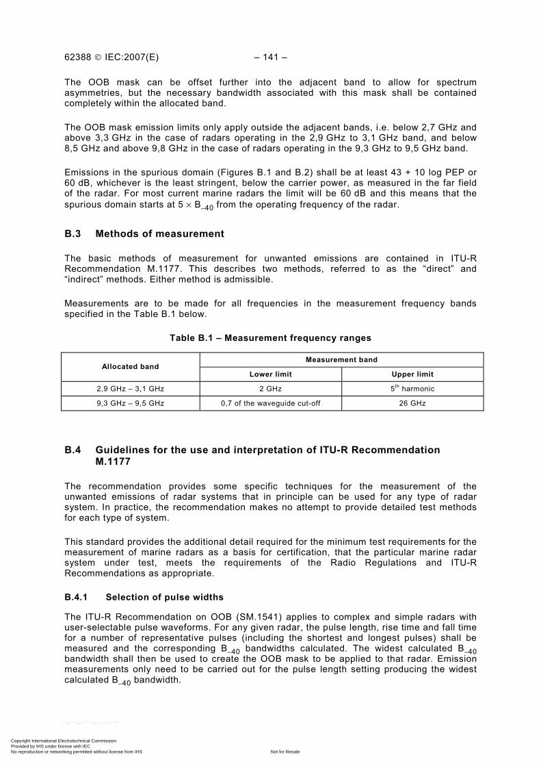
62388 © IEC:2007(E) – 141 –
The OOB mask can be offset further into the adjacent band to allow for spectrum asymmetries, but the necessary bandwidth associated with this mask shall be contained completely within the allocated band.
The OOB mask emission limits only apply outside the adjacent bands, i.e. below 2,7 GHz and above 3,3 GHz in the case of radars operating in the 2,9 GHz to 3,1 GHz band, and below 8,5 GHz and above 9,8 GHz in the case of radars operating in the 9,3 GHz to 9,5 GHz band.
Emissions in the spurious domain (Figures B.1 and B.2) shall be at least 43 + 10 log PEP or 60 dB, whichever is the least stringent, below the carrier power, as measured in the far field of the radar. For most current marine radars the limit will be 60 dB and this means that the spurious domain starts at 5 × B–40 from the operating frequency of the radar.
B.3 Methods of measurement
The basic methods of measurement for unwanted emissions are contained in ITU-R Recommendation M.1177. This describes two methods, referred to as the “direct” and “indirect” methods. Either method is admissible.
Measurements are to be made for all frequencies in the measurement frequency bands specified in the Table B.1 below.
Table B.1 – Measurement frequency ranges
Measurement band Allocated band
Lower limit Upper limit
2,9 GHz – 3,1 GHz 2 GHz 5th harmonic
9,3 GHz – 9,5 GHz 0,7 of the waveguide cut-off 26 GHz
B.4 Guidelines for the use and interpretation of ITU-R Recommendation M.1177
The recommendation provides some specific techniques for the measurement of the unwanted emissions of radar systems that in principle can be used for any type of radar system. In practice, the recommendation makes no attempt to provide detailed test methods for each type of system.
This standard provides the additional detail required for the minimum test requirements for the measurement of marine radars as a basis for certification, that the particular marine radar system under test, meets the requirements of the Radio Regulations and ITU-R Recommendations as appropriate.
B.4.1 Selection of pulse widths
The ITU-R Recommendation on OOB (SM.1541) applies to complex and simple radars with user-selectable pulse waveforms. For any given radar, the pulse length, rise time and fall time for a number of representative pulses (including the shortest and longest pulses) shall be measured and the corresponding B–40 bandwidths calculated. The widest calculated B–40 bandwidth shall then be used to create the OOB mask to be applied to that radar. Emission measurements only need to be carried out for the pulse length setting producing the widest calculated B–40 bandwidth.
Copyright International Electrotechnical Commission Provided by IHS under license with IEC
Not for ResaleNo reproduction or networking permitted without license from IHS
--`,,```,,,,````-`-`,,`,,`,`,,`---
– 142 – 62388 © IEC:2007(E)
B.4.2 Measurement in azimuth and elevation – antennas
For marine radars that are essentially surface search radars, there is no requirement to make measurements in the vertical plane.
For measurements in the azimuth plane, the antenna may be either rotating or the measurement system may be aligned to the antenna bore sight and measurements in azimuth taken at appropriate antenna angles where the directions of unwanted emissions are known. Both techniques are admissible and the particular choice shall be made by agreement between the manufacturer and the test authority. In both cases, the maximum value of the emission occurring in the azimuth plane shall be recorded over the frequency range defined in Table B.1.
Provided that all of the antennas to be used with the equipment under test are of the same type in general structure for the design and construction of the radiation mechanism, then only the smallest antenna with the worst case unwanted emission profile needs to be tested to verify compliance with the unwanted emission requirements.
B.5 Required results
B.5.1 Necessary bandwidth
The necessary bandwidth as calculated from the measured pulse width, rise time and fall time shall be within the allocated frequency band.
B.5.2 B–40 bandwidth
The B–40 bandwidth shall be calculated using the methods defined in B.4.1 and in Annex 8 of reference ITU-R Recommendation SM.1541. This bandwidth together with the declared frequency of the pulse transmission, are used to determine which of the masks illustrated in Figure B.1 or Figure B.2 shall be used for the purposes of conformity.
B.5.3 Emission spectrum
The emission spectrum shall be below the calculated mask, as determined by B.5.2 above, in both the OOB and spurious domains, for all appropriate frequencies over the ranges specified in Table B.1. As previously indicated in Clause B.2, the OOB emission masks limits do not apply within the allocated band or the adjacent RD/ESS-bands. The spurious emission limit applies in the spurious domain, regardless of frequency band.
Systems shall be compliant if the OOB mask of Figure B.2 is offset further into the adjacent band to allow for spectrum asymmetries, provided that the necessary bandwidth associated with this mask is completely contained within the allocated band.
NOTE 1 References:
a) ITU-R Recommendation M.1177: Techniques for measurement of unwanted emissions for radar systems.
b) ITU-R Recommendation M.1313: Technical characteristics of maritime radio-navigation radars.
c) ITU-R Recommendation SM.329: Spurious emissions.
d) ITU-R Recommendation SM.1541: Unwanted emissions in the out-of-band domain.
e) ITU-R Recommendation SM.1539: Variation of the boundary between the out-of-band and spurious domains required for the application of Recommendations ITU-R SM.1541 and ITU-R SM.329.
f) ITU-R Recommendation SM.1540: Unwanted emissions in the out-of-band domain falling into adjacent allocated bands.
g) ITU-R – Radio Regulations – Appendix 3: Spurious emissions.
NOTE 2 The latest version of the ITU-R Recommendation should be used.
Copyright International Electrotechnical Commission Provided by IHS under license with IEC
Not for ResaleNo reproduction or networking permitted without license from IHS
--`,,```,,,,````-`-`,,`,,`,`,,`---

62388 © IEC:2007(E) – 143 –
A
lloca
ted
Ban
d A
djac
ent R
D/E
ES
ban
d A
djac
ent R
D/E
ES
ban
d
Spu
rious
do
mai
n O
OB
dom
ain
Spu
rious
do
mai
n O
OB
dom
ain
–40
dB
20 d
B/d
ecad
e 20
dB
/dec
ade
2,7
GH
z 8,
5 G
Hz
2,9
GH
z 9,
3 G
Hz
3,1
GH
z 9,
5 G
Hz
3,3
GH
z 9,
8 G
Hz
Spu
rious
em
issi
on
limit
–60
dB o
r
–(43
+ 1
0 lo
g 10
PE
P)
B–4
0 dB
IEC
15
38/0
2
NO
TE 1
RD
/EE
S –
Rad
io-d
eter
min
atio
n/E
arth
Exp
lora
tion
Sat
ellit
e.
NO
TE 2
OO
B e
mis
sion
mas
k lim
its d
o no
t app
ly w
ithin
the
allo
cate
d or
adj
acen
t RD
/EE
S b
ands
.
Figu
re B
.1 –
B–4
0 fa
lls w
ithin
the
allo
cate
d ba
nd
Copyright International Electrotechnical Commission Provided by IHS under license with IEC
Not for ResaleNo reproduction or networking permitted without license from IHS
--`,,```,,,,````-`-`,,`,,`,`,,`---

– 144 – 62388 © IEC:2007(E)
Allo
cate
d ba
nd
Adj
acen
t RD
/EES
ban
d A
djac
ent R
D/E
ES
ban
d
Spu
rious
do
mai
n O
OB
do
mai
n S
purio
us
dom
ain
OO
B
dom
ain
–40
dB
20 d
B/d
ecad
e20
dB
/dec
ade
0 dB
2,7
GH
z 8,
5 G
Hz
2,9
GH
z 9,
3 G
Hz
3,1
GH
z 9,
5 G
Hz
3,3
GH
z 9,
8 G
Hz
Spu
rious
em
issi
on
limit
B–4
0 dB
–60
dB o
r
–(43
+ 1
0 lo
g 10
PE
P)
IEC
15
39/0
2
NO
TE 1
RD
/EE
S –
Rad
io-d
eter
min
atio
n/E
arth
Exp
lora
tion
Sat
ellit
e.
NO
TE 2
OO
B e
mis
sion
mas
k lim
its d
o no
t app
ly w
ithin
the
allo
cate
d or
adj
acen
t RD
/EE
S b
ands
.
Figu
re B
.2 –
B–4
0 fa
lls o
utsi
de th
e al
loca
ted
band
Copyright International Electrotechnical Commission Provided by IHS under license with IEC
Not for ResaleNo reproduction or networking permitted without license from IHS
--`,,```,,,,````-`-`,,`,,`,`,,`---

62388 © IEC:2007(E) – 145 –
Annex C (informative)
Radar target size (RCS) and detection range calculations
C.1 Radar range
Power density at range R from a radar antenna = G Pt/4π R2 W/m2
The maximum range of a radar target Rmax, is the distance beyond which the target cannot be detected. The received signal power Pr
(W) is:
Pr = Pt GAe
σ /(4 π)2 R4
When the received signal power Pr just equals the minimum detectable signal Smin, the radar
equation becomes:
Rmax = (Pt
GAe σ /(4π)2 Smin
)1/4
where
G is the antenna gain;
σ is the radar cross-section; Pt is the transmitted power;
Ae is the antenna effective aperture = G (wavelength)2/4π
C.2 Effect of a change of target size
Where a target of radar cross-section or "echoing area" s1 is substituted for s2 in the same circumstances, the corresponding change in power from p2 to p1 received back at the radar is given by
p1/p2 = s1/s2
hence 10 log (p1/p2) = 10 log (s1/s2) dB
Example 1
When a 30 m2 radar reflector is substituted for 10 m2, the change in power received back at the radar will be:
10 log (30/10) = 4,8 dB
C.3 Effect of a change of target range
Apart from other possible effects described in subsequent clauses, the relationship between power p1 reflected back from a target at distance d1, and power p2 reflected back from the same target at distance d2, is given by the inverse fourth power law as:
Copyright International Electrotechnical Commission Provided by IHS under license with IEC
Not for ResaleNo reproduction or networking permitted without license from IHS
--`,,```,,,,````-`-`,,`,,`,`,,`---
– 146 – 62388 © IEC:2007(E)
4
21
4
12
dp
dp=
In decibels, this equation becomes: 10 log (p2/p1) = –40 log (d2/d1) dB
Example 2
A change of distance from 2 NM to 3 NM will give, apart from other possible changes described below, a power change of:
–40 log (3/2) = –7,0 dB
C.4 Effect of target and radar height on discrete (non-distributed) targets
In calm to moderate sea states, a radar wave train that is reflected from the sea surface (with the angle of incidence equal to the angle of reflection) before striking the target will add vectorially with the wave train that travels directly to the target. This vectorial addition gives rise to a power enhancement Y seen at the radar. When Y is expressed in decibels it can vary between the limits +12 dB and – ∞ dB. This is of considerable importance when "discrete" or "point source" targets are used.
For the 3 cm band (9 410 MHz) and for the 10 cm band (3 050 MHz), values for the enhancement Y (in decibels) can be read from Figures C.1 and C.2. The formulae on which the values in Figures C.1 and C.2 are based are given in Clause C.7.
Example 3
Question: Referring to an X-band radar whose antenna height above the sea is 15 m, at what height above the sea must a physically small 10 m2 target be mounted, at a distance of 2 NM, in order to give a net effect of 10 m2 at this distance?
Answer: This will be the condition where enhancement Y = 0 dB.
By inspection of the curve for 9 410 MHz in Figure C.1, the minimum such height is 0,7 m.
C.5 Effects of frequency sensitivity
Certain types of target are frequency sensitive, as will be indicated in the formula relating the physical dimensions of the particular device to its radar cross-section. For a trihedral corner reflector the radar cross-section varies as the square of frequency. For example the performance of a trihedral corner reflector will be reduced by 9,9 dB at S-band compared with X-band. It must be borne in mind also that a change of operating frequency will affect in addition the considerations described in Clause C.4 above.
C.6 Conclusion
Factors that affect the performance of given radar targets under normal propagation conditions are described above. This gives a theoretical method whereby one target may be compared with another, by simple addition of the various factors expressed in decibels.
Example 4
Question: It is calculated from the dimensions of a particular corner reflector that its radar cross-section (echoing area) is 30 m2 (in free space) at a frequency of 9 410 MHz (X-band). This reflector is mounted at a height of 2,5 m above sea level,
Copyright International Electrotechnical Commission Provided by IHS under license with IEC
Not for ResaleNo reproduction or networking permitted without license from IHS
--`,,```,,,,````-`-`,,`,,`,`,,`---
62388 © IEC:2007(E) – 147 –
at a distance of 3 NM from a radar antenna mounted at a height of 15 m and operating at X-band.
How might the power returned to the radar from this reflector be expected to compare with that from a 10 m2 target situated at 2 NM from the radar at a height of 0,7 m (as used in example 3)?
Answer: Considering the various relevant factors:
a) power change due to greater target size is 10 log (30/10) = +4,8 dB b) power change due to greater distance is –40 log (3/2) = –7,0 dB c) power change (enhancement) due to lobing at 3 NM
is seen by inspection of Figure C.1 (9 410 MHz, target height 2,5 m) is = +10,7 dB
Adding the above three factors, the following answer is obtained +8,5 dB
C.7 Formulae for Figures C.1 and C.2
Y = 16 sin4 Dc
fhh 2
4 21π
where h1 is the radar height above the tangent plane to the h2 is the target height earth at the reflection point; f is the frequency of operation; c is the velocity of microwave propagation;
D is the radar-to-target distance
NOTE For horizontal polarisation only:
In the case of the curved earth, the heights h1 and h2 above the tangent have to be determined from the corresponding heights hr and ht of the radar and target respectively above the surface, by use of the approximate relationships (obtained from geometrical considerations):
h1 = hr – 2
tr
2r
) (
) (
hhd
Dh
+
and
h2 = ht – 2
tr
2t
) (
) (
hhd
Dh
+
where d is the effective diameter of the "radio" earth (taken here as 6 371 × 4/3 × 2 = 16 990 km).
The formulae do not take the influence of "beam divergence" during reflection at the curved earth into account, which will reduce the maximum enhancement and "fill in" the nulls, thus increasing the minimum values of Y above – ∞.
⎫ ⎬ ⎭
Copyright International Electrotechnical Commission Provided by IHS under license with IEC
Not for ResaleNo reproduction or networking permitted without license from IHS
--`,,```,,,,````-`-`,,`,,`,`,,`---
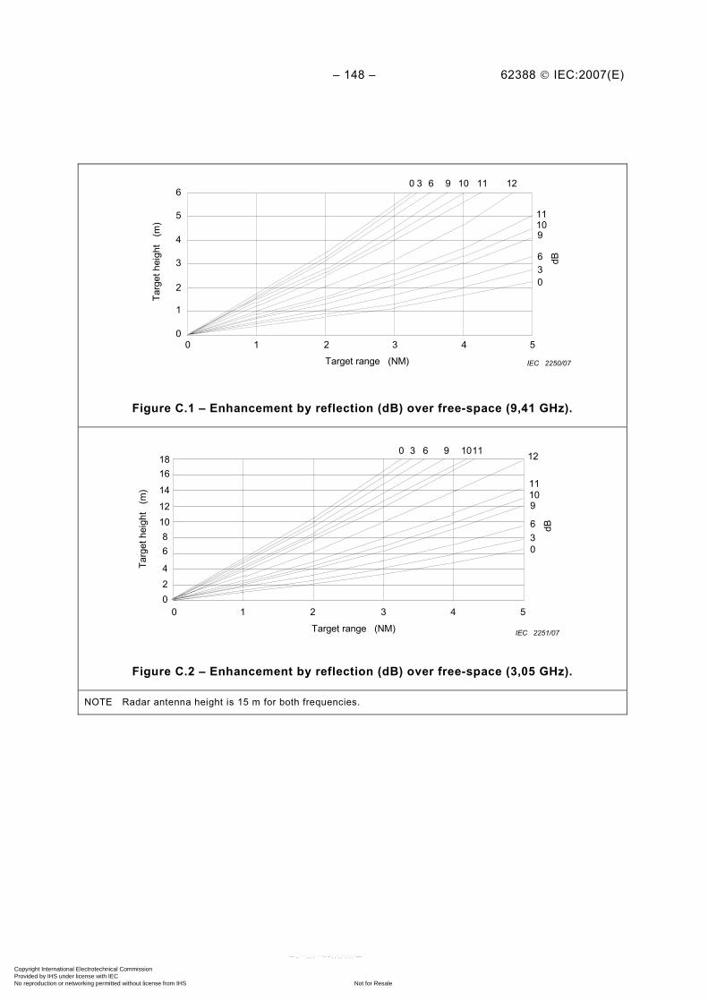
– 148 – 62388 © IEC:2007(E)
6
5
4
3
2
1
0
Targ
et h
eigh
t (m
)
0 1 2 3 4 5
0 3 6 9 10 11 12
11 10 9
6 3 0
dB
Target range (NM) IEC 2250/07
Figure C.1 – Enhancement by reflection (dB) over free-space (9,41 GHz).
18
Targ
et h
eigh
t (m
)
0 1 2 3 4 5
0 3 6 9 1011 12
11 10 9
6 3 0
dB
Target range (NM)
16
14
12 10 8 6
4 2 0
IEC 2251/07
Figure C.2 – Enhancement by reflection (dB) over free-space (3,05 GHz).
NOTE Radar antenna height is 15 m for both frequencies.
Copyright International Electrotechnical Commission Provided by IHS under license with IEC
Not for ResaleNo reproduction or networking permitted without license from IHS
--`,,```,,,,````-`-`,,`,,`,`,,`---

62388 © IEC:2007(E) – 149 –
Annex D (informative)
Factors that influence target detection
D.1 Detection
The detection of targets, particularly small or marginal radar targets, is very susceptible to target composition, antenna height and horizontal beam width, target size and height, sea state, clutter characteristics, and atmospheric conditions. Even small changes in these parameters will impact target detection and for targets at closer ranges (typically within 1,5 NM), signal amplitude may be affected by multi-path (see Figure D.2 and Figure D.3). Caution should therefore be exercised when performance comparisons are made with other radar equipment for assessment purposes; in this case it is essential that the two pieces of equipment are physically installed very close to each other and have the same antenna installation height.
D.2 Target RCS values
The relationship between X-band and S-band RCS values for small point targets is assumed to be in the ratio of 10:1. Some targets may produce a smaller ratio or an even larger RCS value for S-band, depending on the target characteristics. Guidelines for calculations based on simplified formula relating to different target properties and detection ranges are located in Annex C. Simple, stable and established point targets will provide a more consistent reference than a distributed target. An example of a distributed target is a large yacht, comprising multiple reflective surfaces, each of differing radar cross-section and at various heights, and having multiple polarisation reflections.
The RCS of a shoreline is variable according to the reflectivity of the surface. As the range of a shoreline increases, the RCS may increase as a greater surface is illuminated by the antenna beam. The surface illuminated is partly offset by the curvature of the earth and increased scattering of reflected signals. Shoreline radar visibility should therefore rely on the experience of a test authority and the performance assessment related to their expectations within a known environment.
The RCS of a large SOLAS ship will vary primarily according to the structure, profile and aspect of the ship. Newer shipping, particularly HSC, will tend to have a much smoother profile and therefore have a correspondingly lower RCS. The aspect of the ship observed will also influence the RCS value.
Distributed targets generate a more complex multi-path and may produce different RCS values according to the antenna polarisation in use. A simple cylinder reflector such as a channel marker pole will provide a known RCS if the reflector is correctly installed to be stable and vertical. A small angular offset will greatly decrease the RCS values. For distributed targets including all ships, the target centroid height shall be assumed.
A Swerling 1 type target is chosen for the reference performance predictions. It is expected that if the targets are installed at sea then the effects of multi-path alone will cause significant signal variation. The Swerling 0 case may be applicable under calm very controlled conditions but in the case of floating targets the height and exact distance may vary, introducing differing multi-path effects. Further, as the sea roughens the multi-path signal is influenced by the roughness of the intervening ocean surface and specular reflection may no longer describe the indirect path.
Copyright International Electrotechnical Commission Provided by IHS under license with IEC
Not for ResaleNo reproduction or networking permitted without license from IHS
--`,,```,,,,````-`-`,,`,,`,`,,`---
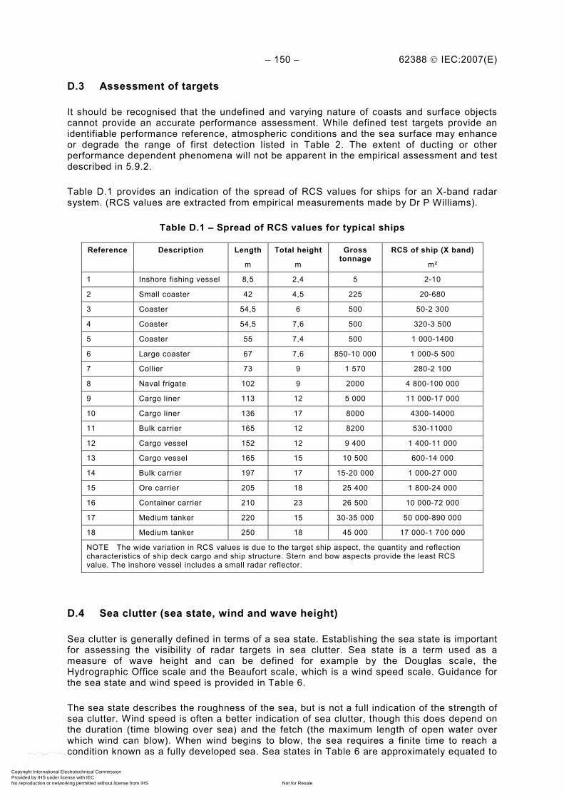
– 150 – 62388 © IEC:2007(E)
D.3 Assessment of targets
It should be recognised that the undefined and varying nature of coasts and surface objects cannot provide an accurate performance assessment. While defined test targets provide an identifiable performance reference, atmospheric conditions and the sea surface may enhance or degrade the range of first detection listed in Table 2. The extent of ducting or other performance dependent phenomena will not be apparent in the empirical assessment and test described in 5.9.2.
Table D.1 provides an indication of the spread of RCS values for ships for an X-band radar system. (RCS values are extracted from empirical measurements made by Dr P Williams).
Table D.1 – Spread of RCS values for typical ships
Reference Description Length
m
Total height
m
Gross tonnage
RCS of ship (X band)
m²
1 Inshore fishing vessel 8,5 2,4 5 2-10
2 Small coaster 42 4,5 225 20-680
3 Coaster 54,5 6 500 50-2 300
4 Coaster 54,5 7,6 500 320-3 500
5 Coaster 55 7,4 500 1 000-1400
6 Large coaster 67 7,6 850-10 000 1 000-5 500
7 Collier 73 9 1 570 280-2 100
8 Naval frigate 102 9 2000 4 800-100 000
9 Cargo liner 113 12 5 000 11 000-17 000
10 Cargo liner 136 17 8000 4300-14000
11 Bulk carrier 165 12 8200 530-11000
12 Cargo vessel 152 12 9 400 1 400-11 000
13 Cargo vessel 165 15 10 500 600-14 000
14 Bulk carrier 197 17 15-20 000 1 000-27 000
15 Ore carrier 205 18 25 400 1 800-24 000
16 Container carrier 210 23 26 500 10 000-72 000
17 Medium tanker 220 15 30-35 000 50 000-890 000
18 Medium tanker 250 18 45 000 17 000-1 700 000
NOTE The wide variation in RCS values is due to the target ship aspect, the quantity and reflection characteristics of ship deck cargo and ship structure. Stern and bow aspects provide the least RCS value. The inshore vessel includes a small radar reflector.
D.4 Sea clutter (sea state, wind and wave height)
Sea clutter is generally defined in terms of a sea state. Establishing the sea state is important for assessing the visibility of radar targets in sea clutter. Sea state is a term used as a measure of wave height and can be defined for example by the Douglas scale, the Hydrographic Office scale and the Beaufort scale, which is a wind speed scale. Guidance for the sea state and wind speed is provided in Table 6.
The sea state describes the roughness of the sea, but is not a full indication of the strength of sea clutter. Wind speed is often a better indication of sea clutter, though this does depend on the duration (time blowing over sea) and the fetch (the maximum length of open water over which wind can blow). When wind begins to blow, the sea requires a finite time to reach a condition known as a fully developed sea. Sea states in Table 6 are approximately equated to
Copyright International Electrotechnical Commission Provided by IHS under license with IEC
Not for ResaleNo reproduction or networking permitted without license from IHS
--`,,```,,,,````-`-`,,`,,`,`,,`---

62388 © IEC:2007(E) – 151 –
wind speeds. During any assessment or measurement, it shall be noted that sea swell will make accurate assessment of wave observations very difficult and the table is only applicable to waves formed by local wind conditions.
Crosswinds relative to the line of sight to the target produce less clutter than head winds and in terms of clutter returns, this represents 2 dB to 3 dB (approximately half a numerical sea state) less clutter signal return than detecting a target in head wind.
Many variables impact on actual radar performance and a controlled test cannot fully cover all of these, nor can conditions during type approval be rigidly specified. For example, in the Sea State 5 (SS 5) situation, a 5 m² RCS target may demonstrate low probability of detection in the near range with an acceptable or high probability of detection in the further ranges.
Figure D.1 illustrates this case for a probability of detection with a low false alarm rate. Sea clutter may vary so that lower detection is achieved due to the presence of wave spikes. Atmospheric conditions can enhance or degrade detection performance. The presence of rain will further degrade performance in the local area of the rain by causing additional clutter and target return loss.
Detection of a Navigation Buoy in Spiky Clutter Sea State 5, Short Pulse, X-band
0 10 20 30 40 50 60 70 80 90
100
0 1 2 3 4 5 6 Range (NM)
Pd
(%
)
v = 30 v = 10 v = 1 v = calc no clutter
IEC 2252/07
Figure D.1 – Effect of sea spikes on target detection
NOTE Factor “v” is the sea spike factor which depends on the sea conditions in the locality. The lower v gives a more spiky clutter. High sea spikes will require a user to increase the detection threshold, thereby degrading detection performance. The performance will also be adversely influenced by target obscuration (screening). Plot v = calc is the value used for the predictions.
In assessing the suitability of particular radar to the task at hand it is important to be able to model detection performance. This process must include the computation of the expected received signals from targets and clutter, and the system noise level. One of the more difficult problems in predicting radar target detection over the sea is accurately accounting for the effect of sea clutter. A number of models are available to provide the average normalised radar cross-section for the ocean as a function of sea state. The sea clutter statistical properties play a significant role in detection as a radar must operate with a relatively low false alarm rate, meaning the tail of the sea clutter distribution will have a major effect on the detection threshold. Models for the statistical properties of sea clutter vary from the Rayleigh
Copyright International Electrotechnical Commission Provided by IHS under license with IEC
Not for ResaleNo reproduction or networking permitted without license from IHS
--`,,```,,,,````-`-`,,`,,`,`,,`---

– 152 – 62388 © IEC:2007(E)
distribution for low resolution radars and high grazing angles, to Weibull and Log-normal for high resolution radars or low grazing angles. The K-distribution has been proposed in numerous papers and it offers a number of benefits for modelling the physical properties of sea clutter. The K-distribution shape parameter, ‘v’, controls the tail of the distribution and for a small shape parameter the sea clutter becomes very spiky and for a large shape parameter the distribution provides Rayleigh clutter.
Tables D.2 and D.3 present performance predictions for target detection in sea clutter by an S-band and an X-band radar respectively (with parameters as defined in Clause D.7), using the K-distribution sea clutter model. Entries with an asterisk are not computed as they are not needed to determine detectability. The predictions are generally more pessimistic than those provided using the CARPET tool. These differences are due primarily to the introduction of the K-distribution for the sea clutter. Comparative calculations using a large K-distribution shape parameter provide similar predictions to CARPET.
It should be noted that in operational conditions, the conditions selected for the modelled environment would never be achieved exactly. As a result the performance predictions are only indicative of the performance achieved in the real world and hence are only provided for guidance. Probability-of-detection (Pd) figures are expressed as a percentage and a probability of false alarm (Pfa) of 10–4 is assumed.
Table D.2 – S-band performance predictions (Pfa = 10–4) for ranges of 0,2, 0,4, 0,7 NM
Table D.3 – X-band performance predictions (Pfa = 10–4) for ranges of 0,2, 0,7 NM
X-band Pd (%) RCS
(m2) Sea state 1 Sea state 2 Sea state 3 Sea state 4 Sea state 5 Sea state 6
0,2 0,7 0,2 0,7 0,2 0,7 0,2 0,7 0,2 0,7 0,2 0,7
1 100 100 85 98 53 60 30 10 23 3 11 0
5 >98 >91 >96 >98 90 91 83 63 75 45 63 30
10 >98 >91 >93 >92 >94 >93 91 76 85 65 75 52
The predictions provided in Table D.2 and Table D.3 are made without any signal processing that may be available in the radar system. In fixed frequency radar, little benefit is gained from pulse to pulse processing in sea clutter limited detection due to the correlation time for the clutter. Scan to scan processing has the potential for reducing the effect of clutter spikes provided the scan processing can operate over a period of time that permits the clutter spikes to de-correlate.
D.5 Signal multi-path
Target detection, particularly in calm conditions and in lower sea states conditions, is greatly influenced by multi-path, a phenomenon created by multiple signal paths from a given target. Multi-path is influential at closer ranges and depends on many variables, including the
S-band Pd (%) RCS
(m2) Sea state 1 Sea state 2 Sea state 3 Sea state 4 Sea state 5 Sea state 6
0,2 0,4 0,7 0,2 0,4 0,7 0,2 0,4 0,7 0,2 0,4 0,7 0,2 0,4 0,7 0,2 0,4 0,7
0,1 100 100 100 95 100 100 59 83 95 14 34 50 5 4 7 * * *
0,5 * * * 99 100 100 91 97 99 65 75 87 52 47 57 45 30 26
1 * * * 100 100 100 93 98 99 84 90 95 76 65 77 66 60 52
Copyright International Electrotechnical Commission Provided by IHS under license with IEC
Not for ResaleNo reproduction or networking permitted without license from IHS
--`,,```,,,,````-`-`,,`,,`,`,,`---
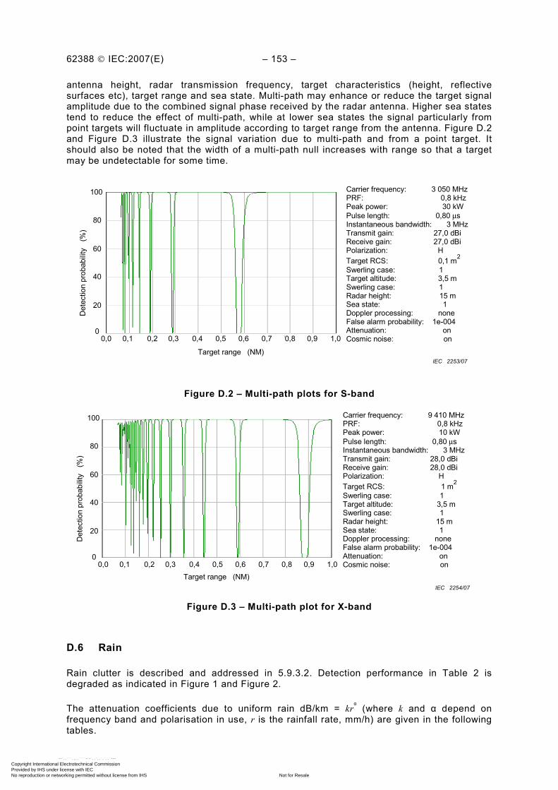
62388 © IEC:2007(E) – 153 –
antenna height, radar transmission frequency, target characteristics (height, reflective surfaces etc), target range and sea state. Multi-path may enhance or reduce the target signal amplitude due to the combined signal phase received by the radar antenna. Higher sea states tend to reduce the effect of multi-path, while at lower sea states the signal particularly from point targets will fluctuate in amplitude according to target range from the antenna. Figure D.2 and Figure D.3 illustrate the signal variation due to multi-path and from a point target. It should also be noted that the width of a multi-path null increases with range so that a target may be undetectable for some time.
100
80
60
40
20
0 0,0 0,1 0,2 0,3 0,7 0,8 0,9 1,0
Target range (NM)
0,4 0,5 0,6
Carrier frequency: 3 050 MHz PRF: 0,8 kHz Peak power: 30 kW Pulse length: 0,80 μs Instantaneous bandwidth: 3 MHz Transmit gain: 27,0 dBi Receive gain: 27,0 dBi Polarization: H Target RCS: 0,1 m2 Swerling case: 1 Target altitude: 3,5 m Swerling case: 1 Radar height: 15 m Sea state: 1 Doppler processing: none False alarm probability: 1e-004 Attenuation: on Cosmic noise: on
Det
ectio
n pr
obab
ility
(%
)
IEC 2253/07
Figure D.2 – Multi-path plots for S-band
100
80
60
40
20
Carrier frequency: 9 410 MHz PRF: 0,8 kHz Peak power: 10 kW Pulse length: 0,80 μs Instantaneous bandwidth: 3 MHz Transmit gain: 28,0 dBi Receive gain: 28,0 dBi Polarization: H Target RCS: 1 m2 Swerling case: 1 Target altitude: 3,5 m Swerling case: 1 Radar height: 15 m Sea state: 1 Doppler processing: none False alarm probability: 1e-004 Attenuation: on Cosmic noise: on
Det
ectio
n pr
obab
ility
(%
)
0 0,0 0,1 0,2 0,3 0,7 0,8 0,9 1,00,4 0,5 0,6
Target range (NM) IEC 2254/07
Figure D.3 – Multi-path plot for X-band
D.6 Rain
Rain clutter is described and addressed in 5.9.3.2. Detection performance in Table 2 is degraded as indicated in Figure 1 and Figure 2.
The attenuation coefficients due to uniform rain dB/km = krα (where k and α depend on
frequency band and polarisation in use, r is the rainfall rate, mm/h) are given in the following tables.
Copyright International Electrotechnical Commission Provided by IHS under license with IEC
Not for ResaleNo reproduction or networking permitted without license from IHS
--`,,```,,,,````-`-`,,`,,`,`,,`---
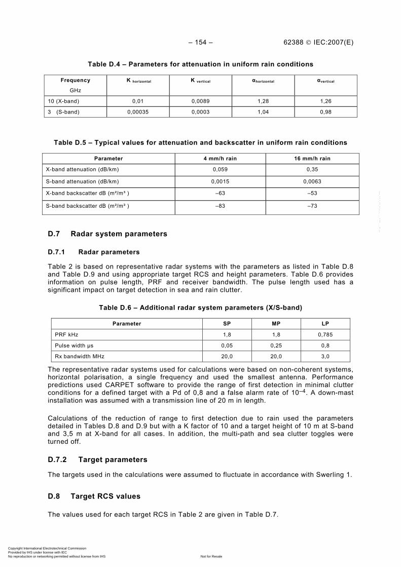
– 154 – 62388 © IEC:2007(E)
Table D.4 – Parameters for attenuation in uniform rain conditions
Frequency
GHz
K horizontal K vertical αhorizontal αvertical
10 (X-band) 0,01 0,0089 1,28 1,26
3 (S-band) 0,00035 0,0003 1,04 0,98
Table D.5 – Typical values for attenuation and backscatter in uniform rain conditions
Parameter 4 mm/h rain 16 mm/h rain
X-band attenuation (dB/km) 0,059 0,35
S-band attenuation (dB/km) 0,0015 0,0063
X-band backscatter dB (m²/m³ ) –63 –53
S-band backscatter dB (m²/m³ ) –83 –73
D.7 Radar system parameters
D.7.1 Radar parameters
Table 2 is based on representative radar systems with the parameters as listed in Table D.8 and Table D.9 and using appropriate target RCS and height parameters. Table D.6 provides information on pulse length, PRF and receiver bandwidth. The pulse length used has a significant impact on target detection in sea and rain clutter.
Table D.6 – Additional radar system parameters (X/S-band)
Parameter SP MP LP
PRF kHz 1,8 1,8 0,785
Pulse width µs 0,05 0,25 0,8
Rx bandwidth MHz 20,0 20,0 3,0
The representative radar systems used for calculations were based on non-coherent systems, horizontal polarisation, a single frequency and used the smallest antenna. Performance predictions used CARPET software to provide the range of first detection in minimal clutter conditions for a defined target with a Pd of 0,8 and a false alarm rate of 10–4. A down-mast installation was assumed with a transmission line of 20 m in length.
Calculations of the reduction of range to first detection due to rain used the parameters detailed in Tables D.8 and D.9 but with a K factor of 10 and a target height of 10 m at S-band and 3,5 m at X-band for all cases. In addition, the multi-path and sea clutter toggles were turned off.
D.7.2 Target parameters
The targets used in the calculations were assumed to fluctuate in accordance with Swerling 1.
D.8 Target RCS values
The values used for each target RCS in Table 2 are given in Table D.7.
Copyright International Electrotechnical Commission Provided by IHS under license with IEC
Not for ResaleNo reproduction or networking permitted without license from IHS
--`,,```,,,,````-`-`,,`,,`,`,,`---
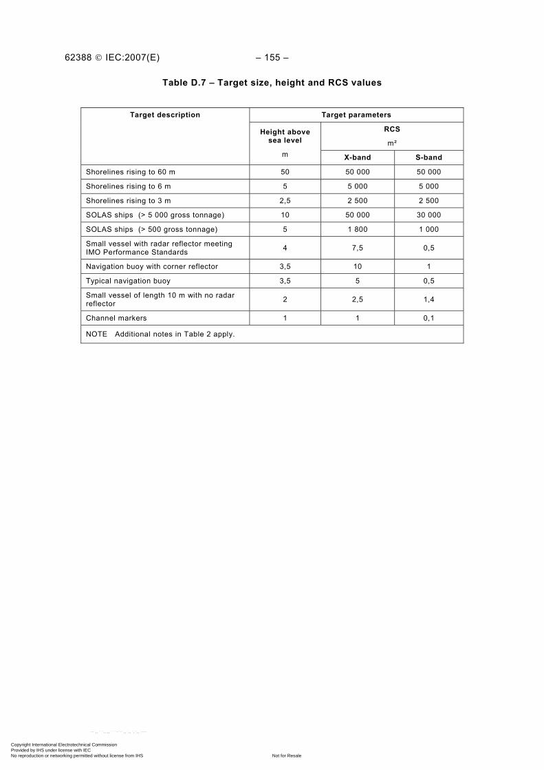
62388 © IEC:2007(E) – 155 –
Table D.7 – Target size, height and RCS values
Target parameters
RCS
m²
Target description
Height above sea level
m X-band S-band
Shorelines rising to 60 m 50 50 000 50 000
Shorelines rising to 6 m 5 5 000 5 000
Shorelines rising to 3 m 2,5 2 500 2 500
SOLAS ships (> 5 000 gross tonnage) 10 50 000 30 000
SOLAS ships (> 500 gross tonnage) 5 1 800 1 000
Small vessel with radar reflector meeting IMO Performance Standards
4 7,5 0,5
Navigation buoy with corner reflector 3,5 10 1
Typical navigation buoy 3,5 5 0,5
Small vessel of length 10 m with no radar reflector 2 2,5 1,4
Channel markers 1 1 0,1
NOTE Additional notes in Table 2 apply.
Copyright International Electrotechnical Commission Provided by IHS under license with IEC
Not for ResaleNo reproduction or networking permitted without license from IHS
--`,,```,,,,````-`-`,,`,,`,`,,`---
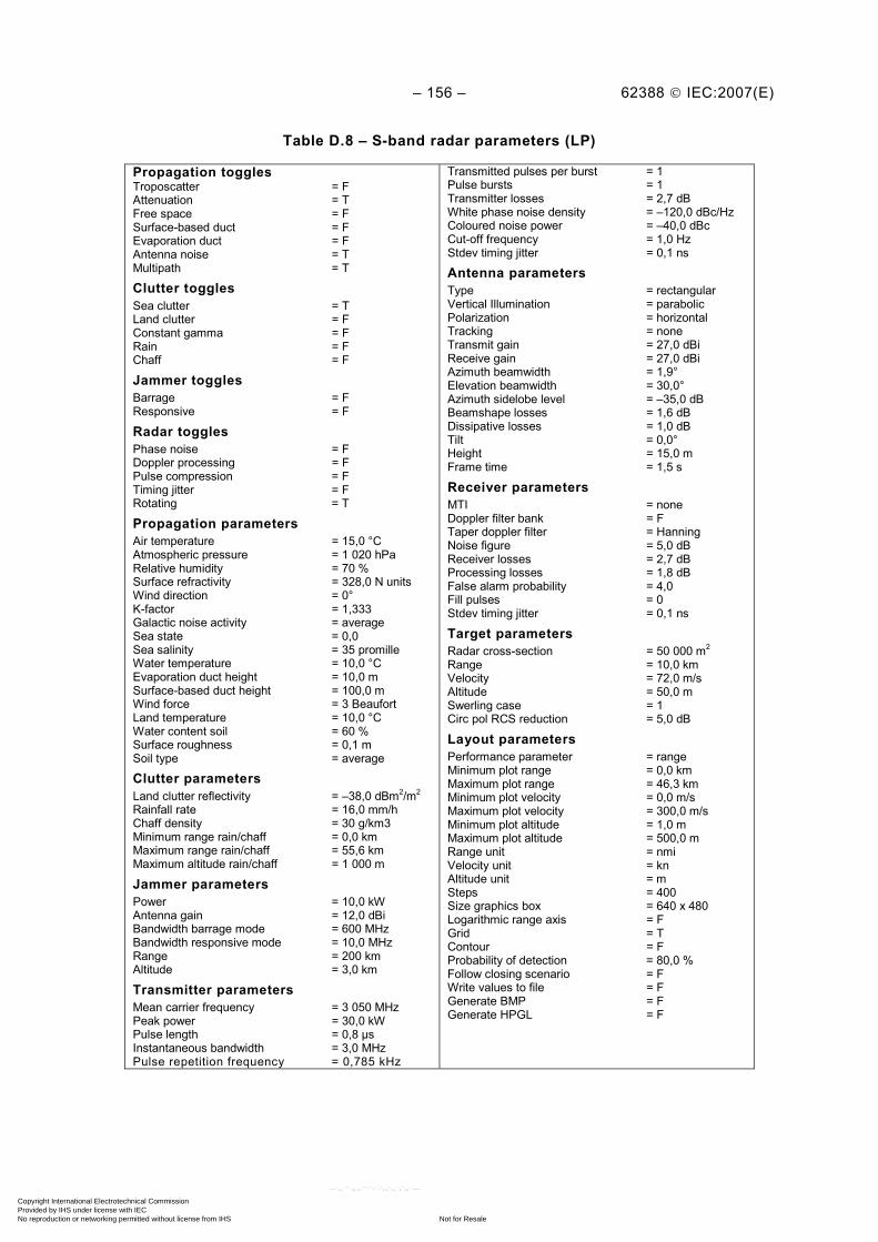
– 156 – 62388 © IEC:2007(E)
Table D.8 – S-band radar parameters (LP)
Propagation toggles Troposcatter = F Attenuation = T Free space = F Surface-based duct = F Evaporation duct = F Antenna noise = T Multipath = T
Clutter toggles Sea clutter = T Land clutter = F Constant gamma = F Rain = F Chaff = F
Jammer toggles Barrage = F Responsive = F
Radar toggles Phase noise = F Doppler processing = F Pulse compression = F Timing jitter = F Rotating = T
Propagation parameters Air temperature = 15,0 °C Atmospheric pressure = 1 020 hPa Relative humidity = 70 % Surface refractivity = 328,0 N units Wind direction = 0° K-factor = 1,333 Galactic noise activity = average Sea state = 0,0 Sea salinity = 35 promille Water temperature = 10,0 °C Evaporation duct height = 10,0 m Surface-based duct height = 100,0 m Wind force = 3 Beaufort Land temperature = 10,0 °C Water content soil = 60 % Surface roughness = 0,1 m Soil type = average
Clutter parameters Land clutter reflectivity = –38,0 dBm2/m2 Rainfall rate = 16,0 mm/h Chaff density = 30 g/km3 Minimum range rain/chaff = 0,0 km Maximum range rain/chaff = 55,6 km Maximum altitude rain/chaff = 1 000 m
Jammer parameters Power = 10,0 kW Antenna gain = 12,0 dBi Bandwidth barrage mode = 600 MHz Bandwidth responsive mode = 10,0 MHz Range = 200 km Altitude = 3,0 km
Transmitter parameters Mean carrier frequency = 3 050 MHz Peak power = 30,0 kW Pulse length = 0,8 µs Instantaneous bandwidth = 3,0 MHz Pulse repetition frequency = 0,785 kHz
Transmitted pulses per burst = 1 Pulse bursts = 1 Transmitter losses = 2,7 dB White phase noise density = –120,0 dBc/Hz Coloured noise power = –40,0 dBc Cut-off frequency = 1,0 Hz Stdev timing jitter = 0,1 ns
Antenna parameters Type = rectangular Vertical Illumination = parabolic Polarization = horizontal Tracking = none Transmit gain = 27,0 dBi Receive gain = 27,0 dBi Azimuth beamwidth = 1,9° Elevation beamwidth = 30,0° Azimuth sidelobe level = –35,0 dB Beamshape losses = 1,6 dB Dissipative losses = 1,0 dB Tilt = 0,0° Height = 15,0 m Frame time = 1,5 s
Receiver parameters MTI = none Doppler filter bank = F Taper doppler filter = Hanning Noise figure = 5,0 dB Receiver losses = 2,7 dB Processing losses = 1,8 dB False alarm probability = 4,0 Fill pulses = 0 Stdev timing jitter = 0,1 ns
Target parameters Radar cross-section = 50 000 m2 Range = 10,0 km Velocity = 72,0 m/s Altitude = 50,0 m Swerling case = 1 Circ pol RCS reduction = 5,0 dB
Layout parameters Performance parameter = range Minimum plot range = 0,0 km Maximum plot range = 46,3 km Minimum plot velocity = 0,0 m/s Maximum plot velocity = 300,0 m/s Minimum plot altitude = 1,0 m Maximum plot altitude = 500,0 m Range unit = nmi Velocity unit = kn Altitude unit = m Steps = 400 Size graphics box = 640 x 480 Logarithmic range axis = F Grid = T Contour = F Probability of detection = 80,0 % Follow closing scenario = F Write values to file = F Generate BMP = F Generate HPGL = F
Copyright International Electrotechnical Commission Provided by IHS under license with IEC
Not for ResaleNo reproduction or networking permitted without license from IHS
--`,,```,,,,````-`-`,,`,,`,`,,`---

62388 © IEC:2007(E) – 157 –
Table D.9 – X-band radar parameters (LP)
Propagation toggles Troposcatter = F Attenuation = T Free space = F Surface-based duct = F Evaporation duct = F Antenna noise = T Multipath = T
Clutter toggles Sea clutter = T Land clutter = F Constant gamma = F Rain = F Chaff = F
Jammer toggles Barrage = F Responsive = F
Radar toggles Phase noise = F Doppler processing = F Pulse compression = F Timing jitter = F Rotating = T
Propagation parameters Air temperature = 15,0 °C Atmospheric pressure = 1 020 hPa Relative humidity = 70 % Surface refractivity = 328,0 Nunits Wind direction = 0° K-factor = 1,333 Galactic noise activity = average Sea state = 0,0 Sea salinity = 35 promille Water temperature = 10,0 °C Evaporation duct height = 10,0 m Surface-based duct height = 100,0 m Wind force = 3 Beaufort Land temperature = 10,0 °C Water content soil = 60 % Surface roughness = 0,1 m Soil type = average
Clutter parameters Land clutter reflectivity = –38,0 dBm2/m2 Rainfall rate = 16,0 mm/h Chaff density = 30 g/km3 Minimum range rain/chaff = 0,0 km Maximum range rain/chaff = 55,6 km Maximum altitude rain/chaff = 1 000 m
Jammer parameters Power = 10,0 kW Antenna gain = 12,0 dBi Bandwidth barrage mode = 600 MHz Bandwidth responsive mode = 10,0 MHz Range = 200 km Altitude = 3,0 km
Transmitter parameters Mean carrier frequency = 9 410 MHz Peak power = 10,0 kW Pulse length = 0,8 µs Instantaneous bandwidth = 3,0 MHz Pulse repetition frequency = 0,785 kHz
Transmitted pulses per burst = 1 Pulse bursts = 1 Transmitter losses = 2,7 dB White phase noise density = –120,0 dBc/Hz Coloured noise power = –40,0 dBc Cut-off frequency = 1,0 Hz StDev timing jitter = 0,100 ns
Antenna parameters Type = rectangular Vertical illumination = parabolic Polarization = horizontal Tracking = none Transmit gain = 28,0 dBi Receive gain = 28,0 dBi Azimuth beamwidth = 1,8° Elevation beamwidth = 24,0° Azimuth sidelobe level = –25,0 dB Beamshape losses = 1,6 dB Dissipative losses = 1,0 dB Tilt = 0,0° Height = 15,0 m Frame time = 1,5 s
Receiver parameters MTI = none Doppler filter bank = F Taper doppler filter = Hanning Noise figure = 5,0 dB Receiver losses = 2,7 dB Processing losses = 1,8 dB False alarm probability = 4,0 Fill pulses = 0 StDev timing jitter = 0,1 ns
Target parameters Radar cross-section = 50 000 m2 Range = 10,0 km Velocity = 72,0 m/s Altitude = 50,0 m Swerling case = 1 Circ pol RCS reduction = 5,0 dB
Layout parameters Performance parameter = range Minimum plot range = 0,0 km Maximum plot range = 46,3 km Minimum plot velocity = 0,0 m/s Maximum plot velocity = 300,0 m/s Minimum plot altitude = 1,0 m Maximum plot altitude = 500,0 m Range unit = nmi Velocity unit = kn Altitude unit = m Steps = 400 Size graphics box = 640 x 480 Logarithmic range axis = F Grid = T Contour = F Probability of detection = 80,0 % Follow closing scenario = F Write values to file = F Generate BMP = F Generate HPGL = F
Copyright International Electrotechnical Commission Provided by IHS under license with IEC
Not for ResaleNo reproduction or networking permitted without license from IHS
--`,,```,,,,````-`-`,,`,,`,`,,`---

– 158 – 62388 © IEC:2007(E)
Annex E (normative)
Sensor errors
The accuracy figures quoted in 10.3.14 are based upon the following sensor errors and are appropriate to equipment complying with the performance standards for shipborne navigational equipment.
E.1 Radar
E.1.1 Target glint (scintillation) (for 200 m length target)
Along length of target σ = 30 m (normal distribution)
NOTE σ means "standard deviation”.
Across beam of target σ = 1 m (normal distribution)
E.1.2 Roll-pitch bearing
The bearing error will peak in each of the four quadrants around own ship for targets on relative bearings of 045°, 135°, 225° and 315° and will be zero at relative bearings of 0°, 90°, 180°, and 270°. This error has a sinusoidal variation at twice the roll frequency.
For a 10° roll, the mean error is 0,22° with a 0,22° peak sine wave superimposed.
E.1.3 Beam shape
Assumed normal distribution giving bearing error with σ = 0,05°
E.1.4 Pulse shape
Assumed normal distribution giving a 3 sigma range error of 2 m (1 σ = 0,66 m)
E.1.5 Antenna backlash
Assumed rectangular distribution giving bearing error ± 0,05° maximum
E.1.6 Quantization
Bearing – rectangular distribution ± 0,1° maximum
Range – rectangular distribution ± 0,01 NM maximum
Bearing encoder assumed to be running from a remote synchro giving bearing errors with a normal distribution σ = 0,03°.
E.2 Gyro-compass
Calibration error 0,0°. Normal distribution about this with σ = 0,08°
E.3 Log
Calibration error 0,0 kn. Normal distribution about this, 3 σ = 0,2 kn.
Copyright International Electrotechnical Commission Provided by IHS under license with IEC
Not for ResaleNo reproduction or networking permitted without license from IHS
--`,,```,,,,````-`-`,,`,,`,`,,`---

62388 © IEC:2007(E) – 159 –
E.4 Errors
The bearing error resulting from the combination of all sensor errors including target glint shall be limited to ± 0,6°. Calibration errors are regarded as having longer periods.
Copyright International Electrotechnical Commission Provided by IHS under license with IEC
Not for ResaleNo reproduction or networking permitted without license from IHS
--`,,```,,,,````-`-`,,`,,`,`,,`---
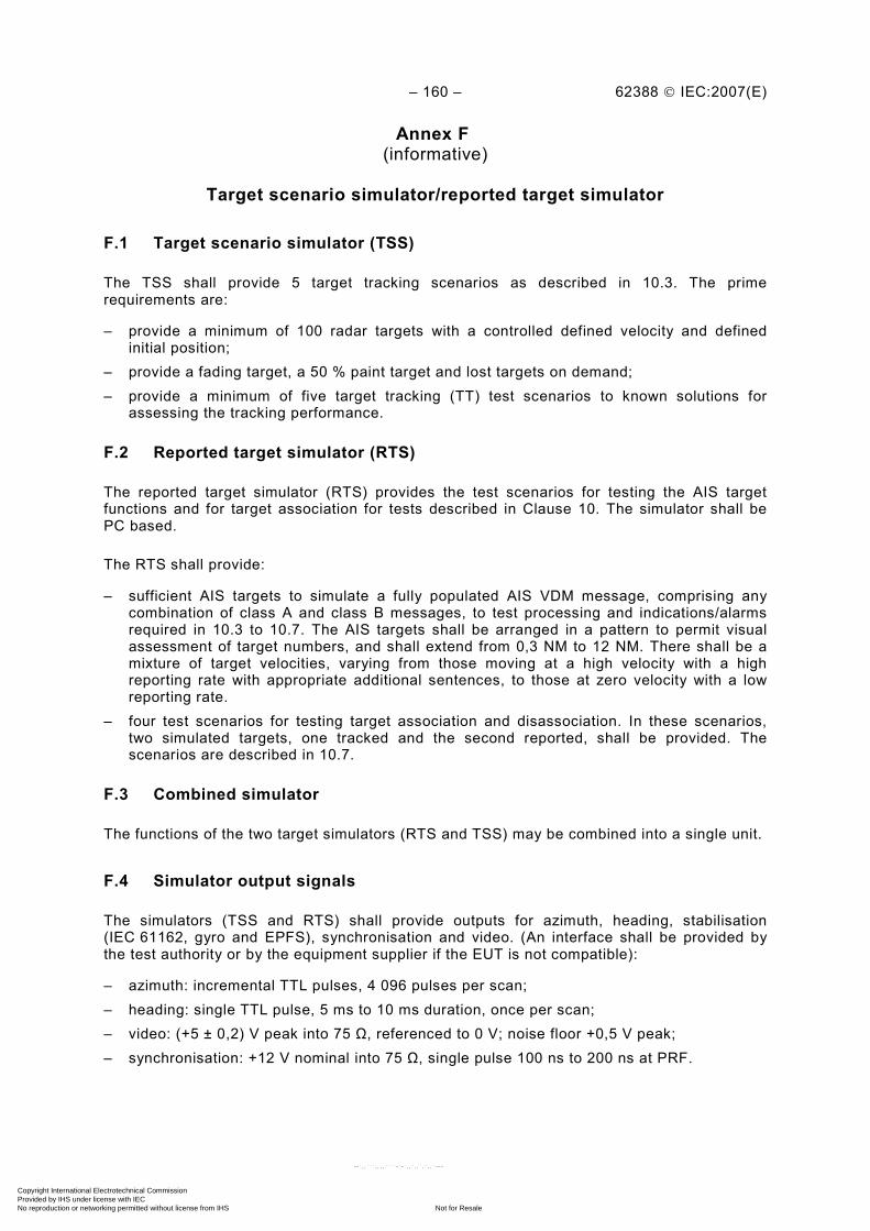
– 160 – 62388 © IEC:2007(E)
Annex F (informative)
Target scenario simulator/reported target simulator
F.1 Target scenario simulator (TSS)
The TSS shall provide 5 target tracking scenarios as described in 10.3. The prime requirements are:
– provide a minimum of 100 radar targets with a controlled defined velocity and defined initial position;
– provide a fading target, a 50 % paint target and lost targets on demand; – provide a minimum of five target tracking (TT) test scenarios to known solutions for
assessing the tracking performance.
F.2 Reported target simulator (RTS)
The reported target simulator (RTS) provides the test scenarios for testing the AIS target functions and for target association for tests described in Clause 10. The simulator shall be PC based.
The RTS shall provide:
– sufficient AIS targets to simulate a fully populated AIS VDM message, comprising any combination of class A and class B messages, to test processing and indications/alarms required in 10.3 to 10.7. The AIS targets shall be arranged in a pattern to permit visual assessment of target numbers, and shall extend from 0,3 NM to 12 NM. There shall be a mixture of target velocities, varying from those moving at a high velocity with a high reporting rate with appropriate additional sentences, to those at zero velocity with a low reporting rate.
– four test scenarios for testing target association and disassociation. In these scenarios, two simulated targets, one tracked and the second reported, shall be provided. The scenarios are described in 10.7.
F.3 Combined simulator
The functions of the two target simulators (RTS and TSS) may be combined into a single unit.
F.4 Simulator output signals
The simulators (TSS and RTS) shall provide outputs for azimuth, heading, stabilisation (IEC 61162, gyro and EPFS), synchronisation and video. (An interface shall be provided by the test authority or by the equipment supplier if the EUT is not compatible):
– azimuth: incremental TTL pulses, 4 096 pulses per scan; – heading: single TTL pulse, 5 ms to 10 ms duration, once per scan; – video: (+5 ± 0,2) V peak into 75 Ω, referenced to 0 V; noise floor +0,5 V peak; – synchronisation: +12 V nominal into 75 Ω, single pulse 100 ns to 200 ns at PRF.
Copyright International Electrotechnical Commission Provided by IHS under license with IEC
Not for ResaleNo reproduction or networking permitted without license from IHS
--`,,```,,,,````-`-`,,`,,`,`,,`---

62388 © IEC:2007(E) – 161 –
Annex G (informative)
Tracked and reported target states
Figure G.1 – Tracked target states
Figure G.2 – AIS target states
Established tracking
Manual acquisition
Non-tracking
No CPA/TCPA
alarm
Lost target
Delete target
Acquiringtarget
Acknowledge to silence alarm
Time-out will pass it further
Auto- acquisition
CPA/TCPA alarm CPA/TCPA +
acknowledged
IEC 2255/07
Established target
No target to report
Activatedtarget,
no alarm
Activated target,
CPA/TCPAalarm
Message received
Acknowledge to silence alarm
Time-out will pass it further
Lost target
Sleepingtarget,
no alarm
Activated target, CPA/TCPA + acknowledged
IEC 2256/07
Copyright International Electrotechnical Commission Provided by IHS under license with IEC
Not for ResaleNo reproduction or networking permitted without license from IHS
--`,,```,,,,````-`-`,,`,,`,`,,`---
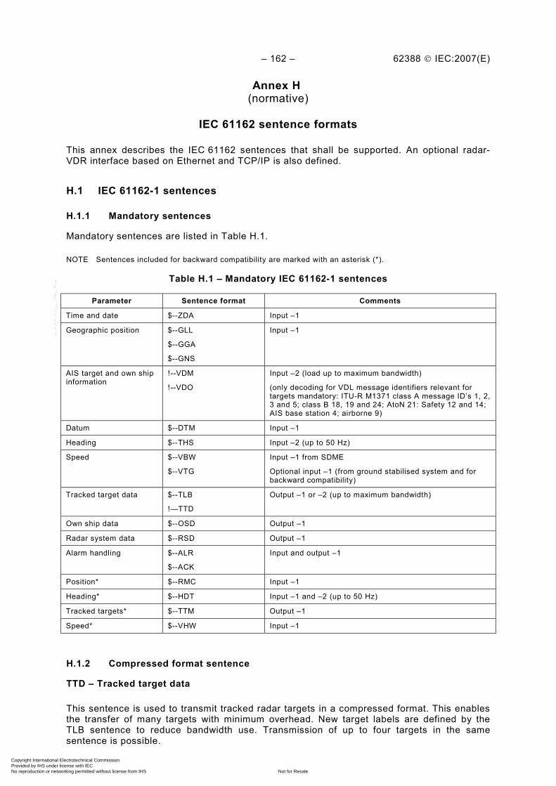
– 162 – 62388 © IEC:2007(E)
Annex H (normative)
IEC 61162 sentence formats
This annex describes the IEC 61162 sentences that shall be supported. An optional radar-VDR interface based on Ethernet and TCP/IP is also defined.
H.1 IEC 61162-1 sentences
H.1.1 Mandatory sentences
Mandatory sentences are listed in Table H.1.
NOTE Sentences included for backward compatibility are marked with an asterisk (*).
Table H.1 – Mandatory IEC 61162-1 sentences
Parameter Sentence format Comments
Time and date $--ZDA Input –1
Geographic position $--GLL
$--GGA
$--GNS
Input –1
AIS target and own ship information
!--VDM
!--VDO
Input –2 (load up to maximum bandwidth)
(only decoding for VDL message identifiers relevant for targets mandatory: ITU-R M1371 class A message ID’s 1, 2, 3 and 5; class B 18, 19 and 24; AtoN 21: Safety 12 and 14; AIS base station 4; airborne 9)
Datum $--DTM Input –1
Heading $--THS Input –2 (up to 50 Hz)
Speed $--VBW
$--VTG
Input –1 from SDME
Optional input –1 (from ground stabilised system and for backward compatibility)
Tracked target data $--TLB
!—TTD
Output –1 or –2 (up to maximum bandwidth)
Own ship data $--OSD Output –1
Radar system data $--RSD Output –1
Alarm handling $--ALR
$--ACK
Input and output –1
Position* $--RMC Input –1
Heading* $--HDT Input –1 and –2 (up to 50 Hz)
Tracked targets* $--TTM Output –1
Speed* $--VHW Input –1
H.1.2 Compressed format sentence
TTD – Tracked target data
This sentence is used to transmit tracked radar targets in a compressed format. This enables the transfer of many targets with minimum overhead. New target labels are defined by the TLB sentence to reduce bandwidth use. Transmission of up to four targets in the same sentence is possible.
Copyright International Electrotechnical Commission Provided by IHS under license with IEC
Not for ResaleNo reproduction or networking permitted without license from IHS
--`,,```,,,,````-`-`,,`,,`,`,,`---

62388 © IEC:2007(E) – 163 –
!--TTD,hh,hh,x,s—s,x*hh<CR><LF>
Number of fill-bits, 0 to 5 (see Note 4)
Encapsulated tracked target data (see Note 3)
Sequential message identifier, 0 to 9 (see Note 2)
Hex sentence number, 1 to FF (see Note 1)
Total hex number of sentences needed to
transfer the message, 1 to FF (se Note 1) NOTE 1 The transfer of all tracked targets may require the transmission of multiple sentences. The first field specifies the total number of sentences used for a message, minimum value 1. The second field identifies the order of this sentence in the message, minimum value 1. These cannot be null fields.
NOTE 2 The sequential message identifier provides a message identification number from 0 to 9 that is sequentially assigned and is incremented for each new multi-sentence message. The count resets to 0 after 9 is used. For a message requiring multiple sentences, each sentence of the message contains the same sequential message identification number. It is used to identify the sentences containing portions of the same message. This allows for the possibility that other sentences might be interleaved with the message sentences that, taken collectively, contain a single message. This should be a null field for messages that fit into one sentence.
NOTE 3 The tracked target data structure is described below. One sentence may contain from one up to four structures of 15 characters in the same sentence. This field supports a maximum of 60 valid characters for messages transferred using multiple sentences.
NOTE 4 This cannot be a null field. See “x4” in description of encapsulation sentences in IEC 61162-1.
Every target (tracked or AIS) is packed according to the structure below. Data is stored most significant bit first. Every message character is converted into six bits. The structure is encapsulated as 15 characters. The sentence may contain from one to four targets.
Copyright International Electrotechnical Commission Provided by IHS under license with IEC
Not for ResaleNo reproduction or networking permitted without license from IHS
--`,,```,,,,````-`-`,,`,,`,`,,`---
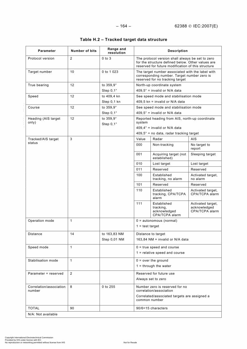
– 164 – 62388 © IEC:2007(E)
Table H.2 – Tracked target data structure
Parameter Number of bits Range and resolution Description
Protocol version 2 0 to 3 The protocol version shall always be set to zero for the structure defined below. Other values are reserved for future modification of this structure
Target number 10 0 to 1 023 The target number associated with the label with corresponding number. Target number zero is reserved for no tracking target
True bearing 12 to 359,9° Step 0,1°
North-up coordinate system 409,5° = invalid or N/A data
Speed 12 to 409,4 kn Step 0,1 kn
See speed mode and stabilisation mode 409,5 kn = invalid or N/A data
Course 12 to 359,9° Step 0,1°
See speed mode and stabilisation mode 409,5° = invalid or N/A data
Heading (AIS target only)
12 to 359,9° Step 0,1°
Reported heading from AIS, north-up coordinate system 409,4° = invalid or N/A data 409,5° = no data, radar tracking target
Value Radar AIS
000 Non-tracking No target to report
001 Acquiring target (not established)
Sleeping target
010 Lost target Lost target
011 Reserved Reserved
100 Established tracking, no alarm
Activated target, no alarm
101 Reserved Reserved
110 Established tracking, CPA/TCPA alarm
Activated target, CPA/TCPA alarm
Tracked/AIS target status
3
111 Established tracking, acknowledged CPA/TCPA alarm
Activated target, acknowledged CPA/TCPA alarm
Operation mode 1 0 = autonomous (normal) 1 = test target
Distance 14 to 163,83 NM Step 0,01 NM
Distance to target 163,84 NM = invalid or N/A data
Speed mode 1 0 = true speed and course 1 = relative speed and course
Stabilisation mode 1 0 = over the ground 1 = through the water
Parameter = reserved 2 Reserved for future use Always set to zero
Correlation/association number
8 0 to 255 Number zero is reserved for no correlation/association Correlated/associated targets are assigned a common number
TOTAL 90 90/6=15 characters
N/A: Not available
Copyright International Electrotechnical Commission Provided by IHS under license with IEC
Not for ResaleNo reproduction or networking permitted without license from IHS
--`,,```,,,,````-`-`,,`,,`,`,,`---

62388 © IEC:2007(E) – 165 –
NOTE Theoretical maximum throughput for IEC 61162-2 connections is calculated with the formula:
targets/second = baud rate/bits per sentence * targets per sentence
38 400/[22+90/6*4)*10]=46 sentences/second (4 targets per sentence) = 187 targets/second
HSC: 60/40=1,5 s/revolution: 280 targets/revolution (9 bits address space enough)
Normal: 60/20=3 s/revolution: 561 targets/revolution (10 bits address space enough)
Overhead for TLB – target label and other sentences are not included in this calculation.
H.2 Optional radar – VDR Ethernet interface using the TCP/IP protocol
H.2.1 Definition
This optional interface is addressing the need to simplify interfacing high-resolution radars to Voyage Data Recorders (VDRs). The digital copying of the original radar presentation improves quality by removing digitising errors and reduces overall system complexity. It is also easily extended into a general method for data transfer via Ethernet.
NOTE The TCP standard is RFC 793: 1981, Transmission Control Protocol (TCP), Internet Activities Board recommended standard. The IP standard is RFC 894: 1984, Internet Protocol on Ethernet Networks, Internet Activities Board elective standard. The Ethernet standard is IEEE 802.3.
NOTE To reduce network load, it is advisable that the presentation data in the radar system are not only captured but also pre-processed and packed before they are sent to the VDR via TCP/IP. Experience has shown that the compression and transmission process of compressed data stresses a radar system far less than the transmission of uncompressed data.
The protocol specification is followed by a description of the principle of presentation acquisition and streaming.
Table H.3 – Description of terms
Term Description
BYTE: The lowest level data element consisting of 8 ordered bits (sometimes called an octet). Bit order is as determined by the computer implementation. Note that the implementation must make any necessary conversion between network bit order and computer bit order
Data packet: A number of bytes that contains a header, an optional sequence of reserved bytes and the actual message content. The header specifies the length of header itself, of reserved bytes and data and will also contain information that allows a number of data packets to be re-assembled into a presentation
Data element: One or more bytes that forms a stand-alone information carrier, i.e. a time stamp, an integer or a character
DWORD: Double word. One unsigned 32-bit integer (in range 0 to 4294967295). The DWORD is constructed from four consecutively transmitted BYTE, where the transmission order on the network is the most significant BYTE first followed by the next most significant BYTE till the least significant BYTE
Presentation: One group of bytes that forms a stand-alone data set, for example one (compressed) radar presentation
Message data: The data contents of a data package
Reserved bytes: A number of bytes in the data packet that may be ignored by the receiver. The reserved bytes may be additional header information that only has meaning for newer versions of the protocol or they may also be used for manufacturer specific purposes
WORD: One unsigned 16-bit integer (in the range 0 to 65535). The WORD is constructed from two consecutively transmitted BYTES, where the transmission order on the network is the most significant BYTE followed by the least significant BYTE
STRING[N]: A sequence of exactly N BYTES, interpreted as a string of characters. The transmission order on the network is the left-most character first. If the string is shorter than N, additional trailing bytes shall be set to zero. All strings in the header are encoded in ISO 18859-1 (ISO Latin 1)
Copyright International Electrotechnical Commission Provided by IHS under license with IEC
Not for ResaleNo reproduction or networking permitted without license from IHS
--`,,```,,,,````-`-`,,`,,`,`,,`---
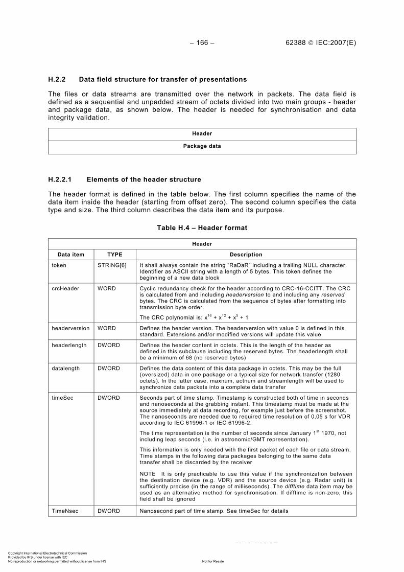
– 166 – 62388 © IEC:2007(E)
H.2.2 Data field structure for transfer of presentations
The files or data streams are transmitted over the network in packets. The data field is defined as a sequential and unpadded stream of octets divided into two main groups - header and package data, as shown below. The header is needed for synchronisation and data integrity validation.
Header
Package data
H.2.2.1 Elements of the header structure
The header format is defined in the table below. The first column specifies the name of the data item inside the header (starting from offset zero). The second column specifies the data type and size. The third column describes the data item and its purpose.
Table H.4 – Header format
Header
Data item TYPE Description
token STRING[6] It shall always contain the string “RaDaR” including a trailing NULL character. Identifier as ASCII string with a length of 5 bytes. This token defines the beginning of a new data block
crcHeader WORD Cyclic redundancy check for the header according to CRC-16-CCITT. The CRC is calculated from and including headerversion to and including any reserved bytes. The CRC is calculated from the sequence of bytes after formatting into transmission byte order.
The CRC polynomial is: x16 + x12 + x5 + 1
headerversion WORD Defines the header version. The headerversion with value 0 is defined in this standard. Extensions and/or modified versions will update this value
headerlength DWORD Defines the header content in octets. This is the length of the header as defined in this subclause including the reserved bytes. The headerlength shall be a minimum of 68 (no reserved bytes)
datalength DWORD Defines the data content of this data package in octets. This may be the full (oversized) data in one package or a typical size for network transfer (1280 octets). In the latter case, maxnum, actnum and streamlength will be used to synchronize data packets into a complete data transfer
timeSec DWORD Seconds part of time stamp. Timestamp is constructed both of time in seconds and nanoseconds at the grabbing instant. This timestamp must be made at the source immediately at data recording, for example just before the screenshot. The nanoseconds are needed due to required time resolution of 0,05 s for VDR according to IEC 61996-1 or IEC 61996-2.
The time representation is the number of seconds since January 1st 1970, not including leap seconds (i.e. in astronomic/GMT representation).
This information is only needed with the first packet of each file or data stream. Time stamps in the following data packages belonging to the same data transfer shall be discarded by the receiver
NOTE It is only practicable to use this value if the synchronization between the destination device (e.g. VDR) and the source device (e.g. Radar unit) is sufficiently precise (in the range of milliseconds). The difftime data item may be used as an alternative method for synchronisation. If difftime is non-zero, this field shall be ignored
TimeNsec DWORD Nanosecond part of time stamp. See timeSec for details
Copyright International Electrotechnical Commission Provided by IHS under license with IEC
Not for ResaleNo reproduction or networking permitted without license from IHS
--`,,```,,,,````-`-`,,`,,`,`,,`---
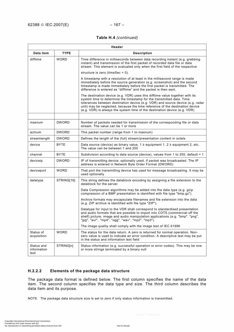
62388 © IEC:2007(E) – 167 –
Table H.4 (continued)
Header
Data item TYPE Description
difftime WORD Time difference in milliseconds between data recording instant (e.g. grabbing instant) and transmission of the first packet of recorded data file or data stream. This element is evaluated only when the first field of the respective
structure is zero (timeSec = 0).
A timestamp with a resolution of at least in the millisecond range is made immediately before the source generation (e.g. screenshot) and the second timestamp is made immediately before the first packet is transmitted. The difference is entered as “difftime” and the packet is then sent.
The destination device (e.g. VDR) uses this difftime value together with its system time to determine the timestamp for the transmitted data. Time tolerances between destination device (e.g. VDR) and source device (e.g. radar unit) may be neglected, because the time reference of the destination device (e.g. VDR) is always the system time of the destination device (e.g. VDR)
maxnum DWORD Number of packets needed for transmission of the corresponding file or data stream. The value can be 1 or more
actnum DWORD This packet number (range from 1 to maxnum)
streamlength DWORD Defines the length of the (full) stream/presentation content in octets
device BYTE Data source (device) as binary value, 1 ≥ equipment 1, 2 ≥ equipment 2, etc. The value can be between 1 and 255
channel BYTE Subdivision according to data source (device), values from 1 to 255, default = 1
deviceip DWORD IP of transmitting device; optionally used, if packet was broadcasted. The IP address is entered in Network Byte Order Format (DWORD)
deviceport WORD That port the transmitting device has used for message broadcasting. It may be used optionally
datatype STRING[16] This string defines the datablock encoding by assigning a file extension to the datablock for the server.
Data Compression algorithms may be added into the data type (e.g. gzip compression of a BMP presentation is identified with file type "bmp.gz").
Archive formats may encapsulate filenames and file extension into the data (e.g. ZIP archive is identified with file type "ZIP").
Datatype for input to the VDR shall correspond to standardised presentation and audio formats that are possible to import into COTS (commercial off the shelf) picture, image and audio manipulation applications (e.g. "bmp", "png", "jpg", "avi"’, "mp4", "ogg", "wav", "mp2", "mp3").
The image quality shall comply with the image test of IEC 61996
Status of acquisition
WORD The status for the data return. A zero is returned for normal operation. Non-zero value is used to indicate an error condition. A descriptive text may be put in the status and information text field
Status and information text
STRING[n] Status information (e.g. successful operation or error codes). This may be one or more strings terminated by a binary null
H.2.2.2 Elements of the package data structure
The package data format is defined below. The first column specifies the name of the data item. The second column specifies the data type and size. The third column describes the data item and its purpose.
NOTE The package data structure size is set to zero if only status information is transmitted.
Copyright International Electrotechnical Commission Provided by IHS under license with IEC
Not for ResaleNo reproduction or networking permitted without license from IHS
--`,,```,,,,````-`-`,,`,,`,`,,`---

– 168 – 62388 © IEC:2007(E)
Table H.5 – Package data format
Package data
Data item TYPE Description
datablock BYTE[datalength] This item is the data either split into pieces or in one block. Size is defined by datalength in the header
NOTE There is no CRC for the data contents as this is partly handled by the TCP/IP layer or by other mechanisms in the contents format. The header has a separate CRC as it is deemed more critical for the correct operation of the system.
H.2.3 Structure of the transfer stream
The transfer may be sent either as a single header and (oversize) datablock, or split into multiple headers and datablocks.
NOTE Multiple data blocks may be used for transmitting devices that have limited internal storage or to control the bandwidth utilization of the network. If very large files are transmitted, it may be useful to divide it into blocks that are transmitted with some time interval so that other traffic also can be interspersed.
H.2.3.1 Single header and package data
The complete file or data stream is transferred as one datablock. The data items actnum and maxnum shall be set to one.
H.2.3.2 Multiple headers and package data
The complete file or data stream is split into a number of datablocks. Each header and datablock is transmitted in increasing order, beginning with the first datablock and ending with the last datablock. Synchronisation is achieved with data items actnum and maxnum.
H.2.3.3 Unknown data types
A receiver that does not understand an incoming data type shall give one alarm for the first message and then silently ignore all incoming data without closing the connection if the receiver is a server.
NOTE This provision is made so that one does not get an infinite number of connections and broken connections and corresponding alarms. The client will normally try to reconnect after 30 s in any case.
If the receiver is a client and does not understand incoming data, it shall give an alarm and immediately close the connection.
NOTE If a radar receives unexpected data on the return link from the VDR server, this can be treated as an error as described here. The VDR should not send any data to the radar.
H.2.4 TCP port and IP addresses
The IP address is freely selectable and is depending on the network configuration of the corresponding equipment manufacturer. The IP address of each presentation source and the VDR has to be coordinated and set manually beforehand.
NOTE Equipment unable to perform an address look-up service should be configured to the same IP sub-net. A router may be used if the equipment is connected on different IP sub-nets.
The default TCP port between radar and VDR for the transfer shall be 7096.
NOTE The radar should support configuration of the VDR port number and IP address.
Copyright International Electrotechnical Commission Provided by IHS under license with IEC
Not for ResaleNo reproduction or networking permitted without license from IHS
--`,,```,,,,````-`-`,,`,,`,`,,`---
62388 © IEC:2007(E) – 169 –
H.2.5 Support for redundancy
Redundancy, if required, is established by utilising two independent networks (with independent power supplies and separate network components). Then each client and server will have two physical interfaces to the two independent networks.
The client and server shall be configured with the same network address, except for the subnet part. The client sends all messages on both networks with identical content. The server will receive and compare the two messages and use one of the copies.
H.2.6 Principle of operation
The principle of operation is described as implementation guidance.
H.2.6.1 VDR as server and radar as client
To satisfy performance standard requirements to the VDR, the VDR has to be configured as a passive listening device. Thus, the VDR is the passive server listening while the radar is the active client connecting and transferring the data.
NOTE The VDR may be set up to accept multiple clients on the same input port. This is necessary if more than one radar is assumed to send its presentations to the VDR. For redundant networks, it is not necessary to support multiple clients on the listening port as the listening ports have to be configured for two different sub-nets.
H.2.6.1.1 Connection management from radar client
The client shall establish a connection to the server immediately after system initialisation. Once the connection is established, the client is responsible for the connection and streaming of data packet to the server.
If the connection attempt fails or connection is lost, the client shall try to establish the connection again. The interval between attempts shall not exceed 30 s. The maximum update interval for the radar presentations in the VDR is 15 s. This corresponds to two intervals.
H.2.6.1.2 Connection management from VDR server
The server shall make the listening port available for data transfers during initialisation.
The manufacturer shall specify the maximum number of client connections for the server. The server shall receive data individually from connected clients and detect any loss of connection from clients.
NOTE The equipment test and performance standard may require alarms to be raised for loss of connection.
The server may in some cases only detect a failed connection by timeout since data was received last time. The server data reception timeout shall not exceed 30 s. The server shall reinitialise the listening port and the receiver software module after timeout for the client.
H.2.6.2 Capturing the screen content
Initially a digital screen copy is used to generate a presentation bitmap. The capturing process shall be independent of the radar application creating the presentation.
H.2.6.3 Conversion into standardised presentation format
The captured presentation bitmap in the system memory (up to this point still a pure bitmap, i.e. as a pixel stream) is then converted into a standardised presentation format. The presentation format may be lossless or lossy. All algorithms shall comply with the receiving equipment requirement, i.e. VDR presentation tests as specified in IEC 61996.
Copyright International Electrotechnical Commission Provided by IHS under license with IEC
Not for ResaleNo reproduction or networking permitted without license from IHS
--`,,```,,,,````-`-`,,`,,`,`,,`---
– 170 – 62388 © IEC:2007(E)
NOTE Standardised presentation formats are possible to import into COTS (commercial off the shelf) picture and presentation manipulation applications.
H.2.6.4 Error handling
The server shall ensure data integrity at reception by verification of the header including token, version, consistency of data fields and the header CRC. Erroneous data reception shall be processed and indicated according to individual equipment standard (for VDR according to IEC 61996).
NOTE Consistency of data fields may depend on application. However, strings can be checked against containing illegal characters, message sequence numbers can be checked, etc.
H.2.6.5 Transmission of a presentation
The client transmission of a presentation may occur at any time when the connection is open. The message header information is sufficient for the server to decode the data stream and reassemble the presentation and its associated header information data.
A presentation shall be encoded and transferred as one single (oversized) data packet with defined header, or as a set of packets with individually specified sizes.
H.2.6.6 Device identification
All clients shall be configured with a unique device identification (1–255) to allow the server to unambiguously identify the source of the received packets.
H.2.7 Interface test and test results
The radar is tested as a client and the VDR as a server.
H.2.7.1 Test of client
H.2.7.1.1 Description
The test set-up is a controllable server and the equipment under test. The following tests shall be performed and passed.
H.2.7.1.2 Connection establishment test
Remove server from network and power up client. Verify that client performs reconnection attempts as specified.
Connect server and verify that connection is established.
Test that the presentation transfer time is no more than 5 s.
H.2.7.1.3 Lost connection test
Power down or physically remove server from network and verify that client detects connection failure. This will normally require the transmission of some data from client.
Reconnect server and verify that client really is able to send data as specified. Inspect headers and verify that they are according to the data format specification. Verify that time stamp is increased.
Break connection in the middle of a transfer. Verify that the client equipment continues to operate and tries to reconnect. The client may also raise an alarm.
Copyright International Electrotechnical Commission Provided by IHS under license with IEC
Not for ResaleNo reproduction or networking permitted without license from IHS
--`,,```,,,,````-`-`,,`,,`,`,,`---
62388 © IEC:2007(E) – 171 –
H.2.7.1.4 Presentation quality test
Apply the test presentations defined in the presentation test of IEC 61996 on the display. Verify that the presentations transfer without degradation for lossless transfers, or within presentation test limits for lossy transfers.
H.2.7.2 Test of server
The test set-up is a controllable client server and the equipment under test. The client shall be able to generate the following and tests shall be made that check the correct functioning of the server in these cases.
H.2.7.2.1 Connection establishment test
Remove clients from network and power up server. Verify that server starts up as specified. Verify that configured clients without connection raise alarm.
Connect client(s) and verify that server enters normal operation.
H.2.7.2.2 Lost connection test
Break connection in the middle of a transfer. Verify that the server raises an alarm and continues to operate.
H.2.7.2.3 Single message transfer test
Test transfer of at least one presentation streamed as one packet.
H.2.7.2.4 Multiple message transfer test
Test transfer of at least one presentation streamed into a minimum of 5 packets.
H.2.7.2.5 Multiple client test
Test simultaneous transfers from the maximum allowed number of clients according to the manufacturer.
H.2.7.2.6 Erroneous input test
Test incorrect length set in the header.
H.2.7.2.7 Undefined header test
Test header version set to undefined value in the header.
Copyright International Electrotechnical Commission Provided by IHS under license with IEC
Not for ResaleNo reproduction or networking permitted without license from IHS
--`,,```,,,,````-`-`,,`,,`,`,,`---
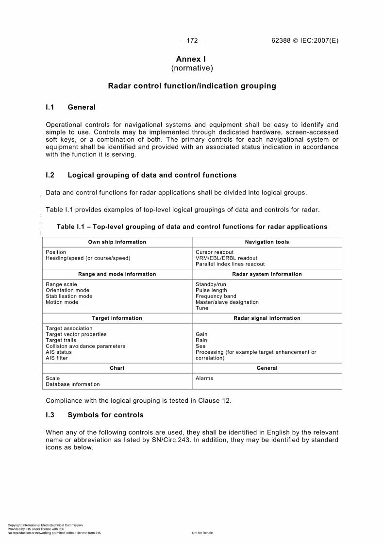
– 172 – 62388 © IEC:2007(E)
Annex I (normative)
Radar control function/indication grouping
I.1 General
Operational controls for navigational systems and equipment shall be easy to identify and simple to use. Controls may be implemented through dedicated hardware, screen-accessed soft keys, or a combination of both. The primary controls for each navigational system or equipment shall be identified and provided with an associated status indication in accordance with the function it is serving.
I.2 Logical grouping of data and control functions
Data and control functions for radar applications shall be divided into logical groups.
Table I.1 provides examples of top-level logical groupings of data and controls for radar.
Table I.1 – Top-level grouping of data and control functions for radar applications
Own ship information Navigation tools
Position Heading/speed (or course/speed)
Cursor readout VRM/EBL/ERBL readout Parallel index lines readout
Range and mode information Radar system information
Range scale Orientation mode Stabilisation mode Motion mode
Standby/run Pulse length Frequency band Master/slave designation Tune
Target information Radar signal information
Target association Target vector properties Target trails Collision avoidance parameters AIS status AIS filter
Gain Rain Sea Processing (for example target enhancement or correlation)
Chart General
Scale Database information
Alarms
Compliance with the logical grouping is tested in Clause 12.
I.3 Symbols for controls
When any of the following controls are used, they shall be identified in English by the relevant name or abbreviation as listed by SN/Circ.243. In addition, they may be identified by standard icons as below.
Copyright International Electrotechnical Commission Provided by IHS under license with IEC
Not for ResaleNo reproduction or networking permitted without license from IHS
--`,,```,,,,````-`-`,,`,,`,`,,`---
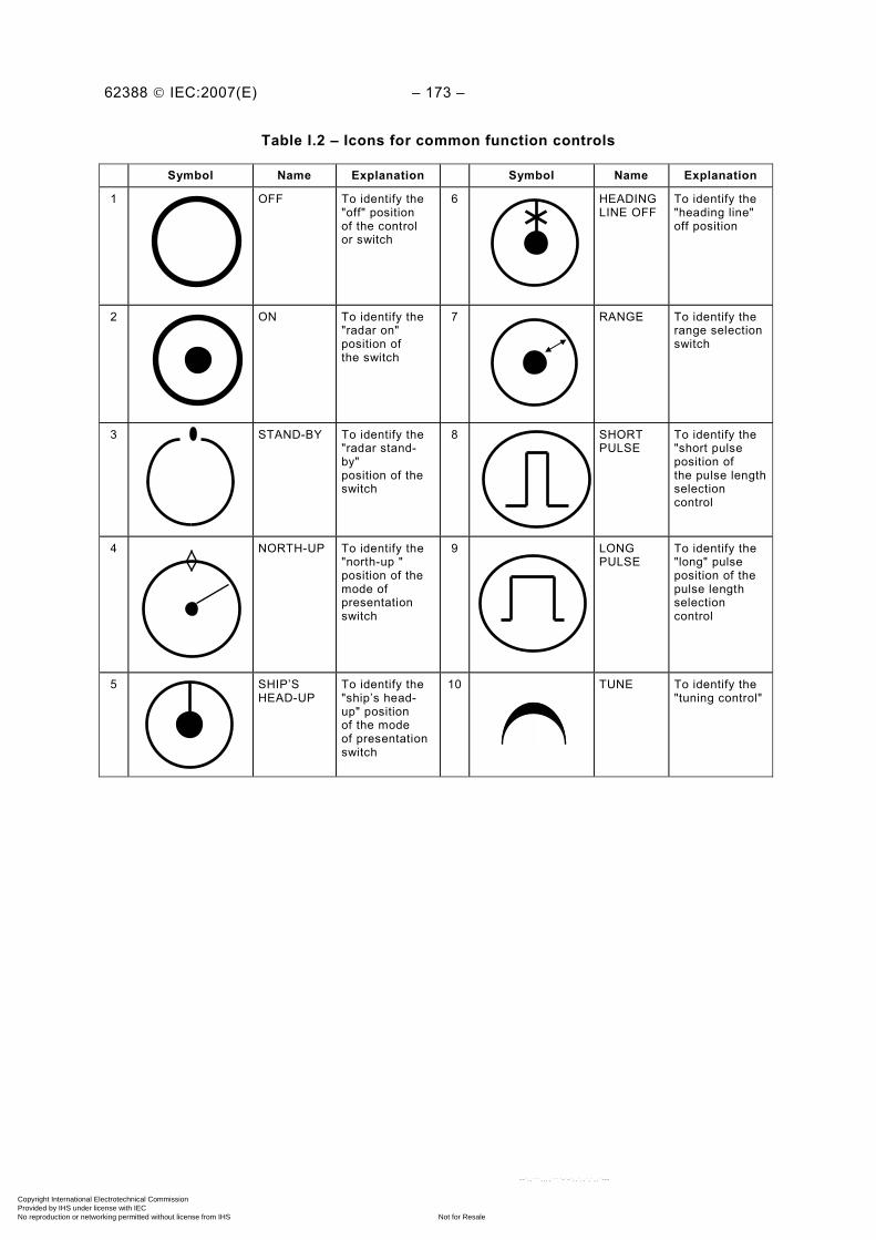
62388 © IEC:2007(E) – 173 –
Table I.2 – Icons for common function controls
Symbol Name Explanation Symbol Name Explanation
1 OFF To identify the "off" position of the control or switch
6 HEADING LINE OFF
To identify the "heading line" off position
2 ON To identify the "radar on" position of the switch
7 RANGE To identify the range selectionswitch
3 STAND-BY To identify the "radar stand-by" position of the switch
8 SHORT PULSE
To identify the "short pulse position of the pulse lengthselection control
4 NORTH-UP To identify the "north-up " position of the mode of presentation switch
9 LONG PULSE
To identify the "long" pulse position of the pulse length selection control
5 SHIP’S HEAD-UP
To identify the "ship’s head- up" position of the mode of presentationswitch
10 TUNE To identify the "tuning control"
Copyright International Electrotechnical Commission Provided by IHS under license with IEC
Not for ResaleNo reproduction or networking permitted without license from IHS
--`,,```,,,,````-`-`,,`,,`,`,,`---
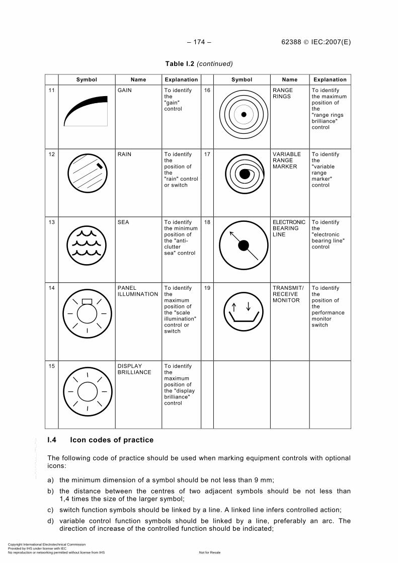
– 174 – 62388 © IEC:2007(E)
Table I.2 (continued)
Symbol Name Explanation Symbol Name Explanation
11 GAIN To identify the "gain" control
16 RANGE RINGS
To identify the maximumposition of the "range rings brilliance" control
12 RAIN To identify the position of the "rain" controlor switch
17 VARIABLE RANGE MARKER
To identify the "variable range marker" control
13 SEA To identify the minimumposition of the "anti-clutter sea" control
18 ELECTRONIC BEARING LINE
To identify the "electronic bearing line"control
14 PANEL ILLUMINATION
To identify the maximum position of the "scale illumination"control or switch
19 TRANSMIT/RECEIVE MONITOR
To identify the position of the performance monitor switch
15 DISPLAY BRILLIANCE
To identify the maximum position of the "displaybrilliance" control
I.4 Icon codes of practice
The following code of practice should be used when marking equipment controls with optional icons:
a) the minimum dimension of a symbol should be not less than 9 mm; b) the distance between the centres of two adjacent symbols should be not less than
1,4 times the size of the larger symbol; c) switch function symbols should be linked by a line. A linked line infers controlled action; d) variable control function symbols should be linked by a line, preferably an arc. The
direction of increase of the controlled function should be indicated;
Copyright International Electrotechnical Commission Provided by IHS under license with IEC
Not for ResaleNo reproduction or networking permitted without license from IHS
--`,,```,,,,````-`-`,,`,,`,`,,`---

62388 © IEC:2007(E) – 175 –
e) symbols should be presented with a high contrast against their background; f) the various elements of a symbol should have a fixed ratio one to another; g) multiple functions of controls and switch positions may be indicated by a combined
symbol; h) where concentric controls or switches are fitted, the outer of the symbols should refer to
the larger diameter control.
Copyright International Electrotechnical Commission Provided by IHS under license with IEC
Not for ResaleNo reproduction or networking permitted without license from IHS
--`,,```,,,,````-`-`,,`,,`,`,,`---
– 176 – 62388 © IEC:2007(E)
Annex J (normative)
Presentation colours and symbols
This annex specifies the harmonised symbols to be used for the presentation of navigation related information on all shipborne navigational systems and equipment in conformance with guidelines published by the IMO and provided in SN/Circ.243.
All text in this annex whose wording is identical to text contained in IMO SN/Circ.243 is printed in italics. The IMO reference is made up of two parts; a prefix representing the IMO instrument, followed by the paragraph number, displayed as, for example: (SN243/1).
J.1 Purpose
(SN243/1) The purpose of this annex is to provide guidance on the appropriate use of navigation-related symbols and the use of colour to achieve a harmonized and consistent presentation on all shipborne navigational systems and equipment.
J.2 Scope
(SN243/2) The use of these guidelines will insure that the symbols used for the display of navigation-related information on all shipborne navigational systems and equipment are presented in a consistent and uniform manner.
J.3 Application
(SN243/3) The symbols listed in Tables J.2 through J.6 shall take precedence over and replace symbols which are currently contained in existing performance standards for individual navigational systems and equipment, unless otherwise specified in this standard to reduce degradation of the radar image (for example own ship symbol). Where a standard symbol is not available, another symbol may be used but this symbol shall not conflict with the symbols listed in this annex.
J.4 Navigation related symbols
For the application of the symbols listed in Tables J.2 through J.6, the following shall be considered:
• the symbols are provided to meet IMO guidelines for all displays on the bridge of a ship and to support additional functionality provided by system manufacturers;
• specific colours are only associated with symbols where IMO has mandated the use of the colour red for dangerous targets and should also be used for symbols with an unacknowledged alarm status;
• the presentation of the radar image, chart information (if provided) and navigation-related symbols shall use contrasting colours on a dark background: – the heading line and own ship location shall be readily identified; – colours used for the presentation of tracked target symbols and AIS target symbols
shall be consistent. Colour shades may be used to distinguish target classification; – colours used for the presentation of all symbols representing operational information
shall be discriminated from the colours used for the presentation of the radar image, target trails, additional processed radar information and charted information;
Copyright International Electrotechnical Commission Provided by IHS under license with IEC
Not for ResaleNo reproduction or networking permitted without license from IHS
--`,,```,,,,````-`-`,,`,,`,`,,`---

62388 © IEC:2007(E) – 177 –
– colours used for radar images shall ensure that a processed radar image is readily identified;
– colour is not permitted as a means to differentiate unprocessed radar signal intensity; shades of the basic colour may be used for this purpose;
– colours and symbols used for navigation related information shall not, as far as practical, mask, degrade or obscure the radar image;
– colours used for chart related features on a chart radar shall as far as practical, conform to IMO recommendations;
– colours and line styles used for navigation tools, for example EBL, VRM, and index lines, shall be distinguished from other presented information. Where multiple navigation tools are provided, for example two EBL lines, colour may be used in addition to line style, to aid the identification of individual navigation graphic;
– colour used for the cursor shall assist in its location on the presentation; – colour fill for symbols is not recommended if the radar image is unduly masked,
obscured or degraded; – colour combined with presentation transparency techniques to discriminate the radar
image is encouraged; – colours used for the presentation of all symbols representing operational information
shall support readability from typical user positions (i.e. reading distance and viewing angles) under all ambient light conditions (day, dusk and night), likely to be experienced on the bridge of a ship, and with due consideration to the night vision of the officer of the watch;
• sizes specified for symbols (and associated text) assume a nominal viewing distance of 1 m. Sizes may be adjusted in proportion to the sizes of the operational display area or viewing distances specified in the manufacturer’s documentation;
• where the thickness of line styles is specified, a "thick" line style shall be at least twice the thickness of the "thin" line style;
• where a colour is described as “required”, the use of that colour is mandatory;
• colours that are recommended in general IEC standards are not mandatory, however these colours shall as a minimum be made available. If alternative colours are provided, the user may select from these alternative colours for the task in hand.
J.5 Guidelines for the display of navigational information on radar by means of radar maps
J.5.1 Application
Radar maps shall conform as far as is practicable to the following principles:
– the map information displayed is limited to items in Table J.1; – the map symbols used to display the information are similar in shape to those defined in
Appendix 2 of IHO S-52, Figure 1, items 1 to 40; – the map colours used to display the information are listed in Table J.1. Where these are
not automatically selected, the operating manual shall clearly show how this is to be achieved. Alternatively, radar maps may use the colours specified for chart features in IHO S-52.
J.5.2 Navigation symbols for use with radar maps
Navigation symbols for use with radar maps shall be similar to those used for the chart radar.
The number of types of navigational symbols used shall be limited to provide simple operation.
Copyright International Electrotechnical Commission Provided by IHS under license with IEC
Not for ResaleNo reproduction or networking permitted without license from IHS
--`,,```,,,,````-`-`,,`,,`,`,,`---

– 178 – 62388 © IEC:2007(E)
The shape of these navigational symbols shall be similar to those used for the chart radar.
Table J.1 – Features and colours to be used for radar maps
Mapping feature Colour to be used
Coastline (high water) White
Own ship safety contour Grey
Indication of isolated underwater dangers of depths less than the safety contour which lie within the safe water defined by the safety contour
Magenta
Indication of isolated dangers which lie within the safe water defined by the safety contour such as bridges, overhead wires, etc.
Magenta or grey
Buoys and beacons, whether or not these are being used as aids to navigation Red or green
Traffic routeing systems Magenta
Prohibited and restricted areas Magenta
Boundaries of fairways and channels Grey
Radar background Black or blue
NOTE When the “own ship safety contour” feature is used, the dangerous side should be clearly indicated, for example by colour fill, hatching, double lines, broken line, etc., on the dangerous side.
Table J.2 – Own ship symbols
Symbol name and description Symbol graphic(s)
2.1 a Own ship – true scaled outline
The user may select to present own ship as a true scaled outline oriented in the direction of heading relative to CCRP and drawn using a thick solid line style with the same basic colour used for own ship symbols.
Automatic selection of the true scaled outline is permitted (see 7.2.2).
The true scaled outline shall not be used when heading is unknown in a gyro/THD-stabilised mode, or when the beam of the outline is less than 6 mm.
In the radar mode, the true scale outline shall be used together with own ship minimised symbol.
NOTE A loss of heading will force the radar into head-up mode (see 9.2.1.2.1a)); in this case, the true scaled outline is still permitted.
(SN243)
Copyright International Electrotechnical Commission Provided by IHS under license with IEC
Not for ResaleNo reproduction or networking permitted without license from IHS
--`,,```,,,,````-`-`,,`,,`,`,,`---
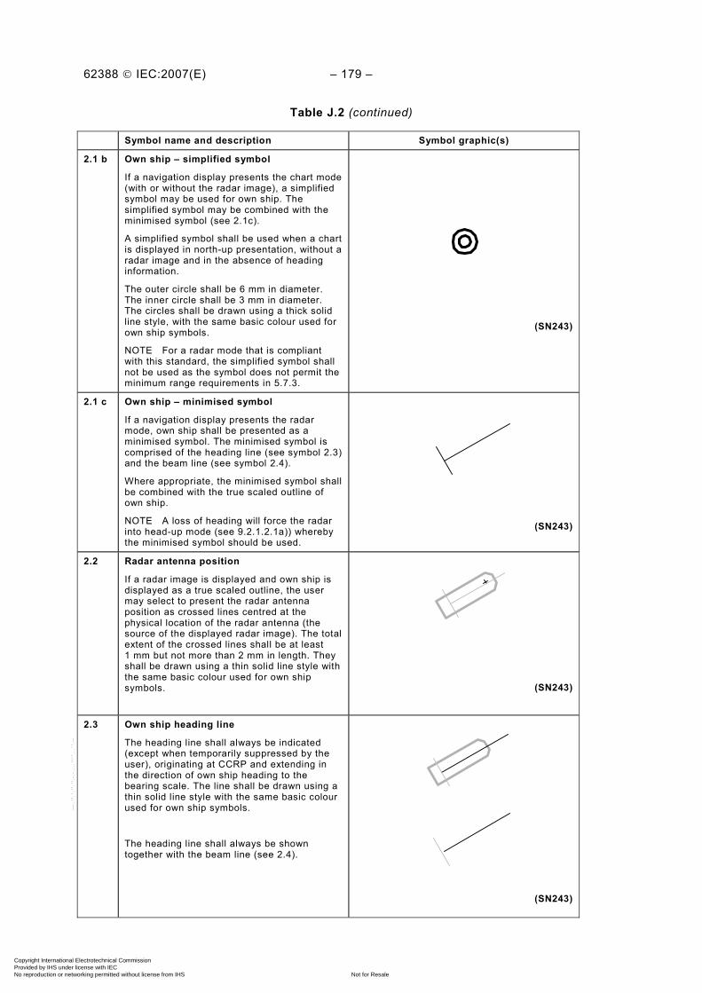
62388 © IEC:2007(E) – 179 –
Table J.2 (continued)
Symbol name and description Symbol graphic(s)
2.1 b Own ship – simplified symbol
If a navigation display presents the chart mode (with or without the radar image), a simplified symbol may be used for own ship. The simplified symbol may be combined with the minimised symbol (see 2.1c).
A simplified symbol shall be used when a chart is displayed in north-up presentation, without a radar image and in the absence of heading information.
The outer circle shall be 6 mm in diameter. The inner circle shall be 3 mm in diameter. The circles shall be drawn using a thick solid line style, with the same basic colour used for own ship symbols.
NOTE For a radar mode that is compliant with this standard, the simplified symbol shall not be used as the symbol does not permit the minimum range requirements in 5.7.3.
(SN243)
2.1 c Own ship – minimised symbol
If a navigation display presents the radar mode, own ship shall be presented as a minimised symbol. The minimised symbol is comprised of the heading line (see symbol 2.3) and the beam line (see symbol 2.4).
Where appropriate, the minimised symbol shall be combined with the true scaled outline of own ship.
NOTE A loss of heading will force the radar into head-up mode (see 9.2.1.2.1a)) whereby the minimised symbol should be used.
(SN243)
2.2 Radar antenna position
If a radar image is displayed and own ship is displayed as a true scaled outline, the user may select to present the radar antenna position as crossed lines centred at the physical location of the radar antenna (the source of the displayed radar image). The total extent of the crossed lines shall be at least 1 mm but not more than 2 mm in length. They shall be drawn using a thin solid line style with the same basic colour used for own ship symbols.
(SN243)
2.3 Own ship heading line
The heading line shall always be indicated (except when temporarily suppressed by the user), originating at CCRP and extending in the direction of own ship heading to the bearing scale. The line shall be drawn using a thin solid line style with the same basic colour used for own ship symbols.
The heading line shall always be shown together with the beam line (see 2.4).
(SN243)
Copyright International Electrotechnical Commission Provided by IHS under license with IEC
Not for ResaleNo reproduction or networking permitted without license from IHS
--`,,```,,,,````-`-`,,`,,`,`,,`---
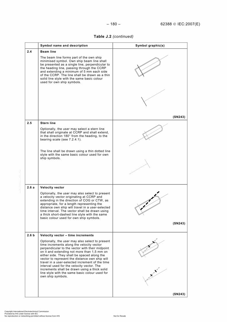
– 180 – 62388 © IEC:2007(E)
Table J.2 (continued)
Symbol name and description Symbol graphic(s)
2.4 Beam line
The beam line forms part of the own ship minimised symbol. Own ship beam line shall be presented as a single line, perpendicular to the heading line, passing through the CCRP and extending a minimum of 5 mm each side of the CCRP. The line shall be drawn as a thin solid line style with the same basic colour used for own ship symbols.
(SN243)
2.5 Stern line
Optionally, the user may select a stern line that shall originate at CCRP and shall extend, in the direction 180° from the heading, to the bearing scale (see 7.2.4.1).
The line shall be drawn using a thin dotted line style with the same basic colour used for own ship symbols.
2.6 a Velocity vector
Optionally, the user may also select to present a velocity vector originating at CCRP and extending in the direction of COG or CTW, as appropriate, for a length representing the distance own ship will travel in a user-selected time interval. The vector shall be drawn using a thick short-dashed line style with the same basic colour used for own ship symbols.
(SN243)
2.6 b Velocity vector – time increments
Optionally, the user may also select to present time increments along the velocity vector perpendicular to the vector with their midpoint on it and extending not more than 1,5 mm on either side. They shall be spaced along the vector to represent the distance own ship will travel in a user-selected increment of the time interval used for the velocity vector. The increments shall be drawn using a thick solid line style with the same basic colour used for own ship symbols.
(SN243)
Copyright International Electrotechnical Commission Provided by IHS under license with IEC
Not for ResaleNo reproduction or networking permitted without license from IHS
--`,,```,,,,````-`-`,,`,,`,`,,`---

62388 © IEC:2007(E) – 181 –
Table J.2 (continued)
Symbol name and description Symbol graphic(s)
2.6 c Velocity vector – Stabilisation indicator
Optionally, the user may select to present a stabilisation indicator, positioned at the end of the velocity vector.
The ground stabilisation indicator shall be presented as a double arrowhead. The water stabilisation indicator shall be presented as a single arrowhead. The arrowheads shall extend at least 1 mm but not more than 1,5 mm on either side of the vector (i.e. measured perpendicular to it).
The arrowhead(s) shall be drawn using a thick solid line style with the same basic colour used for own ship symbols.
(SN243)
2.6 d Path predictor
Optionally, the user may select to present a path predictor, in place of a velocity vector, as a curved line originating at CCRP and extending along the predicted path over ground own ship will travel in the time interval used for the velocity vector. The path shall be drawn using a thin long-dashed line style with the same basic colour used for own ship symbols.
(SN243)
2.7 a Past track
The user may select to present a past track for the primary and/or secondary positioning sources. The past track shall be presented as line connecting own ship current and past positions. The primary past track shall be drawn using a thick solid line style with the same basic colour used for own ship symbol. The secondary past track shall be drawn using a thin solid line style with the same basic colour used for own ship symbols.
(SN243)
Copyright International Electrotechnical Commission Provided by IHS under license with IEC
Not for ResaleNo reproduction or networking permitted without license from IHS
--`,,```,,,,````-`-`,,`,,`,`,,`---

– 182 – 62388 © IEC:2007(E)
Table J.2 (continued)
Symbol name and description Symbol graphic(s)
2.7 b Past track – time increments
Optionally, time increments along the past track may be shown. The time increments shall be presented as single lines perpendicular to the past track with their midpoint on it and extending at least 1 mm but not more than 1,5 mm on either side. They shall be spaced along the past track to represent the distance own ship travelled in the user-selected increment of the time interval used for the velocity vector. The time increments for the primary past track shall be drawn using a solid line style.
(SN243)
2.7 c Past track – past positions
Alternatively, the user may select to present past positions along the past track in place of time increments. Past positions shall be drawn as small filled circular symbols with a diameter of not more than 1,5 mm, with the same basic colour used for own ship symbols.
Copyright International Electrotechnical Commission Provided by IHS under license with IEC
Not for ResaleNo reproduction or networking permitted without license from IHS
--`,,```,,,,````-`-`,,`,,`,`,,`---
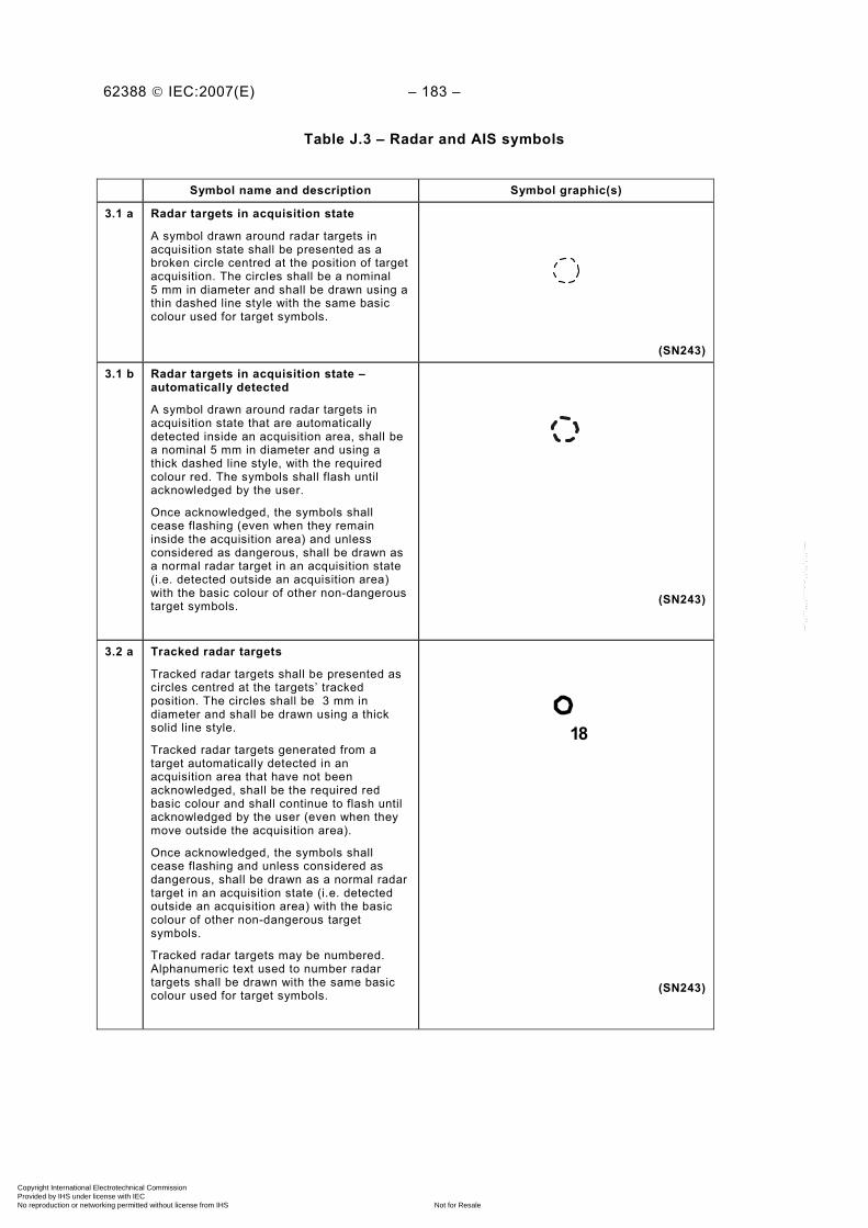
62388 © IEC:2007(E) – 183 –
Table J.3 – Radar and AIS symbols
Symbol name and description Symbol graphic(s)
3.1 a Radar targets in acquisition state
A symbol drawn around radar targets in acquisition state shall be presented as a broken circle centred at the position of target acquisition. The circles shall be a nominal 5 mm in diameter and shall be drawn using a thin dashed line style with the same basic colour used for target symbols.
(SN243)
3.1 b Radar targets in acquisition state – automatically detected
A symbol drawn around radar targets in acquisition state that are automatically detected inside an acquisition area, shall be a nominal 5 mm in diameter and using a thick dashed line style, with the required colour red. The symbols shall flash until acknowledged by the user.
Once acknowledged, the symbols shall cease flashing (even when they remain inside the acquisition area) and unless considered as dangerous, shall be drawn as a normal radar target in an acquisition state (i.e. detected outside an acquisition area) with the basic colour of other non-dangerous target symbols.
(SN243)
3.2 a Tracked radar targets
Tracked radar targets shall be presented as circles centred at the targets’ tracked position. The circles shall be 3 mm in diameter and shall be drawn using a thick solid line style.
Tracked radar targets generated from a target automatically detected in an acquisition area that have not been acknowledged, shall be the required red basic colour and shall continue to flash until acknowledged by the user (even when they move outside the acquisition area).
Once acknowledged, the symbols shall cease flashing and unless considered as dangerous, shall be drawn as a normal radar target in an acquisition state (i.e. detected outside an acquisition area) with the basic colour of other non-dangerous target symbols.
Tracked radar targets may be numbered. Alphanumeric text used to number radar targets shall be drawn with the same basic colour used for target symbols.
18
(SN243)
Copyright International Electrotechnical Commission Provided by IHS under license with IEC
Not for ResaleNo reproduction or networking permitted without license from IHS
--`,,```,,,,````-`-`,,`,,`,`,,`---

– 184 – 62388 © IEC:2007(E)
Table J.3 (continued)
Symbol name and description Symbol graphic(s)
3.2 b Tracked radar targets – alternative
Alternatively, tracked radar targets may be presented as filled circles of not more than 2 mm in diameter.
18
(SN243)
3.2 c Tracked radar targets – dangerous targets
Tracked radar targets designated as dangerous targets may be presented using 5 mm diameter circles, and shall flash until acknowledged by the user. The required colour shall be red.
Once acknowledged, the symbols shall cease flashing, but shall still be drawn with the required basic colour red until the target(s) cease to be a danger.
18
(SN243)
3.3 Reference targets
Tracked radar targets designated as reference targets shall be labelled with the letter “R” adjacent to the symbol. Multiple reference targets shall be numbered as “R1”, “R2”, “R3”, etc.
The reference target labels shall be drawn with the same basic colour used for target symbols.
R4 18
(SN243)
(SN243)
3.4 Sleeping AIS targets
Sleeping AIS targets shall be presented as acute isosceles triangles oriented to the targets’ reported heading (or COG if heading is not reported) and centred at the targets’ reported position. The base of the triangles shall be 3 mm and the height shall be 4,5 mm. The triangles shall be drawn using a thick solid line style (or a broken line if a collision avoidance computation cannot be done) with the same basic colour used for target symbols.
A sleeping AIS target with neither a reported heading nor COG shall be oriented toward the top of the operational display area.
Sleeping AIS target with neither reported heading nor COG:
Copyright International Electrotechnical Commission Provided by IHS under license with IEC
Not for ResaleNo reproduction or networking permitted without license from IHS
--`,,```,,,,````-`-`,,`,,`,`,,`---
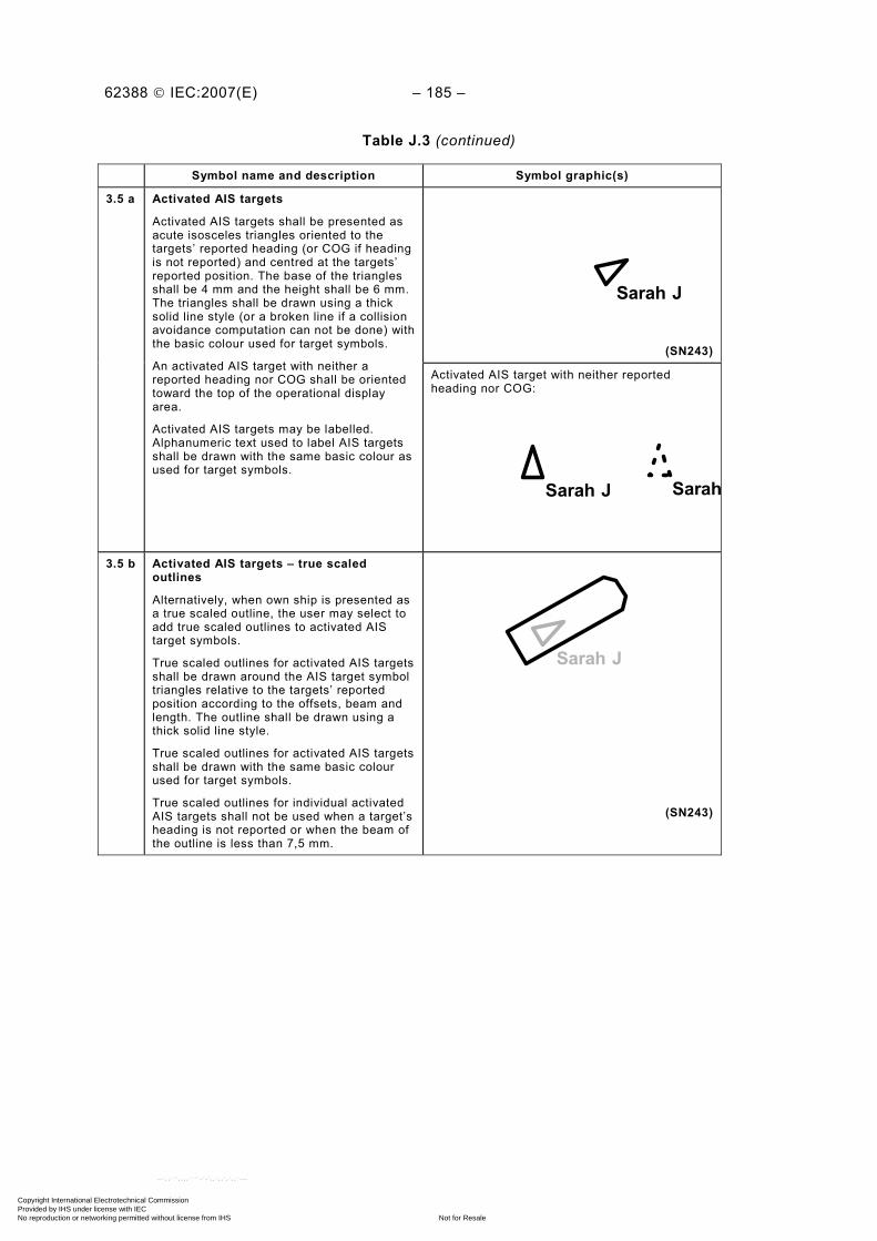
62388 © IEC:2007(E) – 185 –
Table J.3 (continued)
Symbol name and description Symbol graphic(s)
Sarah J
(SN243)
3.5 a Activated AIS targets
Activated AIS targets shall be presented as acute isosceles triangles oriented to the targets’ reported heading (or COG if heading is not reported) and centred at the targets’ reported position. The base of the triangles shall be 4 mm and the height shall be 6 mm. The triangles shall be drawn using a thick solid line style (or a broken line if a collision avoidance computation can not be done) with the basic colour used for target symbols.
An activated AIS target with neither a reported heading nor COG shall be oriented toward the top of the operational display area.
Activated AIS targets may be labelled. Alphanumeric text used to label AIS targets shall be drawn with the same basic colour as used for target symbols.
Activated AIS target with neither reported heading nor COG:
Sarah J Sarah
3.5 b Activated AIS targets – true scaled outlines
Alternatively, when own ship is presented as a true scaled outline, the user may select to add true scaled outlines to activated AIS target symbols.
True scaled outlines for activated AIS targets shall be drawn around the AIS target symbol triangles relative to the targets’ reported position according to the offsets, beam and length. The outline shall be drawn using a thick solid line style.
True scaled outlines for activated AIS targets shall be drawn with the same basic colour used for target symbols.
True scaled outlines for individual activated AIS targets shall not be used when a target’s heading is not reported or when the beam of the outline is less than 7,5 mm.
Sarah J
(SN243)
Copyright International Electrotechnical Commission Provided by IHS under license with IEC
Not for ResaleNo reproduction or networking permitted without license from IHS
--`,,```,,,,````-`-`,,`,,`,`,,`---
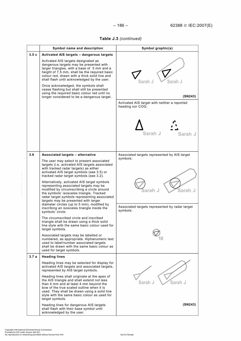
– 186 – 62388 © IEC:2007(E)
Table J.3 (continued)
Symbol name and description Symbol graphic(s)
Sarah JSarah J
(SN243)
3.5 c Activated AIS targets – dangerous targets
Activated AIS targets designated as dangerous targets may be presented with larger triangles, with a base of 5 mm and a height of 7,5 mm, shall be the required basic colour red, drawn with a thick solid line and shall flash until acknowledged by the user.
Once acknowledged, the symbols shall cease flashing but shall still be presented using the required basic colour red until no longer considered to be a dangerous target.
Activated AIS target with neither a reported heading nor COG:
Sarah J Sarah J
Associated targets represented by AIS target symbols:
Sarah J Sarah J
3.6 Associated targets – alternative
The user may select to present associated targets (i.e. activated AIS targets associated with tracked radar targets) as either activated AIS target symbols (see 3.5) or tracked radar target symbols (see 3.2).
Alternatively, activated AIS target symbols representing associated targets may be modified by circumscribing a circle around the symbols’ isosceles triangle. Tracked radar target symbols representing associated targets may be presented with larger diameter circles (up to 5 mm), modified by inscribing an isosceles triangle inside the symbols’ circle.
The circumscribed circle and inscribed triangle shall be drawn using a thick solid line style with the same basic colour used for target symbols.
Associated targets may be labelled or numbered, as appropriate. Alphanumeric text used to label/number associated targets shall be drawn with the same basic colour as used for target symbols.
Associated targets represented by radar target symbols:
18
3.7 a Heading lines
Heading lines may be selected for display for activated AIS targets and associated targets, represented by AIS target symbols.
Heading lines shall originate at the apex of the AIS triangle and shall extend not less than 4 mm and at least 4 mm beyond the bow of the true scaled outline when it is used. They shall be drawn using a solid line style with the same basic colour as used for target symbols.
Heading lines for dangerous AIS targets shall flash with their base symbol until acknowledged by the user.
Sarah J Sarah J
(SN243)
Copyright International Electrotechnical Commission Provided by IHS under license with IEC
Not for ResaleNo reproduction or networking permitted without license from IHS
--`,,```,,,,````-`-`,,`,,`,`,,`---

62388 © IEC:2007(E) – 187 –
Table J.3 (continued)
Symbol name and description Symbol graphic(s)
3.7 b Heading lines – turn indicators
The user may select to display turn indicators for activated AIS targets and associated targets represented by AIS target symbols.
Turn indicators shall be presented as a single line extending at least 1 mm but not more than 2 mm perpendicular to the heading line in the direction of turn. The indicator shall be drawn using a thin solid line style with the same basic colour as used for their target symbols.
Turn indicators for dangerous targets shall be the required colour red (until no longer dangerous) and shall flash with their symbol until acknowledged by the user.
Sarah J Sarah J
(SN243)
Radar target velocity vectors:
18 18
(SN243)
AIS target velocity vectors:
Sarah J Sarah J
(SN243)
3.8 a Velocity vectors
Velocity vectors for targets may be selected for display.
Velocity vectors shall be presented as single lines originating at the targets’ tracked/reported position and extending in the direction of course CTW or COG, as appropriate, for a length representing the distance the target will travel in the time interval used for own ship’s velocity vector. Vectors shall be drawn using a thick short-dashed line style with the same basic colour used for target symbols.
Velocity vectors for dangerous targets shall be the required red basic colour and shall flash with their base target symbols until acknowledged by the user.
Once acknowledged, the symbols shall cease flashing and unless considered as dangerous, shall assume the basic colour of other non-dangerous target symbols.
Associated target velocity vectors:
Sarah J Sarah J 18
Copyright International Electrotechnical Commission Provided by IHS under license with IEC
Not for ResaleNo reproduction or networking permitted without license from IHS
--`,,```,,,,````-`-`,,`,,`,`,,`---
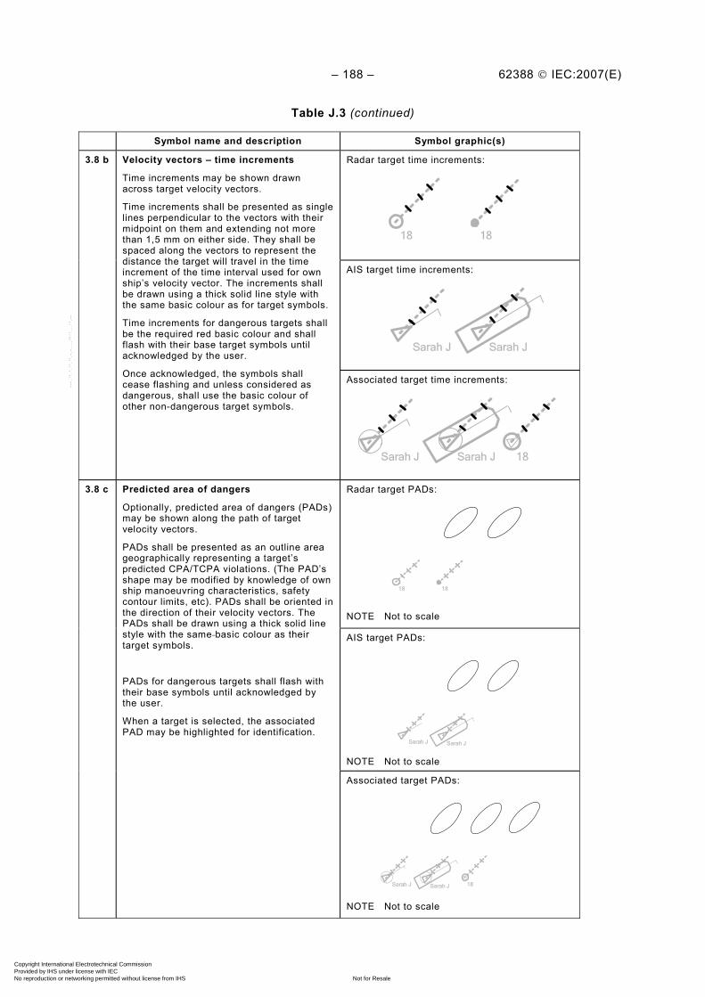
– 188 – 62388 © IEC:2007(E)
Table J.3 (continued)
Symbol name and description Symbol graphic(s)
Radar target time increments:
18 18
AIS target time increments:
Sarah J Sarah J
3.8 b Velocity vectors – time increments
Time increments may be shown drawn across target velocity vectors.
Time increments shall be presented as single lines perpendicular to the vectors with their midpoint on them and extending not more than 1,5 mm on either side. They shall be spaced along the vectors to represent the distance the target will travel in the time increment of the time interval used for own ship’s velocity vector. The increments shall be drawn using a thick solid line style with the same basic colour as for target symbols.
Time increments for dangerous targets shall be the required red basic colour and shall flash with their base target symbols until acknowledged by the user.
Once acknowledged, the symbols shall cease flashing and unless considered as dangerous, shall use the basic colour of other non-dangerous target symbols.
Associated target time increments:
Sarah J Sarah J 18
Radar target PADs:
18 18
NOTE Not to scale
AIS target PADs:
Sarah J Sarah J NOTE Not to scale
3.8 c Predicted area of dangers
Optionally, predicted area of dangers (PADs) may be shown along the path of target velocity vectors.
PADs shall be presented as an outline area geographically representing a target’s predicted CPA/TCPA violations. (The PAD’s shape may be modified by knowledge of own ship manoeuvring characteristics, safety contour limits, etc). PADs shall be oriented in the direction of their velocity vectors. The PADs shall be drawn using a thick solid line style with the same basic colour as their target symbols.
PADs for dangerous targets shall flash with their base symbols until acknowledged by the user.
When a target is selected, the associated PAD may be highlighted for identification.
Associated target PADs:
Sarah J Sarah J 18
NOTE Not to scale
Copyright International Electrotechnical Commission Provided by IHS under license with IEC
Not for ResaleNo reproduction or networking permitted without license from IHS
--`,,```,,,,````-`-`,,`,,`,`,,`---
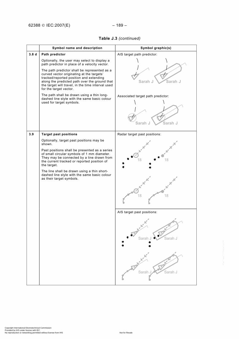
62388 © IEC:2007(E) – 189 –
Table J.3 (continued)
Symbol name and description Symbol graphic(s)
3.8 d Path predictor
Optionally, the user may select to display a path predictor in place of a velocity vector.
The path predictor shall be represented as a curved vector originating at the targets’ tracked/reported position and extending along the predicted path over the ground that the target will travel, in the time interval used for the target vector.
The path shall be drawn using a thin long-dashed line style with the same basic colour used for target symbols.
AIS target path predictor:
Sarah J Sarah J
Associated target path predictor:
Sarah J Sarah J
Radar target past positions:
18 18
18 18
3.9 Target past positions
Optionally, target past positions may be shown.
Past positions shall be presented as a series of small circular symbols of 1 mm diameter. They may be connected by a line drawn from the current tracked or reported position of the target.
The line shall be drawn using a thin short-dashed line style with the same basic colour as their target symbols.
AIS target past positions:
Sarah J Sarah J
Sarah J Sarah J
Copyright International Electrotechnical Commission Provided by IHS under license with IEC
Not for ResaleNo reproduction or networking permitted without license from IHS
--`,,```,,,,````-`-`,,`,,`,`,,`---

– 190 – 62388 © IEC:2007(E)
Table J.3 (continued)
Symbol name and description Symbol graphic(s)
Associated target past positions:
Sarah J Sarah J 18
Sarah J Sarah J 18
Real AIS ATON:
(SN243)
3.10 AIS aids to navigation
AIS aids to navigation (ATON) shall be presented as a diamond with crossed lines centred at the reported position of the ATON. The crossed lines shall be not more than 2 mm in length and the sides of the diamond shall be not more than 6 mm in length.
A virtual AIS ATON shall have the letter ‘V’ superimposed on the symbol so that it does not extend beyond the diamond and does not intersect with the crossed lines.
The diamond, crossed lines an ‘V’ shall be drawn using a thin solid line style.
The basic colour for an “off position” AIS ATON is red.
The basic colour for an “on position” AIS ATON is as used for the ATON symbols.
AIS ATON may be labelled. Alphanumeric text used to label an AIS ATON shall be the same basic colour as the AIS ATON symbol.
Virtual AIS ATON:
3.11 AIS search and rescue transponder
An AIS search and rescue transponder (SART) shall be drawn with a solid line and shall the same basic colour as the AIS ATON symbols.
NOTE A radar-SART has a receiver which scans for X-band radar signals. When the SART detects a signal, it transmits its own signal, consisting of a series of twelve pulses, on the same frequency. These pulses are displayed as a series of twelve echoes originating at the position of the SART and spaced 0,6 nautical miles apart along the line of bearing toward the edge of the screen (see 5.6).
Copyright International Electrotechnical Commission Provided by IHS under license with IEC
Not for ResaleNo reproduction or networking permitted without license from IHS
--`,,```,,,,````-`-`,,`,,`,`,,`---

62388 © IEC:2007(E) – 191 –
Table J.3 (continued)
Symbol name and description Symbol graphic(s)
Selected radar targets:
18 185 5
(SN243)
Selected AIS targets:
Sarah J Sarah J5 5
(SN243)
3.12 Selected targets
Selected target symbols shall be presented as broken squares indicated by their corners, centred on the selected target symbol by the user and clearly extending beyond it. The square shall be drawn using a dashed line.
Alphanumeric text used to label a selected target shall be the same basic colour as the selected target symbol.
Selected associated targets:
Sarah J Sarah J 185 55
Selected AIS ATON:
5
Selected AIS SART:
5
Copyright International Electrotechnical Commission Provided by IHS under license with IEC
Not for ResaleNo reproduction or networking permitted without license from IHS
--`,,```,,,,````-`-`,,`,,`,`,,`---
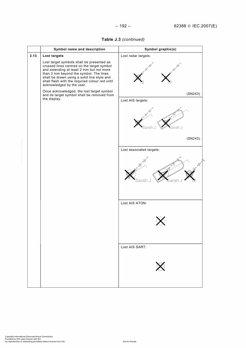
– 192 – 62388 © IEC:2007(E)
Table J.3 (continued)
Symbol name and description Symbol graphic(s)
Lost radar targets:
18 18
(SN243)
Lost AIS targets:
Sarah J Sarah J
(SN243)
3.13 Lost targets
Lost target symbols shall be presented as crossed lines centred on the target symbol and extending at least 2 mm but not more than 3 mm beyond the symbol. The lines shall be drawn using a solid line style and shall flash with the required colour red until acknowledged by the user.
Once acknowledged, the lost target symbol and its target symbol shall be removed from the display.
Lost associated targets:
Sarah J Sarah J 18
Lost AIS ATON:
Lost AIS SART:
Copyright International Electrotechnical Commission Provided by IHS under license with IEC
Not for ResaleNo reproduction or networking permitted without license from IHS
--`,,```,,,,````-`-`,,`,,`,`,,`---
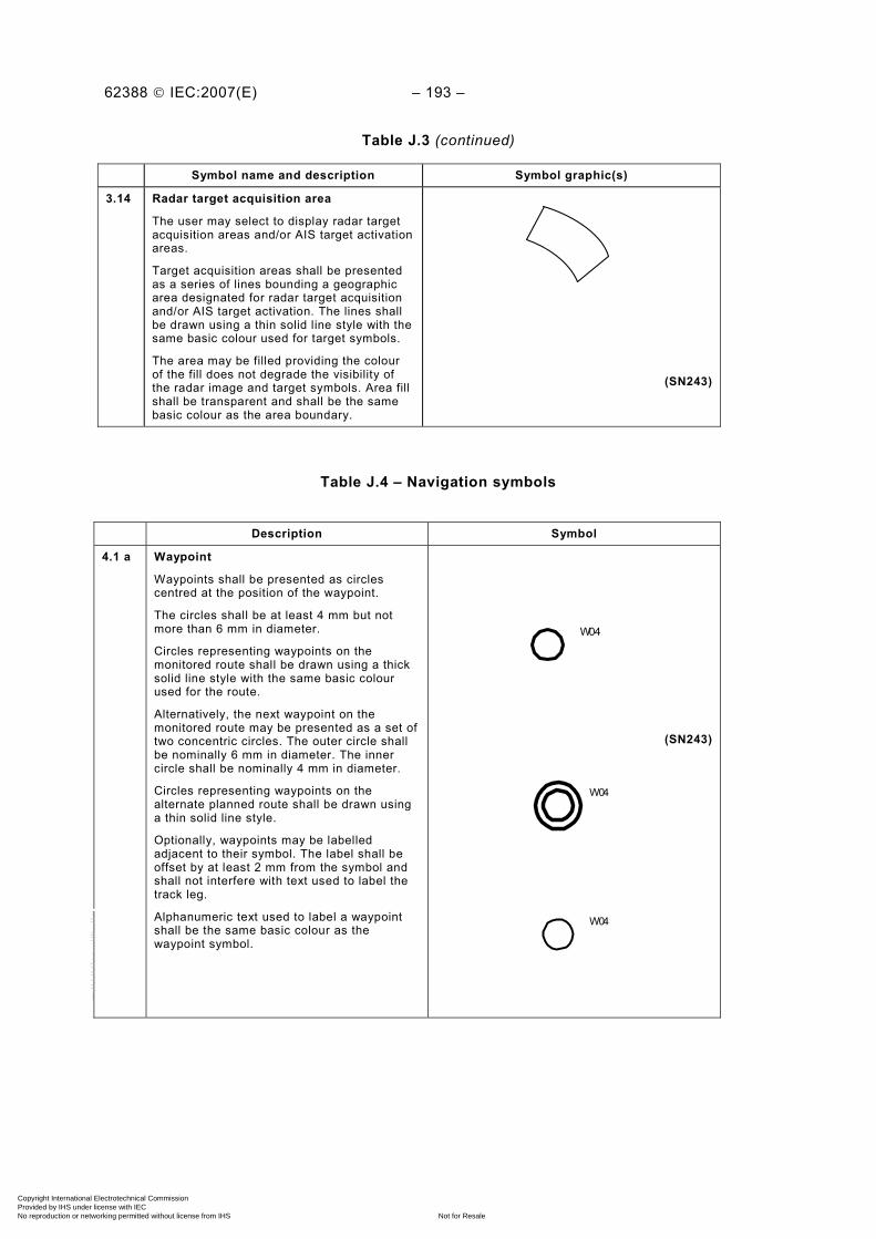
62388 © IEC:2007(E) – 193 –
Table J.3 (continued)
Symbol name and description Symbol graphic(s)
3.14 Radar target acquisition area
The user may select to display radar target acquisition areas and/or AIS target activation areas.
Target acquisition areas shall be presented as a series of lines bounding a geographic area designated for radar target acquisition and/or AIS target activation. The lines shall be drawn using a thin solid line style with the same basic colour used for target symbols.
The area may be filled providing the colour of the fill does not degrade the visibility of the radar image and target symbols. Area fill shall be transparent and shall be the same basic colour as the area boundary.
(SN243)
Table J.4 – Navigation symbols
Description Symbol
4.1 a Waypoint
Waypoints shall be presented as circles centred at the position of the waypoint.
The circles shall be at least 4 mm but not more than 6 mm in diameter.
Circles representing waypoints on the monitored route shall be drawn using a thick solid line style with the same basic colour used for the route.
Alternatively, the next waypoint on the monitored route may be presented as a set of two concentric circles. The outer circle shall be nominally 6 mm in diameter. The inner circle shall be nominally 4 mm in diameter.
Circles representing waypoints on the alternate planned route shall be drawn using a thin solid line style.
Optionally, waypoints may be labelled adjacent to their symbol. The label shall be offset by at least 2 mm from the symbol and shall not interfere with text used to label the track leg.
Alphanumeric text used to label a waypoint shall be the same basic colour as the waypoint symbol.
W04
(SN243)
W04
W04
Copyright International Electrotechnical Commission Provided by IHS under license with IEC
Not for ResaleNo reproduction or networking permitted without license from IHS
--`,,```,,,,````-`-`,,`,,`,`,,`---
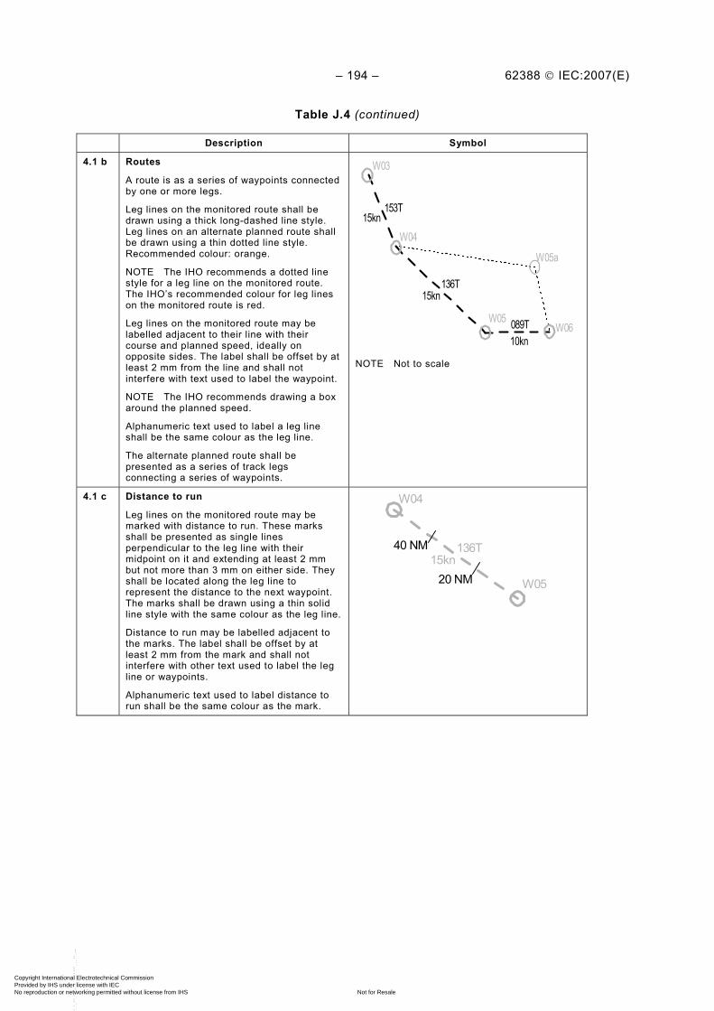
– 194 – 62388 © IEC:2007(E)
Table J.4 (continued)
Description Symbol
4.1 b Routes
A route is as a series of waypoints connected by one or more legs.
Leg lines on the monitored route shall be drawn using a thick long-dashed line style. Leg lines on an alternate planned route shall be drawn using a thin dotted line style. Recommended colour: orange.
NOTE The IHO recommends a dotted line style for a leg line on the monitored route. The IHO’s recommended colour for leg lines on the monitored route is red.
Leg lines on the monitored route may be labelled adjacent to their line with their course and planned speed, ideally on opposite sides. The label shall be offset by at least 2 mm from the line and shall not interfere with text used to label the waypoint.
NOTE The IHO recommends drawing a box around the planned speed.
Alphanumeric text used to label a leg line shall be the same colour as the leg line.
The alternate planned route shall be presented as a series of track legs connecting a series of waypoints.
W04
W03
153T15kn
W05a
136T15kn
W05W06089T
10kn NOTE Not to scale
4.1 c Distance to run
Leg lines on the monitored route may be marked with distance to run. These marks shall be presented as single lines perpendicular to the leg line with their midpoint on it and extending at least 2 mm but not more than 3 mm on either side. They shall be located along the leg line to represent the distance to the next waypoint. The marks shall be drawn using a thin solid line style with the same colour as the leg line.
Distance to run may be labelled adjacent to the marks. The label shall be offset by at least 2 mm from the mark and shall not interfere with other text used to label the leg line or waypoints.
Alphanumeric text used to label distance to run shall be the same colour as the mark.
W04
W05
136T15kn
20 NM
40 NM
Copyright International Electrotechnical Commission Provided by IHS under license with IEC
Not for ResaleNo reproduction or networking permitted without license from IHS
--`,,```,,,,````-`-`,,`,,`,`,,`---

62388 © IEC:2007(E) – 195 –
Table J.4 (continued)
Description Symbol
4.1 d Planned position
Optionally, track legs may be marked with a planned position.
These marks shall be presented as single lines perpendicular to the track leg with their midpoint on the line and extending at least 2 mm but not more than 3 mm on either side. They shall be located along the track leg to represent the distance from the previous waypoint. The marks shall be drawn using a thin solid line style.
Planned position may be labelled adjacent to the mark with the date and time of planned arrival. The label shall be offset by at least 2 mm from the mark and shall not interfere with other labels.
Alphanumeric text used to label planned position shall be the same basic colour as the mark.
W04
W05
136T15kn
20 NM
40 NM
1115/20Jan
4.1 e Visual limit of lights
Leg lines on the monitored route may be marked with the visual limits of lights (i.e. rising/dipping range).
The visual limit shall be presented as an arc centred on the light and extending across the track leg at least 10 mm on either side. The arc shall be drawn using a thin solid line with the same basic colour as the leg line.
The visual limit may be labelled adjacent to the arc with the rising/dipping range and information about the light.
Alphanumeric text used to label visual limits shall be the same basic colour as the arc.
W04
W05
136T15kn
20 NM
40 NM
1115/20Jan
Ushant LtFI(2) W 10s
(24NM)
4.1 f Wheel-over position
Track leg lines on the monitored route may be marked with a wheel-over position. The wheel-over position shall be presented as single line centred on the current leg line, parallel to the next leg line and extending at least 5 mm on either side of the current leg line. The line shall be drawn using a thin solid line with the same colour as the leg line.
The wheel-over position may be labelled adjacent to the line with the planned rudder angle and time of wheel-over. Alphanumeric text used to label wheel-over position shall be the same basic colour as the wheel-over position line.
Ushant LtFI(2) W 10s
(24NM)
W05
136T15kn
121315 deg
1115/20Jan
Copyright International Electrotechnical Commission Provided by IHS under license with IEC
Not for ResaleNo reproduction or networking permitted without license from IHS
--`,,```,,,,````-`-`,,`,,`,`,,`---

– 196 – 62388 © IEC:2007(E)
Table J.4 (continued)
Description Symbol
4.2 Plotted position
A plotted position (Fix, EP, and DR) shall be presented as a circle with crossed lines centred at the position. The circle shall be 5 mm in diameter. The length of the crossed lines shall be the diameter of the circle.
The circle and crossed lines shall be drawn using a thin solid line style.
The position shall be labelled with time and an indication of its source. If the position is an estimated position, it shall also be labelled with the letters “EP”. If the position is a dead reckoned position, it shall also be labelled with the letters “DR”.
Alphanumeric text used to label the position shall be the same basic colour as the symbol.
1115
GNSS
1115
EP GNSS
1115
DR GNSS
4.3 Line of position
A line of position (LOP) shall be presented as a single line originating from a charted object and extending towards own ship. The bearing of the LOP shall be referenced to the CCRP.
The LOP shall be drawn using a thin solid line style.
The LOP shall be labelled with time. If the LOP is transferred, it may also be labelled with the letters “TPL” for transferred position line.
Alphanumeric text used to label LOP shall be the same basic colour as the line.
0705
0705TPL
NOTE Examples show the default symbol for a water tower
Copyright International Electrotechnical Commission Provided by IHS under license with IEC
Not for ResaleNo reproduction or networking permitted without license from IHS
--`,,```,,,,````-`-`,,`,,`,`,,`---
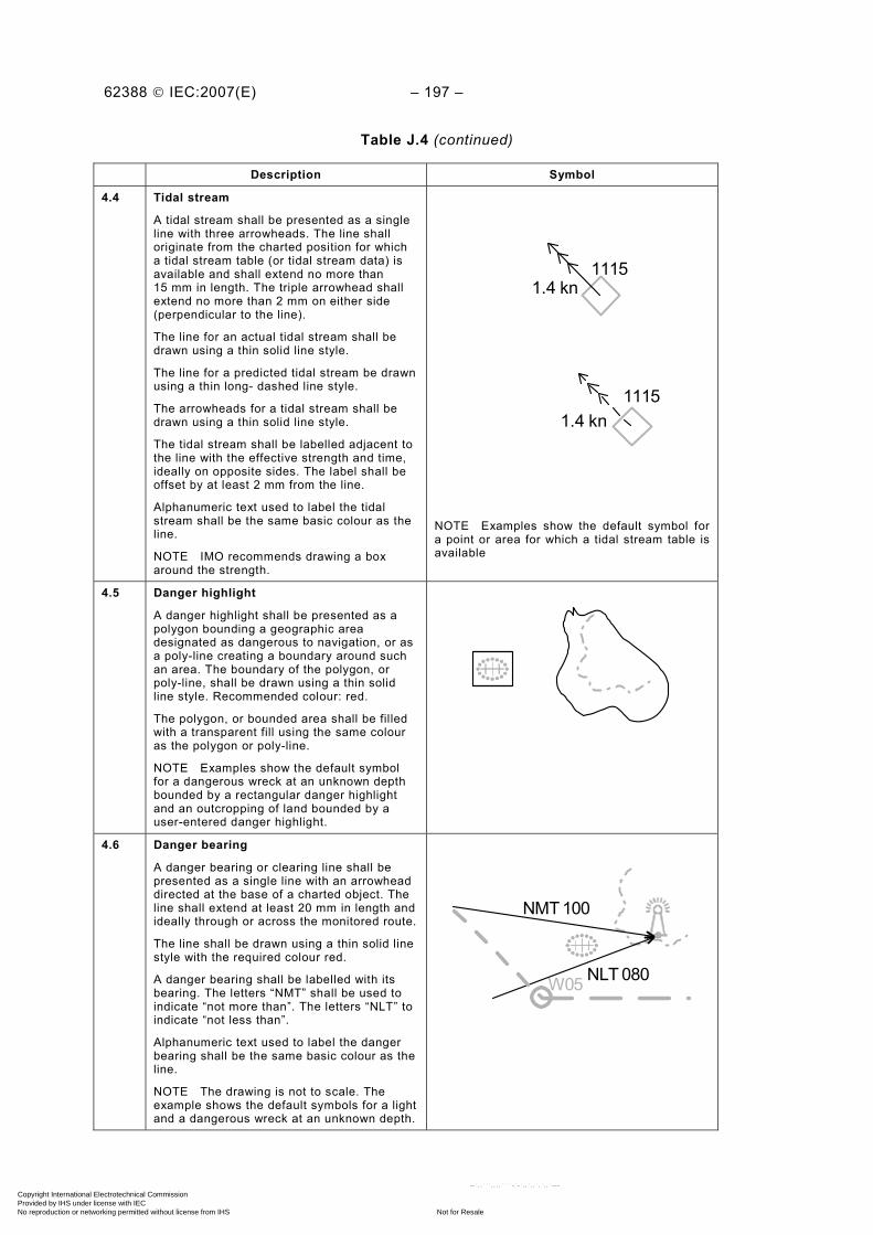
62388 © IEC:2007(E) – 197 –
Table J.4 (continued)
Description Symbol
4.4 Tidal stream
A tidal stream shall be presented as a single line with three arrowheads. The line shall originate from the charted position for which a tidal stream table (or tidal stream data) is available and shall extend no more than 15 mm in length. The triple arrowhead shall extend no more than 2 mm on either side (perpendicular to the line).
The line for an actual tidal stream shall be drawn using a thin solid line style.
The line for a predicted tidal stream be drawn using a thin long- dashed line style.
The arrowheads for a tidal stream shall be drawn using a thin solid line style.
The tidal stream shall be labelled adjacent to the line with the effective strength and time, ideally on opposite sides. The label shall be offset by at least 2 mm from the line.
Alphanumeric text used to label the tidal stream shall be the same basic colour as the line.
NOTE IMO recommends drawing a box around the strength.
11151.4 kn
11151.4 kn
NOTE Examples show the default symbol for a point or area for which a tidal stream table is available
4.5 Danger highlight
A danger highlight shall be presented as a polygon bounding a geographic area designated as dangerous to navigation, or as a poly-line creating a boundary around such an area. The boundary of the polygon, or poly-line, shall be drawn using a thin solid line style. Recommended colour: red.
The polygon, or bounded area shall be filled with a transparent fill using the same colour as the polygon or poly-line.
NOTE Examples show the default symbol for a dangerous wreck at an unknown depth bounded by a rectangular danger highlight and an outcropping of land bounded by a user-entered danger highlight.
4.6 Danger bearing
A danger bearing or clearing line shall be presented as a single line with an arrowhead directed at the base of a charted object. The line shall extend at least 20 mm in length and ideally through or across the monitored route.
The line shall be drawn using a thin solid line style with the required colour red.
A danger bearing shall be labelled with its bearing. The letters “NMT” shall be used to indicate “not more than”. The letters “NLT” to indicate “not less than”.
Alphanumeric text used to label the danger bearing shall be the same basic colour as the line.
NOTE The drawing is not to scale. The example shows the default symbols for a light and a dangerous wreck at an unknown depth.
NMT 100
NLT 080W05
Copyright International Electrotechnical Commission Provided by IHS under license with IEC
Not for ResaleNo reproduction or networking permitted without license from IHS
--`,,```,,,,````-`-`,,`,,`,`,,`---
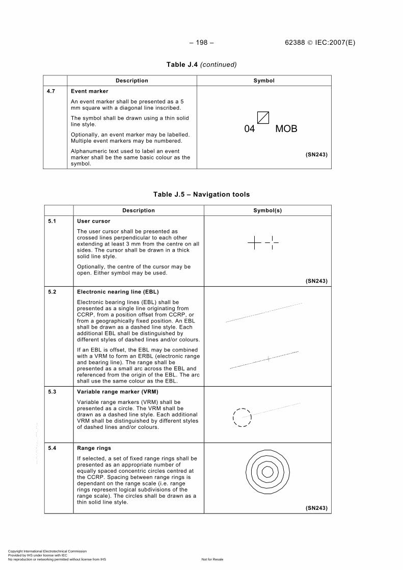
– 198 – 62388 © IEC:2007(E)
Table J.4 (continued)
Description Symbol
4.7 Event marker
An event marker shall be presented as a 5 mm square with a diagonal line inscribed.
The symbol shall be drawn using a thin solid line style.
Optionally, an event marker may be labelled. Multiple event markers may be numbered.
Alphanumeric text used to label an event marker shall be the same basic colour as the symbol.
04 MOB
(SN243)
Table J.5 – Navigation tools
Description Symbol(s)
5.1 User cursor
The user cursor shall be presented as crossed lines perpendicular to each other extending at least 3 mm from the centre on all sides. The cursor shall be drawn in a thick solid line style.
Optionally, the centre of the cursor may be open. Either symbol may be used.
(SN243)
5.2 Electronic nearing line (EBL)
Electronic bearing lines (EBL) shall be presented as a single line originating from CCRP, from a position offset from CCRP, or from a geographically fixed position. An EBL shall be drawn as a dashed line style. Each additional EBL shall be distinguished by different styles of dashed lines and/or colours.
If an EBL is offset, the EBL may be combined with a VRM to form an ERBL (electronic range and bearing line). The range shall be presented as a small arc across the EBL and referenced from the origin of the EBL. The arc shall use the same colour as the EBL.
5.3 Variable range marker (VRM)
Variable range markers (VRM) shall be presented as a circle. The VRM shall be drawn as a dashed line style. Each additional VRM shall be distinguished by different styles of dashed lines and/or colours.
5.4 Range rings
If selected, a set of fixed range rings shall be presented as an appropriate number of equally spaced concentric circles centred at the CCRP. Spacing between range rings is dependant on the range scale (i.e. range rings represent logical subdivisions of the range scale). The circles shall be drawn as a thin solid line style.
(SN243)
Copyright International Electrotechnical Commission Provided by IHS under license with IEC
Not for ResaleNo reproduction or networking permitted without license from IHS
--`,,```,,,,````-`-`,,`,,`,`,,`---

62388 © IEC:2007(E) – 199 –
Table J.5 (continued)
Description Symbol(s)
5.5 (parallel) Index lines
Parallel index lines shall be presented as a series of lines aligned to a set bearing, and spaced at a series of beam ranges (for example at the range ring spacing).
No line style is specified for (parallel) index lines however, they shall be distinguishable from each other and from EBLs.
Index lines set at other bearings may be used.
A series of index lines at other positions may be used.
Table J.6 – Other symbols
Description Symbol(s)
6.1 Trial manoeuvre
When a trial manoeuvre function is enabled, it shall be indicated by the presentation of a large letter “T” in a conspicuous location in the operational display area.
T
(SN243)
6.2 Simulation mode
When a simulation mode is enabled, it shall be indicated by the presentation of a large letter “S” in a conspicuous location in the operational display area.
S
(SN243)
6.3 Radar test target
When an internally generated test target is enabled, it shall be indicated by the presentation of the large letter “X” adjacent to the target with the basic colour used for the target symbol.
In addition, a bold “X” shall be shown in a conspicuous location in the operational display area.
X
– 200 – 62388 © IEC:2007(E)
Annex K (normative)
Colour calibration for chart radar
K.1 Requirement
The colour definition and calibration requirements shall be applicable to a chart radar.
If the display equipment supports the display of charted information within the operational display area then the colours and luminance used to display alphanumeric data, text, symbols and other graphical information in the operational display area for chart features shall comply with or be based upon the 64 colour tokens defined in the IHO S-52 colour tables for each ambient light condition likely to be experienced on the bridge of a ship (day, dusk and night). Non-chart features shall not be restricted by IHO requirements.
The difference between any two colours displayed shall be not less than 10 ∆E* units, except for those pairs defined to have a tabular ΔE* less than 20 (see IHO S-52, Appendix 2, 5.2.3.1 and IHO S-52, Appendix 2, Annex B, 4.5).
The difference between the colour displayed and the colour defined in IHO S-52, Appendix 2 shall be not greater than 16 ∆C* units. If a monitor is tested independent of the video source to be used, then the difference shall be not greater than 8 ∆C* units (see IHO S-52, Appendix 2, 5.2.3.1.)
The luminance of the colours displayed shall be within 20 % of the value specified in IHO S-52 Appendix 2. The luminance value for the colour black using the “day” colour table shall be not greater than 0,52 cd/m² (see IHO S-52 Appendix 2, 5.2.3.1).
NOTE The colour tables are provided in the IHO ECDIS Presentation Library. The IHO ECDIS Presentation Library contains colour differentiation test diagrams to enable the user to determine whether it is possible to discriminate important features by colour (see IHO S-52, Appendix 2, 4.1.5 and IEC 61174, 6.7.3).
Visual discrimination between symbols and against the background provided in the operational display area depends on differences in colour. CIE Publication 15, defines the following units for colour difference in terms of chrominance and luminance:
• ΔE* as a measure of the overall discrimination including both chrominance and luminance differences;
• ΔC* as a measure of the discrimination in chrominance alone.
The colours specified for the symbols used to present chart features are identified by the set of colour tokens specified in the IHO S-52 Presentation Library using the CIE 1931 colour coordinate system (x, y and L), which specify chrominance and luminance. (See CIE 15.) Tolerances for conversion from CIE 1931 colour coordinates to actual RGB values for individual display equipment and measured performance are defined by three terms:
• ΔE* between the colour coordinates resulting from the RGB values calculated for each token and the other colours of the same colour table for each ambient light condition (day, dusk and night) to determine whether the colours within each RGB colour table remain discriminably separate (i.e. that the relative distinctions between colours have been maintained);
• ΔC* between the defined colour coordinates and the coordinates resulting from the RGB values calculated for each token within each colour table for each ambient light condition (day, dusk and night), and the colour coordinates; to determine whether the actual RGB colours resulting from the conversion remain reasonably close to the defined CIE 1931 colours (i.e. that the blues stay blue and the greens stay green);
Copyright International Electrotechnical Commission Provided by IHS under license with IEC
Not for ResaleNo reproduction or networking permitted without license from IHS
--`,,```,,,,````-`-`,,`,,`,`,,`---
62388 © IEC:2007(E) – 201 –
• Luminance ratio (Lmeasured/Ldefined) between the defined coordinates of the colour tokens within the colour table for each ambient light condition; day, dusk and night, and the colour coordinates of the calculated RGB values for each colour token; to determine whether the luminance remains within acceptable limits.
ΔE* shall be a minimum of 10 except for colour pairs listed in IHO S-52, Appendix 2, Annex B, 5.5, which, as defined, are very close in colour.
ΔC* shall be a maximum of 16 for display equipment tested as part of the navigational system or equipment (i.e. where the display screen and its source of video are tested together). ΔC* shall be a maximum of 8 for system components that are tested independently of each other (i.e. where the display screen equipment is not tested with the identical video source that it will be installed with aboard ship or where a computer is not tested with the identical display screen that it will be installed with aboard ship).
The luminance ratio shall be within 20 % of the value specified for each colour token within the colour table for each ambient light condition; day, dusk and night, except for the colour black, which shall be a maximum 0,52 cd/m² for the day colour table.
NOTE The day colour table specified in IHO ECDIS Presentation Library Ed. 3.3 uses a white background that may not support readability under all light conditions and may be a risk to safety of navigation for some navigational systems and equipment including radar. Readability may be achieved by using the black background in the dusk or night colour tables specified in IHO ECDIS Presentation Library Ed. 3.3, or the day black background colour table specified in IHO ECDIS Presentation Library Ed. 3.2, and adjusting brightness and contrast, if provided, for use under all light conditions.
K.2 Method of test and required results
Colour table calibration verification measurements shall be carried out in a dark room. Manufacturers may choose between two different methods of colour calibration. The first method is for test of a monitor and a video source intended to be installed together as an integrated system. The second method is for test of a monitor independent of the video source/computer with which it will be installed or, similarly, a video source tested independently of a monitor. For independent test of monitors, the manufacturer shall provide a reference computer. For independent test of computers, the manufacturer shall provide a reference monitor. The test shall be performed as follows:
a) confirm by analytical evaluation for each colour table that the difference between the calculated RGB values for any two colours in the table are at least 10 ∆E* units, except for those pairs defined to have a tabular ΔE* less than 20. (See IHO S-52, Appendix 2, 5.2.3.1 and IHO S-52, Appendix 2, Annex B, 5.5.).Confirm by measurement and analytical evaluation that the results of the colour calibration conversion of each specified colour (x, y, L) for each colour table into RGB values for an individual monitor are within the tolerance (procedure described in IHO S-52, Annex B, section 4);
b) display a completely black image on the screen provided by the manufacturer. Confirm by measurement perpendicular to the centre of the screen that the luminance is as required (less or equal to 0,52 cd/m²);
c) for the day colour table, select a screen provided by the manufacturer which has a box of CHWHT (brightest white) on a black background. The box size shall be at least 5 cm per side but not more than 25 % of the total screen area. Confirm by measurement perpendicular to the centre of the screen that the level of CHWHT is within the tolerances of ∆C* (∆C* < 16 for integrated units, ∆C* < 8 for independent test) and ∆L* (is within 20 % of its specified value);
d) repeat the test for CHMGF (brightest magenta), CHYLW (brightest yellow) and BKAJ2 (darkest grey) from the day colour table;
e) repeat the test for CHWHT, CHMGF, CHYLW and BKAJ2 from the dusk colour table; f) repeat the test for CHWHT, CHMGF, CHYLW and BKAJ2 from the night colour table;
Copyright International Electrotechnical Commission Provided by IHS under license with IEC
Not for ResaleNo reproduction or networking permitted without license from IHS
--`,,```,,,,````-`-`,,`,,`,`,,`---

– 202 – 62388 © IEC:2007(E)
g) colour table calibration verification observations shall be carried out as follows. The user’s manual brightness control and contrast control, if provided, shall be set to their calibration reference settings; while the display is off, adjust the ambient light level reflected from a white paper positioned on the display screen to the appropriate ambient values specified in Table 9. For each colour table provided, under the appropriate ambient light condition, display the colour differentiation test diagram (Refer to IHO S-52, Appendix 2, Annex A, Part 3, 4.1). Confirm by observation that: – each foreground stripe is clearly distinguished from its background; – the foreground stripes representing yellow, orange, magenta, green, blue and grey
may be clearly identified; h) under each of the ambient light conditions defined above, display the black-adjust
boxes available from ECDIS Chart 1 (refer to chart AA5C1ABO of ECDIS Chart 1). Select each table in turn and confirm by observation that the ECDIS colour token BKAJ02 (dark grey) is clearly distinguished against a black background (BKAJ01);
i) confirm by observation that the procedure for on-board use of the colour differentiation test diagrams is defined in the equipment manual and that the differentiation diagrams are available on demand for the user in a non-operative mode;
j) confirm by document inspection that means are provided to return the display to the calibrated brightness and contrast settings for each ambient light condition defined above;
k) confirm by observation that each of the mandatory colour tables provided in the presentation library may be selected by the user.
NOTE The person conducting the test should have passed the minimum colour vision and acuity tests required for users by IMO STCW Code, Part B, Table B-1/9 and have adapted to night viewing for 10 min before checking the night display.
___________
Copyright International Electrotechnical Commission Provided by IHS under license with IEC
Not for ResaleNo reproduction or networking permitted without license from IHS
--`,,```,,,,````-`-`,,`,,`,`,,`---

Copyright International Electrotechnical Commission Provided by IHS under license with IEC
Not for ResaleNo reproduction or networking permitted without license from IHS
--`,,```,,,,````-`-`,,`,,`,`,,`---

INTERNATIONAL ELECTROTECHNICAL COMMISSION 3, rue de Varembé P.O. Box 131 CH-1211 Geneva 20 Switzerland Tel: + 41 22 919 02 11 Fax: + 41 22 919 03 00 [email protected] www.iec.ch
Copyright International Electrotechnical Commission Provided by IHS under license with IEC
Not for ResaleNo reproduction or networking permitted without license from IHS
--`,,```,,,,````-`-`,,`,,`,`,,`---