edict nine manual - felt bicycles suspension manual edict nine manual 3 4 4. maintenance overview:...
TRANSCRIPT

Edict Nine Manual
Edict Suspension ManualEdict Nine Manual
1 2
1.2.3.4.5.6.7.
Felt recommends that you start with between 20 and 30 percent sag to get optimal performance from your Felt Edict Nine.
To determine your actual sag you must first slide the travel indicator on the shock absorber (the small “o”-ring on the effective shaft of the shock) upwards until it rests against the larger part of the shock. Then, with both hands on the respective handlebar grips throw a leg over the bike and gently allow your full body weight to compress the suspension. Then, slowly roll off lifting your weight off the bike. When you now look at the shock you will see that the o-ring has moved. The distance between the o-ring and the top body of the shock is the actual shock sag dimension.
For the Edict Nine this measurement should fall between 9mm and 12mm.
Important: Try not to “bounce” or sit up while applying weight to the bike. Doing so can drastically throw off the resulting measurement. If you feel you have made an error, you can easily slide the travel indicator up and start over.
Suggested sag settings should only be used as an initial starting point. In many cases the actual settings that work best for you may be different than what works for others due to riding style, terrain or simply personal preference. We suggest that you experiment with air pressure and damping settings to arrive at “your” desired feel. More sag (less air pressure) for a softer, suppler ride or less sag (more air pressure) for a firmer ride.
WARNING: The bicycle should be considered as a system when setting air pressures. Changing rear shock air pressure will effectively change the bikes geometry, so the fork air pressure/preload should be checked at the same time for correct sag to ensure proper geometry and handling. Failure to do so could adversely affect steering and handling characteristics, resulting in possible loss of control, injury, or even death. Refer to the fork owner’s manual for instructions on setting correct sag, air pressure and damping settings. If you did not receive or misplaced your fork owner’s manual, refer to the manufacturer’s website for details on proper care and maintenance procedures.
Congratulations on purchasing this high quality Felt bicycle. As with all of our bikes and components, our aim is to provide you, the rider, with the best possible product and therefore the best possible riding experience.
Please read this owner’s manual Supplement thoroughly, as its purpose is to help you better understand your bike, set it up correctly, and care for it. If there are any questions that you still have after reading this guide, please contact your Felt authorized dealer, or visit our comprehensive website at feltbicycles.com
Happy Trails! - Felt Bicycles.
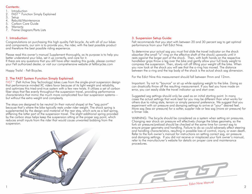
FAST™ (Felt Active Stay Technology) takes cues from the single-pivot suspension design that performance-minded XC riders favor because of its light weight and reliability, and optimizes this tried-and-true system with a few new twists. It utilizes a set of carbon fiber stays that flex evenly throughout the suspension travel, providing performance characteristics that mimic the much more complicated four-bar suspension systems—but without the extra weight and complexity.
The stays are designed to be neutral (in their natural shape) at the “sag point” because that’s where the bike typically rests under rider weight. The shock spring is supplemented by the design and material of the rear stay, which acts as a leaf spring, stiffening the latter part of the suspension travel. The slight additional spring provided by the carbon stays helps keep the suspension sitting at the proper sag point, which reduces small inputs from the rider that would cause unwanted bobbing from the suspension.
IntroductionFAST™ Function Simply ExplainedSetupRebuild/MaintenanceCarbon Care Guide WarrantyFrame Diagram/Parts Lists
Contents:
3. Suspension Setup Guide:1. Introduction:
2. The FAST System Function Simply Explained:

Edict Suspension ManualEdict Nine Manual
3 4
4. Maintenance Overview:While all Felt frames are designed to be strong and durable, a little preventive maintenance will protect your investment and provide endless hours of trail riding fun.
General Maintenance
All bearings used on Felt suspension frames are high quality sealed units. They are designed to provide a long working life; however keeping the bearings clean will extend their useful life.
When cleaning your bike, avoid the use of high pressure water or aerosol spray cleaners. Doing so will drive contaminants into the bearings, causing premature failure. The easiest and simplest way of cleaning the frame is using a bucket of soap and water. This will remove all exterior dirt and grime, preserving the integrity of the bearing seals.
When cleaning the frame it is good practice to periodically check for bearing wear.
1. With the bike in a work stand, clamped by the seat post, remove the rear wheel and deflate the rear shock.
2. Standing behind the frame, lift the rear dropouts, (Move suspension as shown in Fig.1) it should feel smooth, (with light resistance from the carbon rear triangle). Any grinding, notchiness or tight spots may be signs that the bearings need to be overhauled.
3. If the suspension moves smoothly through its travel, check for any side to side movement. Hold the dropouts and try and move them to the left and right. Any looseness may be a sign of loose bearing bolts or worn bearings. (Move suspension as shown in Fig.2)
4. Check the bearing bolts, if any are loose tighten them to the torque spec that is conveniently laser etched into the dust shields. In some instances it may be necessary to reapply a thread locker before you retighten the bearing bolts.
5. If you notice any wear or problems with the bearings your easiest course of action is to replace them. Bearing replacement kits are reasonably inexpensive and the procedure is fairly simple. Bearing kits and complete rebuild kits are available through your local Felt Bicycles retailer.
6. For rear shock maintenance refer to the shock manufacturer’s owner’s manual that was included with your bike. If you did not receive or misplaced your shock owner’s manual, refer to the manufacturer’s website for details on proper care and maintenance procedures.
Fig. 1 Fig. 2

5 6
Bearing Replacement: Master Bearing Tool Kit Diagram:IMPORTANT - Read and thoroughly comprehend these instructions prior to beginning. Doing so will save you time in the long run and help keep your Felt frame running smoothly and safely.
Tools required:
Loctite 242 (Thread Locker) Anti-Seize Lubricant/Compound4mm, 5mm and 6mm Allen (hex) wrenchTorque wrench (Metric) with 5 and 6mm hex bit10mm, 12mm and 15mm open wrenchBearing removal/installation tool kitRubber/plastic faced hammerX-acto knife or dental pickCleaner/degreaserAcetone or similar solventQ-Tip or similar
Frame Disassembly:
1. CLEAN YOUR BIKE!! Even if you clean your bike regularly, clean it again. Dirt and contaminants including oil and grease will affect the reassembly of the frame components and could prevent bearings from seating correctly and could also keep the Loctite from curing.
2. After correctly mounting your bike in a work stand (Remember to NEVER clamp any part of the frame in a repair stand!), remove the wheels, rear derailleur, rear brake caliper, crank set and BB. The fewer components on the frame the easier it will be for you to work on!
3. Loosen each pivot bolt, but do not remove any hardware yet.
4. Deflate the shock, remove the shock mounting bolts and set the shock to the side.
5. Remove the seatstay axle and bolt assemblies that attach the rear triangle to the linkage. Be sure to not lose the Acetyl Thrust Washers that fit between the Links and the Seatstay Yoke.
6. Now remove the bearing axle from the Chainstay Yoke. The rear triangle should be free from the frame. Be careful to not lose any stainless steel spacer washers.
7. Remove the bolts from the shock links. Be careful to catch the Acetyl Thrust Washers between the link and the frame. The shock link plates should now be free from the frame.
Note: Not all tools from the master tool kit will be needed for this model of Felt Bicycle and may not be included in your bike’s tool kit.
A
BD
I
L
O
R
J
M
P
S
K
N
Q
T U V
EF G H
C

7 8
Removing Bearings:
Installing Bearings:
1. To remove the Main Pivot Bearings orient the tool as seen in Fig. 3. Use an Allen wrench and open wrench to draw the bearings out of the Chainstay Yoke.
IMPORTANT - The properties that make Acetone and similar solvents work so well as a cleaner can also harm paint and break down carbon fiber resin. Be very careful where you apply the solvent as it may compromise the integrity of the rear triangle and/or the paint finish of your frame.
(Caution-Eye and Hand protection should ALWAYS be used when handling solvents to avoid contact!)
2. To reassemble the Main Pivot, orient the tools as shown in Fig. 7. Tighten the screw to press the bearing into the Chainstay Yoke. Repeat for both sides.
1. Once all the bearings have been removed, clean the bearing bores using the dental pick or X-acto knife to remove all traces of old bearing seating compound/green loctite. Wipe down the bearing bore with a Q-tip soaked in a small amount of solvent such as acetone. This will remove any last traces of loctite and other contaminants. Don’t get solvent on any other portion of the frame or rear triangle as damage to the paint or carbon resin may occur.
2. To remove the bearings from the Seat Tube orient the tools as seen in Fig. 4. Holding Tool “M” with a 15mm open wrench will prevent the Link Axle from spinning as you tighten the M6 x 35mm bolt (T). This will draw the axle from the frame, bringing one bearing with it. Once the first bearing is removed, repeat this step for the other bearing.
3. Place the links on your bench and assemble the DU bushing removal tools as shown in Fig. 5. Use an Allen wrench and open wrench to draw the DU Bushings out of the back of the links.
4. Disassemble The dropout Pivots as follows:
A) Remove the Chainstays from the seatstays by removing the Dropout Axle at each dropout.
B) Insert the 12mm Split Bearing Puller (tool “W”) into one bearing in the front triangle. You should feel it “snap” into place between the bearing and the internal spacer.
Alloy Model Instructions
of the back of the links.
Fig. 5
Q
O D
C) Assemble the rest of the tools as seen in Fig. 6.
D) As you tighten the bolt the Split Bearing Puller will draw the bearing into the Bearing Receiver (U). Repeat for both bearings in the Left and Right dropouts.
D LH
Fig. 3
Fig. 4
Fig. 6
Fig. 7
B E Q K OI C
H
D
L
F
G IF K T
S C

Edict Suspension ManualEdict Nine Manual
9 10
5. To press fresh DU Bushings into the shock links orient the tools as seen in Fig. 10. The DU Press (M) should center itself inside the DU Bushing. Tighten the bolt until the Flange on the DU Press touches the link. Repeat for both left and right links.
6. To reassemble the Dropout Pivot, orient the tools as shown in Fig. 11. Tighten the screw to press the bearing into the frame. Remember to insert the internal spacer/sleeve before repeating this step for the second dropout pivot bearing.
7. After making sure that all of the hardware is cleaned of any contaminants, discard any damaged bearings, spacers, axles or bolts. You are now ready to re-assemble the frame.
4. To assemble the second bearing in the Seat Tube Pivot, first slip the Link Axle through the bearing you just installed in step 3, then assemble the tools as shown in Fig. 9. Tighten the tool assembly using two 5mm Allen/Hex Wrenches, one in each screw, to draw the second bearing over the axle and into the frame.
3. To install the first new bearing into the Seat Tube Pivot orient the tools as shown in Fig. 8. Tighten the screw to draw the bearing into one side of the frame.
Alloy Model InstructionsAlloy Model Instructions
H
C I
QO
D
CEPRKF
F
KN
A
H F
KN
D
Fig. 8
Fig. 9
Fig. 10
Fig. 11

11 12
(Note: use Anti-Seize Lubricant on all Titanium hardware)
1. Attach the rear triangle to the front triangle at the Main Pivot area. With the stainless steel spacer washers in place between the bearings and the frame, tighten the bearing axle to the torque indicated by the laser etching.
2. Attach the rebuilt shock link plates to the frame, making sure the Acetyl Thrust Washers are in place (placed on the inside, between the bearing and the links). Install the bolts, but leave them loose for now.
3. Attach the seatstays to the upper link. Place an Acetyl Thrust Washer in between the Seatstay ends and the Shock Links. Slip the Seatstay Axles through the DU Bushing in the link and through the Acetyl Thrust Washer, into the pocket in the Seatstay Yoke. Install the M6 x 20mm long Bolts through the axles and into the press-in axle nuts. Tighten to the torque specified on the links, or 11Nm.
4. Once the Shock Links are tightened to the Seatstay Yoke, tighten the Shock Link bolts, installed in step 2, to the torque specified on the links, or 11Nm.
5. Re-install the shock, remembering that the upper and lower bolts may be different lengths. Once the bolts are assembled in their proper locations they will need to be tightened to the torque specified on the shock link.
6. Once complete, re-inflate the shock to your preferred pressure and/or recommended sag (see Section 3 of this manual for proper sag settings).
7. Reinstall any parts you removed initially to access your suspension components.
8. Go Ride…
9. All pivot and mounting bolts should be re-checked for correct tightness/torque after the first ride and periodically ever few rides after that.
Frame Reassembly:Alloy Model Instructions
Removing Bearings:
1. To remove the Main Pivot Bearings, insert the 15mm Split Bearing Puller (tool “V”) into one bearing in the front triangle. You should feel it “snap” into place between the bearing and the internal spacer. Then orient the rest of the tools as seen in Fig. 3. Use an Allen wrench and open wrench to draw the bearings out of the frame. Repeat this for the other side.
2. To remove the bearings from the Seat Tube orient the tools as seen in Fig. 4. Holding Tool “M” with a 15mm open wrench will prevent the Link Axle from spinning as you tighten the M6 x 35mm bolt (T). This will draw the axle from the frame, bringing one bearing with it. Once the first bearing is removed, repeat this step for the other bearing.
3. Place the links on your bench and assemble the DU bushing removal tools as shown in Fig. 5. Use an Allen wrench and open wrench to draw the DU Bushings out of the back of the links.
Carbon Fiber Model Instructions
12
the other bearing.
Fig. 4
Fig. 3
Fig. 5
B E Q
Q
K
O
OI C
D
C UJV F
HI

13 14
Installing Bearings:
IMPORTANT - The properties that make Acetone and similar solvents work so well as a cleaner can also harm paint and break down carbon fiber resin. Be very careful where you apply the solvent as it may compromise the integrity of the rear triangle and/or the paint finish of your frame.
(Caution-Eye and Hand protection should ALWAYS be used when handling solvents to avoid contact!)
2. To reassemble the Main Pivot, orient the tools as shown in Fig. 7. Tighten the screw to press the bearing into the frame. Remember to insert the internal spacer/sleeve before repeating this step for the second main pivot bearing.
1. Once all the bearings have been removed, clean the bearing bores using the dental pick or X-acto knife to remove all traces of old bearing seating compound/green loctite. Wipe down the bearing bore with a Q-tip soaked in a small amount of solvent such as acetone. This will remove any last traces of loctite and other contaminants. Don’t get solvent on any other portion of the frame or rear triangle as damage to the paint or carbon resin may occur.
Carbon Fiber Model Instructions
7. After making sure that all of the hardware is cleaned of any contaminants, discard any damaged bearings, spacers, axles or bolts. You are now ready to re-assemble the frame.
5. To press fresh DU Bushings into the shock links orient the tools as seen in Fig. 10. The DU Press (M) should center itself inside the DU Bushing. Tighten the bolt until the Flange on the DU Press touches the link. Repeat for both left and right links.
4. To assemble the second bearing in the Seat Tube Pivot, first slip the Link Axle through the bearing you just installed in step 3, then assemble the tools as shown in Fig. 9. Tighten the tool assembly using two 5mm Allen/Hex Wrenches, one in each screw, to draw the second bearing over the axle and into the frame.
3. To install the first new bearing into the Seat Tube Pivot orient the tools as shown in Fig. 8. Tighten the screw to draw the bearing into one side of the frame.
Carbon Fiber Model Instructions
H M J J MA
HF
ANK
Fig. 7
Fig. 8
Fig. 9
Fig. 10
B I CEPRKF
QO D

Edict Suspension Manual
15 16Edict Nine Manual
(Note: use Anti-Seize Lubricant on all Titanium hardware)
1. Attach the rear triangle to the front triangle at the Main Pivot area. With the stainless steel spacer washers in place between the bearings and the frame, tighten the bearing axle to the torque indicated by the laser etching.
2. Attach the rebuilt shock link plates to the frame, making sure the Acetyl Thrust Washers are in place (placed on the inside, between the bearing and the links). Install the bolts, but leave them loose for now.
3. Attach the seatstays to the upper link. Place an Acetyl Thrust Washer in between the Seatstay ends and the Shock Links. Slip the Seatstay Axles through the DU Bushing in the link and through the Acetyl Thrust Washer, into the pocket in the Seatstay Yoke. Install the M6 x 20mm long Bolts through the axles and into the press-in axle nuts. Tighten to the torque specified on the links, or 11Nm.
4. Once the Shock Links are tightened to the Seatstay Yoke, tighten the Shock Link bolts, installed in step 2, to the torque specified on the links, or 11Nm.
5. Re-install the shock, remembering that the upper and lower bolts may be different lengths. Once the bolts are assembled in their proper locations they will need to be tightened to the torque specified on the shock link.
6. Once complete, re-inflate the shock to your preferred pressure and/or recommended sag (see Section 3 of this manual for proper sag settings).
7. Reinstall any parts you removed initially to access your suspension components.
8. Go Ride…
9. All pivot and mounting bolts should be re-checked for correct tightness/torque after the first ride and periodically ever few rides after that.
Frame Reassembly:
Carbon Fiber Model Instructions
Carbon Care Guide:
This guide contains important information. Please read carefully and store in a safe place.
Warning! Failure to follow these instructions may result in a catastrophic failure of the frame and/or its components while riding, which may result in serious personal injury or death.
Congratulations! The Felt Suspension frame you have chosen is among the finest products available in cycling. The Carbon fiber that is used in the rear triangle of some frames is a very special material that requires particular care during assembly, storage and riding. This short reference guide contains instructions and warnings specific to Felt Suspension frames that use these Carbon rear triangles.
Unlike metal parts, carbon composite parts that have been damaged may not bend, bulge or deform; a damaged part may appear to be normal to a cursory glance. After any high force load, like a crash, or other impact to your bicycle, thoroughly inspect all the parts of your bike, and use the following procedures to inspect carbon composite parts.
• Check for scratches, gouges, or other surface problems.• Check the part for loss of rigidity.• Check the part for delamination.
If you are the slightest bit unsure… If you have any doubts about the integrity of any part of your Felt Bicycle, do not ride the bicycle and contact either Felt Bicycles directly or your local Felt Bicycles autho-rized dealer for more information or answers to your questions.
Be very careful when handling carbon fiber parts that are suspected of damage. When a composite part is damaged, there is a possibility that individual fibers may be exposed. Carbon fibers are thinner than a human hair, but quite stiff. If the point of one of these fibers is pressed against your skin, it could pierce your skin like a needle.
Warning! A damaged carbon fiber part can fail suddenly, causing serious injury or death. Inspect a carbon fiber bicycle, or parts, for damage frequently. If you suspect a carbon fiber part is damaged, replace the part before riding or take the bike to your dealer for service.
Warning! Do not clamp to, modify or otherwise alter the frame’s Carbon Fiber rear triangle. As well as voiding your warranty it may impair the structural integrity of the frame. Failure to follow this warning may result in serious personal injury or death.
Please visit feltbicycles.com for the latest technical information on our proprietary technology.

Edict Suspension ManualEdict Nine Manual
17 18Edict Nine Manual
17
Edict Nine Alloy Series Parts Illustration
Edict Nine Alloy Series Parts List: QTY / BikeDerailleur hangerDU1310 (13mm ID x 10mm Lg.)6801-2RS MAX Bearing 12x21x5M6x40 SHCSM6x20 SHCSAcetyl Thrust WasherLink AxleSeatstay Pivot AxleO-RingM4x12 Socket Head Cap ScrewBearing Spacer - Main PivotMain Pivot Bolt w/ 22mm capMain Pivot Nut w/22mm cap608-2RSMAX Bearing 8x22x7M6x35 SHCSDropout Pivot ScrewDropout Pivot Outer Spacer Dropout Pivot Inner Spacer
123456789171819202122232425
126144124121121242
18
18
21
21
20
19
6
6
22
6
6

Edict Suspension ManualEdict Nine Manual
19 20
Edict Nine Carbon Series Parts Illustration
Edict Nine Carbon Series Parts List QTY / BikeDerailleur hangerDU1310 (13mm ID x 10mm Lg.)6801-2RS MAX Bearing 12x21x5M6x40 SHCSM6x20 SHCSAcetyl Thrust WasherLink AxleSeatstay Pivot AxleO-RingM4x10 Flat Head Cap ScrewBearing Spacer - Main PivotMain Pivot BoltMain Pivot Collet Cone3802-2RSMAX Bearing 15x24x7M8x45 Custom SHCSInternal Main Pivot Spacer
12345678910111213141516
1221441221211211
12
9
9
13
11
16
14
11
14
6
6
6
6

Felt Racing, LLC12 Chrysler
Irvine, CA 92618
www.feltbicycles.com
Industriestr. 39 26188 Edewecht Germany