edge.rit.eduedge.rit.edu/content/p15571/public/final documents... · web viewcheck if hall signals...
TRANSCRIPT

P15571 Manual
Electrical Hardware User Guide
Sun Tracker will be referred as the whole system which consists of software, electrical and mechanical subsystems.
Warning
Never set 100% Duty Cycle for motor in GUI; motors will wear off more quickly and possibly fire in the case of software failure. This feature is left enabled; occasionally, setting 100% duty cycle allows to run the motor to the position desired quickly in desperate circumstances such as weather condition, manual tracking. 50% duty cycle is recommended for both motors.
Do not modify live circuit; use kill switch and unplug power cord before servicing Sun Tracker.
Emergency
For emergency, use kill switch, located in the PC box, to stop the motors immediately.
Wiring
For rewiring purpose, turn of motor shield by pressing the kill switch and AC power.
Semi-annually/Annually maintenance
Tighten screws on screw terminals.
Check for corrosion on the wires and connectors and if so, turn off the system and replace them immediately.
Necessary Tools for Setup and Debug
Small screw drivers Wire stripperMultimeter Soldering kitOscilloscope
Hall Sensors
1. Hall Signal Count Oscillating1. Make sure hall sensors are provided power (5V and GND at the white screw
terminal).2. Check if hall signals are present at the end of the wires with the oscilloscope.3. Check if hall signals are coming out of Hall Signal Processing PCB.4. Check if Arduino is generating clock at Digital Pin 5.
1

P15571 Manual
2. Hall Signal Count Increment/Decrement Wrong1. Swap Hall A and B signals
Hall Signal Processing PCB (HSP PCB)
See the figure below for wiring connections on hall signals and reference limit switch.
Problem Encountered
Pre-crimped wires are very fragile. After multiple reworks on wires due to changes in location of the boxes, pre-crimped wires had an issue. If wires are not carefully unplugged from PCB by holding on the connector instead of wire, the wires were damaged and lost contact to the crimps. As a result, the hall signals were not seen at the end of the cable on the oscilloscope.
2

P15571 Manual
Motor Shield
Connect linear actuator and slewing motor + and - according to the picture below.
Limit Switches and Diodes
360-Degree Limit Switches and DiodesTwo limit switches are mounted on the slewing drive plate to prevent rotation of more than 360
degree and effectively wire will be protected in the case of software failure. Also, two power diodes are placed in parallel to the switches to stop the rotation in clockwise direction and only allow counterclockwise rotation and vice versa. Both diodes are located in the receiver box instead of PC box to reduce the overall motor wire length.
3

P15571 Manual
360-Degree Limit Switch Placed in Slewing Drive Motor - Line (for reference only)
Reverse Limit Switch and DiodeOne limit switch is mounted to the declination bracket for linear actuator. When linear actuator
retracts, the limit switch will prevent over-retraction when the limit switch is pressed.
Setup ChecklistTo confirm the functionality of limit switches and diodes, run the motor in clockwise direction.
1. Press the counterclockwise limit switch (closer to the dome) and confirm that slewing drive stops running.
2. Press the clockwise limit switch and confirm that the motor does not stop running. 3. Do the above procedure in the same manner for testing clockwise limit switch.4. For linear actuator, retract and press the limit switch which will stop linear actuator from running.
4

P15571 Manual
Problem Encountered
Reverse limit switch diode confirmed to be blowed with a multimeter after testing the limit switch and diode during setup. The likelihood of the cause is reverse saturation current of the diode. The motor are started slowly by incrementing PWM. However, there is no control on motor stop. Sudden stop can cause inductive current spike to be blocked by the diode when the limit switch is pressed. This issue is only discovered after the final installation at Ionia. Current method is to replace the diode.
Power Check
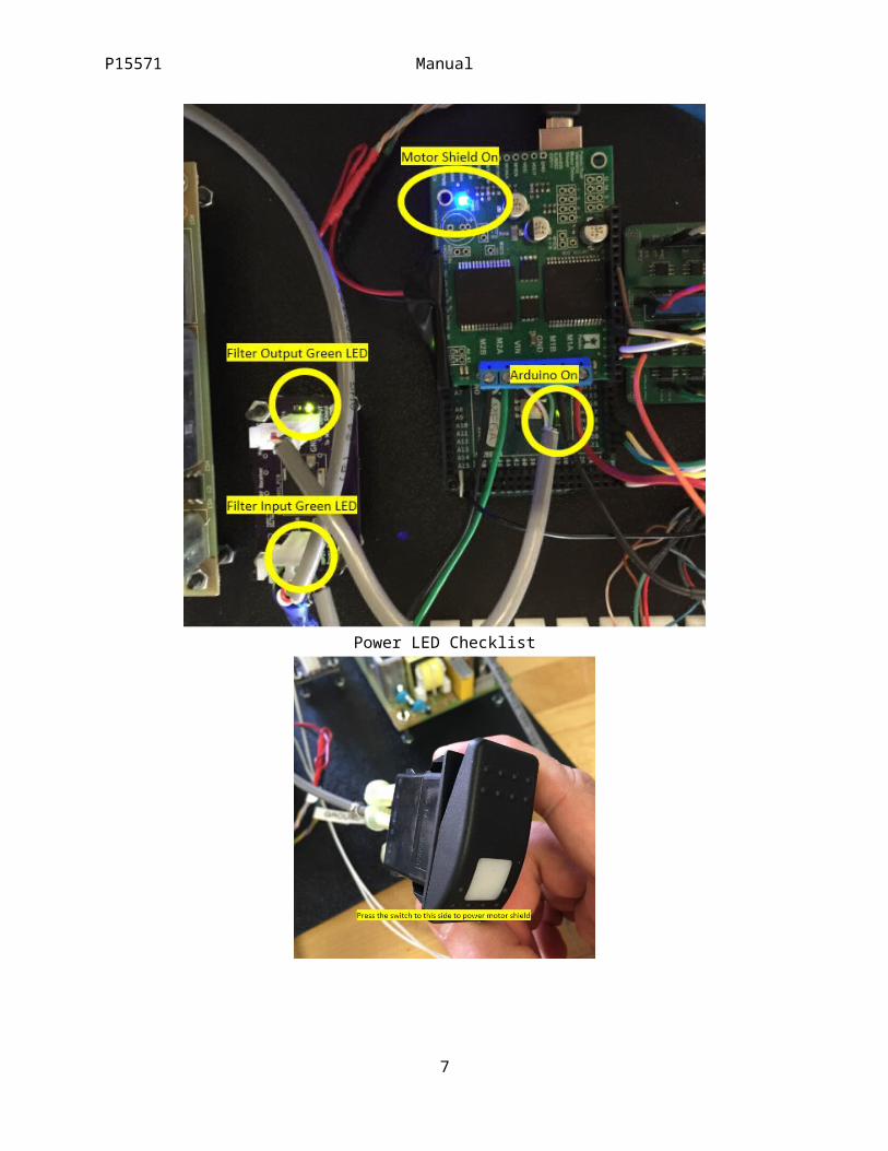
During setup, the motor shield must be powered on.
Motor Not Runninga. Check Kill Switchb. Check LEDs on motor shield (blue) and 12V Filter PCB (2 green leds)c. Check for the loose wire (from 12V Filter PCB to motor shield)
Power LED Checklist
5

P15571 Manual
6
P15571 Manual
Problem Encountered
12V Filtered PCB has wire-to-board connector with crimps. The crimp can cause power loss issue if the wires are improperly crimped using wrong crimp tool or by a person. The problem is fixed by remaking the wires carefully.
White Screw Terminals for 5V and GND
White screw terminal shown in the figure below is used to provide 5V and ground from Arduino to hall sensors from linear actuator and slewing drive and accelerometer.
Grounding the Shield
One of the white screw terminals is used to connect earth ground from 12V power supply chassis to the shield. See the picture above on the right.
Pinouts
In the case of rewiring, reference to this table to maintain the original pinouts. Pinout Table
Name Pin Origin Destination
LA Hall A Digital Pin 3 Linear Actuator HSP PCB
LA Hall B Digital Pin 2 Linear Actuator HSP PCB
SD Hall A Digital Pin 18 Slewing Drive HSP PCB
SD Hall B Digital Pin 19 Slewing Drive HSP PCB
7

P15571 Manual
M1INA Digital Pin 11 Motor Shield Motor Shield
Accel SDA Digital Pin 20 (SDA) Accelerometer Arduino
Accel SCL Digital Pin 21 (SCL) Accelerometer Arduino
Temp+RH Vout Digital Pin 23 Temp + RH Arduino
Ref Limit Switch Digital Pin 31 Ref Limit Switch Arduino
Arduino Clock Digital Pin 5 Arduino HSP PCB
Remapping the Motor Shield
Due to limited number of interrupt pins, one of the motor shield pins is remapped. One of the pins used by the motor shield has the interrupt capability which is needed counting for hall signals. Jumper wire is used to remap from Arduino Digital Pin 2 to Digital Pin 11. In addition, the pin on the female header of motor shield which is inserted into Digital Pin 2 is cut off. The pin used by the motor shield is redefined in the code.
Remapping Pin on the Hardware
8

P15571 Manual
Remapping Code
Waterproof Connectors
There are a total of 4 connectors, three 10-pole connectors and one 7-pole connector. These connectors are color-coded as shown in the figure below.
Connectors Plugged In
9

P15571 Manual
Receptacle Connectors on Receiver BoxIn the case of connector unplugged, make sure to use the cap to seal off.
Waterproof Caps (Box Upside Down)
10