edge gateway niot-e-tib100-gb-re - hilscher.com › fileadmin › cms_upload › en... · passive...
TRANSCRIPT

User manual
Edge Gateway NIOT-E-TIB100-GB-REPassive Operating Mode
V1.1.1
Hilscher Gesellschaft für Systemautomation mbHwww.hilscher.com
DOC180202UM01EN | Revision 1 | English | 2018-04 | Released | Public

Table of contents 2/145
Table of contents1 Introduction .............................................................................................................................. 4
1.1 About this document ........................................................................................................ 41.2 List of revisions ................................................................................................................ 4
2 Passive process data acquisition with the Edge Gateway .................................................. 52.1 Introduction ...................................................................................................................... 5
2.1.1 Comparison of active and passive process data acquisition ............................ 52.1.2 The Edge Gateway as test access point........................................................... 6
2.2 Application scenarios ....................................................................................................... 82.2.1 Software-based TAP......................................................................................... 92.2.2 Hardware-based TAP (netMIRROR) .............................................................. 112.2.3 Software-based TAP behind a mirror port ...................................................... 13
2.3 Configuration for passive mode ..................................................................................... 142.3.1 Modes of operation ......................................................................................... 142.3.2 Configuration parameters and project files ..................................................... 19
3 Licensing ................................................................................................................................ 243.1 License overview............................................................................................................ 243.2 Which licenses are present in the device?..................................................................... 253.3 How to order and receive a license................................................................................ 263.4 How to transfer a license into the device? ..................................................................... 27
4 Use Cases............................................................................................................................... 284.1 PROFINET (automatic) .................................................................................................. 28
4.1.1 Step 1 - Start the Passive Fieldbus Configurator............................................ 294.1.2 Step 2 - Creating an empty project ................................................................. 304.1.3 Step 3 - Adjust basic settings of the Passive Fieldbus Configurator............... 314.1.4 Step 4 - Loading the GSDML files .................................................................. 344.1.5 Step 5 - Acquiring the start-up of PROFINET communication........................ 364.1.6 Step 6 - Signal configuration........................................................................... 374.1.7 Step7 - Check Signals in the Live-Data View ................................................. 384.1.8 Step 8 - Storing the generated configuration file (PROFINET) ....................... 38
4.2 PROFINET (manual)...................................................................................................... 394.2.1 Step 1 - Start the Passive Fieldbus Configurator............................................ 404.2.2 Step 2 - Creating an empty project ................................................................. 404.2.3 Step 3 - Adjust basic settings of the Passive Fieldbus Configurator............... 414.2.4 Step 4 - Loading the GSDML files .................................................................. 434.2.5 Step 5 - Manual configuration of PROFINET IO-Controller and -Devices ...... 454.2.6 Step 6 - Signal configuration........................................................................... 564.2.7 Step 7 - Check Signals in the Live-Data View ................................................ 574.2.8 Step 8 - Storing the generated configuration file (PROFINET) ....................... 57
4.3 EtherCAT (automatic) .................................................................................................... 584.3.1 Step 1 - Program start..................................................................................... 594.3.2 Step 2 - Creating an empty project ................................................................. 594.3.3 Step 3 - Adjust basic settings of the Passive Fieldbus Configurator............... 604.3.4 Step 4 - Upload the ENI file ............................................................................ 634.3.5 Step 5 - Signal configuration........................................................................... 664.3.6 Step 6 - Check Signals in the Live-Data View ................................................ 674.3.7 Step 7 - Storing the generated configuration file (EtherCAT) ......................... 68
4.4 EtherCAT (manual) ........................................................................................................ 69
Edge Gateway NIOT-E-TIB100-GB-RE | Passive Operating ModeDOC180202UM01EN | Revision 1 | English | 2018-04 | Released | Public
© Hilscher 2018
Table of contents 3/145
4.4.1 Step 1 - Start the Passive Fieldbus Configurator............................................ 704.4.2 Step 2 - Creating an empty project ................................................................. 704.4.3 Step 3 - Adjust basic settings of the Passive Fieldbus Configurator............... 714.4.4 Step 4 - Configuration of the Process Fieldbus Configurators for EtherCAT.. 734.4.5 Step 5 – Manual configuration of the EtherCAT network................................ 754.4.6 Step 6 - Signal configuration........................................................................... 874.4.7 Step 7 - Check Signals in the Live-Data View ................................................ 894.4.8 Step 8 - Storing the generated configuration file (EtherCAT) ......................... 90
4.5 Custom value filters........................................................................................................ 914.5.1 Step 1 - Start the Passive Fieldbus Configurator............................................ 924.5.2 Step 2 - Creating an empty project ................................................................. 924.5.3 Step 3 - Adjust basic settings of the Passive Fieldbus Configurator............... 934.5.4 Step 4 - Define filter conditions for custom-value filters.................................. 954.5.5 Step 5 - Signal configuration......................................................................... 1124.5.6 Step 6 - Check Signals in the Live-Data View .............................................. 1134.5.7 Step 7 - Storing the generated configuration file........................................... 113
4.6 Uploading the project file to the Edge Gateway ........................................................... 1144.7 Error handling............................................................................................................... 117
5 Further processing of the process data ............................................................................ 1225.1 Overview ...................................................................................................................... 1225.2 OPC UA Client reads process data from Edge Gateway............................................. 122
5.2.1 Selecting signals for OPC UA ....................................................................... 1235.2.2 Example: Access to the Edge Gateway over OPC UA using the Client UA
Expert............................................................................................................ 1245.3 Node-RED transfers process data into the Cloud ........................................................ 127
5.3.1 Selecting signals for Node-RED ................................................................... 1275.3.2 The input node "passivefieldbus".................................................................. 1285.3.3 Structure of the data delivered by the input node ......................................... 1315.3.4 Display of data processing status ................................................................. 1335.3.5 Adjusting the timing in order to prevent data loss ......................................... 133
5.4 Using a Docker container to access to the raw data.................................................... 134
6 Performance considerations .............................................................................................. 1356.1 Only use a single passivefieldbus node ....................................................................... 135
7 Appendix............................................................................................................................... 1367.1 Legal notes................................................................................................................... 136
Contacts................................................................................................................................ 145
Edge Gateway NIOT-E-TIB100-GB-RE | Passive Operating ModeDOC180202UM01EN | Revision 1 | English | 2018-04 | Released | Public
© Hilscher 2018

Introduction 4/145
1 Introduction
1.1 About this documentThis document describes the usage and configuration of the EdgeGateways in the passive mode, i.e. the Edge Gateway receives data onthe OT interface and provides the received data for further processing viaOPC UA, Node-RED or Docker.
1.2 List of revisionsRevision Date Author Revision1 2018-04-09 RG All sections created.
Table 1: List of revisions
Edge Gateway NIOT-E-TIB100-GB-RE | Passive Operating ModeDOC180202UM01EN | Revision 1 | English | 2018-04 | Released | Public
© Hilscher 2018

Passive process data acquisition with the Edge Gateway 5/145
2 Passive process data acquisition with the Edge GatewayThis chapter· compares the concepts of active and passive network diagnosis· provides an introduction to the concept of the passive test access point· introduces different circuitry variants with and without a test access
point and explains, when to use which one.· presents the modes of operation of the Edge Gateway and the tool-
based configuration of the passive process data acquisition.· presents various application scenarios (PROFINET, EtherCAT, custom-
value filters), for instance in order to adapt to other communicationsystems or to select special frame characteristics.
· shows how to access to the captured process data within Node-RED orvia OPC UA.
· gives hints for improving the performance of analyzing and capturingprocess data with the Edge Gateway.
· shows other sources of information about the passive process dataacquisition with the Edge Gateway
2.1 Introduction
2.1.1 Comparison of active and passive process data acquisitionBesides its usual function which has already been described in detail withinthe preceding chapters, the Edge Gateway can also be used for passiveprocess data acquisition within the network.
At passive process data acquisition the Edge Gateway "listens" to the datatraffic of the connected field network (OT network) and captures it. by usingthe passive mode, any interference with the field communication isexcluded as the Edge Gateway does not actively participate in the datatraffic within the field network.
There is a large amount of configuration settings and post processingoptions which are mostly provided by the tool „Passive FieldbusConfigurator". Configuration settings are provided by the tool „PassiveFieldbus Configurator“.
Post-processing options are provided by Node-RED and OPC Ut.
Edge Gateway NIOT-E-TIB100-GB-RE | Passive Operating ModeDOC180202UM01EN | Revision 1 | English | 2018-04 | Released | Public
© Hilscher 2018

Passive process data acquisition with the Edge Gateway 6/145
2.1.2 The Edge Gateway as test access pointA Test Access Point, abbreviated as TAP is an appliance (hardware orsoftware) used for the supervision of the network traffic at a specificposition within the network, where data shall be accessed for diagnosis.
Absence of feedback is the most important requirement for a test accesspoint.The influence of a test access point to the network must be as small aspossible.
Due to its special function the Edge Gateway is located at a very centralposition within the network, i.e. between the Master/Controller and the firstSlave/Device of the OT network and as well between the IT and the OTnetwork. Depending on the special application, another installation locationmight also make sense.
A test access point for passive data acquisition can be implemented on twodifferent ways:· As Software-TAP· As Hardware-TAP
A software TAP is fully sufficient for many applications. As shown in thefollowing picture, in passive mode the Edge Gateway supplies such aSoftware-TAP without requiring any additional devices
Figure 1: Edge Gateway as Software-TAP
Edge Gateway NIOT-E-TIB100-GB-RE | Passive Operating ModeDOC180202UM01EN | Revision 1 | English | 2018-04 | Released | Public
© Hilscher 2018

Passive process data acquisition with the Edge Gateway 7/145
For the solution with Hardware-TAP, an additional device such as theEthernet mirror TAP netMIRROR NMR-TFE-RE from Hilscher (Part number7340.100) is required. The following figure explains how to connect theHardware-TAP with the Edge Gateway:
Figure 2: Setup with Hardware-TAP
Note:More information concerning the Ethernet Mirror TAP netMIRRORNMR-TFE-RE can be found at the Hilscher-Website at https://www.hilscher.com/de/produkte/produktgruppen/analyse-und-datenerfassung/fuer-dauerhafte-installation/nmr-tfe-re/?.Information on how to apply the netMIRROR with the EdgeGateway is available at Hardware-based TAP(netMIRROR) [} page 11].
Also see about this2 Software-based TAP [} 9]2 Hardware-based TAP (netMIRROR) [} 11]
Edge Gateway NIOT-E-TIB100-GB-RE | Passive Operating ModeDOC180202UM01EN | Revision 1 | English | 2018-04 | Released | Public
© Hilscher 2018

Passive process data acquisition with the Edge Gateway 8/145
2.2 Application scenariosDepending on aim and conditions of application, there are diffferent wiringscenarios for the Edge Gateway in the passive mode.· Software-based TAP:The Edge Gateway can directly integrated into
the OT network without any further devices. Usually, this is doneimmediatetly behind the master/ Controller. This scenario is describedwithin Software-based TAP [} page 9].
· Hardware-TAP:The Edge Gateway can be applied in conjunction with ahardware TAP, for example at strong demands on time delay orabsence of disruption of Master/Slave communication. If uninterruptedoperation at switched of state off the Edge Gateway or duringparameterization is required, this alternative must be chosen. Thisscenario is described in Hardware-based TAP(netMIRROR) [} page 11].
· Software-based TAP at the mirror port of a switch:The EdgeGateway can also be used behind he mirror port of a switch. Seesection Software-based TAP behind a mirror port [} page 13].
This section should help you to decide which application scenario is bestsuited for your demands.
Edge Gateway NIOT-E-TIB100-GB-RE | Passive Operating ModeDOC180202UM01EN | Revision 1 | English | 2018-04 | Released | Public
© Hilscher 2018

Passive process data acquisition with the Edge Gateway 9/145
2.2.1 Software-based TAPThis section describes the simplest application scenario of the EdgeGateway, namely its use as a purely software-based TAP without use ofany additional devices.The following picture explains its principle ofoperation.
Figure 3: NIOT-E-TIB100-GB-RE - Passive mode as software TAP
The advantages of this application scenario are:1. SimplicityThis application scenario offers minimum effort in circuit
design .2. No additional devices required.
In order to analyze the data traffic between IT and OT network, noadditional devices are necessary.
3. Small delay in time of communication in OT network („Fieldbus“). Thedelay in time of the Ethernet frames caused by the software TAPamounts less than 1 µs. Thus this scenario is suited for non-time-criticalapplications where a delay in time of such an amount is tolerable.
Edge Gateway NIOT-E-TIB100-GB-RE | Passive Operating ModeDOC180202UM01EN | Revision 1 | English | 2018-04 | Released | Public
© Hilscher 2018

Passive process data acquisition with the Edge Gateway 10/145
The following aspects are in disfavor of this application scenario:1. When switching off or updating the Edge Gateway, the Ethernet
connection of the Fieldbus interface is interrupted.2. Limited suitability for time-critical applications by limited absence of
delay: This application scenario is not absolutely free of delay. Forstrongly time-citical applications, where a delay in time of the scale 1 µsis not tolerable, this scenario is not suited.
3. Short-time link disruption possible when switching betweenConfiguration Mode and Operation Mode.Take care of the following hints!
Important notes on the properties of the software TAP
Note:If the software TAP provided by the Edge Gateway is directly usedwithout connecting a netMIRROR ahead in order to loop throughthe Ethernet connection, then the Ethernet link can for a short timebe lost and established again when either switching betweenConfiguration Mode and Operation Mode or when connecting viathe netIOT Edge Passive Fieldbus Configurator Software to theGateway.For a short time, the network link is interrupted leading to a shorttime communication breakdown between the network participantswhich might cause a restart of your plant as well. This can beavoided by connecting to the Edge Gateway via a hardware TAP.
Note:The Ethernet connection is interrupted at switching off the EdgeGateway or updating its firmware. For possible consequences seeabove.
You can avoid all of these disadvantages by connecting via a hardware-based TAP such as the netMIRROR, see next section.
Edge Gateway NIOT-E-TIB100-GB-RE | Passive Operating ModeDOC180202UM01EN | Revision 1 | English | 2018-04 | Released | Public
© Hilscher 2018

Passive process data acquisition with the Edge Gateway 11/145
2.2.2 Hardware-based TAP (netMIRROR)This section describes the application scenario of the Edge Gateway inconjunction with a hardware TAP. The only additional hardware you need isthe Ethernet Mirror TAP netMIRROR by Hilscher (Part number 7340.100).
At high demands on interruption-free operation, it makes sense to apply ahardware TAP such as the Ethernet mirror TAP netMIRROR NMR-TFE-REfrom Hilscher as short-time link disruption and other back effects from theEdge Gateway to the system are excluded for this application scenario.
If the requirements If the requirements concerning the absence of delay(delay < 1 µs) or reaction of the test access point are very demanding, theuse of a hardware TAP such as the Ethernet mirror TAP netMIRROR NMR-TFE-RE from Hilscher (Part number 7340.100) is stronglyrecommended.the absence of delay (delay < 1 µs) and security (physicaldata diode) of the test access point are very demanding, the use of ahardware TAP such as the Ethernet mirror TAP netMIRROR NMR-TFE-REfrom Hilscher (Part number 7340.100) is strongly recommended.
For this solution, the delay in time amounts approx. 1 ns and is similar tothe physically possible minimum delay time.
The following figure illustrates the basic function of this applicationscenario:
Figure 4: NIOT-E-TIB100-GB-RE with hardware TAP
Edge Gateway NIOT-E-TIB100-GB-RE | Passive Operating ModeDOC180202UM01EN | Revision 1 | English | 2018-04 | Released | Public
© Hilscher 2018

Passive process data acquisition with the Edge Gateway 12/145
The advantages of this application scenario are:1. Absence of delay:
The delay in time of the signals which is caused by the hardware TAPamounts roughly in the scale of 1 ns and is thus of the same dimensionas the physically caused minimum propagation time delay of the signals(so called „Real-zero delay“). Thus this variant can practically be seenas free of delay.So this scenario is also suited for highly time-critical demands.
2. Absence of feedback: Under any condition, no unintended or intended intrusion of Ethernetframes will take place. No change occurs within the contents of datapackets.
3. No short-time link disruptionWhen using a hardware TAP, no problems caused by short-time linkdisruption may occur like those which might occur within a puresoftware TAP solution, see Software-based TAP [} page 10].Especially,switching between configuration and operation mode or changes of theTAP settings of the passive fieldbus will not cause any short-time linkdisruption.
4. The Ethernet connection is not interrupted at switching off the EdgeGateway or updating its firmware.
Note:When using the Edge Gateway in the passive mode with hardware-based TAP the speed of the network interface should be adjusted toa fixed value of 100 Mbit/s. This minimizes the link-up time. SeeCommunication settings in the Passive Fieldbus Configurator.
Edge Gateway NIOT-E-TIB100-GB-RE | Passive Operating ModeDOC180202UM01EN | Revision 1 | English | 2018-04 | Released | Public
© Hilscher 2018

Passive process data acquisition with the Edge Gateway 13/145
2.2.3 Software-based TAP behind a mirror port
Figure 5: NIOT-E-TIB100-GB-RE - Passive mode as software TAP at the morror port of aswitch
For PROFINET there is another application option by connecting the NIOT-E-TIB100-GB-RE with the mirror port of a switch. See following figure.
Note:Do not use this option in conjunction with EtherCAT.
Edge Gateway NIOT-E-TIB100-GB-RE | Passive Operating ModeDOC180202UM01EN | Revision 1 | English | 2018-04 | Released | Public
© Hilscher 2018

Passive process data acquisition with the Edge Gateway 14/145
2.3 Configuration for passive modeThis section introduces the basic modes of operation of the Edge Gatewayconcerning passive process data acquisition and explains the differencesbetween these. Additionally, it shows, how configuration files for passiveprocess data acquisition can be created and then loaded into the EdgeGateway and explains important settings for instance concerningcommunication and OPC-UA.
2.3.1 Modes of operationIn the following, the basic modes of operation of the Edge Gatewayconcerning passive process data acquisition are introduced and thedifferences between these are explained.· Passive, inactive and active mode of operation· Properties of the three modes of the passive mode
These can be set using menu entry Network-Field of the Control Panel.
2.3.1.1 Operating modes
The mode of operation of the Edge Gateway can be switched within theControl Panel. This is done within menu entry Field of the Network menu.
Active mode of operation
In the active mode of operation, the Edge Gateway couples an automationnetwork (OT network) to an external network, a cloud or an IoTapplication.Within the automation network, the Edge Gateway represents aslave device, i.e. it cyclically exchanges data with a PLC. This slave devicesends and receives process data over the fieldbus. The PLC programmust be adapted accordingly. Another important function of the EdgeGateway is to provide various extensive security mechanisms in order toprotect the automation network against attacks from outside.
If the Edge Gateway is in the active mode of operation then menu entryNetwork > Field within the Control Panel is displayed as follows:
Figure 6: Active mode of operation
Within Node-RED, the fieldbus input node and the fieldbus output nodeprovide a means for coupling the automation network in active mode ofoperation .
Edge Gateway NIOT-E-TIB100-GB-RE | Passive Operating ModeDOC180202UM01EN | Revision 1 | English | 2018-04 | Released | Public
© Hilscher 2018

Passive process data acquisition with the Edge Gateway 15/145
Inactive mode of operation
In the inactive mode of operation, the field interface (Ethernet interface tothe automation network (OT network)) is deactivated in both data flowdirections, i.e.neither sending nor reception of data packets will takeplace.
The inactive mode of operation is the standard mode of operation of theEdge Gateways (the default mode of operation).
If the Edge Gateway is in the inactive mode of operation, the menu entryNetwork > Field within the Control Panel is displayed as follows:
Figure 7: Inactive mode of operation
Passive Operation Mode
In Passive Operation Mode, you can use the Edge Gateway as a passivedevice in the automation network only. Process data is received from thefieldbus network from other field devices only. The device does not sendany process data. A modification of the PLC program is not necessary,because the Edge Gateway is working passive in the fieldbus network.
In the Passive Operation Mode, the automation network is protectedagainst attack from “outside”. How the Edge Gateway works in detail in thePassive Operation Mode depends on the signal configuration which is donelargely by a configuration file created with the GUI-based tool PassiveFieldbus Configurator.
Is the Edge Gateway in the Passive Operation Mode, then the Network >Field menu in the Control Panel shows:
Edge Gateway NIOT-E-TIB100-GB-RE | Passive Operating ModeDOC180202UM01EN | Revision 1 | English | 2018-04 | Released | Public
© Hilscher 2018

Passive process data acquisition with the Edge Gateway 16/145
Figure 8: Passive Operation Mode - Operational mode
Access with Node-RED
In the Active Operation Mode, the fieldbus input node and the fieldbusoutput node have to be used to cconnect to the automation network. In thePassive Operation Mode, these nodes cannot be used. Thepassivefieldbus input node has to be used instead to connect to theautomation network.
Edge Gateway NIOT-E-TIB100-GB-RE | Passive Operating ModeDOC180202UM01EN | Revision 1 | English | 2018-04 | Released | Public
© Hilscher 2018

Passive process data acquisition with the Edge Gateway 17/145
Switching between the modes of operation
In order to switch to the intended mode of operation, proceed as follows:Ø Select the intended mode of operation within the selection list in the
Operation mode.
Figure 9: Example: Switching to active mode of operation
Ê The display on the screen changes according to the newly selectedmode of operation.
Ø Click at Change mode.Ê A safety query is displayed and informs you about the restart of the
Node-RED service. If switching to the active mode of operation, thissafety query also informs you about the loading of the desired firmware.
Ø At the confirmation prompt answer with Yes.ð The following message text appears on a light green background: The
field operating mode is successfully changed.
Note:In any case, the Node-RED service on the Edge Gateway isautomatically restarted, when switching between the various modesof operation.
2.3.1.2 Properties of the three modes of the passive mode
In passive mode of operation, there is the option to select between theConfiguration mode, the Operational mode and the Docker mode. Thesehave the following meaning:
Configuration mode
This mode is intended for configuration of the passive mode of operation ofthe Edge Gateway. it allows the Passive Fieldbus Configurator to connectto the Edge Gateway in order to interactively detect and select the availableprocess data signals.
In Configuration mode, the TCP/IP Port 50111 on the Edge-Gateway isopened to enable device access by the Passive Fieldbus Configurator. Aslong as the Configurationmode is selected, no data are passivelyacquired.
Operational mode
This mode has been designed for passive data acquisition with evaluationof the acquired data either using Node-RED or using OPC UA. Changes ofthe signal configuration cannot be accomplished within this mode.
Edge Gateway NIOT-E-TIB100-GB-RE | Passive Operating ModeDOC180202UM01EN | Revision 1 | English | 2018-04 | Released | Public
© Hilscher 2018

Passive process data acquisition with the Edge Gateway 18/145
Docker mode
This mode allows you to analyse the (passive) process data using anapplication running the a docker container. Changing the signalconfiguration is not possible in this mode.
The subsequent table explains the properties and differences of the threemodes of the passive mode of operation of the Edge Gateway.Criterion/ mode Configuration Operational DockerChange of configuration Allowed Prohibited ProhibitedState of the OPC UA server Inactive Active InactiveState of TCP/IP-Port 50111 Open Closed ClosedAccess to Docker Prohibited Prohibited Allowed
Table 2: Properties of the three modes of the passive mode
In order to set the operation modeØ Within the Control Panel select menu entry Network>Field.Ê The configuration screen is displayed.Ø Select the intended mode of operation (Configuration, Operational or
Docker) of the passive mode of operation in selection list „Mode“. Thatlist is located in the Passive area within the configuration screen. Thesubsequent figure provides an example for the switching from modeConfiguration to mode Operational:
Figure 10: Switching from mode Configuration into the mode Operational of the passivemode (example: swiching from Configuration to Operational).
Ø Click at Change mode.Ø A message window is displayed and informs about the consequences of
the mode selection which depend from the slected mode).
Figure 11: Message window when switching to operational mode in passive mode ofoperation
Ø The message window contains a safety query. Answer it with Yes.ð The message box is closed then.ð The following message text appears on a light green background:
Passive mode is successfully changed. The mode is being changed.
Edge Gateway NIOT-E-TIB100-GB-RE | Passive Operating ModeDOC180202UM01EN | Revision 1 | English | 2018-04 | Released | Public
© Hilscher 2018

Passive process data acquisition with the Edge Gateway 19/145
In this mode the configuration cannot be changed.The data acquisition isrunning and provides the acquired process data signals via OPC UA orNode-RED (depending on the signal configuration).
2.3.2 Configuration parameters and project filesThere are two different kinds of configuration parameters in passiveprocess data acquisition with the Edge Gateway. The definition of theprocess data signals is stored in configuration files, that you can create andedit using the tool „Passive Fieldbus Configurators“.
This section shows, how you can create detailed configuration files forpassive process data acquisition using the tool „Passive FieldbusConfigurator“ and then upload these files into the Edge Gateway. OPC UA-and Node-RED specific parameters are displayed or directly set in theControl Panel or in the Node-RED node.
2.3.2.1 Working with project files
Project files are created and edited using the Passive FieldbusConfigurator. They contain the configuration information for the passivemode of the Edge Gateway. The file extension for project files of thepassive fieldbus configurator is *.fbcfg.
How to create project files is in detail described within the extensiveapplication examples, see Use Cases [} page 28].
Upload
In this context, upload means data transfer of project files from the filesystem of the computer running the Control Panel to the Edge Gateway.
The following requirement applies for the upload of a project: The EdgeGateway is in the passive mode of operation and the mode „Configuration“is active.
In order to upload project files, click at button Upload in the area SignalConfiguration of control panel page Network->Field.
Figure 12: Button "Upload" (part of the configuration page within the control panel)
Edge Gateway NIOT-E-TIB100-GB-RE | Passive Operating ModeDOC180202UM01EN | Revision 1 | English | 2018-04 | Released | Public
© Hilscher 2018

Passive process data acquisition with the Edge Gateway 20/145
Download
In this context, download means data transfer of project files from the EdgeGateway to the file system of the computer running the Control Panel.
The following requirement applies for the download of a project: The EdgeGateway is in the passive mode of operation and the mode „Configuration“is active.
In order to download a project file, click at button Download in the areaSignal Configuration of control panel page Network->Field.
Figure 13: Button "Download" (part of the configuration page within the control panel)
Deleting project files
The following requirement applies for the deletion of project files: The EdgeGateway is in the passive mode of operation and the mode „Configuration“is active, see Mode "Configuration".
Only delete project files if you are absolutely sure that you do not needthese files any longer. In order to be able to restore the project file, it isgenerally recommended to download project files to your PC beforedeleting them
In order to delete project files just click button Remove in the area SignalConfiguration of control panel page Network->Field.
Figure 14: Button "Remove" (part of the configuration page within the control panel)
Edge Gateway NIOT-E-TIB100-GB-RE | Passive Operating ModeDOC180202UM01EN | Revision 1 | English | 2018-04 | Released | Public
© Hilscher 2018

Passive process data acquisition with the Edge Gateway 21/145
2.3.2.2 OPC-UA settings within the Control Panel
Figure 15: OPC-UA settings within the Control Panel, page Network>Field
In the Control Panel (OPC UA Server for Edge Settings in the service list),the following settings for OPC UA are possible:
Communication settings
The following basic communication settings can be applied:Field name Meaning CommentPort The port used by OPC-UA
for communicationNumeric fieldRange of values: integer values, >=0Default: 100
Server name The name of the OPC UAserver
Text field
Global Discoveryserver URL
URL of the server Text fieldDefault:opc.tcp://127.0.0.1:4840/UADiscovery
Table 3: Input fields for communication settings of the OPC UA Server for Edge
Edge Gateway NIOT-E-TIB100-GB-RE | Passive Operating ModeDOC180202UM01EN | Revision 1 | English | 2018-04 | Released | Public
© Hilscher 2018

Passive process data acquisition with the Edge Gateway 22/145
Limitation settings
The following limitation settings are possible in the Limitations area:Field name Description RemarkMax Sessions Maximum number of sessions Numeric field.
Range of values: integer, >=0Default: 10
Max connections perendpoint
Maximum number ofconnections per endpoint
Numeric field.Range of values: integer, >=0Default: 100
Max nodes per read Maximum number of nodesper read
Numeric field.Range of values: integer, >=0Default: 100
Max nodes per browse Maximum number of nodesper browse
Numeric field.Range of values: integer, >=0Default: 200
Min sampling intervalEdge Server
Minimum sampling interval ofthe Edge Server, inmilliseconds
Numeric field.Range of values: integer, >=0Default: 1000 milliseconds
Min sampling intervalpassive fieldbus
Minimum sampling interval ofthe passive fieldbus, inmilliseconds
Numeric field.Range of values: integer, >=0Default: 100 milliseconds
Table 4: Input fields for limitation settings of the OPC UA Server for Edge
Security settings
The following security settings are available:
Security modes: The following options apply:· Checkbox None· Checkbox Sign· Checkbox Sign&Encrypt
Security policies: The following options apply:· Checkbox None· Checkbox Basic128Rsa15· Checkbox Basic256
Option Anonymous access
In order to allow anonymous access, click at checkbox Allow anonymousaccess.
Settings for the Passive Operation Mode
The checkbox Enable passive fieldbus the OPC UA Server for thepassive operation mode.
Edge Gateway NIOT-E-TIB100-GB-RE | Passive Operating ModeDOC180202UM01EN | Revision 1 | English | 2018-04 | Released | Public
© Hilscher 2018

Passive process data acquisition with the Edge Gateway 23/145
Connection settings
Here you can specify via which username and which password allconnections of the OPC UA Server will be established.Fieldname Meaning CommentUsername Username for all connections of the OPC UA
ServerText field
Password Password for all connections of the OPC UAServer
Text field
Table 5: Input fields for settings concerning connection establishment of the OPC UA Serverfor Edge
Storing the settings for the OPC UA Server for Edge
After you finished making yor settings for the OPC UA Server for Edge, youhave to store these as follows in order to make them effective.Ø Click at Save all.Ê The following message box appears:
Figure 16: Safety query when storing the OPC UA Server configuration
Ø Click at OK.ð The following message appears:
OPC UA config settings are successfully savedThe changes are stored in the Edge Gateway now. However, they willget effective after the next restart of the Edge Gateway.
Edge Gateway NIOT-E-TIB100-GB-RE | Passive Operating ModeDOC180202UM01EN | Revision 1 | English | 2018-04 | Released | Public
© Hilscher 2018

Licensing 24/145
3 LicensingThis section describes, what you should know about the usage of licensesif you intend to work with the Edge Gateway in the passive mode ofoperation. For the operation of the Edge Gateway in passive mode yourequire a special license, the netIOT Passive Fieldbus Integration License.
3.1 License overviewThe functionality of an Edge Gateway can be extended. The following tablelists functional extensions, for which a license is required to use those.
License name Product Part number DescriptionnetIOT Passive FieldbusIntegration License
NIOT-S-LIC-SNIF 1350.030 The Edge Gateway can be used in passive mode. Inthe passive mode, the Edge Gateway receives data onthe OT interface and provides the received data forfurther processing via OPC UA, Node-RED or Docker.
Table 6: License overview
Edge Gateway NIOT-E-TIB100-GB-RE | Passive Operating ModeDOC180202UM01EN | Revision 1 | English | 2018-04 | Released | Public
© Hilscher 2018

Licensing 25/145
3.2 Which licenses are present in the device?In order to display the licenses contained in the Edge Gateway, use theLicense Manager. You can open it as follows:Ø Open the Control Panel.Ø Select System>License Manager.Ê The window of the License Manager opens:
Figure 17: License Manager with license for the passive mode of operation
The table License enabled Software Packages displays the currentlyavailable licenses, in the example a license for the passive mode ofoperation of the Edge Gateways is available.
Open Details window in the License Manager
To open the Details window:Ø Click at the info button on the left edge of the line (within column
Details ).Ê The Details window opens:
Figure 18: License information in window Details
For each license, it displays the license type (Column Type), a briefdescription (Column Description) and the expiration date (ColumnExpires) .
Edge Gateway NIOT-E-TIB100-GB-RE | Passive Operating ModeDOC180202UM01EN | Revision 1 | English | 2018-04 | Released | Public
© Hilscher 2018

Licensing 26/145
3.3 How to order and receive a licenseThe following instruction explains how to order a license for your EdgeGateway to be used in passive mode of operation and receive a license file.
If you order device and license together or after ordering the license, youreceive a delivery note. After receiving the delivery note order the licensefile from Hilscher by e-mail. Specify the following information in your e-mail:1. The denomination of the desired license2. The number of your delivery note (for reference)3. The LAN MAC address of your device (to be taken from the device
label)4. The e-mail address, to which the license download link shall be sent to.
Specify the following as the subject of your e-mail:
Request for a netIOT Licence
Ø Send the e-mail to Hilscher: [email protected]Ø Hilscher creates an individual license file for your Edge Gateway
according to the information supplied by you.Ø Hilscher sends this file back to you as an attachment within the answer
e-mail. Consequently, this license file has to be transferred into theEdge Gateway as described in section How to transfer a license into thedevice? [} page 27].
Edge Gateway NIOT-E-TIB100-GB-RE | Passive Operating ModeDOC180202UM01EN | Revision 1 | English | 2018-04 | Released | Public
© Hilscher 2018

Licensing 27/145
3.4 How to transfer a license into the device?Load the individual license file received from Hilscher from your PC into theEdge Gateway. Do the upload as follows:Ø Open the Control Panel in a web browser.Ø Select System > License Manager.Ø Click on Upload License.Ê A file selection dialog opens.Ø Select the license file. This file has the file extension *.LIC.Ø Click on OK.Ê The license file is transferred into the Edge Gateway. If the transfer is
successful, the following message is displayed:
Figure 19: Message after the transfer of the license file into the Edge Gateway
Ê To activate the license, a restart of the Edge Gateways is necessary.Ø Click on OK.Ê The license is installed now, but becomes active after the next restart of
the Edge Gateways.Ø For a restart, select System > Reboot.ð The license is activated.
Edge Gateway NIOT-E-TIB100-GB-RE | Passive Operating ModeDOC180202UM01EN | Revision 1 | English | 2018-04 | Released | Public
© Hilscher 2018
Use Cases 28/145
4 Use CasesThis section describes in step-by-step descriptions for the communicationsystems PROFINET and EtherCAT, how you can automatically or manuallycommission the passive process data acquisition with the Edge Gateway.Furthermore, it explains using the example of Powerlink, how you can usecustom-value filters for the recognition and acquisition of specific Ethernet-Frames, such as Ethernet-Frames of other Industrial Ethernet systems orother special Ethernet frame types.
4.1 PROFINET (automatic)By the means of a step-by-step instruction, this section describes thecommissioning of the passive process data acquisition with the EdgeGateway in PROFINET networks with automatic recognition of PROFINETdevices during the start-up of PROFINET.
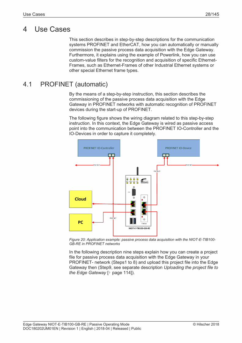
The following figure shows the wiring diagram related to this step-by-stepinstruction. In this context, the Edge Gateway is wired as passive accesspoint into the communication between the PROFINET IO-Controller and theIO-Devices in order to capture it completely.
Figure 20: Application example: passive process data acquisition with the NIOT-E-TIB100-GB-RE in PROFINET networks
In the following description nine steps explain how you can create a projectfile for passive process data acquisition with the Edge Gateway in yourPROFINET- network (Steps1 to 8) and upload this project file into the EdgeGateway then (Step9, see separate description Uploading the project file tothe Edge Gateway [} page 114]).
Edge Gateway NIOT-E-TIB100-GB-RE | Passive Operating ModeDOC180202UM01EN | Revision 1 | English | 2018-04 | Released | Public
© Hilscher 2018

Use Cases 29/145
Prerequisites for the automatic generation of a project file forPROFINET
The following prerequisites have to be met:1. The Edge Gateway is in the passive mode of operation and the
Configuration Mode is active.Otherwise, the assignment of the IP address in step 3 (see below) is notpossible.
2. The software Passive Fieldbus Configurator must be installed on aPC, from which network access to the Edge Gateway can beaccomplished. If this is not the case, install the softweare according tothe installation instructions in the documentation of the Passive FieldbusConfigurator (Document number DOC171103OI01EN).
3. The IP adress of the Edge Gateway must be known.4. For all devices in your PROFINET network suitable GSDML files
should be available. Otherwise additional manual configuration effortwill be necessary.
4.1.1 Step 1 - Start the Passive Fieldbus Configurator.Ø Start the Passive Fieldbus Configurator on your PC, for example via the
entry netIOT – Passive Fieldbus Configurator in the Windows startmenu or by double-clicking at the icon netIOT - Passive FieldbusConfigurator.
ð The entry screen of the Passive Fieldbus Configurator is displayed:
Edge Gateway NIOT-E-TIB100-GB-RE | Passive Operating ModeDOC180202UM01EN | Revision 1 | English | 2018-04 | Released | Public
© Hilscher 2018

Use Cases 30/145
4.1.2 Step 2 - Creating an empty projectØ Build a new project within the Passive Fieldbus Configurator by
selecting Create->New within the introductory menu..Ê The GUI of the Passive Fieldbus Configurator is displayed.
Figure 21: Empty GUI of the Passive Fieldbus Configurator
Edge Gateway NIOT-E-TIB100-GB-RE | Passive Operating ModeDOC180202UM01EN | Revision 1 | English | 2018-04 | Released | Public
© Hilscher 2018

Use Cases 31/145
4.1.3 Step 3 - Adjust basic settings of the Passive Fieldbus Configurator.The Passive Fieldbus Configurator requires the following basic settings:· Setting of IP address· Setting ofSetting of network speed
To do so, proceed as follows:Ø Open the main menu. in order to do so, click at button Menu within the
side menu located at the right side.
Figure 22: Side menu
Ê The main menu is opened.
Figure 23: main menu - Register card "Views"
Edge Gateway NIOT-E-TIB100-GB-RE | Passive Operating ModeDOC180202UM01EN | Revision 1 | English | 2018-04 | Released | Public
© Hilscher 2018

Use Cases 32/145
Ø Select the register card Device assignment.
Figure 24: main menu - Register card "Device assignment"
In order to establish a connection with the Edge-Gateway, the IP address ofthe Edge-Gateway must be assigned to the software. This reqires theGateway being in the passive mode of operation. Proceed as follows:Ø Select the IP addresss of the Edge-Gateway to connect with from the
selection list IP Address in the device selection area. If this list is stillempty yet or the IP address of the Edge Gateway is missing in it,specify the IP address within the input field or click at the cog wheel
symbol at the right and specify the IP address in the dialog boxwhich will appear. This IP address must comply with the valid rules forspecifying IP adresses.
Ø Click at .Ê Finally, the connection with the according Edge Gateway has been
established.
As described in the following, you can check whether a connection to theEdge Gateway has been established:1. In the field Firmware Version the version number of the currently
installed firmware of the Edge Gateway is displayed.2. The status display in the right part of the lower status bar of the Passive
Fieldbus Configurator changes from blue indicating status Idle to yellowindicating status Stopped.
3. In the left part of the status bar now statistic information concerning theEthernet data traffic and zthe interface configuration are displayed.
4. The formerly grayed ot menu entry Connect is activated.
Edge Gateway NIOT-E-TIB100-GB-RE | Passive Operating ModeDOC180202UM01EN | Revision 1 | English | 2018-04 | Released | Public
© Hilscher 2018

Use Cases 33/145
Otherwise the following error message will appear:
Figure 25: Error message "The connection to the device was not possible"
The most probable cause of this error message is the Edge Gateway notbeing in the configuration mode of the passive mode of operation!
Note:For more information concerning the solution of this problem seesection Error handling [} page 117].
Ø In order to adjust the network speed, select the network speed from theselection list Network speed in the area TAP configuration
Figure 26: Selection list Network speed
For the network speed, the following settings are applicable:Setting MeaningAuto Automatic determination of network speed
Select this option if using the Edge Gateway as Software TAP.Possible valueare Auto, 10MBit/s and 100MBit/s.
Fixed network speed of 100 Mbit/sSelect this option if working with an additional Hardware TAP.
Table 7: Settings for network speed
Edge Gateway NIOT-E-TIB100-GB-RE | Passive Operating ModeDOC180202UM01EN | Revision 1 | English | 2018-04 | Released | Public
© Hilscher 2018

Use Cases 34/145
4.1.4 Step 4 - Loading the GSDML filesYou can select PROFINET as network to be captured within the PassiveFieldbus Configurator and load GSDML files containing the devicedescriptions of your connected PROFINET IO-Devices:Ø Right-click at Netzwerk (Tap A).Ê The context menu is opened.
Figure 27: Context menu at network level
Ø Select entry Edit network there.Ê The network wizard is opened.
Figure 28: Network wizard
Ø Within the network wizard, select PROFINET as network protocol withinselection list Network protocol.
Figure 29: Selection list Network protocol.
Edge Gateway NIOT-E-TIB100-GB-RE | Passive Operating ModeDOC180202UM01EN | Revision 1 | English | 2018-04 | Released | Public
© Hilscher 2018

Use Cases 35/145
Ø Click at Finish.Ê Thus, PROFINET has been selected as network protocol.
Figure 30: Import of device descriptions.
Ø Within the item list, click at Import (right of device descriptions). Alternatively, you can point at Network (Tap A) with the mouse pointerand right-click there.
Ê A dialog for the selection of the GSDML file is displayed.Ø Within this dialog, select one or more GSDML files describing your
PROFINET devicews.ð The device descriptions contained within the GSDML file are imported
and the contained items are integrated into the structure tree within thePassive Fieldbus Configurator.
Figure 31: Imported device description within the item list of the Passive FieldbusConfigurator (Example)
Edge Gateway NIOT-E-TIB100-GB-RE | Passive Operating ModeDOC180202UM01EN | Revision 1 | English | 2018-04 | Released | Public
© Hilscher 2018

Use Cases 36/145
4.1.5 Step 5 - Acquiring the start-up of PROFINET communicationSome information relevant for the Edge Gateway and required for itsconfiguration is not contained within the GSDML files of PROFINET. Thisapplies for instance to the MAC addresses of the devices or the FrameIDidentification of the PROFINET frames. In order to avoid manual acquisitionof this information, the Passive Fieldbus Configurator provides thepossibility to acquire this information automatically during start-up ofPROFINET communication between IO-Controller and IO-Devices with theEdge Gateway.
In order to supervise the start-up phase of the PROFINET configuration youfirst have to put the Gateway and the Passive Fieldbus Configurator intorecording mode . This must be accomplished prior to starting thePROFINET configuration. You can achieve this as follows:Ø Within the side menu of the Passive Fieldbus Configurators (right side)
aclick at Connect
:.Ê Now the start-up phase of the PROFINET communication is supervised.
The status within the display in the status bar below changes fromStopped (yellow) to Started (green). The menu entries "Start" and"Disconnect" in the side menu are activated.
Explanation:After successful creation of the connection, the EdgeGateway waits for the connect request and connect response of thePROFINET connection. During the start-up phase of the PROFINETcommunication, the Edge Gateway supervises the data traffic between theController and the Devices. This process may last some seconds. Yet aftercompletion , the Passive Fieldbus Configurator is able to identify thePROFINET-IO-Controller- and PROFINET-IO-Devices within the networkand to display these in the item list.If the button Connect has been grayed out, the connection to the EdgeGateway could not be configured correctly. In this case, try again toconfigure the connection according to step 3.
Edge Gateway NIOT-E-TIB100-GB-RE | Passive Operating ModeDOC180202UM01EN | Revision 1 | English | 2018-04 | Released | Public
© Hilscher 2018

Use Cases 37/145
4.1.6 Step 6 - Signal configurationIn order to activate a signal, proceed as follows:Ø Within the Passive Fieldbus Configurator, drag the signal from the
element list window into the window „Signal configuration“.Ê In window "Signal configuration", a new entry with the name of the
signal is displayed There you can also decide whether the processing ofthis signal shall be continued by transferring it to OPC UA or Node-RED.
Note:In order to reduce CPU time and memory consumption on the EdgeGateway only choose those methods for continuation of processing,which you really need in your specific application.
Ê The entry with the name of the signals within the element list stillremains there, but it is now protected against editing and erasure, i.e.the respective context menu functions are grayed out and deactivated.
Figure 32: Window "Signal configuration" of the Passive Fieldbus Configurator.
Ø Configure the signals in the window Signal configuration of thePassive Fieldbus Configurator. By checking you can decide easily foreach single signal whether the acquired data shall be fetched from theEdge Gateway by OPC UA or shall be made available within Node-RED.
Edge Gateway NIOT-E-TIB100-GB-RE | Passive Operating ModeDOC180202UM01EN | Revision 1 | English | 2018-04 | Released | Public
© Hilscher 2018
Use Cases 38/145
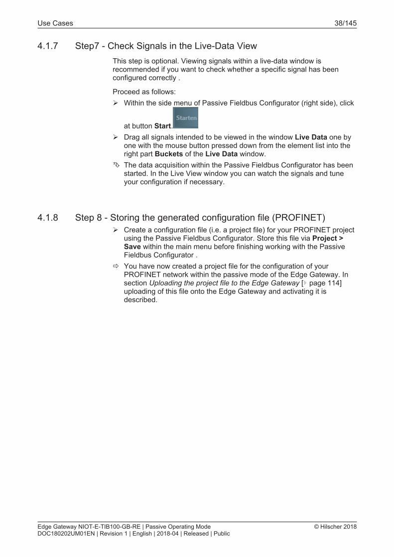
4.1.7 Step7 - Check Signals in the Live-Data ViewThis step is optional. Viewing signals within a live-data window isrecommended if you want to check whether a specific signal has beenconfigured correctly .
Proceed as follows:Ø Within the side menu of Passive Fieldbus Configurator (right side), click
at button Start.Ø Drag all signals intended to be viewed in the window Live Data one by
one with the mouse button pressed down from the element list into theright part Buckets of the Live Data window.
Ê The data acquisition within the Passive Fieldbus Configurator has beenstarted. In the Live View window you can watch the signals and tuneyour configuration if necessary.
4.1.8 Step 8 - Storing the generated configuration file (PROFINET)Ø Create a configuration file (i.e. a project file) for your PROFINET project
using the Passive Fieldbus Configurator. Store this file via Project >Save within the main menu before finishing working with the PassiveFieldbus Configurator .
ð You have now created a project file for the configuration of yourPROFINET network within the passive mode of the Edge Gateway. Insection Uploading the project file to the Edge Gateway [} page 114]uploading of this file onto the Edge Gateway and activating it isdescribed.
Edge Gateway NIOT-E-TIB100-GB-RE | Passive Operating ModeDOC180202UM01EN | Revision 1 | English | 2018-04 | Released | Public
© Hilscher 2018

Use Cases 39/145
4.2 PROFINET (manual)If there is no possibility to record the start-up phase of PROFINET., thedevices can also be configured manually. By the means of a step-by-stepinstruction, this section describes the commissioning of the passive processdata acquisition with the Edge Gateway in PROFINET networks withautomatic recognition of PROFINET devices during the start-up phase ofPROFINET.
For the manual configuration no network connection between configuratorprogram and Edge Gateway is required contrary to the automaticconfiguration. However, the following requirements must be fulfilled:· The software Passive Fieldbus Configurator must be installed on a PC,
from which network access to the Edge Gateway can be accomplished.If this is not the case, install it according to the installation instructions.
· For all devices in your PROFINET network suitable GSDML files shouldbe available. Otherwise additional manual configuration effort will benecessary.
The following figure shows the wiring diagram related to this step-by-stepinstruction. In this context, the Edge Gateway is wired as passive accesspoint into the communication between the PROFINET IO-Controller and theIO-Devices in order to capture it completely.
Figure 33: Application example: passive process data acquisition with the NIOT-E-TIB100-GB-RE in PROFINET networks
In the following description nine steps explain how you can create a projectfile for passive process data acquisition with the Edge Gateway in yourPROFINET network (Steps 1 to 8) and upload this project file into the EdgeGateway then (Step 9, see separate description Uploading the project fileto the Edge Gateway [} page 114]).
Edge Gateway NIOT-E-TIB100-GB-RE | Passive Operating ModeDOC180202UM01EN | Revision 1 | English | 2018-04 | Released | Public
© Hilscher 2018

Use Cases 40/145
4.2.1 Step 1 - Start the Passive Fieldbus Configurator.Ø Start the Passive Fieldbus Configurator on your PC, for example via the
entry netIOT – Passive Fieldbus Configurator in the Windows startmenu or by double-clicking at the icon netIOT - Passive FieldbusConfigurator.
ð The entry screen of the Passive Fieldbus Configurator is displayed:
4.2.2 Step 2 - Creating an empty projectØ Build a new project within the Passive Fieldbus Configurator by
selecting Create->New within the introductory menu..Ê The GUI of the Passive Fieldbus Configurator is displayed.
Figure 34: Empty GUI of the Passive Fieldbus Configurator
Edge Gateway NIOT-E-TIB100-GB-RE | Passive Operating ModeDOC180202UM01EN | Revision 1 | English | 2018-04 | Released | Public
© Hilscher 2018

Use Cases 41/145
4.2.3 Step 3 - Adjust basic settings of the Passive Fieldbus ConfiguratorThe Passive Fieldbus Configurator requires the following basic settings:· Setting of network speed
To do so, proceed as follows:Ø Open the main menu. in order to do so, click at button Menu within the
side menu located at the right side.
Figure 35: Side menu
Ê The main menu is opened.
Figure 36: main menu - Register card "Views"
Ø Select the register card Device assignment.
Figure 37: main menu - Register card "Device assignment"
Edge Gateway NIOT-E-TIB100-GB-RE | Passive Operating ModeDOC180202UM01EN | Revision 1 | English | 2018-04 | Released | Public
© Hilscher 2018

Use Cases 42/145
The main menu of the Passive Fieldbus Configurator consists of two areas:· the area Device selection (top)· the area TAP Configuration (down)
The network speed is selected in the area TAP configurationØ In order to adjust the network speed, select the network speed from the
selection list Network speed in the area TAP configuration
Figure 38: Selection list Network speed
For the network speed, the following settings are applicable:Setting MeaningAuto Automatic determination of network speed
Select this option if using the Edge Gateway as Software TAP.Possible valueare Auto, 10MBit/s and 100MBit/s.
Fixed network speed of 100 Mbit/sSelect this option if working with an additional Hardware TAP.
Table 8: Settings for network speed
Edge Gateway NIOT-E-TIB100-GB-RE | Passive Operating ModeDOC180202UM01EN | Revision 1 | English | 2018-04 | Released | Public
© Hilscher 2018

Use Cases 43/145
4.2.4 Step 4 - Loading the GSDML filesYou can select PROFINET as network to be captured within the PassiveFieldbus Configurator and load GSDML files containing the devicedescriptions of your connected PROFINET IO-Devices:Ø Right-click at Netzwerk (Tap A).Ê The context menu is opened.
Figure 39: Context menu at network level
Ø Select entry Edit network there.Ê The network wizard is opened.
Figure 40: Network wizard
Ø Within the network wizard, select PROFINET as network protocol withinselection list Network protocol.
Figure 41: Selection list Network protocol.
Edge Gateway NIOT-E-TIB100-GB-RE | Passive Operating ModeDOC180202UM01EN | Revision 1 | English | 2018-04 | Released | Public
© Hilscher 2018

Use Cases 44/145
Ø Click at Finish.Ê Thus, PROFINET has been selected as network protocol.
Figure 42: Import of device descriptions.
Ø Within the item list, click at Import (right of device descriptions). Alternatively, you can point at Network (Tap A) with the mouse pointerand right-click there.
Ê A dialog for the selection of the GSDML file is displayed.Ø Within this dialog, select one or more GSDML files describing your
PROFINET devicews.ð The device descriptions contained within the GSDML file are imported
and the contained items are integrated into the structure tree within thePassive Fieldbus Configurator.
Figure 43: Imported device description within the item list of the Passive FieldbusConfigurator (Example)
Edge Gateway NIOT-E-TIB100-GB-RE | Passive Operating ModeDOC180202UM01EN | Revision 1 | English | 2018-04 | Released | Public
© Hilscher 2018

Use Cases 45/145
4.2.5 Step 5 - Manual configuration of PROFINET IO-Controller and -Devices
All devices of the PROFINET network (PROFINET IO-Controller and IO-Devices) must now be configured manually. Proceed as follows:
Configuring Controller / IO-Controller
The element IO-Controller is the root element of the configuration tree.Therefore, it is the first element of this tree to be configured. Proceed asfollows:Ø Open the context menu. Right-click at Configuration within the element
list.Ê The context menu appears.
Figure 44: Context menu entry “Add controller”
Ø Choose the only menu entry Add controller.Ê The controller assistant is opened:
Figure 45: Controller assistant
Edge Gateway NIOT-E-TIB100-GB-RE | Passive Operating ModeDOC180202UM01EN | Revision 1 | English | 2018-04 | Released | Public
© Hilscher 2018

Use Cases 46/145
Ø Enter the name of your PROFINET IO-Controller into the field Name.This field is mandatory.
Ø Enter the MAC address of the PROFINET IO-Controller into field Name.This field is mandatory.
Ø Click at Finish.ð Now, the controller is configured.
Configuring Device / IO-Device
One or more IO devices are subordinated to an IO controller. In order toconfigure these, proceed as follows:Ø Open the context menu. Rightclick at the IO controller within the
element listÊ The context menu appears.
Figure 46: Context menu entry "Add device"
Ø Select the entry Add deviceÊ The device assistant is opened:
Figure 47: Device assistant
Edge Gateway NIOT-E-TIB100-GB-RE | Passive Operating ModeDOC180202UM01EN | Revision 1 | English | 2018-04 | Released | Public
© Hilscher 2018

Use Cases 47/145
Ø Enter the name of the device (NameOfStation) into the field Name. Thedevice name must be unique within the network. This field is mandatory.
Ø Enter the Device ID into the field Device ID. The Device ID is a uniqueidentification number for the device. This field is mandatory.
Ø Enter the Manufacturer ID into the field Manufacturer ID. TheManufacturer ID is a unique identification number which is assigned tothe manufacturer by the PNO , This field is mandatory.
Ø Enter the MAC address of the device into the field MAC address. TheMAC address consists of six two-digit hexadecimal values separated bycolons. This field is mandatory.
Ø Click at Finish.ð Now, the IO device is configured.
To configure a module within the device configuration, perform the followingsteps:
Configure module
One or more modules are subordinated to a device. In order to configurethese, proceed as follows:Ø Open the context menu. Rightclick at the IO Device within the element
listÊ The context menu is opened.
Figure 48: Context menu entry "Add module"
Ø Select the entry Addodule
Edge Gateway NIOT-E-TIB100-GB-RE | Passive Operating ModeDOC180202UM01EN | Revision 1 | English | 2018-04 | Released | Public
© Hilscher 2018

Use Cases 48/145
ð The module assistant is opened.
Figure 49: Module assistant
Ø Specify the desired name of the module in the field Name. This namecan freely be chosen, however, it may not be empty.
Ø Specify the identification number of the module of your PROFINETdevice in the field Identification number either in decimal format in theleft input field or in hexadecimal format in the right input field..
Ø Specify the slot number in the field Slot number either in decimalformat in the left input field or in hexadecimal format in the right inputfield..
Ø The other fields are optional. You can specify the order number in field Order number. An additional descriptive Text can be specified in field Infotext.
Ø Click at Finish.ð Now, the module is configured.
Edge Gateway NIOT-E-TIB100-GB-RE | Passive Operating ModeDOC180202UM01EN | Revision 1 | English | 2018-04 | Released | Public
© Hilscher 2018

Use Cases 49/145
To configure a submodule within the device configuration, perform thefollowing steps:
Configure submodule
One or more submodules are subordinated to a module.Ø Open the context menu. Rightclick at the module within the element list.Ê The context menu is opened.
Figure 50: Context menu entry "Add submodule"
Ø Select the entry Add submoduleð The submodule assistant is opened.
Figure 51: First page of dialog "Submodule assistant".
Ø Specify the desired name of the submodule (subslot) in the field Name.
Edge Gateway NIOT-E-TIB100-GB-RE | Passive Operating ModeDOC180202UM01EN | Revision 1 | English | 2018-04 | Released | Public
© Hilscher 2018

Use Cases 50/145
Ø Specify the identification number of the submodule of your PROFINETdevice in the field Identification number either in decimal format in theleft input field or in hexadecimal format in the right input field..
Ø Specify the subslot number in the field Subslot number of yourPROFINET device either in decimal format in the left input field or inhexadecimal format in the right input field..
Ø Specify whether the submodule holds input and/or output values bychecking the according checkboxes and specify the according datalength in bytes.
Note:At least one of the two input fields Input data length and Output datalength must be checked. For submodules working bidirectionally,both directions have to be selected.
Ø Specify the length of the IOCS byte within the field IOCS byte lengtheither decimally in the left input field or hexadecimally in the rightinputfield.
Ø Specify the length of the IOPS byte within the field IOPS byte lengtheither decimally in the left input field or hexadecimally in the rightinputfield.
The following specification is optional.Ø Here you can specify additional info text.
In order to proceed to the second page of the submodule assistant,click atContinue.The following dialog appears:
Figure 52: Second page of dialog "Submodule assistant".
This page offers the possibility to specify the following parametersconcerning the frame configuration:
The selection list Frames enables specifying of multiple process dataframes, for instance one for the each data direction (input and output) atbidirectional submodules.
Edge Gateway NIOT-E-TIB100-GB-RE | Passive Operating ModeDOC180202UM01EN | Revision 1 | English | 2018-04 | Released | Public
© Hilscher 2018

Use Cases 51/145
By clicking at the green plus symbol it is possible to specify information foran additional frame. Vice versa, the currently selected frame wiothin the listcan be deleted with all related information by clicking at the "trashcan"symbol.
For each frame, the following frame-related information can be stored here:Ø Specify a freely selectable name for the frame in field Name. The
default name to be used when a new frame is generated is EmptyFrame.
Ø Specify the frame ID in the field Frame ID either in decimal format in theleft input field (Range of values 0…65535) or in hexadecimal format inthe right input field (Range of values 0…0xFFFF).
Ø Specify te data direction of the frame in field Frame direction. You canselect between these frame directions:
· Input· OutputØ Specify the offset of the data byte in field Data byte offset either
decimally in the left input field (Range of values 0…65535) orhexadecimally in the right input field (Range of values 0...0xFFFF).
Ø Specify the offset of the IOCS byte in field IOCS byte offset eitherdecimally in the left input field (Range of values 0…65535) orhexadecimally in the right input field (Range of values 0...0xFFFF).
Ø Specify the SendClockFactor in the field SendClockFactor either indecimal format in the left input field (Range of values 0…65535) or inhexadecimal format in the right input field (Range of values 0…0xFFFF).
Ø Specify the ReductionRatioFactor in the field ReductionRatioFactoreither in decimal format in the left input field (Range of values 0…65535)or in hexadecimal format in the right input field (Range of values 0…0xFFFF).
1. In order to store the configured device/module/submodule you haveentered within this dialog:Ø Click at Finish.ð The entered configuration data for the device/module are stored within
the project.
If for any reason you do not want to store the data, you can leave the dialogby clicking at Cancel.
There are two possibilities to configure a variable within the deviceconfiguration. Either you can load a GSDML file describing this variable oryou perform the following steps:
Edge Gateway NIOT-E-TIB100-GB-RE | Passive Operating ModeDOC180202UM01EN | Revision 1 | English | 2018-04 | Released | Public
© Hilscher 2018

Use Cases 52/145
Configure variable
One or more variables are subordinated to a submodule. In order toconfigure these variables, proceed as follows:Ø Open the context menu. Rightclick at the submodule within the element
listÊ The context menu is opened.
Figure 53: Context menu entry "Add variable"
Ø Select the entry Add variableÊ The variable assistant is opened:
Figure 54: Variable Wizard - first page (Parameter)
Edge Gateway NIOT-E-TIB100-GB-RE | Passive Operating ModeDOC180202UM01EN | Revision 1 | English | 2018-04 | Released | Public
© Hilscher 2018

Use Cases 53/145
Within the Variable Wizard, the following specifications concerning theconfiguration are made:
NameØ Specify the name of the variable here. This field is mandatory. As long
as no input hs been done, a red frame is displayed around the inputfield Name and the button Finish is deactivated and grayed out. This nameis also displayed in the variable area within the block VariableInfo, see section „Variable area“.
UnitØ This field contains the unit to be applied to the variable. The field is
optional and purely informative.
TypeØ Specify the datatype of the variable here. This field is mandatory.
Note:List of suitable datatypesA list of suitable datatypes can be found at Supported Data Types.
Ø The length of the data type specified under Type given as number ofbits. Specify this length either in the left input field decimally or in theright input field hexadecimally. This value depends on the choice at Type. At every selection of thetype, the maximum allowed value matching the length of the data typein bits, is used as default value. However, you can also selct lowervalues. In such a case, the remaining bits are extended up to the fulldatatype also taking into account the sign, if necessary. This field is mandatory.
Byte orderØ Specify here, whether the order of bytes within a word shall be swapped
Swapped or not(Not swapped). This field is mandatory.
Ø This data field contains the offset of the variable to the beginning ogf theIO Data Object in the PROFINET Frame given as number of bytes.This field is mandatory.
Bit offsetØ This data field contains the number of bits which the variable has been
shiftted at the beginning of the IO Data Object. A non-negative valuebetween 0 and 7 has to be specified here.
Edge Gateway NIOT-E-TIB100-GB-RE | Passive Operating ModeDOC180202UM01EN | Revision 1 | English | 2018-04 | Released | Public
© Hilscher 2018

Use Cases 54/145
DirectionØ This selection list allows you to select the signal direction to be applied.
Applicable options are:· Input· Output
The signal direction is also displayed within the variable area. This field ismandatoryØ Click at Next.Ê The second page of the dialog Add variable appears:
Figure 55: Dialog Variable Wizard - third page (Normalization/Downsampling)
On this page you can specify how to normalize the measured data.
The fields in dialog Variable Wizard have the following meaning:
Type
Here select the normalization type of the list. If the option None is chosen, the values Scale and Offset are set to 0 andthus no normalization of the measured data takes place. Otherwise, it ispossible to perform a user-defined normalization using the fields Scale andOffset. During this normalization, the initial value is first multiplied with the factorScale and then the Offset is added to the product.
Scale
Specify the factor Scale for the user-defined normalization here.
Edge Gateway NIOT-E-TIB100-GB-RE | Passive Operating ModeDOC180202UM01EN | Revision 1 | English | 2018-04 | Released | Public
© Hilscher 2018

Use Cases 55/145
Offset
Specify the offset for the user-defined normalization here:Ø Click at Finish in order to display the configured variable in your project.ð The entered configuration data for the variable are stored within the
project.
Downsampling area
This area contains the specifications for performing downsampling in thePassive Fieldbus Configurator.
Selection list Downsample Type
The following options are provided by selection list Downsample Type.Option DescriptionSwitched off No downsampling of data occurs. All data values are acquired by
the network at their individual cycle.Only on change In this setting, acquired data will be transferred to the subsequent
processing only if changes occur.Downsampling If downsampling has been activated, the data are regularly sampled
after a defined time interval (the downsampling rate) and only thosesampled values are transferred to subsequent processing. Thistime interval is specified in input field Downsample Rate.
Input field Downsample-Rate
If the Downsample Type Downsampling has been selected, in this inputfield the downsample rate can be specified in units of milliseconds. Theallowed range of values extends from 1 to 1000 Milliseconds. See thefollowing figure.
Figure 56: Edit custom value filter – Downsampling-Type and -Rate
Edge Gateway NIOT-E-TIB100-GB-RE | Passive Operating ModeDOC180202UM01EN | Revision 1 | English | 2018-04 | Released | Public
© Hilscher 2018

Use Cases 56/145
4.2.6 Step 6 - Signal configurationIn order to activate a signal, proceed as follows:Ø Within the Passive Fieldbus Configurator, drag the signal from the
element list window into the window „Signal configuration“.Ê In window "Signal configuration", a new entry with the name of the
signal is displayed There you can also decide whether the processing ofthis signal shall be continued by transferring it to OPC UA or Node-RED.
Note:In order to reduce CPU time and memory consumption on the EdgeGateway only choose those methods for continuation of processing,which you really need in your specific application.
Ê The entry with the name of the signals within the element list stillremains there, but it is now protected against editing and erasure, i.e.the respective context menu functions are grayed out and deactivated.
Figure 57: Window "Signal configuration" of the Passive Fieldbus Configurator.
Ø Configure the signals in the window Signal configuration of thePassive Fieldbus Configurator. By checking the checkbox, you canseparately determine for each single PROFINET IO signal, whether theacquired data shall be fetched from the Edge Gateway by OPC-UA ortransferred into the cloud by Node-RED. whether
Edge Gateway NIOT-E-TIB100-GB-RE | Passive Operating ModeDOC180202UM01EN | Revision 1 | English | 2018-04 | Released | Public
© Hilscher 2018

Use Cases 57/145
4.2.7 Step 7 - Check Signals in the Live-Data ViewThis step is optional. Viewing signals within a live-data window isrecommended if you want to check whether a specific signal has beenconfigured correctly
Proceed as follows to start recording the PROFINET network traffic:Ø Within the side menu of Passive Fieldbus Configurator (right side), click
at button Start.Ø Drag all signals intended to be viewed in the window Live Data one by
one with the mouse button pressed down from the element list into theright part Buckets of the Live Data window.
Ê The data acquisition within the Passive Fieldbus Configurator has beenstarted. In the Live View window you can watch the signals and tuneyour configuration if necessary.
4.2.8 Step 8 - Storing the generated configuration file (PROFINET)Ø Create a configuration file (i.e. a project file) for your PROFINET project
using the Passive Fieldbus Configurator. Store this file via Project >Save within the main menu before finishing working with the PassiveFieldbus Configurator .
ð You have now created a project file for the configuration of yourPROFINET network within the passive mode of the Edge Gateway. Insection Uploading the project file to the Edge Gateway [} page 114]uploading of this file onto the Edge Gateway and activating it isdescribed.
Edge Gateway NIOT-E-TIB100-GB-RE | Passive Operating ModeDOC180202UM01EN | Revision 1 | English | 2018-04 | Released | Public
© Hilscher 2018

Use Cases 58/145
4.3 EtherCAT (automatic)This section describes step-by-step the commissioning of the passiveprocess data acquisition of the Edge Gateway in an EtherCAT networkusing an ENI file.
In the following description eight steps explain how you can create a projectfile for passive process data acquisition with the Edge Gateway in yourEtherCAT network (Steps1 to 7) without any manual slave configurationand upload this project file into the Edge Gateway then (Step 8, seeseparate description Uploading the project file to the EdgeGateway [} page 114]).
Contrary to the PROFINET configuration, the EtherCAT configuration canbe done offline, i.e. without connection to the Edge Gateway.
The following figure shows the wiring diagram related to this step-by-stepinstruction. The Edge Gateway is wired as passive access point betweenEtherCAT Master and the first EtherCAT Slave in order to capture thenetwork communication between those completely.
Figure 58: Wiring diagram for passive process data acquisition with the Edge GatewayNIOT-E-TIB100-GB-RE in EtherCAT networks
Edge Gateway NIOT-E-TIB100-GB-RE | Passive Operating ModeDOC180202UM01EN | Revision 1 | English | 2018-04 | Released | Public
© Hilscher 2018

Use Cases 59/145
The following prerequisites must be fulfilled for the EtherCAT configuration.1. The software Passive Fieldbus Configurator must be installed on a PC,
from which network access to the Edge Gateway can be accomplished.If this is not the case, install it according to the installation instructions.
2. The IP address of the Edge Gateway to be used must be known.3. A suitable ENI-File for your EtherCAT project must be present.
Note:ENI files from TwinCAT are supported. ENI files from otherEngineering Tools can only be read if these contain detaileddescriptions of the RxPDOs and TxPDOs. At Codesys the ENI fileuses other bus addresses as they have been parameterized on thenetwork. For affected versions of Codesys, the bus addresses mustbe manually adapted within the Passive FB Configurator afterimporting the ENI files. See .
If there is no suitable ENI file present, a manual configuration can be made,see EtherCAT (manual) [} page 69].
4.3.1 Step 1 - Program startØ Start the Passive Fieldbus Configurator on your PC, for example via the
entry netIOT – Passive Fieldbus Configurator in the Windows startmenu or by double-clicking at the icon netIOT - Passive FieldbusConfigurator.
ð The entry screen of the Passive Fieldbus Configurator is displayed:
4.3.2 Step 2 - Creating an empty projectØ Build a new project within the Passive Fieldbus Configurator by
selecting Create->New within the introductory menu..
Ê The (still empty) GUI of the Passive Fieldbus Configurator is displayed.
Edge Gateway NIOT-E-TIB100-GB-RE | Passive Operating ModeDOC180202UM01EN | Revision 1 | English | 2018-04 | Released | Public
© Hilscher 2018

Use Cases 60/145
4.3.3 Step 3 - Adjust basic settings of the Passive Fieldbus Configurator.The Passive Fieldbus Configurator requires the following basic settings:· Setting of IP address· Setting ofSetting of network speed
To do so, proceed as follows:Ø Open the main menu. in order to do so, click at button Menu within the
side menu located at the right side.
Figure 59: Side menu
Ê The main menu is opened.
Figure 60: main menu - Register card "Views"
Edge Gateway NIOT-E-TIB100-GB-RE | Passive Operating ModeDOC180202UM01EN | Revision 1 | English | 2018-04 | Released | Public
© Hilscher 2018

Use Cases 61/145
Ø Select the register card Device assignment.
Figure 61: main menu - Register card "Device assignment"
In order to establish a connection with the Edge-Gateway, the IP address ofthe Edge-Gateway must be assigned to the software. This reqires theGateway being in the passive mode of operation. Proceed as follows:Ø Select the IP addresss of the Edge-Gateway to connect with from the
selection list IP Address in the device selection area. If this list is stillempty yet or the IP address of the Edge Gateway is missing in it,specify the IP address within the input field or click at the cog wheel
symbol at the right and specify the IP address in the dialog boxwhich will appear. This IP address must comply with the valid rules forspecifying IP adresses.
Ø Click at .Ê Finally, the connection with the according Edge Gateway has been
established.
As described in the following, you can check whether a connection to theEdge Gateway has been established:1. In the field Firmware Version the version number of the currently
installed firmware of the Edge Gateway is displayed.2. The status display in the right part of the lower status bar of the Passive
Fieldbus Configurator changes from blue indicating status Idle to yellowindicating status Stopped.
3. In the left part of the status bar now statistic information concerning theEthernet data traffic and zthe interface configuration are displayed.
4. The formerly grayed ot menu entry Connect is activated.
Edge Gateway NIOT-E-TIB100-GB-RE | Passive Operating ModeDOC180202UM01EN | Revision 1 | English | 2018-04 | Released | Public
© Hilscher 2018

Use Cases 62/145
Otherwise the following error message will appear:
Figure 62: Error message "The connection to the device was not possible"
The most probable cause of this error message is the Edge Gateway notbeing in the configuration mode of the passive mode of operation!
Note:For more information concerning the solution of this problem seesection Error handling [} page 117].
Ø In order to adjust the network speed, select the network speed from theselection list Network speed in the area TAP configuration
Figure 63: Selection list Network speed
For the network speed, the following settings are applicable:Setting MeaningAuto Automatic determination of network speed
Select this option if using the Edge Gateway as Software TAP.Possible valueare Auto, 10MBit/s and 100MBit/s.
Fixed network speed of 100 Mbit/sSelect this option if working with an additional Hardware TAP.
Table 9: Settings for network speed
Edge Gateway NIOT-E-TIB100-GB-RE | Passive Operating ModeDOC180202UM01EN | Revision 1 | English | 2018-04 | Released | Public
© Hilscher 2018

Use Cases 63/145
4.3.4 Step 4 - Upload the ENI fileHow to load an ENI file with the device description of your EtherCAT-Master and the connected EtherCAT-Slaves into the Passive FieldbusConfigurator (ENI = EtherCAT Network Information):Ø Right-click at Network (Tap A).Ê The context menu is opened.
Figure 64: Context menu at network level
Ø There select the topmost entry Edit network.Ê The first page of the Network Wizard for EtherCAT is opened.
Figure 65: First page of the Network Wizard for EtherCAT
Ø Within the network wizard, select EtherCAT as network protocol.
Figure 66: Selection of network protocol
Edge Gateway NIOT-E-TIB100-GB-RE | Passive Operating ModeDOC180202UM01EN | Revision 1 | English | 2018-04 | Released | Public
© Hilscher 2018

Use Cases 64/145
Ø Click at Next.Ê The second page of the Network Wizard for EtherCAT is opened.
Figure 67: Second page of the Network Wizard for EtherCAT
Ø In the selection Direction the data direction of the EtherCAT networkcan be configured.
Option MeaningAutomatic The recognition of the data direction is done
automatically. Select this option by default. If you apply a Hardware-TAP, automatic recognition ofthe data direction is necessarily required.
Port 0|2 input, Port 1|3output
The side of the network close to the PLC is connectedto the upper RJ45 connector of the field bus interface(Port 0). By the selection of a fixed direction thedecoding performance on the Edge Gateway isincreased. Select this option if not using an additionalHardware TAP.
Port 0|2 output, Port 1|3input
The side of the network close to the PLC is connectedto the lower RJ45 connector of the field bus interface(Port 1). By the selection of a fixed direction thedecoding performance on the Edge Gateway isincreased. Select this option if not using an additionalHardware TAP.
Table 10: Options for the data direction within an EtherCAT network
Edge Gateway NIOT-E-TIB100-GB-RE | Passive Operating ModeDOC180202UM01EN | Revision 1 | English | 2018-04 | Released | Public
© Hilscher 2018

Use Cases 65/145
Ø Click at Finish.
Figure 68: EtherCAT Import
Ø Click at Import (right beside Device descriptions).Ê A dialog for selcting the ENI file is displayed.Ø Select the ENI file for your EtherCAT device there.ð The device descriptions contained within the ENI file are imported and
integrated into the structure tree within the element list of the PassiveFieldbus Configurator.
Edge Gateway NIOT-E-TIB100-GB-RE | Passive Operating ModeDOC180202UM01EN | Revision 1 | English | 2018-04 | Released | Public
© Hilscher 2018

Use Cases 66/145
4.3.5 Step 5 - Signal configurationIn order to activate a signal, proceed as follows:Ø Within the Passive Fieldbus Configurator, drag the signal from the
element list window into the window „Signal configuration“. To do so, check the signal(s) in window Element List and keep themouse button pressed while moving the mouse cursor to the window"Signal configuration". The figure below shows the state beforereleasing the mouse button. The red line is used only for clarification.
Figure 69: Signal configuration - during Drag&Drop
Ê If the mouse button is released, a new entry with the name of the signalis displayed in window „Signal configuration“.
The entry with the name of the signals within the element list still remainsthere, but it is now protected against editing and erasure, i.e. the respectivecontext menu functions are grayed out and deactivated.Ø Configure the signals in the window Signal configuration of the
Passive Fieldbus Configurator. In window "Signal configuration", a newentry with the name of the signal is displayed. For each singleEtherCAT signal, you can also decide there, whether the acquired datashall be fetched from the Edge Gateway by OPC-UA or transferred intothe cloud by Node-RED.
Note:In order to reduce CPU time and memory consumption on the EdgeGateway only choose those methods for continuation of dataprocessing, which you really need in your specific application.
Edge Gateway NIOT-E-TIB100-GB-RE | Passive Operating ModeDOC180202UM01EN | Revision 1 | English | 2018-04 | Released | Public
© Hilscher 2018

Use Cases 67/145
4.3.6 Step 6 - Check Signals in the Live-Data ViewThis step is optional. However, it allows a quick and easy check whether asignal has been configured correctly.
The Live Data window consists of a display area on the left side, which canbe separated into some stacked parts (Buckets), and of an area on the rightside only containing a register card buckets that lists the current signalsand their assignment to these areas (Buckets)
Figure 70: Adding signals to the Live Data window
To view and record arbitrary signals of your choice within the live datawindow, start recording as follows:Ø Drag all signals intended to be viewed in the window Live Data one by
one with the mouse button pressed down from the element list into theright part Buckets of the Live Data window.
Ê The data acquisition within the Passive Fieldbus Configurator has beenstarted. In the Live View window you can watch the signals and tuneyour configuration if necessary.
Edge Gateway NIOT-E-TIB100-GB-RE | Passive Operating ModeDOC180202UM01EN | Revision 1 | English | 2018-04 | Released | Public
© Hilscher 2018

Use Cases 68/145
4.3.7 Step 7 - Storing the generated configuration file (EtherCAT)Ø Create a configuration file (i.e. project file) for your EtherCAT project
using the Passive Fieldbus Configurator. Store this file via Project >Savewithin the main menu before finishing working with the PassiveFieldbus Configurator .
ð You have now created a project file in the *.fbcfg format for theconfiguration of your EtherCAT network within the passive mode of theEdge Gateway. In section Uploading the project file to the EdgeGateway [} page 114] uploading of this file onto the Edge Gateway andactivating it there is described.
Edge Gateway NIOT-E-TIB100-GB-RE | Passive Operating ModeDOC180202UM01EN | Revision 1 | English | 2018-04 | Released | Public
© Hilscher 2018

Use Cases 69/145
4.4 EtherCAT (manual)this section describes themethod for manually commissioning the passiveprocess data acquisition with the Edge Gateway in EtherCAT networks.
This method is especially suited if no ENI file for your EtherCAT network ispresent. This means, all devices of the EtherCAT network have to beconfigured manually.
The following figure shows the wiring diagram related to this step-by-stepinstruction. The Edge Gateway is wired as passive access point betweenEtherCAT Master and the first EtherCAT Slave in order to capture thenetwork communication between those completely.
Figure 71: Wiring diagram for passive process data acquisition with the Edge GatewayNIOT-E-TIB100-GB-RE in EtherCAT networks
In the following description nine steps explain how you can create a projectfile for passive process data acquisition with the Edge Gateway in yourEtherCAT- network (Steps1 to 8) and upload this project file into the EdgeGateway then (Step9, see separate description Uploading the project file tothe Edge Gateway [} page 114]).
Edge Gateway NIOT-E-TIB100-GB-RE | Passive Operating ModeDOC180202UM01EN | Revision 1 | English | 2018-04 | Released | Public
© Hilscher 2018

Use Cases 70/145
For this, the following prerequisites must be fulfilled:1. The Passive Fieldbus Configurator has to be installed on a PC that
allows you to access to Edge Gateway via the netwok. If this software isnot installed yet, then install it according to the installation instructionfirst.
2. You have to know the IP address of the Edge Gateway.
4.4.1 Step 1 - Start the Passive Fieldbus Configurator.Ø Start the Passive Fieldbus Configurator on your PC, for example via the
entry netIOT – Passive Fieldbus Configurator in the Windows startmenu or by double-clicking at the icon netIOT - Passive FieldbusConfigurator.
ð The entry screen of the Passive Fieldbus Configurator is displayed:
4.4.2 Step 2 - Creating an empty projectØ Build a new project within the Passive Fieldbus Configurator by
selecting the right buttonCreate->New within the introductory menu..
Ê The (still empty) GUI of the Passive Fieldbus Configurator is displayed.
Edge Gateway NIOT-E-TIB100-GB-RE | Passive Operating ModeDOC180202UM01EN | Revision 1 | English | 2018-04 | Released | Public
© Hilscher 2018

Use Cases 71/145
4.4.3 Step 3 - Adjust basic settings of the Passive Fieldbus Configurator.The Passive Fieldbus Configurator requires the following basic settings:· Setting of network speed
To do so, proceed as follows:Ø Open the main menu. in order to do so, click at button Menu within the
side menu located at the right side.
Figure 72: Side menu
Ê The main menu is opened.
Figure 73: main menu - Register card "Views"
Ø Select the register card Device assignment.
Figure 74: main menu - Register card "Device assignment"
Edge Gateway NIOT-E-TIB100-GB-RE | Passive Operating ModeDOC180202UM01EN | Revision 1 | English | 2018-04 | Released | Public
© Hilscher 2018

Use Cases 72/145
The main menu of the Passive Fieldbus Configurator consists of two areas:· the area Device selection (top)· the area TAP Configuration (down)
The network speed is selected in the area TAP configuration.Ø In order to adjust the network speed, select the network speed from the
selection list Network speed in the area TAP configuration
Figure 75: Selection list Network speed
For the network speed, the following settings are applicable:Setting MeaningAuto Automatic determination of network speed
Select this option if using the Edge Gateway as Software TAP.Possible valueare Auto, 10MBit/s and 100MBit/s.
Fixed network speed of 100 Mbit/sSelect this option if working with an additional Hardware TAP.
Table 11: Settings for network speed
Edge Gateway NIOT-E-TIB100-GB-RE | Passive Operating ModeDOC180202UM01EN | Revision 1 | English | 2018-04 | Released | Public
© Hilscher 2018
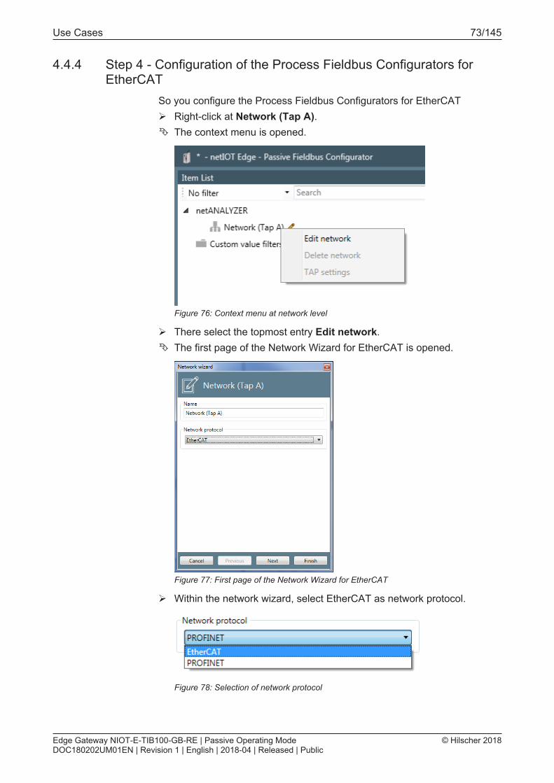
Use Cases 73/145
4.4.4 Step 4 - Configuration of the Process Fieldbus Configurators forEtherCAT
So you configure the Process Fieldbus Configurators for EtherCATØ Right-click at Network (Tap A).Ê The context menu is opened.
Figure 76: Context menu at network level
Ø There select the topmost entry Edit network.Ê The first page of the Network Wizard for EtherCAT is opened.
Figure 77: First page of the Network Wizard for EtherCAT
Ø Within the network wizard, select EtherCAT as network protocol.
Figure 78: Selection of network protocol
Edge Gateway NIOT-E-TIB100-GB-RE | Passive Operating ModeDOC180202UM01EN | Revision 1 | English | 2018-04 | Released | Public
© Hilscher 2018

Use Cases 74/145
Ø Click at Next.Ê The second page of the Network Wizard for EtherCAT is opened.
Figure 79: Second page of the Network Wizard for EtherCAT
Ø In the selection Direction the data direction of the EtherCAT networkcan be configured.
Option MeaningAutomatic The recognition of the data direction is done
automatically. Select this option by default. If you apply a Hardware-TAP, automatic recognition ofthe data direction is necessarily required.
Port 0|2 input, Port 1|3output
The side of the network close to the PLC is connectedto the upper RJ45 connector of the field bus interface(Port 0). By the selection of a fixed direction thedecoding performance on the Edge Gateway isincreased. Select this option if not using an additionalHardware TAP.
Port 0|2 output, Port 1|3input
The side of the network close to the PLC is connectedto the lower RJ45 connector of the field bus interface(Port 1). By the selection of a fixed direction thedecoding performance on the Edge Gateway isincreased. Select this option if not using an additionalHardware TAP.
Table 12: Options for the data direction within an EtherCAT network
Ø Click at Finish.
Edge Gateway NIOT-E-TIB100-GB-RE | Passive Operating ModeDOC180202UM01EN | Revision 1 | English | 2018-04 | Released | Public
© Hilscher 2018

Use Cases 75/145
4.4.5 Step 5 – Manual configuration of the EtherCAT networkIf there is no ENI file present for the EWtherCAT network, all devices of theEtherCAT network must be configured manually. To do so, you have tomodel the network structure manually within the structure tree of thePassive Fieldbus Configurator, by performing both of the steps of workdescribed in the following (if necessary, repeatedly), until all slave devicesand variables are present.1. Add a slave device to the network2. Add variables to a master or slave device
Add a slave device
When manually defining a new slave, the configuration data must beentered via the dialog Add slave(Context menu entry Add slave). Bei dermanuellen Definition eines neuen Slaves müssen die Konfigurationsdatenüber den Dialog Slave einfügen eingegeben werden (Kontextmenü-EintragGerät hinzufügen). Um ein Slave-Gerät im Strukturbaum innerhalb derElement-Liste des Passive Fieldbus Configurators hinzuzufügen unddessen Konfigurationsdaten manuell einzugeben, gehen Sie wie folgt vor:Ø Within the element list, rightclick at the Master under which the variable
shall be added.Ê Open the context menu of the master.
Figure 80: Context menu for EtherCAT Master
Ø Within the context menu, click at the entry Add device
Edge Gateway NIOT-E-TIB100-GB-RE | Passive Operating ModeDOC180202UM01EN | Revision 1 | English | 2018-04 | Released | Public
© Hilscher 2018

Use Cases 76/145
Ê The first page of the dialog Add slave is opened.
Figure 81: Dialog „Add slave - first page (Name)"
Ø Under Name specify the name which shall identify the EtherCAT Slavedevice in future.
Ø Click at Next.Ê The second page of the dialog Add slave is opened.
Figure 82: Dialog Add slave - second page"(Parameter)
Within the dialog Add slave, the following specifications concerning theconfiguration are made:
Edge Gateway NIOT-E-TIB100-GB-RE | Passive Operating ModeDOC180202UM01EN | Revision 1 | English | 2018-04 | Released | Public
© Hilscher 2018

Use Cases 77/145
Configured station address
This address is used at the node addressing method. The value is entereddecimally in the left input field or hexadecimally in the right input field. Theallowed range of values for the configured station address extends from 0to 0xFFFF.
Note:For more information on the node addressing method, see theEtherCAT specification, Part 3, Section 4.8.3.3 "Node Addressing".
Autoincrement address
This address is used at the position addressing method. The value isentered decimally in the left input field or hexadecimally in the right inputfield. The allowed range of values for the configured station addressextends from 0 to 0xFFFF.
Note:For more information on the node addressing method, see theEtherCAT specification, Part 3, Section 4.8.3.2 "PositionAddressing".
Physics
This parameter specifies the port type of the connection on the physicallayer (i.e. on layer 1 of the OSI/ISO layer model of networking).
Up to four capital letters taken from the set {B, F, K, Y} characterizesthe port typeof port 0 up to port 3 in this order.
The meaning of these letters is defined as follows:Letter Corresponding port typeY Ethernet Copper (100BaseTX)F Ethernet Fiber-optic (100BaseFX)K E-Bus BackplaneB ReservedSpace Not used
Table 13: Coding of parameter "Physics"
Vendor ID
This parameter represents the Vendor ID within the Identity Object of theEtherCAT Object Dictionary (Index 0x1018, Subindex 1).
The value is entered decimally in the left input field or hexadecimally in theright input field. The allowed range of values for Vendor ID extends from 0to 0x7FFFFFFF (0 up to 2.147.483.647).
Edge Gateway NIOT-E-TIB100-GB-RE | Passive Operating ModeDOC180202UM01EN | Revision 1 | English | 2018-04 | Released | Public
© Hilscher 2018

Use Cases 78/145
Product code
This parameter represents the product code in the Identity Object within theEtherCAT Object Dictionary (Index 0x1018, Subindex 2).
The value is entered decimally in the left input field or hexadecimally in theright input field. The allowed range of values for the Product Code extendsfrom 0 up to 0xFFFFFFFF (corresponding to 0 up to 4294967295).
Revision number
This parameter represents the Revision number in the Identity Object withinthe EtherCAT Object Dictionary (Index 0x1018, Subindex 3).
The value is entered decimally in the left input field or hexadecimally in theright input field. The allowed range of values for the Product Code extendsfrom 0 up to 0xFFFFFFFF (corresponding to 0 up to 4294967295).
Note:For more information concerning VendorID, Product Code andRevision Number, see EtherCAT Specification Part 6 Section5.6.7.4.6 Identity Object.
In order to insert a variable, proceed as follows:
Add a variable
A variable can either be inserted below the Master or an arbitrary EtherCATSlave device.
Below the EtherCAT Master, the context menu looks like this:
Figure 83: Context menu for EtherCAT Master
Below any EtherCAT Slave device, the context menu looks like this:
Figure 84: Context menu for EtherCAT Slave
In both cases you can use the context menu entry Add variable as followsin order to add a variable to the element list.Ø Within the element list, rightclick at the master or slave under which the
variable shall be added.Ê The context menu appears, see above.
Edge Gateway NIOT-E-TIB100-GB-RE | Passive Operating ModeDOC180202UM01EN | Revision 1 | English | 2018-04 | Released | Public
© Hilscher 2018

Use Cases 79/145
Ø Click at the context menu entry Add variableð The frst page of the dialog Variable Wizard is opened.It looks as
follows:
Figure 85: Variable Wizard - first page
Ø Under Name specify the name which shall identify the variable in future.
The fields within the dialog Add variable have the following meaning:
Name
The name of the variable
The name identifying the variable to be defined here. As long as no inputinto this mandatory field occurs, the input field has a red frame.
This name is also displayed in the variable area of the variable to bedefined within the block Variable Info, see section „Variable area“.
Type
The datatype of the variable You can find a list of suitable datatypes in Listof supported Data Types for Variables.
Unit
The coreresponding unit of the variable
Edge Gateway NIOT-E-TIB100-GB-RE | Passive Operating ModeDOC180202UM01EN | Revision 1 | English | 2018-04 | Released | Public
© Hilscher 2018

Use Cases 80/145
The length of the data type specified under Type given as number of bits.
Here, the bit length can be set to values from 1 up to the maximum bit widthof the selected datatype. If less bits are chosen than the used data typeshas, for unsigned datatypes the remaining bits are filled with 0..For signeddatatypes the sign is extended onto the remaining bits.
Byte order
Here it can be spefcified whether the order of bytes in a data word isswapped (Swapped) or not (Not swapped).
Direction
This selection list allows you to select the signal direction to be applied.
Here, "input" means data transfer from the EtherCAT Slaves to theEtherCAT Master, while "output" means data transfer from the EtherCATMaster to the EtherCAT Slaves,
See also section Definition of Signal Directions.
However, the available choices depend on the kind of command selected atselection list Command which has been described just above:Kind of command Affected EtherCAT command
codesSelection options
Read commands APRD, FPRD, BRD and LRD Input onlyWrite commands APWR, FPWR, BWR and LWR Output onlyRead/ writecommands
APRW, ARMW, FPRW, FRMW,BRW and LRW
Input and Output are selectable
Table 14: Possible selections depending on mode of operation
Edge Gateway NIOT-E-TIB100-GB-RE | Passive Operating ModeDOC180202UM01EN | Revision 1 | English | 2018-04 | Released | Public
© Hilscher 2018

Use Cases 81/145
Ø Click at Next.Ê The second page of the dialog Variable Wizard is opend.
Figure 86: Dialog Variable Wizard - second page
On the second page of the dialog it is possible to store a sorted series ofEtherCAT commands.
These EtherCAT commands can be accessed by the selection list belowSelected command. Anyway, specified changes only affect the commandcurrently selected in the selection list Selected command. This happensas follows:
Adding a command
For each variable exactly one EtherCAT command is stored by default. Inorder to add further EtherCAT commands perform the following series ofsteps once per EtherCAT command to be added.Ø Click at the plus-symbol righjt of theselection list below Selected
command.Ê A new EtherCAT command is added at the end within the series of
commands.Ø Specify the name of the command at Command name.Ø Select the EtherCAT command to be executed from a list of commands
supported by EtherCAT using the selection list Command.Ø Fill the other fields for this commands as shown below.ð Now the command has been entered.
Editing a command
A prevciously entered command can be changed as follows:Ø Perform the desired change in the respective field. For instance, in
order to edit the name of the command, just specify the new commandname in the field Command name.
ð The command is changed.
Edge Gateway NIOT-E-TIB100-GB-RE | Passive Operating ModeDOC180202UM01EN | Revision 1 | English | 2018-04 | Released | Public
© Hilscher 2018

Use Cases 82/145
Deleting a command
You can delete an already entered command as follows:Ø Click at the trashcan symbol right of the selection list below Selected
commandð The command including all stored related information is deleted.
The other fields witin the dialog Variable Wizard have the followingmeaning:
Freely selectable command name (editable, is displayed in selection listSelected command along with the command code
Bit offset in command
This data field contains the offset of the variable relative to the beginning ofthe Data field in the EtherCAT datagram. It is counted as number of bitsfrom the position of the first bit of the first variable in the data field of theEtherCAT datagram.If the variable to be defined is the first one within thedata field of the EtherCAT datagram, then this value equals 0.
If an invalid value is entered, this is emphasized by a red frame around thefield Bit offset. However, it does not make sense to specify valuesexceeding 11888 (equivalent to 8*1486).
Command
If a single variable value should be transferred via EtherCAT by multiplecommands, more commands can be added in the command list asnecessary.
For an overview on the applicable EtherCAT command codes, see sectionList of Commands or the EtherCAT specification (reference [2]).
This data field contains the length of the EtherCAT datagram specified asnumber of bytes of the datagram.
This corresponds to the EtherCAT command specified in field "DataLength" in the EtherCAT datagram, see EtherCAT Datagram Structure.
The allowed range of values extends from 0 to 1486. If an invalid value isentered, this is emphasized by a red frame around the field Data length ofthe command..However, it does not make much sense to specify largervalues than 1486 here.This value corresponds to the length of the dataarea within the EtherCAT datagramm.
Working counter
This field contains the expected value of the working counter (WKC).
The WKC value is used for the determination of the validity status of avariable value. For a WKC value unequal to the value specified here, thestatus is automatically set to invalid.
Edge Gateway NIOT-E-TIB100-GB-RE | Passive Operating ModeDOC180202UM01EN | Revision 1 | English | 2018-04 | Released | Public
© Hilscher 2018

Use Cases 83/145
This corresponds to the EtherCAT command specified in the field ExpectedWorking Counter within the EtherCAT datagram. See EtherCAT DatagramStructure.
The WKC value is automatically adjusted if another Edge Gatewayinstallation location is chosen.
The allowed range of values extends from 0 to 4294967295.
Edge Gateway NIOT-E-TIB100-GB-RE | Passive Operating ModeDOC180202UM01EN | Revision 1 | English | 2018-04 | Released | Public
© Hilscher 2018

Use Cases 84/145
Command address
Depending on the choice in the selection list Command different kinds ofaddresses can be specified here.· If a command with autoincrement addressing such as APRD, APWR or
APRW has been chosen there, the autoincrement address and an offsetcan be specified here. The input field is denominated as autoincrementaddress. The values of the autoincrement address and the offset areboth specified as hexadecimal value. The allowed range of valuesextends from 0 to 0xFFFF.
· If a command with addressing via the configured station address suchas CPRD, CPWR or CPRW has been chosen there, the configuredstation address and an offset can be specified here. The input field isdesignated as configured station address. The values of the configuredstation address and the offset are both specified as hexadecimal value.The allowed range of values extends from 0 to 0xFFFF.
· If a command with broadcast addressing such as BRD, BWR or BRWhas been chosen there, the broadcast address and an offset can bespecified here. The input field is designated as broadcast address. Thevalues of the broadcast address and the offset are both specified ashexadecimal value. The allowed range of values extends from 0 to0xFFFF.
· If a command with logical addressing such as LRD, LWR or LRW hasbeen chosen there, the logical address can be specified here. The inputfield is designated as logical address. The values of the logical addressis specified as hexadecimal value. The allowed range of values extendsfrom 0 to 0xFFFFFFFF.
Edge Gateway NIOT-E-TIB100-GB-RE | Passive Operating ModeDOC180202UM01EN | Revision 1 | English | 2018-04 | Released | Public
© Hilscher 2018
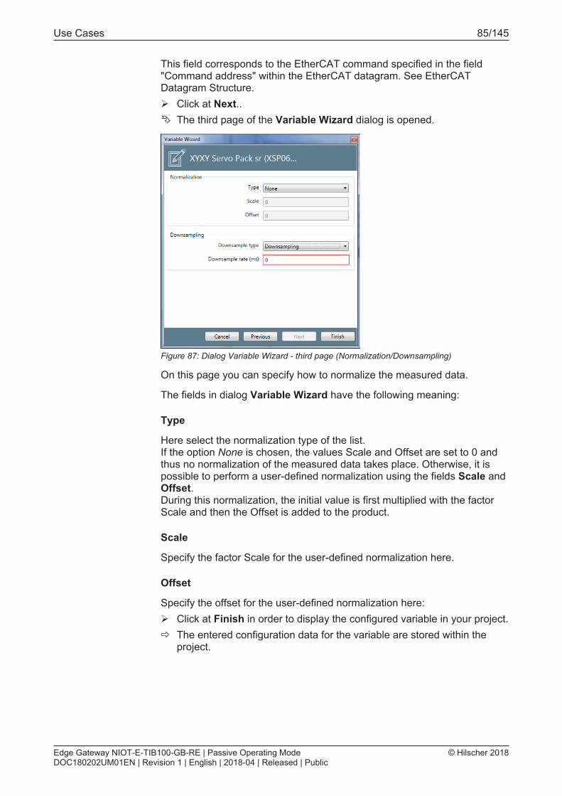
Use Cases 85/145
This field corresponds to the EtherCAT command specified in the field"Command address" within the EtherCAT datagram. See EtherCATDatagram Structure.Ø Click at Next..Ê The third page of the Variable Wizard dialog is opened.
Figure 87: Dialog Variable Wizard - third page (Normalization/Downsampling)
On this page you can specify how to normalize the measured data.
The fields in dialog Variable Wizard have the following meaning:
Type
Here select the normalization type of the list. If the option None is chosen, the values Scale and Offset are set to 0 andthus no normalization of the measured data takes place. Otherwise, it ispossible to perform a user-defined normalization using the fields Scale andOffset. During this normalization, the initial value is first multiplied with the factorScale and then the Offset is added to the product.
Scale
Specify the factor Scale for the user-defined normalization here.
Offset
Specify the offset for the user-defined normalization here:Ø Click at Finish in order to display the configured variable in your project.ð The entered configuration data for the variable are stored within the
project.
Edge Gateway NIOT-E-TIB100-GB-RE | Passive Operating ModeDOC180202UM01EN | Revision 1 | English | 2018-04 | Released | Public
© Hilscher 2018

Use Cases 86/145
Downsampling area
This area contains the specifications for performing downsampling in thePassive Fieldbus Configurator.
Selection list Downsample Type
The following options are provided by selection list Downsample Type.Option DescriptionSwitched off No downsampling of data occurs. All data values are acquired by
the network at their individual cycle.Only on change In this setting, acquired data will be transferred to the subsequent
processing only if changes occur.Downsampling If downsampling has been activated, the data are regularly sampled
after a defined time interval (the downsampling rate) and only thosesampled values are transferred to subsequent processing. Thistime interval is specified in input field Downsample Rate.
Input field Downsample-Rate
If the Downsample Type Downsampling has been selected, in this inputfield the downsample rate can be specified in units of milliseconds. Theallowed range of values extends from 1 to 1000 Milliseconds. See thefollowing figure.
Figure 88: Edit custom value filter – Downsampling-Type and -Rate
Edge Gateway NIOT-E-TIB100-GB-RE | Passive Operating ModeDOC180202UM01EN | Revision 1 | English | 2018-04 | Released | Public
© Hilscher 2018

Use Cases 87/145
4.4.6 Step 6 - Signal configurationIn order to activate a signal, proceed as follows:Ø Within the Passive Fieldbus Configurator, drag the signal from the
element list window into the window „Signal configuration“. To do so, check the signal(s) in window Element List and keep themouse button pressed while moving the mouse cursor to the window"Signal configuration". The figure below shows the state beforereleasing the mouse button. The red line is used only for clarification.
Figure 89: Signal configuration - during Drag&Drop
Ê If the mouse button is released, a new entry with the name of the signalis displayed in window „Signal configuration“.
Edge Gateway NIOT-E-TIB100-GB-RE | Passive Operating ModeDOC180202UM01EN | Revision 1 | English | 2018-04 | Released | Public
© Hilscher 2018

Use Cases 88/145
The entry with the name of the signals within the element list still remainsthere, but it is now protected against editing and erasure, i.e. the respectivecontext menu functions are grayed out and deactivated.Ø Configure the signals in the window Signal configuration of the
Passive Fieldbus Configurator. In window "Signal configuration", a newentry with the name of the signal is displayed. For each singleEtherCAT signal, you can also decide there, whether the acquired datashall be fetched from the Edge Gateway by OPC-UA or transferred intothe cloud by Node-RED.
Note:In order to reduce CPU time and memory consumption on the EdgeGateway only choose those methods for continuation of dataprocessing, which you really need in your specific application.
Edge Gateway NIOT-E-TIB100-GB-RE | Passive Operating ModeDOC180202UM01EN | Revision 1 | English | 2018-04 | Released | Public
© Hilscher 2018

Use Cases 89/145
4.4.7 Step 7 - Check Signals in the Live-Data ViewThis step is optional. However, it allows a quick and easy check whether asignal has been configured correctly.
The Live Data window consists of a display area on the left side, which canbe separated into some stacked parts (Buckets), and of an area on the rightside only containing a register card buckets that lists the current signalsand their assignment to these areas (Buckets)
Figure 90: Adding signals to the Live Data window
To view and record arbitrary signals of your choice within the live datawindow, start recording as follows:Ø Drag all signals intended to be viewed in the window Live Data one by
one with the mouse button pressed down from the element list into theright part Buckets of the Live Data window.
Ê The data acquisition within the Passive Fieldbus Configurator has beenstarted. In the Live View window you can watch the signals and tuneyour configuration if necessary.
Edge Gateway NIOT-E-TIB100-GB-RE | Passive Operating ModeDOC180202UM01EN | Revision 1 | English | 2018-04 | Released | Public
© Hilscher 2018

Use Cases 90/145
4.4.8 Step 8 - Storing the generated configuration file (EtherCAT)Ø Create a configuration file (i.e. project file) for your EtherCAT project
using the Passive Fieldbus Configurator. Store this file via Project >Savewithin the main menu before finishing working with the PassiveFieldbus Configurator .
ð You have now created a project file in the *.fbcfg format for theconfiguration of your EtherCAT network within the passive mode of theEdge Gateway. In section Uploading the project file to the EdgeGateway [} page 114] uploading of this file onto the Edge Gateway andactivating it there is described.
Edge Gateway NIOT-E-TIB100-GB-RE | Passive Operating ModeDOC180202UM01EN | Revision 1 | English | 2018-04 | Released | Public
© Hilscher 2018

Use Cases 91/145
4.5 Custom value filtersIn Passive Fieldbus Configurator you can work with custom-value filters(i.e. user- defined filters). This gives you the chance to detect and selectnearly arbitrary kinds of Ethernet frames.
A single criterion for frame selection can be specified using selection listType.
This opens many possibilities to define new criteria that are presentedwithin the following table:Frame selection method Typical examplesAccording to Ethernetcharacteristics
Only select frames with a certain Ethertype or VLAN-Tag Only select frames with a certain Source or Destination MAC
According to IPcharacteristics
Only select IP-Frames, IPv6-Frames, TCP-Frames, UDP-Frames Only select IP-Frames with a certain Source or Destination-IP-Address Only select TCP-Frames with a certain Source or Destination-Port
According to protocol-specific frame types
Only select EtherCAT-Frames Only selectPROFINET-Frames Only select frames with a certain Frame-ID Only select ICMP, LLDP, ARP, MRP or SNMP frames
Table 15: Criteria for frame selection
After the filter has been defined, it must finally be taken over into the signalconfiguration and thereby be activated.
This shall be illustrated in the following using an example:
Example - Definition of own filter conditions
As an example how to apply the Edge Gateway in the passive mode for thedetailed analysis of Ethernet frame data, we show you how to extract allpoll requests out of the data traffic within a Powerlink network which aresent from a Powerlink Controlled Node with address 1 as broadcast (i.e. toall participants).
This is accomplished by defining a filter for the Edge Gateway within thePassive Fieldbus Configurator which is able to select all Powerlink frameswith a certain Message Type (here Poll Request) and a certain sourceaddress (Controlled Node) and destination address (Broadcast).
This section describes how you can use custom-value filters to create aproject file enabling the Edge Gateway for passive data acquisition within aPowerlink network In this way you can learn valuable and importantconcepts how you can solve a manifold of similar problems usingthepassive data acquisition.
If the project file has been generated, it finally has to be uploaded to theEdge Gateway as described in Uploading the project file to the EdgeGateway [} page 114].
Edge Gateway NIOT-E-TIB100-GB-RE | Passive Operating ModeDOC180202UM01EN | Revision 1 | English | 2018-04 | Released | Public
© Hilscher 2018

Use Cases 92/145
The following prerequisites have to be met:1. The Passive Fieldbus Configurator must be installed. If this is not the
case, install it according to the installation instructions.2. The IP address of the Edge Gateway to be used must be known.
4.5.1 Step 1 - Start the Passive Fieldbus Configurator.Ø Start the Passive Fieldbus Configurator on your PC,
4.5.2 Step 2 - Creating an empty projectØ Build a new project within the Passive Fieldbus Configurator by
selecting the right buttonCreate->New in the introductory menu..
Ê The (still empty) GUI of the Passive Fieldbus Configurator is displayed.
Edge Gateway NIOT-E-TIB100-GB-RE | Passive Operating ModeDOC180202UM01EN | Revision 1 | English | 2018-04 | Released | Public
© Hilscher 2018

Use Cases 93/145
4.5.3 Step 3 - Adjust basic settings of the Passive Fieldbus Configurator.The Passive Fieldbus Configurator requires the following basic settings:· Setting of IP address· Setting ofSetting of network speed
To do so, proceed as follows:Ø Open the main menu. in order to do so, click at button Menu within the
side menu located at the right side.
Figure 91: Side menu
Ê The main menu is opened.
Figure 92: main menu - Register card "Views"
Edge Gateway NIOT-E-TIB100-GB-RE | Passive Operating ModeDOC180202UM01EN | Revision 1 | English | 2018-04 | Released | Public
© Hilscher 2018

Use Cases 94/145
Ø Select the register card Device assignment.
Figure 93: main menu - Register card "Device assignment"
In order to establish a connection with the Edge-Gateway, the IP address ofthe Edge-Gateway must be assigned to the software. This reqires theGateway being in the passive mode of operation. Proceed as follows:Ø Select the IP addresss of the Edge-Gateway to connect with from the
selection list IP Address in the device selection area. If this list is stillempty yet or the IP address of the Edge Gateway is missing in it,specify the IP address within the input field or click at the cog wheel
symbol at the right and specify the IP address in the dialog boxwhich will appear. This IP address must comply with the valid rules forspecifying IP adresses.
Ø Click at .Ê Finally, the connection with the according Edge Gateway has been
established.
As described in the following, you can check whether a connection to theEdge Gateway has been established:1. In the field Firmware Version the version number of the currently
installed firmware of the Edge Gateway is displayed.2. The status display in the right part of the lower status bar of the Passive
Fieldbus Configurator changes from blue indicating status Idle to yellowindicating status Stopped.
3. In the left part of the status bar now statistic information concerning theEthernet data traffic and zthe interface configuration are displayed.
4. The formerly grayed ot menu entry Connect is activated.
Edge Gateway NIOT-E-TIB100-GB-RE | Passive Operating ModeDOC180202UM01EN | Revision 1 | English | 2018-04 | Released | Public
© Hilscher 2018

Use Cases 95/145
Otherwise the following error message will appear:
Figure 94: Error message "The connection to the device was not possible"
The most probable cause of this error message is the Edge Gateway notbeing in the configuration mode of the passive mode of operation!
Note:For more information concerning the solution of this problem seesection Error handling [} page 117].
4.5.4 Step 4 - Define filter conditions for custom-value filtersThe editor allows logic operations connecting multiple criteria.
The following kinds of logic operations are available.· Void (no logic operation, only a single filter value is used)
· and(AND operation)
· Or(OR conjunction)
· not(Negation, only a single filter value is used)
· xorExclusive-OR-conjunction)
Edge Gateway NIOT-E-TIB100-GB-RE | Passive Operating ModeDOC180202UM01EN | Revision 1 | English | 2018-04 | Released | Public
© Hilscher 2018

Use Cases 96/145
To define the filter required for the example totally four filter criteria whichare related to one another are used.· The first filter criterion is used to detect whether the current frame is a
Powerlink frame. In order to detect Powerlink frames their Ethertype canbe used. In general, Powerlink frames have the Ethertype 0x88AB. Sothe Ethertype of the frame to be tested must be checked for equalitywith the hexadecimal value 0x88AB.
· The second filter criterion is used to check whether a poll request ispresent.A check whether the Message Type located in thew byte withoffset 14 within the Ethernet frame equals 4 is required
· The third filter criterion is used for detection of broadcasts. In order todo so, it must be checked whether the Destination-IP address located atthe byte with offset 15 within the Ethernet frame equals 255.
· The fourth filter criterion is used to check whether the frame originatesfrom the Controlled Node (Slave) with the address 1 stammt. To do so,the Source-IP address located at the byte with offset 16 within theEthernet Frame must be checked whether it equals 1.
Figure 95: Assignment of the four filter criteria to the Wireshark Trace
Edge Gateway NIOT-E-TIB100-GB-RE | Passive Operating ModeDOC180202UM01EN | Revision 1 | English | 2018-04 | Released | Public
© Hilscher 2018

Use Cases 97/145
This is accomplished by defining a filter for the Edge Gateway within thePassive Fieldbus Configurator which is able to select all Powerlink frameswith a certain Message Type (here Poll Request) and a certain sourceaddress (Controlled Node) and destination address (Broadcast).Ø Open the dialog Add custom value filter using the context menu.Ø At Filtername specify the Filtername, here Detect Powerlink frames.Ê Now the dialog looks as follows.
Figure 96: Specify filter name
Ø Click at Next..Ø In order to combine to criteria with a AND operation, open the selection
list and select the option And for the relation as shown in the figure.
Figure 97: Custom-value filters - Selection of logical function
Edge Gateway NIOT-E-TIB100-GB-RE | Passive Operating ModeDOC180202UM01EN | Revision 1 | English | 2018-04 | Released | Public
© Hilscher 2018

Use Cases 98/145
For an And-operation, you need (at least) two filter criteria.Ø For specifying the first filter criterion Ethertype equals 0x88AB click at
the symbol .Ê A box for specifying the filter criterion appears.
Figure 98: Custom value filters
Ø Then select the entry Ethertype directly below Ethernet within theselection list Type, see figure:
Figure 99: Custom value filters - Selection of Ethertype for recognition of Powerlinkframes
Edge Gateway NIOT-E-TIB100-GB-RE | Passive Operating ModeDOC180202UM01EN | Revision 1 | English | 2018-04 | Released | Public
© Hilscher 2018

Use Cases 99/145
Ø At operator select equals in order to check for existence of Powerlinkframes.
Figure 100: Custom value filters
Ø Specify the hexadecimal value 0x88AB within the right of both fieldsbelow Value.
ð The first filter condition Ethertype equals 0x88AB has now beenspecified completely and is displayed within a box.
Figure 101: Custom value filters - first filter condition complete (including Wireshark trace)
Ø Here, you may write an optional comment into the input field Comment,for instance Detection of Powerlink frames.
Edge Gateway NIOT-E-TIB100-GB-RE | Passive Operating ModeDOC180202UM01EN | Revision 1 | English | 2018-04 | Released | Public
© Hilscher 2018

Use Cases 100/145
Now the second filter criterion must be specified.Ø In order to specify the second filter criterion Byte at Offset 14 of the
Ethernet Frames equals 4, again click at the Symbol .Ê A second box for specifying a filter criterion appears.
Figure 102: Specifying the second filter criterion - Entering the filter condition
Ø Below type select User-definedt uint8.
Figure 103: Specifying the second filter criterion - Selection of User-defined uint8
Edge Gateway NIOT-E-TIB100-GB-RE | Passive Operating ModeDOC180202UM01EN | Revision 1 | English | 2018-04 | Released | Public
© Hilscher 2018

Use Cases 101/145
Ê After the selection, the dialog looks as follows:
Figure 104: Specifying the second filter criterion -Afdter selection of User-defined uint8
Ø At operator the option equals must be selected - this is also the defaultoption.
Ø For Value there are two input fields. the left of these is dedicated fordecimal inputs, the right one for hexadecimal inputs. Specify the value 4within the left (decimal) input field.
Figure 105: Specifying the second filter criterion - Input of the value of Ethernet frame,byte offset 14
Ê As soon as a valid value has been entered, the red frames around themandatory input fields Value are displayed in grey.
Edge Gateway NIOT-E-TIB100-GB-RE | Passive Operating ModeDOC180202UM01EN | Revision 1 | English | 2018-04 | Released | Public
© Hilscher 2018

Use Cases 102/145
Ø Specify the offset of the byte within the Ethernet-Frameto be used forcomparison, here the byte with offset 14.
Figure 106: Specifying the second filter criterion - Input of the offset
Ø You may write an additional comment into the input field Comment, forinstance Destination broadcast.
ð Now the dialog looks as follows.
Figure 107: Specifying the second filter criterion -
Edge Gateway NIOT-E-TIB100-GB-RE | Passive Operating ModeDOC180202UM01EN | Revision 1 | English | 2018-04 | Released | Public
© Hilscher 2018

Use Cases 103/145
Now the third filter criterion must be specified.Ø In order to specify the third filter criterion Byte at Offset 15 of the
Ethernet Frames equals 255, again click at the Symbol .Ê Another box for specifying the filter criterion appears.
Figure 108: Specifying the third filter criterion - Entering the third filter condition
Ø Below type select User-definedt uint8.
Figure 109: Specifying the second filter criterion - Selection of User-defined uint8
Edge Gateway NIOT-E-TIB100-GB-RE | Passive Operating ModeDOC180202UM01EN | Revision 1 | English | 2018-04 | Released | Public
© Hilscher 2018

Use Cases 104/145
Ê After the selection, the dialog looks as follows:
Figure 110: Specifying the third filter criterion -After selection of User-defined uint8
Ø At operator the option equals must be selected - this is also the defaultoption.
Ø For Value there are two input fields. The left of these is dedicated fordecimal inputs, the right one for hexadecimal inputs.Enter the value 255in the left (decimal) input field.
Figure 111: Specifying the third filter criterion - Input of the value of Ethernet frame, byteoffset 15
Ê As soon as a valid value has been entered, the red frames around themandatory input fields Value are displayed in grey.
Edge Gateway NIOT-E-TIB100-GB-RE | Passive Operating ModeDOC180202UM01EN | Revision 1 | English | 2018-04 | Released | Public
© Hilscher 2018

Use Cases 105/145
Ø Specify the offset of the byte within the Ethernet-Frameto be used forcomparison, here the byte with offset 15.
Figure 112: Specifying the third filter criterion - Input of the offset
Ø Here, you may write an optional comment into the input field Comment,for instance Message type: Poll response.
ð Now the dialog looks like this.
Figure 113: Specifying the third filter criterion (with Wireshark trace)
Edge Gateway NIOT-E-TIB100-GB-RE | Passive Operating ModeDOC180202UM01EN | Revision 1 | English | 2018-04 | Released | Public
© Hilscher 2018

Use Cases 106/145
Now the fourth filter criterion must be specified.Ø In order to specify the third filter criterion Byte at Offset 16 of the
Ethernet Frames equals 1, again click at the Symbol .Ê Another box for specifying a filter criterion appears.
Figure 114: Specifying the fourth filter criterion - Entering the filter condition
Ø Below type select User-definedt uint8.
Figure 115: Specifying the fourth filter criterion - Selection of User-defined uint8
Edge Gateway NIOT-E-TIB100-GB-RE | Passive Operating ModeDOC180202UM01EN | Revision 1 | English | 2018-04 | Released | Public
© Hilscher 2018

Use Cases 107/145
Ê After the selection, the dialog looks as follows:
Figure 116: Specifying the fourth filter criterion - After selection of User-defined uint8
Ø At operator the option equals must be selected - this is also the defaultoption.
Ø For Value there are two input fields. the left of these is dedicated fordecimal inputs, the right one for hexadecimal inputs.
Ê As soon as a valid value has been entered, the red frames around themandatory input fields Value are displayed in grey.
Ø Specify the offset of the byte within the Ethernet-Frame to be used forcomparison, here the byte with offset 16.
Ø Here, you may write an optional comment into the input field Comment,for instance Source 1 (Controlled Node.
Edge Gateway NIOT-E-TIB100-GB-RE | Passive Operating ModeDOC180202UM01EN | Revision 1 | English | 2018-04 | Released | Public
© Hilscher 2018

Use Cases 108/145
ð Now the dialog looks as follows.
Figure 117: Specifying the flurth filter criterion - (with Wireshark trace)
If you want to analyze the frames more precisely, you may view these usingthe Frame Quicktesters.
To open the Frame Quicktester, click at the small arrow right of the textOpen Frame Quicktester un the upper right corner of the dialog. Thedialog is then enlarged by the area of the Frame Quicktester. The controlsof the Frame Quicktester are self-explaining if clicking at the i-signs within acircle adjacent to these controls. When doing so, additional explanatorytexts about the controls are displayed.
Edge Gateway NIOT-E-TIB100-GB-RE | Passive Operating ModeDOC180202UM01EN | Revision 1 | English | 2018-04 | Released | Public
© Hilscher 2018

Use Cases 109/145
Ø Click at Next.Ê The third page of the dialog Edit custom-vslue filters is opened.
Figure 118: Custom-value filters - Specifications for extracting the values out of the acquiredframes
On this page specifications for the extraction of data values from selectedincoming Ethernet frames can be made.
I.e. here it can be defined how a certain value is assigned to each incomingEthernet-Frame , which can subsequently be displayed in the Live View orpostprocessed by OPC UA or Node-RED, for instance.
The reaction to incoming Ethernet frames of a certain selected type can bedefined using the following approaches to extraction:Method Line of actionEvent extraction Only an event to be counted occurs indicating the occuremce of the
selected frame type.An explicite assignment of a value to the framedoes not happen. For instance, this approach allows counting thenumber of incoming frames fulfilling a certain filter condition.
Value extraction Each incoming Ethernet frame is assigned a certain value byanalysis of the frame contents using defined rules.
Table 16: Custom-value Filters – Approaches to extraction
Edge Gateway NIOT-E-TIB100-GB-RE | Passive Operating ModeDOC180202UM01EN | Revision 1 | English | 2018-04 | Released | Public
© Hilscher 2018

Use Cases 110/145
In order to define these rules for the value extraction, the followingparameters can be specified for this approach:Parameter MeaningVariable type The variable type of the value to be determined
The selection possibilities include the type „Boolean“, various bittypes and string types, unsigned and signed integer types andfloating-point types.
Unit The unit assigned to the value to be determined (optionalspecification)
Byte order This parameter decides whether the byte order shall be swapped ornot.
Length in bits The length of the value to be determined, specified as number of bits.The extractionposition.
This specification allows to decide from which position within theframe the byte offset is counted. The possible options are:
· Ethernetframe
· Ethernet payload
· TCP payload
· UDP payloadByte offset The byte offset. It specifies the first byte to be extracted relative to
the extraction position, i.e.how many bytes after the start (or beforethe end) of the extraction position the extraction begins
Bit offset The bit offset. It specifies how many bitsafter the start (or before theend) of the first byte to be evaluatted within the Ethernet frame theextraction begins. The range of values extends from 0 to 7.
Counting directionfor offset
Indicates the direction into which the byte offset works: Bytes afterthe beginning or before the end of the extraction position. Thepossible options are:
· From the beginning
· From the endTable 17: Custom-value Filters – Parameters for extraction and their meaning
Ø Click at Next.Ê The fourth page of the dialog Edit custom-value filters is opened now:
Figure 119: Custom-value filters – Specification for normalization of acquired data
Edge Gateway NIOT-E-TIB100-GB-RE | Passive Operating ModeDOC180202UM01EN | Revision 1 | English | 2018-04 | Released | Public
© Hilscher 2018

Use Cases 111/145
On this page you can enter specifications for normalization of the acquireddata values. During normalization the data value is multiplied with a ficxedfactor and then a fixed offset is added to the product. Whether thisclculation occurs and which values the scale factor and the offset shouldhave, can be specified on this dialog page.
The fields within the dialog Edit custom-value filter have the followingmeaning:
Type
Select the normalization type of the list here. If the option None is chosen, the values Scale and Offset are set to 0 andthus no normalization of the measured data takes place. Otherwise, it ispossible to perform a custom-defined normalization based on the fieldsFactor and Offset.During this normalization, the original value is first multiplied with thespecified scale factor and then the offset is added to the intermediateresult.
Scale
Specify the factor Scale for the user-defined normalization here:
Offset
Specify the offset for the user-defined normalization here:Ø Click at Finish in order to display the configured variable in your project.ð The entered configuration data for the variable are stored within the
project.Ø Click at Finish.ð The custom-value filter just having been defined is stored.
Edge Gateway NIOT-E-TIB100-GB-RE | Passive Operating ModeDOC180202UM01EN | Revision 1 | English | 2018-04 | Released | Public
© Hilscher 2018

Use Cases 112/145
4.5.5 Step 5 - Signal configurationTo activate the filter, proceed as follows:Ø Within the Passive Fieldbus Configurator, drag the signal from the
element list window into the window „Signal configuration“.ð In the window Signal configuration of the Passive Fieldbus
Configurator, a new entry with the name of the filter (in the exampleDetect Powerlink-Framesis displayed. By checking By checking thecheckbox, you can separately determine for each single filter, whetherthe acquired data shall be fetched from the Edge Gateway by OPC-UAor transferred into the cloud by Node-RED. whether the acquired datashall be fetched from the Edge Gateway by OPC UA or made availablewithin Node-RED.
ð The entry with the name of the custom-value filter within the element liststill remains there, but now it is protected against editing and erasure,i.e. the respective context menu functions are grayed out anddeactivated.
Figure 120: Window "Signal configuration" of the Passive Fieldbus Configurator.
ð Finally, the configuration of the custom-value filters has beencompleted.
Note:In order to reduce CPU time and memory consumption on the EdgeGateway only choose those methods for continuation of dataprocessing, which you really need in your specific application.
Edge Gateway NIOT-E-TIB100-GB-RE | Passive Operating ModeDOC180202UM01EN | Revision 1 | English | 2018-04 | Released | Public
© Hilscher 2018

Use Cases 113/145
4.5.6 Step 6 - Check Signals in the Live-Data ViewThis step is optional. Viewing signals within a live-data window isrecommended if you want to check whether a specific signal has beenconfigured correctly .
Proceed as follows:Ø Drag all signals intended to be viewed in the window Live Data one by
one with the mouse button pressed down from the element list into theright part Buckets of the Live Data window.
Ê The data acquisition within the Passive Fieldbus Configurator has beenstarted. In the Live View window you can watch the signals and tuneyour configuration if necessary.
4.5.7 Step 7 - Storing the generated configuration fileØ Create a configuration file (i.e. project file) for your project using the
Passive Fieldbus Configurator. Store this file via Project > Save withinthe main menu before finishing working with the Passive FieldbusConfigurator .
ð You have now created a project file for the configuration of your networkwithin the passive mode of the Edge Gateway. In section Uploading theproject file to the Edge Gateway [} page 114] is described, how you canupload this file to the Edge Gateway and activate it there.
Edge Gateway NIOT-E-TIB100-GB-RE | Passive Operating ModeDOC180202UM01EN | Revision 1 | English | 2018-04 | Released | Public
© Hilscher 2018
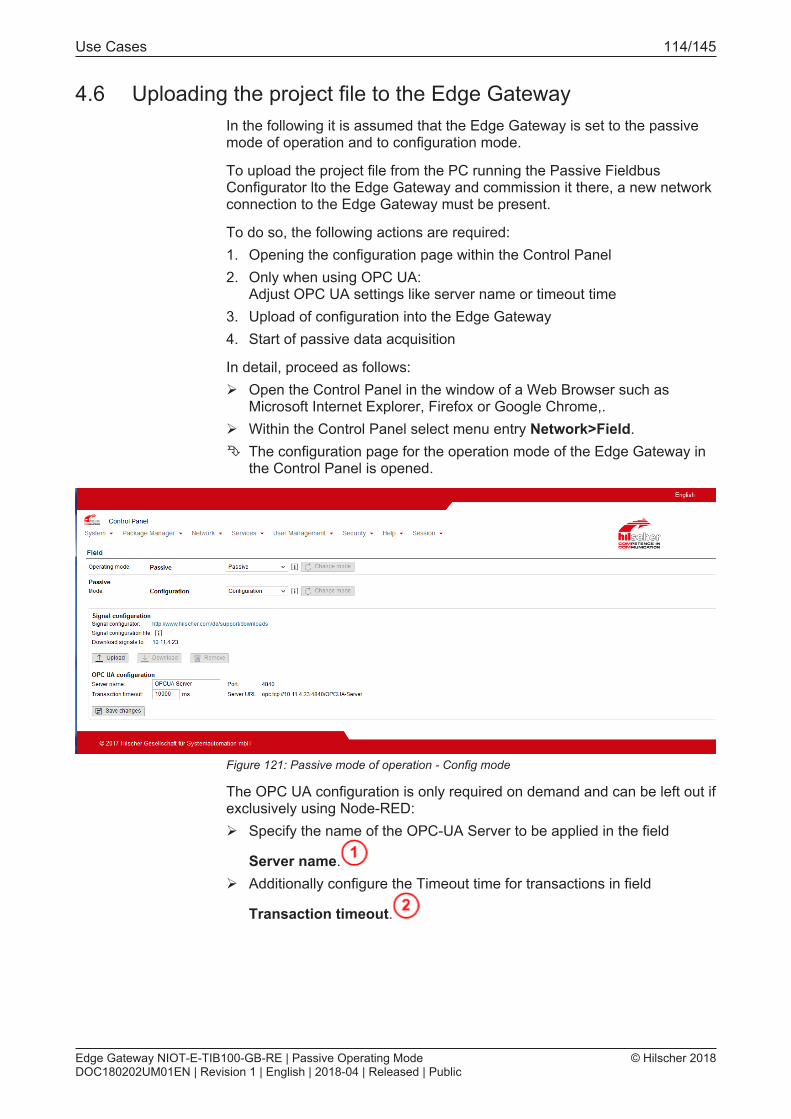
Use Cases 114/145
4.6 Uploading the project file to the Edge GatewayIn the following it is assumed that the Edge Gateway is set to the passivemode of operation and to configuration mode.
To upload the project file from the PC running the Passive FieldbusConfigurator lto the Edge Gateway and commission it there, a new networkconnection to the Edge Gateway must be present.
To do so, the following actions are required:1. Opening the configuration page within the Control Panel2. Only when using OPC UA:
Adjust OPC UA settings like server name or timeout time3. Upload of configuration into the Edge Gateway4. Start of passive data acquisition
In detail, proceed as follows:Ø Open the Control Panel in the window of a Web Browser such as
Microsoft Internet Explorer, Firefox or Google Chrome,.Ø Within the Control Panel select menu entry Network>Field.Ê The configuration page for the operation mode of the Edge Gateway in
the Control Panel is opened.
Figure 121: Passive mode of operation - Config mode
The OPC UA configuration is only required on demand and can be left out ifexclusively using Node-RED:Ø Specify the name of the OPC-UA Server to be applied in the field
Server name.Ø Additionally configure the Timeout time for transactions in field
Transaction timeout.
Edge Gateway NIOT-E-TIB100-GB-RE | Passive Operating ModeDOC180202UM01EN | Revision 1 | English | 2018-04 | Released | Public
© Hilscher 2018

Use Cases 115/145
Figure 122: OPC UA configuration (Figure only shows a part)
Ø Confirm the changes in the OPC UA configuration by clicking at "Savechanges".
Ê All specifications required for the configuration of the Edge Gatewayhave now been entered completely. In order to make the signalconfiguration file effective, it has to be transferred to the Edge Gateway.
Ø To transfer the selected configuration into the Edge Gateway, click atUpload.
Figure 123: Button "Upload" in the signal configuration area of the configuration page inthe control panel
Ê A dialog for selcting the project file is displayed.Ø Select the project file generated by the Passive Fieldbus Configurator
within previous step (File type *.fbcfg)Ê After your selection the project file is transferred to the Edge Gateway.
However, the data acquisition has not yet been started.
Edge Gateway NIOT-E-TIB100-GB-RE | Passive Operating ModeDOC180202UM01EN | Revision 1 | English | 2018-04 | Released | Public
© Hilscher 2018

Use Cases 116/145
Ø To activate the data acquisition, switch to the Operational Mode.
Figure 124: Switching to operational mode in passive mode of operation
Ê A dialog window appears and informs about the OPC UA Server beingactivated and no further changes in configuration being applicable.
Figure 125: Dialog window displayed when switching into the Operational Mode of thePassive Mode.
Ø At the confirmation prompt answer with Yes.ð The OPC-UA Server and the „passive fieldbus“ node of Node-RED are
restarted. The passive data acquisition according to the configuredsettings and the currently active Node-RED flow begins.
The configured signals are then continued to be processed according to thesetting in window „Signalkonfiguration“ :· Any arbitrary OPC UA client can access all signals for which the
checkbox OPC UA has been checked in the signal configuration. Alsosee OPC UA Client reads process data from EdgeGateway [} page 122]
· The passivefieldbus node can access all signals for which thecheckbox Node-Node-RED has been checked in the signalconfiguration, for instance in order to transfer data to the cloud..See Node-RED transfers process data into the Cloud [} page 127].
Edge Gateway NIOT-E-TIB100-GB-RE | Passive Operating ModeDOC180202UM01EN | Revision 1 | English | 2018-04 | Released | Public
© Hilscher 2018

Use Cases 117/145
4.7 Error handlingThe following error situations may occur when working with the assiveFieldbus Configurator:
Error message "No connection to the Edge Gateway" at assignmentof IP address.
If an error message that no connection to the Edge Gateway could beestablished is received during the assignment of the IP address, then checkthe following topics and repeat the assignment.
1. Is the Edge Gateway switched on and is it connected to the IT- and OT-networks?
2. Has the Edge Gate3way been switched to the passive mode ofoperation?
3. Has the Edge Gateway been switched to configuration mode. In mode Operation no assignment is possible.
4. Has the correct IP address been entered?5. Is the used driver version of the Passive Fieldbus Configurators the
most current one?
If question (2) or question (3) have been answered with "No", proceed asfollows in order to solve the problem:Ø Invoke the Control Panel and select the menu Network > Field there.Ø Select the passive mode of operation at Operating mode.Ø At Passive Mode select „Configuration“.Ø Repeat the assignment.ð Now the assignment of the IP address should beperformed
successfully.
Edge Gateway NIOT-E-TIB100-GB-RE | Passive Operating ModeDOC180202UM01EN | Revision 1 | English | 2018-04 | Released | Public
© Hilscher 2018

Use Cases 118/145
Error message during loading the GSDML file.
If an error occurs during reading the GSDML file, the following errormessage appears:
Figure 126: Error message "Parsing error in..."
In this case check the GSDML file for correctness and evaluate theadditional information concerning the error which might be shown in theoutput window of the Passive Fieldbus Configurator.
Error message when loading the ENI file
If an error occurs during reading the ENI file, the following error messageappears:
Figure 127: Error message "failed to load ENI file"
In this case check the ENI file for correctness and evaluate the additionalinformation concerning the error which might be shown in the outputwindow of the Passive Fieldbus Configurator.
Edge Gateway NIOT-E-TIB100-GB-RE | Passive Operating ModeDOC180202UM01EN | Revision 1 | English | 2018-04 | Released | Public
© Hilscher 2018

Use Cases 119/145
Error message: GSDML file already exists
If the follwoing message appears during reading in the PROFINET devicedescription file:
Figure 128: GSDML file already exists
The selected GSDML file is already loaded.
Error message in order to prevent overwriting existing elements
If the following message appears when reading the EtherCAT devicedecription file:
Figure 129: Overwriting of existing elements
An EtherCAT network information file (ENI file) has already been loaded.· If you click at "Ja", this already existing ENI file will be overwritten by the
selected ENI file.· If you click at "Nein", the currently loaded ENI file will be preserved.
Edge Gateway NIOT-E-TIB100-GB-RE | Passive Operating ModeDOC180202UM01EN | Revision 1 | English | 2018-04 | Released | Public
© Hilscher 2018

Use Cases 120/145
Error message if a module with same slot number is already present
If the following message should occur when creating PROFINET modules:
Figure 130: A module with same slot number already exists!
Check, whether the correct slot number is in use as a slot with the specifiednumber already exists.
Error message if a module with same subslot number is alreadypresent
If the following message should occur when creating PROFINETsubmodules:
Figure 131: A submodule with same subslot number already exists!
Check, whether the correct subslot number is in use as a subslot with thespecified number already exists.
Edge Gateway NIOT-E-TIB100-GB-RE | Passive Operating ModeDOC180202UM01EN | Revision 1 | English | 2018-04 | Released | Public
© Hilscher 2018

Use Cases 121/145
Process data invisible when importing an ENI file generated byCodesys
When exporting ENI files from Codesys, it may happen that the exportedENI file does not match the actual network configuration. Specifically, otherlogical bus addresses are exported into the ENI file, than the ones actuallyused by the Codesys PLC. Possibly incorrect address assignments for yourvariables can be manually edited in netANALYZER Scope. Thus, theincorrect address can be replaced by the correct address (the changes arestored in the .fbcfg project and are only necessary once).
Figure 132: Wireshark example for Codesys ENI-Import
You can observe which address the Codesys PLC actually uses during realnetwork communication by getting the addresses from a Wireshark trace.
In the following it is assumed that the Edge Gateway is set to the passivemode of operation and to configuration mode.
To upload the project file from the PC running the Passive FieldbusConfigurator lto the Edge Gateway and commission it there, a new networkconnection to the Edge Gateway must be present.
Edge Gateway NIOT-E-TIB100-GB-RE | Passive Operating ModeDOC180202UM01EN | Revision 1 | English | 2018-04 | Released | Public
© Hilscher 2018
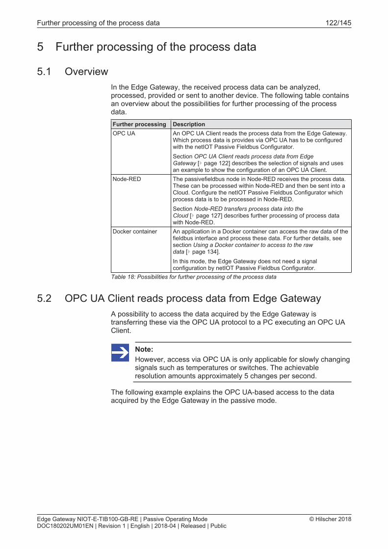
Further processing of the process data 122/145
5 Further processing of the process data
5.1 OverviewIn the Edge Gateway, the received process data can be analyzed,processed, provided or sent to another device. The following table containsan overview about the possibilities for further processing of the processdata.Further processing DescriptionOPC UA An OPC UA Client reads the process data from the Edge Gateway.
Which process data is provides via OPC UA has to be configuredwith the netIOT Passive Fieldbus Configurator.Section OPC UA Client reads process data from EdgeGateway [} page 122] describes the selection of signals and usesan example to show the configuration of an OPC UA Client.
Node-RED The passivefieldbus node in Node-RED receives the process data.These can be processed within Node-RED and then be sent into aCloud. Configure the netIOT Passive Fieldbus Configurator whichprocess data is to be processed in Node-RED.Section Node-RED transfers process data into theCloud [} page 127] describes further processing of process datawith Node-RED.
Docker container An application in a Docker container can access the raw data of thefieldbus interface and process these data. For further details, seesection Using a Docker container to access to the rawdata [} page 134].In this mode, the Edge Gateway does not need a signalconfiguration by netIOT Passive Fieldbus Configurator.
Table 18: Possibilities for further processing of the process data
5.2 OPC UA Client reads process data from Edge GatewayA possibility to access the data acquired by the Edge Gateway istransferring these via the OPC UA protocol to a PC executing an OPC UAClient.
Note:However, access via OPC UA is only applicable for slowly changingsignals such as temperatures or switches. The achievableresolution amounts approximately 5 changes per second.
The following example explains the OPC UA-based access to the dataacquired by the Edge Gateway in the passive mode.
Edge Gateway NIOT-E-TIB100-GB-RE | Passive Operating ModeDOC180202UM01EN | Revision 1 | English | 2018-04 | Released | Public
© Hilscher 2018

Further processing of the process data 123/145
5.2.1 Selecting signals for OPC UAYou have to select the signals for OPC UA with the netIOT PassiveFieldbus Configurator. Check OPC UA in the Signal Configurationwindow for signals that the OPC UA Server in the Edge Gateway shouldprovide.
Figure 133: Selecting signals for OPC UA
Edge Gateway NIOT-E-TIB100-GB-RE | Passive Operating ModeDOC180202UM01EN | Revision 1 | English | 2018-04 | Released | Public
© Hilscher 2018

Further processing of the process data 124/145
5.2.2 Example: Access to the Edge Gateway over OPC UA using theClient UA Expert
Prerequisites
This example uses the OPC UA-Client UA Expert from Unified Automation(http://www.unified-automation.com). Fulfill the following conditions inorder to access the current data of the Edge Gateway via the UA Expert:1. UA Expert must have been installed.2. The Edge Gateway is currently in the passive mode of operation and
the mode Operational is active.
Approach
Proceed as follows:Ø Start the UA Expert.
Figure 134: Intro screen of OPC UA Client UA Expert
Edge Gateway NIOT-E-TIB100-GB-RE | Passive Operating ModeDOC180202UM01EN | Revision 1 | English | 2018-04 | Released | Public
© Hilscher 2018

Further processing of the process data 125/145
Ø Specify the Server URL of the OPC UA Server of the Edge Gateway. InUA Expert, open the context menu of entry Project>Servers in windowProject using the right mouse button, usually the left upper window.
Figure 135: Context menu of the UA Expert
Ø Select entry Add.Ê The window Add Server is opened in UA Expert.
Figure 136: Dialog Add Server in UA Expert
Ø Click at the entry Double click to Add Server below CustomDiscovery.
Ê The dialog box Enter Url is opened:
Figure 137: Dialog box Enter Url in UA Expert
Edge Gateway NIOT-E-TIB100-GB-RE | Passive Operating ModeDOC180202UM01EN | Revision 1 | English | 2018-04 | Released | Public
© Hilscher 2018

Further processing of the process data 126/145
Ø The Server URL to be entered into this dialog box can be taken from thepage Network>Field of the Control Panel. This URL is structured asfollows:opc.tcp://<IP-Address>:<OPC UA Port>
Ø In order to close the dialog box, click at Ok.Ê The dialog box is closed.Ø In order to close the window Add Server click at Ok.ð The window is closed. The window Address Space displays an object-
oriented data model within a tree-structure. There, you find theconfiguration tree of the Passive Fieldbus Configurator below entryRoot>Objects>passivefieldbus. Below this entry, all process data arelisted which have been taken over into the signal configuration withinthe Passive Fieldbus Configurator and for which the respectivecheckbox OPC UA has been checked.
ð In the window Data Access View of the UA Expert, the process dataare displayed in „live mode“ and regularly updated.
If you should receive the error message Bad Certification Trust , thismessage is caused by the use of the self-signed certificate stored within theEdge Gateway in its state of delivery.
You have two possibilities to react:1. Recommended solution: Install an own certificate instead of the self-
signed one from the delivery state of the Edge Gateway.2. Alternative solution:You can also just ignore the message Bad
Certification Trust. Although the message text states the opposite, thereis really no danger in using the self-signed cerificate provided byHilscher.
Note:Concerning this topic read the notes at the following link Secureconnection.
Edge Gateway NIOT-E-TIB100-GB-RE | Passive Operating ModeDOC180202UM01EN | Revision 1 | English | 2018-04 | Released | Public
© Hilscher 2018

Further processing of the process data 127/145
5.3 Node-RED transfers process data into the CloudThe acquired data can also be transferred to Node-RED instead of an OPCUA-Client. By its flexibility, Node-RED offers a multitude of possibilities forpost-processing the acquired data.
Note:The access via Node-RED allows processing highly dynamicprocess values, for instance from processes in drive technology, aseach value is acquired with a precise time-stamp according to thecurrent cycle.
When designing the Node-RED flow, use the node passivefieldbus inorder to access the data.
5.3.1 Selecting signals for Node-REDYou have to select the signals for Node-RED with the netIOT PassiveFieldbus Configurator. Check Node-RED in the Signal Configurationwindow for signals for further processing in Node-RED.
Figure 138: Selecting signals for Node-RED
Edge Gateway NIOT-E-TIB100-GB-RE | Passive Operating ModeDOC180202UM01EN | Revision 1 | English | 2018-04 | Released | Public
© Hilscher 2018

Further processing of the process data 128/145
5.3.2 The input node "passivefieldbus"The input node "passivefieldbus" is used in a similar way as thefieldbus input node "fieldbus". It allows you to receive data from theReal-Time Ethernet network in the passive mode of the Edge Gateway.The following condition must be fulfilled: These data to be received must bechecked within the signal configuration.
The input node "passivefieldbus" just like the Edge Gateway in thepassive mode only works in one direction: it only delivers data, but it cannotreceive any data.
Configuration
Figure 139: Edit passive fieldbus node
At the configuration of the node passivefieldbus, the followingparameters must be specified:Parameter Default MeaningName passive
fb1Specify the name of the passivefieldbus node here.
Updateinterval
1000 Specify the time interval of the passivefieldbus node inunits of the milliseconds here after which thepassivefieldbus node is read out.
Table 19: Parameters for the configuration of node passivefieldbus:
Considerations concerning the update interval
The minimum applicable value amounts 200 ms. We recommend to use avalue of about some seconds in order to avoid a frame buffer overflow ofthe Edge Gateway and consequential data drops.
Edge Gateway NIOT-E-TIB100-GB-RE | Passive Operating ModeDOC180202UM01EN | Revision 1 | English | 2018-04 | Released | Public
© Hilscher 2018

Further processing of the process data 129/145
Example Access to the passivefieldbus node via the debug node
The following example shows how you can access the data delivered bythe input node "passivefieldbus" . It uses the input nodepassivefieldbus together with a debug node.
The input node passivefieldbus has to receive data from the Edge-Gateway. The debug node is used to display these data in the register cardDebug in the edge bar of Node-RED.
Prerequisites
The following prerequisites have to be met:1. A connection to the Edge Gateway has been established (see section
Using the web browser to establish a connection with the EdgeGateway):
2. The Node-RED workspace is open.
Step-by-step instructions
Reproduce this example as follows in Node-RED:
1. Insert input node "passivefieldbus" within the Node-RED workspacearea:Ø Pull an input node "passivefieldbus" from the node library and
insert it into the worksheet.Ê The input node passivefieldbus is displayed.
Ê
2. Open bar at the right edgeØ Open the bar at the right edge with the key combination Ctrl+Space
or via the Node-RED menu View>Show SidebarØ Click at register card Info of the bar at the right edgeØ Click at the input node passivefieldbus in order to display its properties
and function description in register card Info.
Edge Gateway NIOT-E-TIB100-GB-RE | Passive Operating ModeDOC180202UM01EN | Revision 1 | English | 2018-04 | Released | Public
© Hilscher 2018

Further processing of the process data 130/145
3. Edit input node "passivefieldbus":Ø Open the edit window by double-clicking at the input node
passivefieldbus.Ê The edit window for specifying the parameters is displayed.
Figure 140: Edit window for specifying the parameters.
4. Specify the nameØ Specify a node name for Name. The default name is passive fb1.
5. Specify the update intervalØ Specify the desired update interrval here. The default value amounts to
1000 ms.
6. Complete fieldbus input nodeØ Click at Done.Ê The configuration of the input node passivefieldbus is now
completed.
7. Insert debug nodeØ Pull a debug node out of the node library and insert it to the worksheet.
8. Connect nodesØ Connect the fieldbus with the "Debug" node by dragging a line from the
output connector of the fieldbus node to theinput connector of the debugnode.
DeployØ Click at Deploy in order to transfer the nodes still only existing in the
editor to the Edge Gateway and to activate those there.
Edge Gateway NIOT-E-TIB100-GB-RE | Passive Operating ModeDOC180202UM01EN | Revision 1 | English | 2018-04 | Released | Public
© Hilscher 2018

Further processing of the process data 131/145
ð The data flow within the Edge Gateway is activated.
Every time the update interval passes again, the input node"passivefieldbus" periodically delivers new data, the variablemsg.payload of the debug node is updated with new values. You candisplay these in register card Debug of the bar at the right edge of theNode-RED window.
5.3.3 Structure of the data delivered by the input nodeThe data delivered from the input node to the debug node (Variablemsg.payload) are delivered as an array of process variables.
Each process variable i.e. each element of this array· represents an object in JSON notation· corresponds to a checked variable of the Node-RED signal
configuration (see Step 6 - Signal configuration [} page 37]).
In the following, two objects are shown as example:[{"valueList": [{"ts": "1508346006127776395","val": 104,"state": "valid"},{"ts": "1508346006129766435","val": 56,"state": "valid"},{"ts": "1508346006131767355","val": 104,"state": "valid"},{"ts": "1508346006133801555","val": 32,"state": "valid"}],"name": "et200sp.AQ 4xU/I ST V1.0.AQ 4xU/I ST V1.0.O-channel 0","datatype": "INTEGER16"},{"valueList": [{"ts": "1508346006127776395","val": 1,"state": "valid"},{"ts": "1508346006129766435","val": 1,"state": "valid"},{
Edge Gateway NIOT-E-TIB100-GB-RE | Passive Operating ModeDOC180202UM01EN | Revision 1 | English | 2018-04 | Released | Public
© Hilscher 2018

Further processing of the process data 132/145
"ts": "1508346006131767355","val": 0,"state": "valid"},{"ts": "1508346006133801555","val": 0,"state": "valid"}],"name": "et200sp.DQ 8x24VDC/0.5A ST V1.0.DQ 8x24VDC/0.5A STV1.0.Outputs.Bit 0.0","datatype": "BIT1"}]
Structure of the process variables
The following table explains the structure of the elements of the JSONarray representing the process variables:Variable MeaningValueList Value list containing the acquired data values of the processName Name of the array elementDatatype Datatype of the acquired process data values
Table 20: Structure of the process variables (Elements of JSON array)
The number of values in the value list ValueList can be computed asfollows:
Example: If the cycle time of the process data acquisition amounts 2 msand the update interval is set to the default value of 1000 ms, then the listwithin ValueList contains 1000 : 2 = 500 values. For each of thesevalues, the following structure is present (see below)
Structure of the elements of the value list ValueList
The value list stored in ValueList has the following structure:Name Meaning Explanationts Timestamp Time specification with nanosecond precision. It is stored in the UNIX
timestamp format, i.e. it contains the number of nanoseconds since1970/01/01.
val Data value The process data values are stored and process in the datatypewhich has been specified at Datatype (at the array element).
status Status Status of the measured value (binary).Bit set (Valid). Value is validBit not set (Invalid): Value is invalid
Table 21: Structure of the elements of the value list
Edge Gateway NIOT-E-TIB100-GB-RE | Passive Operating ModeDOC180202UM01EN | Revision 1 | English | 2018-04 | Released | Public
© Hilscher 2018

Further processing of the process data 133/145
5.3.4 Display of data processing statusNode-RED also shows the current status of data processing. The followingstatus values are defined:Status Meaningrecording Datá are being recorded
This status only appears, if the Edge Gateway is in the passive mode and isin state Operational.
disconnected No Connection.This status is displayed, if no data are acquired, for instance in case of theEdge Gateway just being in configuration mode.
Droppeddata
Data loss by overflow of the internal ring data buffer within the EdgeGateway or by too slow processing of the data in Node-RED.
Table 22: Status of data processing in Node-RED
5.3.5 Adjusting the timing in order to prevent data lossThe following timing diagram explains the causes of possible data loss:
Figure 141: Example: Timing diagram
To prevent data loss during Node-RED-based data processing, take care ofthe following two causes:1. The JSON data are read out in the distance in time specified by the
update interval. If data processing in Node-RED lasts too long so that itis not yet finished after the update intervall has passed, the completedata acquired within the affected update intervall are rejected.
2. In the Edge Gateway, there is a 100 MB ring buffer continuously storingincoming frames and overwriting the oldest frames. An overflow of this100 MB ring buffer in the Edge Gateway can cause data loss. If datalosses occur (Status Dropped data), at least all data of the affectedupdate interval are rejected in any case.
Apply these remedies against data loss:1. Reduce the amount of data within the ring buffer by decreasing either
the update interval or the amount of data to transferred to Node-RED.2. Optimize the Node-RED-Flow for reduced processing time
Edge Gateway NIOT-E-TIB100-GB-RE | Passive Operating ModeDOC180202UM01EN | Revision 1 | English | 2018-04 | Released | Public
© Hilscher 2018

Further processing of the process data 134/145
5.4 Using a Docker container to access to the raw dataThe libpcap library allows you to access the raw data of the passivefieldbus interface within a Docker container.
Prerequisites1. The NIOT-E-LIC-SNIF license must be installed on the Edge Gateway,
in order to use the Passive Operation Mode. Section Which licenses arepresent in the device? [} page 25] describes how can display availablelicenses.
2. In the Control Panel (Control Panel > Field), Operation mode passiveand the Passive mode Docker has to be set.
3. Use the libpcap library, create and load a Docker container into theEdge Gateway. An example for Docker including documentation ishosted in the Docker hub repository. The URL is:https://hub.docker.com/r/hilschernetiotedge/passive-fieldbus/
Edge Gateway NIOT-E-TIB100-GB-RE | Passive Operating ModeDOC180202UM01EN | Revision 1 | English | 2018-04 | Released | Public
© Hilscher 2018

Performance considerations 135/145
6 Performance considerations
6.1 Only use a single passivefieldbus node
Note:Per Node-RED flow, always only use a single passivefieldbusnode! Defining multiple passivefieldbus node in one Node-REDflow will strongly deteriorate the performance!If you should need access to the data provided by thepassivefieldbus node at other locations in the Node-RED flow,then you should work with a link node in order to provide thedesired data access.
Edge Gateway NIOT-E-TIB100-GB-RE | Passive Operating ModeDOC180202UM01EN | Revision 1 | English | 2018-04 | Released | Public
© Hilscher 2018

Appendix 136/145
7 Appendix
7.1 Legal notes
Copyright
© Hilscher Gesellschaft für Systemautomation mbH
All rights reserved.
The images, photographs and texts in the accompanying materials (in theform of a user's manual, operator's manual, Statement of Work documentand all other document types, support texts, documentation, etc.) areprotected by German and international copyright and by international tradeand protective provisions. Without the prior written consent, you do nothave permission to duplicate them either in full or in part using technical ormechanical methods (print, photocopy or any other method), to edit themusing electronic systems or to transfer them. You are not permitted to makechanges to copyright notices, markings, trademarks or ownershipdeclarations. Illustrations are provided without taking the patent situationinto account. Any company names and product designations provided inthis document may be brands or trademarks by the corresponding ownerand may be protected under trademark, brand or patent law. Any form offurther use shall require the express consent from the relevant owner of therights.
Important notes
Utmost care was/is given in the preparation of the documentation at handconsisting of a user's manual, operating manual and any other documenttype and accompanying texts. However, errors cannot be ruled out.Therefore, we cannot assume any guarantee or legal responsibility forerroneous information or liability of any kind. You are hereby made awarethat descriptions found in the user's manual, the accompanying texts andthe documentation neither represent a guarantee nor any indication onproper use as stipulated in the agreement or a promised attribute. It cannotbe ruled out that the user's manual, the accompanying texts and thedocumentation do not completely match the described attributes, standardsor any other data for the delivered product. A warranty or guarantee withrespect to the correctness or accuracy of the information is not assumed.
We reserve the right to modify our products and the specifications for suchas well as the corresponding documentation in the form of a user's manual,operating manual and/or any other document types and accompanyingtexts at any time and without notice without being required to notify of saidmodification. Changes shall be taken into account in future manuals and donot represent an obligation of any kind, in particular there shall be no rightto have delivered documents revised. The manual delivered with theproduct shall apply.
Under no circumstances shall Hilscher Gesellschaft für SystemautomationmbH be liable for direct, indirect, ancillary or subsequent damage, or forany loss of income, which may arise after use of the information containedherein.
Edge Gateway NIOT-E-TIB100-GB-RE | Passive Operating ModeDOC180202UM01EN | Revision 1 | English | 2018-04 | Released | Public
© Hilscher 2018

Appendix 137/145
Liability disclaimer
The hardware and/or software was created and tested by HilscherGesellschaft für Systemautomation mbH with utmost care and is madeavailable as is. No warranty can be assumed for the performance orflawlessness of the hardware and/or software under all applicationconditions and scenarios and the work results achieved by the user whenusing the hardware and/or software. Liability for any damage that may haveoccurred as a result of using the hardware and/or software or thecorresponding documents shall be limited to an event involving willful intentor a grossly negligent violation of a fundamental contractual obligation.However, the right to assert damages due to a violation of a fundamentalcontractual obligation shall be limited to contract-typical foreseeabledamage.
It is hereby expressly agreed upon in particular that any use or utilization ofthe hardware and/or software in connection with· Flight control systems in aviation and aerospace;· Nuclear fusion processes in nuclear power plants;· Medical devices used for life support and· Vehicle control systems used in passenger transport
shall be excluded. Use of the hardware and/or software in any of thefollowing areas is strictly prohibited:· For military purposes or in weaponry;· For designing, engineering, maintaining or operating nuclear systems;· In flight safety systems, aviation and flight telecommunications systems;· In life-support systems;· In systems in which any malfunction in the hardware and/or software
may result in physical injuries or fatalities.
You are hereby made aware that the hardware and/or software was notcreated for use in hazardous environments, which require fail-safe controlmechanisms. Use of the hardware and/or software in this kind ofenvironment shall be at your own risk; any liability for damage or loss dueto impermissible use shall be excluded.
Edge Gateway NIOT-E-TIB100-GB-RE | Passive Operating ModeDOC180202UM01EN | Revision 1 | English | 2018-04 | Released | Public
© Hilscher 2018

Appendix 138/145
Warranty
Hilscher Gesellschaft für Systemautomation mbH hereby guarantees thatthe software shall run without errors in accordance with the requirementslisted in the specifications and that there were no defects on the date ofacceptance. The warranty period shall be 12 months commencing as of thedate of acceptance or purchase (with express declaration or implied, bycustomer's conclusive behavior, e.g. putting into operation permanently).
The warranty obligation for equipment (hardware) we produce is 36months, calculated as of the date of delivery ex works. The aforementionedprovisions shall not apply if longer warranty periods are mandatory by lawpursuant to Section 438 (1.2) BGB, Section 479 (1) BGB and Section 634a(1) BGB [Bürgerliches Gesetzbuch; German Civil Code] If, despite of alldue care taken, the delivered product should have a defect, which alreadyexisted at the time of the transfer of risk, it shall be at our discretion toeither repair the product or to deliver a replacement product, subject totimely notification of defect.
The warranty obligation shall not apply if the notification of defect is notasserted promptly, if the purchaser or third party has tampered with theproducts, if the defect is the result of natural wear, was caused byunfavorable operating conditions or is due to violations against ouroperating regulations or against rules of good electrical engineeringpractice, or if our request to return the defective object is not promptlycomplied with.
Costs of support, maintenance, customization and product care
Please be advised that any subsequent improvement shall only be free ofcharge if a defect is found. Any form of technical support, maintenance andcustomization is not a warranty service, but instead shall be charged extra.
Additional guarantees
Although the hardware and software was developed and tested in-depthwith greatest care, Hilscher Gesellschaft für Systemautomation mbH shallnot assume any guarantee for the suitability thereof for any purpose thatwas not confirmed in writing. No guarantee can be granted whereby thehardware and software satisfies your requirements, or the use of thehardware and/or software is uninterruptable or the hardware and/orsoftware is fault-free.
It cannot be guaranteed that patents and/or ownership privileges have notbeen infringed upon or violated or that the products are free from third-partyinfluence. No additional guarantees or promises shall be made as towhether the product is market current, free from deficiency in title, or can beintegrated or is usable for specific purposes, unless such guarantees orpromises are required under existing law and cannot be restricted.
Edge Gateway NIOT-E-TIB100-GB-RE | Passive Operating ModeDOC180202UM01EN | Revision 1 | English | 2018-04 | Released | Public
© Hilscher 2018

Appendix 139/145
Confidentiality
The customer hereby expressly acknowledges that this document containstrade secrets, information protected by copyright and other patent andownership privileges as well as any related rights of Hilscher Gesellschaftfür Systemautomation mbH. The customer agrees to treat as confidential allof the information made available to customer by Hilscher Gesellschaft fürSystemautomation mbH and rights, which were disclosed by HilscherGesellschaft für Systemautomation mbH and that were made accessible aswell as the terms and conditions of this agreement itself.
The parties hereby agree to one another that the information that eachparty receives from the other party respectively is and shall remain theintellectual property of said other party, unless provided for otherwise in acontractual agreement.
The customer must not allow any third party to become knowledgeable ofthis expertise and shall only provide knowledge thereof to authorized usersas appropriate and necessary. Companies associated with the customershall not be deemed third parties. The customer must obligate authorizedusers to confidentiality. The customer should only use the confidentialinformation in connection with the performances specified in thisagreement.
The customer must not use this confidential information to his ownadvantage or for his own purposes or rather to the advantage or for thepurpose of a third party, nor must it be used for commercial purposes andthis confidential information must only be used to the extent provided for inthis agreement or otherwise to the extent as expressly authorized by thedisclosing party in written form. The customer has the right, subject to theobligation to confidentiality, to disclose the terms and conditions of thisagreement directly to his legal and financial consultants as would berequired for the customer's normal business operation.
Export provisions
The delivered product (including technical data) is subject to the legalexport and/or import laws as well as any associated regulations of variouscountries, especially such laws applicable in Germany and in the UnitedStates. The products / hardware / software must not be exported into suchcountries for which export is prohibited under US American export controllaws and its supplementary provisions. You hereby agree to strictly followthe regulations and to yourself be responsible for observing them. You arehereby made aware that you may be required to obtain governmentalapproval to export, reexport or import the product.
Terms and conditions
Please read the notes about additional legal aspects on our netIOT website under http://www.netiot.com/netiot/netiot-edge/terms-and-conditions/.
Edge Gateway NIOT-E-TIB100-GB-RE | Passive Operating ModeDOC180202UM01EN | Revision 1 | English | 2018-04 | Released | Public
© Hilscher 2018

List of figures 140/145
List of figuresFigure 1: Edge Gateway as Software-TAP.......................................................................... 6Figure 2: Setup with Hardware-TAP .................................................................................... 7Figure 3: NIOT-E-TIB100-GB-RE - Passive mode as software TAP................................... 9Figure 4: NIOT-E-TIB100-GB-RE with hardware TAP......................................................... 11Figure 5: NIOT-E-TIB100-GB-RE - Passive mode as software TAP at the morror port of
a switch................................................................................................................. 13Figure 6: Active mode of operation...................................................................................... 14Figure 7: Inactive mode of operation ................................................................................... 15Figure 8: Passive Operation Mode - Operational mode ...................................................... 16Figure 9: Example: Switching to active mode of operation.................................................. 17Figure 10: Switching from mode Configuration into the mode Operational of the passive
mode (example: swiching from Configuration to Operational).............................. 18Figure 11: Message window when switching to operational mode in passive mode of
operation............................................................................................................... 18Figure 12: Button "Upload" (part of the configuration page within the control panel) ............ 19Figure 13: Button "Download" (part of the configuration page within the control panel)........ 20Figure 14: Button "Remove" (part of the configuration page within the control panel) .......... 20Figure 15: OPC-UA settings within the Control Panel, page Network>Field ......................... 21Figure 16: Safety query when storing the OPC UA Server configuration .............................. 23Figure 17: License Manager with license for the passive mode of operation ........................ 25Figure 18: License information in window Details.................................................................. 25Figure 19: Message after the transfer of the license file into the Edge Gateway .................. 27Figure 20: Application example: passive process data acquisition with the NIOT-E-
TIB100-GB-RE in PROFINET networks ............................................................... 28Figure 21: Empty GUI of the Passive Fieldbus Configurator ................................................. 30Figure 22: Side menu ............................................................................................................ 31Figure 23: main menu - Register card "Views" ...................................................................... 31Figure 24: main menu - Register card "Device assignment" ................................................. 32Figure 25: Error message "The connection to the device was not possible"......................... 33Figure 26: Selection list Network speed ................................................................................ 33Figure 27: Context menu at network level ............................................................................. 34Figure 28: Network wizard ..................................................................................................... 34Figure 29: Selection list Network protocol. ............................................................................ 34Figure 30: Import of device descriptions................................................................................ 35Figure 31: Imported device description within the item list of the Passive Fieldbus
Configurator (Example) ........................................................................................ 35Figure 32: Window "Signal configuration" of the Passive Fieldbus Configurator................... 37Figure 33: Application example: passive process data acquisition with the NIOT-E-
TIB100-GB-RE in PROFINET networks ............................................................... 39Figure 34: Empty GUI of the Passive Fieldbus Configurator ................................................. 40Figure 35: Side menu ............................................................................................................ 41
Edge Gateway NIOT-E-TIB100-GB-RE | Passive Operating ModeDOC180202UM01EN | Revision 1 | English | 2018-04 | Released | Public
© Hilscher 2018

List of figures 141/145
Figure 36: main menu - Register card "Views" ...................................................................... 41Figure 37: main menu - Register card "Device assignment" ................................................. 41Figure 38: Selection list Network speed ................................................................................ 42Figure 39: Context menu at network level ............................................................................. 43Figure 40: Network wizard ..................................................................................................... 43Figure 41: Selection list Network protocol. ............................................................................ 43Figure 42: Import of device descriptions................................................................................ 44Figure 43: Imported device description within the item list of the Passive Fieldbus
Configurator (Example) ........................................................................................ 44Figure 44: Context menu entry “Add controller”..................................................................... 45Figure 45: Controller assistant............................................................................................... 45Figure 46: Context menu entry "Add device"......................................................................... 46Figure 47: Device assistant ................................................................................................... 46Figure 48: Context menu entry "Add module" ....................................................................... 47Figure 49: Module assistant................................................................................................... 48Figure 50: Context menu entry "Add submodule".................................................................. 49Figure 51: First page of dialog "Submodule assistant". ......................................................... 49Figure 52: Second page of dialog "Submodule assistant". .................................................... 50Figure 53: Context menu entry "Add variable"....................................................................... 52Figure 54: Variable Wizard - first page (Parameter) .............................................................. 52Figure 55: Dialog Variable Wizard - third page (Normalization/Downsampling).................... 54Figure 56: Edit custom value filter – Downsampling-Type and -Rate.................................... 55Figure 57: Window "Signal configuration" of the Passive Fieldbus Configurator................... 56Figure 58: Wiring diagram for passive process data acquisition with the Edge Gateway
NIOT-E-TIB100-GB-RE in EtherCAT networks .................................................... 58Figure 59: Side menu ............................................................................................................ 60Figure 60: main menu - Register card "Views" ...................................................................... 60Figure 61: main menu - Register card "Device assignment" ................................................. 61Figure 62: Error message "The connection to the device was not possible"......................... 62Figure 63: Selection list Network speed ................................................................................ 62Figure 64: Context menu at network level ............................................................................. 63Figure 65: First page of the Network Wizard for EtherCAT ................................................... 63Figure 66: Selection of network protocol ............................................................................... 63Figure 67: Second page of the Network Wizard for EtherCAT .............................................. 64Figure 68: EtherCAT Import................................................................................................... 65Figure 69: Signal configuration - during Drag&Drop.............................................................. 66Figure 70: Adding signals to the Live Data window ............................................................... 67Figure 71: Wiring diagram for passive process data acquisition with the Edge Gateway
NIOT-E-TIB100-GB-RE in EtherCAT networks .................................................... 69Figure 72: Side menu ............................................................................................................ 71Figure 73: main menu - Register card "Views" ...................................................................... 71Figure 74: main menu - Register card "Device assignment" ................................................. 71
Edge Gateway NIOT-E-TIB100-GB-RE | Passive Operating ModeDOC180202UM01EN | Revision 1 | English | 2018-04 | Released | Public
© Hilscher 2018

List of figures 142/145
Figure 75: Selection list Network speed ................................................................................ 72Figure 76: Context menu at network level ............................................................................. 73Figure 77: First page of the Network Wizard for EtherCAT ................................................... 73Figure 78: Selection of network protocol ............................................................................... 73Figure 79: Second page of the Network Wizard for EtherCAT .............................................. 74Figure 80: Context menu for EtherCAT Master ..................................................................... 75Figure 81: Dialog „Add slave - first page (Name)" ................................................................. 76Figure 82: Dialog Add slave - second page"(Parameter) ...................................................... 76Figure 83: Context menu for EtherCAT Master ..................................................................... 78Figure 84: Context menu for EtherCAT Slave ....................................................................... 78Figure 85: Variable Wizard - first page .................................................................................. 79Figure 86: Dialog Variable Wizard - second page ................................................................. 81Figure 87: Dialog Variable Wizard - third page (Normalization/Downsampling).................... 85Figure 88: Edit custom value filter – Downsampling-Type and -Rate.................................... 86Figure 89: Signal configuration - during Drag&Drop.............................................................. 87Figure 90: Adding signals to the Live Data window ............................................................... 89Figure 91: Side menu ............................................................................................................ 93Figure 92: main menu - Register card "Views" ...................................................................... 93Figure 93: main menu - Register card "Device assignment" ................................................. 94Figure 94: Error message "The connection to the device was not possible"......................... 95Figure 95: Assignment of the four filter criteria to the Wireshark Trace................................. 96Figure 96: Specify filter name ................................................................................................ 97Figure 97: Custom-value filters - Selection of logical function ............................................... 97Figure 98: Custom value filters .............................................................................................. 98Figure 99: Custom value filters - Selection of Ethertype for recognition of Powerlink
frames................................................................................................................... 98Figure 100: Custom value filters .............................................................................................. 99Figure 101: Custom value filters - first filter condition complete (including Wireshark trace) .. 99Figure 102: Specifying the second filter criterion - Entering the filter condition ....................... 100Figure 103: Specifying the second filter criterion - Selection of User-defined uint8 ................ 100Figure 104: Specifying the second filter criterion -Afdter selection of User-defined uint8 ....... 101Figure 105: Specifying the second filter criterion - Input of the value of Ethernet frame, byte
offset 14................................................................................................................ 101Figure 106: Specifying the second filter criterion - Input of the offset...................................... 102Figure 107: Specifying the second filter criterion -................................................................... 102Figure 108: Specifying the third filter criterion - Entering the third filter condition.................... 103Figure 109: Specifying the second filter criterion - Selection of User-defined uint8 ................ 103Figure 110: Specifying the third filter criterion -After selection of User-defined uint8 .............. 104Figure 111: Specifying the third filter criterion - Input of the value of Ethernet frame, byte
offset 15................................................................................................................ 104Figure 112: Specifying the third filter criterion - Input of the offset .......................................... 105Figure 113: Specifying the third filter criterion (with Wireshark trace) ..................................... 105
Edge Gateway NIOT-E-TIB100-GB-RE | Passive Operating ModeDOC180202UM01EN | Revision 1 | English | 2018-04 | Released | Public
© Hilscher 2018

List of figures 143/145
Figure 114: Specifying the fourth filter criterion - Entering the filter condition ......................... 106Figure 115: Specifying the fourth filter criterion - Selection of User-defined uint8................... 106Figure 116: Specifying the fourth filter criterion - After selection of User-defined uint8........... 107Figure 117: Specifying the flurth filter criterion - (with Wireshark trace) .................................. 108Figure 118: Custom-value filters - Specifications for extracting the values out of the
acquired frames.................................................................................................... 109Figure 119: Custom-value filters – Specification for normalization of acquired data ............... 110Figure 120: Window "Signal configuration" of the Passive Fieldbus Configurator................... 112Figure 121: Passive mode of operation - Config mode ........................................................... 114Figure 122: OPC UA configuration (Figure only shows a part)................................................ 115Figure 123: Button "Upload" in the signal configuration area of the configuration page in the
control panel ......................................................................................................... 115Figure 124: Switching to operational mode in passive mode of operation .............................. 116Figure 125: Dialog window displayed when switching into the Operational Mode of the
Passive Mode. ...................................................................................................... 116Figure 126: Error message "Parsing error in..." ....................................................................... 118Figure 127: Error message "failed to load ENI file" ................................................................. 118Figure 128: GSDML file already exists .................................................................................... 119Figure 129: Overwriting of existing elements........................................................................... 119Figure 130: A module with same slot number already exists! ................................................. 120Figure 131: A submodule with same subslot number already exists!...................................... 120Figure 132: Wireshark example for Codesys ENI-Import ........................................................ 121Figure 133: Selecting signals for OPC UA............................................................................... 123Figure 134: Intro screen of OPC UA Client UA Expert ............................................................ 124Figure 135: Context menu of the UA Expert............................................................................ 125Figure 136: Dialog Add Server in UA Expert ........................................................................... 125Figure 137: Dialog box Enter Url in UA Expert ........................................................................ 125Figure 138: Selecting signals for Node-RED ........................................................................... 127Figure 139: Edit passive fieldbus node.................................................................................... 128Figure 140: Edit window for specifying the parameters. .......................................................... 130Figure 141: Example: Timing diagram..................................................................................... 133
Edge Gateway NIOT-E-TIB100-GB-RE | Passive Operating ModeDOC180202UM01EN | Revision 1 | English | 2018-04 | Released | Public
© Hilscher 2018

List of tables 144/145
List of tablesTable 1: List of revisions ....................................................................................................... 4Table 2: Properties of the three modes of the passive mode ............................................... 18Table 3: Input fields for communication settings of the OPC UA Server for Edge................ 21Table 4: Input fields for limitation settings of the OPC UA Server for Edge.......................... 22Table 5: Input fields for settings concerning connection establishment of the OPC UA
Server for Edge....................................................................................................... 23Table 6: License overview .................................................................................................... 24Table 7: Settings for network speed ..................................................................................... 33Table 8: Settings for network speed ..................................................................................... 42Table 9: Settings for network speed ..................................................................................... 62Table 10: Options for the data direction within an EtherCAT network .................................... 64Table 11: Settings for network speed ..................................................................................... 72Table 12: Options for the data direction within an EtherCAT network .................................... 74Table 13: Coding of parameter "Physics" ............................................................................... 77Table 14: Possible selections depending on mode of operation ............................................ 80Table 15: Criteria for frame selection...................................................................................... 91Table 16: Custom-value Filters – Approaches to extraction ................................................... 109Table 17: Custom-value Filters – Parameters for extraction and their meaning..................... 110Table 18: Possibilities for further processing of the process data .......................................... 122Table 19: Parameters for the configuration of node passivefieldbus:..................................... 128Table 20: Structure of the process variables (Elements of JSON array) ................................ 132Table 21: Structure of the elements of the value list............................................................... 132Table 22: Status of data processing in Node-RED ................................................................. 133
Edge Gateway NIOT-E-TIB100-GB-RE | Passive Operating ModeDOC180202UM01EN | Revision 1 | English | 2018-04 | Released | Public
© Hilscher 2018

Contacts 145/145
Contacts
HEADQUARTERSGermanyHilscher Gesellschaft für Systemautomation mbH Rheinstrasse 15 65795 Hattersheim Phone: +49 (0) 6190 9907-0 Fax: +49 (0) 6190 9907-50 E-mail: [email protected]: +49 (0) 6190 9907-99E-mail: [email protected]
SUBSIDIARIESChinaHilscher Systemautomation (Shanghai) Co. Ltd.200010 ShanghaiPhone: +86 (0) 21-6355-5161E-mail: [email protected]: +86 (0) 21-6355-5161E-mail: [email protected]
FranceHilscher France S.a.r.l.69500 BronPhone: +33 (0) 4 72 37 98 40E-mail: [email protected]: +33 (0) 4 72 37 98 40 E-mail: [email protected]
IndiaHilscher India Pvt. Ltd.Pune, Delhi, MumbaiPhone: +91 8888 750 777E-mail: [email protected]
ItalyHilscher Italia S.r.l.20090 Vimodrone (MI)Phone: +39 02 25007068E-mail: [email protected]: +39 02 25007068E-mail: [email protected]
JapanHilscher Japan KKTokyo, 160-0022Phone: +81 (0) 3-5362-0521E-mail: [email protected]: +81 (0) 3-5362-0521E-mail: [email protected]
KoreaHilscher Korea Inc.Seongnam, Gyeonggi, 463-400Phone: +82 (0) 31-789-3715E-mail: [email protected]
SwitzerlandHilscher Swiss GmbH 4500 SolothurnPhone: +41 (0) 32 623 6633E-mail: [email protected]: +49 (0) 6190 9907-99E-mail: [email protected]
USAHilscher North America, Inc. Lisle, IL 60532Phone: +1 630-505-5301E-mail: [email protected]: +1 630-505-5301E-mail: [email protected]
Edge Gateway NIOT-E-TIB100-GB-RE | Passive Operating ModeDOC180202UM01EN | Revision 1 | English | 2018-04 | Released | Public
© Hilscher 2018