eddy current examination of gear systems - may/june 1997 ... · eddy current examination of gear...
TRANSCRIPT

_------------llfECHNICALifOCUS-------------Eddy Current Examination
of Gear SystemsThis nondestroctivel testing method cen save time and labor.
'Chriistopher E. Colllins
onde truetive exami-nation ,(NDE) _of fer-.reus and nonferrousmarertata ha long
proved an effective mainte-nance and anomaly charac-terization mol for manyindu trie . Recent researchh expanded its applicabili-ty to include the in pectionof large, open gear drives ..Difficulties inherent in otherNDE methods make themtime-consuming and labor-inten ive, They also presentthe u er with the environ-mental. problem of the dis-po al of u ed oil. The 'eddyCUHen,[ method addressesthese problems.
Nondestructive examina-tion i the in pection of anobject or material in a man-ner that doe not impnir i[Sfuture usefulne . The ferm,.fit and function of the testpiece or material are notdamaged by the examina-tion. Standard NDE tech-nique currently available fordetection of : mace flaw ingear ynem include dyepenerrams, magnetic parti.cleexamination and pecializedultrasonic procedure . A listof the five major NDB fieldtechnique and a briefdescription of each methodis found in Table 1.
The magnetic particleexamination melllod is Com-
manly used to detect surfaceflaws in the' tooth roots ingear sy tern . This technique,while simple to perform. ivery complex. because of tilenumber of variables thatmust be con idered, Does theinspector u e wet or drymedia? Vi ible or fluorescentmagnetic particles? Is properfighting !Ivail.a'ble for thetechnique being u ed? Is thetest material completelydean (lubricant free)-anabsolute necessity in themagnetic particle and dyepenetrant method ?
Eddy Curnml: T,esUngPrinciples
Eddycurrent examinationis ba ed on the process ofelectromagnetic induction.Alternating current flowingthrough a coil produces amagnetic field (primary mag-netic field). If a conductive'test piece i placed in do eproximity to the coil, thechanging magnetic fieldinduce a currern in the testpiece. The induced. electro-magnetic field provides foreddy current .flow.
The now of eddy currentsdepend on numerous van-ables related to te t piecepropertie and the electroniccharacteristics of the te tequipment. As 'eddy currentsflow, they genera.te their ownmagnetic field (secondary
Table 1 - The Five Major N,ondestructiveExamination Techniques
Ultrasonic Enmin.tion. Most ultrasonic testing cencemrates onthe interior of the component. The most common method is to usea transducer 10 send ultrasonic vibrations through the test objectThe transducer converts electrical signals, senl from an oscillo-scope, into ultrasonic vibrations. lntsrier defects show up in thesound waves reflected back to the transducer. The transducarconverts the sound energy beck to an 'electrical Signal lor displavon the oscilloscope. Examiningl a weld or component can be quickand economical, butlhe skill of the inspector, coupled Wllh theexpense of his training and equipment, is a limillng factor.
Eddy ,CurTlnl Ex.minllriDn. Eddy current r,esting uses an IIlternat-ing magnetic field to induce small electric currents in 'the compo-nent being exammed. These currents are affected by surface Drslightly sub-surface abnormalities in the components. Defect indi-cations appear onU1e instrument CRT. EddV current testing is lim-ited to conductive materials. Care must be taken to, aYOId falseindications dUB to part geometry or permeability \I riations lIerro-magnetic materials).
M,Ign.ric PlIl1iel. Examinarion. The magneuc particle eKamina-tion technique detects surface and slightly sua-surtaea indica-tions. While providing a mag,netizing force over a test area of thecomponent, the inspector sprays a suspension of colorized iron fil-ings (either dry' or wet fluorescent) Within tha magnetized area.The iron filings align themselves along the artificial. magnetic fieldcreated by any defects. The process is simple 10 use and somemethods do not require extensive training. The test. surface shouldbe completely cleaned belore a,pplying the magnetic particles.Many components require demagnification after testing.
t.i'luld P"n"tmnt Examination. Penetr nts detect surface flaws bypermeating cracks or pores. A small amount of penetrant isapplied to B test area. Alter a speCified "dwell time" has elapsed,.the penetrant IS removed from the surface. A blotter-like develop-er is applied over the test surfac,a. The developer draws excesspenelrant tram the detects. The ~enetrant is either a colorlnatcontrasts strongly against the component background, or it is fluo-rescent. Although simple to use. penetrants con miss defects ifthe surtsce IS not adequately cleaned or the flaw is obstructedwith smeared metal.
R.diDIII,'pfJic E1Clmin,tiDft. Rac:liography employs X-ra'(s orgamma rays 10 penetrate the test objecL h displays a permanentpicture 01 the test object's interior on radlog raphic film.Radiographic limitations include, the need for adequate compo·nent geometry. strict security of the test area and time to deyelopand interpret the test film. Radiographic exammers require exten-sive tra ining.
MAY/JUNE IR87 331

_------------TECHNICALIFOCUS,-----------
Eddy Currents
'f,ig.1- EddV current flow.
1.0
.... One Standard Depthf ,",",""',"Eddy Current Density
0.37
0·----2 3 4
Depth of Interest/Depth of Penetration (HAD)
Fig. 2 - Depth 'of ,penetr,ation of eddy current flow.
Table 2 - Eddy Current Examination fmmu1las
One standard depth of penetration in inches: S = 1.98 '/lp/ll"f!,)]
where: p = resistivity in rntcrc-chrn-centimenters (f!ilcm)f =testfrequency in Hertz 1Hz)fl.,= magnetic permeability relative to air
(dimensionless)
For non-ferromagnetic materials, magnetic permeability isco nsta nt rIl,= 1),
therefore: <') '" 1.98,f(p71j
Phase Diagram Construction:
Inductive reactance (Imaginary component) in ohms:XL'" 21[*I"L
where: f=lest frequency in Hertz (Hz)L = coif inductance in Henrys (H)
f1'" Hesistance in ohms (real component)
\1I
I
z
e"'------R
Initial coil impedance: Z= -J{Xt)2 + (11)2
Phase lag: e" arctan (X/II)
34 GEAR TeCHNOLOGY
5
Nonferromagnetics tioa isEddy current examination S = 1.98 ~[P/cr/lr)]
of nonferremagnetic materi- For ai.r and nonmagneticals is common. Alloys of materials the magnetic per-
magnetic field), which op-poses tile primary magneticfield (See Fig. 1).
Distortions in the sec-ondary magnetic field creat-ed by surface or sub-surfaceflaws change the impedanceof the coil. The eddy current.test equipment senses thesedifferences and displays thechanges 011 an oscilloscopeCRT, strip chart or other dis-play recording device.Electrical conductivity dif-ferences between flaw(cracks) and the homoge-neous area of the test pieceallow the inspector to utilizethe eddy current equipmentfor flaw detection.
aluminum, titanium, copperand nickel are inspected reg-ularly in aerospace powergeneration, chemical andpetrochemical application .Good candidates for eddycurrent testing include air-craft components and steamgenerator/chiller tubes. Eddycurrent examination is alsoused for alloy sorting, hard-ness testing, corrosion detec-tion and coating thicknessevaluation ..
Magnetic permeability ofnonferromagnetic materialsis assumed to be constant,allowing one to accuratelyperform phase analysis cal-culations. These calculationsallow the technician to accu-rately determine inspectionparameters such as coilimpedance, phase angle andeddy current penetrationdepth, The eddy currentprobe's test frequency, themagnetic permeability of thetest material and its electricalconductivity values are char-acteristics affecnngthe den-
sity of tile eddy currentsthroughout the test part.Eddy currents are moreden e near the test coil.
This concentration ofeddy currents at the testpiece surface is defined asthe "skin effect." As theeddy currents are generatedin tile test specimen, tile cur-rent density decreases expo-nentiajly. One standarddepth of penetration isdefined as the depth atwhich the eddy currentsentering the test piece arereduced to approximately37% of those at the surface(Fig. 2). The formula for onestandard depth of penetra-
meability is constant (seeTable 2). Therefore,
8 = 1.98 ~(plj).Inductive reactance i the
opposition, independent ofresistance of a coil to theflow of alternating currentBy using the formula forinductive reactance (assum-ing the reacti ve componentis imaginary), Xl. = 2n*j'*L,.and the given resistance forthe test piece (assuming theresistive component is real),a phase diagram, such as theone hown in Table 2, canbe constructed.
From the phase diagram(impedance graph) .. thecoil's initial impedance andphase lag can be calculated.
z:: -J(xy + (R)2
a:: Arctan (X/R)The difference in eddy
current. densities from thesurface to the interior of thetest material is known asphase lag. After performingthese calculations, the in-spector can be aware of allof tile parameters and can

Ataka, Group • At. taka Machinery Co•• Ltd.•. At. ka E gine.erinUI1Co,.Ltd'iIPhone' (811-52·772-11690· Fax 18!11~52-712·0692
a-mail: [email protected]
Ra.ek IMillling 'Machine NR..8U!I.Axis CNC ICDntralied Machin• Tbi. mullinl ClID,I:I1nll8 wurU.,111111 ,ll1l1lltOcll: - - oyll and 11'1f1i1leeds wi1fJ IUllImtic cutting eyel by p.... sening Ibe cuning eI' 111,
S:EE B'OIiN MACHINES AT IGill EXPO '91'IIDmlOR)
I •
•~ I '
Spirall Cutter Sharpeningl Machinel NC'G-1251205Advanced, IFull', AlllJlmatic,.IMIlIti·Purpose, SoArll C'Nt Grindingl Machinll• IFun utomalic eyel., witllllUlo- alie clIlIar iPositioning device• IPower !CIampingl fOl easy I'old/unload• IEIISJ' setup' minimilu dow-mim-• Also sharpens cooillo. beUc8'1lpinlan"and fWllCycle cutten
CIRCLE 148
!U'(IJUNE 1897 35

!EXACT & IREPIEATAIBLE,GEAR DATA
No set-up or master required. PC based SPC proglramavailable or IRS-232port Precision Tungsten Carbideballs or pins for maximum accuracy. Robust con-struction-Each gau'g'Bcustom built Over/under di'gi-tal display wI inch or mm conversion.
PHOINE OR FAX FOR: BROICHURE O:R O:EMO.0HllTAI.
:SEM-/IISt'fC1IRH~ ~
Member of AGMAP;,OI.!Box 361 '. Springboro, OHI45066 ·IFax: 513/146",5100
Phone: 513n46i-3800. E-mail: [email protected] 157
GEAR CU1TINIG T'OO,LS"On the Shelf Inventory"
-------------------------------------------
DIAMETRAL & MODULE- ----- -- -- -- - - ----
1lOP and ftneriMada to AGMA
stanck:lrdl
CIRCLE 175
36 GEAR TEC"'IIIO~OGY
____ TIE'CiHINICA~IFOCUS _
accuratelyperform the exam-ination on nonterromagaeticmaterials. Knowing die exactlocation of 'the eddy currentsis crucial when performingan examination on steamgenerator/chiller tubes.
FerrumagneticsFerromagnetic materials
have long been considered"off limits" 'to eddy currentexamination because of ran-dom magnetic permeabilitychange . These permeabilityvariance in ferromagneticmaterials make ordinaryphase analysis difficult unlessthe material is magneticallysaturated. Without saturation •permeability variances couldcreate signals that mask dis-continuity signals.
Magnetization theorystates thatpenneabitlity CM. bemade relatively constant bysaturating the material with anindependent magnetizingforce. H" the test piece is com-pletely saturated, magneticpermeability can be consid-ered constant. This wouldallow for phase analysis cal-culatlonsand an accurateeddy current examination.The inability to completelysaturate large ferromagneticcomponents and then demag-netize them after the exarnina-tion isa major reason why,eddy current examinatio»tecl'mologies have not beenaggressively utilized for ferro-magnetic materials=especial-Iy for field applications in thegear industry.
Eddy current examinationof ferrous materials is alsoknown as magneto-inductivet.esting. This type of NDEuses the induced electric cur-rent as the source of the mag-netic field. For the gearexam-ination procedure. only the
Electromagnetic tech-niques are most sensitive tothe test material, variables,nearest the test coil due tothe "skia effect." The "skineffect" :is the product of themutual interaction of theeddy currents, the selectedtest frequency, the test mate-rial' electrical conducti vilyand its magnetic penneability.Changes in coil impedancecreated by surface (andslightly sub-surface) flaws intile vicinity of the eddy cur-rent probe are detected anddisplayed on theeddy currentCRT. Unlike the case withtubing applications, whereinterior defects are scruti-nized, Littleattention is devot-ed to internal di continuities.Magnetic permeability vari-ances are still a difficulty, butthey aredramaticaUy reducedby the effective utilizatiolll ofthe "skin effect" phenome-non. Since the inspection ismagneto-inductive (the mag-netic field i derived frominducedelectrical current), ~1l0
residual magnetic fieldsremain once the examinationis completed.
Development,During the Iate [980s,
Steven W. Pogue, an NDElab manager. developed theeddy current gear examina-han system to inspect largediameter, open lubricantgear. These gears were inservice on large capacitydraglines and!stripping shov-els i.1'I the surface mi.ningindustry. Min.e personnelwanted to e tablish .81 quanti-tative NDE technique with-out sacrificing production.Magnetic particle examma-tion of large gear systemswas not feasjble, Removal ofhigh-tack open gear lubricant
induced.currents at or near the for the sake of an inspectionsurface are interpreted. was a chore not readily

TIE.CHNICAL FOCUS _-----------------
undertaken by maintenanceworkers.
Because of the history of'the nature and type of actualgearlooth failures, the toothroot area along the entireface width of each tooth andboth ide edges becamethetarget area for the inspection.Upper flank. pitch point andupper face areas of eachtooth were not focused onbecause of difficulties withwear (pitting. spalhng andmetal push), Because eddycurrent technology sensehomogeneous changes in thetest material near the probe.indications 'produced bytooth wear conditions wouldbe too numerousto interpret.
In early 1989. improve-mentin the design of probesall owed them to retain theirrequired sensitivity and beusable in pile of lip to .25"of lubrication on the gears.Research and developmentprogressedat local mine ,and by the fan of 1989 thesystem was ready for use.
The eddy current gearexamination ystem for largegears consi is of a porrableeddy current machine, propri-elary canning probe, vari-'OI.lS cab:les, scrapers. cleaner(solvent for initial cleaningand noncblorinated for finalcleaning) and protectiveclothing. A portable magnetic
magnetic particles are recom-mended! for :flaw verification.Thi "double orting" is <II
common. practice in nonde-tructive examination.
Eddy ,CurrentExamination
The procedure begins byremoving compacted lubrica-tion from the tooth rootsusing a root. scraper thatclosely conforms to twice thefillet rndius of 'the gear teeth.
Lubrication is also scrapedfrom the Iace width sideedges. The teeth are num-
bered for documentation andrepeatability .. If possible. sta-Lio.Dary' reference points areused for reporting. Then, ifthey are acce sible, the sideedges of the teeth are scan-ned. They 3I'e ala inspectedfor flaws extending fromlooth roots. It is advisable 10follow the contour of thetooth when scarming.
Two types of failuremodes exist when fatiguecracks are detected in geartooth roots. The most com-mon mode attempts to. splitthe gear band. Crack: prop a-gati.on ina rooth-to-touthpattern ( hearing teeth fromthe band) has also been regu-larly documented. Fot:lowingthe tooth contour will detect.either failure mode.
Once the side edges havebeen inspected, the tooth. rootinspection follows. Theprocess. begin by selectingthe proper size root scanprobe. It is important tochoose a probe diameter thatclo ely matches the filletradius of the gear teeth. If theproper size probe is not avail-able. multiple passes UItroughthe tooth root. paying closeattention to the flank/rootjunction areas of each tooth.are recommended.
The scanning takes placeby moving the probe at acontrolled pace throughoutthe entire face width of theroot being scanned (see F.ig.3). If the remaining lubricantin the roots is very tacky.commercial lubricant isapplied in the roots to helpmove the probe. At least twopasses through the root aremade to insure proper cover-age .. ]f no indications (elec-tronic ignal that point to
years"Oighl-critlcal ,a rospaceco.mponents, Imanu.'ac-luringlAGMA 14, qualitygears and pinions.
lnohOIl" multi,uil,!'!!II:_hll'!Ing, CAllICAMI cen ,com-pulertZe<lI tesling. metallurgical111I1ysll. Purdy II camp/lInl withMIl,Q.98SBA andIlBoelng Dl·9OOO,
Tihe,Purdy ,Corporation "'586 IHHIl~rd StreetManchester, CT 06040
'lrel: '(860) 64'9-0000 Fall: 1(860)645-6293,www.urdtr8.nsmisslon!l.com
CIRCLE 150'
NEWversatUe, accurate, eeenemtealHob & Cutter Measuri1ng Iinstrument
The base lnstrument in this new series is designed to mea-sure rake of tluta, radial or hook, and parallelism (includesindicator stand). Option for InspecUng index spacing (includesindex paw mechanism with tooling-precision arbor and in-dex. plates), using newlnclex plates or your existingl 6" ITW or10' lBarber Colman index plates.
NOW offering com:plete shllrpenins ,and COllf/flg servtees forbobs 10 6"; StrsightgBsh.lnspectJe"", s.flBrpenlng.
,fnspectlon~the bes' way for you to sHain A._ dramatic Improvement In y,o.ur gev quality. VContact us today for specifications, pricing -
---- http://www.geartechnology.com---- __
IForspecifications call (630) an-24gB or Fax (630) 377-2546MANUFA.CTURED GEAR & GAGE,. INC.
P. O. BOX 7155. ELGU.Ji,IL B0121'~SIlllllEE~U~S...A~'IIIIAIIIIG~M~A~G~EA~A.., ~EXI!I!!P~IlI~IB~IlI!!iOT~,H~,!!7.!l21---~CI!IIII!IR~C~LE~1641~-'
",,",""JUNe 1U7 31

IFig. 5,-An NDE teebnician Iperforms a :sids,face IcaDi of a,IITIsli gear" AnindicatioDi signal is displaved 'onl the eddy ,current inmument (triggilling tileI aad for fwther evalu tion; iii.!B!~-dou'bI8' sorting1.
38: GEAR TECHNOLOGY
the existence of flaws)appear onthe eddy currentinstrument, the inspection.proceeds 1,0 the next toothroot. The examination endswhen all accessible toothroots have been inspected.
When a phase hift indica-tion appears 011 the eddy cur-rent instrument CRT (see Fig.4), the inspection is halted forindication evaluation. Thedefect area is pinpointed usingcommunication between thetechnician running 'the probeand the technician imerpretingthe instrument, The precisearea is cleaned using solventsand scanned again. ITthe indi-cation disappears, the inspec-tion continues.
The disappearing indica-tiO.11 phenomenon is usuallycallsed by metal flake com-pacted in the remaininglubrication. The eddy currentinstrument eases a changein magnetic permeability cre-ated by the metal flake andproduces an indication sig-nal. If the indication remainsafter reexamination, furtherevaluation is nece sary. Thesuspected area. i cleanedusing a commercial, 0011-
chlorinated cleaner. and amagnetic particle examine-tion is performed. Indicationareas are documented (see Fig,5). Shear (transverse) waveultra onics can sometimesdetermine the depth of theflaw at the client's request.The defect depth evaluationusually take placeefter theeddy current examination iscompleted.
Practical ExaminationsMuch initial work i:1I eddy
current testing was done onmining equipment. Largeopen gearing applications(swing racking or bull gearsand their corresponding drivepinions, for example) were
targeted. Flaws ranging fromminor cratches and pits tosevere cracks were detected.
In early 1'992, 'the steeland aluminum roUing millindustries began toadepteddy current techniques.Covers were removed fromoil-bathed gearboxes, expos-ing multiple gears for exami-nation. Indication . of flawshave been found in the toothroots of large bull gears anddouble-helical, high-speedpinions. Eddy current testshave also been performed inroughing and finishing mmstands, shear drive boxes andvertical edger assemblies.Oirindi ag mill (ball. rod,autogenous and semi-autnge-aous) and rotary kiln ringgears (spur design) are verysimilar to the gears found inthe mining industry ..Theseare the applications forwhich the eddy current gearexarninaaion system wasdesigned. Fi.ndings fromthese inspections parallelthose f:romother industries.
The Time It TakesGear inspection time is
directly proportional to thenumber o,r indications en-countered. depending heavi-lyon the time it takes toclean suspected areas andperform the magnetic parti-cle examination. The in-spection pace is very rapidon gears that are in goodcondition, A large ring gear(four segments, open lubri-cation .. 38' outer diameter ..26.5" face width,and 448teeth) in service on a semi-autogenous rom was, com-pletelyexamined in eighthours, lIl'c1ucling time forcleaning all equipment. Nosignificant indications offlaws were detected,
In another case, dur:ingone eight-hour shift. a. min

• TG350E CNC Thread GrindingMachine
• Advanced Thread M. ling Centres• Complete Tool Profle Management
Advanced IM'e,asurement System_.1 Too IIDesign Software.1 Conturo-Automatic DeburringCentre.1 Sub-Contract Rotor and WormG,ear Manuf,actUiring Facility
Inti. Headquarters:Harbour Lane North,IMiinrow, Rochdale Ol16 3la. England
Telephone: (44) 01706 526590Telex: 635172 Holryd G Fax: (44) 01706 353350
USA Office: ALH Associates, Inc., P.O. Box 807.3302 Hwy. 74 West Unit C, Monroe, NC 28111Telephone: (704) 282-4895 Fax: (704) 289·9147
CIRCLE. 121
HOLROYD - The Renold Centre of Excellence
Inspects to AGMA orDIN standards withcom,puteli'ana'lysisGear analysis is now simple, andaccurate with our Double-F:lank
Gear Railer and IIBM compatible software. Insel shows MasterGear rolling with helical parallel axis component.'. Perform total' composite, toojh-io-tooth, nick,
and runout analysis.'. Display component tolerances and analysis results.• Computer indicates out-of spec values.• Analysis with AGMAor DIN Standard.for FflEEbrochure, circle reader servioe number.for FAST action, call '937/859-8273 or FAX 937/859-4452.
... , M&M P'FlECISla,N_4 SYST:EMS=--o ......."The Metrology and Motion Peopls" @
CIRCI.E 163
SERVI,CE/QUAlITYI
IMAST'EIR G:EAIRSS P U ,FI HELIC,AL
We've been supplying the gear lindustry for over 30years with reliable SERVICE and QUALITY all ourmaster gears being to spec.We are also expert at refurbishing worn or damagedmaster gears (for example, theautomohve industry).Every gear we deliver is precision ground and backedby a Par;kertest certificate.Call to discuss yourrequirements with us,
CIRCLE 168
40 GEAR TECHN.OLOGY
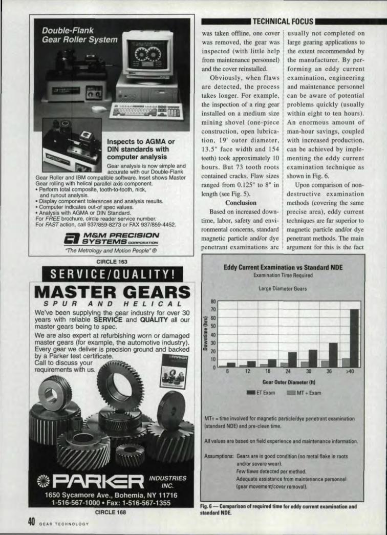
____ TECH'NICAL FOCUS ••••• _was taken affline,. one cover j usually nat completed allwas removed, [he gear was llarge gearing appli.cal:iolls toinspected (with little help ~ the extent recommended byfrom maintenance personnel) ~ the manufacturer. By per-and the cover reinstalled. I. forming an eddy current
Obviously, when flaws " examination, engineeringare detected, the process ~and maintenance per onneltakes longer. For example, i can be aware of potentialthe i.nspecti.oll of a ring gear : problems quickly (usuallyinstalled on a medium size j within eight to. ten hours).mining shovel (one-piece j An enormous amount ofconstruction. open lubrica- man-hour savings, coupledlion, 1.9' outer diameter, with increased production,13.5 H face width and l S4 can be achieved by imple-teeth) tockapproximately 1.0 menting the eddy currenthours. But 73 tooth roots examination technique as
shown in Fig. 6.Upon comparison of non-
contained cracks. Flaw sizeranged from 0.125" to 8" inlength (see Fig. 5). destructi ve examination
methods (covering the sameprecise area). eddy currenttechniques are far superior tomagnetic particle and/or dyepenetrant methods. The main
ConclusionBased on increased down-
time, labor. safety and envi-ronmentali concerns, standardmagnetic panicle and/or dyepenetrant examinations are argument for this .is the fact
Eddy Current bamination vs Standard NDEExamination Time Required
Large [)iameter Gears
M.-------------------~----~--~--__.70
f ~~--~----+----+----4-----~---+--:5 50III .
,5 4IJ 1----+----+_---+----4_----1-----+-i301---+--~--+-~---+-o 20~-----+----4_----r__==4--
101----+--=:+__-o '-_L.l:=-_ ........
12 24 30 36
Gaar Outer Diameter Ifd
_ET!Exam MT + Exam
MT+ "time involved for magnetic particle/dye penetrant examination(standard NOEl and pre-clean time.
Alil/alues are based on field experience and maintenance information.
Assumptions: Gears are in good condition (no melal flake in rootsa nd/or seve re wea rJ.Few flaws detected per method.Adequate assistance from maintenance personnel(gear movement/cover removal!.
IFig'.6i- Compari.son of requi~lId tim. f r ell'dy cwrrenllxami'ltatioll' IndItandl~d INDE.

_-----TECHNI:CAL.IFOCUS _that the potential for humanerror is greater using themagnetic particleand/or dyepenetrant techniques. Less,reliance nn componentcleaning. lighting conditionsand eyesight make eddy cur-rent testing the more depend-able examination method.Because of the localized scandesign of the 'eddy currentsystem and the wide cover-age areas (tooth faces) of meother method, accurateexamination method compar-isons could not be completedfor an entire gear.
For production and main-tenance planning taffs withadequate resources, the neweddy current and standardNDE methods work weBtogether. An ,effective use ofeddy currentand magneticparticle examination tech-nologies provides far excel-lent preventi ve mainte-nance. An eddy currentexaminanon on an annualbasis will pinpoint potential-ly hannful discontinuities atthe earliest point in time. A100% looth profile magneticparticle/dye penetrant exam-ination should be performedat five-year intervals tocheck for tooth wear andprofile flaws.
Because of demands forincreased production and thedowntime required to per-form standard NDE tech-niques, gear examinationsare frequently performedinadequately or not at all.For maintenance and engi-neering personnel worriedabout the downtime neededfor a gear inspection, theeddy current gear examina-tion system. quickly elimi-nates doubts whether apotentialily harmful conditionexists ill a pruticuJar gearingapplication, 0
Reter,ences:American Society of Testing
Materials. "Standard Practice forEddy Current Eaamination of SteelTubular Products Using MagneticSaturation." ASTM E 309·938.1994 Annual Book of ASTMStandards. Non-destructiveTesting. Volume 03.03, AmericanSociety of Testing Materials,Phiiadelphia,PA ..
American Society of TestingMaterials. "StandardPractice forMagnetic Particle Bxamlnation,"ASTM E 1444-94. 1994 AnnualBook of ASTM Standards, Non-destruaive Testing, Volume 03.03.American Society of TestingMaterials, Phi!!!delphla. PA.
American Society of TestingMaterials. "Standard Terminologyfor Nondestructive Examinations,"ASTM E }316·94. 1994 AnnualBook of ASTM Standards.Nondestructive Testing, Volume03!03. American Society of TestingMaterials, Philadelphia. PA.
Ceoo, V.S. et 11.1. Eddy CurrentTesting Volume 1 Test Method.The Atomic Energy of CanadaLimited ..
Davis, ,. Mark & K. M. King.Mathematical Formulas andReferences for NondestructiveTesting-Eddy Current. Firs!Edition, Art ROom Corporation,Itasca, It. 1994.
Eddy Currenl' Testing Chart,Hocking-Krllutbamer Branson.Inspec House, SL Albans, UK.
Mark's Standard Hand-bookfor Mechanical Engineers .. 9thEdition, McGraw-Hill, New York,1~18.
Marks, Danny N. GeneralEddy Curren! Study Guide, UltronIncorporated. MI.V,erno!], IL 1994.
Metals Handbook. De kEdition, American Society forMetals, Metals Park. Ohio, 1985.
Oberg, Erik er al, Machinery'sHandbook, 23rrd Edition, IndustrialPress Inc., New York, 1988.
Christopher E. IColUnsis a mechanical engineer withVI/ron Incorporated, a nonde-structive testing service and con-suiting company in Mr. Vernot),IL
T.. U. .... V.. nillk ...If you found this article ofinterest and/or useful.pleasecircle_
For /lIOI'I informetlon about.... llu"...... circleE.
Spira'l&: Srraight Reve'l Gear Manufacturi,ng'.Commercial tOIaircraft quality Igearing.
Spur,.hal,ical. splined shafts, linterna'l&:externa.l.shaved &:groundl,geoJs, Spirailibevel grinding.
Mil-I-45208· MH-STD~4S662.SPC
M~=,~~~!r ci,.?::'Ar.~s2.6069 Groesbeck Hwy. - (8101776·7580
Warren, MI480B9 fAX (8101716-2322
CIRCLE 113
·VlSIT OUR BOOTH" DECADE OF PERFORIU;NC'E
I I ~'~i' tt.!l. 1HJ-Dt.troR.II!Jc:l!,!ll:it
IJ I lit" n"r: !'JIUf'("""o;P! nr rrulll n-" uI I" Ilill Imrh.ch-pcml till Iht" (~LUtljl~ur lilt" pline, Fn"lu"uspline ..emtnnrs [J:rt~ dlif' pL.I'-rrt',·4 mL~\\ rr [n n ruIJlIlId~rslan<lilig"f Ihi, tlillkllh I'rnm~. \hu,(1"if'r 20 '~r..(lrll!lf spline ("x],rrir·IU'I'. Frf'm~n\1proff'~ ...inl1.n\ rrninor ""till rdu('.[lw dr ..lJ,:fll' r-,
pruUUl:('~ un'll in ..pt.·..-tor- .. in 1111'"..uL)I·ll~ .. rtanderds . Toleranemg . IIINIJl'dillnIethnds , Ul'si.~'fI • :\'hln'lIftu'l!ll'iDI'
I'll rf'rr-h'''' JWlff' mformarion, ur ..dlf'4)LI'lf'> 111(-'-worlds 1I1(1~1-l'mn~)h'lf~:;p)illf" Mt"Iuiullr. rallllli"
fru: lb.
14ses lI.b~u, FlG.dBrDDU~lld.WI 53005
Ph. 414'7.11'6777F... 414'7BH!aa2
CIRCLE1~7
MAV/JUNE 1997 41