ed&c times vol - dpstar.com.my · fuji ed & c times vol. 16 new products 3 low voltage air...
TRANSCRIPT
Vol. 16
62B9-E-0006a
New ProductsLow Voltage Air Circuit Breakers (ACB) DW Series ....................................................................................... 2Molded Case Circuit Breakers BX Series ...................................................................................................... 6Thermal overload relays TK13, TK26 .......................................................................................................... 10Contactors and Thermal Overload Relays FJ Series .................................................................................. 12Magnetic starter FJ Series, Starters with on-off pushbuttons ...................................................................... 14Mini contactor SK Series, Products with four-pole main contact, with printed circuit board installed ......... 16Industrial Relays SKH4AB, SKH4GB .......................................................................................................... 18DC Magnetic Contactor SB Series SB-N2 Type .......................................................................................... 20Time Delay Relays Super Timers ST7P-C Series ..................................................................................... 24Command Switches Integrated contact structure ........................................................................................ 26 AR15C•DR15C,AF15C•DF15C,AR16C•DR16C,AF16C•DF16CCam-type control selector switches AK7 Series .......................................................................................... 28High-Voltage Power Receiving and Distribution Protective Relay QHA Series ........................................... 30Analog unit for transducer F-MPC WS3 Series ........................................................................................... 32Power monitoring unit F-MPC Series Multi-circuit power monitoring unit F-MPC04P ................................ 34AC power regulator [APR] APR-D Series (three-phase) ............................................................................. 36Low-voltage control power transformers ...................................................................................................... 38
CU1F Series (for single-phase use) CU3F Series (for three-phase use)High-Voltage Alternating Current Load-Break Switch LBS Series............................................................... 40
Modified ProductsChanged Types ............................................................................................................................................ 42
Discontinued ProductsDiscontinued Products ................................................................................................................................. 44
FUJI ED & C TIMES Vol. 16
New ProductsNew Products
2
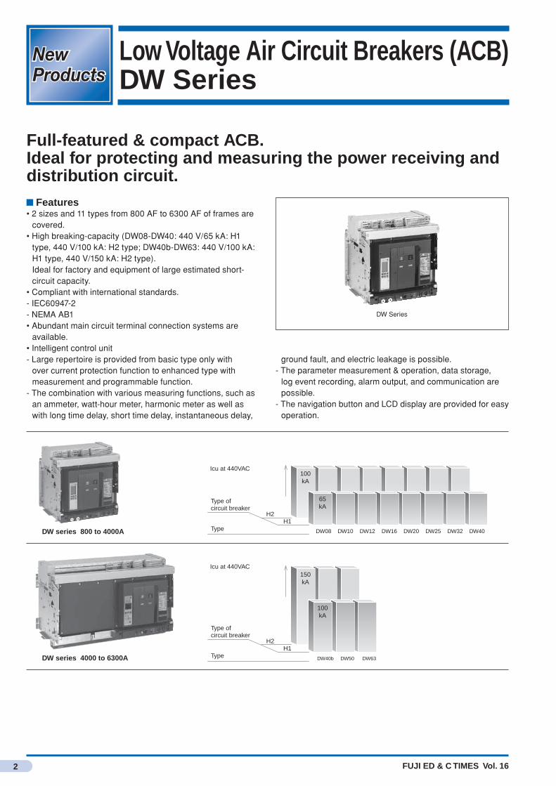
Low Voltage Air Circuit Breakers (ACB)DW Series
Full-featured & compact ACB.Ideal for protecting and measuring the power receiving and distribution circuit.
Features• 2 sizes and 11 types from 800 AF to 6300 AF of frames are
covered.• High breaking-capacity (DW08-DW40: 440 V/65 kA: H1
type, 440 V/100 kA: H2 type; DW40b-DW63: 440 V/100 kA: H1 type, 440 V/150 kA: H2 type).
Ideal for factory and equipment of large estimated short-circuit capacity.
• Compliant with international standards.- IEC60947-2- NEMA AB1• Abundant main circuit terminal connection systems are
available.• Intelligent control unit- Large repertoire is provided from basic type only with
over current protection function to enhanced type with measurement and programmable function.
- The combination with various measuring functions, such as an ammeter, watt-hour meter, harmonic meter as well as with long time delay, short time delay, instantaneous delay,
DW Series
100kA
150kA
100kA
65kA
DW08
DW40b DW50 DW63
DW10 DW12 DW16 DW20 DW25 DW32 DW40DW series 800 to 4000A
DW series 4000 to 6300A
H2
Type of circuit breaker
Icu at 440VAC
TypeH1
H2
Type of circuit breaker
Icu at 440VAC
TypeH1
ground fault, and electric leakage is possible.- The parameter measurement & operation, data storage,
log event recording, alarm output, and communication are possible.
- The navigation button and LCD display are provided for easy operation.

FUJI ED & C TIMES Vol. 16
New Products
3
Low Voltage Air Circuit Breakers (ACB) DW Series
Specifications
Type DW08 DW10 DW12Appearance
Number of poles 3, 4Rated insulation Voltage Ui (V) 1000Impulse withstand voltage Uimp (kV) 12Rated operational voltage Ue (VAC 50/60Hz) 690Suitability for isolation IEC60947-2, JISC8201-2-1 ○Pollution degree IEC60664-1, JISC60664-1 4Type of circuit breaker H1 H2 H1 H2 H1 H2Rated current(A) Inat 40℃
Vertical rear connection
IEC60947-2, JISC8201-2-1 Ann1 800 1000 1250JISC8201-2-1 Ann2 800 1000 1250
Horizontal rear connectionFront connection
IEC60947-2, JISC8201-2-1 Ann1 800 1000 1250JISC8201-2-1 Ann2 800 1000 1250
Sensor rating (A) 400, 630, 800 400, 630, 800, 1000
630, 800, 1000, 1250
IEC60947-2JISC8201-2-1Ann1, Ann2
Ultimate breaking capacity IcuRated service breaking capacity Ics(kA rms) Icu = Ics
220/415VAC 65 100 65 100 65 100440VAC 65 100 65 100 65 100690VAC 65 85 65 85 65 85
Rated making capacity Icm(kA peak)
220/415VAC 143 220 143 220 143 220440VAC 143 220 143 220 143 220690VAC 143 187 143 187 143 187
NEMA AB1 Breaking capacity(kA)
240/480VAC 65 100 65 100 65 100600VAC 65 85 65 85 65 85
Utilisation category BRated short-time withstand current Icw (kA rms)
1s 65 85 65 85 65 853s 36 50 36 50 36 50
Break time (ms) between tripping order and arc extinction 25Closing time (ms) <70Service life(C/O Cycles x1000)
Mechanical With maintenance 25Without maintenance 12.5
Electrical Without maintenance 460VAC In 10690VAC In 10
Motor power (AC3, IEC60947-4-1) 690VAC 6Connection Drawout Front Connection ○
Rear Connection ○Fixed Front Connection ○
Rear Connection ○Control units 2.0, 5.0, 2.0A, 5.0A, 6.0A, 7.0A, 2.0E, 5.0E, 6.0E, 5.0P,
6.0P, 7.0P, 5.0H, 6.0H, 7.0HDimensions (mm)H x W x D
Drawout, Rear Connection 3P 439 × 441 × 3954P 439 × 556 × 395
Fixed, Rear Connection 3P 352 × 422 × 2974P 352 × 537 × 297
Mass (kg) Drawout 3P/4P 90/120Fixed 3P/4P 60/80
New Products
4 FUJI ED & C TIMES Vol. 16
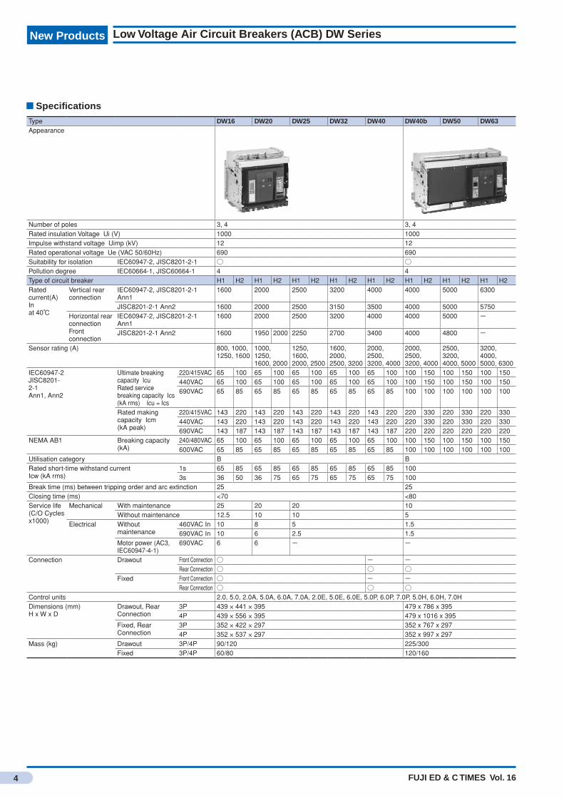
Low Voltage Air Circuit Breakers (ACB) DW Series
Specifications
Type DW16 DW20 DW25 DW32 DW40 DW40b DW50 DW63Appearance
Number of poles 3, 4 3, 4Rated insulation Voltage Ui (V) 1000 1000Impulse withstand voltage Uimp (kV) 12 12Rated operational voltage Ue (VAC 50/60Hz) 690 690Suitability for isolation IEC60947-2, JISC8201-2-1 ○ ○Pollution degree IEC60664-1, JISC60664-1 4 4Type of circuit breaker H1 H2 H1 H2 H1 H2 H1 H2 H1 H2 H1 H2 H1 H2 H1 H2Rated current(A) Inat 40℃
Vertical rear connection
IEC60947-2, JISC8201-2-1 Ann1
1600 2000 2500 3200 4000 4000 5000 6300
JISC8201-2-1 Ann2 1600 2000 2500 3150 3500 4000 5000 5750Horizontal rear connectionFront connection
IEC60947-2, JISC8201-2-1 Ann1
1600 2000 2500 3200 4000 4000 5000 -
JISC8201-2-1 Ann2 1600 1950 2000 2250 2700 3400 4000 4800 -
Sensor rating (A) 800, 1000, 1250, 1600
1000, 1250, 1600, 2000
1250, 1600, 2000, 2500
1600, 2000, 2500, 3200
2000, 2500, 3200, 4000
2000, 2500, 3200, 4000
2500, 3200, 4000, 5000
3200, 4000, 5000, 6300
IEC60947-2JISC8201-2-1Ann1, Ann2
Ultimate breaking capacity IcuRated service breaking capacity Ics(kA rms) Icu = Ics
220/415VAC 65 100 65 100 65 100 65 100 65 100 100 150 100 150 100 150440VAC 65 100 65 100 65 100 65 100 65 100 100 150 100 150 100 150690VAC 65 85 65 85 65 85 65 85 65 85 100 100 100 100 100 100
Rated making capacity Icm(kA peak)
220/415VAC 143 220 143 220 143 220 143 220 143 220 220 330 220 330 220 330440VAC 143 220 143 220 143 220 143 220 143 220 220 330 220 330 220 330690VAC 143 187 143 187 143 187 143 187 143 187 220 220 220 220 220 220
NEMA AB1 Breaking capacity(kA)
240/480VAC 65 100 65 100 65 100 65 100 65 100 100 150 100 150 100 150600VAC 65 85 65 85 65 85 65 85 65 85 100 100 100 100 100 100
Utilisation category B BRated short-time withstand current Icw (kA rms)
1s 65 85 65 85 65 85 65 85 65 85 1003s 36 50 36 75 65 75 65 75 65 75 100
Break time (ms) between tripping order and arc extinction 25 25Closing time (ms) <70 <80Service life(C/O Cycles x1000)
Mechanical With maintenance 25 20 20 10Without maintenance 12.5 10 10 5
Electrical Without maintenance
460VAC In 10 8 5 1.5690VAC In 10 6 2.5 1.5
Motor power (AC3, IEC60947-4-1)
690VAC 6 6 - -
Connection Drawout Front Connection ○ - -Rear Connection ○ ○ ○
Fixed Front Connection ○ - -Rear Connection ○ ○ ○
Control units 2.0, 5.0, 2.0A, 5.0A, 6.0A, 7.0A, 2.0E, 5.0E, 6.0E, 5.0P, 6.0P, 7.0P, 5.0H, 6.0H, 7.0HDimensions (mm)H x W x D
Drawout, Rear Connection
3P 439 × 441 × 395 479 x 786 x 3954P 439 × 556 × 395 479 x 1016 x 395
Fixed, Rear Connection
3P 352 × 422 × 297 352 x 767 x 2974P 352 × 537 × 297 352 x 997 x 297
Mass (kg) Drawout 3P/4P 90/120 225/300Fixed 3P/4P 60/80 120/160

5FUJI ED & C TIMES Vol. 16
New Products
Intelligent control unit
Name Unit 2:for basic protection
Unit 5:for selective protection
Unit 6:for selective + ground fault protection
Unit 7:for selective+ earth leakage protection
Current protection
0 Ir Isd I
t
0 Ir I
t
IiIsd 0 Ir I
t
IiIsd
0 IIg
t
0 Ir I
t
IiIsd
0 I
t
I∆n
Protection Long time+ instantaneous
Long time+ short time+ instantaneous
Long time+ short time+ instantaneous+ ground fault
Long time+ short time+ instantaneous+ earth leakage
Protection only
2.0 Micrologic 2.0
.4.5.6
.7.8
.9.95.98
1
x Ir
22.5
3 4 56
8101.5
setting
Isd
.512
48
121620
instantaneous
long timealarmIr tr
(s)
x In at 6 Ir24
5.0 Micrologic 5.0
setting delay
short timeI itsd
(s)
long timealarm
x In
34
68
101215
off2
.4.5.6
.7.8
.9.95.98
1
Ir
x In
x Ir
22.5
3 4 568
10
Isd
1.5
.512
48
121620
tr(s)
at 6 I24
on I2t
.2
.3.4 .4
.1
.2.3
.10
instantaneous
- -
Measurement and programmable protection
A: with ammeter• Phase current (I1, I2, I3), neutral current (IN), ground-fault current (earth-fault), earth-leakage current (earth leakage), and maximum earth-leakage current
• Failure cause indicator• Preset constant (A) and time period (s) indicator
2.0A
40
100%
%
menu
5.0A
40
100%
%
menu
6.0A
40
100%
%
menu
7.0A
40
100%
%
menu
E: A + energy meter• In addition to measurement of type A, measurement of voltage, power factor, electric power, and electric energy (watt-hour)• Calculation of demand current• "Quick view" function automatically indicating most effective value (default or optional)
2.0EMicrologic 2.0 E
40
100%
%
menu
long timealarm
instantaneous
5.0EMicrologic 5.0 E
40
100%
%
short time
long timealarm
menu
6.0EMicrologic 6.0 E
40
100%
%
short time
long timealarm
ground fault
menu
-
P: E + programmable protection• Voltage, current, electric power, electric energy (watt-hour), frequency, peak voltage, peak current, and minimum and maximum peak current
• IDMTL long time protection, minimum & maximum voltage and frequency, unbalanced voltage & current, phase sequence, and reverse power
• Disconnection and reconnection of load because of power or current
• Measurement of breaking current, failure cause indicator, maintenance information, event history, timestamp, etc.
- 5.0P 6.0P 7.0P
H: P + harmonic meter• Power quality: up to 31th harmonic fundamental waves, distortion factor
• Waveform recording because of failure, alarm, or necessity
• Advanced alarm program: Setup and operation
- 5.0H 6.0H 7.0H
Low Voltage Air Circuit Breakers (ACB) DW Series
FUJI ED & C TIMES Vol. 16
New ProductsNew Products
6
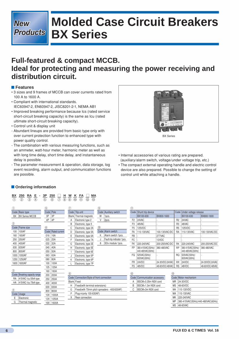
Molded Case Circuit BreakersBX Series
Full-featured & compact MCCB.Ideal for protecting and measuring the power receiving and distribution circuit.
Features• 3 sizes and 9 frames of MCCB can cover currents rated from
100 A to 1600 A.• Compliant with international standards. IEC60947-2, EN60947-2, JISC8201-2-1, NEMA AB1• Improved breaking performance because Ics (rated service
short-circuit breaking capacity) is the same as Icu (rated ultimate short-circuit breaking capacity).
• Control unit & display unit- Abundant lineups are provided from basic type only with
over current protection function to enhanced type with power quality control.
- The combination with various measuring functions, such as an ammeter, watt-hour meter, harmonic meter as well as with long time delay, short time delay, and instantaneous delay is possible.
- The parameter measurement & operation, data storage, log event recording, alarm output, and communication functions are possible.
BX Series
• Internal accessories of various rating are prepared. (auxiliary/alarm switch, voltage/under voltage trip, etc.)• The compact external operating handle and electric control
device are also prepared. Possible to change the setting of control unit while attaching a handle.
Ordering information
BX 250 RA E - 3P 250 □ H W K FA □ MA① ⑤ ⑫③ ④ ⑦ ⑧ ⑨ ⑩ ⑪ ⑬② ⑥
①Code Basic typeBX BX Series MCCB
②Code Frame size100 100AF160 160AF250 250AF400 400AF630 630AF800 800AF
1000 1000AF1250 1250AF1600 1600AF
③Code Breaking capacity rangeRA 415VAC/ Icu 50kA typeHA 415VAC/ Icu 70kA type
④Code Usage
E ElectronicG Thermal-magnetic
⑥Code Rated current016 16A025 25A032 32A040 40A050 50A063 63A080 80A100 100A125 125A160 160A200 200A250 250A400 400A630 630A800 800A10X 1000A12X 1250A16X 1600A
⑦Code Trip unitBlank Thermal-magnetic
A Electronic type 2B Electronic, type 5C Electronic, type 2AD Electronic, type 5AE Electronic, type 6AF Electronic, type 7AG Electronic, type 2EH Electronic, type 5EI Electronic, type 6EJ Electronic, type 5PK Electronic, type 6PL Electronic, type 7P
⑧Code Connection/Style of front connectionBlank Fixed
H Fixed(with terminal extensions)G Fixed(with 70mm pitch spreaders - 400/630AF)P Plug-in(only 100-630AF)X Rear connection
⑩Code Alarm switch
K Alarm switch 1pcs.J Fault-trip indicator 1pcs.8 SDx module 1pcs.
⑫Code Communication accessory
A BSCM+0.35m NSX cordB BSCM+1.3m NSX cordC BSCM+3m NSX cord
⑬Code Motor mechanismMR 24-30VDCMS 48-60VDCM4 110-130VDCMA 110-130VACMK 220-240VACMP 380-415VAC(50Hz)/440-480VAC(60Hz)M3 48-60VAC
⑪Code Shunt trip device Code Under voltage release
BX100-630 BX800-1600 BX100-630 BX800-1600F2 24VAC - R2 24VAC -F3 48VAC - R3 48VAC -F5 125VDC - R5 125VDC -FA 110-130VAC 100-130VAC/DC RA 110-130VAC 100-130VAC/DCFB - 277VAC - -FC - 12VDC - -FK 220-240VAC 200-250VAC/DC RK 220-240VAC 200-250VAC/DCFP 380-415VAC(50Hz)/
440-480VAC(60Hz)380-480VAC RP 380-415VAC(50Hz)/
440-480VAC(60Hz)380-480VAC
FQ 525VAC(50Hz)/ 600VAC(60Hz)
- RQ 525VAC(50Hz)/600VAC(60Hz)
-
FR 24VDC 24-30VDC/24VAC RR 24VDC 24-30VDC/24VACFS 48VDC 48-60VDC/48VAC RS 48VDC 48-60VDC/48VAC
⑨Code Auxiliary switch
W 1pcs.V 2pcs.
⑤Code Pole
3P 3P4P 4P
FUJI ED & C TIMES Vol. 16
New Products
7
Molded Case Circuit Breakers BX Series
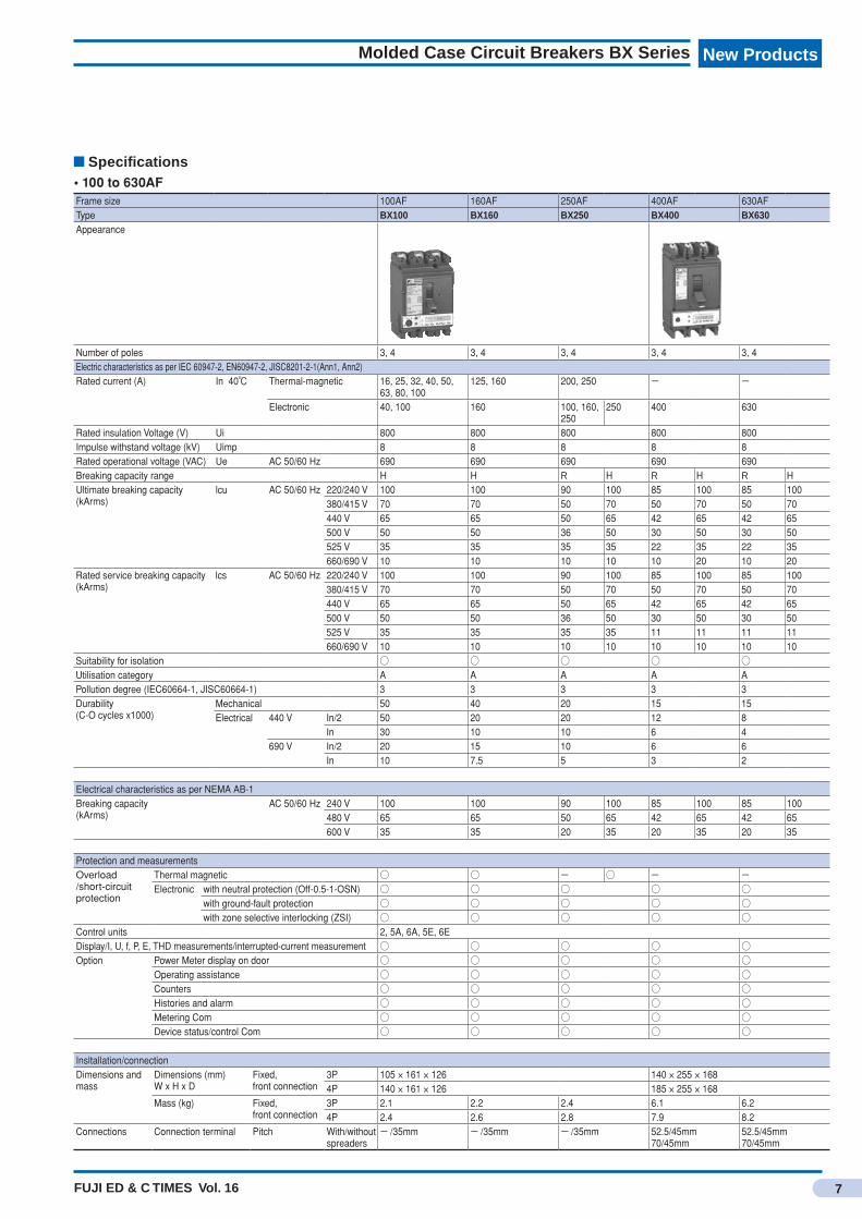
Specifications• 100 to 630AFFrame size 100AF 160AF 250AF 400AF 630AFType BX100 BX160 BX250 BX400 BX630Appearance
Number of poles 3, 4 3, 4 3, 4 3, 4 3, 4Electric characteristics as per IEC 60947-2, EN60947-2, JISC8201-2-1(Ann1, Ann2)Rated current (A) In 40℃ Thermal-magnetic 16, 25, 32, 40, 50,
63, 80, 100125, 160 200, 250 - -
Electronic 40, 100 160 100, 160, 250
250 400 630
Rated insulation Voltage (V) Ui 800 800 800 800 800Impulse withstand voltage (kV) Uimp 8 8 8 8 8Rated operational voltage (VAC) Ue AC 50/60 Hz 690 690 690 690 690Breaking capacity range H H R H R H R HUltimate breaking capacity(kArms)
lcu AC 50/60 Hz 220/240 V 100 100 90 100 85 100 85 100380/415 V 70 70 50 70 50 70 50 70440 V 65 65 50 65 42 65 42 65500 V 50 50 36 50 30 50 30 50525 V 35 35 35 35 22 35 22 35660/690 V 10 10 10 10 10 20 10 20
Rated service breaking capacity(kArms)
lcs AC 50/60 Hz 220/240 V 100 100 90 100 85 100 85 100380/415 V 70 70 50 70 50 70 50 70440 V 65 65 50 65 42 65 42 65500 V 50 50 36 50 30 50 30 50525 V 35 35 35 35 11 11 11 11660/690 V 10 10 10 10 10 10 10 10
Suitability for isolation ○ ○ ○ ○ ○Utilisation category A A A A APollution degree (IEC60664-1, JISC60664-1) 3 3 3 3 3Durability(C-O cycles x1000)
Mechanical 50 40 20 15 15Electrical 440 V In/2 50 20 20 12 8
In 30 10 10 6 4690 V In/2 20 15 10 6 6
In 10 7.5 5 3 2
Electrical characteristics as per NEMA AB-1Breaking capacity (kArms)
AC 50/60 Hz 240 V 100 100 90 100 85 100 85 100480 V 65 65 50 65 42 65 42 65600 V 35 35 20 35 20 35 20 35
Protection and measurementsOverload /short-circuit protection
Thermal magnetic ○ ○ - ○ - -Electronic with neutral protection (Off-0.5-1-OSN) ○ ○ ○ ○ ○
with ground-fault protection ○ ○ ○ ○ ○with zone selective interlocking (ZSI) ○ ○ ○ ○ ○
Control units 2, 5A, 6A, 5E, 6EDisplay/I, U, f, P, E, THD measurements/interrupted-current measurement ○ ○ ○ ○ ○Option Power Meter display on door ○ ○ ○ ○ ○
Operating assistance ○ ○ ○ ○ ○Counters ○ ○ ○ ○ ○Histories and alarm ○ ○ ○ ○ ○Metering Com ○ ○ ○ ○ ○Device status/control Com ○ ○ ○ ○ ○
Insltallation/connectionDimensions and mass
Dimensions (mm) W x H x D
Fixed, front connection
3P 105 × 161 × 126 140 × 255 × 1684P 140 × 161 × 126 185 × 255 × 168
Mass (kg) Fixed, front connection
3P 2.1 2.2 2.4 6.1 6.24P 2.4 2.6 2.8 7.9 8.2
Connections Connection terminal Pitch With/without spreaders
- /35mm - /35mm - /35mm 52.5/45mm70/45mm
52.5/45mm70/45mm
New Products
8 FUJI ED & C TIMES Vol. 16
Molded Case Circuit Breakers BX Series
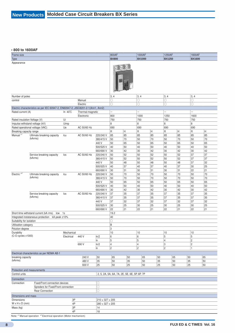
• 800 to 1600AFFrame size 800AF 1000AF 1250AF 1600AFType BX800 BX1000 BX1250 BX1600Appearance
Number of poles 3, 4 3, 4 3, 4 3, 4control Manual ○ ○ ○ ○
Electric ○ ○ ○ ○Electric characteristics as per IEC 60947-2, EN60947-2, JISC8201-2-1(Ann1, Ann2)Rated current (A) In 40℃ Thermal-magnetic - - - -
Electronic 800 1000 1250 1600Rated insulation Voltage (V) Ui 750 750 750 750Impulse withstand voltage (kV) Uimp 8 8 8 8Rated operational voltage (VAC) Ue AC 50/60 Hz 690 690 690 690Breaking capacity range R H R H R H R HManual *1 Ultimate breaking capacity
(kArms)lcu AC 50/60 Hz 220/240 V 85 85 85 85 85 85 85 85
380/415 V 50 70 50 70 50 70 50 70440 V 50 65 50 65 50 65 50 65500/525 V 40 50 40 50 40 50 40 50660/690 V 30 42 30 42 30 42 30 42
Service breaking capacity (kArms)
Ics AC 50/60 Hz 220/240 V 50 52 50 52 50 52 37 37380/415 V 50 52 50 52 50 52 37 37440 V 50 48 50 48 50 48 37 32500/525 V 40 37 40 37 40 37 30 25660/690 V 30 31 30 31 30 31 22 21
Electric *2 Ultimate breaking capacity (kArms)
lcu AC 50/60 Hz 220/240 V 50 70 50 70 50 70 50 70380/415 V 50 70 50 70 50 70 50 70440 V 50 65 50 65 50 65 50 65500/525 V 40 50 40 50 40 50 40 50660/690 V 30 42 30 42 30 42 30 42
Service breaking capacity (kArms)
Ics AC 50/60 Hz 220/240 V 37 35 37 35 37 35 37 35380/415 V 37 35 37 35 37 35 37 35440 V 37 32 37 32 37 32 37 32500/525 V 30 25 30 25 30 25 30 25660/690 V 22 21 22 21 22 21 22 21
Short-time withstand current (kA rms) Icw 1s 19.2Integrated instataneous protection kA peak ±10% 40Suitability for isolation ○Utilisation category BPolution degree 3Durability(C-O cycles x1000)
Mechanical 10 10 10 10Electrical 440 V In/2 6 6 5 5
In 5 5 4 2690 V In/2 4 4 3 2
In 2 2 2 1
Electrical characteristics as per NEMA AB-1breaking capacity (kArms)
240 V 50 65 50 65 50 65 50 65480 V 35 50 35 50 35 50 35 50600 V 25 50 25 50 25 50 25 50
Protection and measurementsControl units 2, 5, 2A, 5A, 6A, 7A, 2E, 5E, 6E, 5P, 6P, 7P
ConnectionConnection Fixed/Front connection devices ○
Spreders for Fixed/Front connection ○Rear Connection ○
Dimensions and massDimensionsW x H x D (mm)
3P 210 × 327 × 2054P 280 × 327 × 205
Mass (kg) 3P 144P 18
Note: *1 Manual operation *2 Electrical operation (Motor mechanism)
9FUJI ED & C TIMES Vol. 16
New ProductsMolded Case Circuit Breakers BX Series
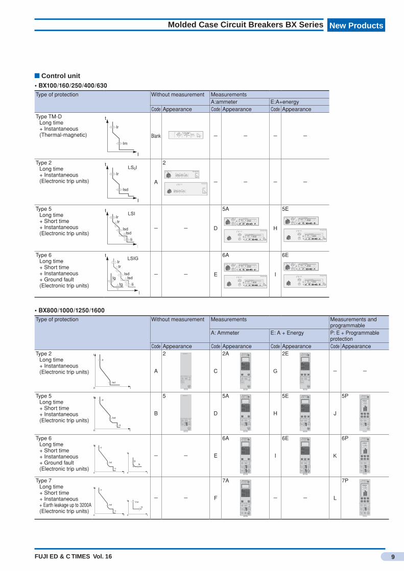
Control unit• BX100/160/250/400/630Type of protection Without measurement Measurements
A:ammeter E:A+energyCode Appearance Code Appearance Code Appearance
Type TM-DLong time + Instantaneous (Thermal-magnetic) Blank - - - -
Type 2Long time + Instantaneous (Electronic trip units) A
2
- - - -
Type 5Long time + Short time + Instantaneous (Electronic trip units)
- - D
5A
H
5E
Type 6Long time + Short time + Instantaneous + Ground fault (Electronic trip units)
- - E
6A
I
6E
• BX800/1000/1250/1600Type of protection Without measurement Measurements Measurements and
programmableA: Ammeter E: A + Energy P: E + Programmable
protectionCode Appearance Code Appearance Code Appearance Code Appearance
Type 2Long time + Instantaneous (Electronic trip units) A
2 Micrologic 2.0
.4.5.6
.7 .8 .9.95.98
1
x Ir
22.5
3 4 568
5.1 01
setting
Isd
.512
48
121620
instantaneous
long timealarmIr tr
(s)
x In at 6 Ir24
C
2A Micrologic 2.0 A
40
100%
%
menu
long timealarm
instantaneous
.4.5.6
.7 .8 .9.95.98
1
Ir
x In .512
48
121620
tr(s)
at 6 Ir24
x Ir
22.5
3 45
6
1.5
setting
Isd
810
G
2E Micrologic 2.0 E
40
100%
%
menu
long timealarm
instantaneous
.4.5.6
.7 .8 .9.95.98
1
Ir
x In .512
48
121620
tr(s)
at 6 Ir24
x Ir
22.5
3 45
6
1.5
setting
Isd
810
- -
Type 5Long time + Short time + Instantaneous (Electronic trip units)
B
5 Micrologic 5.0
setting delay
short timeI itsd
(s)
long timealarm
x In
34
68 10
1215
2 ffo
.4.5.6
.7 .8 .9.95.98
1
Ir
x In
x Ir
22.5
3 4 568
10
Isd
1.5
.512
48
121620
tr(s)
at 6 Ir24
on I2t
.2
.3.4 .4
.1
.2.3
.10
instantaneous
D
5A Micrologic 5.0 A
40
100%
%
menu
delay
short timetsd(s)
long timealarmtr
(s)
setting
.4.5.6
.7 .8 .9.95.98
1
Ir
x In .512
4 8 121620
at 6 Ir24
x Ir
22.5
3 4 568
10
Isd
1.5on I
2t
.2
.4 .4
.1
.3
.10
I i
x In
34
8
off2
.3
instantaneous
.26
15
1012
H
5E Micrologic 5.0 E
40
100%
%
delay
short timetsd(s)
long timealarmtr
(s)
setting
.4.5.6
.7 .8 .9.95.98
1
Ir
x In .512
4 8 121620
at 6 Ir24
x Ir
22.5
3 4 568
10
Isd
1.5on I
2t
.2
.4 .4
.1
.3
.10
I i
x In
34
8
off2
.3
instantaneous
.26
15
1012
menu
J
5P Micrologic 5.0 P
delaysettingx Ir
22.5
3 4 568
10
Isd
1.5
.4.5.6
.7 .8 .9.95.98
1
short timeI itsd
(s)
on I2t
.2
.3.4 .4
.1
.2.3
.10off
instantaneous
long timealarmIr
x In .512
48
121620
tr(s)
@ 6 Ir24
x In
test
2
410
3
6 81215
off
4260AN 1 2 3
100
50
0
Type 6Long time + Short time + Instantaneous + Ground fault (Electronic trip units)
- - E
6A Micrologic 6.0 A
40
100%
%
menu
delay
short time
on I2t
.2
.3.4 .4
.1
.2
.10
long timealarm
ground fault
setting
4
test
.4.5.6
.7 .8 .9.95.98
1
Ir
x In .512
48
121620
tr(s)
at 6 Ir24
x Ir
22.5
3 4 568
10
Isd
1.5
tsd(s)
x In
3
6 8 101215
off2
BC
D E FGH
I
Ig
Aon I
2t
.2
.3.4 .4
.1
.2.3
.10off
tg(s)
.1
.3instantaneous
I i
I
6E Micrologic 6.0 E
40
100%
%
delay
short time
on I2t
.2
.3.4 .4
.1
.2
.10
long timealarm
ground fault
setting
4
test
.4.5.6
.7 .8 .9.95.98
1
Ir
x In .512
48
121620
tr(s)
at 6 Ir24
x Ir
22.5
3 4 568
10
Isd
1.5
tsd(s)
x In
3
6 8 101215
off2
BC
D E FGH
I
Ig
Aon I
2t
.2
.3.4 .4
.1
.2.3
.10off
tg(s)
.1
.3instantaneous
I i
menu
K
6P Micrologic 6.0 P
.4.5.6
.7 .8 .9.95.98
1
delay
short timeI itsd
(s)
on I2t
.2
.3.4 .4
.1
.2.3
.10off
instantaneous
long timealarmIr
x In
ground fault
BC
D E FGH
J
Ig tg(s)
on I2t
.2
.3.4 .4
.1
.2.3
.10off
A
settingx Ir
22.5
3 4 568
10
Isd
1.5
.512
48
121620
tr(s)
@ 6 Ir24
x In
test
2
410
3
6 81215
off
4260AN 1 2 3
100
50
0
Type 7Long time + Short time + Instantaneous + Earth leakage up to 3200A (Electronic trip units)
- - F
7A Micrologic 7.0 A
40
100%
%
menu
.98
delay
short time
off
long timealarm
setting
earth leakage
test
.4.5.6
.7 .8 .9.95
1
Ir
x In
tr(s)
.512
48
121620
at 6 Ir24
x Ir
22.5
3 4 568
10
Isd
1.5
tsd(s)
on I2t
.2
.3.4 .4
.1
.2.3
.10
x In
34
6 8 101215
off2
12
3 5 71020
30.5
I∆n
800
∆I
60
140
230 350
instantaneousI i
- - L
7P Micrologic 7.0 P
.4.5.6
.7 .8 .9.95.98
1
delay
short timeI itsd
(s)
on I2t
.2
.3.4 .4
.1
.2.3
.10off
instantaneous
long timealarmIr
x In
settingx Ir
22.5
3 4 568
10
Isd
1.5
.512
48
121620
tr(s)
@ 6 Ir24
800
earth leakage
12
3 5 71020
30
t(ms)
60.5
140
230 350
I n(A)
x In
test
2
410
3
6 81215
off
4260AN 1 2 3
100
50
0

FUJI ED & C TIMES Vol. 16
New ProductsNew Products
10
Thermal overload relaysTK13, TK26
Full model change for low-rating Thermal Overload Relays (0.1 to 26 A)
Features• Phase-loss protection on standard models.• Terminal arrangement changed to greatly improve ease of
wiring.• Standard-feature dial cover that opens and closes to prevent
unintentional operation.• Conforming to, or certified major certifications such as IEC, UL, and CCC.• All materials used are compliant to RoHS Directive and the main components are easy to recycle.
TK13- TN TK26- TN
NEW
SpecificationsType Ampere setting range
(Specification codes for ampere setting range are given in brackets [ ].)Contactors to be combinedNo terminal cover With terminal cover
TK13- TN TK13- 0.1-0.15 [P10] 0.95-1.45 [P95] 7-10.5 [007] SC-030.13-0.2 [P13] 1.4-2.1 [1P4] 9-13 [009] SC-00.18-0.27 [P18] 1.7-2.6 [1P7] SC-050.24-0.36 [P24] 2.2-3.4 [2P2]0.34-0.52 [P34] 2.8-4.2 [2P8]0.48-0.72 [P48] 4-6 [004]0.64-0.96 [P64] 5-7.5 [005]0.8-1.2 [P80] 6-9 [006]
TK26- TN TK26- 0.1-0.15 [P10] 0.95-1.45 [P95] 7-10.5 [007] SC-4-00.13-0.2 [P13] 1.4-2.1 [1P4] 9-13 [009] SC-4-10.18-0.27 [P18] 1.7-2.6 [1P7] 12-18 [012] SC-5-10.24-0.36 [P24] 2.2-3.4 [2P2] 16-22 [016]0.34-0.52 [P34] 2.8-4.2 [2P8]0.48-0.72 [P48] 4-6 [004]0.64-0.96 [P64] 5-7.5 [005]0.8-1.2 [P80] 6-9 [006]
Note 1. Replace in the type number with the specification code for the ampere setting range.
Type number nomenclature
TK13 − 2P8 TN
(1) Type
(2) Ampere setting range (3) Terminal cover With terminal cover: Blank No terminal cover: TN
International standardsModels Conforming standards Certified standards EC Directives Certification
organization
IEC EN JIS UL CSA GB CE TÜV
International Europe Japan USA Canada China Europe Germany
EN JISTK13TK26 m m m m m m m m
Note m : Compliance with standard models.
FUJI ED & C TIMES Vol. 16
New Products
11
Thermal overload relay TK13, TK26
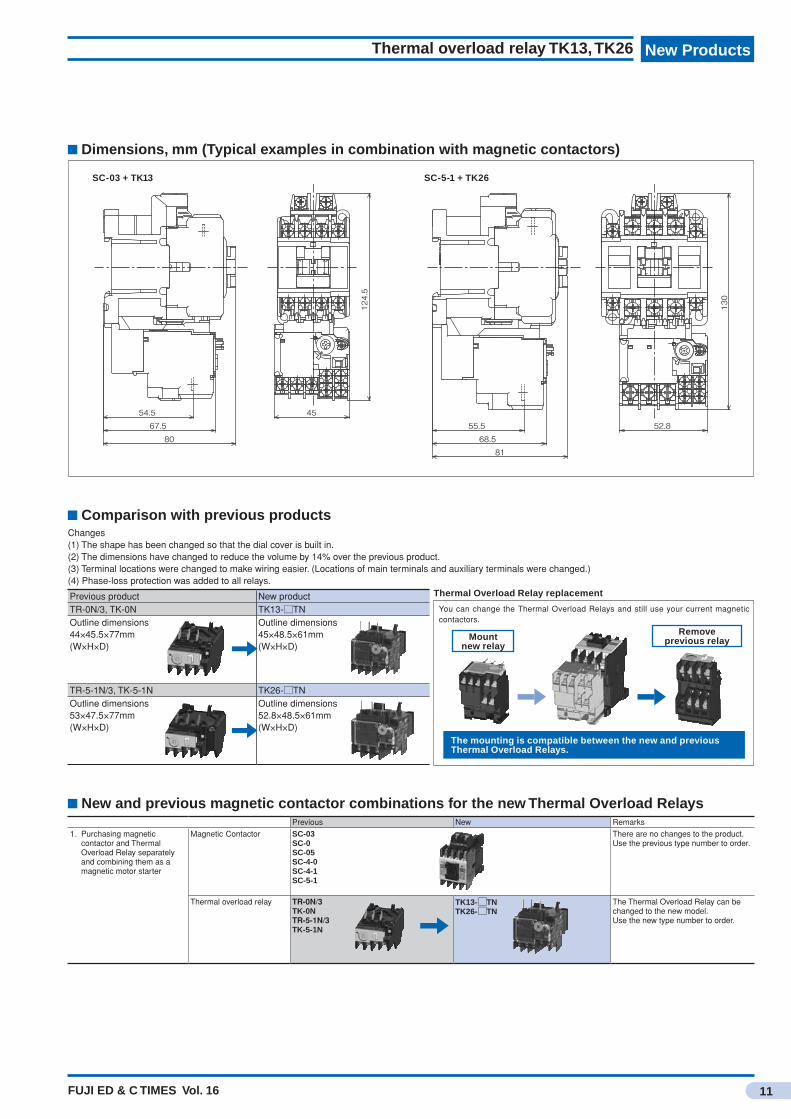
Changes(1) The shape has been changed so that the dial cover is built in.(2) The dimensions have changed to reduce the volume by 14% over the previous product.(3) Terminal locations were changed to make wiring easier. (Locations of main terminals and auxiliary terminals were changed.)(4) Phase-loss protection was added to all relays.
Previous product New productTR-0N/3, TK-0N TK13- TNOutline dimensions44×45.5×77mm(W×H×D)
Outline dimensions45×48.5×61mm(W×H×D)
TR-5-1N/3, TK-5-1N TK26- TNOutline dimensions53×47.5×77mm(W×H×D)
Outline dimensions52.8×48.5×61mm(W×H×D)
Comparison with previous products
You can change the Thermal Overload Relays and still use your current magnetic contactors.
The mounting is compatible between the new and previous Thermal Overload Relays.
Thermal Overload Relay replacement
Mount new relay
Remove previous relay
Dimensions, mm (Typical examples in combination with magnetic contactors)
SC-03 + TK13 SC-5-1 + TK26
SC-5-1+TK26SC-03/E02A+TK13
130
52.8
8168.5
55.5
124.5
45
80
67.554.5
New and previous magnetic contactor combinations for the new Thermal Overload RelaysPrevious New Remarks
1.Purchasing magnetic contactor and Thermal Overload Relay separately and combining them as a magnetic motor starter
MagneticContactor SC-03SC-0SC-05SC-4-0SC-4-1SC-5-1
There are no changes to the product.Use the previous type number to order.
Thermal overload relay TR-0N/3TK-0NTR-5-1N/3TK-5-1N
TK13- TNTK26- TN
The Thermal Overload Relay can be changed to the new model.Use the new type number to order.
FUJI ED & C TIMES Vol. 16
New ProductsNew Products
12
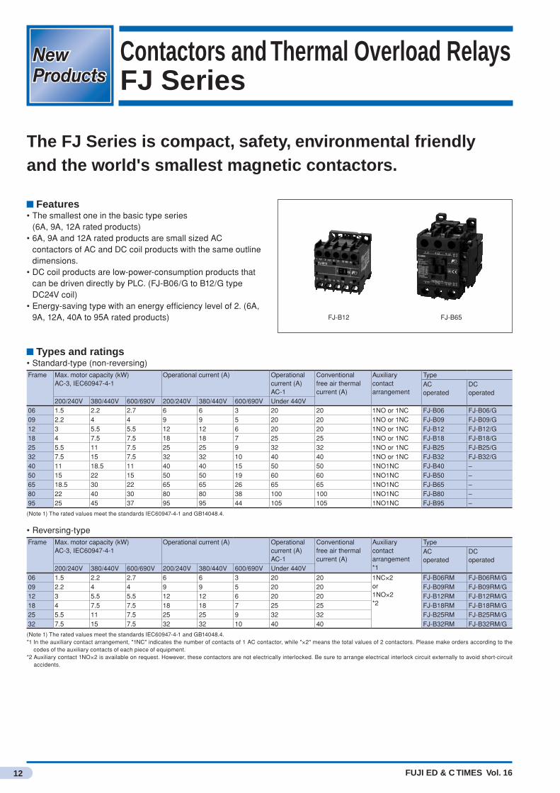
Contactors and Thermal Overload RelaysFJ Series
The FJ Series is compact, safety, environmental friendly and the world's smallest magnetic contactors.
Features• The smallest one in the basic type series (6A, 9A, 12A rated products)• 6A, 9A and 12A rated products are small sized AC
contactors of AC and DC coil products with the same outline dimensions.
• DC coil products are low-power-consumption products that can be driven directly by PLC. (FJ-B06/G to B12/G type DC24V coil)
• Energy-saving type with an energy efficiency level of 2. (6A, 9A, 12A, 40A to 95A rated products) FJ-B12 FJ-B65
Types and ratings• Standard-type (non-reversing)Frame Max. motor capacity (kW)
AC-3, IEC60947-4-1Operational current (A) Operational
current (A)AC-1
Conventional free air thermalcurrent (A)
Auxiliarycontactarrangement
TypeAC operated
DC operated
200/240V 380/440V 600/690V 200/240V 380/440V 600/690V Under 440V06 1.5 2.2 2.7 6 6 3 20 20 1NO or 1NC FJ-B06 FJ-B06/G09 2.2 4 4 9 9 5 20 20 1NO or 1NC FJ-B09 FJ-B09/G12 3 5.5 5.5 12 12 6 20 20 1NO or 1NC FJ-B12 FJ-B12/G18 4 7.5 7.5 18 18 7 25 25 1NO or 1NC FJ-B18 FJ-B18/G25 5.5 11 7.5 25 25 9 32 32 1NO or 1NC FJ-B25 FJ-B25/G32 7.5 15 7.5 32 32 10 40 40 1NO or 1NC FJ-B32 FJ-B32/G40 11 18.5 11 40 40 15 50 50 1NO1NC FJ-B40 –50 15 22 15 50 50 19 60 60 1NO1NC FJ-B50 –65 18.5 30 22 65 65 26 65 65 1NO1NC FJ-B65 –80 22 40 30 80 80 38 100 100 1NO1NC FJ-B80 –95 25 45 37 95 95 44 105 105 1NO1NC FJ-B95 –
(Note 1) The rated values meet the standards IEC60947-4-1 and GB14048.4.
• Reversing-typeFrame Max. motor capacity (kW)
AC-3, IEC60947-4-1Operational current (A) Operational
current (A)AC-1
Conventional free air thermalcurrent (A)
Auxiliarycontactarrangement*1
TypeAC operated
DC operated
200/240V 380/440V 600/690V 200/240V 380/440V 600/690V Under 440V06 1.5 2.2 2.7 6 6 3 20 20 1NC×2
or1NO×2*2
FJ-B06RM FJ-B06RM/G09 2.2 4 4 9 9 5 20 20 FJ-B09RM FJ-B09RM/G12 3 5.5 5.5 12 12 6 20 20 FJ-B12RM FJ-B12RM/G18 4 7.5 7.5 18 18 7 25 25 FJ-B18RM FJ-B18RM/G25 5.5 11 7.5 25 25 9 32 32 FJ-B25RM FJ-B25RM/G32 7.5 15 7.5 32 32 10 40 40 FJ-B32RM FJ-B32RM/G
(Note 1) The rated values meet the standards IEC60947-4-1 and GB14048.4.*1 In the auxiliary contact arrangement, "1NC" indicates the number of contacts of 1 AC contactor, while "×2" means the total values of 2 contactors. Please make orders according to the
codes of the auxiliary contacts of each piece of equipment.*2 Auxiliary contact 1NO×2 is available on request. However, these contactors are not electrically interlocked. Be sure to arrange electrical interlock circuit externally to avoid short-circuit
accidents.
FUJI ED & C TIMES Vol. 16
New Products
13
Contactors and Thermal Overload Relays FJ Series
List of ProductsType Frame Size
06 09 12 18 25 32 40 50 65 80 95
Standard type contactors AC Operated FJ-B□ ○ ○ ○ ○ ○ ○ ○ ○ ○ ○ ○
DC Operated FJ-B□/G ○ ○ ○ ○ ○ ○ – – – – –
Reversing contactors AC Operated FJ-B□RM ○ ○ ○ ○ ○ ○ – – – – –
DC Operated FJ-B□RM/G ○ ○ ○ ○ ○ ○ – – – – –
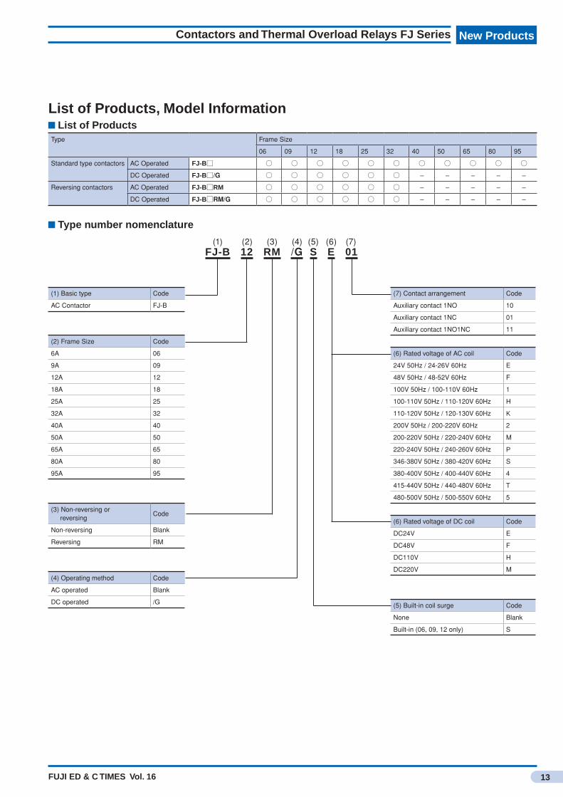
Type number nomenclature
(1) Basic type Code
AC Contactor FJ-B
(2) Frame Size Code
6A 06
9A 09
12A 12
18A 18
25A 25
32A 32
40A 40
50A 50
65A 65
80A 80
95A 95
(3) Non-reversing or reversing
Code
Non-reversing Blank
Reversing RM
(4) Operating method Code
AC operated Blank
DC operated /G
(7) Contact arrangement Code
Auxiliary contact 1NO 10
Auxiliary contact 1NC 01
Auxiliary contact 1NO1NC 11
(6) Rated voltage of AC coil Code
24V 50Hz / 24-26V 60Hz E
48V 50Hz / 48-52V 60Hz F
100V 50Hz / 100-110V 60Hz 1
100-110V 50Hz / 110-120V 60Hz H
110-120V 50Hz / 120-130V 60Hz K
200V 50Hz / 200-220V 60Hz 2
200-220V 50Hz / 220-240V 60Hz M
220-240V 50Hz / 240-260V 60Hz P
346-380V 50Hz / 380-420V 60Hz S
380-400V 50Hz / 400-440V 60Hz 4
415-440V 50Hz / 440-480V 60Hz T
480-500V 50Hz / 500-550V 60Hz 5
(6) Rated voltage of DC coil Code
DC24V E
DC48V F
DC110V H
DC220V M
(5) Built-in coil surge Code
None Blank
Built-in (06, 09, 12 only) S
FJ-B 12 RM /G S E 01(1) (2) (3) (4) (5) (6) (7)
List of Products, Model Information

FUJI ED & C TIMES Vol. 16
New ProductsNew Products
14
Magnetic starter FJ SeriesStarters with on-off pushbuttons
Models of “starters with pushbuttons convenient for motor ON/OFF” have been changed.
Features• Compact and simple operation –Provided with ON-OFF
pushbuttons, hence best suited for direct-on-line starting.• Superior motor protection – Built-in highly reliable thermal
overload relay is designed to give motor complete protection against overcurrent.
FJ-B25WP FJ-B32WP
Type number nomenclature
Types and ratings
FJ-B 12 W P MAIN AC380V 7A AC220V 1a
Basic type Auxiliary contact1a: 1NO
Rated coil voltageAC24V:24V 50Hz/24–26V 60HzAC48V:48V 50Hz/48–52V 60HzAC110V:100–110V 50Hz/110–120V 60HzAC220V:200–220V 50Hz/220–240V 60HzAC240V:220–240V 50Hz/240–260V 60HzAC380V:346–380V 50Hz/380–420V 60HzAC400V:380–400V 50Hz/400–440V 60HzAC415V:380–415V 50Hz/415–440V 60HzAC440V:415–440V 50Hz/440–480V 60Hz
Ampere setting range(See the next page.)
Motor starter
With on-off pushbuttons
Main circuit voltageAC110VAC200VAC220VAC240VAC380V
Frame size09: 9A12: 12A18: 18A25: 25A32: 32A
AC400VAC415VAC440VAC500VAC600V
Max. motor capacity (kW) Rated operational current (A) Auxiliary contact Enclosure material
Standard
Type Combined thermal overload relaySingle-
phase3-phase Single-
phase3-phase
110V 200V 380V 600V 110V 200V 380V 600V240V 440V 690V 240V 440V 690V
0.4 2.2 4 4 9 9 9 5 1NO Plastic FJ-B09WP TK12B0.5 3 5.5 5.5 12 12 12 6 1NO Plastic FJ-B12WP TK12B0.6 4 7.5 7.5 18 18 18 7 1NO Plastic FJ-B18WP TK18B0.8 5.5 11 7.5 22 25 25 9 1NO Plastic FJ-B25WP TK32B1.2 7.5 15 7.5 32 32 32 10 1NO Steel FJ-B32WP TK32B
Note: Auxiliary contact and surge suppressor are optional accessories. (Please refer to the nextparagraphs.)
FUJI ED & C TIMES Vol. 16
New Products
15
Magnetic starter FJ Series, Starters with on-off pushbuttons
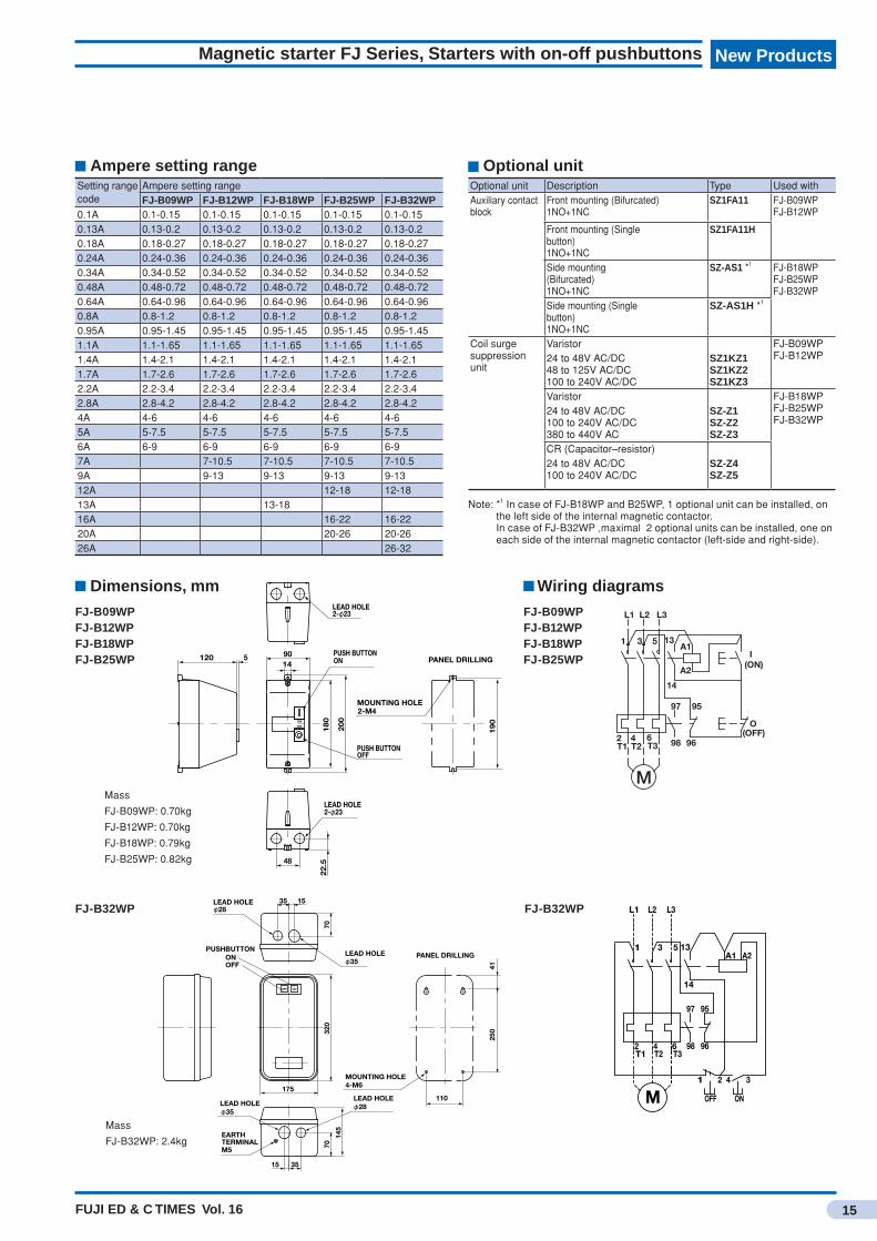
Ampere setting rangeSetting range code
Ampere setting rangeFJ-B09WP FJ-B12WP FJ-B18WP FJ-B25WP FJ-B32WP
0.1A 0.1-0.15 0.1-0.15 0.1-0.15 0.1-0.15 0.1-0.150.13A 0.13-0.2 0.13-0.2 0.13-0.2 0.13-0.2 0.13-0.20.18A 0.18-0.27 0.18-0.27 0.18-0.27 0.18-0.27 0.18-0.270.24A 0.24-0.36 0.24-0.36 0.24-0.36 0.24-0.36 0.24-0.360.34A 0.34-0.52 0.34-0.52 0.34-0.52 0.34-0.52 0.34-0.520.48A 0.48-0.72 0.48-0.72 0.48-0.72 0.48-0.72 0.48-0.720.64A 0.64-0.96 0.64-0.96 0.64-0.96 0.64-0.96 0.64-0.960.8A 0.8-1.2 0.8-1.2 0.8-1.2 0.8-1.2 0.8-1.20.95A 0.95-1.45 0.95-1.45 0.95-1.45 0.95-1.45 0.95-1.451.1A 1.1-1.65 1.1-1.65 1.1-1.65 1.1-1.65 1.1-1.651.4A 1.4-2.1 1.4-2.1 1.4-2.1 1.4-2.1 1.4-2.11.7A 1.7-2.6 1.7-2.6 1.7-2.6 1.7-2.6 1.7-2.62.2A 2.2-3.4 2.2-3.4 2.2-3.4 2.2-3.4 2.2-3.42.8A 2.8-4.2 2.8-4.2 2.8-4.2 2.8-4.2 2.8-4.24A 4-6 4-6 4-6 4-6 4-65A 5-7.5 5-7.5 5-7.5 5-7.5 5-7.56A 6-9 6-9 6-9 6-9 6-97A 7-10.5 7-10.5 7-10.5 7-10.59A 9-13 9-13 9-13 9-1312A 12-18 12-1813A 13-1816A 16-22 16-2220A 20-26 20-2626A 26-32
Optional unitOptional unit Description Type Used withAuxiliary contact block
Front mounting (Bifurcated) 1NO+1NC
SZ1FA11 FJ-B09WPFJ-B12WP
Front mounting (Single button) 1NO+1NC
SZ1FA11H
Side mounting (Bifurcated) 1NO+1NC
SZ-AS1 *1 FJ-B18WPFJ-B25WPFJ-B32WP
Side mounting (Single button) 1NO+1NC
SZ-AS1H *1
Coil surge suppression unit
Varistor FJ-B09WPFJ-B12WP24 to 48V AC/DC
48 to 125V AC/DC100 to 240V AC/DC
SZ1KZ1SZ1KZ2SZ1KZ3
Varistor FJ-B18WPFJ-B25WPFJ-B32WP
24 to 48V AC/DC100 to 240V AC/DC380 to 440V AC
SZ-Z1SZ-Z2SZ-Z3
CR (Capacitor–resistor)24 to 48V AC/DC100 to 240V AC/DC
SZ-Z4SZ-Z5
Note: *1 In case of FJ-B18WP and B25WP, 1 optional unit can be installed, on the left side of the internal magnetic contactor.
In case of FJ-B32WP ,maximal 2 optional units can be installed, one on each side of the internal magnetic contactor (left-side and right-side).
LEAD HOLE2-φ23
5120 PUSH BUTTONON
LEAD HOLE2-φ23
PUSH BUTTON
22
.548
PANEL DRILLING
MOUNTING HOLE2-M4
19
0
200
18
0
1490
OFF
ON
OFF
Dimensions, mm
FJ-B09WPFJ-B12WPFJ-B18WPFJ-B25WP
Mass
FJ-B09WP: 0.70kg
FJ-B12WP: 0.70kg
FJ-B18WP: 0.79kg
FJ-B25WP: 0.82kg
Wiring diagrams
FJ-B09WPFJ-B12WPFJ-B18WPFJ-B25WP
6T3
4T2
9597
98
13A1
O
I
14
96
A2
L1 L3L2
(OFF)
(ON)
1 3 5
2T1
M
FJ-B32WP FJ-B32WP
PANEL DRILLINGONOFF
PUSHBUTTON
15 35
70
145
320
70
1535
EARTHTERMINALM5
MOUNTING HOLE4-M6
LEAD HOLEφ35
LEAD HOLEφ28
LEAD HOLEφ28
LEAD HOLEφ35
41
110
250
OFF ON
175
M3421
ONOFF
T3T2T142 6 98 96
9597
A2A1
14
1 53
L3L2L1
13
Mass
FJ-B32WP: 2.4kg
FUJI ED & C TIMES Vol. 16
New ProductsNew Products
16
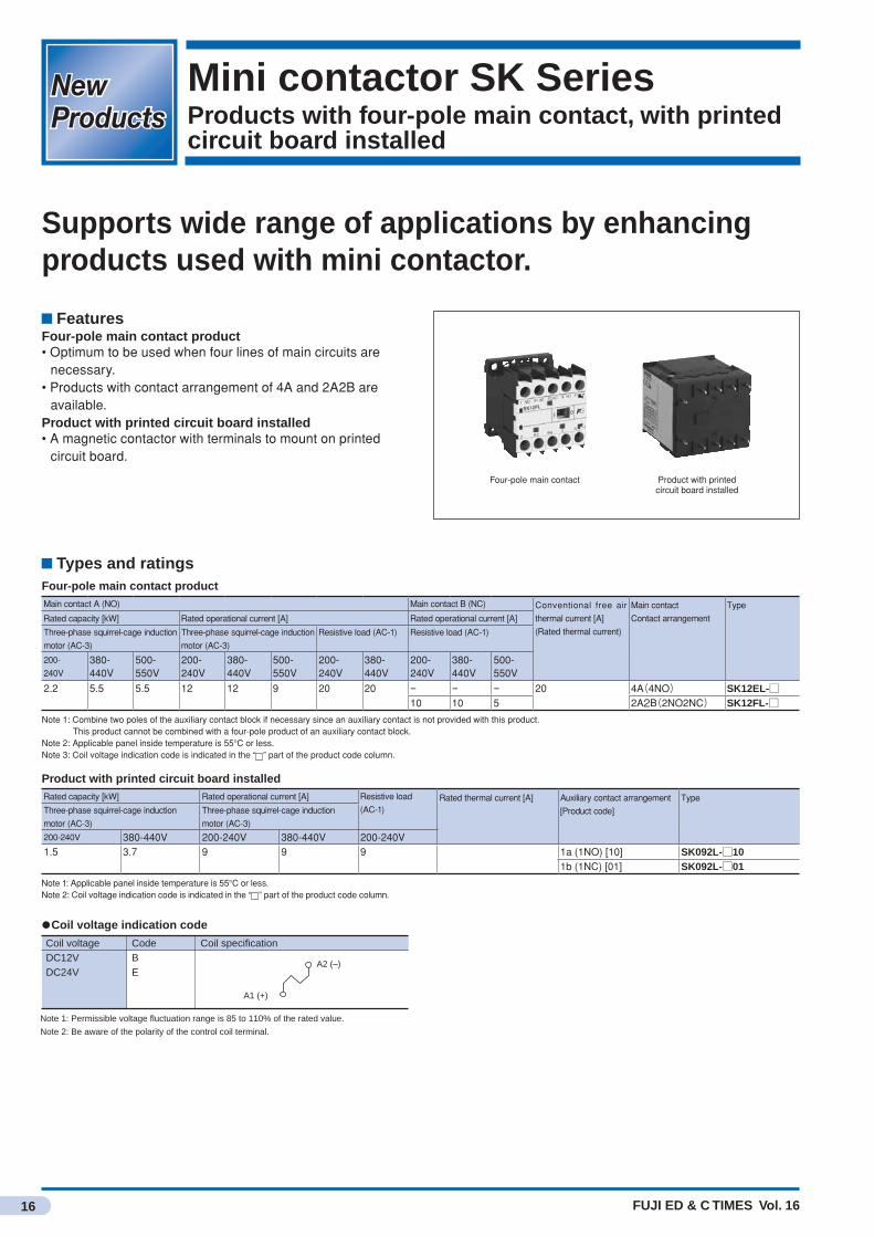
Mini contactor SK SeriesProducts with four-pole main contact, with printed circuit board installed
Supports wide range of applications by enhancing products used with mini contactor.
FeaturesFour-pole main contact product• Optimum to be used when four lines of main circuits are
necessary.• Products with contact arrangement of 4A and 2A2B are
available.Product with printed circuit board installed• A magnetic contactor with terminals to mount on printed
circuit board.
Types and ratingsFour-pole main contact productMain contact A (NO) Main contact B (NC) Conventional free air
thermal current [A]
(Rated thermal current)
Main contact
Contact arrangement
Type
Rated capacity [kW] Rated operational current [A] Rated operational current [A]
Three-phase squirrel-cage induction
motor (AC-3)
Three-phase squirrel-cage induction
motor (AC-3)
Resistive load (AC-1) Resistive load (AC-1)
200-
240V380-440V
500-550V
200-240V
380-440V
500-550V
200-240V
380-440V
200-240V
380-440V
500-550V
2.2 5.5 5.5 12 12 9 20 20 − − − 20 4A(4NO) SK12EL-□10 10 5 2A2B(2NO2NC) SK12FL-□
Note 1: Combine two poles of the auxiliary contact block if necessary since an auxiliary contact is not provided with this product. This product cannot be combined with a four-pole product of an auxiliary contact block.Note 2: Applicable panel inside temperature is 55°C or less.Note 3: Coil voltage indication code is indicated in the “ ” part of the product code column.
Product with printed circuit board installedRated capacity [kW] Rated operational current [A] Resistive load
(AC-1)Rated thermal current [A] Auxiliary contact arrangement
[Product code]
TypeThree-phase squirrel-cage induction
motor (AC-3)
Three-phase squirrel-cage induction
motor (AC-3)
200-240V 380-440V 200-240V 380-440V 200-240V1.5 3.7 9 9 9 1a (1NO) [10] SK092L-□10
1b (1NC) [01] SK092L-□01
Note 1: Applicable panel inside temperature is 55°C or less.Note 2: Coil voltage indication code is indicated in the “ ” part of the product code column.
●Coil voltage indication code
Note 1: Permissible voltage fluctuation range is 85 to 110% of the rated value.
Note 2: Be aware of the polarity of the control coil terminal.
CodeB E
Coil specification
A1 (+)
A2 (–)
Coil voltage DC12VDC24V
Four-pole main contact Product with printed circuit board installed

FUJI ED & C TIMES Vol. 16
New Products
17
Mini contactor SK Series, Products with four-pole main contact, with printed circuit board installed
SK092L type
4.25 8.7 8.7 8.7 10.75
22.2
31
47 4.5
41
45
22.2
31
4.25 8.7 8.7 8.7 10.75
1.3
1
1
1.3 134/L33/L21/L1
146/T32/T1 4/T2 A1 (+)
Printed circuit board processing dimensions (dimensions viewed from mounting side)
A2 (–) 10-∅2.2(Through hole on both sides)
Auxiliary
contact
1a
(1NO)
1b
(1NC)
1 3 5 13
2 4 6 14
A2 (–)
1 3 5 21
2 4 6 22
A1 (+)
A2 (–)
A1 (+)
Contact arrangement
diagram
SK12EL typeSK12FL type
Type
(Contact arrangement)
SK12EL
(4A)
SK12FL
(2A2B)
1/L1 3/L2 5/L3 7/L4
2/T1 4/T2 6/T3 8/T4
A2(–)
A1(+)
1 R1 R3 3
2 R2 R4 4 A2(–)
A1(+)
Contact arrangement
diagram
(34) *1
(17) *26
TerminalM3.5
61 (When rail height is 15)
3649
7.7
45
8.7
48 31
Coil terminalM3.5
Mounting hole 2×M4 35
*1 When auxiliary contact block (SZ1KA□) (front mounting, 2-pole) is attached (4-pole product cannot be attached)*2 When auxiliary contact block (SZ1FA□) (front mounting) is attached
Panel drilling
40
●Mounting screw: 2-M4Mount using two mounting holes that are in a diagonal line.
ーA2
+A1
T48
L47
2 T1 4 T2 6 T3
L35L23L11
Dimensions, mm
FUJI ED & C TIMES Vol. 16
New ProductsNew Products
18
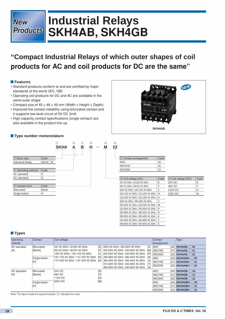
Industrial RelaysSKH4AB, SKH4GB
“Compact Industrial Relays of which outer shapes of coil products for AC and coil products for DC are the same”
Features• Standard products conform to and are certified by major
standards of the world (IEC, GB)• Operating coil products for DC and AC are available in the
same outer shape• Compact size of 45 × 48 × 49 mm (Width × Height × Depth)• Improved the contact reliability using bifurcated contact and
it supports low-level circuit of 5V DC 3mA• High capacity contact specifications (single contact) are
also available in the product line-up
SKH4AB
Types
Type number nomenclature
SKH4 A B H M 22-① ② ① ③ ④ ⑤
① Basic type CodeIndustrial Relay SKH4□B
⑤ Contact arrangement4NO3NO1NC2NO2NC
Code403122
④ Coil voltage (AC)24V AC 50Hz / 24-26V AC 60Hz48V AC 50Hz / 48-52V AC 60Hz100V AC 50Hz / 100-110V AC 60Hz100-110V AC 50Hz / 110-120V AC 60Hz110-120V AC 50Hz / 120-130V AC 60Hz200V AC 50Hz / 200-220V AC 60Hz200-220V AC 50Hz / 220-240V AC 60Hz220-240V AC 50Hz / 240-260V AC 60Hz346-380V AC 50Hz / 380-420V AC 60Hz380-400V AC 50Hz / 400-440V AC 60Hz415-440V AC 50Hz / 440-480V AC 60Hz480-500V AC 50Hz / 500-550V AC 60Hz
CodeEF1HK2MPS4T5
④ Coil voltage (DC)24V DC48V DC110V DC220V DC
CodeEFHM
② Operating method CodeAC operated ADC operated G
③ Contact form CodeBifurcated BlankSingle button H
Operating method
Contact Coil voltage Contact arrangement
Type
AC operated[A]
Bifurcated[Blank]
24V AC 50Hz / 24-26V AC 60Hz48V AC 50Hz / 48-52V AC 60Hz100V AC 50Hz / 100-110V AC 60Hz100-110V AC 50Hz / 110-120V AC 60Hz110-120V AC 50Hz / 120-130V AC 60Hz
[E][F][1][H][K]
200V AC 50Hz / 200-220V AC 60Hz200-220V AC 50Hz / 220-240V AC 60Hz220-240V AC 50Hz / 240-260V AC 60Hz346-380V AC 50Hz / 380-420V AC 60Hz380-400V AC 50Hz / 400-440V AC 60Hz415-440V AC 50Hz / 440-480V AC 60Hz480-500V AC 50Hz / 500-550V AC 60Hz
[2][M][P][S][4][T][5]
4NO [40] SKH4AB-□ 403NO1NC [31] SKH4AB-□ 312NO2NC [22] SKH4AB-□ 22
Single button[H]
4NO [40] SKH4ABH-□ 403NO1NC [31] SKH4ABH-□ 312NO2NC [22] SKH4ABH-□ 22
DC operated[G]
Bifurcated[Blank]
24V DC48V DC110V DC220V DC
[E][F][H][M]
4NO [40] SKH4GB-□ 403NO1NC [31] SKH4GB-□ 312NO2NC [22] SKH4GB-□ 22
Single button[H]
4NO [40] SKH4GBH-□ 403NO1NC [31] SKH4GBH-□ 312NO2NC [22] SKH4GBH-□ 22
Note: The figure inside the square brackets “[ ]” indicates the code.
FUJI ED & C TIMES Vol. 16
New Products
19
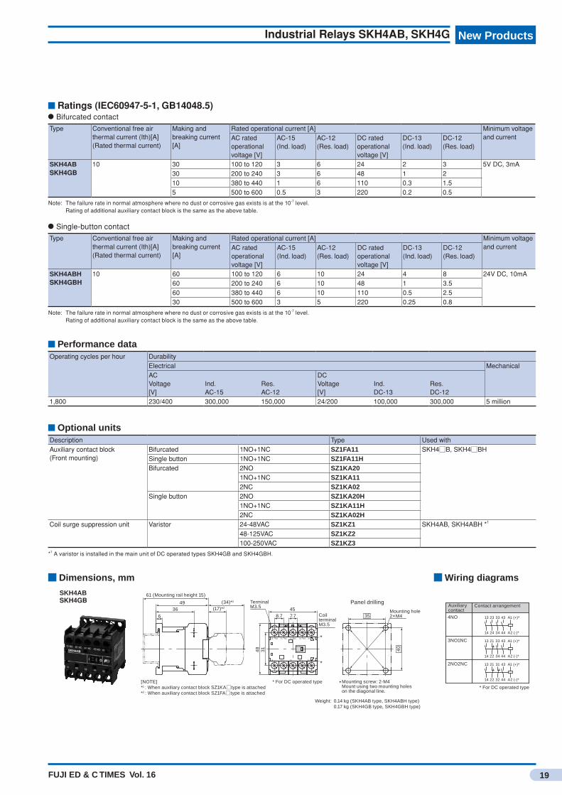
Industrial Relays SKH4AB, SKH4G
Ratings (IEC60947-5-1, GB14048.5) Bifurcated contact
Type Conventional free air thermal current (Ith)[A](Rated thermal current)
Making and breaking current [A]
Rated operational current [A] Minimum voltage and currentAC rated
operational voltage [V]
AC-15(Ind. load)
AC-12(Res. load)
DC rated operational voltage [V]
DC-13(Ind. load)
DC-12(Res. load)
SKH4ABSKH4GB
10 30 100 to 120 3 6 24 2 3 5V DC, 3mA30 200 to 240 3 6 48 1 210 380 to 440 1 6 110 0.3 1.55 500 to 600 0.5 3 220 0.2 0.5
Note: The failure rate in normal atmosphere where no dust or corrosive gas exists is at the 10-7 level. Rating of additional auxiliary contact block is the same as the above table.
Single-button contact
Type Conventional free air thermal current (Ith)[A](Rated thermal current)
Making and breaking current [A]
Rated operational current [A] Minimum voltage and currentAC rated
operational voltage [V]
AC-15(Ind. load)
AC-12(Res. load)
DC rated operational voltage [V]
DC-13(Ind. load)
DC-12(Res. load)
SKH4ABHSKH4GBH
10 60 100 to 120 6 10 24 4 8 24V DC, 10mA60 200 to 240 6 10 48 1 3.560 380 to 440 6 10 110 0.5 2.530 500 to 600 3 5 220 0.25 0.8
Note: The failure rate in normal atmosphere where no dust or corrosive gas exists is at the 10-7 level. Rating of additional auxiliary contact block is the same as the above table.
Optional unitsDescription Type Used withAuxiliary contact block(Front mounting)
Bifurcated 1NO+1NC SZ1FA11 SKH4□B, SKH4□BHSingle button 1NO+1NC SZ1FA11H Bifurcated 2NO SZ1KA20
1NO+1NC SZ1KA112NC SZ1KA02
Single button 2NO SZ1KA20H1NO+1NC SZ1KA11H2NC SZ1KA02H
Coil surge suppression unit Varistor 24-48VAC SZ1KZ1 SKH4AB, SKH4ABH *1
48-125VAC SZ1KZ2100-250VAC SZ1KZ3
*1 A varistor is installed in the main unit of DC operated types SKH4GB and SKH4GBH.
Performance dataOperating cycles per hour Durability
Electrical MechanicalACVoltage[V]
Ind.AC-15
Res.AC-12
DCVoltage[V]
Ind. DC-13
Res.DC-12
1,800 230/400 300,000 150,000 24/200 100,000 300,000 5 million
Dimensions, mm Wiring diagrams
SKH4ABSKH4GB (34)*1
(17)*2
Mounting hole2×M4 6
40
35CoilterminalM3.5
TerminalM3.5
61 (Mounting rail height 15)
3649
7.7
48 31
458.7
* For DC operated type
Weight: 0.14 kg (SKH4AB type, SKH4ABH type) 0.17 kg (SKH4GB type, SKH4GBH type)
[NOTE]*1 : When auxiliary contact block SZ1KA□type is attached*2 : When auxiliary contact block SZ1FA□type is attached
*
*
Mounting screw: 2-M4Mount using two mounting holes on the diagonal line.
Panel drilling
-A244322214
+A1NO43NC31NC2113 NO
34
33
A2 (-)*
A1 (+)*13 21 31 43
322214 44
2NO2NC
4414 22
432113
* For DC operated type
A1 (+)*
A2 (-)*
44
43332313
14 24 34
Auxiliarycontact
Contact arrangement
4NO
3NO1NC
A2 (-)*
A1 (+)*
FUJI ED & C TIMES Vol. 16
New ProductsNew Products
20
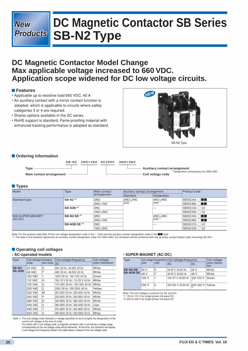
DC Magnetic Contactor SB SeriesSB-N2 Type
DC Magnetic Contactor Model ChangeMax applicable voltage increased to 660 VDC. Application scope widened for DC low voltage circuits.
Features• Applicable up to resistive load 660 VDC, 40 A• An auxiliary contact with a mirror contact function is
adopted, which is applicable to circuits where safety categories 3 or 4 are required.
• Shares options available in the SC series. • RoHS support is standard. Fame-proofing material with
enhanced tracking performance is adopted as standard.
SB-N2 Type
Types
Operating coil voltages
Ordering information S B - N 2 2 N O + 1N C A C 2 0 0 V 4 N O + 4 N C
Type
Main contact arrangement
Auxiliary contact arrangement
Coil voltage code* Designation unnecessary for 2NO+2NC
Model Type Main contact arrangement
Auxiliary contact arrangement Product codeStandard Designation
Standard type SB-N2 *2 2NO 2NO+2NC[22] *1
4NO+4NC[44] *1
SB35CAA-□■■2NO+1NC SB35CBA-□■■
SB-N2B *2 2NC — SB35CCA-□ 221NO+2NC SB35CDA-□ 22
With SUPER-MAGNET(AC/DC)
SB-N2/SE *2 2NO 4NO+4NC[44] *1
SB35CAS-□■■2NO+1NC SB35CBS-□■■
SB-N2B/SE *2 2NC — SB35CCS-□ 221NO+2NC SB35CDS-□ 22
Note: For the product code field, fill the coil voltage designation code in the □ field and the auxiliary contact designation code in the ■■ field.*1: The data in the brackets represents an auxiliary contact designation code. For 4NO+4NC, the contactor will be combined with two auxiliary contact blocks (side mounting) SZ-AS1.
• AC-operated modelsType Coil voltage
codeDesigna-tion code
Coil voltage/frequency Coil voltage color indicationAC
SB-N2SB-N2B
24 VAC E 24V, 50 Hz / 24-26V, 60 Hz White48 VAC F 48V, 50 Hz / 48-52V, 60 Hz White100 VAC 1 100V, 50 Hz / 100-110V, 60 Hz Green110 VAC H 100-110 V, 50 Hz / 110-120 V, 60 Hz White120 VAC K 110-120V, 50 Hz / 120-130V, 60 Hz White200 VAC 2 200V, 50 Hz / 200-220V, 60 Hz Yellow220 VAC M 200-220V, 50 Hz / 220-240V, 60 Hz White240 VAC P 220-240V, 50 Hz / 240-260V, 60 Hz White380 VAC S 346-380V, 50 Hz / 380-420V, 60 Hz White400 VAC 4 380-400V, 50 Hz / 400-440V, 60 Hz Lilac440 VAC T 415-440V, 50 Hz / 440-480V, 60 Hz White500 VAC 5 480-500V, 50 Hz / 500-550V, 60 Hz White
Note 1: The coil voltage code indicates a voltage specified so as to simplify the designation of the control coil voltage at the time of order.For orders with a coil voltage code, a magnetic contactor with a coil having a voltage range corresponding to the coil voltage code will be delivered. At this time, the contactor will display a coil voltage and frequency listed in the table above, instead of the coil voltage code.
• SUPER MAGNET (AC/DC)Type Coil voltage
codeDesignation code
Coil voltage/frequency Coil voltage color indica-tion
AC DC
SB-N2/SESB-N2B/SE
24 V E 24-25 V, 50/60 Hz 24 V White48 V F 48-50 V, 50/60 Hz 48 V White100 V 1 100-127 V, 50/60 Hz 100-120 V
*1Green
200 V 2 200-250 V, 50/60 Hz 200-240 V *2
Yellow
Note: The coil voltage is common for AC and DC.*1: 100 to 110 V for single-phase full-wave DC.*2: 200 to 220 V for single-phase full-wave DC.

FUJI ED & C TIMES Vol. 16
New Products
21
DC Magnetic Contactor SB Series SB-N2 Type
Main contact ratings• Main contacts 2NO, 2NO+1NC:Main contact NO ratings (two serial contacts)Type Max. motor capacity (kW) Rated operational current (A) Conventional free air thermal current
(rated thermal current)(A)
Class DC2, 4(JEM1038)(DC motor, L/R ≤ 15ms.)
Class DC2, 4(JEM1038)(DC motor, L/R ≤ 15ms.)
Class DC1(JEM1038)(Resistive, L/R ≤ 1ms.)
110 V 220 V 440 V 550 V 110 V 220 V 440 V 550 V 110 V 220 V 440 V 550 V 660 VSB-N2SB-N2/SE
3.7 5.5 7.5 5.5 40 35 20 15 60 60 60 50 40 60
Notes: Conforming to class DC2 and DC4, JEM 1038DC2: For shunt-wound motors: Starting, switching off during running. The starting current is less than 2.5 times the rated current.DC4: For series-wound motors: Starting, switching off during running. The starting current is less than 2.5 times the rated current.
Main contact NC ratings (single contact)
Type Dynamic brake *1 Conventional free air thermal current (rated thermal current)(A)Making current (A) Time rating (sec) Operating cycles per hour
SB-N2SB-N2/SE
60 3 600 50
*1: The electrical switching durability test consists of 250,000 times or more under a double closed circuit and no-voltage open contact conditions
• Main contacts 2NC, 1NO+2NC:Main contact NC ratings (two serial contacts)
Type Max. motor capacity (kW) Rated operational current (A) Conventional free air thermal current(rated thermal current)(A)Class DC2, 4(JEM1038)
(DC motor, L/R ≤ 15ms.)Class DC2, 4(JEM1038)(DC motor, L/R ≤ 15ms.)
Class DC1(JEM1038)(Resistive, L/R ≤ 1ms.)
110 V 220 V 440 V 110 V 220 V 440 V 110 V 220 V 440 V 550 V 660 VSB-N2BSB-N2B/SE
2.2 3.7 — 30 20 — 30 25 10 5 — 50
Main contact NO ratings (single contact)
Type Max. motor capacity (kW) Rated operational current (A) Conventional free air thermal current(rated thermal current)(A)Class DC2, 4(JEM1038) (DC motor, L/R ≤ 15ms.) Class DC2, 4(JEM1038) (DC motor, L/R ≤ 15ms.)
110 V 220 V 440 V 110 V 220 V 440 VSB-N2BSB-N2B/SE
1.5 2.2 — 20 15 — 60
Auxiliary contact ratingsConventional free air thermal current(rated thermal current)(A)
Making and breaking current at AC(A)
Rated operational current (A) Minimum voltage and current *1AC DC
Voltage (V) AC-15 (Ind. load) AC-12 (Res. load) Voltage (V) DC-13 *3 (Ind. load) DC-12 (Res. load)
10 60 100 to 120 6 10 24 3 5 5 VDC, 3 mA30 200 to 240 3 8 48 1.5 315 380 to 440 1.5 5 110 0.55 2.512 500 to 600 1.2 5 220 0.27 1
*1: The failure rate is level 10-7 in a usual atmosphere without dust and corrosive gas. *2: The rating of the auxiliary contact block is the same as in the table above.*3: Time constant L/R = 70 ms:
PerformancesType Main contact Rated operational
voltage(V)
Rated operational current(A)
Operating cycles per hour
Durability
Mechanical Electrical Class DC2, 4(JEM1038)(DC motor, L/R ≤ 15ms.)
SB-N2 Contact NO (two serial contacts)
220 35 1200 2.5 million 500, 000SB-N2/SE 440 20SB-N2B Contact NC
(two serial contacts)110 30 1200 2.5 million 250,000
SB-N2B/SE 220 20Contact NO (single contact)
110 20 1200 2.5 million 250,000220 15
Coil Characteristics• AC-operated models (SB-N2, N2B)Power consumption Watt lossInrush Sealed200 V, 50 Hz 220 V, 60 Hz 200 V, 50 Hz 220 V, 60 Hz 200 V, 50 Hz 220 V, 60 Hz120 VA 135 VA 12.7 VA 12.4 VA 3.6 W 3.8 W
Note 1: Coil rating: 200 V, 50 Hz / 220-220 V, 60 HzNote 2: Variation range of operating voltage: 85 to 110% of rated voltage
• SUPER MAGNET (SB-N2/SE, N2B/SE)Power consumption Watt lossInrush Sealed200 V, 50 Hz 220 V, 60 Hz 200 VDC 200 V, 50 Hz 220 V, 60 Hz 200 VDC 200 V, 50 Hz 220 V, 60 Hz 200 VDC105 VA 130 VA 125 W 3.5 VA 4.2 VA 2.4 W 2.8 W 3.2 W 2.4 W
Note 1: Coil rating: 200-250 V, 50 Hz / 60 Hz, 200-240 VDCNote 2: Variation range of operating voltage: 80 to 110% of rated voltage

New Products
22 FUJI ED & C TIMES Vol. 16
DC Magnetic Contactor SB Series SB-N2 Type
Standard compliance
Type Compliant standards
Certified standards
JEM IEC UL CSAJapan International USA CanadaJEM
SB-N2, SB-N2/SE ◎ ◎ ◎ *1 ◎ *1
SB-N2B, SB-N2B/SE ◎ ◎ — —
Note: Applicable ◎: Standard product is compliant and certified*1: Under application
• Changing the auxiliary contact terminal numberEnsure that the terminal numbers for auxiliary contact differ from that for conventional contacts.The number in the parentheses indicates a terminal number of old type SB-2N.
13 43
31
32
44
(23)
(41)
(42)
(24)
21
22
(31)
(32)
14
• The main contact terminals have positive and negative polarities. Connect cables correctly in terms of their polarities. (Refer to the example on the right.)
• It is ideal to mount the contactor on a vertical plane. However, if mounting the contactor on a sloping surface, ensure that the slope is within ±30 degree longitudinally and vertically.
• When mounting the contactor, ensure that an arc space of more than the value shown in the outline drawing is provided in front of the arc-extinguishing chamber. (This is unnecessary if the contactor is not used for shutting off currents.)
Note: Caution on use
Note: • R: resistance for dynamic brake • For products with main contact 2NO, contact 1NC No. 3, 4 are omitted.
(example: product with connect 2NO+1NC)
1 3 5
A1 A2
2 4 6
43 31
44 32
13 21
14 22
R Power-on direction
H AM
Options
Option Combination of options
Main contact arrangement
Type 2NO 2NO+1NC 2NC 1NO+2NC
Auxiliary contact block (side mounting) SZ-AS1 ○ —Coil driving unit (relay type) for IC output *1 SZ-CD3 ○ ○Coil driving unit (SSR type) for IC output *1 SZ-CD4 ○ ○Coil-surge suppression unit *1 SZ-Z31 to Z35 ○ ○Live-section cover *1 SZ-N1J ○ ○Terminal cover SZ-T24 ○ ○*1: Unable to combine with the mechanical latch model and SB-N2/VS Type.*2: ○: combination OK, —: combination disabled
Comparison between new and old types
Model Old type New type Compatible mounting methodType Main contact
arrangementType Main contact
arrangementStandard type SB-2N 2NO SB-N2 2NO Yes
SB-2NB 2NO+1NC 2NO+1NC Yes2NO SB-N2B 2NC Yes1NO+2NC 1NO+2NC Yes
With super magnet
SB-2N/SE 2NO SB-N2/SE 2NO YesSB-2NB/SE 2NO+1NC 2NO+1NC Yes
2NC SB-N2B/SE 2NC Yes1NO+2NC 1NO+2NC Yes

23FUJI ED & C TIMES Vol. 16
New ProductsDC Magnetic Contactor SB Series SB-N2 Type
Dimensions, mm
SB-N2 [SB35C□ A-....]SB-N2B [SB35C□ A-....]
SB-N2/SE [SB35C□ S-....]SB-N2B/SE [SB35C□ S-....]
Mass: 0.59 kg
Mass: 0.87 kg
*1: In cases where auxiliary contact block (side mounting) is installed (SB-N2B and N2B/SE are not allowed)
*2: There are no terminals 3/4 in the case of main contact 2NO or 2NC.
CautionUse two diagonal holes for installation of the contactor.(i) (60 to) 65 x 70: compatible with SB-2N, 2NB(ii) 45 (to 50) x 75: IEC mounting hole
Contact arrangementSB-N2 (2NO), SB-N2/SE (2NO)
SB-N2(2A)
-+
+-
54 62 14 22 44 32 84 72
A2A1718331435121136153
2 6
※3 ※3SB-N2B (2NC), SB-N2B/SE (2NC)
SB-N2B(2B)
-+
+-
14 22 44 32
A2A13143512113
2 6
SB-N2 (2NO+1NC), SB-N2/SE (2NO+1NC)
7284
7183
3244
3143
54 62 14 22
21136153+
-4
3
+ -2 6
+-51
SB-N2(2A1B)
※3※3
A1 A2
SB-N2B (1NO+2NC), SB-N2B/SE (1NO+2NC)
+
-4
3
+ -2 6
+-51
SB-N2B(1A2B)
13 21 43 31A1 A2
32442214
Note 1: *3: In the case of auxiliary contact 4NO+4NCNote 2: Combination with auxiliary contact block (front mounting) is not allowed.
3244
4331
2214
1321
642
51 3
A2A1
Grounding metal
*1
M3.5
M5Main terminal
Aux. terminal
M3.5Coil terminal
1
2
Mounting hole2-M4
30 at minimum
5.5
14.3
(99)*1
65.5
106 (rail height: 15)
10.5
96
12.4 16.5
8759.5
74
6.5
75
970
45 (~50)
(60~) 65
※2
*1
*2
Panel drilling
*1 Mounting hole2-M4
Coil terminalM3.5
Aux.terminalM3.5
Main terminalM5
(rail height: 15)Panel drilling
7024
(60~)65
112
59.5
29
16.512.4
74(99)*1
*2
*1
*25.5
140130
4499
3244
4331
2214
1321
A2A1
642
531
Grounding metal
30 at minimum
*1: In cases where auxiliary contact block (side mounting) is installed (SB-N2B and N2B/SE are not allowed)
*2: There are no terminals 3/4 in the case of main contact 2NO or 2NC.
FUJI ED & C TIMES Vol. 16
New ProductsNew Products
24
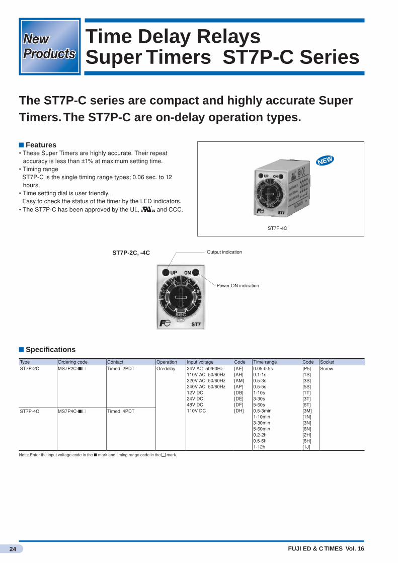
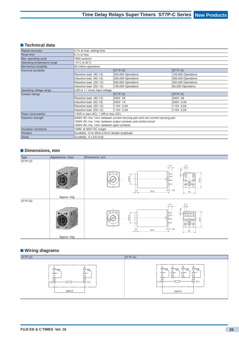
Time Delay RelaysSuper Timers ST7P-C Series
The ST7P-C series are compact and highly accurate Super Timers. The ST7P-C are on-delay operation types.
Features• These Super Timers are highly accurate. Their repeat
accuracy is less than ±1% at maximum setting time.• Timing range ST7P-C is the single timing range types; 0.06 sec. to 12
hours.• Time setting dial is user friendly. Easy to check the status of the timer by the LED indicators.• The ST7P-C has been approved by the UL, and CCC.
ST7P-4C
ST7P-2C, -4C Output indication
Power ON indication
Specifications
Type Ordering code Contact Operation Input voltage Code Time range Code SocketST7P-2C MS7P2C-■■ Timed: 2PDT On-delay 24V AC 50/60Hz
110V AC 50/60Hz220V AC 50/60Hz240V AC 50/60Hz12V DC24V DC48V DC110V DC
[AE][AH][AM][AP][DB][DE][DF][DH]
0.05-0.5s0.1-1s0.5-3s0.5-5s1-10s3-30s5-60s0.5-3min1-10min3-30min5-60min0.2-2h0.5-6h1-12h
[P5][1S][3S][5S][1T][3T][6T][3M][1N][3N][6N][2H][6H][1J]
Screw
ST7P-4C MS7P4C-■■ Timed: 4PDT
Note: Enter the input voltage code in the ■ mark and timing range code in the mark.
FUJI ED & C TIMES Vol. 16
New Products
25
Time Delay Relays Super Timers ST7P-C Series
Technical dataRepeat accuracy ±1% at max. setting timeReset time 0.1s or lessMax. operating cycle 1800 cycles/hOperating temperature range -10˚C to 50˚CMechanical durability 50 million operationsElectrical durability ST7P-2C ST7P-4C
Resistive load (AC-12) 200,000 Operations 120,000 OperationsInductive load (AC-15) 320,000 Operations 260,000 OperationsResistive load (DC-12) 500,000 Operations 260,000 OperationsInductive load (DC-13) 150,000 Operations 50,000 Operations
Operating voltage range 0.85 to 1.1 times input voltageContact ratings ST7P-2C ST7P-4C
Resistive load (AC-12) 240V 5A 240V 3AInductive load (AC-15) 220V 1A 220V 0.3AResistive load (DC-12) 110V 0.5A 110V 0.5AInductive load (DC-13) 110V 0.2A 110V 0.2A
Power consumption 1.9VA or less (AC), 1.2W or less (DC)Dielectric strength 2000V AC rms. 1min. between current carrying part and non current carrying part
1500V AC rms. 1min. between output contacts and control circuit 1000V AC rms. 1min. between open contacts
Insulation resistance 100MΩ at 500V DC megerVibration Durability: 10 to 55Hz,0.5mm double amplitudeShock Durability: 5 x 9.8 m/s2
Dimensions, mm
Wiring diagramsST7P-2C ST7P-4C
Type Appearance, mass Dimensions, mmST7P-2C
Approx. 45gST7P-4C
Approx. 45g
18.5
4 52.6 1.8
5.7 2.2
0.5
9
5
1
12
8
4
13 14
27.8
21
18.5
4 52.6 1.8
5.7 2.2
0.5
9
5
1
12
8
4
13 14
27.8
21
10
6
2
11
7
3
1
5
9
13
4
8
12
14
INPUT
(–) (+)
2
6
10
3
7
11
1
5
9
13
4
8
12
14(–) (+)
INPUT
FUJI ED & C TIMES Vol. 16
New ProductsNew Products
26
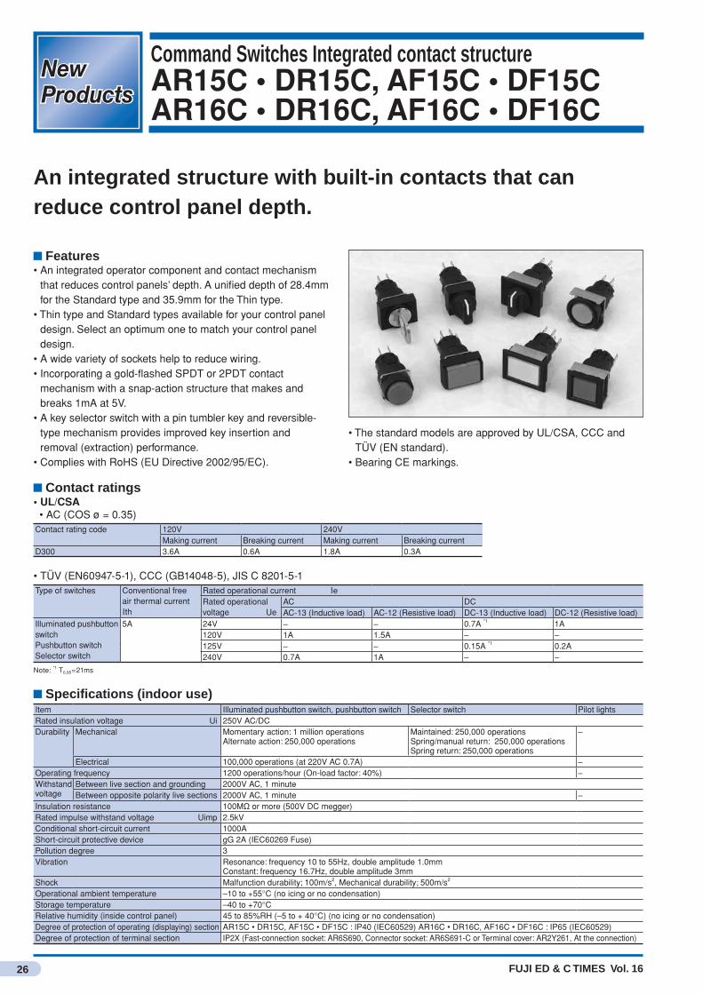
Command Switches Integrated contact structureAR15C • DR15C, AF15C • DF15CAR16C • DR16C, AF16C • DF16C
An integrated structure with built-in contacts that can reduce control panel depth.
Features• An integrated operator component and contact mechanism
that reduces control panels’ depth. A unified depth of 28.4mm for the Standard type and 35.9mm for the Thin type.
• Thin type and Standard types available for your control panel design. Select an optimum one to match your control panel design.
• A wide variety of sockets help to reduce wiring.• Incorporating a gold-flashed SPDT or 2PDT contact
mechanism with a snap-action structure that makes and breaks 1mA at 5V.
• A key selector switch with a pin tumbler key and reversible-type mechanism provides improved key insertion and removal (extraction) performance.
• Complies with RoHS (EU Directive 2002/95/EC).
Contact ratings• UL/CSA • AC (COS ø = 0.35)Contact rating code 120V 240V
Making current Breaking current Making current Breaking currentD300 3.6A 0.6A 1.8A 0.3A
• TÜV (EN60947-5-1), CCC (GB14048-5), JIS C 8201-5-1Type of switches Conventional free
air thermal current Ith
Rated operational current IeRated operational voltage Ue
AC DCAC-13 (Inductive load) AC-12 (Resistive load) DC-13 (Inductive load) DC-12 (Resistive load)
Illuminated pushbutton switchPushbutton switchSelector switch
5A 24V – – 0.7A *1 1A120V 1A 1.5A – –125V – – 0.15A *1 0.2A240V 0.7A 1A – –
Note: *1 T0.95=21ms
Specifications (indoor use)Item Illuminated pushbutton switch, pushbutton switch Selector switch Pilot lightsRated insulation voltage Ui 250V AC/DCDurability Mechanical Momentary action: 1 million operations
Alternate action: 250,000 operations Maintained: 250,000 operationsSpring/manual return: 250,000 operationsSpring return: 250,000 operations
–
Electrical 100,000 operations (at 220V AC 0.7A) –Operating frequency 1200 operations/hour (On-load factor: 40%) –Withstand voltage
Between live section and grounding 2000V AC, 1 minuteBetween opposite polarity live sections 2000V AC, 1 minute –
Insulation resistance 100MΩ or more (500V DC megger)Rated impulse withstand voltage Uimp 2.5kVConditional short-circuit current 1000AShort-circuit protective device gG 2A (IEC60269 Fuse)Pollution degree 3Vibration Resonance: frequency 10 to 55Hz, double amplitude 1.0mm
Constant: frequency 16.7Hz, double amplitude 3mmShock Malfunction durability; 100m/s2, Mechanical durability; 500m/s2
Operational ambient temperature –10 to +55°C (no icing or no condensation)Storage temperature –40 to +70°CRelative humidity (inside control panel) 45 to 85%RH (–5 to + 40°C) (no icing or no condensation)Degree of protection of operating (displaying) section AR15C • DR15C, AF15C • DF15C : IP40 (IEC60529) AR16C • DR16C, AF16C • DF16C : IP65 (IEC60529)Degree of protection of terminal section IP2X (Fast-connection socket: AR6S690, Connector socket: AR6S691-C or Terminal cover: AR2Y261, At the connection)
• The standard models are approved by UL/CSA, CCC and TÜV (EN standard).
• Bearing CE markings.
FUJI ED & C TIMES Vol. 16
New Products
27
Command Switches Integrated contact structure AR15C • DR15C, AF15C • DF15C, AR16C • DR16C, AF16C • DF16C
Specifications (Socket)Ietm Fast-connection socket Connector socket Socket for PC boardRated insulation voltage Ui 250V AC/DC 60V AC/DCConventional free air thermal current Ith 3A 5A 3ARated impulse withstand voltage Uimp 2.5kV 0.5kVWithstand voltage (Between live section and grounding) 2000V AC, 1minute 1000V AC, 1minuteInsulation resistance 100MΩ or more (500V DC megger)Operational ambient temperature –10 to +55°C (no icing or no condensation)Storage temperature –40 to +70°CRelative humidity 45 to 85%RH (–5 to + 40°C) (no icing or no condensation)Pollution degree 3
Contact reliabilityFUJI has confirmed that the product can be used in 1mA circuit conditions at 5V AC or DC. The operable range, however, may vary depending on the operational ambient conditions and type of load.
Lamp ratings and current consumption• Illuminated pushbutton switch, Pilot lightsApplied method Lamp operational voltage High-brightness LED lamp
Type Lamp rated voltage Current consumptionwithout transformer 12V DC DR6L695C-B 12V DC Green, Red, Amber, Blue: 9 to 10.5mA DC
White: 4.5 to 5.5mA DC24V DC DR6L695C-E 24V DC
Note: A box indicates the luminous color. For details, see the “Combination of Illuminated pushbutton / pilot light color and LED lamp luminous color”.
Combination of Illuminated pushbutton / pilot light color and LED lamp luminous colorIlluminated pushbutton / pilot light color (lens color)
Luminous color of high-brightnessLED lamp
Type TypeGreen G Green DR6L695C- GRed R Red DR6L695C- RWhite W White DR6L695C- PYellow Y White DR6L695C- POrange A Amber DR6L695C- ABlue S Blue DR6L695C- S
Note: *1 A box indicates the lamp operational voltage. For details, see the “Lamp ratings and current consumption”.
LED durabilityType of lamp Durability(reference) Judgment criterionLED lamp Approx. 30000h When the brightness is less than 50% of initial value.
Note: The durability of LED lamp is a mean value in all colors.
Standard approvedUL508 cUL File No.E44592CSA C22.2 No.14TÜV: EN60947-5-1 Pushbutton, Illuminated pushbutton: R50116757
Selector: R50116759Pilot lights: R50116762
CCC: GB14048.5 Switches (except pilot lights): 2013010305590653Pilot lights: 2013010305590652
Standard models approved by international standardsThe standard models of AR15C•DR15C, AF15C•DF15C series and AR16C•DR16C, AF16C•DF16C series of the ø16 Command Switches meet UL / CSA requirements, China Compulsory Certification (CCC) standards, and TÜV EN standards, thus ensuring easier direct or indirect export to North America and European countries with no safety standard concerns.
FUJI ED & C TIMES Vol. 16
New ProductsNew Products
28
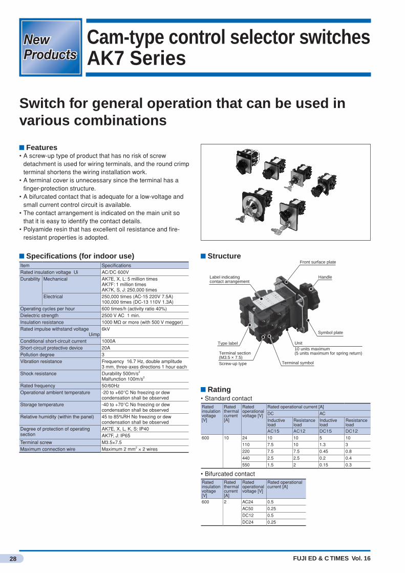
Cam-type control selector switchesAK7 Series
Switch for general operation that can be used in various combinations
Features• A screw-up type of product that has no risk of screw
detachment is used for wiring terminals, and the round crimp terminal shortens the wiring installation work.
• A terminal cover is unnecessary since the terminal has a finger-protection structure.
• A bifurcated contact that is adequate for a low-voltage and small current control circuit is available.
• The contact arrangement is indicated on the main unit so that it is easy to identify the contact details.
• Polyamide resin that has excellent oil resistance and fire-resistant properties is adopted.
Specifications (for indoor use)Item SpecificationsRated insulation voltage Ui AC/DC 600VDurability Mechanical AK7E, X, L: 5 million times
AK7F: 1 million timesAK7K, S, J: 250,000 times
Electrical 250,000 times (AC-15 220V 7.5A)100,000 times (DC-13 110V 1.3A)
Operating cycles per hour 600 times/h (activity ratio 40%)Dielectric strength 2500 V AC 1 min.Insulation resistance 1000 MΩ or more (with 500 V megger)Rated impulse withstand voltage Uimp
6kV
Conditional short-circuit current 1000AShort-circuit protective device 20APollution degree 3Vibration resistance Frequency 16.7 Hz, double amplitude
3 mm, three-axes directions 1 hour eachShock resistance Durability 500m/s2
Malfunction 100m/s2
Rated frequency 50/60HzOperational ambient temperature -20 to +60°C No freezing or dew
condensation shall be observedStorage temperature -40 to +70°C No freezing or dew
condensation shall be observedRelative humidity (within the panel) 45 to 85%RH No freezing or dew
condensation shall be observedDegree of protection of operating section
AK7E, X, L, K, S: IP40AK7F, J: IP65
Terminal screw M3.5×7.5Maximum connection wire Maximum 2 mm2 × 2 wires
StructureFront surface plate
Unit10 units maximum(5 units maximum for spring return)
Terminal symbol
Label indicating contact arrangement
Type label
Terminal section (M3.5 × 7.5)Screw-up type
Symbol plate
Handle
Rating• Standard contactRated insulation voltage [V]
Rated thermal current [A]
Rated operational voltage [V]
Rated operational current [A]
DC AC
Inductive load
Resistance load
Inductive load
Resistance load
AC15 AC12 DC15 DC12600 10 24 10 10 5 10
110 7.5 10 1.3 3
220 7.5 7.5 0.45 0.8
440 2.5 2.5 0.2 0.4
550 1.5 2 0.15 0.3
• Bifurcated contactRated insulation voltage [V]
Rated thermal current [A]
Rated operational voltage [V]
Rated operational current [A]
600 2 AC24 0.5
AC50 0.25
DC12 0.5
DC24 0.25

FUJI ED & C TIMES Vol. 16
New Products
29
Cam-type control selector switches AK7 Series
Types
Dimensions, mm
Appearance Basic type Mounting Number of element steps
AK7F1
AK7F1-M• Maintained type• With small handle
AK7F1-A• Spring return type• With small handle• Note 1
30φRing nut mounting
12345678910
AK7X1
AK7X1-M• Maintained type• With small handle
AK7X1-A• Spring return type• With small handle• Note 1
Flange mountingFlush mounting No front surface plate
12345678910
AK7E1
AK7E1-M• Maintained type• With small handle
AK7E1-A• Spring return type• With small handle• Note 1
Flange mountingFlush mounting With front surface plate
12345678910
(Note) Only standard products are described. * Number of simultaneous contacts is 5 or less (up to 5 elements)
AK7F1 (handle operation type)
AK7X1 (flush mounting with no front surface plate) AK7E1 (with flush mounting front surface plate)
13.3 12 17.13.6
M4 × 12 countersunk screw(Mounting screw for main unit’ s
front surface plate)
48
Mounting hole dimensions
LMounting panel 4.5 (max.)
38
4–φ4.5
φ8
48
SUS M2.6 × 4 tapping(Mounting screw for symbol plate)
M3 Depth 7
□5
6
23M3 × 15 three pieces
(Handle mounting screw)
□60□56
L dimension table
Number of elements 1 2 3 4 5 6 7 8 9 10L dimension (mm) 42.4 54.4 66.4 78.4 90.4 102.4 114.4 126.4 138.4 150.4
The dimension will be 17.5 mm longer than the dimensions described above for specifications that add a pulling operation.
(Note) There is no need to make a hole with a width of 4.8 mm when there is no key washer or when a symbol plate is not used.
13.3 12 17.13.6
□5
□60 48 48
M3 Depth 7
M4 × 10 three pieces (Main unit mounting screw)
Mounting hole dimensions
LMounting panel 4.5 (max.)
23M3 × 15 three pieces
(Handle mounting screw)
4–M448
4–φ4.5
φ8
48
38
L dimension table
Number of elements 1 2 3 4 5 6 7 8 9 10L dimension (mm) 42.4 54.4 66.4 78.4 90.4 102.4 114.4 126.4 138.4 150.4
The dimension will be 17.5 mm longer than the dimensions described above for specifications that add a pulling operation.
Mounting hole dimensions
φ30.54.8
33+0.5
0
+0.2 0
+0.5 0.0
13.3
Resin screw M4×16(Holding screw)
12 13.5 Mounting panel 0.8~6
20
M3 Depth 7
SS M3 × 15 three pieces(Handle mounting screw)
3449
L
L dimension table
Number of elements 1 2 3 4 5L dimension (mm) 38.8 50.8 62.8 74.8 86.8Number of elements 6 7 8 9 10L dimension (mm) 98.8 110.8 122.8 134.8 146.8
The dimension will be 17.5 mm longer than the dimensions described above for specifications that add a pulling operation.
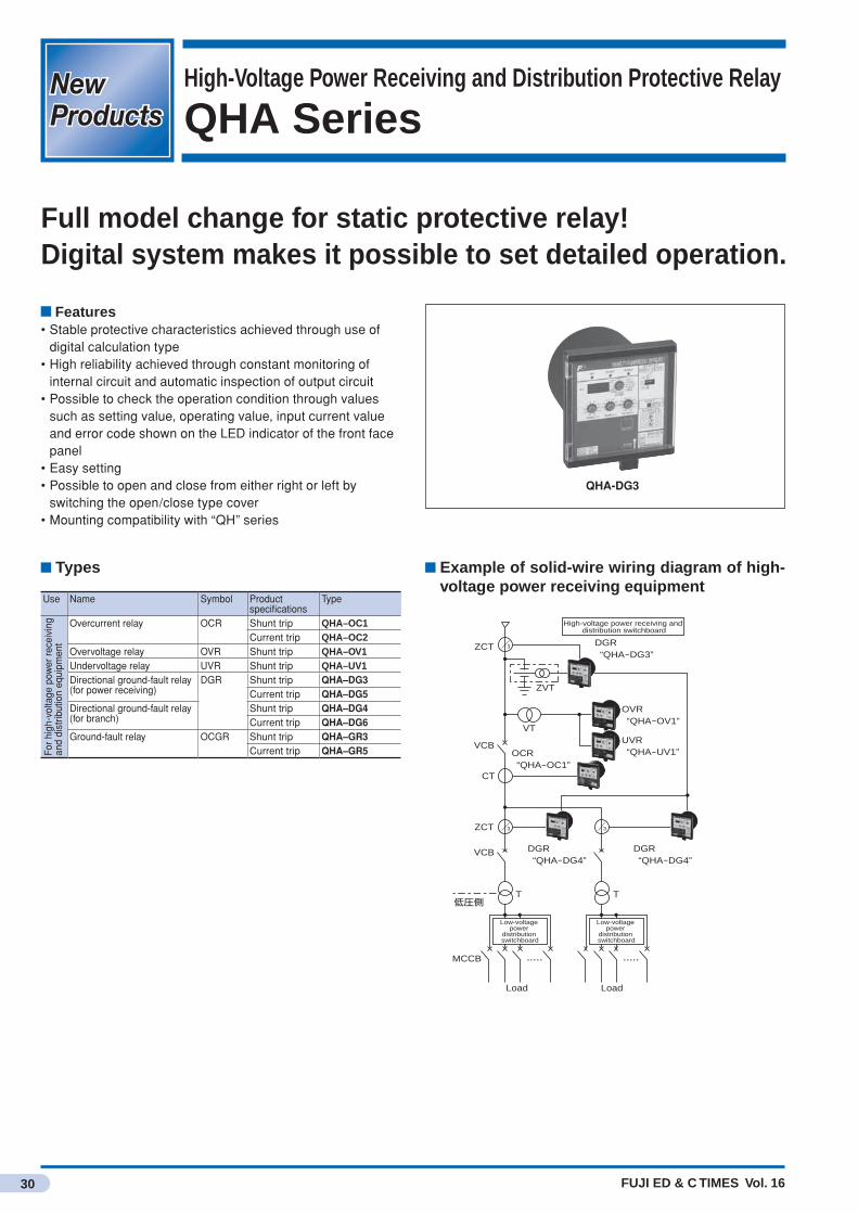
FUJI ED & C TIMES Vol. 16
New ProductsNew Products
30
High-Voltage Power Receiving and Distribution Protective Relay
QHA Series
Full model change for static protective relay!Digital system makes it possible to set detailed operation.
Types
Use Name Symbol Product specifications
Type
For h
igh-
volta
ge p
ower
rece
ivin
g an
d di
strib
utio
n eq
uipm
ent
Overcurrent relay OCR Shunt trip QHA–OC1Current trip QHA–OC2
Overvoltage relay OVR Shunt trip QHA–OV1Undervoltage relay UVR Shunt trip QHA–UV1Directional ground-fault relay (for power receiving)
DGR Shunt trip QHA–DG3Current trip QHA–DG5
Directional ground-fault relay (for branch)
Shunt trip QHA–DG4Current trip QHA–DG6
Ground-fault relay OCGR Shunt trip QHA–GR3Current trip QHA–GR5
QHA-DG3
Example of solid-wire wiring diagram of high-voltage power receiving equipment
High-voltage power receiving and distribution switchboard
Low-voltage power
distribution switchboard
Low-voltage power
distribution switchboard
ZCT
VCB
VCB
T
MCCB
ZCT
Load Load
CT
ZVT
VT
DGR“QHA-DG3”
OVR“QHA-OV1”
OCR“QHA-OC1”
DGR“QHA-DG4”
DGR“QHA-DG4”
低圧側
UVR“QHA-UV1”
3
3 3
T
Features• Stable protective characteristics achieved through use of
digital calculation type• High reliability achieved through constant monitoring of
internal circuit and automatic inspection of output circuit• Possible to check the operation condition through values
such as setting value, operating value, input current value and error code shown on the LED indicator of the front face panel
• Easy setting• Possible to open and close from either right or left by
switching the open/close type cover• Mounting compatibility with “QH” series
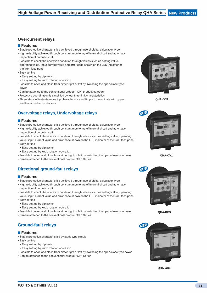
FUJI ED & C TIMES Vol. 16
New Products
31
High-Voltage Power Receiving and Distribution Protective Relay QHA Series
Features• Stable protective characteristics achieved through use of digital calculation type• High reliability achieved through constant monitoring of internal circuit and automatic
inspection of output circuit• Possible to check the operation condition through values such as setting value,
operating value, input current value and error code shown on the LED indicator of the front face panel
• Easy setting • Easy setting by dip switch • Easy setting by knob rotation operation• Possible to open and close from either right or left by switching the open/close type
cover• Can be attached to the conventional product “QH” product category• Protective coordination is simplified by four time-limit characteristics• Three steps of instantaneous trip characteristics → Simple to coordinate with upper
and lower protective devices
Overcurrent relays
QHA-OC1
Overvoltage relays, Undervoltage relays
Features• Stable protective characteristics achieved through use of digital calculation type• High reliability achieved through constant monitoring of internal circuit and automatic
inspection of output circuit• Possible to check the operation condition through values such as setting value, operating
value, input current value and error code shown on the LED indicator of the front face panel• Easy setting • Easy setting by dip switch • Easy setting by knob rotation operation• Possible to open and close from either right or left by switching the open/close type cover• Can be attached to the conventional product “QH” Series
Ground-fault relays
Features• Stable protective characteristics by static type circuit• Easy setting • Easy setting by dip switch • Easy setting by knob rotation operation• Possible to open and close from either right or left by switching the open/close type cover• Can be attached to the conventional product “QH” Series
Directional ground-fault relays
Features• Stable protective characteristics achieved through use of digital calculation type• High reliability achieved through constant monitoring of internal circuit and automatic
inspection of output circuit• Possible to check the operation condition through values such as setting value, operating
value, input current value and error code shown on the LED indicator of the front face panel• Easy setting • Easy setting by dip switch • Easy setting by knob rotation operation• Possible to open and close from either right or left by switching the open/close type cover• Can be attached to the conventional product “QH” Series
QHA-OV1
QHA-GR3
QHA-DG3

FUJI ED & C TIMES Vol. 16
New ProductsNew Products
32
Analog unit for transducer F-MPCWS3 Series
Possible to monitor energy by inputting an analog signal from devices such as a pressure gauge, flowmeter, thermometer and hygrometer.
Features• Analog input and communication output conversion unit for
Power Monitoring System F-MPC.• DC4 to 20 mA, 1 to 5 V DC, 0 to 10 V DC, etc. for analog
input. F-MPC-Net, Modbus for communication output• Supports two circuits of analog input. However, the two
circuits must have the same signal specifications.• All types of products conform to RoHS Directive.
SpecificationsType WS3MFInsulation type Photo coupler type
Standard accuracy ±0.2%Temperature characteristics 0.2%(% of span)
Inpu
t ci
rcui
t
Number of circuits Two circuits
Input signal Refer to the code described on the left
Input resistance Voltage input: Approx. 1 MΩ Current input: Approx. 100Ω
Ext
erna
l pow
er
supp
ly Range of power source and consumption VA
AC80 to 264V (AC110V: 3.5VA, AC220V: 5.0VA)DC80 to 264V (DC110V/220V: 3.0W)
Inrush current (time constant)
Rated voltage 110 V AC 1.7 A or less (approx. 1.0 ms)220 V AC 3.3 A or less (approx. 1.0 ms)110 V DC 1.2 A or less (approx. 1.0 ms)220 V DC 2.4 A or less (approx. 1.0 ms)
Com
mun
icat
ion
outp
ut Standard EIA RS-485Transmission method Half-duplex two-line type
Synchronization system Start-stop synchronization type
Protocol F-MPC-Net or Modbus
Transmission speed 19200bpsTransmission code NRZStart bit 1 bit
Data length F-MPC-Net: 7 bits, Modbus: 8 bits
Parity Odd number
BCC(CRC)F-MPC-Net:Even number horizontal parityModbus:CRC-16
Stop bit 1 bit
Address 1 to 99 (changeable by switch setting)
Transmission characters ASCII code
Transmission distance 1,000 m (total length)
Number of connection units
Maximum 64 units/system (including other devices)
Terminating resistorTerminating resistor (100Ω) is connected to the transmission line by a short circuit of the DXB terminal and Ter. Terminal.
Insulation resistance 50 MΩ or more (500 V DC)
Dielectric strengthInput, output, power source, to groundBetween inputs
2000 V AC 1 min.
Range of service temperature and humidity
-10 to +55ºC, 90%RH or less (no dew condensation shall be observed)
Storage temperature -20 to +70℃Mass Approx. 180 g (supplied with socket WS212 type)
Type number nomenclatureWS3MF-□□Y□Y□Y1
Design order
External power supply
0 AC・DC80~ 264V
Output signal
F F-MPC-NetCommunicat ion output (RS-485)
M ModbusCommunication output(RS-485)
(Note)Thesocket(WS212)isastandardaccessory.
Input signal
23 DC0~ 50mV 42 DC±5V33 DC0~ 60mV 24 DC±10V11 DC0~100mV 27 DC0~ 1mA12 DC0~ 1V 54 DC0~ 5mA13 DC0~ 5V 55 DC0~ 10mA14 DC0~ 10V 56 DC0~ 16mA15 DC1~ 5V 16 DC4~ 20mA50 DC±50mV 57 DC±1mA51 DC±60mV 58 DC±5mA52 DC±100mV 59 DC±10mA53 DC±1V
Block chart
Input 1
Insulationpowersourcecircuit
Inputfilter
Photocoupler
insulation
Photocoupler
insulation
Photocoupler
insulation
CPU
Addresssettingrotaryswitch
Resetswitch
RS-485communi-
cationcircuit
Outgoingcircuit
Outgoingcircuit
Pulsewidth
modulationcircuit
Pulsewidth
modulationcircuit
Inputfilter
Input 2
Externalpowersupply
RS-485
WS3MF
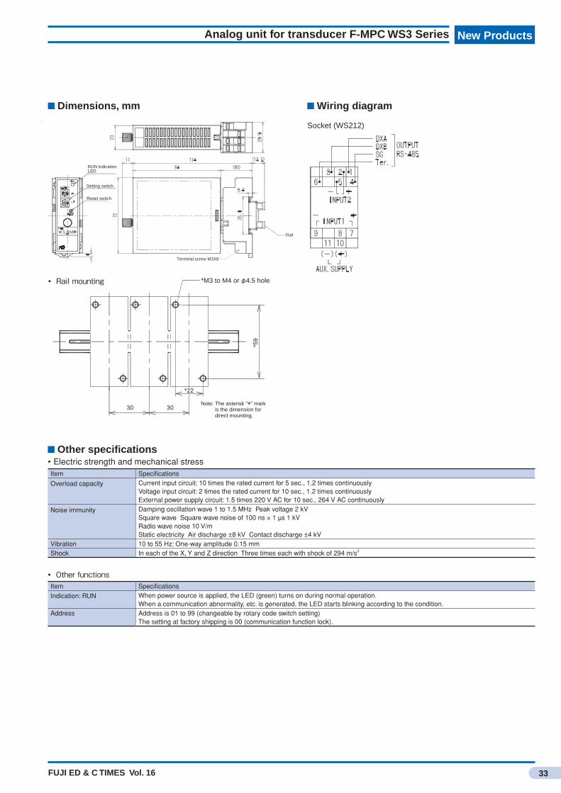
FUJI ED & C TIMES Vol. 16
New Products
33
Analog unit for transducer F-MPC WS3 Series
Dimensions, mm Wiring diagram
Other specifications• Electric strength and mechanical stressItem Specifications
Overload capacity Current input circuit: 10 times the rated current for 5 sec., 1.2 times continuouslyVoltage input circuit: 2 times the rated current for 10 sec., 1.2 times continuouslyExternal power supply circuit: 1.5 times 220 V AC for 10 sec., 264 V AC continuously
Noise immunity Damping oscillation wave 1 to 1.5 MHz Peak voltage 2 kVSquare wave Square wave noise of 100 ns × 1 μs 1 kVRadio wave noise 10 V/mStatic electricity Air discharge ±8 kV Contact discharge ±4 kV
Vibration 10 to 55 Hz: One-way amplitude 0.15 mmShock In each of the X, Y and Z direction Three times each with shock of 294 m/s2
• OtherfunctionsItem Specifications
Indication: RUN When power source is applied, the LED (green) turns on during normal operation.When a communication abnormality, etc. is generated, the LED starts blinking according to the condition.
Address Address is 01 to 99 (changeable by rotary code switch setting)The setting at factory shipping is 00 (communication function lock).
Rail
RUN indicationLED
Setting switch
Reset switch
Terminal screw M3X8
Socket (WS212)
Note: The asterisk “*” markis the dimension for direct mounting.
30 30
*59
*22
*M3 to M4 or φ4.5 hole• Railmounting
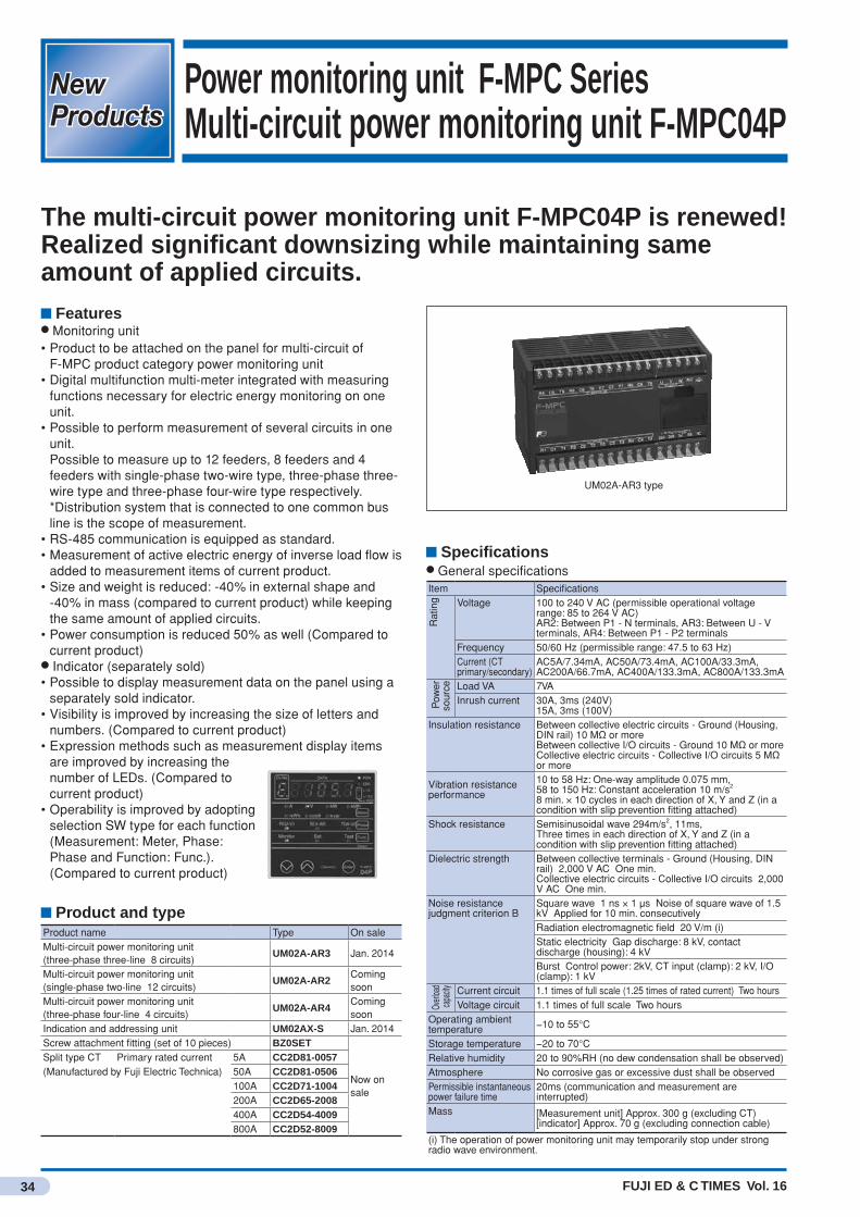
FUJI ED & C TIMES Vol. 16
New ProductsNew Products
34
Power monitoring unit F-MPC SeriesMulti-circuit power monitoring unit F-MPC04P
The multi-circuit power monitoring unit F-MPC04P is renewed!Realized significant downsizing while maintaining same amount of applied circuits.
Features● Monitoring unit• Product to be attached on the panel for multi-circuit of
F-MPC product category power monitoring unit • Digital multifunction multi-meter integrated with measuring
functions necessary for electric energy monitoring on one unit.
• Possible to perform measurement of several circuits in one unit.
Possible to measure up to 12 feeders, 8 feeders and 4 feeders with single-phase two-wire type, three-phase three-wire type and three-phase four-wire type respectively.
*Distribution system that is connected to one common bus line is the scope of measurement.
• RS-485 communication is equipped as standard.• Measurement of active electric energy of inverse load flow is
added to measurement items of current product.• Size and weight is reduced: -40% in external shape and
-40% in mass (compared to current product) while keeping the same amount of applied circuits.
• Power consumption is reduced 50% as well (Compared to current product)
● Indicator (separately sold)• Possible to display measurement data on the panel using a
separately sold indicator.• Visibility is improved by increasing the size of letters and
numbers. (Compared to current product)• Expression methods such as measurement display items
are improved by increasing the number of LEDs. (Compared to current product)
• Operability is improved by adopting selection SW type for each function (Measurement: Meter, Phase: Phase and Function: Func.). (Compared to current product)
UM02A-AR3 type
Product name Type On saleMulti-circuit power monitoring unit (three-phase three-line 8 circuits)
UM02A-AR3 Jan. 2014
Multi-circuit power monitoring unit (single-phase two-line 12 circuits)
UM02A-AR2Coming soon
Multi-circuit power monitoring unit (three-phase four-line 4 circuits)
UM02A-AR4Coming soon
Indication and addressing unit UM02AX-S Jan. 2014Screw attachment fitting (set of 10 pieces) BZ0SET
Now on sale
Split type CT Primary rated current 5A CC2D81-0057(Manufactured by Fuji Electric Technica) 50A CC2D81-0506
100A CC2D71-1004200A CC2D65-2008400A CC2D54-4009800A CC2D52-8009
Product and type
Specifications● General specificationsItem Specifications
Rat
ing Voltage 100 to 240 V AC (permissible operational voltage
range: 85 to 264 V AC)AR2: Between P1 - N terminals, AR3: Between U - V terminals, AR4: Between P1 - P2 terminals
Frequency 50/60 Hz (permissible range: 47.5 to 63 Hz)Current (CT primary/secondary)
AC5A/7.34mA, AC50A/73.4mA, AC100A/33.3mA, AC200A/66.7mA, AC400A/133.3mA, AC800A/133.3mA
Pow
er
sour
ce Load VA 7VAInrush current 30A, 3ms (240V)
15A, 3ms (100V)Insulation resistance Between collective electric circuits - Ground (Housing,
DIN rail) 10 MΩ or moreBetween collective I/O circuits - Ground 10 MΩ or moreCollective electric circuits - Collective I/O circuits 5 MΩ or more
Vibration resistance performance
10 to 58 Hz: One-way amplitude 0.075 mm,58 to 150 Hz: Constant acceleration 10 m/s2
8 min. × 10 cycles in each direction of X, Y and Z (in a condition with slip prevention fitting attached)
Shock resistance Semisinusoidal wave 294m/s2, 11ms, Three times in each direction of X, Y and Z (in a condition with slip prevention fitting attached)
Dielectric strength Between collective terminals - Ground (Housing, DIN rail) 2,000 V AC One min.Collective electric circuits - Collective I/O circuits 2,000 V AC One min.
Noise resistance judgment criterion B
Square wave 1 ns × 1 μs Noise of square wave of 1.5 kV Applied for 10 min. consecutivelyRadiation electromagnetic field 20 V/m (i)Static electricity Gap discharge: 8 kV, contact discharge (housing): 4 kVBurst Control power: 2kV, CT input (clamp): 2 kV, I/O (clamp): 1 kV
Overl
oad
capa
city Current circuit 1.1 times of full scale (1.25 times of rated current) Two hours
Voltage circuit 1.1 times of full scale Two hoursOperating ambient temperature −10 to 55°C
Storage temperature −20 to 70°CRelative humidity 20 to 90%RH (no dew condensation shall be observed)Atmosphere No corrosive gas or excessive dust shall be observedPermissible instantaneous power failure time
20ms (communication and measurement are interrupted)
Mass [Measurement unit] Approx. 300 g (excluding CT)[indicator] Approx. 70 g (excluding connection cable)
(i) The operation of power monitoring unit may temporarily stop under strong radio wave environment.
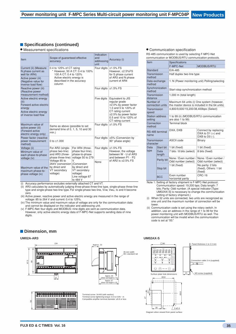
FUJI ED & C TIMES Vol. 16
New Products
35
Power monitoring unit F-MPC Series Multi-circuit power monitoring unit F-MPC04P
Specifications (continued)● Measurement specifications
Item Scope of guaranteed effective accuracy
Indication and addressing unit
Accuracy (i)
Current (ii) (Measure N phase current as well for AR4)
0.4 to 125% of CT rating * However, 50 A CT: 0.4 to 100% 100 A CT: 0.4 to 120% Active electric energy is
described in the accuracy column
Four digits ±1.5% FSHowever, ±2.5%FS for S phase current of AR3 and N phase current of AR4
Active power (iii) (Negative value for inverse load flow)Reactive power (iii) (Reactive power measurement method)
Four digits ±1.5% FS
Active electric energy (iii)Forward active electric energy
Five digits Equivalent to JIS regular grade±2.0% by power factor 1.0 and 5 to 120% of CT rating current±2.5% by power factor 0.5 and 10 to 120% of CT rating current
Active electric energy of inverse load flow
Maximum value of active power (iii)(Forward active electric energy only)
Same as above (possible to set demand time of 0, 1, 5, 10 and 30 min.)
Four digits ±1.5% FS
Power factor (reactive power measurement method)
0 to ±1.000Four digits ±5% (Conversion by
90° phase angle)
Voltage (ii) For AR2 (single-phase two-line) and AR3 (three-phase three-line)Voltage 85 to 264V (conversion by direct and VT secondary voltage)
For AR4 (three-phase four-line), phase-to-phase voltage 50 to 279 V(Conversion by direct and VT secondary voltage)Line voltage 87 to 484 V
Four digits ±1.5% FSHowever, the voltage between W - U of AR3 and between P1 - P2 of AR2 is ±2.5% FS
Minimum value of each phase-to-phase voltage (iv)
Maximum value of the maximum phase-to-phase voltage (iv)
None
(i) Accuracy performance excludes externally attached CT and VT.(ii) AR3 calculates by automatically judging three-phase three-line type, single-phase three-line
type and single-phase two-line type. For single-phase two-line, Vvw, Vwu, Is and It become zero.
(iii) Active power, reactive power and active electric energy are measured in the range of voltage: 85 to 264 V and current: 0.4 to 125%.
(iv) The minimum value and maximum value of voltage are only for the communication data and cannot be displayed on the indicator and addressing unit.
(v) F-MPC-Net: four digits and MODBUS: nine digits are sent as communication data. However, only active electric energy data of F-MPC-Net supports sending data of nine digits.
● Communication specificationRS-485 communication is used by selecting F-MPC-Net communication or MODBUS/RTU communication protocols.
Item SpecificationsF-MPC-Net MODBUS/RTU
Standard EIA-485Transmission method
Half duplex two-line type
Data exchange method
1: N (Power monitoring unit) Polling/selecting
Synchronization method Start-stop synchronization method
Transmission distance
1,000 m (total length)
Number of connection units
Maximum 64 units (i) One system (however, the master device is included in the 64 units)
Transmission speed
4,800/9,600/19,200/38,400bps (Select)
Station address setting
1 to 99 (ii) (MODBUS/RTU communication are also 1 to 99)
Connection method
Terminal block
RS-485 terminal name
DXA, DXB Connect by replacing DXA to D1 (+) and DXB to D0 (-).
Transmission character
ASCII code Binary
Data type
Start bit 1 bit (fixed) 1 bit (fixed)Data length
7 bits / 8 bits (select) 8 bits (fixed)
Parity bit None / Even number / Odd number (select)
None / Even number / Odd number (select)
Stop bit1 bit (fixed) No parity: 2 bits
(fixed), Others: 1 bit (fixed)
BCC Even number horizontal parity
CRC-16
Note 1: Setting of factory shipment is F-MPC-Net protocol; Communication speed: 19,200 bps; Data length: 7 bits; Parity: Odd number. (A special indicator [Type: UM02AX-S] is necessary to change the communication setting of factory shipment.)
(i) When 32 units are connected, two units are recognized as one unit and the maximum number of connection will be lower.
(ii) Communication code is set using the rotary switch. In addition, use an address in the range of 1 to 99 for the power monitoring unit with MODBUS/RTU as well. The communication will be invalid when the communication code is set at “00.”
UM02A-AR3 UM02AX-S
Diagram when viewed from panel surface
■ 80
Surface plate hole dimensions
Connection cable 3 m (supplied)
730
47
10
69.8
2-ø3.4
21
69.8
M3 screw (supplied)
Panel thickness 1 to 2.3 mm
80
87.5
56
134
Terminal screw: 34-M3 (with washer)Terminal screw tightening torque: 0.5 to 0.6N・mCompatible amplifier terminal diameter: ø5.8 or less
35 mm widthIEC standard rail
Approx. 23
Approx. 60 (when rail height is 7.5)
Approx. 67 (when rail height is 15)
12
Fuj
i Ele
ctric
FA
Dimension, mm

FUJI ED & C TIMES Vol. 16
New ProductsNew Products
36
AC power regulator [APR]APR-D Series (three-phase)
Three-phase APR-D Series is the successor of APR-L. Space-saving, wire-saving and low-cost type of APR with a significant improvement in function and performance achieved by installing a CPU.
Features• Thyristor pure inverse-parallel type (six arms).• The output range is 0–100% of the main circuit power source
voltage. However, the amount of voltage decrease due to thyristor
specific resistance is excluded• Possible to switch between the waveform control types
(phase control, cycle control or phase angle proportion control).
Phase control type (0–100%)Output voltage
93%Vα=30°
Ignition phase angle α
21%Vα=120°
71%V(1/2)
45%V(1/5)
0.5–2 sec.(Changeable by inverter time)
Cycle control type (continuous type)
Output voltage
• With main circuit terminal block cover.• Mounting pitch is the same as APR-L. However, 400 V system 45/60 A product is excluded• Output is RMS value linear characteristic for various
settings.• Digital settings such as base load setting and gradient
setting as well as a monitor function is provided as standard.
Monitor mode 2b. 01 m_vr
Aod
Function code
(↓ 1 sec.) or no control20 sec.
Automatic feeding of data by long pressing of one second or more
or
Setting mode
Function code data
Operation example
Suppliedwith100Acommunicationboard
45/60Astandard
20Astandard
• Soft start, soft up and soft down time can be set individually from 0 to 100.0 sec.
• Soft start functions securely upon inrush of main circuit power source.
• The range of power source voltage is 200–240 V AC and 380–480 V AC.
(Note) Operating transformer is supplied to 380–440 V AC product.
Operating transformer of 380–480 V AC product is sold separately.
• Communication control is possible as an option. Main unit option type: ZAP: Possible to perform parallel operation with a
maximum of 50 units. Flicker prevention function is available during cycle control.
ZAM: Various settings and types of monitoring by RS485 (Modbus RTU) are available.
• All products conform to CE marking
Rating, type and product codeNumber of phases Input voltage Output current [A] TypeThree-phase 200−240V 20 RPDW2020-T
45 RPDW2045-T60 RPDW2060-T100 RPDW2100-T
380−440V 20 RPDW4020-T45 RPDW4045-T60 RPDW4060-T100 RPDW4100-T
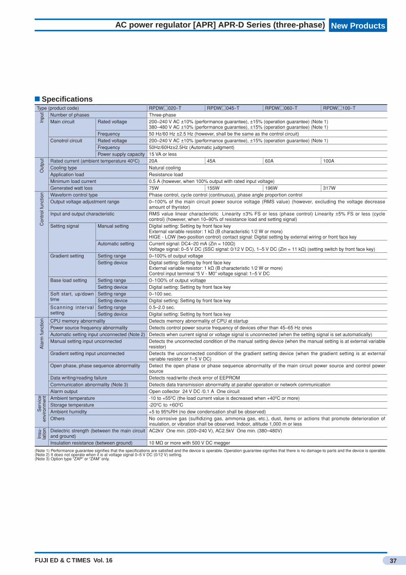
FUJI ED & C TIMES Vol. 16
New Products
37
AC power regulator [APR] APR-D Series (three-phase)
SpecificationsType (product code) RPDW□020-T RPDW□045-T RPDW□060-T RPDW□100-T
Inpu
t
Number of phases Three-phaseMain circuit Rated voltage 200–240 V AC ±10% (performance guarantee), ±15% (operation guarantee) (Note 1)
380–480 V AC ±10% (performance guarantee), ±15% (operation guarantee) (Note 1)Frequency 50 Hz/60 Hz ±2.5 Hz (however, shall be the same as the control circuit)
Conotrol circuit Rated voltage 200–240 V AC ±10% (performance guarantee), ±15% (operation guarantee) (Note 1)Frequency 50Hz/60Hz±2.5Hz (Automatic judgment)Power supply capacity 15 VA or less
Out
put
Rated current (ambient temperature 40ºC) 20A 45A 60A 100ACooling type Natural coolingApplication load Resistance loadMinimum load current 0.5 A (however, when 100% output with rated input voltage)Generated watt loss 75W 155W 196W 317W
Con
trol
func
tion Waveform control type Phase control, cycle control (continuous), phase angle proportion control
Output voltage adjustment range 0–100% of the main circuit power source voltage (RMS value) (however, excluding the voltage decrease amount of thyristor)
Input and output characteristic RMS value linear characteristic Linearity ±3% FS or less (phase control) Linearity ±5% FS or less (cycle control) (however, when 10–90% of resistance load and setting signal)
Setting signal Manual setting Digital setting: Setting by front face keyExternal variable resistor: 1 kΩ (B characteristic 1/2 W or more)HIGE - LOW (two-position control) contact signal: Digital setting by external wiring or front face key
Automatic setting Current signal: DC4–20 mA (Zin = 100Ω)Voltage signal: 0–5 V DC (SSC signal: 0/12 V DC), 1–5 V DC (Zin = 11 kΩ) (setting switch by front face key)
Gradient setting Setting range 0–100% of output voltageSetting device Digital setting: Setting by front face key
External variable resistor: 1 kΩ (B characteristic 1/2 W or more)Control input terminal “5 V - M0” voltage signal: 1–5 V DC
Base load setting Setting range 0–100%ofoutputvoltageSetting device Digital setting: Setting by front face key
Soft start, up/down time
Setting range 0–100 sec.Setting device Digital setting: Setting by front face key
Scanning interval setting
Setting range 0.5–2.0 sec.Setting device Digital setting: Setting by front face key
Ala
rm fu
nctio
n CPU memory abnormality Detects memory abnormality of CPU at startupPower source frequency abnormality Detects control power source frequency of devices other than 45–65 Hz onesAutomatic setting input unconnected (Note 2) Detects when current signal or voltage signal is unconnected (when the setting signal is set automatically)Manual setting input unconnected Detects the unconnected condition of the manual setting device (when the manual setting is at external variable
resistor)Gradient setting input unconnected Detects the unconnected condition of the gradient setting device (when the gradient setting is at external
variable resistor or 1–5 V DC)Open phase, phase sequence abnormality Detect the open phase or phase sequence abnormality of the main circuit power source and control power
sourceData writing/reading failure Detects read/write check error of EEPROMCommunication abnormality (Note 3) Detects data transmission abnormality at parallel operation or network communicationAlarm output Open collector 24 V DC /0.1 A One circuit
Ser
vice
en
viro
nmen
t
Ambient temperature -10 to +55ºC (the load current value is decreased when +40ºC or more)Storage temperature -20ºCto+60ºCAmbient humidity +5 to 95%RH (no dew condensation shall be observed)Others No corrosive gas (sulfidizing gas, ammonia gas, etc.), dust, items or actions that promote deterioration of
insulation, or vibration shall be observed. Indoor, altitude 1,000 m or less
Insu
-la
tion Dielectric strength (between the main circuit
and ground)AC2kV One min. (200–240 V), AC2.5kV One min. (380–480V)
Insulation resistance (between ground) 10 MΩ or more with 500 V DC megger
(Note 1) Performance guarantee signifies that the specifications are satisfied and the device is operable. Operation guarantee signifies that there is no damage to parts and the device is operable.(Note 2) It does not operate when it is at voltage signal 0–5 V DC (0/12 V) setting.(Note 3) Option type “ZAP” or “ZAM” only.
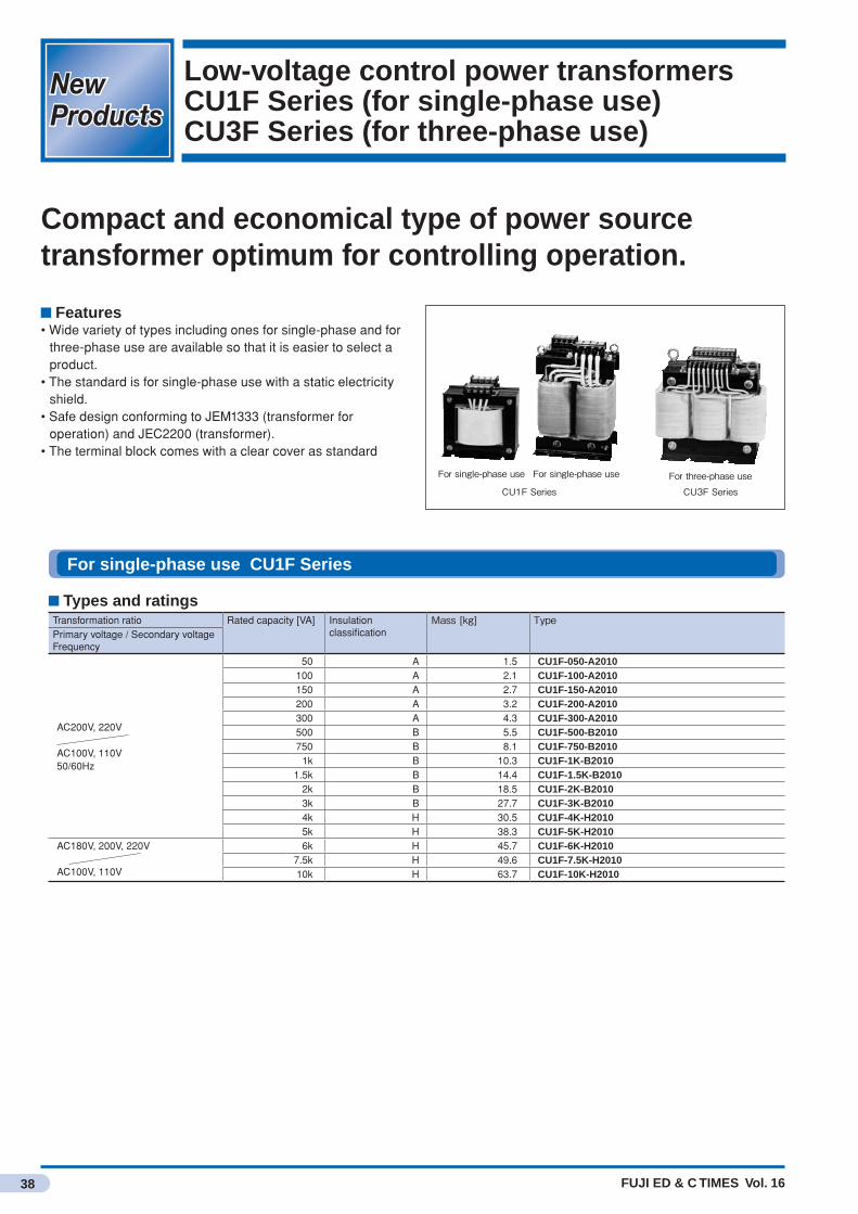
FUJI ED & C TIMES Vol. 16
New ProductsNew Products
38
Low-voltage control power transformersCU1F Series (for single-phase use) CU3F Series (for three-phase use)
Compact and economical type of power source transformer optimum for controlling operation.
Features• Wide variety of types including ones for single-phase and for
three-phase use are available so that it is easier to select a product.
• The standard is for single-phase use with a static electricity shield.
• Safe design conforming to JEM1333 (transformer for operation) and JEC2200 (transformer).
• The terminal block comes with a clear cover as standard
CU3FSeries
Forsingle-phaseuse
CU1FSeries
Forsingle-phaseuse Forthree-phaseuse
For single-phase use CU1F Series
Types and ratingsTransformation ratio Rated capacity [VA] Insulation
classificationMass[kg] Type
Primary voltage / Secondary voltageFrequency
AC200V, 220V
AC100V, 110V50/60Hz
50 A 1.5 CU1F-050-A2010100 A 2.1 CU1F-100-A2010150 A 2.7 CU1F-150-A2010200 A 3.2 CU1F-200-A2010300 A 4.3 CU1F-300-A2010500 B 5.5 CU1F-500-B2010750 B 8.1 CU1F-750-B2010
1k B 10.3 CU1F-1K-B20101.5k B 14.4 CU1F-1.5K-B2010
2k B 18.5 CU1F-2K-B20103k B 27.7 CU1F-3K-B20104k H 30.5 CU1F-4K-H20105k H 38.3 CU1F-5K-H2010
AC180V, 200V, 220V
AC100V, 110V
6k H 45.7 CU1F-6K-H20107.5k H 49.6 CU1F-7.5K-H201010k H 63.7 CU1F-10K-H2010
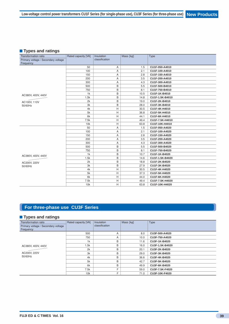
FUJI ED & C TIMES Vol. 16
New Products
39
Low-voltage control power transformers CU1F Series (for single-phase use), CU3F Series (for three-phase use)
For three-phase use CU3F Series
Types and ratingsTransformation ratio Rated capacity [VA] Insulation
classificationMass[kg] Type
Primary voltage / Secondary voltageFrequency
AC380V, 400V, 440V
AC200V, 220V50/60Hz
500 A 8.0 CU3F-500-A4020750 A 10.0 CU3F-750-A4020
1k B 11.6 CU3F-1K-B40201.5k B 16.0 CU3F-1.5K-B4020
2k B 20.1 CU3F-2K-B40203k B 29.0 CU3F-3K-B40204k B 36.6 CU3F-4K-B40205k B 42.7 CU3F-5K-B40206k B 49.9 CU3F-6K-B4020
7.5k F 59.0 CU3F-7.5K-F402010k F 71.0 CU3F-10K-F4020
Types and ratingsTransformation ratio Rated capacity [VA] Insulation
classificationMass[kg] Type
Primary voltage / Secondary voltageFrequency
AC380V, 400V, 440V
AC100V, 110V50/60Hz
50 A 1.5 CU1F-050-A4010100 A 2.1 CU1F-100-A4010150 A 2.8 CU1F-150-A4010200 A 3.5 CU1F-200-A4010300 A 4.3 CU1F-300-A4010500 B 5.5 CU1F-500-B4010750 B 8.1 CU1F-750-B4010
1k B 10.5 CU1F-1K-B40101.5k B 14.8 CU1F-1.5K-B4010
2k B 19.0 CU1F-2K-B40103k B 28.0 CU1F-3K-B40104k H 30.5 CU1F-4K-H40105k H 36.8 CU1F-5K-H40106k H 44.1 CU1F-6K-H4010
7.5k H 49.4 CU1F-7.5K-H401010k H 63.8 CU1F-10K-H4010
AC380V, 400V, 440V
AC200V, 220V50/60Hz
50 A 1.5 CU1F-050-A4020100 A 2.1 CU1F-100-A4020150 A 2.8 CU1F-150-A4020200 A 3.5 CU1F-200-A4020300 A 4.3 CU1F-300-A4020500 B 5.5 CU1F-500-B4020750 B 8.1 CU1F-750-B4020
1k B 10.7 CU1F-1K-B40201.5k B 14.6 CU1F-1.5K-B4020
2k B 18.8 CU1F-2K-B40203k B 27.9 CU1F-3K-B40204k H 30.5 CU1F-4K-H40205k H 37.3 CU1F-5K-H40206k H 44.0 CU1F-6K-H4020
7.5k H 49.4 CU1F-7.5K-H402010k H 63.8 CU1F-10K-H4020
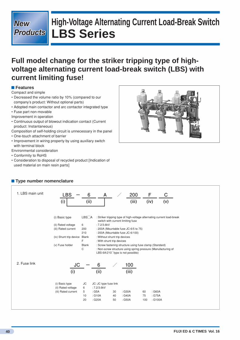
FUJI ED & C TIMES Vol. 16
New ProductsNew Products
40
High-Voltage Alternating Current Load-Break SwitchLBS Series
Full model change for the striker tripping type of high-voltage alternating current load-break switch (LBS) with current limiting fuse!
FeaturesCompact and simple• Decreased the volume ratio by 10% (compared to our
company’s product: Without optional parts)• Adopted main contactor and arc contactor integrated type• Fuse part non-movableImprovement in operation• Continuous output of blowout indication contact (Current
product: Instantaneous)Composition of self-holding circuit is unnecessary in the panel• One-touch attachment of barrier• Improvement in wiring property by using auxiliary switch
with terminal blockEnvironmental consideration• Conformity to RoHS• Consideration to disposal of recycled product [Indication of
used material on main resin parts]
Type number nomenclature
JC − 6 / 100(i) (ii) (iii)
(i) Basic type LBS□A : Striker tripping type of high-voltage alternating current load-break switch with current limiting fuse
(ii) Rated voltage 6 : 7.2/3.6kV(iii) Rated current 200 : 200A (Mountable fuse JC-6/5 to 75)
210 : 200A (Mountable fuse JC-6/100)
(iv) Shunt trip device Blank : Without shunt trip devicesF : With shunt trip devices
(v) Fuse holder Blank : Screw fastening structure using fuse clamp (Standard)C : Non-screw structure using spring pressure (Manufacturing of
LBS-6A/210■type is not possible)
(i) Basic type JC JC: JC type fuse link(ii) Rated voltage 6 : 7.2/3.6kV(iii) Rated current 5 : G5A 30 : G30A 60 : G60A
10 : G10A 40 : G40A 75 : G75A
20 : G20A 50 : G50A 100 : G100A
LBS − 6 A / 200 F C(i) (ii) (iii) (iv) (v)
2. Fuse link
1. LBS main unit
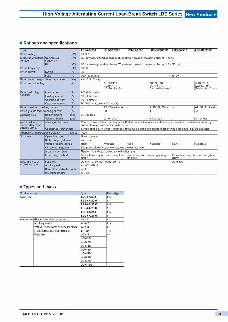
FUJI ED & C TIMES Vol. 16
New Products
41
High-Voltage Alternating Current Load-Break Switch LBS Series
Ratings and specifications
Types and mass
Type LBS-6A/200 LBS-6A/200F LBS-6A/200C LBS-6A/200FC LBS-6A/210 LBS-6A/210FRated voltage (kV) 7.2/3.6Dielectric withstand voltage
Commercial frequency
(kV) 22 (between ground or phase), 35 (between poles of the same phase) [1 min.]
BIL (kV) 60 (between ground or phase), 70 (between poles of the same phase) [1.2 × 50 μs]Rated frequency (Hz) 50/60Rated current Switch (A) 200
Fuse (A) Maximum: G75 G100Rated cable charging breaking current (kA) A12.5 (A: Once)Rated control voltage (V) − AC100/110
DC100/110(3A short time 5 sec.)
− AC100/110DC100/110(3A short time 5 sec.)
− AC100/110DC100/110(3A short time 5 sec.)
Rated switching capacity
Load current (A) 200 (200 times)Exciting current (A) 10 (10 times)Charging current (A) 10 (10 times)Capacitor current (A) 50 (200 times, with 6% reactor)
Rated overload breaking current (A) − A1100 (A: Once) − A1100 (A: Once) − A1100 (A: Once)Rated ground fault breaking current (A) − 30 − 30 − 30Opening time Striker tripping (sec) 0.13 or less
Voltage tripping (sec) − 0.1 or less − 0.1 or less − 0.1 or lessAdditional function achieved by striker tripping device
All-range shutdown Can shutdown all fault currents from 40kA or less of the fuse rated breaking current to fuse minimum breaking current through combination with a fuse
Open phase prevention Switch opens even when one phase of the fuse breaks and disconnects between the power source and loadMechanical make/break durability (times) 1000Structure Operation type Hook operation
Striker tripping device AvailableVoltage tripping device None Available None Available None AvailableContact arrangement Integrated electrification contact and arc contact typeArc extinction type Narrow slit and gas cooling arc extinction typeFuse fixing method Screw fastening structure using fuse
clampNon-screw structure using spring pressure
Screw fastening structure using fuse clamp
Separately sold accessory type
Fuse link JC-6/5, 10, 20, 30, 40, 50, 60, 75 JC-6/100Auxiliary switch AUX-7, AUX-8Blown-fuse indicator contact AL-3CInsulation barrier SP-4D
Product name Type Mass (kg)Mainunit LBS-6A/200 8.5
LBS-6A/200F 9LBS-6A/200C 8.5LBS-6A/200FC 9LBS-6A/210 8.5LBS-6A/210F 9
Accessory Blown-fuseindicatorcontact AL-3C 0.3Auxiliary switch AUX-7 0.5With auxiliary contact terminal block AUX-8 0.7Insulation barrier (four pieces) SP-4D 1.3Fuse link JC-6/5 0.6
JC-6/10JC-6/20JC-6/30JC-6/40JC-6/50JC-6/60JC-6/75JC-6/100 1.1
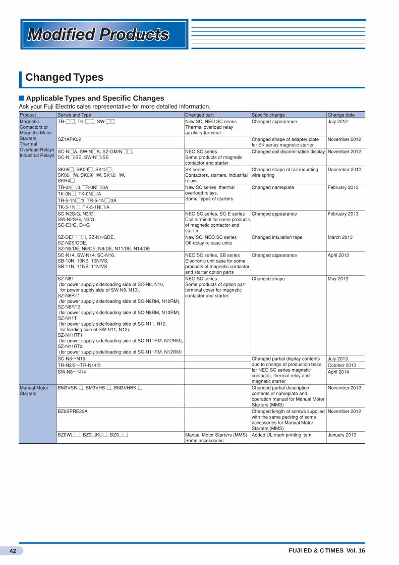
FUJI ED & C TIMES Vol. 16
Modified ProductsModified Products
42
Changed Types
Applicable Types and Specific ChangesAsk your Fuji Electric sales representative for more detailed information.Product Series and Type Changed part Specific change Change dateMagnetic Contactors or Magnetic Motor Starters Thermal Overload Relays Industrial Relays
TR-□□, TK-□□, SW-□□ New SC, NEO SC series Thermal overload relay auxiliary terminal
Changed appearance July 2012
SZ1APK02 Changed shape of adapter plate for SK series magnetic starter
November 2012
SC-N□A, SW-N□A, SZ-GM/N□□, SC-N□/SE, SW-N□/SE
NEO SC series Some products of magnetic contactor and starter
Changed coil discrimination display November 2012
SK06□, SK09□, SK12□, SK06□W, SK09□W, SK12□W, SKH4□
SK series Contactors, starters, industrial relays
Changed shape of rail mounting wire spring
December 2012
TR-0N□/3, TR-0N□/3A New SC series thermal overload relays, Some Types of starters
Changed nameplate February 2013TK-0N□, TK-0N□/ATR-5-1N□/3, TR-5-1N□/3ATK-5-1N□, TK-5-1N□/ASC-N2S/G, N3/G, SW-N2S/G, N3/G, SC-E3/G, E4/G
NEO SC series, SC-E series Coil terminal for some products of magnetic contactor and starter
Changed appearance February 2013
SZ-DE□□□, SZ-N1/GDE, SZ-N2S/GDE, SZ-N5/DE, N6/DE, N8/DE, N11/DE, N14/DE
New SC, NEO SC series Off-delay release units
Changed insulation tape March 2013
SC-N14, SW-N14, SC-N16, SB-10N, 10NB, 10N/VS, SB-11N, 11NB, 11N/VS
NEO SC series, SB series Electronic unit case for some products of magnetic contactor and starter option parts
Changed appearance April 2013
SZ-N8T (for power supply side/loading side of SC-N8, N10, for power supply side of SW-N8, N10), SZ-N8RT1 (for power supply side/loading side of SC-N8RM, N10RM), SZ-N8RT2 (for power supply side/loading side of SC-N8RM, N10RM), SZ-N11T (for power supply side/loading side of SC-N11, N12, for loading side of SW-N11, N12), SZ-N11RT1 (for power supply side/loading side of SC-N11RM, N12RM), SZ-N11RT2 (for power supply side/loading side of SC-N11RM, N12RM)
NEO SC series Some products of option part terminal cover for magnetic contactor and starter
Changed shape May 2013
SC-N8~N16 Changed partial display contents due to change of production base for NEO SC series magnetic contactor, thermal relay and magnetic starter
July 2013TR-N2/3~TR-N14/3 October 2013SW-N8~N14 April 2014
Manual Motor Starters
BM3VSB-□, BM3VHB-□, BM3VHBK-□ Changed partial description contents of nameplate and operation manual for Manual Motor Starters (MMS)
November 2012
BZ0BPRE22A Changed length of screws supplied with the same packing of some accessories for Manual Motor Starters (MMS)
November 2012
BZ0W□□, BZ0□KU□, BZ0□□ Manual Motor Starters (MMS) Some accessories
Added UL mark printing item January 2013

43FUJI ED & C TIMES Vol. 16
Modified Products
Product Series and Type Changed part Specific change Change dateMolded Case Circuit Breakers Earth Leakage Circuit Breakers
BW32□□□, BW50□□□, BW63□□□, BW100□□□, EW32□□□, EW50□□□, EW63□□□, EW100□□□
G-TWIN series Cases of auto breaker and earth leakage circuit breaker (back surface)
Changed shape February 2013
BW9UVHA-3, BW9UVJA-3 Changed dust-proof type iron box for MCCB and ELCB G-TWIN series 400AF to 800AF
April 2013
BW400EAG-2P, BW400SAG-2P, BW400RAG-2P, BW400HAG-2P, BW400EAA-2P, BW400SAA-2P, BW400RAA-2P, BW400HAA-2P, BW400RAQ-2P, BW400HAQ-2P, BW400EAT-2P, BW400RAT-2P, BW400RAB-2P, BW400HAB-2P, BW400EAS-2P, BW400RAS-2P, BW400EAGU-2P, BW400SAGU-2P, BW400RAGU-2P, BW400HAGU-2P
Changed insulation board on loading side of MCCB G-TWIN series 400AF
June 2013
BW250EAG-2P, BW250EAG-3P Changed appearance of MCCB G-TWIN series 250AF economical type
October 2013
Molded Case Circuit Breakers Solid-state trip type
BZ6N101C, BZ6H103C MCCB Solid-state trip type N-type external operating handle/auxiliary handle
Changed nameplate November 2012
Circuit Protectors CP31F, CP32F Individual packing box and shipping box for circuit protector CP-F type
Changed dimensions January 2013
Low Voltage Fuses
BLA003~030, FCF2-1~30 Current-limiting fuses (Some types)
Changed packing box size January 2013
Command Switches
DM22□□□ Changed shape of packing for full voltage pilot light of φ22 command switch (AM22, DM22 series)
January 2013
AR16, DR16, AF16, DF16 Changed display contents of packing for φ16 integrated command switch (minico)
January 2013
AR22, DR22, AR30, DR30, AM22, DM22, AG28, DG28
Changed nameplate for command switch transformer of AR/DR, AM/DM and AG/DG series
May 2013
AM22 Changed packing box of AM22 series φ22 command switch
June 2013
Miniature Control Relays
HH52, HH53, HH54 Changed place/country of origin due to addition of production bases for miniature control relay HH52, HH53, HH54 and miniature power relay HH62
August 2013
Miniature Power Relays
HH62
Power Monitoring Equipment
UM43□, UM42□, UM4B□, UM45T-H5R, UM50□, UM45□, UM5ACG-H5R
Changed F-MPC60B, F-MPC50/30 series multifunction digital relay for high voltage receiving and distribution
February 2013
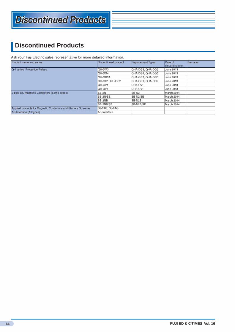
FUJI ED & C TIMES Vol. 16
Discontinued ProductsDiscontinued Products
44
Discontinued Products
Ask your Fuji Electric sales representative for more detailed information.Product name and series Discontinued product Replacement Types Date of
discontinuationRemarks
QH series Protective Relays QH-DG3 QHA-DG3, QHA-DG5 June 2013QH-DG4 QHA-DG4, QHA-DG6 June 2013QH-GR3A QHA-GR3, QHA-GR5 June 2013QH-OC1, QH-OC2 QHA-OC1, QHA-OC2 June 2013QH-OV1 QHA-OV1 June 2013QH-UV1 QHA-UV1 June 2013
2-pole DC Magnetic Contactors (Some Types) SB-2N SB-N2 March 2014SB-2N/SE SB-N2/SE March 2014SB-2NB SB-N2B March 2014SB-2NB/SE SB-N2B/SE March 2014
Applied products for Magnetic Contactors and Starters SJ series SJ-0TG, SJ-0AGAS-Interface (All types) AS-Interface

Safety Considerations•Forsafeoperation,beforeusingtheproductreadtheinstructionmanualorusermanualthatcomeswiththeproductcarefullyorconsultthe
Fuji sales representative from which you purchased the product.•Productsintroducedinthiscataloghavenotbeendesignedormanufacturedforsuchapplicationsinasystemorequipmentthatwillaffect
human bodies or lives.•Customers,whowanttousetheproductsintroducedinthiscatalogforspecialsystemsordevicessuchasforatomic-energycontrol,
aerospaceuse,medicaluse,passengervehicle,andtrafficcontrol,arerequestedtoconsulttheFujisalesdivision.•Customersarerequestedtopreparesafetymeasureswhentheyapplytheproductsintroducedinthiscatalogtosuchsystemsorfacilities
that will affect human lives or cause severe damage to property if the products become faulty.•Forsafeoperation,wiringshouldbeconductedonlybyqualifiedengineerswhohavesufficienttechnicalknowledgeaboutelectricalworkor
wiring.
5-7, Nihonbashi Odemma-cho, Chuo-ku, Tokyo 103-0011, Japan
URL http://www.fujielectric.co.jp/fcs/eng
Information in this catalog is subject to change without notice. Printed in Japan 2014-7 PDF FOLS 62B9-E-0006a