ecu planning and design guidelines
TRANSCRIPT

Edith Cowan University Digital and Campus Services
Planning and Design Guidelines

Planning and Design Guidelines All printed copies uncontrolled March 2021 issue 12 Page 2 of 173
Contents
1.0 INTRODUCTION ......................................................................................................................................... 9
2.0 BUILDING DESIGN .................................................................................................................................... 10
2.1. Campus Master Plans ........................................................................................................................................................ 10
2.2. Precinct Wide Planning ..................................................................................................................................................... 10
2.3. Design Approval Process ................................................................................................................................................... 10
2.4. Delegation & Delegated Authority .................................................................................................................................... 11
2.5. Safety in Design (SiD) ......................................................................................................................................................... 11
2.6. Risk Management .............................................................................................................................................................. 11
2.7. Project Specifications ........................................................................................................................................................ 12
2.8. General Building Design .................................................................................................................................................... 12
2.9. Solar Control ...................................................................................................................................................................... 12
2.10. Wind around Buildings ...................................................................................................................................................... 12
2.11. Space Planning .................................................................................................................................................................. 13
3.0 SUSTAINABLE DESIGN .............................................................................................................................. 15
3.1. Introduction ...................................................................................................................................................................... 15
3.2. Environmental Performance Indicators ............................................................................................................................ 15
3.3. Design Process ................................................................................................................................................................... 16
3.4. Preliminary Analysis .......................................................................................................................................................... 17
3.5. Climate .............................................................................................................................................................................. 18
3.6. Establishment of Sustainability Targets ............................................................................................................................. 18
3.7. Schematic Design .............................................................................................................................................................. 20
3.8. Detailed Design and Documentation................................................................................................................................. 21
3.9. Construction and Commissioning ...................................................................................................................................... 22
3.10. Post Occupancy Evaluation ............................................................................................................................................... 22
4.0 ACOUSTIC REQUIREMENTS ...................................................................................................................... 27
4.1. Acoustic Terminology ........................................................................................................................................................ 27
4.2. Compliance with Codes and Standards ............................................................................................................................. 27
4.3. Implementation for Existing Facilities ............................................................................................................................... 28
4.4. Planning ............................................................................................................................................................................. 28
4.5. Environmental Regulations (Noise) ................................................................................................................................... 28
4.6. Indoor Ambient Noise Levels............................................................................................................................................. 29
4.7. Mechanical Acoustics ........................................................................................................................................................ 31
4.8. Hydraulic Noise ................................................................................................................................................................. 32
4.9. Hearing Conversation ........................................................................................................................................................ 32
4.10. Acoustic Isolation .............................................................................................................................................................. 33

Planning and Design Guidelines All printed copies uncontrolled March 2021 issue 12 Page 3 of 173
4.11. Speech Privacy ................................................................................................................................................................... 38
4.12. Reverberation Control ....................................................................................................................................................... 39
4.13. Room Acoustics ................................................................................................................................................................. 41
4.14. Vibration ............................................................................................................................................................................ 41
4.15. Construction Noise ............................................................................................................................................................ 42
5.0 DESIGN FOR ACCESS AND INCLUSION ...................................................................................................... 43
5.1. Introduction ...................................................................................................................................................................... 43
5.2. Reference Documents ....................................................................................................................................................... 44
6.0 SPECIALIST FACILITIES .............................................................................................................................. 45
6.1. Cleaner’s Store .................................................................................................................................................................. 45
6.2. Toilets ................................................................................................................................................................................ 45
6.3. Courtyards and Indoor Planters ........................................................................................................................................ 45
6.4. Service and Storage Areas ................................................................................................................................................. 46
6.5. Entrances ........................................................................................................................................................................... 46
6.6. Loading Docks .................................................................................................................................................................... 46
6.7. Carparking ......................................................................................................................................................................... 46
6.8. Parenting Room ................................................................................................................................................................. 47
6.9. Laboratories ...................................................................................................................................................................... 48
6.10. Multi Faith Room ............................................................................................................................................................... 48
6.11. Mussallah .......................................................................................................................................................................... 48
6.12. End of Trip Facilities .......................................................................................................................................................... 48
7.0 BUILDING FABRIC .................................................................................................................................... 49
7.1. General .............................................................................................................................................................................. 49
7.2. External Fabric ................................................................................................................................................................... 49
7.3. Internal Walls, Partitions and Finishes .............................................................................................................................. 51
7.4. Floor and Floor Finishes .................................................................................................................................................... 51
7.5. Ceilings and Ceiling Finishes .............................................................................................................................................. 53
7.6. Furniture............................................................................................................................................................................ 53
7.7. Curtains and Blinds ............................................................................................................................................................ 53
7.8. Special Equipment ............................................................................................................................................................. 54
7.9. Door Hardware and Locks ................................................................................................................................................. 54
8.0 SIGNAGE .................................................................................................................................................. 59
8.1. Signage types ..................................................................................................................................................................... 59
8.2. Room Numbering System .................................................................................................................................................. 59
8.3. Braille and Tactile Signage ................................................................................................................................................. 59
9.0 WASTE MANAGEMENT PLAN ................................................................................................................... 60
9.1. Uncleared Land at ECU ...................................................................................................................................................... 60

Planning and Design Guidelines All printed copies uncontrolled March 2021 issue 12 Page 4 of 173
9.2. In-buildings-requirements ................................................................................................................................................. 60
9.3. Suggested Designs for the Different Areas ........................................................................................................................ 61
9.4. Other Bin Requirements .................................................................................................................................................... 61
10.0 BUILDING SERVICES ................................................................................................................................. 64
10.1. Access and Maintenance ................................................................................................................................................... 64
11.0 MECHANICAL SERVICES, HEATING, VENTILATION AND AIR CONDITIONING............................................. 67
11.1. General .............................................................................................................................................................................. 67
11.2. Preferred Contractors ....................................................................................................................................................... 67
11.3. Sustainability ..................................................................................................................................................................... 67
11.4. Design Conditions .............................................................................................................................................................. 67
11.5. Performance Standards ..................................................................................................................................................... 68
11.6. Room Occupancy Number ................................................................................................................................................. 68
11.7. Equipment Loads ............................................................................................................................................................... 68
11.8. Fresh Air Rates................................................................................................................................................................... 69
11.9. Ventilation Requirements ................................................................................................................................................. 69
11.10. Ventilation in Photographic Darkroom Areas .................................................................................................................... 69
11.11. Fire & Smoke Control ........................................................................................................................................................ 70
11.12. Humidity Control ............................................................................................................................................................... 70
11.13. Chilled Water Temperatures ............................................................................................................................................. 70
11.14. Heating Water Temperatures ............................................................................................................................................ 70
11.15. Condenser Water Temperatures ....................................................................................................................................... 70
11.16. Noise and Vibration Control .............................................................................................................................................. 71
11.17. Air Handling Systems ......................................................................................................................................................... 71
11.18. Chilled Water Systems ....................................................................................................................................................... 72
11.19. Heating Water Systems ..................................................................................................................................................... 74
11.20. Ductwork and Registers..................................................................................................................................................... 75
11.21. Piping, Valves and Fittings ................................................................................................................................................. 76
11.22. Insulation to Pipework ...................................................................................................................................................... 77
11.23. Underground Services ....................................................................................................................................................... 77
11.24. Plant and Equipment ......................................................................................................................................................... 78
11.25. Instruments ....................................................................................................................................................................... 82
11.26. Air Conditioning Electrical System ..................................................................................................................................... 82
11.27. Identification of Equipment .............................................................................................................................................. 83
11.28. Identification of Pipework ................................................................................................................................................. 83
11.29. Future Air Conditioning ..................................................................................................................................................... 83
11.30. Building Management System (BMS) ................................................................................................................................ 83
11.31. Air Conditioning Controls – General .................................................................................................................................. 84

Planning and Design Guidelines All printed copies uncontrolled March 2021 issue 12 Page 5 of 173
11.32. Air Conditioning Control Functionality .............................................................................................................................. 84
11.33. Load Shedding ................................................................................................................................................................... 94
11.34. Energy Management ......................................................................................................................................................... 95
11.35. Gas Meters/BMS Connection ............................................................................................................................................ 95
11.36. Practical Completion ......................................................................................................................................................... 95
11.37. Defects Warranty Period ................................................................................................................................................... 96
12.0 HYDRAULIC SERVICES .............................................................................................................................. 97
12.1. Preferred Contractors ....................................................................................................................................................... 97
12.2. Piped Pressure Services ..................................................................................................................................................... 97
12.3. Pipework ......................................................................................................................................................................... 101
12.4. Pumps .............................................................................................................................................................................. 102
12.5. Inspection and Testing .................................................................................................................................................... 102
12.6. Sanitary Plumbing ........................................................................................................................................................... 103
12.7. Stormwater Drainage ...................................................................................................................................................... 104
12.8. Backflow Prevention........................................................................................................................................................ 105
12.9. Fixtures ............................................................................................................................................................................ 106
12.10. Tanks and Hot Water Systems ......................................................................................................................................... 107
12.11. Water Meters .................................................................................................................................................................. 108
12.12. BMS Control Points ......................................................................................................................................................... 108
13.0 LIFT SERVICES ........................................................................................................................................ 109
13.1. Preferred Contractors ..................................................................................................................................................... 109
13.2. Lift Contracts ................................................................................................................................................................... 109
13.3. Lift Dimensions ................................................................................................................................................................ 109
13.4. Types of Lift ..................................................................................................................................................................... 109
13.5. Security ............................................................................................................................................................................ 109
13.6. Facilities for Persons with Disabilities ............................................................................................................................. 110
13.7. Lift Car ............................................................................................................................................................................. 110
13.8. Lightning Surge Diverters ................................................................................................................................................ 111
13.9. Emergency Lighting ......................................................................................................................................................... 111
13.10. Lift Machine-Room .......................................................................................................................................................... 111
13.11. Keys ................................................................................................................................................................................. 112
13.12. Manual ............................................................................................................................................................................ 112
13.13. Maintenance & Warranty ................................................................................................................................................ 112
13.14. Identification of Equipment ............................................................................................................................................ 112
14.0 ELECTRICAL SERVICES ............................................................................................................................ 113
14.1. Preferred Contractors ..................................................................................................................................................... 113
14.2. Sustainability ................................................................................................................................................................... 113

Planning and Design Guidelines All printed copies uncontrolled March 2021 issue 12 Page 6 of 173
14.3. Scope ............................................................................................................................................................................... 113
14.4. Flexibility of Design ......................................................................................................................................................... 113
14.5. RCD Protection ................................................................................................................................................................ 113
14.6. Lighting ............................................................................................................................................................................ 113
14.7. Switching ......................................................................................................................................................................... 115
14.8. Power .............................................................................................................................................................................. 121
14.9. General Wiring ................................................................................................................................................................ 125
14.10. Emergency Lighting ......................................................................................................................................................... 126
14.11. Exit and Stair Lighting ...................................................................................................................................................... 127
14.12. Lightning Protection ........................................................................................................................................................ 127
14.13. Electric Fans and Fan Heaters .......................................................................................................................................... 127
14.14. Toilets .............................................................................................................................................................................. 127
14.15. Tea Rooms ....................................................................................................................................................................... 128
14.16. Gas Meters ...................................................................................................................................................................... 128
14.17. Distribution System ......................................................................................................................................................... 128
14.18. Clock System ................................................................................................................................................................... 128
14.19. Electric Water Heaters and Circulating Pump ................................................................................................................. 128
14.20. Underground Services and Pits ....................................................................................................................................... 128
14.21. Substations ...................................................................................................................................................................... 129
14.22. Regulatory Authority Notices .......................................................................................................................................... 129
14.23. Auto Doors ...................................................................................................................................................................... 130
15.0 COMMUNICATIONS ............................................................................................................................... 131
15.1. Generally ......................................................................................................................................................................... 131
15.2. Cabling Provisions ........................................................................................................................................................... 131
15.3. Detailed Requirements .................................................................................................................................................... 133
15.4. Facility Cabling and Patch Leads ...................................................................................................................................... 138
15.5. Labelling and Documentation ......................................................................................................................................... 140
15.6. Acceptance, Testing Certification and Warranties .......................................................................................................... 141
15.7. Media Services ................................................................................................................................................................ 142
15.8. Contractors and Equipment ............................................................................................................................................ 143
15.9. Antennae ......................................................................................................................................................................... 143
15.10. Security of Equipment ..................................................................................................................................................... 143
16.0 FIRE SERVICES ........................................................................................................................................ 144
16.1. General ............................................................................................................................................................................ 144
16.2. Preferred Contractors ..................................................................................................................................................... 144
16.3. Fire Alarms ...................................................................................................................................................................... 145
16.4. Automatic Fire Alarms ..................................................................................................................................................... 145

Planning and Design Guidelines All printed copies uncontrolled March 2021 issue 12 Page 7 of 173
16.5. Hydrants and Hose Reels ................................................................................................................................................. 146
16.6. Fire Extinguishers ............................................................................................................................................................ 147
16.7. Fire Blankets .................................................................................................................................................................... 148
16.8. Automatic Fire Sprinklers ................................................................................................................................................ 148
16.9. Special Systems ............................................................................................................................................................... 148
17.0 SECURITY SERVICES ............................................................................................................................... 149
17.1. General ............................................................................................................................................................................ 149
17.2. Crime Prevention through Environmental Design (CPTED) ............................................................................................. 150
17.3. Electronic Access Control Systems .................................................................................................................................. 150
17.4. Electronically Operated Door Locks & Hardware ............................................................................................................ 151
17.5. Card Control .................................................................................................................................................................... 153
17.6. Closed Circuit Television .................................................................................................................................................. 154
17.7. Intrusion Alarm Systems .................................................................................................................................................. 157
17.8. Field Hardware Communications .................................................................................................................................... 158
17.9. Key and Locker Management .......................................................................................................................................... 158
17.10. Power .............................................................................................................................................................................. 158
17.11. Fire Monitoring and Emergency Management ............................................................................................................... 159
17.12. Space management ......................................................................................................................................................... 159
17.13. Documentation ............................................................................................................................................................... 159
17.14. Acceptance Testing and Certification .............................................................................................................................. 160
18.0 COLOUR CODING – PLANT AND EQUIPMENT ......................................................................................... 161
18.1. Pumps .............................................................................................................................................................................. 161
18.2. Air-Handling Plants .......................................................................................................................................................... 162
18.3. Air-Compressors and Vacuum Pumps ............................................................................................................................. 162
18.4. Refrigeration Systems ..................................................................................................................................................... 163
18.5. Electrical .......................................................................................................................................................................... 163
18.6. Pipework, Valves and Fittings (not Outlets) .................................................................................................................... 164
18.7. Supports .......................................................................................................................................................................... 164
19.0 EXTERNAL WORKS ................................................................................................................................. 165
19.1. General ............................................................................................................................................................................ 165
19.2. Planting ........................................................................................................................................................................... 165
19.3. Mulching .......................................................................................................................................................................... 165
19.4. Turf .................................................................................................................................................................................. 166
19.5. Irrigation .......................................................................................................................................................................... 166
19.6. Paving .............................................................................................................................................................................. 167
19.7. Decking ............................................................................................................................................................................ 167
20.0 CAD DOCUMENTATION PROTOCOL ....................................................................................................... 168

Planning and Design Guidelines All printed copies uncontrolled March 2021 issue 12 Page 8 of 173
20.1. General ............................................................................................................................................................................ 168
21.0 APPENDICES .......................................................................................................................................... 169
21.1. TEFMA allocation and design standards by room type ................................................................................................... 169
21.2. 210205 T&L Space Standards v3.1 UoF ........................................................................................................................... 169
21.3. Teaching Learning and Student Service Spaces extract ................................................................................................... 169
22.0 Appendix 1 ............................................................................................................................................ 170
23.0 Appendix 2 ............................................................................................................................................ 171
24.0 Appendix 3 ............................................................................................................................................ 172

Planning and Design Guidelines All printed copies uncontrolled March 2021 issue 12 Page 9 of 173
1.0 INTRODUCTION
These Planning and Design Guidelines (“Guidelines”) establish the standards and objectives for the planning,
design, documentation and construction of facilities for Edith Cowan University.
The Guidelines reinforce the University’s objective to be at the forefront of tertiary education, providing learning
opportunities for students supported by current technologies and contemporary facilities.
Consultants are encouraged to recommend solutions that exceed the standards, in particular where the
advantages improve:
Education outcomes
Precinct planning principles
Safety in Design
Constructability
Fit for purpose
Maintainability cost
Time
Quality
Mitigation of University risk
Environmental impacts
The Guidelines require conformity to all relevant Australian Standards, statutory building requirements and
supplementary standards applicable to ECU projects. Where applicable these are referenced in the Guidelines.
Dependent on the type and scale of project, Consultants should liaise with the University and seek agreement as
to which sections of this document are relevant.
This document should be read in conjunction with other relevant documentation made available by the Digital
and Campus Services, including Campus Master Plans incorporating precinct planning. This information is
available through the University’s website at:
https://intranet.ecu.edu.au/staff/centres/facilities-and-services/our-services/campus-planning/master-planning

Planning and Design Guidelines All printed copies uncontrolled March 2021 issue 12 Page 10 of 173
2.0 BUILDING DESIGN
2.1. CAMPUS MASTER PLANS
For each of its campuses, the University has prepared master plans and these will be available once approved
through the Digital and Campus Services link on the University’s website. The University’s master plans provide
information on:
Environmental sustainability
Interface with the wider community
Movement and services corridors
Form & space, including levels across campuses
Steps for future development
The Consultant Team is required to thoroughly review the master plan information and consider as part of the
planning and design process.
2.2. PRECINCT WIDE PLANNING
Generally, designs should actively respond to key urban design principles, when considering the design of a
building within a wider precinct. These key principles could include, but not limited to, the following:
Climate & site
Interface with the public domain
Context in relation to the precinct
Architectural character
Activation of building edges
Safety, security and surveillance
Access and egress (i.e. building users & maintenance)
Campus wide services infrastructure
Wayfinding
Parking and pedestrian movements
Acoustic considerations
The aforementioned principles are relevant to the University’s Campus Master Plans and should be analysed
throughout the building design process.
The Consultants are to clearly detail how the above considerations have been dealt with through and present as
part of design reports at design approval gateways.
2.3. DESIGN APPROVAL PROCESS
The University has a step-by-step “gateway” process for design approvals. This process is to be followed to ensure
that Digital and Campus Services and User Groups are involved during the design and their sign-off and acceptance
of the design is provided. A typical process is summarised below as follows but may vary with the consent of
Digital and Campus Services if the nature of the project warrants it:

Planning and Design Guidelines All printed copies uncontrolled March 2021 issue 12 Page 11 of 173
Gateway 1 - Project Brief
Gateway 2 - Concept Design
Gateway 3 – Schematic Design
Gateway 4 – Design and Contract Documentation
Gateway 5 – Tender
Gateway 6 – Construction
Gateway 7 – Defects Liability
At each gateway the Consultants may be required to submit a design report to the University for review, comment
and sign-off. In line with this submission, the Consultants may be required to present to University.
2.4. DELEGATION & DELEGATED AUTHORITY
As part of the design approval process, the Consultant Team will need to understand the University’s delegation
process and protocols. Further information on levels of delegated authority and respective personnel at the
University is available at:
http://intranet.ecu.edu.au/staff/centres/office-of-governance-services/our-services/delegations
Delegated authority is not provided to any member of the Consultant Team, unless advised in writing and
approved by the University.
2.5. SAFETY IN DESIGN (SID)
The University recognises the importance of planning and design of Projects being undertaken with the
consideration of safe construction and maintenance practices. On this basis the Consultants are required to
undertake Safety in Design (SiD) reviews throughout the planning and design process, identifying risks, mitigation
strategies and latent issues for consideration by the Contractor during construction and the University following
handover and building use. The outcomes of these reviews can be in the form of either reports or matrices and
should be workshopped with the University as appropriate.
SiD reviews are to be undertaken throughout design phases, incorporated into “gateway” reports and evolve
based on the level of design at respective milestones.
SiD reviews will be handed over to Contractors following Contract Award, integrated into their management plans
and risk management process, for future updating and handover to the University for its internal facilities
management processes.
For further information, the Consultants should refer to the relevant codes and practices to understand the
requirements of safe design and obligations of the consultants.
2.6. RISK MANAGEMENT
The Consultants are required to be actively involved in the risk management process through planning and design.
This may require:
Attendance and contribution as part of risk management workshops with the University and other
consultants
Input into the project risk management process, identifying key risks and strategies to help mitigate and/or
manage

Planning and Design Guidelines All printed copies uncontrolled March 2021 issue 12 Page 12 of 173
2.7. PROJECT SPECIFICATIONS
As part of the preparation of Project Specifications by the Consultant Team, a review of the proposed Project
Specifications against this document will be undertaken by the Consultant Team and presented as part of the
Design Report prior to proceeding to tender.
Any departures from this document, noted within the Specifications will need to be approved by the University.
2.8. GENERAL BUILDING DESIGN
Generally,
The design and construction of each building shall be economical in use of space.
Materials must be of a quality commensurate with the building’s purpose and longevity, and take into
account future ease of maintenance.
The placing of protruding building services and equipment on building facades and rooftops should be
avoided wherever possible.
Flexibility for future use of building spaces is to be considered an important design parameter and the
probable effect on the building and services requirements is to be assessed in relation to future change of
use.
Load bearing built elements that restrict future flexibility should be confined wherever possible to the
building core or external walls leaving the interior open and uncluttered.
Consideration must be given to the space allocation for services reticulation horizontal and vertical
tunnels/ducts and ceiling voids to ensure ease of access for maintenance and future changes.
External walls, especially off-form concrete walls, are to be ‘anti-graffiti’ treated to 2.5m high or agreed
height with Project Manager with a non-sacrificial coating. Where a building has concrete external walls,
power and data conduits should be pre-installed where appropriate.
Life cycle costs must be minimised as University buildings are to endure for at least 50 years. For life cycle
costing analysis, the University recommends a 7% discount rate over a life of 20 years.
Building design should take into account the surrounding landscape and public realm, with the intent of
integrating and activating these spaces as best as possible. This is dependent on the type of use of building.
Intuitive wayfinding principles should be adopted wherever possible and not just rely on applied signage in
aiding navigation around buildings and across campuses
2.9. SOLAR CONTROL
(Refer also Functional Controls, Section 2.3 and the University's Standard Building Environmental Brief).
Architects must design to screen against solar heat and glare (especially from lower level roofs) on the faces of
their buildings and to avoid reflection problems for adjacent buildings. Ensure external façade design prevents or
minimises the transfer of radiant heat to the interior and thereby affecting the useable space.
Internal roller blinds can be used for additional solar control but these should not be the primary method.
Generally they should be manually controlled and allow a level sight through of which is best achieved with darker
colours. A metallic backing should be considered to reflect any radiant heat from the glazing. Only in specialist
circumstances on a case by case basis should blackout blinds and motorised blinds be considered.
2.10. WIND AROUND BUILDINGS
For an individual building or groups of buildings architects shall design to avoid problems of wind turbulence.
Appropriate analysis / modelling should be undertaken to determine whether issues are present and how they
are to be managed through design.

Planning and Design Guidelines All printed copies uncontrolled March 2021 issue 12 Page 13 of 173
Design to ensure no wind tunnel /vacuum issues within ground floor lobby or lift risers which restrict use of entry
doors or lift doors as well as noise transfer from wind in to building
2.11. SPACE PLANNING
2.11.1. KEY DESIGN PRINCIPLES
The following principles are intended to guide the design intent but not be a prescriptive direction.
ECU aims to provide spaces for all users that are engaging, considered, fit for purpose, and created to inspire
the occupants in whatever endeavour they are engaged in.
Spaces should be as flexible as possible to ensure that future pedagogical and work practices can be
accommodated without high refurbishment costs. Specialist spaces will be designed to meet the particular
requirements of that school but the principle of flexibility still needs to be considered.
The design of spaces must always take into account the requirements of a wide cross-section of physical
abilities and cultural backgrounds, and produce environments that promote inclusivity, equity and diversity.
Materials and finishes must be chosen that are commensurate with their intended use and of good quality
whilst keeping in mind the project budget. The materials and finishes and design principles will be different
if designing for a teaching environment, and public interface, or a back of house facility for example.
Materials and systems should be chosen to minimise future maintenance and replacement costs over the
course of their intended life span.
Due consideration must be given to the acoustic requirements of the space
2.11.2. GUIDELINES
Like other Universities, ECU benchmarks against the Tertiary Education Facilities Management Association
(TEFMA) guidelines (Edition 3). A copy can be provided by ECU for reference if required. The TEFMA guideline can
be used to inform the design proposal but the requirements of the functional brief will also dictate the outcome
to a degree. A review of the TEFMA standards and how they relate to the requirements of the University is
currently underway.
When considering the application of TEFMA standards, be cognisant of the requirement to adhere to codes such
as Australian Standards, The National Construction Code (NCC), the functions to be accommodated in the space,
and the constraints of the building fabric.
2.11.3. PROFESSIONAL, ACADEMIC AND RESEARCH WORK SPACES
Open plan workspaces are preferred when designing a contemporary workplace. An open plan
environment offers space efficiencies, promotes the easy flow of communication and knowledge sharing,
and it accommodates different ways of working such as autonomous, individual work, to collaborative work
based on the immediate exchange of information and quick decision-making. Meeting rooms, focus rooms,
collaboration and breakout areas, all promote flexible meeting opportunities and opportunities for quiet
work. Flexibility is a key feature of this design and the removal of physical walls and large storage areas will
allow for the adaptable use of space. The needs of the workplace are evolving at a rapid rate and the
workplace needs to be able to respond to these changes without a large cost or substantial disruption.
As a benchmark, the goal for open plan workplace density is a maximum of 13 sqm per person and is based
on Government Office Accommodation standards and common industry practice. This figure is calculated
by simply dividing the total net usable area by the number of workpoints and includes all meeting rooms,
breakout space, circulation and storage space. Specialist areas within the workspace which are considered
over and above what is normally required of a workspace such a laboratory, are not included in this space
density calculation. The density can be increased to accommodate various work functions but this will
ultimately be constrained by the building infrastructure and services, and by code requirements.

Planning and Design Guidelines All printed copies uncontrolled March 2021 issue 12 Page 14 of 173
FTE staff are to be allocated one desk at one campus only. If work is undertaken at another campus then
staff are required to utilise either a bookable hotdesk. The requirement for an assigned desk for part-time
staff will need to be reviewed on a case by case basis.
Sessional staff are required to use a bookable hotdesk.
Where facilities such as breakout rooms, meeting rooms, and stores are shared by multiple schools or
centres, these can be accounted for in the space calculation on a pro rata basis.
Private office space will sometimes be needed but these will be provided on a case by case basis. Other
opportunities for private and quiet work needs to be provided where individual office space is not available.
These standards are intended to be applied when fitting out new spaces and refurbishing existing, and when
looking for space efficiencies.
2.11.4. TEACHING AND LEARNING SPACES
ECU is currently determining the required area of Teaching and Learning spaces and the associated capacity by
referring to the TEFMA guidelines which can be viewed in the appendices – “TEFMA Allocation and Design
Standards by Room Type”. A review of these requirements is currently underway.
Additionally, the University has produced a set of Teaching Learning Space Standards. These standards list the
technical requirements for all Teaching and Learning spaces. For more information refer to the appendices –
“210205 T&L Space Standards v3.1 UoF”
Also refer to the appendices for “Teaching Learning and Student Service Spaces extract”. This document gives a
useful insight into the conceptual and pedagogical drivers behind the types of spaces that will now be required
for Teaching and Learning areas. The pages set out ECU’s current vision for how teaching, learning and service
spaces would operate in the new City Campus currently under development. This vision will necessarily evolve in
response to both the lead architects’ experience and input, and also the transformative work occurring under the
University of the Future Project.
ECU is also using international benchmarks such as the “Learning Space Rating System”. It is not publically
available but a copy can be provided by ECU if requested.
2.11.5. SPECIALIST SPACES
These are spaces that are generally operationally managed by a school and have particular functions that separate
them from general teaching spaces, such as laboratories and dance studios. The spatial requirements of these
spaces will vary according to their particular function but for a general guide, refer to “TEFMA Allocation and
Design Standards by Room Type” in the Appendices.
2.11.6. GENERAL SPACES
This encompasses a variety of spaces, some of which are referred to in the “TEFMA Allocation and Design
Standards by Room Type” in the Appendices.
It also includes general circulation and gathering spaces, and areas defined as “Non-useable Floor Areas” such as
services areas and ducts and toilets. Note that many of these areas are defined by code requirements.

Planning and Design Guidelines All printed copies uncontrolled March 2021 issue 12 Page 15 of 173
3.0 SUSTAINABLE DESIGN
Section to be reviewed by consultant. Highlighted areas also under review
3.1. INTRODUCTION
The purpose of these Sustainability Guidelines is to provide guidance to designers in respect to Ecological
Sustainable Design (“ESD”). ESD means to design buildings with longevity and minimal impact on the existing
biodiversity and there are three key ways to achieve this:
a) Compliance with the six environmental performance indicators, see section 3.2.
b) Incorporating Green Star building design features to a minimum standard of 4 stars with the target of
reaching 5 stars. Please see section for further info on how ECU incorporates Green Star features into
its building design. Please note ECU does not apply for Green Star accreditation certificates but does
aim to incorporate green star design features into its building design.
c) Meeting the requirements for design documentation and review according to the process shown in
section 3.3.
This document provides a step-by-step guide which will allow the design to be reviewed prior to proceeding to
the next stage of design development. However this section is not a complete guide to the sustainable features
to be included in building design and for a complete understanding of sustainable building features this section
must be read in conjunction with other sections of the Guidelines.
This document is a guide to the various green building approaches and technologies available to designers. There
are many guidelines and case studies, and much literature on this subject, and designers are expected to be aware
of best practice and able to apply it to ECU projects.
3.2. ENVIRONMENTAL PERFORMANCE INDICATORS
The following environmental performance indicators established by ECU are to apply to all building projects.
Additional indicators may be established for specific projects.
Thermal Comfort
Objective: To ensure the thermal comfort of building occupants in normal operating conditions Indicator: Predicted Mean Vote (PMV) as measured in accordance with ISO 7730 Target: PMV in the range of -1 to +1 Indoor Air Quality
Objective: To ensure indoor air is free from contaminants and contains ample amounts of fresh air Indicator: Indoor CO2 concentration Target: 700 ppm (average over 8 hour period) Materials Intensity
Objective: To minimise the energy embodied in construction materials Indicator: Embodied Energy (GJ/m2) as calculated in accordance with Appendix 1 (a) Target: To be established during the Concept Design phase [Nominally in the range 14-18 GJ/m2] Operational Energy Consumption
Objective: To minimise the total energy consumed within the building Indicator: Energy consumption (MJ / m2 pa) calculated in accordance with Appendix 1 (b) Target: To be established during the Concept Design phase [Nominally in the range 290-323 MJ / m2 pa]

Planning and Design Guidelines All printed copies uncontrolled March 2021 issue 12 Page 16 of 173
Greenhouse Gas Emissions
Objective: To minimise the emissions of greenhouse gases from energy sources Indicator: Greenhouse emissions (T CO2-e / m2) to be calculated in accordance with Appendix 1 (c) Target: To be established during the Concept Design phase [Nominally in the range 79-88T CO2-e / m2] Scheme Water Consumption
Objective: To minimise the consumption of water from scheme sources Indicator: Potable water consumption (L / day /m2) to be calculated in accordance with Appendix 1 (d) Target: To be established during the Concept Design phase
[Nominally in the range 0.20 - 0.25 L / day /m2]
3.3. DESIGN PROCESS
Optimal sustainability outcomes will only be achieved through an integrated design approach which involves
collaboration between all consultants at all stages of design.
The Consultants will establish working arrangements which establish clear design responsibilities for each of the
sustainability objectives, including how multi-disciplinary teams will work together to achieve the desired
outcomes.
The steps and design process to achieve the final design are as follows:
Step 1: Preliminary Analysis
Step 2: Establishment of Sustainability Targets (incorporated into the Project Brief)
Step 3: Concept Design
Step 4: Schematic Design
Step 5: Detailed Design and Documentation
Step 6: Construction and Commissioning
Step 7: Post Occupancy Evaluation
The sustainability objectives are to be defined during the Briefing stage of the project, with clear indication of
how each of the targets are to be reported against at each stage of the abovementioned process.
Further explanation of each stage is contained in the following sections.

Planning and Design Guidelines All printed copies uncontrolled March 2021 issue 12 Page 17 of 173
Figure 1: Flow chart showing the design process:
3.4. PRELIMINARY ANALYSIS
A full analysis of all factors affecting the design is required before the process of developing building concepts is
commenced. Figure 1 sets out the issues to be considered. A brief report setting out the findings of this analysis
shall be provided to ECU prior to commencement of Concept Design. Although this analysis will be relevant to
many aspects of design, the report should particularly establish the opportunities for, and constraints to,
achievement of sustainability objectives.
In particular the following should be carefully evaluated during the analysis phase in respect of sustainability
opportunities / constraints.
Site
Geotechnical Conditions: Opportunities for ground coupling, groundwater for non-potable water, presence of rock material impacting
structural design considerations
Environmental Conditions Understanding of whether ground conditions pose a risk to health or the environment, resulting in landfill disposal
requirements and importation of clean fill material from off-site sources
Ecology: Protection of important ecological assets including existing vegetation and trees with significant habitat features
are to be incorporated into building design
Preliminary
Analysis
Functional
Requirements
Facilities
Landscape
Parking
Site
Geotech
Ecology
Topography
External factors
Climate
Temperature
Humidity
Wind
Rainfall
Solar insolation
Micro-climates
Site Context
Planning policies
Roads
Landscape
Ecology
Sustainability
Performance
Objectives
Benchmark
against ECU Core
Performance
Indicators
Thermal comfort
Air quality
Materials intensity
Energy
consumption
Greenhouse
emissions
Potable water
consumption
Green Rating
Systems
Green Star
Concept Design
Case Studies /
Research
Performance of
Existing ECU
Buildings
Building Form
Building height
Thermal Mass
Openings / Glazing
Shading
Insulation
Passive Ventilation
Building Plan /
Sections
Location on site
Space
Configuration
Orientation
Relationship with
other bldgs
Sustainability
Targets
determine
and
and
Passive Indoor
Environmental
Performance
Thermal comfort
Air quality
Light
Views
Computer modelling
Active Systems
Performance
Criteria
Mechanical
Electrical
District
Infrastructure
Water
Wastewater
Drainage
Power
Telecoms
and establish
Building Systems
Concepts
Ventilation
Heating / Cooling
Lighting
Fire
Communications
to select
Concept Design
to produce
review against / modify
Schematic
Design
Detailed Design
and
Documentation
Construction
Computer
modelling
Evaluate options to
minimise active
systems capacities
Refine Building
Systems
Ventilation
Heating / Cooling
Water
Wastewater
Lighting
Fire
Communications
Schematic
Design
Design
Optimisation
Building Plan /
Sections
Building Form
Materials
Building Systems
Site Infrastructure
Evaluation /
Computer
Modelling of
Building
Performance
against
Sustainability
Targets
Rating Scheme
Documentation
Design
Contract
Documentation
Review
Contractor’s
Submissions
Equipment
Materials
Construction
Waste
Management Plan
Building
System’s
Commissioning
Building Users
Guide
Operations and
Maintenance
Manuals
Post occupancy
evaluation
Design Report
Design Report
Construction
Addendum
Post Occupancy
Evaluation
To optimise
Preliminary / sketch design
Materials
Structural system
Building envelope
Design
Development
Building Plan /
Sections
Building Form
Materials
Site
Infrastructure
Water
Wastewater
Drainage
Power
Telecoms
Building Systems
Commissioning
and Management
Review
Finalise Building
Design Solution

Planning and Design Guidelines All printed copies uncontrolled March 2021 issue 12 Page 18 of 173
Topography Exposure to prevailing winds/storms, opportunities for incorporating existing and proposed topography to create
thermal mass around the building
3.5. CLIMATE
It is ECU’s objective to ensure that all buildings are designed to be responsive to the change in Perth’s climate,
which will require modelling of the design to evaluate performance against the sustainability indicators.
The climate analysis will include:
Average temperatures rising by up to 2°C over the next 30 years. Hotter more humid climatic conditions.
An assessment of the micro-climate at the site will be necessary to ensure that local factors are properly
considered, thermal imagery will be required to identify hot spots in the building.
Existing Infrastructure.
In order to ensure that the concept design properly evaluates opportunities for alternative approaches to service
provision, a thorough analysis of the infrastructure existing on the campus, and in the surrounding area will be
required, including:
Water Maximise the use of rainfall and harvesting water if feasible, minimise the use of groundwater resources and
scheme water. ECU encourages designers to investigate the option of recycling water within buildings.
Wastewater Ensure wastewater infrastructure does not pollute or create contamination to waste water resources. Aim to
reuse wastewater on site where possible to reduce the consumption of scheme water.
Drainage Incorporate rainwater/stormwater capture into building design, consider water sensitive urban design, including
integration into landscape design.
Power Incorporate renewable energy options into building design as a way of reducing carbon emissions and at least 5%
of the total power usage with photovoltaic technology.
Telecoms Communications, building control potential.
3.6. ESTABLISHMENT OF SUSTAINABILITY TARGETS
The results of the preliminary analysis provide an initial evaluation of the constraints and opportunities to meet
and inform ECU’s core sustainability performance objectives. This information should be considered in
conjunction with:
Performance data from other similar ECU buildings, and other relevant education building projects
available;
The Green Star – Education rating tool, the NABERS scheme and other relevant green building evaluation
schemes; and
Best practice examples of sustainable building design in Australia or overseas.
This information will be used to confirm / expand the core performance objectives and indicators set out above,
and determine appropriate targets for each indicator. This process will occur in a workshop involving key
members of the Consultant team and ECU, and be documented.

Planning and Design Guidelines All printed copies uncontrolled March 2021 issue 12 Page 19 of 173
Targets will be set on the basis of both environmental performance and project cost, including the impacts on
project quality outcomes. Although the cost implications of various targets may not be able to be accurately
assessed at this stage, a qualitative estimate of both capital and life cycle costs shall be made.
At this stage, before any significant design analysis has commenced, it may not be possible to set targets for all
indicators, e.g. energy consumption or greenhouse gas emissions. In this case an interim target will be set, and
confirmed or modified at a later stage of the design. Initial advice should be sought from the appropriate
consultant to set interim targets based on the specific building type.
3.6.1. CONCEPT DESIGN
During the early stages of the Concept Design phase an emphasis should be placed on developing a building plan
that optimises the passive performance of the building, and hence minimises the loads on the active building
systems, particularly heating, cooling, ventilation and lighting. This process is the foundation of energy efficient
building design.
With the key loads identified, the development of options for building systems will then be undertaken. Building
materials will be selected to achieve the required characteristics in respect of thermal performance and embodied
energy as well as architectural and structural considerations.
The achievement of optimal sustainability outcomes requires a fully integrated design approach, with architects
and engineers working closely together. The following sections outline the key aspects to this integration
3.6.2. PASSIVE BUILDING PERFORMANCE
Without the influence of active systems the key indoor characteristics of a building (thermal comfort, air quality,
light and views) are a function of:
Building Plan/Sections Location on site, Space Configuration, Orientation, Relationship with other buildings etc.
Building Form Building height, Thermal Mass, Openings / Glazing, Shading, Insulation, Natural Ventilation
The Climate Temperature, Humidity, Wind, Rainfall, and Solar isolation.
Consideration of these factors should be central to development of the early concepts. Computer modelling is
likely to be required during this stage to efficiently consider alternative building plans/sections/forms, particularly
with respect to thermal comfort, natural ventilation and day lighting.
This process will be architect-led but will involve Engineering input as required.
A design workshop will be held early in the Concept Phase with ECU to present and discuss alternative building
plans/sections/forms in light of the project’s sustainability indicators and targets, and capital and lifecycle cost
implications.
3.6.3. BUILDING SYSTEMS CONCEPTS
Development of alternative building plans/sections/forms, together with the functional requirements of the
project will establish approximate building system loads, e.g. ventilation, heating / cooling, lighting, fire,
communications.

Planning and Design Guidelines All printed copies uncontrolled March 2021 issue 12 Page 20 of 173
The development of design concepts for ventilation, heating / cooling and lighting will be mainly informed by
thermal comfort, air quality, energy and water efficiency objectives.
3.6.4. MATERIALS
Development of alternative building plans/sections/forms will establish the requirements for materials in respect
of the structural and thermal performance of materials and sections. This, together with the functional
requirements of the project will enable preliminary materials selection to occur.
Options to be evaluated will be mainly informed by the materials intensity objectives, which will require an
understanding of the embodied energy of various materials.
Materials are to be sourced locally and/or from reused materials as a first preference to reduce the embodied
energy of the product. Suppliers to provide information on where the product comes from, how it was made and
to be incorporated into the Environmental Management Plan.
Finalising the Concept
A workshop will be held with ECU just prior to completion of the Concept Design phase. In this workshop the
Consultant Team will present the various alternative concepts considered and discuss their performance against
the following:
The project’s functional requirements;
The sustainability objectives/targets; and
Capital and lifecycle costs
This workshop will confirm the sustainability targets to be achieved on the project, and provide guidance to the
Consultant Team for finalising the Concept Design.
The Concept Design deliverables will include a sustainability report containing the Preliminary Analysis, the
establishment of Project Targets, documentation of the alternatives considered, and a justification of the
proposed Concept based on functional, sustainability, quality and cost considerations.
3.7. SCHEMATIC DESIGN
3.7.1. DESIGN DEVELOPMENT
Further development of the design will involve the refinement of the Building Plan / Sections; the Building Form,
and its Materials.
3.7.2. COMPUTER MODELLING / SIMULATION
Computer modelling will be used to evaluate the environmental performance of the building and to evaluate
options to minimise the capacity of active systems. Energy modelling will follow the Green Star / NABERS Energy
simulation validation protocol.
The modelling will facilitate the refinement of the building systems including Ventilation, Heating / Cooling,
Water, Wastewater, Lighting, Fire Control and Communications. Again, alternative options shall be considered
and compared, using the sustainability targets as a guide.
3.7.3. SITE INFRASTRUCTURE
Consideration of the buildings systems will also inform, and be informed by potential options with respect to site
infrastructure, including Water, Wastewater, Drainage, Power and Telecoms.

Planning and Design Guidelines All printed copies uncontrolled March 2021 issue 12 Page 21 of 173
3.7.4. FINALISING SCHEMATIC DESIGN
A workshop will be held with ECU just prior to completion of the Schematic Design phase. In this workshop the
Consultants will present the various alternative concepts considered and discuss their performance against the
following:
The project’s functional requirements;
The sustainability objectives / targets; and
Capital and lifecycle costs
This workshop will confirm the design solution and provide guidance to the Consultants for documenting the
project. The Schematic Design deliverables will include a sustainability report outlining the process of design
development, documentation of the alternatives considered, and a justification of the proposed Scheme based
on functional, sustainability, quality and cost considerations
3.8. DETAILED DESIGN AND DOCUMENTATION
3.8.1. DESIGN OPTIMISATION
The first part of the documentation phase of the project involves the further refinement of Building Plan /
Sections, Building Form, Materials, Building Systems and Site Infrastructure with a view to optimising the building
as an integrated system.
The optimisation process will involve further computer modelling and other evaluation of the building
performance against the selected sustainability targets.
3.8.2. BUILDING SYSTEMS COMMISSIONING AND MANAGEMENT REVIEW
Prior to finalising the design solution, a review will be undertaken with the participation of ECU to ensure that the
strategy for equipment selection, commissioning of the building systems and their post-construction
management is resolved and agreed, including:
Measurement (including metering);
Control of the building’s active systems;
Commissioning requirements;
Systems monitoring and tuning through the Defects Liability Period, handover to ECU and post occupancy.
3.8.3. CONTRACT DOCUMENTATION
Prior to the completion of the Contract Documentation a review will be undertaken with the participation of ECU
to ensure that the drawings, specifications and contract requirements are comprehensive in respect of the
sustainability elements of the design and will result in the realisation of the sustainability performance targets.
The contract documents will include the requirements of the Contractor in respect of best practice construction
waste management, including the preparation of a Waste Management Plan.
The specifications will include a “Sustainability” section which will set out the sustainability objectives and targets
and outline the relevant design measures with reference to key drawings and specifications, including those
related to commissioning and tuning of the building systems. This will stipulate the requirements of the
Contractor to achieve sustainability targets during construction.
3.8.4. RATING SCHEME DOCUMENTATION
If the project is seeking certification to Green Star or other rating schemes, the preparation of the necessary
documentation will proceed in parallel with the Contract Documentation process.
3.8.5. SUSTAINABILITY REPORT

Planning and Design Guidelines All printed copies uncontrolled March 2021 issue 12 Page 22 of 173
As part of the project deliverables a sustainability report will be prepared which incorporates the reporting at
Concept and Schematic Design stage and outlines the final design solution and how it will achieve the
sustainability objectives and targets.
In particular the report will set out the strategy for measuring, monitoring and management of the building’s
systems and the contractual arrangements for commissioning, tuning and handover to ECU.
3.9. CONSTRUCTION AND COMMISSIONING
3.9.1. CONSTRUCTION MANAGEMENT
Management of the construction phase will be structured to ensure that the sustainability objectives and targets
will be achieved. In particular the following will be considered:
Construction Waste Management Plan - development, approval and monitoring
Environmental Management Plan – development, approval and monitoring
Review Contractor’s Submissions - for equipment and materials
Building System’s Commissioning – preparation and supervision
3.9.2. BUILDING USERS GUIDE
During the construction phase a comprehensive Building Users Guide will be prepared. The guide will describe
the design measures taken to achieve the sustainability targets, outline how the building systems work and
describe how building users and occupants operate the building to ensure optimal performance and efficiency.
The Building Users Guide will be prepared as an online resource suitable for all users and occupiers. It will provide
an appropriate link to detailed Operations and Maintenance Manuals for use by ECU’s facilities management
team.
The Building Users Guide will also include a section on the measures that will be undertaken at post-occupancy
to evaluate the performance of the building as set out below.
3.9.3. SUSTAINABILITY REPORT
An addendum to the sustainability report will be prepared at the time of practical completion, which takes into
account any modifications to the design arising from construction or clarifications necessary following
commissioning and building tuning. This is to be prepared in conjunction between the Consultant Team and
Contractor.
3.10. POST OCCUPANCY EVALUATION
Prior to Practical Completion a workshop will be held involving ECU facilities management staff, the key members
of the design / construction teams and equipment suppliers to establish an appropriate approach to post
occupancy evaluation.
Measures will be identified to evaluate the post-occupancy performance of the building against the required
functional characteristics of the building and the sustainability targets. These measures will involve a combination
of measurement and monitoring of the building’s systems and surveys of occupants and ECU’s facilities
management staff.
The post occupancy evaluation methodology will be incorporated in the Building User’s Guide

Planning and Design Guidelines All printed copies uncontrolled March 2021 issue 12 Page 23 of 173
SUSTAINABILITY APPENDIX
CALCULATION OF EMBODIED ENERGY
Embodied Energy Calculation
An example of a calculation used to determine embodied energy can be found at
http://thegreenestbuilding.org/
Embodied Energy Target Setting
Due to the lack of benchmarked data and potential complexity of embodied energy calculations it is envisaged
that the scope of embodied energy calculations will be limited to the main sources of energy / emissions.
The main focus for target setting is:
To ensure the design achieves better outcomes than conventional practice; and
To compare different building systems / materials selections; rather than the achievement of any particular
target embodied energy figures.
Accordingly it is envisaged that targets will be set as a result of option studies during concept design.
The summary of embodied energy calculations from various case studies by RMIT quotes an EE figure of 15.76
GJ/m2 for an educational facility.

Planning and Design Guidelines All printed copies uncontrolled March 2021 issue 12 Page 24 of 173
Figure 2 – Embodied Energy
ECU B21 Health & Wellness Building - Embodied Energy
Qty Unit EE coeff Unit Embodied Energy
Groundwork
Excavation 1,341 m3 0.036 GJ/m3 48 GJ
Rock excavation 20 m3 0.036 GJ/m3 1 GJ
Fill (sand) 1,040 m3 0.036 GJ/m3 37 GJ
Total 86 GJ
Structural Steel & Metalworks
Steel 994 t 64.6 GJ/t 64,202 GJ
Reinforcing steel 635 t 64.6 GJ/t 41,000
Structural steel 358 t 64.6 GJ/t 23,106
Galvanised steel 1.5 t 64.6 GJ/t 97
Aluminium 569 t 159.5 GJ/t 90,782 GJ
Wall cladding 25 t 159.5 GJ/t 3,985
Sun control screens 519 t 159.5 GJ/t 82,813
External windows and doors 25 t 159.5 GJ/t 3,984
Total 154,985 GJ
Concrete
Concrete 5,130 m3 0.4 GJ/m3 2,052 GJ
Precast concrete 300 m3 0.4 GJ/m3 120
In-situ concrete 4,790 m3 0.4 GJ/m3 1,916
Piles 31 m3 0.4 GJ/m3 12
Cavity fill 10 m3 0.4 GJ/m3 4
Blockwork 80 m2 0.21 GJ/m2 17
Total 2,052 GJ
Building Envelope
Plastering (3:1 ratio) 19 m3 4.4 GJ/m3 83 GJ
Brickwork & Mortar 7,939 m2 0.75 GJ/m2 5,954 GJ
Limestone 34,816 kg 0.3 MJ/kg 10 GJ
Glazing 26 t 13.9 GJ/t 358 GJ
Roofing & Wall Cladding 17 t 64.6 GJ/t 1,089 GJ
Sheet steel 17 t
Carpentry & Joinery
Glasswool batts 6,881 m2 0.097 GJ/m2 667 GJ
Total 8,163 GJ
Paving & Tiling (Internal Finishes)
Carpet 6,991 m2 0.804 GJ/m2 5,621 GJ
Floor vinyl 2,358 m2 0.2 GJ/m2 472 GJ
Wall vinyl 151 m2 0.2 GJ/m2 30 GJ
Ceramic tiles 1,264 m2 0.29 GJ/m2 367 GJ
Stone tiles 17,983 kg 5.9 MJ/kg 106 GJ
Total 6,595 GJ
Total embodied energy 171,881 GJ
Total floor area 10,550 m2
Total Embodied Energy/m2 16,292 MJ/m2
16.3 GJ/m2

Planning and Design Guidelines All printed copies uncontrolled March 2021 issue 12 Page 25 of 173
Exclusions
The following items from the Bill of Quantities were excluded:
Formwork
Stud work wall framing
Waterproofing
Operable walls
Metal door frames
Soffit linings • Handrails & Balustrades
Projection screens
Toilet accessories
Skirting
Carpentry & joinery
Capping and flashings • Gutters
Lift Services
Hydraulic Services
Ceilings, partitions and linings
Mirrors
Painting
Site works
OPERATIONAL ENERGY
Operational Energy Calculation
The calculation of operational energy consumption will be based on energy modelling of the building in
accordance with the Green Star / NABERS Energy simulation validation protocol.
Operational Energy Targets Targets will be set during the concept design phase and shall be based on the achievement or the exceeding of
best practice for the particular type of building under consideration.
It is expected that targets will meet or exceed the “conditional requirements” determined from the Green Star
Education energy calculator.
Green Star – Education v1 Energy Calculator determines the benchmark for each project based on the
composition of space types within each project. The conditional requirements are:
Universities Conditional Requirements (kgCO2-e/m2/annum) Teaching/classroom spaces 82 Dry labs/specialty learning spaces and libraries 88 Office/administrative spaces 79 Common spaces 57 Wet labs (varies based on density of fume cupboards) Gymnasiums 143 Car parks 52
The methodology used to establish the conditional requirement for each space type is detailed in the Green Star
– Education v1.
Energy Calculator Standard Practice Benchmark document available on the GBCA website. The predicted
greenhouse gas emissions must be determined using energy modeling in accordance with the final and current
version of the Green Star – Education v1 Energy Calculator.

Planning and Design Guidelines All printed copies uncontrolled March 2021 issue 12 Page 26 of 173
GREENHOUSE GAS EMISSIONS
Greenhouse Gas Calculation Method
Base calculation – operational energy
Greenhouse gas emissions shall be calculated from the Green Star Education energy calculator. Although the
Green Star calculations include an allowance for on-site renewable energy generation, this should not be included
in the Base calculation.
Net calculation
The net greenhouse calculation shall be the Base calculation, less the following:
The proportion of electrical energy to be purchased under the Green Power scheme in accordance with
ECU’s contemporary environmental policy;
Any onsite renewable energy generation.
Any project specific carbon offset initiative (methodology to be in accordance with the Voluntary Carbon
Standard.
Greenhouse Gas Target
The greenhouse gas target will be set during the Concept Design phase during which options will be considered
for the building’s thermal performance, energy demand management, energy efficient equipment, low carbon
energy sources, renewable energy, ECU’s policy in respect of Green Power purchase and carbon offsets.
It is expected that targets will meet or exceed the “conditional requirements” determined from the Green Star
Education energy calculator.
POTABLE WATER CONSUMPTION
Potable Water Calculation
Potable water consumption shall be calculated from the Green Star Education calculator. The Green Star
calculations include an allowance for on-site rainwater, grey water and black water use but do not include any
provision for use of stormwater or groundwater, and separate account for these sources will need to be made.
Potable Water Targets
The potable water target will be set during the Concept Design phase during which options will be considered for
substituting potable water with rainwater, stormwater, groundwater, grey water and / or black water for
approved non-potable uses in the local jurisdiction.
It is envisaged that the target set will achieve at least 3 points as calculated by the Green Star Education calculator.

Planning and Design Guidelines All printed copies uncontrolled March 2021 issue 12 Page 27 of 173
4.0 ACOUSTIC REQUIREMENTS
The intention of this Acoustic Brief is to establish design standards for the acoustics of new university buildings.
To be reviewed by acoustic consultant with an eye on different future acoustic requirements brought on by access
to new technologies and different ways of presenting information both in teaching and public spaces
4.1. ACOUSTIC TERMINOLOGY
Rw = Weighted Sound Reduction Index (Previously STC – Sound Transmission Class) Is a measure of the acoustic effectiveness of a building partition, door, floor or other building element with
regards to reducing airborne noise transmission from one side of the element to the other (i.e. single pass). This
value is the ‘design rating’ of the element, as established via measurements in an acoustic laboratory in
accordance with relevant Australian Standards. It is often referred to as a measure of the airborne sound
insulation provided between two spaces.
D’ntw = Weighted Standardised Level difference (Previously FSTC) Is similar to the Rw value, except that values are established via field measurements. It is recognised that normal
building tolerances and flanking transmission paths have an effect on building elements when installed, generally
resulting in a reduction in the field measured values. It is common for the D’ntw of a partition system to be
approximately 5 points lower than the Rw results of the same system tested in a controlled laboratory
environment.
Dncw = Weighted suspended ceiling normalised level (Previously CAC) Previously expressed as the Ceiling Attenuation Class, this is a measure of the acoustic effectiveness of a ceiling
system with regards to reducing airborne noise transmission from one room to another, through a common
ceiling space. This value is the laboratory rating of the element, as established via measurements in accordance
with relevant Australian Standards.
LAeq = “A- weighted” equivalent continuous noise level This is the constant sound level over a stated time period, which is equivalent in total sound energy to a variable
sound level over the same time period. Often simply referred to as the ‘average sound level’ for a given time
interval.
Note - Current Australian Standards use Leq noise levels for ‘architectural acoustic’ criteria, including noise from
‘mechanical systems’ etc. Noise Rating (NR) curves previously used for the assessment of noise from mechanical
services are no longer commonly used, and are not included in current Australian Standards.
RT = Reverberation Time RT is a common measure of the acoustical environment achieved in a space. It is the time taken in seconds for
sound energy to decay by 60 dB. Reverberation control is typically required to enable clear speech
communication in spaces, or to control general ‘noisiness’ in open plan and public spaces.
4.2. COMPLIANCE WITH CODES AND STANDARDS
Unless otherwise required, the consultant shall execute all work undertaken in accordance with the relevant
Australian Standards, Building Codes, Acts, etc. and the Building Code of Australia.
However, many acoustic standards are not covered by the above and if not already included in this Design Brief,
will need to be specifically developed by the consultant for the project (in consultation with the appropriate client
representatives) based on the functional use of the building and surrounding facilities / spaces.

Planning and Design Guidelines All printed copies uncontrolled March 2021 issue 12 Page 28 of 173
4.3. IMPLEMENTATION FOR EXISTING FACILITIES
It is recognised that implementation of all acoustic requirements may not be possible in retrofit / refurbishment
of existing buildings. Where major building elements are to be modified, the changes must be in accordance with
current acoustic standards. Where a change affects another space, the acoustic conditions of that space must
not be downgraded. In some cases the other space will require upgrading to meet current standards, dependent
on the usage and scale of works.
4.4. PLANNING
Objective – To ensure that due consideration is given to cost effective planning options that support good acoustic
design, reducing the requirement for more costly technical construction solutions.
There is a diverse range of technical acoustic requirements for spaces throughout university facilities. Planning is
often fundamental in achieving a good acoustic environment within an educational building. It is usually possible
to plan new buildings to avoid expensive technical solutions, in the achievement of acceptable acoustic
conditions. The ‘noise sensitive’ or ‘noise intensive’ nature of specific areas requires careful consideration from
the earliest stages of a design.
Some general planning issues that should be considered at the earliest stages include:
External noise sources such as road traffic or external activities (i.e. public spaces, retail areas, areas subject
to heavy foot traffic).
Noise emission from mechanical equipment and plant rooms, including lift motor rooms, chillers /
condensers, air handling plant, fume / dust extractors, pumps & tanks, etc.
Avoid location of ‘noise sensitive’ spaces adjacent to ‘noise generating’ spaces. For example - keep spaces
with low tolerance to noise intrusion such as private offices and teaching spaces acoustically separated from
noisy spaces such as plant rooms.
4.5. ENVIRONMENTAL REGULATIONS (NOISE)
Objective – To control noise emissions from facilities to meet the requirements of the Environmental Protection
(Noise) Regulations 1997 r 5, 7-9, 11-14A, 14, 15, 16, 16AA, 16BA, 17, 18, 18B, 19B; sched 2, (as amended).
These regulations set the maximum permissible sound level allowed at ‘neighbouring premises’, for various times
of the day. All aspects of these regulations must be met in full. The major design issues to be considered include:
Noise emission from external plant and equipment, including refrigeration plant, chillers / condensers, fume
/ dust extraction, emergency generators etc.
Noise break-out from enclosed mechanical equipment and plant rooms, particularly via ventilation paths.
Breakout noise from enclosed activity areas, including; i) spaces where music or audio equipment are
accommodated ii) spaces incorporating use of workshop type equipment including cut off saws, grinders
and similar.
Noise emission from outdoor activity, including live performance, amplified music etc.
Noise emission from service / loading areas, including driveways.
These issues must be considered at the earliest design stages. In particular, the project Mechanical Consultant
must give due consideration to the location of significant external mechanical plant, and the potential for
environmental noise emissions to neighbouring premises as well as adjacent university buildings.
NOTE: There are no formal regulations or design standards regarding control of noise emissions to pedestrian or outdoor
areas within a property (campus). However, a useful guide to maintain general amenity is as follows:

Planning and Design Guidelines All printed copies uncontrolled March 2021 issue 12 Page 29 of 173
Noise received at façade of adjacent university building; LAeq 50 dB (A)]
Noise received at general transient / pedestrian areas; LAeq 50 dB(A)
Noise received at general purpose courtyards; LAeq 45 dB(A)
It must be noted that these levels will still be considered to be clearly audible when ambient conditions are
otherwise quiet. More stringent requirements may be appropriate for specific outdoor areas such as
amphitheatres or ‘special use’ courtyards etc. Requirements for these spaces are to be determined on a project-
by-project basis.
4.6. INDOOR AMBIENT NOISE LEVELS
Objective – to ensure appropriate indoor ambient noise levels are achieved in various spaces, relative to the
acoustic sensitivity of proposed activity.
The background or ‘ambient’ noise levels within unoccupied spaces shall not exceed the levels set in Australian
Standard AS/NZS 2107 "Acoustics - Recommended Design Sound Levels and Reverberation Times for Building
Interiors".
The ‘design sound levels’ recommended in this standard relate to the background noise level in a room as a result
of noise from the following sources:
Building Services
Ventilation and air-conditioning systems
Hydraulic services / plumbing
Lighting and other fixed electrical equipment
External Sources
Road traffic
Pedestrian traffic / public space use
Neighbouring industrial and commercial operations
Externally located plant
Activity noise from adjacent facilities located on the campus
Activity noise from adjacent spaces Consideration should also be given to the potential noise levels and noise character generated by the normal
range of activities within the building. The control of room-to-room noise transfer is addressed by the airborne
sound insulation requirements defined in section 10 of this Acoustic Brief. This intention is that noise intrusion
as a result of activity noise should not exceed the maximum LAeq levels set out in AS/NZS2107, based on
assessment period of LAeq, 30 min.
Rain Noise Rain noise on metal roofing and stormwater disposal (including box gutters and downpipes) generally requires
special consideration. This issue may require in-depth acoustic design, depending on the use of potentially
effected spaces. As a general guide, noise intrusion to ‘noise sensitive’ spaces such as Lecture Theatres and
general purpose Auditoria should not exceed the recommended ‘design sound levels’, as summarised in Table 1
(below). For Offices and Flexible Learning Spaces, levels up to 5dB above the stated ‘satisfactory’ criteria are likely
to be acceptable.
Table 1 sets out a summary of relevant ‘design sound levels and reverberation times for different areas of
occupancy in buildings’, based on AS/NZS 2107:2016 "Acoustics - Recommended Design Sound Levels and
Reverberation Times for Building Interiors".

Planning and Design Guidelines All printed copies uncontrolled March 2021 issue 12 Page 30 of 173
Table 1 – Recommended internal noise levels and reverberation times
Type of Occupancy or Activity Recommended ‘design sound
level, LAeq dB(A)
Satisfactory Maximum
EDUCATIONAL
Audio Visual Areas 35 dB(A) 45 dB(A)
Cafeterias 45 dB(A) 50 dB(A)
Computer Rooms
Teaching 40 dB(A) 45 dB(A)
Laboratories 45 dB(A) 50 dB(A)
Conference Rooms 35 dB(A) 40 dB(A)
Corridors and Lobbies 45 dB(A) <50 dB(A)
Flexible Teaching Spaces 35 dB(A) 45 dB(A)
Gallery Spaces 40 dB(A) 45 dB(A)
Gymnasiums 45 dB(A) <50 dB(A)
Interview / Student support 40 dB(A) 45 dB(A)
Laboratories
Teaching 35 dB(A) 45 dB(A)
Working 40 dB(A) 50 dB(A)
Lecture Rooms (up to 50 seats) 30 dB(A) 35 dB(A)
Lecture Theatres
Without speech reinforcement 30 dB(A) 35 dB(A)
With speech reinforcement 35 dB(A) 45 dB(A)
Libraries
General Areas 40 dB(A) 50 dB(A)
Reading Areas 40 dB(A) 45 dB(A)
Stack Areas 45 dB(A) 50 dB(A)
Toilets 50 dB(A) <55 dB(A)
Video Conference 30 dB(A) 40 dB(A)
MUSIC / PERFORMANCE
Recording Studios #1 25 dB(A) 30 dB(A)
Music Studio 30 dB(A) 35 dB(A)
Drama Studios 35 dB(A) 40 dB(A)
Dance Studio 40 dB(A) 45 dB(A)
Ensemble Room 35 dB(A) 40 dB(A)
Small Practice / Tutorial Room 40 dB(A) 45 dB(A)
Performance / Recital Space (including ‘multi-
purpose auditoria)
30 dB(A) 35 dB(A)
OFFICE ACCOMMODATION
Board / Conference Rooms 30 dB(A) 40 dB(A)
Corridors and Lobbies 45 dB(A) 50 dB(A)
General /Open Plan Offices 40 dB(A) 45 dB(A)
Private Offices 35 dB(A) 40 dB(A)
Reception Areas 40 dB(A) 45 dB(A)
Undercover Carpark 55 dB(A) <65 dB(A)

Planning and Design Guidelines All printed copies uncontrolled March 2021 issue 12 Page 31 of 173
NOTES * The appropriate reverberation time shall be influenced by the use, volume and geometry of the space.
Guidance from an acoustical engineer should be sought. ** Reverberation should be minimised for noise control Note that rain noise is excluded. For rain noise, the noise level at a rainfall of 25mm/hr should not exceed the
upper extent of the noise level range in Table A by more than 5 dBA.
4.7. MECHANICAL ACOUSTICS
Objectives
To ensure noise from mechanical equipment is not considered intrusive and does not negatively impact on
activity in a space.
To avoid situations where mechanical systems downgrade the acoustic integrity of acoustically rated
construction elements.
Design Sound Levels As set out in Section 3 above, the background noise level resulting from operation of mechanical plant should not
exceed the levels set in Australian Standard AS/NZS 2107.
Tonal and intermittent noises are often considered to be more intrusive than other types of noise at the same
level. Noise intrusion from mechanical sources to ‘noise sensitive’ spaces from equipment should therefore be
constant in nature and must not contain significant tonal or intermittent characteristics. Tonality should be
addressed in accordance with the procedure set out in AS/NZS 2107.
Fan noise, breakout noise, regenerated noise, radiated noise and any other acoustic/vibration emissions need to
be considered.
Supply and return air paths must be checked to ensure that sound isolation between spaces is not compromised
via ‘cross talk’ type sound transmission. Where necessary appropriate silencers or other suitable methods of
sound attenuation must be provided.
The mechanical system and equipment acoustics (serviced room noise levels) form part of the Mechanical
Consultants scope of work, including duct-borne noise transmission. This is because the acoustic design of the
ductwork and required attenuation is integral to the system design, and must be addressed by the mechanical
engineer from the outset of the proposed mechanical scheme.
The Acoustic Consultant shall address radiated airborne noise from mechanical equipment that impacts other
issues such as building acoustics, privacy or environmental noise, with appropriate liaison with the Mechanical
Consultant.
NOTE Ambient noise levels significantly lower than the ‘satisfactory’ design sound level criteria may in fact be
detrimental to speech privacy in office spaces etc. The constant ‘broad band’ noise associated with normal
operation of ventilation systems often provides highly desirable ‘masking noise’, effectively improving the speech
privacy achieved between spaces. The project Mechanical Engineering Consultant must advise the project
Acoustic Consultant of private offices, interview rooms, or other spaces requiring ‘speech privacy’ where the duct-
borne noise level is likely to be 5 dB lower than the ‘satisfactory’ level set out in Table 3. (Refer to Section 4.11
– Speech Privacy).
Maintaining Acoustic Integrity of Construction Elements In areas requiring acoustic isolation or speech privacy it is essential that the mechanical ductwork and air transfer
systems do not downgrade the acoustic performance of the architectural barrier systems provided. All
penetrations through the acoustic rated walls and ceilings are to be fully sealed or provided with appropriate
acoustic attenuation treatment.

Planning and Design Guidelines All printed copies uncontrolled March 2021 issue 12 Page 32 of 173
Of particular concern are:
Ceiling Return Air Systems: Where walls are not full height it is common for the ceiling system to be specified to
achieve a particular acoustic barrier performance (Dncw / CAC), to control excessive room-to-room transmission
via a ceiling void. It follows that the use of the ceiling void as a return air plenum is potentially problematic, as
without proper detailing this arrangement can allow excessive flanking sound transmission through the ceiling
space, over partition walls. This will significantly downgrade the sound transmission loss performance between
areas. If a ceiling return air system is to be used, then acoustic treatment will be required to all ceiling
penetrations. Return air grilles direct into the plenum are unlikely to be acceptable, and typically require full
acoustic transfer boots or similar treatment.
Lineal Diffusers: Continuous lengths of lineal diffuser, which run right up to or across partition walls must not be
used. Where lineal diffusers are required, they must be limited only to the length required for air transfer, and
their full extent must be connected to a cushion head in the ceiling space above. Any area of linear grille not
connected directly to a duct or boot must be effectively sealed ‘airtight’.
Door Grilles: All types of door grilles significantly downgrade the acoustic performance of doors and must not be
used in solid core doors to spaces requiring acoustic isolation / speech privacy. Where air relief is required, it
must be via acoustically treated ductwork through the walls or ceiling, so as not to downgrade the acoustic
integrity of these construction elements.
4.8. HYDRAULIC NOISE
Objective – to ensure noise from hydraulic services is not considered intrusive and does not negatively impact on
activity in a space.
Plumbing noise can be intrusive at low sound levels because of its informational content and ease of propagation
via structure-borne paths. For an acceptable work environment it is essential that all plumbing noise sources be
considered.
Planning is the key to effective control of plumbing noise. Identify all hydraulic noise sources in spaces adjacent
to noise sensitive areas and consider potential hydraulic / structure-borne noise transmission.
Where planning cannot be used to control hydraulic noise, cavity walls, structural isolation of fittings / pipe work,
acoustic lagging or bulkheads and other appropriate measures should be provided to prevent unwanted noise
intrusion.
As a general guide, audible intrusion from hydraulic services should be no greater than the satisfactory ‘design
sound level’ set out in AS/NZS 2107 (refer to Table 3 summary list in this brief). This does not mean hydraulic
noise will not be audible, but that it should not be considered excessively intrusive.
For critical spaces such as recording studios and performance venues, the hydraulic design and detailing should
be such that noise intrusion is not audible. This is likely to require planning to locate hydraulic fittings and service
/ waste pipes well away from the noise sensitive space.
4.9. HEARING CONVERSATION
Objective – to ensure that the design of the facility supports the intent of legislation related to protection of
employee hearing.

Planning and Design Guidelines All printed copies uncontrolled March 2021 issue 12 Page 33 of 173
The requirements of the "Occupational Safety and Health Regulations, 1996" shall be met in full. These
Regulations relate to all aspects of employee health and safety. Regulations 3.45 to 3.47, specifically address
Hearing Conversation aspects of the work environment. To comply with the intent of the regulations, major
design issues to be considered include:
Workplaces are to be designed to minimise noise exposure to occupants. Wherever possible, noisy
machines and activities should be remote or isolated from other work areas. Noisy equipment should be
acoustically enclosed wherever practicable
Consider the potential effects of reverberation, facility planning, and location of workstations relative to
high noise plant, equipment and activity areas. Noisy work areas such as workshops must at least
incorporate acoustically absorbent ceilings to assist in reducing the noise exposure of other people working
nearby.
Noise levels of new equipment should be considered as an integral part of equipment selection/purchasing
procedures. A policy of selecting new plant and equipment on the basis of low noise operation should be
considered.
4.10. ACOUSTIC ISOLATION
Objectives
To control unwanted room to room noise transfer from normal operational or activity noise (airborne noise
transmission).
To control unwanted noise intrusion from external / environmental noise sources.
The airborne sound insulation provided between various spaces and via the building elements shall be designed
to ensure that the noise levels do not exceed the maximum "design sound levels" recommended in Australian
Standard AS/NZS 2107 (refer to Table 3 in this brief).
The noise sources to be considered in terms of acoustic isolation include:
Room to Room - internal noise sources from plant, services and activity noise
Building Façade / Envelope - external environmental noise sources such as traffic, industry and externally
located plant. (Intermittent noise from aircraft, rail and service bays should be considered separately).
Careful detailing of walls, windows, doors, floors and ceilings is required to ensure that the design performance
of the construction is achieved and is not downgraded due to acoustic leakage or flanking transmission.
Room to Room “Airborne Sound Insulation”
As a guide, Table 2 sets out the required minimum airborne sound insulation values (Rw Design Ratings) between
rooms. The design value typically appropriate for a particular scenario is determined by assessing the magnitude
of activity noise in the ‘source room’ and the noise tolerance appropriate for the ‘receiving room’, as defined
separately in Table 3 – “Room Classifications”.

Planning and Design Guidelines All printed copies uncontrolled March 2021 issue 12 Page 34 of 173
Table 2 - Design Performance for “Airborne Sound Insulation” Between Rooms
Where design ratings greater than Rw55 are required it is advisable to separate the rooms using acoustic buffer
spaces such as corridors or storerooms. Where this is not possible significant construction solutions will be
required.
NOTES:
Source to receiver assessments must be conducted in both directions, and the higher of the two design
ratings applied.
Deviation from the design level of up to 2 points may be acceptable where a wall construction is known to
provide suitable performance in a similar existing facility. (E.g. a total of 3 layers 13mm fire rated
plasterboard on 76 mm studs and insulation with Rw 48 may be considered in lieu of Rw 50 between
general purpose offices).
Table 3 – ‘Room Classifications’ to determine Airborne Sound Insulation
Type of Occupancy or Activity Activity Noise (Source Room)
Noise Tolerance (Receiving Room)
EDUCATIONAL
Audio Visual Areas Average Low
Cafeterias High High
Computer Rooms
Teaching Average Low
Laboratories Average Medium
Conference Rooms Average Very Low
Flexible Teaching Spaces Average Low
Interview / Student support Low Very Low
Gallery Spaces Low / Average Medium
Gymnasiums High #1 Medium
Laboratories
Teaching Average Low
Working Average Medium
Seminar Rooms (up to 50 seats) Average Low
Lecture Theatres
Without speech reinforcement Average Very Low
With speech reinforcement High Very Low
Libraries
Minimum Rw
Design Rating Activity Noise in ‘Source Room’ (see Table 3)
Nois
e T
ole
rance
In
Receiv
ing
Room
(see
Ta
ble
3)
Low Average High Very
High High Rw 35 Rw 40 Rw 50 Rw 60
Medium Rw 40 Rw 45 Rw 55 Rw 60
Low Rw 45 Rw 50 Rw 60 Rw 60
Very
Low
Rw 50 Rw 55 Rw 60 Rw 65*

Planning and Design Guidelines All printed copies uncontrolled March 2021 issue 12 Page 35 of 173
General Areas Low Medium
Reading Areas / Study Rooms Low Low
Stack Areas Low Medium
Toilets High #2 High
Video Conference Average Very Low
MUSIC / PERFORMANCE
Drama Studios High #1 Low
Music Studio Very High Low
Dance Studio Very High #1 Medium
Recording Studios #2 Very High Very Low
Small Practice / Tutorial Room Very High Low
Ensemble Room Very High Very Low
Performance / Recital Space Very High Very Low
OFFICE ACCOMMODATION
Board / Conference Rooms Average Very Low
General & Open Plan Offices Average Medium
Senior Private Offices (e.g. Head of
Department)
Average Very Low
Reception Areas Average Medium
Toilets High #3 High
SERVICE AREAS
Engineering Workshops Very High High
Plant Rooms High #4 High
Undercover Carpark High High
NOTES 1) Control of potential impact noise sources requires special consideration.
2) Recording facilities require a project specific brief to be developed by the project Acoustic Consultant,
depending on the standard of studio required.
3) Control of hydraulic services noise sources requires consideration.
4) Assessment of the expected reverberant sound pressure level within each plant room will be required
in order to establish the extent of airborne acoustic insulation required to adjacent spaces (to achieve
Design Sound Levels set out in Table 2).
Some adjustment to the Activity Noise or Noise Tolerance for various spaces may have to be considered on a
project-by-project basis, depending on the nature of the facility.
For example:
Interview and counselling rooms generally accommodate only low voice levels. However, in the case of
mental health training facilities much higher voice levels should be expected - hence, higher acoustic
isolation provided.
Specialist spaces such as ‘Speech Therapy’ rooms or those specifically for the hearing impaired should have
‘Noise Tolerance’ of Very Low.
Door and Internal Glazing In designing to achieve appropriate airborne sound insulation between a corridor and adjacent space or
interconnected spaces, due recognition must be given to the limiting performance of doors and vision glazing.

Planning and Design Guidelines All printed copies uncontrolled March 2021 issue 12 Page 36 of 173
Doors In planning the location of doorways, recognition must be given to the resultant unavoidable acoustic weakness.
Wherever possible the distance between doors to neighbouring spaces should be maximised, rather than directly
side by side. Similarly, doors along corridors should be offset, to avoid situations where one door is directly
opposite another. Also, planning arrangements must be such that doors to spaces requiring ‘confidential’ speech
privacy do not open directly onto waiting areas or to workstations in close proximity to the door.
Where doors are provided through acoustic rated walls, the following acoustic ratings should be provided for the
construction elements.
Teaching to Teaching Generally a Teaching-to-Teaching wall with interconnecting doors should be at least Rw 50. However, where a
door makes up more than 1/4 of the dividing partition area, the wall rating can be reduced by 5 points below the
design rating set out in Table 7A. The door must be solid core and incorporate effective fully adjustable acoustic
seals, with a system design rating Rw 28.
Teaching to Corridor Generally a Teaching-to-Corridor wall with access doors should be at least Rw 45. However, where a door makes
up more than 1/4 of the dividing partition area, the wall rating can be reduced by 5 points below the design rating
set out in Table 7A. The door must be solid core and incorporate fully adjustable acoustic seals, with a system
design rating Rw 28.
Office to Corridor General Purpose Office-to-Corridor walls with access door should be at least Rw 40. However, where a door
makes up more than 1/3 of the dividing partition area, the wall rating can be reduced by 5 points below the design
rating set out in Table 7A. The door must be solid core and incorporate fully adjustable acoustic seals, with a
system design rating Rw 28.
Head of Staff / Interview to Corridor or Lobby Spaces requiring confidential speech privacy such as Head of Department and Interview spaces require Rw 50
partition for walls accommodating the door. The door must be solid core and incorporate fully adjustable acoustic
seals, with a system design rating Rw 30. Doors opening directly onto waiting area or to corridors with dedicated
seating areas are not appropriate.
Spaces with Very High Activity Noise or Very Low Tolerance to Noise. Planning must allow for incorporation of acoustic lobbies or corridors to act as acoustic buffers.
For example:
Lecture Theatres must incorporate acoustic lobbies with Rw 40 design performance. The wall
accommodating the doors must be at least Rw 50.
Spaces designed for music / performance should also be accessed via an acoustic lobby or acoustically
isolated corridor. The wall accommodating the doors must be at least Rw 50.
High noise level Plant Rooms may require ‘back-to-back’ doors or acoustic lobbies with Rw 40 design
performance where access is required from main corridor / circulation areas.
Internal Glazing The requirement for visual access in not generally conducive to design for acoustic separation. However, it is
recognised that where vision is provided through walls separating spaces, the expectation of acoustic separation
is generally reduced and behaviour of building occupants is often modified to use lower voice levels etc.
Office to Corridor It is relatively common for glazed partitions to be used for general purpose offices facing onto corridors and open
plan work areas. However, where this is incorporated the overall airborne sound insulation of the construction
will be limited to the order of Rw 30 to 35. This is because the design rating of 10 mm laminated glass is in the
Planning and Design Guidelines All printed copies uncontrolled March 2021 issue 12 Page 37 of 173
order of Rw 33. It follows that a high level of acoustic isolation cannot be achieved, and speech privacy is likely
to be reduced, particularly where a potential receiver position is close to the glass.
Teaching to Corridor It is common for high level glazing to be used along the upper level of walls separating Teaching Spaces from/to
corridors. However, depending on the glass to wall ratio this may significantly reduce the design performance of
the overall construction. Where high levels of airborne sound insulation are required, glazing may not be
appropriate.
A case by case assessment of the likely ‘Activity Noise’ and ‘Noise Tolerance’ of the spaces may be required for
specific scenarios - such as the suitability of fully glazed walls between Case Study to Breakout / Foyer type spaces.
In some cases the requirement for view / visual connection may outweigh normal acoustic separation
requirements.
Where it cannot be clearly determined that single glazing will provide adequate acoustic isolation to meet user
expectations, the glazing system should be detailed in a manner that allows easy retro-fitting of a second pane of
glass to form ‘acoustic’ double glazing. This requires at least 50 mm air gap between the layers of glass.
Flanking Transmission Paths The two most common forms of flanking sound transmission that can compromise the acoustic separation of
spaces are; 1) room-to-room transmission via the ceiling space and 2) flanking via door grilles.
Room to Room via Ceiling Various approaches to controlling flanking sound transmission may be considered but must take into account;
the Rw rating of the dividing wall, the Dncw rating of the ceiling system, and the extent of ceiling penetrations
(including recessed light fittings) etc.
The acoustic insulation of the ceiling space must not compromise the design rating of the walls.
For spaces separated by higher performance walls (Rw 50), the most effective method of controlling flanking
sound transmission via the ceiling space is to carry perimeter walls up to the underside of slab or roof over. (This
design approach is then less dependent on selection of a barrier type ceiling system / detailing of penetrations).
Alternatively, provide loaded vinyl or other ceiling septum to work in conjunction with the acoustic barrier
provided by the ceiling system. The overall level of acoustic insulation achieved by the combined ceiling and
septum system must be comparable to the design rating of the wall.
For spaces separated by moderate performance walls (Rw 35 to 45), the selection of a ceiling system with
appropriately high Dncw (CAC) rating, and incorporation of ceiling insulation over may be adequate (provided all
ceiling penetrations are acoustically treated). The Acoustic Consultant is to advise on the likely acoustic insulation
achieved by the ceiling system and any additional measures – specifically in relation to suitable control of flanking
sound transmission.
Door Grilles Mechanical System air transfer must not compromise the acoustic integrity of the wall, ceiling or septum systems
– refer to Section 21 of this brief. Door grilles are a common cause of unwanted acoustic transfer.
Electrical Fittings Recessed and vented light fittings in ceilings as well as back-to-back switches etc. in walls can significantly
downgrade the design rating of construction elements. Liaison with the Electrical Consultant will be required to
resolve these potential acoustic weaknesses via planning or selection of appropriate fittings etc.
Junctions of Construction Elements Wall to external glazing
Detailing of the connection between internal partition walls and the external walls / glazing is critical to maintain
the required acoustic separation between spaces. The connection must not downgrade the performance of the
dividing wall by allowing flanking sound transmission though acoustically weak materials / infill.

Planning and Design Guidelines All printed copies uncontrolled March 2021 issue 12 Page 38 of 173
Where this detail is not adequately addressed it is common for a significant acoustic weakness to occur. Acoustic
testing in various existing ECU facilities has identified this connection detail as a significant factor in reducing the
potential acoustic insulation of dividing walls.
An appropriate connection detail should comprise 2 parallel strips of 6 mm glass joining the end of the partitions
to i) the external glazing, ii) windowsill and iii) head over the window. The strips of glass must be separated by
an air space of at least 50mm. Silicone should be used for the butt joints, or use combination of silicone and
proprietary glazing channels. Alternatively use 1.6 mm steel either side of 40 mm fibre insulation. Lightweight
hollow vertical mullions must be fully concealed within this detail, and must not form part of the dividing
construction. All joints must be airtight. Acoustic leakage is very common at this detail unless carefully resolved.
Even very small gaps will compromise the acoustic integrity of the detailing.
Wall to ceiling The junction of a partition wall to underside of ceiling is critical. It must basically be ‘airtight’. This typically
requires either; i) ‘top plate’ detailing that fits snugly between rebated tiles (aligned with the t-bar suspension
grid), to the entire perimeter of each space, or ii) flush faced tiles incorporating acoustic compressible seal along
a flush top track.
Alternatively, extent perimeter partition walls through the ceiling by at least 100 mm and fully seal the ceiling
border to the to the perimeter walls.
Environmental Noise (Airborne Sound Insulation) The existing acoustic environment at the proposed building site should be assessed at the earliest stages of the
project, to determine relevant external design sound levels.
The building envelope including walls, windows, and roofing as well as ventilation systems must be designed to
provide adequate airborne sound insulation to control noise intrusion from external noise sources including
traffic, industry and externally located plant. Intrusion from normal external sources should not exceed the design
sound levels set out in AS/NZS 2107 (refer to Table 3 in this brief).
4.11. SPEECH PRIVACY
Objective – to provide appropriate levels of ‘speech privacy’ to selected spaces, to support the required range of
activities.
Specific levels of Speech Privacy are typically required for spaces within administration and student services
facilities, where confidentiality of discussions is required. In particular, Head of Department Offices and Interview
Rooms often accommodate discussions of a confidential nature.
The method for predicting speech privacy is to be as per AS2822 - 1985 'Acoustics - Methods of Assessing and
Predicting Speech Privacy and Speech Intelligibility'.
The degree of speech privacy to be provided to various spaces is set out below:
Confidential Speech Privacy Articulation Index (A.I.) not exceeding 0.05 for the specified voice level.
Confidential Speech privacy should be provided to; Head of Department Offices, Interview and counselling rooms,
and other rooms where strict privacy of conversations is integral to the use of the space.
Normal Speech Privacy Articulation Index (A.I.) not exceeding 0.1 for the specified voice level.
Normal Speech Privacy should be provided to; general private / cellular offices, staff studies, general-purpose
conference and meeting rooms.

Planning and Design Guidelines All printed copies uncontrolled March 2021 issue 12 Page 39 of 173
The design for speech privacy takes into account the following factors:
Vocal Effort: i.e. - normal, raised, loud or shouting voice level,
Privacy requirement: i.e. - normal or confidential privacy,
Background noise level in the receiving space,
Size of intervening partition,
Size and acoustic absorption in the source room, and
Size and acoustic absorption in the receiving room.
Table 4 - Definitions for Vocal Effort
Vocal Effort Sound level
at 1 metre
Description
Normal 60 dB(A) Speaking in normal office
Raised 66 dB(A) Speaking in Conference Room
Interjecting in small office
Loud voiced person
Loud 72 dB(A) Addressing a medium sized group
Disagreement between persons Shouting 78 dB(A) Distraught person
Definitions for Confidential Privacy are:
Normal Speech Privacy is taken to mean that speech, although partly intelligible is not intrusive. It assumes a
noise-to-speech ratio of 9 dB and corresponds to an Articulation Index of approximately 0.10.
Confidential Speech Privacy is taken to mean that speech will not be intelligible, except when a person
concentrates on hearing. It assumes a noise-to-speech ratio of 15 dB and corresponds to an Articulation Index of
approximately 0.05.
When designing to achieve a specified level of speech privacy, all relevant sound transmission paths must be
considered. Also, background noise levels used for the calculation of speech privacy should be based on the
'satisfactory' level specified in Australian Standard AS/NZS 2107. Where background noise levels in existing
buildings are available, these noise levels may be used. However, consideration must also be given to scenarios
where lower ambient noise levels may occur and thus may not provide normal masking noise. (For example – at
the far end of long duct runs or in naturally ventilated facilities)
The recommended construction shall satisfy both the Acoustic Isolation requirements and the Speech Privacy
requirement.
4.12. REVERBERATION CONTROL
Objective – to ensure general reverberation is adequately controlled to suit the required use of the space.
Specific levels of Speech Privacy are typically required for spaces within administration and student services
facilities, where confidentiality of discussions is required. In particular, Head of Department Offices and Interview
Rooms often accommodate discussions of a confidential nature.
The control of reverberation in spaces is normally carried out either for noise reduction within a room, or to
create a specific acoustic environment. Reverberation Time (RT) within specified rooms shall not exceed the RT’s
recommended in the Australian Standard AS/NZS 2107 "Acoustics - Recommended Design Sound Levels and
Reverberation Times for Building Interiors".
Table 5 (below) summarises a range of relevant Reverberation Time design criteria, based on AS/NZS 2107. These
design levels apply to the mid frequency RT’s including 500Hz, 1000Hz and 2000Hz. For spaces designed for clarity

Planning and Design Guidelines All printed copies uncontrolled March 2021 issue 12 Page 40 of 173
of speech, the lower frequencies may be up to 30% higher than the design RT. For larger volume spaces designed
for music, the lower frequencies may be up to 50% higher than the design RT. This requires cases by case
assessment.
Table 5 – Recommended Reverberation Times
Type of Occupancy or Activity Recommended ‘Reverberation Time’ (T), sec
EDUCATIONAL
Audio Visual Areas 0.6 to 0.8
Cafeterias See Note #1
Computer Rooms
Teaching 0.4 to 0.6
Laboratories 0.4 to 0.6
Conference Rooms 0.6 to 0.7
Corridors and Lobbies 0.6 to 0.8
Flexible Teaching Spaces 0.5 to 0.6
Interview / counselling rooms 0.3 to 0.6
Gallery Spaces See Note #1
Gymnasiums See Note #2
Laboratories
Teaching 0.5 to 0.7
Working 0.6 to 0.8
Lecture / Seminar Rooms (up to 50 seats) See Note #3
Lecture Theatres
Without speech reinforcement See Note #3
With speech reinforcement See Note #3
Libraries
General Areas 0.4 to 0.6
Reading Areas 0.4 to 0.6
Stack Areas See Note #1
Toilets NA
Video Conference 0.3 to 0.6
MUSIC / PERFORMANCE
Drama Studios See Note #3
Music Studio See Note #3
Dance Studio See Note #3
Recording Studios See Note #3
Small Practice / Tutorial Room 0.7 to 0.9
Ensemble Room See Note #3
Performance / Recital Space See Note #3
OFFICE ACCOMMODATION
Board / Conference Rooms 0.6 to 0.8
Corridors and Lobbies 0.4 to 0.6
Open Plan Offices 0.4 to 0.6
Cellular / Private Offices 0.6 to 0.8
Reception Areas See Note #1

Planning and Design Guidelines All printed copies uncontrolled March 2021 issue 12 Page 41 of 173
Type of Occupancy or Activity Recommended ‘Reverberation Time’ (T), sec
Toilets NA
Undercover Carpark NA
SERVICE AREAS
Engineering Workshops See Note #1
Plant Rooms See Note #1
Undercover Carpark NA
NOTES 1) Maximise extent of acoustic absorption as far as is practical, to control general reverberation.
Plantroom lining is recommended to control the reverberant sound levels in the space, to reduce both
occupational noise exposure and breakout to adjacent areas.
2) The appropriate RT is volume dependent but can be 20 to 30% higher than Curve 1 of Appendix A in
AS/NZS 2107
3) the appropriate RT is volume dependent - Refer to AS/NZS 2107.
4.13. ROOM ACOUSTICS
Objective – to achieve room acoustic performance that supports the proposed use of the space, particularly with
regards to clarity of speech communication.
Some spaces require specialist acoustic treatment in terms of Room Acoustic design. These rooms include:
Lecture Theatres
Large Conference / Seminar Rooms
Performance Venues
The acoustic design issues that shall be separately considered include:
acoustic isolation,
Background noise.
reverberation,
speech intelligibility,
sound reflection patterns
Generally spaces should be optimised for the projection of natural voice or un-amplified performance. However,
where electro-acoustic systems are to be installed the acoustic environment must also take this into account.
A computer prediction model should be used to analyse relevant acoustic parameters such as Speech
Transmission Index for relevant un-amplified presenter / source positions, and assess the space for potentially
problematic reverberation characteristics or sound reflection patterns. This should be based on a three-
dimensional model of the finished and furnished space, comprising surfaces with individually assigned absorption
and scattering coefficients for each frequency band.
4.14. VIBRATION
Objective – to control transmission of vibration from plant and equipment to appropriate levels.
Dynamic elements of building services must incorporate suitable vibration isolation from the building structure
to reduce transmitted vibration to below the “just perceptible” level as determined by the Reiher-Menistre scale
of human perception of vibration.

Planning and Design Guidelines All printed copies uncontrolled March 2021 issue 12 Page 42 of 173
The “just perceptible” level equates to 110 dB vibration velocity at any discrete frequency in the range 3 to 60 Hz.
4.15. CONSTRUCTION NOISE
Set out below is a basic Specification section regarding the control of construction noise on university projects. A
more detailed case specific version may need to be developed for non-typical projects.
Control of Noise: Take practical precautions to minimise noise resulting from works within the Contract. Comply
with guidelines as set out in AS 2436 - Guide to Noise Control on Construction Maintenance and Demolition Sites.
In accordance with the Standard, the methods used to reduce noise emission from the site will include:
Substitution: Where practicable quieter machinery or process are to be used;
Modification: Engineered noise control is to be implemented on specific noisy items of equipment. This may include fitting of improved performance mufflers, screening of stationery noise sources, and other techniques as appropriate;
Siting of Equipment: Locate high noise level equipment away from noise sensitive areas.
Maintenance: Ensure equipment on site is appropriately maintained so as to emit minimum noise.
Environmental Noise: Noise emission from the site is to comply with the Environmental Protection (Noise)
Regulations 1997 r 5, 7-9, 11-14A, 14, 15, 16, 16AA, 16BA, 17, 18, 18B, 19B; sched 2.
Noisy Equipment: The noise emission of all equipment on site must comply with Table D2 of AS 2436. The
Superintendent may require the Contractor to provide a certificate of acoustic performance, produced by an
approved Acoustic Consultant, indicating that the equipment meets the criteria as set out in Table D2, when
tested in accordance with AS 2012.
Special Circumstances: On occasions for emergency reasons, the Superintendent may direct that all noise on the
site ceases or be reduced. The Contractor shall direct his Sub contractors on site to meet this requirement.
Potential for this control measure will be highest during ‘exam periods’, where noise emission are found to be
interfering with activity in adjacent facilities.
The ‘exam periods’ relevant to this project are:
(e.g. June xx to June xx 200_ ) ______________ to _____________ 200_ ______________ to _____________ 200_ ______________ to _____________ 200_ ______________ to _____________ 200_
Noise Management Plan: The Contractor is to provide the University Project Manager with a construction
program. In addition to this program, the Contractor is to advise both the Superintendent and University Project
Manager of activities that are likely to result in high levels of noise emission to adjacent facilities, cross referenced
to the construction program.
Of critical importance is the potential effect of noise during the stated ‘exam periods’. A Noise Management Plan
should be provided by the Contractor to the Superintendent, detailing specific noise control measures to be
implemented during these periods. Noise intrusion into designated exam venues should not exceed LAmax 35
dB(A) whist exams are in progress.
Where noise emission are found to be resulting in unreasonable disruption to university activities, the
Superintendent or University Project Manager may instruct the contractor to cease all noise from construction
for a set period of time.

Planning and Design Guidelines All printed copies uncontrolled March 2021 issue 12 Page 43 of 173
5.0 DESIGN FOR ACCESS AND INCLUSION
5.1. INTRODUCTION
ECU is an inclusive university that values diversity and aims to create for students, staff and the broader
community an environment free from discrimination. ECU is committed to increasing access and providing
opportunities for students who face barriers to higher education. A whole-of-university approach – with multiple
areas responsible for the plan outcomes – has been taken to encourage and support prospective and current
students, as well as staff and the broader community, to reach their potential.
ECU is committed to inclusive course design and delivery which gives everyone the opportunity to succeed. Clear
communication and flexibility are essential elements of inclusive teaching and assessment practices. The Disability
Services Act (1993) defines ‘disability’ as meaning a disability which:
Is attributable to an intellectual, psychiatric, cognitive, neurological, sensory or physical impairment or a
combination of those impairments;
Is permanent or likely to be permanent;
May or may not be of a chronic or episodic nature;
Results in substantially reduced capacity of the person for communication, social interaction, learning or
mobility and a need for continuing support services.
Ensure that code requirements are met as a minimum with particular attention made to AS 1428.1-2009, (Design
for Access and Mobility, Part 1 - General Requirements for Access – New Building Work), AS 1428.2-1992. (Part 2
- Enhanced and Additional Requirements - Buildings and Facilities), and further attention taken from the Disability
(Access to Premises - Buildings) standards 2010 and on recommendations made by people with disabilities.
It should be noted that the standards are a set of minimum requirements, although ECU strives to incorporate
best practice within the design process so that the building could be considered a leading example.
People with different degrees of disability may be using the building either independently or with an assistant.
Consider both cases when checking designs
Consultants are required to ensure that their designs pay particular attention to the following areas (but not
limited to) of design for access affecting people with disabilities:
Circulation spaces must not be encroached by fixtures
Constraints at doors, steps and turnstiles
Grab rails (toilets, showers)
Hand rails for ramps, passages and stairs
Kerbs
Landings
Ramps (1:16 - 1:20), walkways (1:20)
Ramp Gradients, Crossfalls
Kick plates are required to base of critical use doors (main entries, corridors, toilets)
Width of doors
Lifts
Stairways
Toilet provisions (pans, basins, showers, mirrors, flushing button)
Power outlets
Carpark provisions

Planning and Design Guidelines All printed copies uncontrolled March 2021 issue 12 Page 44 of 173
Designers should remember that the term 'people with disabilities' is not restricted to wheelchair users. The term
includes the following disability categories:
Walking impairment
Balance disorders
Vision impairment
Respiratory disorders
Hearing impairment
Restricted arm and hand grip impairment
Variable physical strength capabilities (fatigue problems)
Communication difficulties (signage).
Consultants should role play building access by people with disabilities to ensure facilities provide adequate
access from site boundary to carpark; carpark to building entry; entry to upper levels; access through lobby
systems and use of toilet facilities. Reverse this path to check exit problems.
5.2. REFERENCE DOCUMENTS
Note that separate individual codes exist for items related to access for persons with disability.
AS 1172 - Water closet pans
AS 1371 - Toilet seats and fittings
AS1735-1999 - (Part 12) – Facilitates for persons with disabilities
AS/NZS 2208 – Safety glazing materials in buildings
AS 2700 - Colour standards for general purposes
AS/ NZS 2890- 2009 – (Part 6) Off- street parking for people with disabilities
AS 2899 - Public information symbol signs
National Construction Code Series, Building Code of Australia, Volume 1
For more general information on ECU policies on access and inclusion, refer to the following link.
https://www.ecu.edu.au/about-ecu/commitment-to-equality-and-diversity/equity-diversity-and-inclusion

Planning and Design Guidelines All printed copies uncontrolled March 2021 issue 12 Page 45 of 173
6.0 SPECIALIST FACILITIES
6.1. CLEANER’S STORE
At least one cleaner's store (minimum 6m²) per floor is to be provided in a building and is to contain:
Cleaner’s sink with hot and cold water (outlet to be single non-threaded type).
Suitable hanging racks and shelving for the items briefed. Stainless steel fittings preferred. If cabinet work
is required then board must be High Moisture Resistant as a minimum and not to be places on the floor.
Floor drain at cleaner’s sink ensuring this is located at the lowest point in floor.
The room is to be a dedicated room for cleaners and not to be cluttered with pipes and cisterns that are associated
with adjacent toilet areas.
Room is to be exhaust vented (operated by light switch control) with exhaust grille located above sink.
Preferred room dimensions are 2m x 3m.
6.2. TOILETS
Student toilets, unisex toilet for people with disabilities and staff toilets are to be provided in each building in
accordance with the NCC and shall be based on the expected population and gender mix of the building. Confirm
with ECU the required classification of toilet facilities to be provided.
Toilets to be low maintenance areas complete with mirrors (in frames),
Soap dispensers (provided by ECU contractor), are to be installed over basins in order that any drips fall into
basin or vanity top. Exceptions to this are where Australian Standards or NCC state different.
Wall and floor tiles to be full height and fully vitrified.
Use Mitsubishi Jet Towel electric hand dryer or equal approved
Coat hook and rubber buffer to door of cubicles.
The male urinals are to be waterless to be sourced from the ECU supplier - Urimat Australia or equal
approved.
All female toilet cubicles to allow for a sanitary napkin disposal unit.
A shelf or vanity bench is to be provided in all toilet basin areas.
Toilet paper holders to be provided by ECU for installation by Contractor except to toilets for people with
disabilities. These will need to be supplied to code by the contractor. Seek approval from ECU for the make
and model.
Toilet cisterns to be Caroma or equivalent in-duct cisterns.
Ensure access to hydraulic pipework valves servicing bathrooms.
6.3. COURTYARDS AND INDOOR PLANTERS
Temperature Increase the canopy cover of plants in open areas to reduce hotspots. Refer to the landscape Guidelines for plant
species.
Light Indoor or undercover plants must receive a minimum of 2000 lux of indirect natural light.
Water One hose cock (20mm) with backflow preventer is to be installed to serve each courtyard, internal garden, balcony
type planter box.

Planning and Design Guidelines All printed copies uncontrolled March 2021 issue 12 Page 46 of 173
Drainage Minimum of one 50mm diameter drain is required to service a surface area of 10 m² of internal garden or planter
box. Each drain should be provided with a silt trap. All drains should have maximum fall to prevent silting and
should have flushing connections.
Soil Depth Minimum depth of 500m for plants to height of 1 metre. Maximum of 1 metre depth for plants of greater height.
Water Proofing All planter boxes above ground shall be fully tanked internally.
6.4. SERVICE AND STORAGE AREAS
Particular care is to be taken in the design of these areas to provide convenient access to Industrial Waste Bins
and other rubbish containers while at the same time providing suitable visual screening. Adequate provision is
to be made for the secure and ventilated storage of gas bottles where required.
6.5. ENTRANCES
At least one entrance (as close as possible to parking area) to each building must have ramp access (for
people with disabilities) with level landing outside entry doors.
Doors to be automatic opening, preferably sliding. Internal entry doors to accommodation leading off main
foyers to be automatic.
External stairs to all entrances must have "going" and "rise" in accordance with Australian Standards.
Provide adequate roof overhang or some form of external physical protection to entries.
At entry door install wall to wall indoor matting extending into corridor. All external doors to be fitted with
appropriate weather seals to prevent water ingress.
Floor materials shall be non-slip low maintenance and require minimum cleaning.
6.6. LOADING DOCKS
All loading docks are to have edges protected by a handrail (hinged where loading is carried out) to prevent
people falling off the edge and provided with vehicle protection buffers and guard rails to edge of loading
docks.
Provide protective edging to ramps to prevent damage by vehicles.
Paving edge to be coloured differently to that of adjoining paving (to accommodate people with impaired
vision).
6.7. CARPARKING
Car bays are to be:
Minimum 2.5m wide x 5.5m long.
Access drives to be 6m wide (2 way access drives)
All end bays to be not less than 2.75m wide.
Aisle bays to be not less than 3.0m wide x 6.7m long.
Carpark pavement to be marked with messages and arrows in accordance with AS1742, Part 1 2014 (as
amended).
A car bay shall be marked along its length by unbroken lines not less than 75mm wide.
Carpark lighting is to be kept 1.5m clear of canopy of existing fully developed trees and expected fully
developed canopy of new or proposed trees.
Carparking for persons with disabilities is to conform to AS2890.1 and amendments thereto.

Planning and Design Guidelines All printed copies uncontrolled March 2021 issue 12 Page 47 of 173
Footpaths running parallel to and against carpark kerbs are to be wide enough to suit the pedestrian traffic
anticipated together with an additional 1000mm width of paving to accommodate over hanging parked
vehicles. This 1000mm width of paving should preferably be of a different colour to the main path in order
to signify that this is a different zone and not intended for pedestrian use.
6.8. PARENTING ROOM
ECU is committed to building a supportive and inclusive work and study environment. The ECU Strategic Plan
2017 – 2021 World Ready sets the direction and identifies ECU’s strong commitment to promoting equality,
diversity, and social responsibility as a key strategic priority which we are implementing through our ECU Gender
Equality Strategy 2019-2021. This Strategy captures our overall vision for gender equality and outlines our goals,
actions and indicators of success. In December 2018, ECU was one of the first 15 institutions Nationally to achieve
the Athena SWAN Bronze Institutional Award. Athena SWAN is an accreditation framework based on ten key
principles which commit to creating gender inclusive workplaces. The Bronze Award recognises institutions who
understand the current state of gender equity in science, technology, engineering, maths and medicine (STEMM)
disciplines.
One of the actions as part of our commitment to gender equality is to provide Athena SWAN Parenting Rooms
across all ECU campuses. The importance of parenting room/baby-care rooms at ECU is to provide a facility for
carers to attend to need of their children while attending any ECU campus. All seven of the ECU Athena SWAN
parenting rooms at the Joondalup (including Edith Cowan College), Mount Lawley and Bunbury Campuses are
rated 5-stars from Australian Breastfeeding Association. When designing a parenting room the University is guides
by the Australian Breastfeeding Association Star Rating Guidelines.
The uses of parenting rooms are for such reasons as:
Breastfeeding/expressing milk
Heating and cooling of milk
Feeding of solid food to older infants/toddlers
Changing nappies
The parenting rooms should be designed as to be:
Easily accessible for staff and students
Be close by to toilet facilities
Adequate size - Have a wide enough room opening and access to allow a pram to enter easily and be moved
around
As a minimum, equipped with items such as:
Fridge
Microwave
ZIP Tap (hot and cold regulated water)
Facilities for hand washing (including soap) and washing of equipment; and
Hand drying facilities (at a minimum paper towel)
Separate kitchen area and bench space to baby change facilities
Movable or comfortable chairs
Have power points
Appropriate garbage disposal for nappies and other child related items

Planning and Design Guidelines All printed copies uncontrolled March 2021 issue 12 Page 48 of 173
Other suggestions of items would include:
High chair
Privacy Screen for when more than one person is using the room
Provision of hand sanitiser
Provision of bay wipes/antibacterial wipes for baby-change facilities
Play area and toys for older children who may be accompanying parent to parenting rooms
Parenting room should be provided across all ECU campuses. When designing parenting rooms
[email protected] should be consulted in the process.
6.9. LABORATORIES
Specific design requirements will be required where laboratories are to be included.
6.10. MULTI FAITH ROOM
Text to be added
6.11. MUSSALLAH
Text to be added
6.12. END OF TRIP FACILITIES
To provide adequate end of trip facilities in the way of showers, lockers, and long and short term bike parking for
the occupants of the building.
Provision must be made for adequate change rooms to include appropriate change areas, showers, and
lockers of adequate size (i.e. so clothes can be hung inside).
Provision must be made for short term bike parking
Provision must be made for long term secure parking in the way of a bike enclosure or compound that can
be locked.
All compounds of End of Trip Facilities (i.e. showers, lockers, and bike parking) need to be located in close
proximity to one another in secure areas.
Considerations needs to be made to include incorporation of drying room facilities

Planning and Design Guidelines All printed copies uncontrolled March 2021 issue 12 Page 49 of 173
7.0 BUILDING FABRIC
7.1. GENERAL
Design of building fabric and selection of materials to satisfy the following criteria:
Fitness of purpose.
Flexibility.
Robustness.
Life cycle cost.
Fits ECU sustainability objectives.
Thermal Performance.
7.2. EXTERNAL FABRIC
7.2.1. STRUCTURE - CONSTRUCTABILITY
Buildings with poured in situ concrete external walls shall be designed with particular care and consideration
given to the possible future effects of shrinkage and cracking which may lead to corrosion of reinforcement
and eventual spalling of concrete. Any such designs will be critically examined and structural guarantees
will be required.
Provide adequate control joints in all masonry walls. Joints to be thoroughly sealed to prevent water entry.
Ensure damp proof course (DPC) are provided to cavity masonry at floors and flashings to heads/sides of
openings. Ensure drainage through weep holes at all damp proof course (DPC) DPC flashings.
Ensure cavities and ties are clean at completion of construction.
Provide vertical flashings between columns in cavities and the external masonry leaf.
Where possible, building materials should be RF transparent for Wi-Fi conductivity.
7.2.2. ROOFING
Design of roofs to satisfy essential requirement to keep out the weather, and effectively drain away
stormwater. Complex roof forms which result in risk of leakage are to be avoided.
Membrane roofing/tanking, etc. not to be used without prior approval.
Gutter design. Internal gutters or box gutters are not to be used without prior approval. Gutters must relive
to the outside of the building and not track internally through the building
7.2.3. WALL LINING
Limit use of materials to those which do not require periodic maintenance.
Use of painted finishes to external elements is discouraged and is not to be used without prior approval.
Any lightweight materials which are susceptible to mechanical damage shall not be used within 3 metres of
ground level.
Design for thermal buffering/ Insulation.
All wall finishes to be sealed with non-sacrificial type anti-graffiti coating to a height accessible from ground
level (2.5m). Care to be taken in the “designing in” of the boundary of coating. External walls shall be either
concrete or concrete masonry.
7.2.4. APPLIED FINISHES
Text to be added

Planning and Design Guidelines All printed copies uncontrolled March 2021 issue 12 Page 50 of 173
7.2.5. EXTERNAL SOFFIT LINING
Limit use of materials which require periodic maintenance.
Screw fixings which embed into the material (fibre cement) being fixed to be avoided where depth of
embedment cannot be reliably controlled.
Design of support structure and fixings for soffit lining will require input from a Structural Engineer.
7.2.6. EXTERNAL WINDOWS AND DOORS
Design and location of windows is to provide natural lighting and outlook while at the same time not
introduce glare and thermal load to the interior. Openings exposed to full sun are to be avoided particularly
on the East and West elevations.
Allow for adequate access for cleaning of windows either from elevated work platforms or permanent
gangways. Where access to these gangways is from the inside, doors shall be keyed to the University service
master key system.
When accessing external perimeter walkways it is not to be via a window but a door at floor level.
All external windows shall be designed in accordance with all relevant codes,
Are to be located in common or open plan spaces and not within single offices.
Refer Electrical Services and Security Services for the provision of automatic doors and the securing of the
external perimeter
7.2.7. SUNSCREEN AND EXTERNAL ATTACHMENTS
Any external attachment to a building is to be designed by a Structural Engineer.
In general the durability of any attachment must match that of the external fabric. Any elements (light
fittings, signage etc.) which require applied coating for durability must be designed to be able to be
maintained and accessible
Consideration must be given to protecting the façade or building perimeter to prevent fouling from birds.
7.2.8. ACCESS FOR PERIODIC MAINTENANCE
Any element of the external fabric of a building which requires periodic access for maintenance is to be
provided with safe access. Elements include windows, gutters, roofs, equipment, light fittings etc.
Demonstrate design strategies to achieve this end.
The window system should be designed to ensure external face of glazing is capable of being cleaned wholly
from within the building without infringing the requirements of regulatory authorities. Where this is not
possible, provide approved external walkways complete with fall arrester system.
Eyebolt systems safety hooks for cleaning windows may be required where the window opening is large
enough to allow a person to accidentally fall out. This is to be determined in consultation with the Digital
and Campus Services Department.
When planting around the perimeter of a building due consideration must be given to allowing access to
services, for ongoing maintenance and cleaning, and the potential for root damage to the building structure.
Glass must be easily removed and replaced after breakage. All window types must cater for this
requirement and be designed and installed accordingly.
All metal finishes shall be anodised aluminium for low maintenance purposes. Colour shall be approved by
the University Project Manager.
Refer to “Design Life Provisions for Architectural Elements” in the Appendices for a guide to what ECU expects
in terms of the lifespan of architectural elements.

Planning and Design Guidelines All printed copies uncontrolled March 2021 issue 12 Page 51 of 173
7.3. INTERNAL WALLS, PARTITIONS AND FINISHES
7.3.1. FLEXIBILITY
Buildings shall be designed for total flexibility internally with respect to useable floor areas. Load bearing walls
shall be minimised and restricted to areas such as the building exterior, core for stairwells, lift shaft and toilets.
All other internal walls and partitions shall be non-load bearing and preferably fully demountable within the limits
of economical design. To ensure building flexibility framed construction is preferred to load bearing masonry for
buildings other than for domestic type of use. Additionally, avoid where possible the reticulate of services through
structural walls, columns and slabs which limit the future expansion of services, are difficult to access, or
compromise the ability to make future construction changes which may interfere with those services. Walls to
have required control joints which coincide with floor expansion joints.
7.3.2. MATERIALS (INCLUDING SKIRTINGS)
Partitions and internal walls may be of plasterboard on metal stud, concrete masonry, or equivalent as required
by the application. Finish must be low maintenance and easily cleanable.
Protection of external corners, where appropriate, to be considered. Skirtings are essential to prevent damage to
base of walls from cleaning equipment. Where damage from furniture is considered a high risk, use of chair rails
and the like to be considered.
7.3.3. APPLIED WALL FINISHES
Text to be added
7.3.4. INTERNAL PAINT FINISHES
Text to be added including reference to preferred common paint colours
7.4. FLOOR AND FLOOR FINISHES
7.4.1. DESIGN
Floor slabs shall be designed for the most economical construction and flexibility of use with due consideration
to long term deflections and the need to provide for penetrations both initially and during the course of the
building's life. The need to core holes up to 200mm diameter or to provide penetrations up to 1200mm square
in selected areas at a later date should be taken into account during design.
7.4.2. FLOOR LOADS
All buildings shall be designed for floor loadings generally in accordance with those specified by AS1170. Floor
loading should accommodate provision for use of EWP units to access internal areas within the building where
equipment or building fabric requires future maintenance. Also consider doorways and access paths to
accommodate EWP/boom lift.
Library stack areas shall be designed to suit compactus loading. Floor loads for special areas shall be determined
in consultation with users.
Provision shall be made for the installation of compactus shelving in all general office areas and in other areas
specifically nominated in the brief.

Planning and Design Guidelines All printed copies uncontrolled March 2021 issue 12 Page 52 of 173
7.4.3. TERMITE CONTROL
Anti-termite treatment shall be provided to all buildings either at the beginning or after completion of the
contract. All workmanship and materials shall conform to the requirements of AS2057A-1986 and subsequent
amendments for soil treatment for the protection of buildings against subterranean termites. All necessary safety
precautions shall be taken to protect workmen and others from poisoning.
7.4.4. FLOOR MATS
Suitable commercially-rated entry mats shall be provided internally in mat recesses at each external access to the
building.
7.4.5. FLOOR FINISHES
Floor materials shall be low maintenance and require minimum cleaning. All flooring material will be non-slip
with special care being taken in material selection for wet areas.
Standardisation of type, pattern and colour is advantageous for future renovation and addition. Refer to ECU for
advice on current preferred options for general teaching and administrative areas. Where there is a briefed
requirement for the space to have floor coverings that are outside of these general areas and need to make more
of a statement in areas such as receptions for example, then these will be approved by the University Project
Manager.
Designers are to be cognisant that most University spaces are very high traffic and so the composition, colour,
pattern and type must all take this into account to reduce or eliminate soiling, tracking and general marking.
Carpet Commercial grade carpet tiles with anti-static properties are to be used where a carpet finish is briefed.
Broadloom carpet is not to be used.
Resilient Sheet and Tile Materials Choice of vinyl floor finish to suit the particular application. In general finish to be non-slip and easily cleaned. In
chemical laboratory areas finish to be chemical resistant with fully welded joints. In computer labs, comms and
server rooms, or areas with high density of electronic equipment, finish to be antistatic.
Tiles Tiles are required to have the correct slip rating for the application and are to be non-porous. Glazed ceramic tiles
are not to be used for floors and are not preferred in general. Fully vitrified tiles are preferred.
The choice of grout will depend on the application but consideration must be given to opportunity for soiling and
movement. Larger format tiles are preferred for floors in places such as bathrooms and kitchens where the soiling
of grout might be an issue.
Appropriate expansion joints shall be provided when required.
Where floor tiles are used in areas susceptible to drink/fats/grease type soiling, then tiles are to be 100% non-
porous, non-slip in line to code requirements, and easy to clean.
Concrete Finish Exposed concrete floor finishes shall be sealed for dust and cracking.
Other Floor Finishes All other floor finish types are to be approved by the University
Floor Penetrations All floor penetrations shall be sealed and comply with fire stopping requirements.

Planning and Design Guidelines All printed copies uncontrolled March 2021 issue 12 Page 53 of 173
Floor wastes shall be provided within all wet areas and adequate falls in the floor to these outlets are to be
provided. No ponding in wet areas will be permitted.
Colour Colour of all floor finishes shall form part of the overall colour scheme for the building and shall be selected in
consultation with the University Project Manager.
7.5. CEILINGS AND CEILING FINISHES
Choice of ceiling type and finish to suit the particular application.
In general ceilings are to have the appropriate acoustic properties and provide easy access for services contained
within ceiling spaces. Where accessibility is a requirement it is essential that ceiling panels can be removed and
replaced without damage to the panels.
Where fire isolation or acoustic isolation is a requirement painted flush plasterboard is acceptable. Where access
to ceiling voids is required when using this type of surface, proprietary manholes which do not compromise fire
and or acoustic properties of the ceiling are to be used.
When putting forward ceiling tile types for approval by the University, consideration must be given to existing
types in the building and if efficiencies can be achieved by specifying the same.
7.6. FURNITURE
7.6.1. BUILT-IN FURNITURE
This should be limited where possible to items that reticulated with cabling such as power and data, or services
in areas such as kitchens. Fixed joinery may also be necessary for the design intent to be realised in some areas
but generally, the aim is to create flexible areas that can be reconfigured without excessive costs being incurred.
Special finishes which are difficult to replace or require long lead times to procure shall be avoided where possible.
7.6.2. LOOSE FURNITURE
Loose furniture to be selected and procured as per the ECU Furniture Guideline (currently under development).
Consideration must be made to circulation space, access and egress, building codes, suitability, appropriateness
and warranties when selecting furniture for a space.
7.6.3. WHITEBOARDS AND PIN BOARDS
Refer to the Teaching and Learning Space Standards for information on the application of whiteboards and
pinboards.
7.7. CURTAINS AND BLINDS
Generally curtains are not to be fitted to external glazing for the purposes of solar control. Their application will
generally be limited to spaces where they might be used for a performance or where options for acoustic
attenuation are limited and a curtain proves to be the best option. All fabrics utilised in Public Building designated
areas are to be flame retardant quality -complying with the relevant standard.

Planning and Design Guidelines All printed copies uncontrolled March 2021 issue 12 Page 54 of 173
In general, windows to office areas are to be provided with blinds with manual control. Internal roller blinds can
be used for additional solar control but these should not be the primary method. Generally they should be
manually controlled and allow a level sight through of which is best achieved with darker colours. A metallic
backing should be considered to reflect any radiant heat from the glazing. Only in specialist circumstances on a
case by case basis should blackout blinds and motorised blinds be considered.
Consideration also needs to be given to how blinds are seen from outside when in use. They have the potential
to create an untidy façade when viewed from outside and there may be some circumstances when this may not
be desirable.
7.8. SPECIAL EQUIPMENT
In general equipment which is to be built-in is to be included in the contract. Fume cupboards; biological safety
cabinets; compressors and the like fit into this category. Selection of equipment will be to stakeholder brief.
Equipment which is to be provided by users is to be identified during the briefing process and adequate space
and servicing requirements provided for in the contract.
7.9. DOOR HARDWARE AND LOCKS
7.9.1. LOCKS
The University requires a consistency of type of door hardware throughout its facilities.
Door Locks Shall be Abloy Protec 570 oval cylinder (CY504N) or Abloy Protec 201 round cylinder (CY414N) Series and keyed
to the University's Grand Master Key system. Locks shall be mounted such that strike is 900mm above finished
floor level. No locks are to be mounted in the bottom rails of doors.
A complete lock and hardware schedule shall be prepared by the Consultant Architect and a keying schedule will
be prepared by the University Project Manager.
All external and internal fire hose/extinguisher cabinets shall be fitted with “D” handles and roller catches only.
Table 7 - Lock Characteristic Table
Location Lock Type Remarks
Staff Offices General Staff Areas
CY504N
When not locked may be opened by inside or outside handles. Snib locking to inside cylinder and key lock to outside. Lever handles both sides.
Lecture Theatres Lecture Rooms Seminar/Tutorial Rooms Laboratories
CY504N
Cylinder lock to outside. Lever handles both sides. When locked by key, outside handle inoperative but inside handle always free to open door.
Exit Doors
CY504N
Opening Out. Key from outside retracts latchbolt. Key on inside locks outside handle. Inside handle always free.
Services Cupboards, Plumbing Ducts
CY504N or CY414N
Nightlatch with pull handle externally. Turn snib on inside opens door.
Plantrooms, Electrical Switchrooms, Lift Motor Rooms.
CY504N or CY414n
Key on outside retracts latchbolt. Inside handle always free.

Planning and Design Guidelines All printed copies uncontrolled March 2021 issue 12 Page 55 of 173
Stores CY504N Key on outside retracts latchbolt. Inside handle always
free.
AV Cabinet or Lectern Metalux 60068 or Hafele 0068
7.9.2. KEYS
The University maintains a key management policy which is administered by the ECU Manager Security and Traffic
Services and is available on the ECU website http://www.ecu.edu.au/GPPS/policies_db/az_listing.php .
Lead Consultant to develop a key schedule in conjunction with ECU Manager Security and Traffic Services and the
University Project Manager.
Key Schedule to:
Follow hierarchy set out in this Planning and Design Guideline.
Sub mastering to follow compartments identified in the Security Plan.
Note – key override is to be provided to access points fitted with electronic access control.
Lock cylinders and keys to new works will be Abloy Protec. If works are within an area covered by the old
Lockwood system, advice on system selection is to be sought from the University Project Manager.
Key scheduling will be carried out by the University. Keys from the manufacturer are to be delivered direct
to the Manger Security & Traffic Services If key locking is required in the construction process, construction
keying is to be utilised.
All buildings to be keyed differently and to be numerically identified.
Where more than 6 keys need to be issued for a single door the use of card controlled access is to be
considered.
7.9.3. BUILDING KEYING SYSTEM
Figure 3
GMK Campus Master Key
MK Building Master Key
SMK1 SMK2 SMK3 Sub Master
Keyed to differ group
Keyed alike group
Individual locks

Planning and Design Guidelines All printed copies uncontrolled March 2021 issue 12 Page 56 of 173
7.9.4. SERVICE KEYING SYSTEM (BUILDING FABRIC.)
Figure 4 – Joondalup

Planning and Design Guidelines All printed copies uncontrolled March 2021 issue 12 Page 57 of 173
Figure 5 – Mt Lawley and South West

Planning and Design Guidelines All printed copies uncontrolled March 2021 issue 12 Page 58 of 173
7.9.5. KEY STAMPING POLICY
All keys and cylinders shall be stamped to the following format.
Campus ID Building No Sub Master Individual Lock (issue)
5 21 3 12 (2)
7.9.6. DOOR FURNITURE
This clause is to be read in conjunction with section on Design for Persons with Disabilities
Lock furniture shall be Lockwood 1800, 2800 Series satin chrome finish or to match existing. Furniture
selection is to comply with Australian Standards for Accessibility
Engraved push pull plates are to be provided where required.
2mm stainless steel kick plates are to be provided in areas of high wheelchair or trolley traffic is expected.
In confined spaces such as toilet cubicles, furniture to be selected to allow door to be removed in an
emergency.
In order to provide easier control for people with disabilities all cubicle doors to toilets/showers are to be
fitted with Lane M.I.B. (Mortice Indicator Bolt) with extended handle.
All doors which may, during operation, damage adjoining finishes shall be fitted with effective door stops.
Fitting of door stops is not to compromise required clear opening dimension.
Acoustic door seals are to be provided where acoustic isolation is required.
7.9.7. DOOR CLOSER
Shall be provided to entrance doors, external doors, lecture theatre doors, plant rooms, toilets, air locks and fire
doors. Type shall be “cam” action type approved by the University. Hold open controls are not to be used for
security doors or operable leaves in air conditioned spaces unless otherwise directed. Door closers shall be
provided to doors which are at the perimeter of an air conditioned zone and must be capable of complying with
NCC and Australian Standards requirements on door opening force to suit persons with disabilities.
7.9.8. PUSH/PULL PLATES AND HANDLES
Shall be provided where required.
7.9.9. HOLD-OPEN DEVICES
Electromagnetic hold open devices shall be provided to all fire-doors in high traffic areas which shall automatically
release the door, allowing closure, in the event of any fire or smoke alarm activated at the Fire Indicator Board.
7.9.10. TOILET CUBICLE LATCH SETS
In order to provide easier control for people with disabilities all cubicle doors to toilets/showers are to be fitted
with Lane M.I.B. (Mortice Indicator Bolt) with extended handle

Planning and Design Guidelines All printed copies uncontrolled March 2021 issue 12 Page 59 of 173
8.0 SIGNAGE
All ECU signage should be implemented as per the ECU Wayfinding and Signage Manual located at:
https://secure.ecu.edu.au/fas /procedures/listing.php?dvid=6
Whilst the current guidelines do not include digital signage this is something that should be developed/considered
for future signage.
8.1. SIGNAGE TYPES
Signage is divided into the following categories:
Directional. Signage which guides people from the campus boundary to a particular building front door.
Destination. Signage which guides people from the front door of a building to a particular occupant or facility.
Statutory. The contractor shall supply and install all statutory signage in accordance with the requirements of the
NCC.
8.2. ROOM NUMBERING SYSTEM
Room numbering should be implemented as per the ECU Work Instruction ‘Floor and Room Numbering Process’.
Room numbers will be allocated by the ECU Planning team and issued as required.
8.3. BRAILLE AND TACTILE SIGNAGE
Braille and tactile signage shall be used where required by the NCC.

Planning and Design Guidelines All printed copies uncontrolled March 2021 issue 12 Page 60 of 173
9.0 WASTE MANAGEMENT PLAN
9.1. UNCLEARED LAND AT ECU
An environmental assessment of the site to be undertaken by a third party as nominated by the University Project
Manager. At least one annual assessment must be undertaken in spring and will include photo evidence of flora
and fauna on site. The completed assessment must be reviewed by the University Project Manager. The
assessment must include:
Significant trees and areas of significant value to be maintained.
Identification of nesting sites and the potential for relocating nesting sites.
Grass trees suitable for retention and incorporation into the landscape design.
Flora suitable for transplantation.
AS4970-2009 must be considered in the assessment.
Environmental risk assessment must be completed.
Identification of fauna
The environmental assessment must be integrated into the building design process to ensure that flora to be
retained is incorporated with the design of the building.
The site should be checked prior to clearing to ensure there are no protected species such as orchids or animals
such as bobtails, snakes, lizards or birds living on that site.
The topsoil is rich in nutrients, organic matter, micro-organisms and could be used in post construction in garden
beds and also the topsoil contains a rich supply of seeds that will germinate.
Where trees cannot be retained they should be milled and/or mulched. The mulch is be used on ECU grounds
and in the case of milling timber must be used in the building site.
The development process must be documented for historical purposes.
ECU sites for clearing must be directly linked to the masterplan.
The contractor must implement a Waste Management Plan (WMP) – this must identify the different types
of waste to be produced and waste management and minimisation strategies. The WMP must take into
consideration the other waste criteria;
A 60% (by mass) of all construction and demolition waste is to be re-used or recycled (based on the green
star rating tool);
Waste produced in the construction phase must be documented and recorded to be reported quarterly to
ECU for the life of the project.
9.2. IN-BUILDINGS-REQUIREMENTS
A dedicated storage space for recycling that facilitates the recycling of general waste, comingled recyclables,
paper/cardboard, organic waste and confidential paper waste used within the building:
Waste stations for comingle and general waste – see standard waste station section below and
paper/cardboard bins to be supplied by ECU (extra requirements on request).
All signage to be supplied by ECU – see standard signage section below.
All recycling bins must be able to handle the recyclable waste produced for the allocated catchment area
for one day.
Comingled bins, general waste and organic bins are to be located in all kitchen areas.
Comingle bins, general waste and confidential bins are to be located in central locations in all large non-
teaching areas.

Planning and Design Guidelines All printed copies uncontrolled March 2021 issue 12 Page 61 of 173
Comingle bins, general waste and confidential bins are to be located in corridor locations near to individual
offices.
Comingle bins and general waste bins are to be located in corridor locations near to teaching spaces and
throughout the building were required i.e. Foyers and entrances.
Paper/Cardboard bins and Confidential bins to be located next to or near allocated photocopy areas.
All waste stations must be able to have a bin liner placed in them.
All waste stations must be placed in practical, visible, high use areas.
Number and placement of waste stations to be determined by design consultant.
Accessibility for collections needs to be considered when designing waste station areas and the path of
travel for moving bins form the storage area to the identified collection point.
9.3. SUGGESTED DESIGNS FOR THE DIFFERENT AREAS
For Kitchen areas:
For areas of smaller volume – 50L bin as pull out draw under the kitchen bench for general waste and
comingled waste.
For areas of larger volume there are two options: the standalone bins are dependent upon number of
people use the area
o 50L bin as a pull out drawer for general and comingle waste and 100L standalone waste station; OR
o 50L bin as a pull out drawer for general and comingle waste and 2 x 50L standalone waste stations.
For other teaching and non-teaching areas: An area will need to be provided for a 50/100L waste station for comingled waste and; 120L light blue sulo bin
for paper waste.
9.4. OTHER BIN REQUIREMENTS
An area will need to be provided for the following bins within buildings:
Printer and toner cartridges – to be supplied by ECU.
Mobile phone and batteries – to be supplied by ECU on request.
Standardised Signage
Internal waste stations have the standard signage applied where possible;
All waste stations are to have the relevant signage as per below:
General Waste Signage Comingled Recyclables Signage Paper Recycling Signage

Planning and Design Guidelines All printed copies uncontrolled March 2021 issue 12 Page 62 of 173
Joondalup Recycling Station Mt Lawley and South West Recycling Station

Planning and Design Guidelines All printed copies uncontrolled March 2021 issue 12 Page 63 of 173
External Bin Requirements - Please see below the required enclosures for waste bins that are located outside of buildings (manufacturer of
waste enclosures is Commercial Systems Australia Pty Ltd):
120L/240L stainless steel enclosure for yellow top sulo bin for comingled waste.
120L/240L stainless steel enclosure red top sulo bin for general waste.
All external bins are to display the standard signage as above where possible.

Planning and Design Guidelines All printed copies uncontrolled March 2021 issue 12 Page 64 of 173
10.0 BUILDING SERVICES
General Designers interpreting these guidelines are to understand that changes to technology and policy may outpace the
content of these guidelines. Contractors either tendering or working on projects at Edith Cowan University must
be approved by the ECU Project Manager and or already be an approved supplier on the University Procurement
Panel.
Specification The content of these guidelines must be fully integrated into consultant specifications. The practice of appending
these guidelines to generic specifications will not be accepted. Generic specifications, if used, must be edited to
eliminate any conflict with the content of these standards.
Surveyed “As Constructed” In Ground Services All in ground services are to be surveyed by a surveyor picking up location, inverts at critical intervals and levels
of tops of pits.
Information is currently aligned to GDA94 Coordinates to allow insertion into the University Master Site Services
Plan. It is the intention of the University to move to GDA2020 at some point. Check with the University on which
is the current preferred coordinate system.
10.1. ACCESS AND MAINTENANCE
Maintenance of the University's facilities is funded from its recurrent resources. It is therefore imperative to
ensure that all facilities are constructed bearing in mind life cycle costs and maintainability.
Designs will be rejected which make inadequate provision for:
Servicing and maintenance;
Easy removal and replacement of plant and equipment;
Access;
Durability;
Those which opt for minimising capital cost at the expense of on-going maintenance.
10.1.1. OPERATING AND MAINTENANCE MANUALS
O+M manuals are only be provided in electronic format. The exact requirements under each section listed below
will be provided as a template once completed.
Introduction and Scope of Work
Project Specification
Emergencies and project teams Contact Numbers
Equipment and suppliers lists
Technical Schedules
Maintenance procedures and instructions
Operations data
Commissioning and testing data
Warranties and Certificates
As Built Drawings(In AutoCad and PDF Formats)
If a project is being documented in BIM, all As-Constructed drawings still need to be supplied in an Autocad format
together with the original BIM.

Planning and Design Guidelines All printed copies uncontrolled March 2021 issue 12 Page 65 of 173
10.1.2. ACCESS FOR ENGINEERING SERVICES
Simple maintenance procedures throughout the buildings are vital, and shall be reviewed with the University
before going to tender.
The design and construction materials shall reflect low maintenance considerations. All fabric, structural and
service components shall be readily accessible and shall not be labour intensive at the repair stage.
Consultants shall ensure that they indicate:
how each item of plant is to be installed initially;
how the University’s routine service personnel will access each plant item;
the method to be used in changing the largest item of plant in any plantroom or plant area.
“Adequate access” for routine servicing means the sufficient space for a plant mechanic, irrespective of working
age, to reach all items requiring routine service safely and without undue stress.
Any equipment installed in a trafficable ceiling space or on the roof, shall have a permanently fixed ladder and
easily opened trap door. The design and location shall be approved by the ECU Project Manager.
Mechanical and Electrical Plant and equipment, particularly those requiring manual operation such as electrical
control panels, or routine maintenance such as pump, fans, etc. shall have safe and comfortable access. A “loose”
fit is essential to enable work to be carried out around them.
The Project Architect shall ensure that there is co-ordination between the Structural Engineers and Service
Engineers to allow incoming underground services, in the form of pipes and cables, to pass through the building
footings.
Adequate spare conduits to allow for future growth of services shall be allowed. Such things as electrical and
telephone cables may be too big and heavy to be pulled around conduit bends; straight access, without bends or
obstructions, shall be provided.
10.1.3. PLANT ROOMS
The Project Architect shall request from consultants the range of sizes for all items of mechanical and electrical
plant. The Architect shall ensure that the final selection of mechanical and electrical equipment will not require
additional space.
The Project Architect and Consultants shall ensure that the plant room layout at the design stage provides for
future expansion.
Direct access from corridors to roof areas, plant rooms, tunnels, etc. shall be provided where possible to enable
the independent control of these areas by Operations Branch.
Plant rooms shall be located convenient to the most direct point of vehicular access which can be achieved
without the introduction of extensive service road connections.
It is preferred that plant rooms be located at roof top or basement level rather than in the body of the building.
Provision shall be made in elevated plant rooms for hatches and lifting equipment to facilitate conveyance of
equipment to ground. Where plant rooms are built in tier fashion within the building, access ladders shall be
provided between levels within the plant room.
Plant room floors shall be graded to floor outlets in order to permit hosing down of floor. Floor surfaces are to
be sealed against spillages and flooding by bunding or other approved methods and painted with paving paint.
All pipework penetrations to be bunded.

Planning and Design Guidelines All printed copies uncontrolled March 2021 issue 12 Page 66 of 173
Plant rooms shall be designed so that the noise level measured with all the equipment operating under full load
will not exceed the current exposure standard less 3dbA. Where this cannot be achieved, the Project Manager
shall be consulted.
Plantrooms floors shall be designed to be washed down for maintenance and cleaning and shall be provided with
water taps.

Planning and Design Guidelines All printed copies uncontrolled March 2021 issue 12 Page 67 of 173
11.0 MECHANICAL SERVICES, HEATING, VENTILATION AND AIR
CONDITIONING
11.1. GENERAL
This section of the Design Standards outlines the University's minimum requirements for air conditioning and
ventilation systems for both new buildings and buildings being refurbished.
The following functional requirements are to be given special design consideration:
Energy efficiency.
Simplicity of design, particularly in relation to controls.
Accessibility, ease of operation, simple maintenance, combined with minimal maintenance frequency.
Whenever possible, life cycle cost analysis shall govern the selection of systems and equipment and the
University may call for calculations on competing systems.
Chilled water systems are preferred in areas that are in close proximity to existing or planned chilled water
reticulation systems. It is accepted that chilled water systems may initially require a higher capital cost than
DX systems, but, on a life cycle cost analysis, may be preferable.
Allowance for adequate space for installation and maintenance of machinery whether it be in designated
plantroom, ceiling spaces or otherwise. Lack of space is not considered an acceptable constraint on
mechanical design.
Compliance with all statutory requirements.
Compliance with AS3000. All required test results including earth looping impedance testing shall be issued
with “As Constructed” documentation.
All staff studies are to be provided with an air conditioning system conforming to the following:
Staff occupy their offices approximately 15 hours per week.
System must have economy cycle where systems are greater than 20KW(R).
Proposed system must be low maintenance and energy efficient.
Sensors are to be located 1200-1500mm from the outside wall and on the room dividing wall where the
whiteboard/pin board is located.
11.2. PREFERRED CONTRACTORS
Contractors either tendering or working on projects at Edith Cowan University must be approved by the manager
Mechanical Services.
11.3. SUSTAINABILITY
All utility consumption is to be metered and data from meters presented in a form to allow comparison against
historical data to enable fine tuning of systems to achieve maximum efficiency. Current strategy is to aggregate
all utility meter data under the BMS system.
Metering proposal to be approved by the Manager, Mechanical Services prior to implementation. Data gathering
and reporting systems must be fully operational before practical completion.
11.4. DESIGN CONDITIONS
Careful consideration should be given to the design conditions for various areas.

Planning and Design Guidelines All printed copies uncontrolled March 2021 issue 12 Page 68 of 173
External Design Conditions Summer
a) Teaching Areas 37°C DB
24°C WB
b) Office & Research Areas 36°C DB
24°C WB
External Design Condition Winter
a) 7°C – Non critical applications
b) 4°C – Critical applications
11.5. PERFORMANCE STANDARDS
Air conditioning plant shall be designed to maintain the following internal design conditions:
Internal Design Conditions Summer
22.5°C DB +/ 1.5°C 55% RH +/ 5% RH unless specifically nominated otherwise.
Internal Design Conditions Winter
Internal Winter Design Conditions shall be: 22.5°C +/ 1.5°C
11.6. ROOM OCCUPANCY NUMBER
Can be taken to be approximately equal to those shown below:
General Office 5.0m²/person
Library Reading Rooms 2.5m²/person
Laboratory Undergraduate (lst Year) 3.7m²/person
Laboratory Undergraduate (other years) 4.7m²/person
Laboratory Postgraduate 12.0m²/person
Seminar Rooms 2.0m²/person
Lecture Theatres 1.1m²/person
Lecture Class Rooms 2.0m²/person
Note that Lab will be variable and the utilisation of some labs will be low. Configure for energy efficiency.
Where room usage and corresponding population levels are not listed, forward a request to ECU for the relevant
information. Where this information is not available, conform to AS1668 Part 2 as nominated by the NCC.
11.7. EQUIPMENT LOADS
Equipment loads can be approximately equal to those shown below and are subject to confirmation by the
University Project Manager.

Planning and Design Guidelines All printed copies uncontrolled March 2021 issue 12 Page 69 of 173
General Office 10 W/m²
Laboratories 30 W/m² To be individually determined
Computer Terminal Rooms 100 W/m² To be individually determined
Where equipment loads have not been identified for a particular area, forward a request to ECU for the relevant
information.
Pull down time for spaces with high and /or variable occupancy profiles shall be demonstrated by the design
Engineer to the satisfaction of the Manager Mechanical Services. Designers shall demonstrate that the rooms
design temperatures are stabilised after predetermined time in minutes after the room becomes fully occupied
(From an Unoccupied State)
11.8. FRESH AIR RATES
Shall be in accordance with AS 1668 Part 2 as nominated by the NCC.
11.9. VENTILATION REQUIREMENTS
Shall be in accordance with AS 1668 Part 2 as nominated by the NCC.
In reference to toilet exhaust systems, exhaust air flow rates shall be calculated to meet the minimum
requirements of AS1668 Part 2 and the Health Act. Note that where a toilet exhaust system serves more than
one compartment (WC), then duty/standby exhaust fans, complete with run/fault lights and automatic change
over on fault, are required as stipulated by the Health Act.
11.10. VENTILATION IN PHOTOGRAPHIC DARKROOM AREAS
All fumes are to be extracted at source and systems are not to exhaust fumes by extracting past operator's
breathing zone.
For Ilfospeed fixers or similar not less than 15 air changes/hour for mixing and processing areas.
For Ilfospeed Multigrade Developer or similar not less than 15 air changes/hour for mixing and processing
areas.
For Hypain Rapid Fixer or similar not less than 15 air changes/hour for mixing and processing areas.
For any product containing:
Hydroquinone or Sodium Formaldehyde Bisulphite provide 10 air changes per hour.
Methylaminophenol Sulphate (such as Kodak Dektol Developer) provide 10 air changes per hour.
Acetic acid (such as Kodak Acetic Acid 28%, Kodak Indicator stop bath) provide 10 air changes/hour. Local
exhaust required.
Tricholoroethane (such as Kodak Film Cleaner) allow 10 air changes per hour general room ventilation.
Local exhaust required where the following are used:
Ethoxyethanol, Hydroxylamine Sulphate, pPhenyleneDiamene, Tertiary Bulylamine Borane, Selenium Oxide,
Platinum Chloride, Potassium Oxalate, Potassium Sulphide, Potassium Permangenate, Potassium Cyanide,
Potassium Dichromate, Ammonia, Mercuric Chloride, Acetic Acids, Catechin.
Minor exhaust systems from photocopiers and printers, kitchenettes and the like shall be ducted to outside the
building. Discharging to return air ceiling voids is not permitted.

Planning and Design Guidelines All printed copies uncontrolled March 2021 issue 12 Page 70 of 173
11.11. FIRE & SMOKE CONTROL
Shall be in accordance with AS 1668 Part 1 , as nominated by the Building Code of Australia and/or as approved
fire engineered performance solutions Certification and commissioning documentation, maintenance and testing
procedures are all to be included in the operating and maintenance manuals. Fire/smoke separation to be clearly
indicated in documentation.
11.12. HUMIDITY CONTROL
Humidity control will not be provided unless specifically called for or where special circumstances dictate. Where
special conditions are required these will be nominated by the user and agreed by the University Project Manager.
11.13. CHILLED WATER TEMPERATURES
For design purposes the following chilled water temperatures are to be used:
Supply Water Temperature 7.0°C
Return Water Temperature 14.0°C
Leaving chilled water temperature set point shall be re-scheduled from 7.0°C to 12.0°C based on outside air
temperature. Refer to Air Conditioning Control Functionality.
Special attention must be paid when modifying or extending an existing chilled water system with respect to the
impact on the existing plant capacity, distribution system and controls. The designer shall review the design
parameters of all equipment on that system to ensure design chilled water temperatures and flow rates are
normalized to meet the current design standard for the site and that the piping and valve configurations for the
system are in accordance with the design intent of the system.
11.14. HEATING WATER TEMPERATURES
For design purposes the following heating water temperatures are to be used:
Supply Water Temperature 75.0°C
Return Water Temperature 55.0°C
Leaving heating water temperature set point shall be re-scheduled from 75.00C to 55.0 0C based on of outside
air temperature. Refer to Air Conditioning Control Functionality.
Special attention must be paid when modifying or extending an existing heating water system with respect to the
impact on the existing plant capacity, distribution system and controls. The designer shall review the design
parameters of all equipment on that system to ensure design heating water temperatures and flow rates are
normalized to meet the current design standard for the site and that the piping and valve configurations for the
system are in accordance with the design intent of the system.
11.15. CONDENSER WATER TEMPERATURES
For design purposes the following condenser cooling water temperatures are to be used:
Supply Water Temperature 29.5°C
Return Water Temperature 35.0°C

Planning and Design Guidelines All printed copies uncontrolled March 2021 issue 12 Page 71 of 173
Leaving condenser water temperature set point from the cooling tower shall be re-scheduled from 29.50C to
21.5°C based on a combination of outside air temperature, time of day and charge mode of chilled water storage
tank. Refer to Air Conditioning Control Functionality, Section 21.26.
11.16. NOISE AND VIBRATION CONTROL
The system shall be designed to minimise the transmission of noise and vibration from airconditioning and
mechanical equipment (all in accordance with the relevant Australian Standard and noise levels listed below).
Sound attenuators and/or internally lined duct work shall be installed where necessary to minimise the
transmission of fan noise. Insure the acoustic Engineer’s recommendations are specified in the Mechanical
Services Specification
Care should be taken to minimise transmission of vibration to the structure from mechanical equipment. Where
reciprocating or rotating equipment is installed these shall be isolated from the structure by vibration isolators.
Reciprocating or rotating equipment shall be mounted on inertia bases weighing not less than 1.5 times the
weight of the equipment. The maximum allowable noise levels shall be in accordance with the acoustic engineer’s
report, or as scheduled below where such report is unavailable:
General Offices NR 35-40
Laboratories NR 35-40
Lecture Theatres NR 25-30
Seminar Rooms/Class Rooms NR 30-35
Individual Offices NR 35-40
Library NR 35
11.17. AIR HANDLING SYSTEMS
Airconditioning shall normally be provided by the use of air handling equipment using chilled water supplied from
the University's Central Chiller Plant. Direct expansion (DX) refrigeration systems shall not be used unless it can
be demonstrated that required conditions cannot be achieved by use of chilled water. The use of direct
expansion, window mounted or through the wall room airconditioners (RACs) is prohibited except in
transportable buildings or other locations approved by the University Project Manager.
Fresh air systems are preferred, CO2 concentration levels vs heat reclaim
AHU to handle smaller zones for after hours use and zone arrangements.
To achieve better control over operation, unitary type air-handling systems serving a single room or small number
of similar rooms are preferred over large central station air handling systems. Air handling systems serving more
than one floor shall not be used, alternatives may be permitted, subject to demonstration by the designers that
suitable grouping of similar thermal zoning and occupancy profiles is achieved, and that afterhours functionality
for individual functional spaces is achieved, additionally, multizone constant volume reheat systems shall not be
used.
Floor mounted console style chilled water FCU’s shall not be used.
All air conditioning systems shall have adequate fresh air (in accordance with current Code requirements of AS
1668 Part 2) drawn from outside the building at locations well away from discharges from cooling towers, fume
exhausts, traffic, cooking areas, chemical storage areas (in accordance with current Code requirements of AS
3666).
The minimum and maximum outside air dampers shall be motorised.

Planning and Design Guidelines All printed copies uncontrolled March 2021 issue 12 Page 72 of 173
Air conditioning equipment and ducts must be placed in such a way to minimise adverse impact to AV equipment.
In particular, where long or ultra-short throw projectors are used, please confer with the IT Collaboration team
to ensure that no vibration or direct airflow causes image shake or distortion.
All air handling systems to be of Fan Coil Industries, G.J Walker Air Handling Systems, Airwise Engineering, Carrier
manufacture or approved equivalent.
Ensure access is easy and safe to all major components, including motors, fans and coils Provide lifting points
(especially to fan motors) as required to prevent damage to the equipment. Ensure there is adequate physical
access in the plantrooms to manoeuvre equipment and carry out maintenance. Access to fire dampers shall be
provided.
Air flow switches to be piped across the suction and discharge sides of fans in air handling systems.
Where appropriate, air handling systems shall be configured to allow for economy cycle, warm up cycle and night
purge control routines to minimize energy consumption. Base heating shall be via heating water coils located in
either the air handler or zone ductwork, depending on the system design. Electric duct heaters at VAV boxes shall
be provided for trim heating. To obtain approval to use heating water pipework to VAV, the consultant will need
to prove the economic/running cost viability.
The use of fan assisted constant volume VAV boxes may be used as an alternative to maintain minimum airflow
rates to centre zones and to make use of secondary air as “free” heating, provided that the energy savings can be
justified over the increase in cost and maintenance. Similarly, the use of variable volume fan assisted VAV boxes
with electric reheat may be used on perimeter zones, provided that the energy savings can be justified over the
increase in cost and maintenance. Cost justification in writing will be required to be submitted to ECU’s
Mechanical Manager where fan assist VAV boxes are proposed.
N+1 Air conditioning to be provided with Chilled water system for the duty system and Direct Expansion system
for the backup for critical areas, data rooms, PABX rooms and the like.
11.18. CHILLED WATER SYSTEMS
Joondalup Campus
The existing chilled water system has the following characteristics:
Central chilled water plant located in Plantroom 2 in Building 16, consists of 3 off water cooled chillers and
1 off 2.2 million litre chilled water storage tank
The chilled water storage is discharged during the day as a “phantom” chiller in order to reduce peak
demand. The storage tank is charged by the chillers at night utilising the digital control system
The chilled water storage tank stores chilled water at approximately 5.0 0C and mixes it with return water
as required to achieve desired supply water temperature set point
Another central chilled water plantroom is located in building 24 consists of 2 off water cooler chillers.
Chilled water supply temperature is reset from 7.0 0C to 12.0 0C, based on variation of outside temperature
The chilled water systems are a decoupled primary water systems at the central plants with secondary
variable speed pumps utilised for chilled water distribution to the Campus
A reticulated chilled water distribution system across the campus serving most buildings utilising a two way
control valve arrangement with 3 way valves on index legs
The secondary chilled water pumps are controlled via differential pressure sensors located in Buildings 1, 2, 8, 16,
18, 19, 21, 22, 23, 24, 31, 32 and 34. Consideration for an additional differential pressure sensor to form part of
the chiller plant control logic shall be assessed for each new building.

Planning and Design Guidelines All printed copies uncontrolled March 2021 issue 12 Page 73 of 173
A cooling call is generated from each building which enables the chilled water plants. The cooling call is typically
generated via any chilled water valve that opens more than 70% and the cooling call is disabled when all chilled
water valves for that building is closed less than 20%
The chilled water system utilises a pressurised expansion tank located in Building 16. The original site chilled
water header tank located in Building 18 is isolated now that the thermal storage facility has been installed.
The chilled water plant in building 16 utilises the Schneider INET Building Management Control System which
interfaces with the Andover and the Struxureware Building Operation Building Management Control System
(BMCS), the chilled water plant in building 24 utilises the Andover Continuum Building Management Control
system (BMCS).
There is a smaller chilled water plant located in Building No 4 which is used as a back-up for Building 4, 5 & 6 and
30, in the event that chilled water conditions are lost from the central plant. The chiller and dedicated boiler plant
are located in lower level plantroom in building 4. The expansion tank for this chilled water system is located in
Building 6 air handling plantroom. This chiller and boiler plant operates under an Andover control System.
Building 15 has an air cooled chiller on the roof of this building supplemented by the Chilled water supply from
the campus ring main
All new buildings Chilled water supply for cooling shall be provided from the Campus existing Chilled water ring
main, the designer must comply with the existing Campus Chilled Water master plan and design principles and
consult with the University’s Manager of Mechanical Services for any proposed system. The designer must check
the existing Chilled water plantrooms capacities and establish if there is a need to increase these centralised
capacities in line with the Chilled water master plan when designing a system for any new buildings.
Mt Lawley Campus
The existing chilled water systems have the following characteristics:
Central chilled water plant located in Plantroom 6 in Building 19 consists of 3 off water cooled chillers with
a fourth chiller located in Building No 3, Plantroom No 1
There is another stand-alone chilled water plant - (Trane Chiller in Plantroom 4) Serving Part Building 1
Chilled water supply temperature is reset from 7.0 0C to 12.0 0C, based on variation of outside temperature
The chilled water system is a decoupled primary water system at the central plant with secondary variable
speed pumps utilised for chilled water distribution to the Campus
A reticulated chilled water distribution system across the campus serving most buildings utilising a two way
control valve arrangement with 3 way valves on index legs
The secondary chilled water pumps are controlled via differential pressure sensors located in Buildings 3
(Plantroom 2 tunnel) Building 1 and 8.
A cooling call is generated from each building enables the chilled water plant. The cooling call is typically
generated via any chilled water valve that opens more than 70% and the cooling call is disabled when all
chilled water valves for that building is closed less than 20%
The chilled water system utilises an expansion tank located in Building 19 Plantroom 6 in the cooling tower
compound.
The chilled water plant utilises the Schneider INET Building Management Control System which interfaces
with the Andover Continuum and the Struxureware Building Operation Building Management Control
System (BMCS).
If a new building is being planned to run off any of the existing chilled water systems, the designer shall review
that system in its entirety to ensure that the existing pipe sizes are capable of delivering the design flow rates,
existing pump heads and capacities are not affected, the existing chillers have the capacity, existing expansion

Planning and Design Guidelines All printed copies uncontrolled March 2021 issue 12 Page 74 of 173
tanks are suitable in height and size and that the new control system interfaces with the existing control system
for the plant. Consideration for an additional differential pressure sensor to form part of the chiller plant control
logic shall be assessed for each new building.
South West Campus
The South West Campus buildings are serviced by various ducted split and packaged direct expansion (DX) air
conditioning systems.
11.19. HEATING WATER SYSTEMS
Joondalup Campus
The existing heating water systems have the following characteristics:
Two boilers in Building 1B plantroom provide for space heating requirements to Buildings 1 and 2.
One boiler in Building 4 Plantroom 1 provide for space heating requirements to Buildings 4, 5, 6 and 30.
A single boiler located in Building 8 and one in Building 8A provide for space heating requirements to each
building.
A single boiler provides space heating requirements in Building 17.
A single boiler provides space heating requirements in Building 18
A single boiler provides space heating requirements in Building 23.
A single boiler provides space heating requirements in Building 19.
A single boiler provides space heating requirements in building 31
A single boiler provides space heating requirements in building 21
A single boiler provides space heating requirements in building 32
Two boilers provide space heating requirements in building 34.
Two boilers provide space heating requirements in building 15.
Coil control valve arrangement is based on a two way valve system with system differential pressure
controlled by a single bypass valve located in each plant room.
Mt Lawley Campus
The existing heating water systems have the following characteristics:
A boiler located in Plantroom 7B of Building 1 provides for space heating requirements to part of the eastern
end of building 1 while a boiler located in Plantroom 3 Building 4 provides space heating to the remainder
of Building 1.
Two boilers in Building 3 Plantroom 1 provides for space heating requirements to Buildings 3, 5 and 6.
A single boiler located in Plantroom 5 of Building 12 provides for space heating requirements to Building 8
and 12 and domestic hot water to Buildings 12, 14 and 15.
Two boilers in Building 19 Plantroom 6 provides for space heating requirements to Buildings 13, 16, 17 and
18.
A single boiler located in Building 15 provides for space heating to Building 15.
A single boiler provides for space heating requirements in building 10
Coil control valve arrangement is based on a two way valve system with system differential pressure controlled
by a single bypass valve located in each plantroom.
If a new building is being planned to run off any of the existing heating water systems, the designer shall review
that system in its entirety to ensure that the existing pipe sizes are capable of delivering the design flow rates,

Planning and Design Guidelines All printed copies uncontrolled March 2021 issue 12 Page 75 of 173
existing pump heads and capacities are not affected, the existing boiler have the capacity, existing expansion
tanks are suitable in height and size and that the new control system interfaces with the existing control system
for the plant. Consideration for an additional differential pressure sensor to form part of the boiler plant control
logic shall be assessed for each new building.
South West Campus
The South West Campus buildings are serviced by various ducted split and packaged direct expansion (DX) air
conditioning systems.
11.20. DUCTWORK AND REGISTERS
In general, low velocity systems are preferred. Ductwork shall be designed to limit duct air velocities to a
maximum of 6.5 m/s for constant volume air conditioning systems and exhaust ventilation systems. However
main riser ducts shall be capable of handling an increase of 15% in air quantity. Fans and motors should be
selected with this in mind.
Where variable Air Volume systems are deemed appropriate to provide zoning flexibility, then ductwork shall be
designed to limit air velocities to 10.5 m/s in riser ducts and a maximum of 8.5 m/s at VAV box inlets. Static regain
should be utilised wherever possible in sizing the ductwork.
Main distribution ductwork shall be galvanised sheet metal ductwork, thermally and acoustically insulated as
required to suit the application. The use of fibre glass insulation will not be accepted on all rigid and flexible
ductwork. Where alternatives are available, they shall be used upon ECU’s approval.
All flexible ductwork used for supply air or return air shall be externally insulted to reduce heat transfer. Flexible
ductwork shall be in accordance with AS 1668 Part 1 and shall have early fire hazard properties not exceeding the
following indices when tested in accordance with AS 1530 Part 3 and AS 4254:
Spread of Flame 0
Smoke Developed 3
Heater bank linings shall be in accordance with AS 1668 and be constructed from "Harditherm 700" or approved
equivalent.
Ceiling diffusers shall be of the square louvre faced type for typical applications and shall be of Variflow, Harts,
Dragon or other approved manufacture. Circular Krantz diffusers are acceptable however correct engineering and
selection as prescribed by Krantz PTY LTD is to be adhered too. Additionally, where motorized Krantz diffusers
are installed, access to the diffuser motor for servicing is to be provided to the acceptance of ECU. Ceiling diffusers
shall be retained in position by a threaded screw/bolt arrangement. Where it is proposed to use an alternative
arrangement, approval from ECU’s Manager – Mechanical Services is required. All diffusers shall incorporate
insulated cushion heads with flexible ductwork to spigot take-off from main distribution duct, to allow easy
relocation of diffusers as required. Where diffusers are located in roof spaces, the back surface of the diffuser
exposed to the roof space shall also be insulated to prevent condensation on the diffuser. The insulation shall be
glued with a suitable adhesive to prevent lifting of the insulation. All raw edges of the insulation shall be sealed.
Wall registers shall be of the adjustable blade type. Front set of blades are to be horizontal. Maximum blade
spacing shall be 20mm.
Toilet exhaust grilles shall be of disc or egg crate type.
Return air/relief air grilles to be egg crate, half chevron or full chevron type.

Planning and Design Guidelines All printed copies uncontrolled March 2021 issue 12 Page 76 of 173
11.21. PIPING, VALVES AND FITTINGS
In general, chilled water, heating water and condenser water lines within buildings shall be of Type B Copper.
Underground pipework shall be suitably protected copper type B and or ABS laid direct in the ground unless laid
in close proximity to heating water pipework. Pipe installed underground at a depth of less than 1200mm shall
be insulated type B copper pipe. Galvanised pipe or other material shall not be used unless approved by ECU’s
Manager - Mechanical Services.
Chilled water and heating water underground mains are to be located under paving unless funds allow their
location in culvert ducts or covered way ceilings.
Transition from one material to another should be made adjacent to the buildings in a pit which is always readily
accessible. Valves shall be of approved manufacture and shall be in easily accessible positions.
Valves shall be of the type to suit the application, but generally be as scheduled below:
Isolation
Ball valves to 40 mm diameter
Wafer type butterfly from 50 mm to 500 mm diameter
Gate valves from 300 mm diameter
Throttling plus Isolation
Double regulating valves from 15 mm to 65 mm diameter (for bypass legs across coils at index runs only)
Wafer type butterfly valves from 50 mm to 300 mm diameter
Modulating Control Valves
Belimo Pressure Independent Characterised Control Valves (PICC valves) only (with manual over-ride
capability)
Stabilising Differential Pressure Valves (for each building only)
Tour & Andersson
Non Return Valves
Swing Check Valves
Gauge Cocks
Ball Valves
Pressure / Temperature Test Points
Binder Double Seal Type
Belimo Pressurised Independent Characterised Control valves with associated strainers shall be used for all water
balancing and control of cooling and heating coils and the like, in lieu of the traditional double regulating valves.
All valves shall be labelled and clearly identify their flow control setting. Stabilising Differential Pressure valves
shall be used for all branch take off from mains serving each building to provide a second tier of automatic
balancing for both the chilled water and heating water systems.
Ensure valves and fittings are adequately spaced and distanced from bends and the like, in accordance with
manufacturer’s recommendations. This is particularly relevant for the installation of Pressurised Independent

Planning and Design Guidelines All printed copies uncontrolled March 2021 issue 12 Page 77 of 173
Characterised Control valves, throttling valves and pressure / temperature test points. Ensure that pressure /
temperature test points are located across individual coils and individual control valves without bends or other
fittings in between apparatuses.
All headers are to be provided with at least one spare flanged and valved connection for future use. Typically,
headers should be sized for the future capacity of the plant or at least one size larger than the main distribution
pipe leaving the plantroom.
Ensure layout of pipework in plantrooms does not interfere with direct route of removal of equipment within
plantrooms.
Where pipes pass through floors or walls, sleeves shall be specified and filled with appropriate sealant to suit
application. Provide facia plated where exposed to view.
All risers shall be provided with dirt legs and drains at the bottom. Each level of pipework shall be isolated and
provided with drains at the low point of each branch and at the riser.
All bolts, studs to valves, water boxes and equipment especially exposed to wet conditions are to have threads
coated in nickel anti-seize.
Any variation of valve types / applications from the above shall be notified in writing to ECU Architectural and
Buildings and Services Branches of ECU prior to ordering of equipment.
Where existing chilled / heating water system is to be extended, the consultant shall check and verify the capacity
of the existing piping mains and plant to ensure that they are capable of meeting current and future demands.
The consultant shall advise both the Architectural Branch and the Buildings and Services Branch of ECU of the
current and future system characteristics.
Consider adding further filtration requirement. PICC valves (particularly small valves on smaller FCU systems) can
be susceptible to becoming clogged if there is any sediment/impurity in the chilled/heating water system.
11.22. INSULATION TO PIPEWORK
Pipework insulation to comply with the appropriate and applicable Australian Standards and Buildings Code of
Australia. Insulation for valves, flanges and fittings shall be arranged for easy removal for maintenance purposes
and shall be provided with hinged and clipped casings. All exposed pipework which is insulated shall be metal
sheathed in plant rooms, ducts and where exposed and sisalation wrapped where concealed. Metal straps shall
be provided to both metal sheathing and sisalation. Sisalation shall be continuous over all wooden insulation
blocks at hangers. Blocks shall be turned from solid timber.
11.23. UNDERGROUND SERVICES
All underground services including pipe work, conduits etc. shall be laid in sand and shall be identified by laying
continuous PVC marker tape not less than 300mm above the pipe. The marker tape shall be colour coded,
magnetic and be printed with the identification of the contents of the pipe and/or conduits. At ends of straight
lengths of pipes, provide permanent concrete or cast iron markers located at ground level.
All pits laid in paving are to be trafficable to standard commensurate with their location. For example, heavy duty
covers are required in service access routes
All bolts, studs to valves, water boxes and equipment especially exposed to wet conditions are to have threads
coated in nickel anti-seize.

Planning and Design Guidelines All printed copies uncontrolled March 2021 issue 12 Page 78 of 173
11.24. PLANT AND EQUIPMENT
Pumps Unless it can be demonstrated that an alternative pump configuration is more suitable for a given application,
50mm suction and over shall be “Back End Pull Out Type”. Under 50mm Suction shall be “Vertical Split End Type”.
Close coupled pumps shall not be used unless approved by the manager Mechanical Services. Impellers shall be
bronze; casing above 25mm: gunmetal, below 25mm: bronze; shafts shall be stainless steel. All seals shall be
mechanical seals. Pumps shall be KSB, Grundfos or approved equivalent
Motors
Shall be totally enclosed fan cooled and normally be limited to 1450 rpm maximum. Motors for variable speed
to be selected for sufficient dissipation of localised motor heat when running at low speed. High efficiency motors
shall be specified.
Motors over 4.0 kW are to be soft start.
Fans Where they are centrifugal fans they are to be of approved manufacture with backward curved aerofoil shaped
blades. Air flow switches are to be piped across the suction and discharge ends of fans
Variable Speed Drives Variable Speed Drives (VSD) shall be of Danfoss, ABB or Zenner manufacture or approved equal.
Installation of VSD’s shall be in accordance with current standards as provided by Standards Australia and relevant
legislation.
VSD shall have a mains supply isolation contactor installed before the VSD. The contactor shall, at all times, be
sized sufficiently to allow the controlled motor to operate Direct On-line (DOL) should the VSD be removed for
service. The intent is to allow conversion to DOL operation as a contingency in instances where failure of a VSD
occurs and it is necessary to keep the facility in service. In such instances, temporary “soft starting” may be
required where motor size does not allow DOL starting, however it is important that the isolation contactor is of
sufficient size to operate in conjunction with soft starting.
Edith Cowan University’s Building Automation Systems shall control the VSD. The BMS shall provide a minimum
input/output (I/O) interface to the VSD as follows:
One Analogue Output to ramp the VSD proportionally (0 – 10 vdc)
One Digital Output to provide Isolation Contactor Enable (24 vac)
One Digital Input providing the BMS with VSD fault status (Dry Contacts)
DDC control wiring shall be such that the VSD can be enabled/disabled via a “Manual/Off/Auto” switch located
on the Mechanical Services switchboard. The VSD can be further controlled on the VSD by use of local control
functionality.
The DDC enable input on the VSD shall be provided with a “bridge” (where required) to give a permanent enable
on the VSD.
The DCC enable signal shall not be removed until after the analogue output signal to the VSD is equal to or less
than a value of 0% and a minimum time has elapsed that is equal to or greater than the ramp down time as set
on the VSD plus 15 seconds.
Should the VSD experience a fault condition, the VSD diagnostic display shall be retained so that it can be
interrogated for fault finding purposes.
Roof Mounted Exhaust Fans

Planning and Design Guidelines All printed copies uncontrolled March 2021 issue 12 Page 79 of 173
Roof mounted exhaust fans shall be direct drive type and utilise speed controllers or variable speed drives as
required depending on the fan motor size. The use of belt driven fans is not the preferred option. If a belt driven
fan is proposed, then it shall be subject to approval by ECU.
Fume Cupboards Flues Roof mounted PVC fume cupboards flues to be fitted with bird spikes to prevent the birds from entering the flues.
Heater Banks
Heater banks may be electric but only to be used where other alternatives are cost prohibitive. Utilise pulse width
modulation for the staging of the heater banks as described under Controls
Filters Shall be SW Hart, Email or other approved equal and conform to the minimum filter efficiencies as outlined in AS
1668 Part 2 and as a minimum, achieve 20% efficiency using Dust Test No 1 as per AS1132.5. The following is a
guide to the type of filters to be specified:
Air handling plant above 3,000 L/s Pyracube, Four Peak or deep bed type
Air handling plant under 3,000 L/s V- Form extended media throwaway type
Grease filters Email type GW
Dry media filters Shall be of the disposable type.
Outside air intakes for large air handling systems shall be provided with pre filters located behind the plant room
air intake grille. Prefilters shall be of Email SP panel type filter with KO type media or approved equivalent, to
achieve a minimum of 75 % efficiency at AS1132 Dust Test No 4.
Magnahelic gauges shall be provided to sense filter bank pressure drop. Engraved labels secured adjacent to
magnahelic gauges shall state the pressure at which filters shall be cleaned/replaced.
VAV Boxes VAV boxes shall be Celmec, Johnson or approved equivalent. Depending on the design, variable volume boxes
utilising a single primary air system is preferred. Subject to justification to and approval by ECU, the use of series
or parallel type fan assisted VAV boxes may be considered. Where fan assisted VAV boxes are utilised, they shall
incorporate a fan air flow or pressure switch which shall be suitable for low air pressure at minimum airflow. The
airflow / pressure switch shall be interlocked with any electric trim duct heaters.
The size of each VAV box shall be selected to suit the design minimum / maximum airflows and control ranges of
the box, in accordance with manufacturers recommendations. Test certificates indicating performance testing
and QAQC checks shall be included in the Operating & Maintenance Manuals.
Chiller Sets Chillers to be Water cooled and to be Trane, York ,Luke or approved manufacturer. Magnetic bearing centrifugal
chillers are the preferred option for the base load chillers and helical screw type chillers are the preferred option
for the low load.
Chiller condenser vessel tubesheets shall preferably be constructed from stainless steel. Where mild steel
tubesheets are supplied with new chillers, the tubesheet shall be treated with a protective coating such as
“Corocoate” or like epoxy coating. Cathodic protection shall be provided with the application of sacrificial anodes
in condenser end caps as a minimum along with “Best Practice” application of anti-corrosion water inhibitor
treatment.
Treatment of tubesheets and cathodic protection type, along with maintenance requirements, shall be
documented in plant “Operation and Maintenance Manuals”.

Planning and Design Guidelines All printed copies uncontrolled March 2021 issue 12 Page 80 of 173
Chiller ancillary electrical components such as contactors, contact sets, coils and relays etc., shall be freely
available “off the shelf” in Australia. In turn, power and control circuit voltage must be of a standard that allows
the procurement of “off the shelf” replacement component parts within Australia.
Chillers shall incorporate control modules, such as BacNet, that allow chiller plant management and monitoring.
Control functions shall include chilled water reset, chilled water throttling valve control, chilled water bypass
control and condenser water reset and / or condenser water throttling valve / bypass valve control.
Where BacNet or other high level interface is provided, the control system shall be configured to:
Monitor refrigerant temperatures and pressures
Monitor % compressor loading
Monitor compressor Amps and run times
Allow variation of % load limit
Identify low level and high level alarms such that on failure of one compressor, the compressor is rotated
to lag position, allowing the chiller to continue operation until a major fault isolates that chiller.
Chiller enable, chilled water reset and any other critical command from the BMCS to the chiller shall be hard
wired, all BACnet or HLI is to be utilised for monitoring only. The cooling capacity selected for the chiller shall take
into account the staging capacity of the chiller plant to ensure a sequential and lineal grade of capacity increase
and decrease. The make and model of the chiller/s to be specified shall take into account COP’s at part load,
varying chilled water supply temperatures and varying condenser water temperatures. Life cycle costing of
operating and maintenance profiles over 20 years shall be forwarded to ECU for verification prior to the
consultant issuing tender specification.
Where water cooled type chillers are to be provided, particularly helical screw type chillers, regardless if they are
lead or lag, they shall incorporate condenser water throttling / control for cold condenser water starts, in
accordance with manufacturer’s recommendation.
Cooling Towers Cooling towers shall be constructed of fibreglass or non-corrosive material and be in accordance with AS3666.
Cooling tower sumps and condenser water take-off pipe assemblies shall be of fibreglass or non-corrosive
material and shall be completely free draining. That is, build-up of sediment as a result of general maintenance
and cleaning of towers, cannot occur. Cooling tower construction shall allow all wet surfaces to be exposed to
chemicals associated with water treatment at all times. Cooling tower construction shall not allow the
development of bio-film barriers that will affect water treatment effectiveness. Where new cooling towers are
provided they shall incorporate an automatic type flushing system to the approval of ECU.
Water treatment of condenser cooling water systems shall be in accordance with AS3666 and shall further provide
the following as a minimum:
Monthly Legionella testing;
Automatic dosing of chemicals associated with protection against corrosion;
Automatic dosing of biocides associated with microbial control. Additionally, automatic dosing shall be
setup to provide for rotation of biocides. Biocide chemicals shall be injected into the condenser water
entering side of chiller condensers. All condensers, pipework and cooling tower wetted surfaces shall be
treated by biocides including potential “dead-legs” such as condenser by pass pipework;
Where a BMS is available within a condenser water system plantroom, automatic time scheduling of biocide
dosing shall be achieved via the BMS.
The selection of a cooling tower shall be undertaken in conjunction with the selection of the associated chiller to
ensure COP’s at design and part load conditions are achieved. Cooling tower fans should incorporate variable
speed drives, suitably controlled to maintain design condenser water temperature to each cooling tower basin.

Planning and Design Guidelines All printed copies uncontrolled March 2021 issue 12 Page 81 of 173
Cooling towers shall be of B.A.C. (Baltimore Aircoil) manufacture or approved equal. Disposal of cooling tower
waste water is to be to approval of ECU. ECU sustainability objectives require the consideration of reuse of waste
water. The option of discharge to sewer as trade waste must be maintained.
Air Cooled Condensers Where air cooled condensers are proposed, they should preferably be of the vertical air flow type with air drawing
through the coil.
Pressure Vessels All equipment supplied to the University that contains pressure vessels shall be registered in accordance with
relevant Australian Standards, legislation and Worksafe WA.
In addition to statutory requirements, copies of registration certificates and inspection reports/datasheets shall
be included in “Operation and Maintenance” manuals with a separate copy issued to ECU’s Manager - Mechanical
Services.
Examples of equipment that contain pressure vessels that may be required to be registered include, but are not
limited to the following:
Chillers – evaporator and condenser vessels;
Boilers;
Air compressors; and
Vacuum systems.
Inspection, certification and maintenance requirements of pressure vessel shall be detailed in “Operation and
Maintenance” manuals.
All Belt Driven Equipment All installations utilising exhaust fans shall be direct drive. Where installations have no option but to require belt
drive means, the installation shall have a minimum of two vee belts and pulleys shall be equivalent to Taperlock.
Air Handling Plant Refer filters, motors and fans under items 11.15 and 11.22. Air handling plant associated with variable air volume
boxes shall incorporate variable speed drives to control supply air fan speed to suit static pressure set point.
Coil velocity shall be limited to:
2.2 m/s cooling
3.0 m/s heating
The use of return / relief air fans should be avoided if possible, depending on the configuration of the air handling
plant and air distribution system. The use of return / relief air fans limits the use of economy cycle in trying to
modulate to achieve leaving air temperature set point. The use of dissimilar return / relief and supply air fans, as
in centrifugal and axial type fans, is also discouraged due to the different pressure / airflow performances of the
fans, particularly on variable air volume systems where both fans incorporate variable speed drives.
Air handling units shall incorporate a motorised minimum outside air damper which shall close on warm up cycle.
Economy cycle damper which could also be utilised in night purge control routine should also be provided where
appropriate.
All sensors and relief dampers locations are to clearly shown on the Building Management and Control systems
(BMCS) graphics
All related DDC points on a related system must be located on the same physical controller e.g. a heating water
system differential pressure must be on the same controller as the heating water bypass valve.
Heating Water Boilers

Planning and Design Guidelines All printed copies uncontrolled March 2021 issue 12 Page 82 of 173
Shall be forced draught type.
Evaporative Coolers Shall be constructed of aluminium similar to "Bonaire" or approved equivalent.
Plantroom Floor Waste Charging System A solenoid valve to be provided to charge the plantroom floor wastes. These solenoid valves are to be controlled
to come on once a week by the Building Management System.
11.25. INSTRUMENTS
All instruments shall be calibrated to read in the S.I. system of units. Dial gauges shall be 100mm minimum
diameter and shall be installed to allow the gauge to be zeroed when not in use. The range of the instrument
shall be suitable for the application i.e. normal operating point equal to 80% of full scale deflection.
11.26. AIR CONDITIONING ELECTRICAL SYSTEM
Switchboards and Motor Control Centres shall normally be of type tested construction.
Permanent, clearly legible traffolyte labels shall be fixed to all internal and external controls.
Fire Alarm relays shall be provided in accordance with the requirements of AS 1668 and AS 1670 as applicable.
25% spare capacity shall apply to both electrical capacity (in submains, main switches etc.) as well as spare
physical space in switchboards. Physical expansion space shall be provided in both the LV (power) and ELV
(controls) sections of boards.
High and low voltage cable and controls (DDC) shall be separated within cubicles in accordance with AS 3000.
A minimum of three (3) fuses of each size and type shall be specified as spares and shall be secured in holding
clips on the inside of Switchboard Cubicle Doors.
Hours run meters shall be provided on all items of equipment which are duplicated or run in parallel, and where
else considered necessary, unless controlled by a direct digital control system, in which case the control system
shall record operating hours. Strategy for measuring and tracking energy use by mechanical services systems will
require greater detail.
Provision shall be made to override local start stop controls by means of BMS control where specified.
Polyphase Kilowatt Hour Meters shall be provided to main A/C Switchboards to meter the consumption of the
switchboard and all its sub boards. Where sub-metering of mechanical service switchboards is being picked up
under the Electrical Services element, this requirement is not applicable.
All cables shall be run on a cable tray and terminated strips. Cables shall be identified by numbered ferrules at
each termination.
Heater banks shall be controlled by BMS, irrespective of air conditioning controls, for energy load shedding.
Heater protection thermostats complete with fault lights (visible from within the occupied space) shall be
provided to all heaters including those associated with VAV boxes. Air flow switches shall be incorporated in all
heated air systems.
Electrical drawings shall be prepared with Circuit Reference Numbers to indicate the number of contacts and their
location.

Planning and Design Guidelines All printed copies uncontrolled March 2021 issue 12 Page 83 of 173
11.27. IDENTIFICATION OF EQUIPMENT
All items of equipment shall be identified with engraved trefelite labels, in accordance with the University’s
Computerised Maintenance Management System QFM Coding structure. Contact the Buildings and Services
Branch for details. Thermometer bulbs, pressure gauge tapings and remote sensing points shall be labelled to
indicate their function.
11.28. IDENTIFICATION OF PIPEWORK
All pipes shall be identified in accordance with AS 1345 1972 for the Identification of Piping, Conduits and Ducts
and AS 1318, Industrial Accident Prevention Signs. "Safetyman" adhesive labels are an acceptable method for
identification of pipework. Flow direction arrows shall be provided to all pipework. All exposed pipework in plant
rooms and risers and wherever else exposed to view shall be fully painted in accordance with the University's
"Colour Schedule for Plant and Equipment" (Section 24.0). Colours standards shall be in accordance with AS 2700.
11.29. FUTURE AIR CONDITIONING
All buildings are to be designed to have sufficient capacity to allow for extension or expansion of the air
conditioning systems with in the building design for future buildings proposed for the site. The designer should
reference the master plan and discuss the options with ECU to consolidate the design intent. All chilled water
and heating pipe systems to each building shall, as a minimum, be designed to have 20% spare capacity
throughout.
11.30. BUILDING MANAGEMENT SYSTEM (BMS)
The University's buildings are controlled and monitored through an Andover Continuum or TAC INET system with
Schneider Struxureware Building Operation located in the Maintenance office with Data Gathering Panels (DGPs)
in each building. The Contract shall allow for the supply and installation of a system in the building connected
back to the CPU by the University’s ethernet communications network and to any relevant points in the building
to be determined in conjunction with the University. The new Building Management and Control Systems (BMCS)
shall be Schneider Struxureware Building Operation.
It is the intent of the University to utilize the Buildings Management System (BMS) in the future as the main access
platform to other Buildings Services Systems such as Lighting, Power Management, Energy Metering and
Management, Regulatory Compliance and other Systems that can be easily integrated within the BMS.
Interconnection between DGPs within the building and between buildings shall be DEKORON cable 1.5mm², twin,
terminated through a lightning protector at the DGP.
Power to the DGPs shall be 240V/24V with capacity to operate the maximum relays controlled by the DGP. All
controls emanating from the DGP to external devices shall be 24V A.C. originating from a 240V/24V transformer
mounted within the DGP cabinet or in external switchboards and switched by the internal relays within the DGPs.
Relays shall be IZUMI, RY4S, and 24V D.C. Typical control drawings are available from Asset Planning Branch.
Programming of system shall be part of the contract and group point numbering shall be determined in
conjunction with ECU’s Buildings and Services Branch. Provision for system graphics to also be included in
accordance with current methodology.

Planning and Design Guidelines All printed copies uncontrolled March 2021 issue 12 Page 84 of 173
MAC addresses, port and switch information is to be provided to ITSC for all BMS equipment at the earliest
possible juncture. The provisioning of VLAN’s and the relevant switch port information will then be given back to
Facilities to ensure timely commissioning of all BMS equipment.
The BMCS contractor to provide the University with all the details of the controls network devices including MAC
addresses. The University will issue the IP addresses for these devices.
All the BMCS and Mechanical services switchboards to have 25% spare capacity for future expansion, the spare
capacity shall include but limited to Hardware, software and spare DDC points capability.
The contract shall provide for not less than eight hours instruction on the system operation and programming
(depending on size of project) to staff of University. Allow for maintenance period to cover cost of call outs and
maintenance for 12 months.
It is the intent of the University to utilize the Buildings Management System (BMS) in the future as the main access
platform to other Buildings Services Systems such as lighting, Power Management, Energy Metering and
Management, Regulatiry Compliance and other Systems that can be easily integrated within the BMS.
Consideration to be given to the use of data collection and Artificial Intelligence within the Buidling Management
System for the management and improving the controls strategies and the predictive maintenance of the system.
11.31. AIR CONDITIONING CONTROLS – GENERAL
Refrigeration plant shall be fully automatic and shall normally respond to a call for cooling from the air
handling unit.
Local exhaust fans (other than toilet exhaust) shall be provided with local manual controls.
External and/or remote temperature and pressure sensors and recorders should be specified on any
installation of 100 kW or over.
Provision should be made on all controls and sensors for connection to a Central Control and Monitoring
System (BMS) – Schneider Struxureware Building Operation.
Control and monitoring systems for air conditioning plant shall be determined in consultation with staff of
ECU’s Buildings and Services Branch prior to finalisation of specification.
11.32. AIR CONDITIONING CONTROL FUNCTIONALITY
Occupied (Master) Setpoint Occupied Setpoint is an internal numeric point which floats over a temperature range of 22.5°C to 23°C and is
established once on each air handling/fan coil unit. The Occupied Setpoint represents the room or space
temperature Setpoint under active push button control. The floating Occupied Setpoint is reset according to
ambient temperature in accordance with the following parameters:
If the ambient temperature is below 17°C then OSP = 22.5°C
If the ambient temperature is above 25°C then OSP = 23.0°C
When the ambient temperature is between 17°C and 25°C, OSP will be proportional between 22.5°C and
23°C
Mode Set-point
Occupied Set-Point 22.5°C
Setback Cool Mode OSP + 2°C
Setback Heat Mode OSP – 2°C

Planning and Design Guidelines All printed copies uncontrolled March 2021 issue 12 Page 85 of 173
Where a globalised campus Master (Occupied) Setpoint is already established providing alternative
functionality relating to previous approaches in control strategy, the above approach will take precedence.
To this end, the control strategy shall be updated to reflect current control requirements.
Air Conditioning Run Times Air conditioning systems shall be time scheduled to operate in core hours. Core hours for the purpose of air
conditioning run times is from 8:00am to 5:30pm Monday to Friday.
Once air conditioning units start in core hours, systems shall operate in a “setback mode”. Setback shall be in
accordance with the following parameters:
Setback cool mode = OSP + 1.5°C = SBCSP
Setback heat mode = OSP – 2.5°C = SBHSP
Upon the occupant activating an A/C push button, the active zone shall revert to “occupied mode”. “Occupied
mode” shall provide system control to Occupied Setpoint. In core hours, occupied mode shall be for a duration
of four (4) hours. Outside of core hours, an initial activation of the A/C push button shall start the air conditioning
system with the active zone operating in “occupied mode” while inactive zones operate in “setback mode”. Out
of hours run time is for a duration of two (2) hours.
A/C push button control stations shall utilise a “rocker” style switch (not depression type as used previously) and
shall incorporate a green neon indicator light that provides the occupant with an indication of air conditioning
status and that the zone is active. All inactive zones shall remain in “setback mode”. The push button control
logic shall be set up where the push button has to be depressed for a period of not longer than 3 seconds to
enable occupied mode. A further 30 seconds needs to elapse before the bush button can be depressed for a
period of not longer than 3 seconds to enable setback mode in core hours and turn the AHU/FCU off in an “out
of hours” condition.
Where there is a group of staff studies, the A/C push button control station shall be located most conveniently in
the main access way at 900mm above floor level. Where tutorials or classrooms are encountered, separate push
button control stations for each area located adjacent to the light switch shall be provided.
Some areas, such as Auditoriums, Theatres and the like, do not operate on core hours. The air conditioning plant
is initiated when the push button is activated and then controls as required to achieve OSP. However, if the area
is not occupied and the room temperature exceeds 28.0 0C or is lower than 19.0 0C, then the air conditioning
plant shall start automatically and run until the room temperature falls below 26.0 0C or rises above 20.0 0C.
There is existing air handling plant that, due to their configuration, does not follow the above control logic to the
letter. In the event that there are modifications to an existing air handling or distribution system, the designer
shall identify the control logic employed and modify as required, subject to ECU approval, in order to provide a
plant that operates effectively and is energy efficient. The control logic finally employed should be similar in intent
to the design intent of the control logic described herein.
Room Sensing Normal location of sensors for room temperature sensing shall be:
For perimeter zones, 1500 – 2000 mm from the outside wall, 1500mm to 1700mm above the floor, out of
direct sunlight and adjacent return air path if possible
For internal zones, 1500mm to 1700mm above the floor and adjacent return air path

Planning and Design Guidelines All printed copies uncontrolled March 2021 issue 12 Page 86 of 173
VAV Operation VAV operation shall be in accordance with control functionality for occupied and setback modes as outlined under
section titled “Air Conditioning Run Times”. This means that only the VAV in the activated push button area is to
commence full control function - all other VAV’s are to remain in setback mode as indicated.
Where more than one VAV Box service a common area a common push button is to be installed and programmed
to start all the VAV Boxes serving that area.
VAV electric re-heat shall be enabled and allowed to operate to maintain OSP or SBSP whenever the following
calculation below is true.
SAF Status = On & (SAT < RAT)
SAF Status = On & (RT < OSP or SBOSP)
SAF = Supply Air Fan
SAT = Supply Air Temperature
RAT = Return Air Temperature
RT = Room Temperature
OSP = Occupied Set Point for occupied
SBSP = Set Back Set Point for unoccupied mode
Note: Refer to item (v) in Warm Up Section under the heading of “Note” for VAV operation during warm-up mode.
VAV heater banks shall have a mains power supply isolation contactor located in the air conditioning unit
plantroom mechanical services switchboard that is energised based on fan status that is derived from an air flow
switch located in the supply air duct.
VAV heater bank trip indication shall be by way of monitoring a hardwired status point typically associated with
the heater isolation contactor/relay and is to be displayed on the BMS graphic page for VAV boxes.
Economy Cycle Operation
AHU start up
On AHU start-up hold chilled and heating water valves closed for 2 minutes.
Check for viability of economy by
OA < RA and SA > SA_SP and Enthalpy < 48 for economy cool
OA > RA and SA < SA_SP for economy heat
If economy is viable modulate economy dampers to control supply air temperature to supply air temperature set
point. (Hold chilled and heating water valves closed)
If on economy cool Where economy dampers = 100% and SA > SA_SP for a period greater than 2 minutes, then modulate CHWV to
maintain supply air temperature. (Economy not able to meet demand)
If OA > RA or Enthalpy > 52 then close economy dampers. Modulate the Chilled Water Valves to maintain supply
air temperature. (Economy is no longer viable).
While AHU is running when no economy is in use, check for cooling economy viability by OA < RA and Enthalpy <
48 for economy cool. Where this is true, open economy dampers to 100%. Continue to modulate CHWV until
valve = 0%. Then modulate economy to maintain supply air temperature.
If on economy heat Where economy dampers = 100% and SA < SA_SP for a period greater than 2 minutes, then modulate HWV to
maintain supply air temperature. (Economy not able to meet demand)
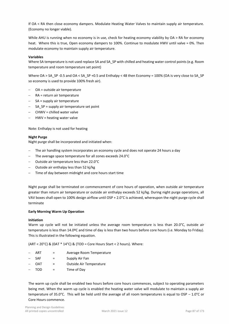
Planning and Design Guidelines All printed copies uncontrolled March 2021 issue 12 Page 87 of 173
If OA < RA then close economy dampers. Modulate Heating Water Valves to maintain supply air temperature.
(Economy no longer viable).
While AHU is running when no economy is in use, check for heating economy viability by OA > RA for economy
heat. Where this is true, Open economy dampers to 100%. Continue to modulate HWV until valve = 0%. Then
modulate economy to maintain supply air temperature.
Variables Where SA temperature is not used replace SA and SA_SP with chilled and heating water control points (e.g. Room
temperature and room temperature set point)
Where OA > SA_SP -0.5 and OA < SA_SP +0.5 and Enthalpy < 48 then Economy = 100% (OA is very close to SA_SP
so economy is used to provide 100% fresh air).
OA = outside air temperature
RA = return air temperature
SA = supply air temperature
SA_SP = supply air temperature set point
CHWV = chilled water valve
HWV = heating water valve
Note: Enthalpy is not used for heating
Night Purge Night purge shall be incorporated and initiated when:
The air handling system incorporates an economy cycle and does not operate 24 hours a day
The average space temperature for all zones exceeds 24.0°C
Outside air temperature less than 22.0°C
Outside air enthalpy less than 52 kj/kg
Time of day between midnight and core hours start time
Night purge shall be terminated on commencement of core hours of operation, when outside air temperature
greater than return air temperature or outside air enthalpy exceeds 52 kj/kg. During night purge operations, all
VAV boxes shall open to 100% design airflow until OSP + 2.0°C is achieved, whereupon the night purge cycle shall
terminate
Early Morning Warm Up Operation
Initiation Warm up cycle will not be initiated unless the average room temperature is less than 20.0°C, outside air
temperature is less than 14.0ºC and time of day is less than two hours before core hours (i.e. Monday to Friday).
This is illustrated in the following equation.
(ART < 20°C) & (0AT * 14°C) & (TOD = Core Hours Start < 2 hours). Where:
ART = Average Room Temperature
SAF = Supply Air Fan
OAT = Outside Air Temperature
TOD = Time of Day
The warm up cycle shall be enabled two hours before core hours commences, subject to operating parameters
being met. When the warm up cycle is enabled the heating water valve will modulate to maintain a supply air
temperature of 35.0°C. This will be held until the average of all room temperatures is equal to OSP – 1.0°C or
Core Hours commence.
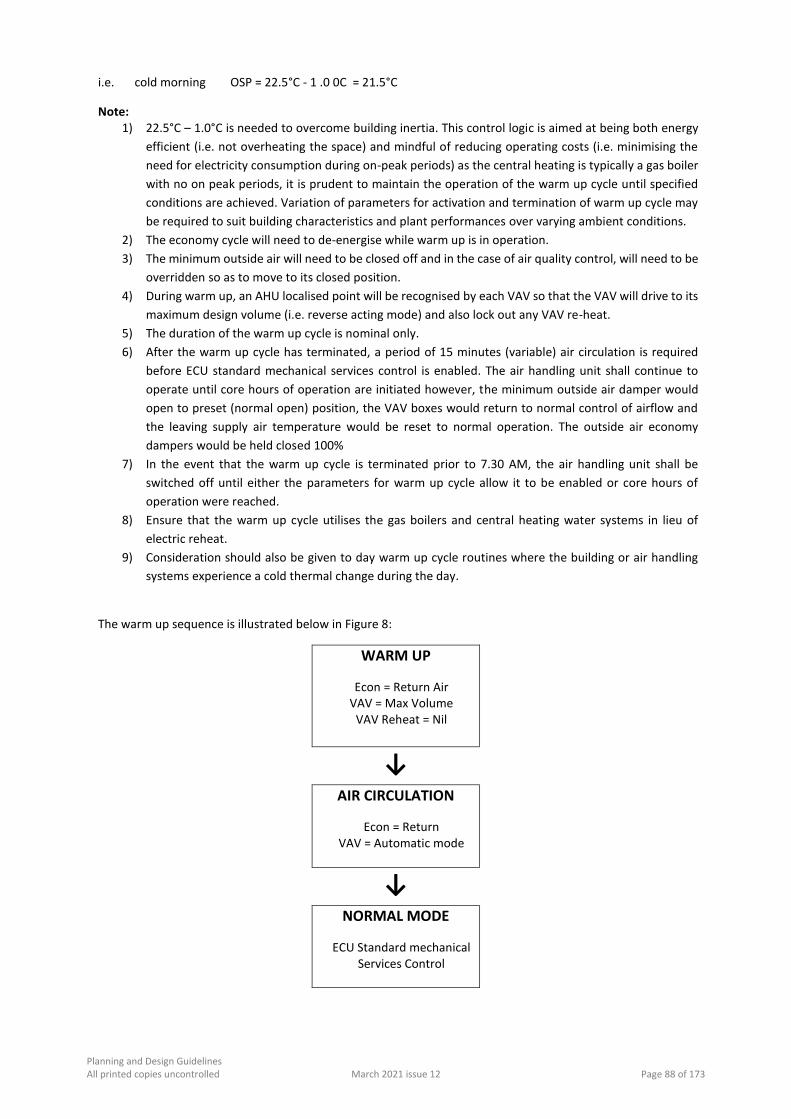
Planning and Design Guidelines All printed copies uncontrolled March 2021 issue 12 Page 88 of 173
i.e. cold morning OSP = 22.5°C - 1 .0 0C = 21.5°C
Note: 1) 22.5°C – 1.0°C is needed to overcome building inertia. This control logic is aimed at being both energy
efficient (i.e. not overheating the space) and mindful of reducing operating costs (i.e. minimising the
need for electricity consumption during on-peak periods) as the central heating is typically a gas boiler
with no on peak periods, it is prudent to maintain the operation of the warm up cycle until specified
conditions are achieved. Variation of parameters for activation and termination of warm up cycle may
be required to suit building characteristics and plant performances over varying ambient conditions.
2) The economy cycle will need to de-energise while warm up is in operation.
3) The minimum outside air will need to be closed off and in the case of air quality control, will need to be
overridden so as to move to its closed position.
4) During warm up, an AHU localised point will be recognised by each VAV so that the VAV will drive to its
maximum design volume (i.e. reverse acting mode) and also lock out any VAV re-heat.
5) The duration of the warm up cycle is nominal only.
6) After the warm up cycle has terminated, a period of 15 minutes (variable) air circulation is required
before ECU standard mechanical services control is enabled. The air handling unit shall continue to
operate until core hours of operation are initiated however, the minimum outside air damper would
open to preset (normal open) position, the VAV boxes would return to normal control of airflow and
the leaving supply air temperature would be reset to normal operation. The outside air economy
dampers would be held closed 100%
7) In the event that the warm up cycle is terminated prior to 7.30 AM, the air handling unit shall be
switched off until either the parameters for warm up cycle allow it to be enabled or core hours of
operation were reached.
8) Ensure that the warm up cycle utilises the gas boilers and central heating water systems in lieu of
electric reheat.
9) Consideration should also be given to day warm up cycle routines where the building or air handling
systems experience a cold thermal change during the day.
The warm up sequence is illustrated below in Figure 8:
WARM UP
Econ = Return Air VAV = Max Volume
VAV Reheat = Nil
↓ AIR CIRCULATION
Econ = Return VAV = Automatic mode
↓
NORMAL MODE
ECU Standard mechanical Services Control

Planning and Design Guidelines All printed copies uncontrolled March 2021 issue 12 Page 89 of 173
Day Warm Up Operation
The day warm up cycle is enabled from the following parameters:
Whilst the day time warm up cycle is enabled, the operation of the VAV boxes is then reversed such that it will
control to maximum air volume as the temperature in the room falls below the heating set point and will control
to minimum air volume as the room temperature rises above the heating set point.
WARM UP
S/A = 32.0 0C
Econ = Return Air
Min O/A = Open
VAV Airflow = Reverse
VAV Reheat = Nil
Once warm up cycle is disabled a period of 15 minutes is elapsed to allow for the air circulation. During the air
circulation cycle the supply air temperature resumes normal control, the economy cycle dampers remain in full
return air mode, the minimum outside air dampers operate and VAV boxes operate as below:
Early Morning Air
Circulation
S/A = Normal Control
Econ = Return Air
Min O/A = Open
VAV Airflow = Automatic
VAV Reheat = Nil
P/R SAF = Normal
Day Time Air Circulation
S/A = Normal Control
Econ = Return Air
Min O/A = Open
VAV Airflow = Reverse
VAV Reheat = Nil
Enabled Disabled
Average Room Temperature < OSP – 1.5 0K or
Average room temperature > OSP -1.0 0K
All AHU VAV heater positions >50% Outside core hours (0800 – 1730)
Core hours (0800 – 1730) Monday to Friday
Days of week is Monday to Friday

Planning and Design Guidelines All printed copies uncontrolled March 2021 issue 12 Page 90 of 173
AHU Static Pressure Control Air handling unit air volume will be controlled by sensing system static air pressure with the sensor located at a
distance 60% downstream of the AHU in the supply air duct index leg. The static pressure sensors locations are
to be shown on the Building Management and Control System Graphics, sensors must be located in locations that
can be accessed for future maintenance. (Variations to this will need special arrangement through ECU Buildings
and Services Branch). The static air pressure will be maintained by modulating a variable speed drive controlling
the AHU supply air fan motor speed.
The static pressure set point shall be determined in conjunction with the consultant and the commissioning
personnel such that the static pressure set point shall be measured at simulated diversified airflow for the air
distribution system.
Chilled and Heating water pressure transducers shall be provided with isolation and bypass valves, binder points
to be installed in close proximity to the transducers to allow commissioning, calibration, replacement and zeroing
of the transducer.
AHU Zone Control (Face & Bypass) Face / Bypass control achieved by taking the highest average value of any space temperature sensor on that zone
and comparing to OSP for each zone sensor to determine set point deviation
Deviation of Room Temperature against OSP / SBSP
Supply Air Temperature Cooling and Heating Reset The chilled and heating water valves will be modulated to maintain supply air temperature sensed by a supply air
temperature sensor according to the reset schedule as illustrated below. Room error referred to is obtained by
utilising the highest average of zone temperatures compared to the master set point (or room set point) in
occupied mode or the “setback mode” set point when no zones are active. If operating in the unoccupied mode
and the afterhour’s push button was activated for one or more VAV boxes or areas, then the highest average
room error would be calculated using only the activated VAV boxes or areas, with the unoccupied areas excluded
from the calculation.

Planning and Design Guidelines All printed copies uncontrolled March 2021 issue 12 Page 91 of 173
An example of the calculation of the highest average is provided as follows:
VAV No SP Actual Temp Occupied / Unoccupied
1.1 23.0 23.8 Occupied
1.2 23.3 25.0 Occupied
1.3 23.0 25.5 Unoccupied
1.4 23.0 23.7 Occupied
Calculated Average Room Error = (0.8+1.7+0.7)/3 = 1.06°C
Calculated Highest Average Room Error = (1.7+1.06)/2 = 1.38°C
A - OUTSIDE AIR TEMP
B - SUPPLY AIR RESET = 22.5 + (A + B)
Toilet Exhaust Control Toilet exhaust fan will operate during core hours plus 1 hour or whenever toilet zoned AHU is running plus one
hour. The duty / standby fans shall be step start controlled based on accumulated run hours for each fan.
Chiller Control
Interface and Reset The chiller selected by ECU will have either an electronic control panel or a full direct digital control panel.
Electronic Control Panel Control interface to Edith Cowan University’s Building Management System where an electronic control panel is
used will be as indicated below.

Planning and Design Guidelines All printed copies uncontrolled March 2021 issue 12 Page 92 of 173
Direct Digital Control Panel Control interface to ECU’s Building Management System where a direct digital control system is used will be as
indicated below.
Chilled Water Control
Chilled Water Temperature Reset The chilled water system is to be provided with setpoint reset according to the schedule below.
Chilled Water Temperature Setpoint
The staging up of the chillers on return chilled water temperature shall have the staging set points offset to match
the variation in leaving chilled water temperature setpoint such that, for example, set points of 7.0 0C / 14.0 0C
would change to 10.0 0C / 17.0 0C.
Condenser Water Reset Provide condenser water temperature reset for screw type chillers based on the following parameters:
Outside Air Temperature
Condenser Water Supply Temperature
Chilled Water Set Point

Planning and Design Guidelines All printed copies uncontrolled March 2021 issue 12 Page 93 of 173
Condenser Water Supply Temperature
Use highest of the two values above.
Screw chillers shall incorporate condenser water flow control, either via the use of throttling valves or variable
speed pump operating controlled by refrigerant differential pressure sensor, in accordance with manufacturer’s
recommendations.
Reciprocating chiller sets shall incorporate condenser water bypass in accordance with manufacturer’s
recommendations. Unless centrifugal chillers are to be utilised for lead start, these chillers would not require
condenser water throttling control. However, where a chiller plant has more than 2 chillers, and depending of the
configuration of the condenser water pipework, condenser water throttling valves or automatic regulating valves
may be necessary to limit excess condenser water flow through each vessel.
In resetting condenser water supply temperature set point, the operation and staging of the cooling tower / fans
must follow suit. Utilise free cooling across all cooling towers where possible.
Chilled Water Differential Pressure Control
Where a de-coupled chilled water system is in use, the chilled water system differential pressure will be
maintained by a variable speed drive attached to the secondary chilled water pump. The variable speed drive will
respond to variations in system pressure as read by a differential pressure transmitter. The transmitter is to be
installed at a point approximately 60% downstream of the chilled water pump in the index leg of the chilled water
system.
Where the system is not de-coupled, chilled water system differential pressure will be maintained by a bypass
valve which will respond to variations in system pressure as read by a differential pressure transmitter across the
chiller vessel. The transmitter shall measure differential pressure across the chiller to ensure minimum chilled
water flow rates are maintained while providing full flow out into the field as required.
With respect to the Joondalup campus, the operating pressure and pressure range for valves to the expansion
tank and system differential pressure have been set against the Science and Health Building No 19, which
represent the index leg of the system, including the static head exerted on the system.
For all new projects on Joondalup Campus, it is important that the engineer checks and ensures that the static
head of new buildings does not exceed that of the Science and Health Building. This will generally be achieved by
locating chilled water plant on levels below the Science and Health plant room levels. In the event the levels of
Science and Health Building plant are exceeded the engineer is to check and calculate all system pressures which
may then require some adjustments to be made to the pressure settings relevant to the thermal storage system
and expansion tank in the central plant room.
Heating Water Control
Heating Water Temperature Reset The heating water system is to be provided with setpoint reset according to the schedule in below.

Planning and Design Guidelines All printed copies uncontrolled March 2021 issue 12 Page 94 of 173
Heating Water Temperature Setpoint
Heating Water Differential Pressure Control The heating water system will have a Bypass Valve that is to maintain the boiler water temperature as illustrated
below.
Bypass Valve Position
The boiler operation shall be interlocked with a heating water flow switch, to be located on the leaving water side
of the boiler, suitably calibrated to de-ergise the boiler at minimum flow rate.
Heating Water over Pressurisation The bypass valve will be programmed to open in accordance with the schedule illustrated below, should over
pressurisation of the system occur.
Heating Water System Differential Pressure
11.33. LOAD SHEDDING
Where load shedding control sequences are utilised, they shall be incorporated where site maximum demand is
monitored. Load shedding shall have the following priorities:
Increase of chilled water supply temperature from 7.0 0C to 8.0 0C
Increase in OSP and SBSP by 1.0 0C
Isolation of operation of all electric duct heaters

Planning and Design Guidelines All printed copies uncontrolled March 2021 issue 12 Page 95 of 173
11.34. ENERGY MANAGEMENT
At preliminary design stage, subject to the extent of works to be carried out, but where new plant is proposed to
be installed, and as part of the life cycle costing of the selected plant, the consultant shall advise the ECU Project
Manager Buildings of the estimated energy consumption profiles over a 12 month period and the energy
modelling scenarios. The consultant is to identify, nominate and / or investigate all scenarios for limiting energy
consumption and greenhouse gas emissions.
The consultant shall be responsible for monitoring the operation and control of the air conditioning plant for a
period of 24 months after practical completion. This work shall form part of the consultants brief for the design
and documentation of the project. This shall include regular site visits or remote dial in to the site to observe
operation and performance of plant, make modifications to the control logic of the plant and equipment to
improve efficiency and reduce operating costs. The consultant shall instruct the contractor to make all necessary
changes at no cost to ECU, as required to achieve efficient operation of the plant. The consultant shall submit
energy consumption profiles and sign off on the operation and control of the plant and equipment every 3
months, to the approval of ECU.
The consultant shall also specify energy monitoring equipment to be provided for all forms of energy consumed
for the building. This shall be achieved via monitoring points on the digital control system. This shall include, but
not be limited to:
Ambient temperature
Chilled water consumption (entering water temperature, leaving water temperature, chilled water flow
rate)
Heating water consumption (entering water temperature, leaving water temperature, heating water flow
rate)
Gas consumption
Electricity consumption
Hot water consumption
Energy consumption / production from miscellaneous sources such as bore water, geothermal, solar hot
water, wind, photovoltaic, etc.
The consultant shall specify all necessary metering equipment necessary to develop an energy consumption
profile for each building. Where the control logic or equipment parameters have been altered, the consultant
shall ensure that the Operating and Maintenance Manuals are upgraded accordingly.
11.35. GAS METERS/BMS CONNECTION
All wiring connected to all gas meters to be installed as per Standards Association of Australia requirements for
electrical circuits in a Zone 2 environment. Protection is required to enable the circuits to be rated intrinsically
safe.
11.36. PRACTICAL COMPLETION
The consultant is encouraged to discuss the design and development of the mechanical services and the selection
of equipment with ECU’s Manager – Mechanical Services, at an early stage of the project to ensure that the
systems proposed meet with ECU approval.
Prior to issuing out to tender, the consultant shall issue to ECU’s Manager – Mechanical Services, one set of
preliminary tender drawings and specifications for review and comment.

Planning and Design Guidelines All printed copies uncontrolled March 2021 issue 12 Page 96 of 173
At practical completion, the consultant shall forward all commissioning data to ECU’s Manager – Mechanical
Service, for approval. The consultant shall also co-ordinate the defects inspection to be carried out with a
representative of the consultant, the contractor, ECU’s Project Manager and ECU’s Buildings and Services Branch.
11.37. DEFECTS WARRANTY PERIOD
The consultant and contractor shall ensure that all new plant and equipment is serviced monthly for a period of
12 months after practical completion and that maintenance service sheets for all items of equipment are reviewed
by the consultant before being forwarded to ECU for their verification.
At the end of the 12 months defects warranty period, a final inspection shall be carried out by the consultant,
contractor, ECU’s Manager, Mechanical Services and ECU representatives. A copy of all service sheets shall be
forwarded to the ECU’s Manager, Mechanical Services for their records.
After the defects warranty period, the consultant will continue monitoring the operation and performance of the
air conditioning plant and initiate improvements and modification as required up to the end of the 24-month
energy-reporting period that commences from practical completion, to the approval of ECU’s Project Manager.
ECU’s Manager, Mechanical Services shall also be advised of any changes to the operation of the plant and
equipment and the Operating & Maintenance manuals shall be upgraded accordingly, on a regular basis.

Planning and Design Guidelines All printed copies uncontrolled March 2021 issue 12 Page 97 of 173
12.0 HYDRAULIC SERVICES
12.1. PREFERRED CONTRACTORS
Contractors either tendering or working on projects at Edith Cowan University must be approved by the ECU
Project Manager and or already be an approved supplier on the University Procurement Panel.
12.2. PIPED PRESSURE SERVICES
12.2.1. GENERAL
This section of the standards outlines the minimum requirements for the following pressure services:
Cold water;
Hot water;
Natural gas;
Reverse Osmosis Water System
LP Gas (liquefied petroleum gas);
Specialist gases e.g. nitrogen, oxygen, CO², etc.;
Compressed air;
Vacuum.
In general, each riser shall be fitted with isolating valves at the bottom (or top in cases of down feeds) and each
multi storey circulating stack shall be isolated at top and bottom as appropriate. Branch lines serving an outlet
or groups of outlets shall be provided with isolating valves at the riser. To laboratories and ducts to ablution
blocks there is to be a main isolating valve. In all cases, isolating valves shall be readily accessible in ducts or valve
boxes. For water supplies, compressed air and natural gas, ring main distribution systems should be used
wherever possible and these rings should be broken down into minimum of three sections per ring by clearly
marked isolating valves in the ring system. In the case where a building is supplied by a ring main, then the main
shall be capable of being isolated on either side of the tee-off position. Isolation valves are to be clearly identified
on As Constructed drawings, for clarity it may be necessary to include a schematic layout.
All pressure pipework shall be tested to a minimum pressure of not less than 50% above Manufacturer's design
working pressure for the pipe or twice the working pressure whichever is the greater when no other relevant
Australian testing standard exists. Allow to isolate fixtures during pressure testing.
12.2.2. WATER SUPPLY
Materials Pipework. Reticulation within buildings shall be seamless tested copper tube type "B" as described in Australian
Standard AS1432.
Fittings. Shall be press fit systems and or silver soldered capillary fittings, taper/taper threaded inhibited brass
fittings, flared fittings, inhibited brass fittings or flanged connections. For connections to fixtures and fittings use
flared and/or brass barrel unions for up to and including 50mm diameters. Flanges to be used for sizes above
50mm diameters Silver solder shall contain at least 15% silver in all instances.
Valves. All valves shall be suitable for Perth water with particular regard to dezincification. Isolating valves may be
dezincification inhibited bronze gate valves or stop cocks up to and including 50mm diameter. For sizes larger
than 50mm diameter, flanged valves are to be used with flanges and valve body designed for the test pressure of
the service. Balance valves shall be globe valves. All valves to be suitable for pressure testing of both body flanges
and disc to 2100 kPa.
(Valves 80mm diameter and larger may be cast iron or steel body, bronze trimmed with DR stem.).

Planning and Design Guidelines All printed copies uncontrolled March 2021 issue 12 Page 98 of 173
Butterfly valves are acceptable for isolating purposes only and are to be stud fitted (between flange models are
not acceptable). Spindle to be stainless steel and seals to be rubber or plastic appropriate to fluid being
transported, likewise valve discs are to be stainless steel, brass, aluminium or aluminium bronze as recommended
by the valve manufacturer for fluid being transported. Ball valves are permitted.
Taps. Taps shall be of brass construction with jumper valves except where lever action valves are used and these are to
be fitted with 90° or 180° ceramic seats. Handles shall be brass or ceramic vandal proof. All standard taps, outlets
and fittings shall be of approved manufacture.
Cold Water Branch lines shall be of the following minimum sizes to domestic type outlets, unless the occupancy or use is such
that normal diversity factors are not appropriate:
Serving one outlet - 15mm min. not exceed 10m Serving three outlets - 20mm min. Serving seven outlets - 25mm min. Above seven outlets - as required.
All external hose cocks to have a minimum branch size of 20mm and where branch serves more than one hose
cock it is to be appropriately sized to suit the low diversity factor.
Direct mains water connected external wall mounted, or hot dipped galvanised steel post mounted, 20mm
polished brass hose cocks on 50mm flanged polish brass extensions for washing down shall be located around
the external surfaces of all buildings. Hose cocks shall be located approximately 600mm above ground and
positioned such that a 20 metre length of 15mm nominal bore garden hose can be fitted to the hose cocks for
the washing down of all external surfaces and windows of the building, i.e. Maximum spacing of hose cocks to be
35 to 40 metres centre to centre. All such hose cocks shall be fitted with lockable polished brass backflow
prevention hose connectors.
Minimum outlet running pressure shall be 100 kPa. Where this pressure is not available, the above minimum
pipe sizing is to be reconsidered.
Hot Water Hot water services shall be minimum of 15mm N.D. up to 10m to individual outlets, local electric units are
acceptable under some conditions where the number of outlets is small, however when electric water heaters
are used, their size and location is to be brought to University Project Manager's notice prior to the design being
completed.
In general, the hot water supply should be centralised using a number of natural gas fired Mains Pressure HWS in
parallel with an insulated flow and return system incorporating a circulating pump plus a manual change over
stand by pump.
Dead legs should be restricted to 10m maximum except to cleaners' rooms where the dead leg may be up to 20m.
Hot Water Points. In addition to areas specifically mentioned, hot water shall be provided to the following areas:
Showers Showers as directed will have the water outlets to be positioned on side walls. These outlets are not to discharge
towards the change area of the cubicle. Thermostatic temperature control mixing valves and lever action taps to
be fitted in facilities for people with disabilities and child care areas.
Staff Room Kitchen / Breakout space Hot water service shall be provided to kitchen and teas areas. Appropriately sized boiling/ chilled water units to
match staff numbers are required for tea making. A centralised hot water filtered system for staff drinking is
preferable to maintain capacity, given independent units often fail to meet demand. Independent chilled cold
water units to be provided in staff rooms and kitchens.

Planning and Design Guidelines All printed copies uncontrolled March 2021 issue 12 Page 99 of 173
Toilet Hand Basins Are not to be provided with hot water unless specifically called for in the brief. Where required they are to have
one or three tap hole mixer sets. Individual hot and cold water bib cocks are not acceptable.
Basins for Persons with Disabilities To cubicles for persons with disabilities, basins are to be provided with controlled temperature water and lever
action taps with mixer sets. Controlled temperature adjustable valves to be located above 2100mm above floor
level.
Cleaners' Sinks Are to be provided with hot water with mixed outlet and aerator (located maximum 450mm above sink).
Hot water units must be located in easily accessible locations for maintenance and access must not be
compromised by location of other services, etc.
Minimum outlet pressure shall be equivalent to cold water.
Insulation of Hot Water Lines
All hot water lines shall be insulated in material appropriate to the project and circulating loops shall be fitted
with Mechanical thermostatic control valves to maintain temperature at all points in the flow loop with a
minimum flow. The use of pre insulated copper pipe is permitted up to 15mm diameter only. Hair, felt and paper
insulation shall not be used. Sectional insulation such as Ensolex or Armaflex may be used up to the appropriate
temperature rating. For hot water distribution, ring mains shall be insulated with 25mm thick sectional fibreglass
(or the equivalent thermal rating using multiple layers of Ensolex or Armaflex) aluminium wrapped and taped.
Where exposed to view or subject to damage and in all plant rooms and ducts, pipe insulation shall be sheathed
in 0.9mm aluminium.
12.2.3. REVERSE OSMOSIS WATER SYSTEM CARL
A commercial reverse osmosis plant "Millipore" or similar approved should be used.
Reticulation shall be by means of ABS, polythene or PVC piping, the choice of reticulation material being
confirmed with the users prior to design commencing.
12.2.4. NATURAL GAS
Pipework external to buildings to be approved yellow colour coded PVC, type 2 class 100 to AS1464 or
polyethylene or similar approved plastic pipe. Isolating valves may be gate, quarter turn ball or studded butterfly.
Pipework (internal to the building) shall be seamless tested copper tube as described for water supply and sized
as required for loads but not less than 6mm diameter for up to 1m (serving individual laboratory outlets) and not
less than 15mm diameter elsewhere.
All joints shall be silver soldered as for cold water. Isolation valves within buildings shall be of the Diaphragm or
quarter turn ball valve type and each laboratory, kitchen area, plant room, etc., will be fitted with main isolating
valve conveniently located for emergency access. All rooms with gas fittings or fixtures are to be provided with
an emergency shut off button located adjacent to entry. A gas meter shall be provided to the building main
supply.
12.2.5. LPG
LPG shall be copper pipework throughout all as described for natural gas with pipe sizes adapted appropriate to
the higher calorific value of the LPG.

Planning and Design Guidelines All printed copies uncontrolled March 2021 issue 12 Page 100 of 173
12.2.6. INERT GASES
Inert gases such as nitrogen should be supplied from the bottles located within a ventilated storage space which
is easily accessible to the service road.
Cylinders shall be supported in racks and shall be manifolded with non-return valves in such a way that any
cylinder can be removed and still allow the effective operation of the remainder of the bank.
There is to be rack storage space for standby bottles.
A pressure relief valve and pressure gauge should be fitted to the low-pressure manifold, relief to discharge to
atmosphere clear of all walkways, building openings, etc.
Pipe work shall be copper and shall be silver soldered, all as described under water services. Isolation valves may
be diaphragm, quarter turn ball, and globe or needle type.
12.2.7. OXYGEN
Oxygen shall be supplied from bottles located within an easily accessible, secured, well ventilated storage space
(accessible to delivery dock). Cylinders shall be manifolded with non-return valves in such a way that any cylinder
can be removed and still allow the effective operation of the remainder of the bank.
A pressure relief valve and pressure gauge should be fitted to the low-pressure manifold, relief to discharge to
atmosphere clear of all walkways, building openings, etc.
Pipe work shall be copper and shall be silver soldered as described under cold water. Pipework to be fully
degreased prior to installation. Isolation valves may be diaphragm, quarter turn ball, and globe or needle type.
Oxygen lines shall be adequately drained and kept at least 150mm clear of pipes carrying gas.
12.2.8. COMPRESSED AIR
Compressed air shall be supplied from air compressors within the building. Compressors shall be oil free of
Broomwade manufacture (or other approved equal), liquid ring or screw to suit University service requirements.
They shall be mounted together with their motor on an integral steel base and shall be effectively isolated from
the structure. Tank mounted compressors are also acceptable.
The compressor shall be effectively silenced. Air cleaners shall be substantially mounted. Unless otherwise called
for, compressed air shall be supplied at 200 kPa at the bench outlet (confirm requirements with Client
Department).
Pipe work shall be copper and shall be silver soldered all as described for cold water and shall grade to automatic
drains with collection tundishes. Isolation valves shall be of the Diaphragm, quarter turn ball, and globe or needle
type.
An air receiver shall be provided to limit the number of starts per hour of the compressors. The receiver shall be
provided with all necessary gauges, safety valves, pressure stats and automatic drain for automatic operation.
The compressed air system shall be complete with "mains to system" air regulators. At the base of all risers and
low points in the distribution system fit water traps having automatic discharges similar to Spirax, Norgen or SMC
and complete with collection tundishes.
12.2.9. VACUUM
Vacuum shall be supplied by means of vacuum pumps within the building. Vacuum pumps shall be Nash or
Dynavac or equivalent manufacture, water ring pump capable of passing fluids from the system without damage
to the pump, fitted with bacteria filters where appropriate.

Planning and Design Guidelines All printed copies uncontrolled March 2021 issue 12 Page 101 of 173
Vacuum pumps shall be mounted together with their motor on an integral steel base mounted on an inertia base
equal to 1.5 times the weight of the vacuum pump and its ancillaries and shall be effectively isolated from the
structure. Water seals with safety interlocks shall be provided to each pump.
Pipe work shall be solvent joint Class 18 PVC pressure pipe or Type "B" copper depending on service. Plugged
tees shall be used in place of bends to allow for cleaning of piping, however at the base of all droppers and at the
low points in graded horizontal pipework fit glass removable catch pots with full pipe diameter inlet valves.
Isolating valves shall be of the Diaphragm or quarter turn ball type.
A vacuum tank shall be provided to limit the number of starts per hour of the vacuum pump(s). The tank shall be
provided with all necessary gauges, safety valves, pressure stats for automatic operation.
12.3. PIPEWORK
All pipe work to grade to liquid collection catch pots.
12.3.1. IDENTIFICATION OF PIPE WORK
All pipe work shall be identified with their names and colour codes as listed in Section 24.6.
The ground colour shall be applied over the full length of the pipeline or over a length of pipeline of not less than
450mm where adhesive labels are used. The location of identification marking shall be at intervals of not more
than 3m (not less than 1 per floor in vertical pipework) and preferably adjacent to branches, junctions, valves,
walls and control points. Such markings shall be placed so that they are easily seen from all approaches.
Service labels where applied shall be over a length of not less than 200mm at locations and intervals as specified
for ground colours.
The direction of the flow shall be indicated by an arrow adjacent to each service label. An approved adhesive
label shall be used for identification and indication of the direction of flow of pipework.
12.3.2. UNDERGROUND PIPE WORK
All underground pipework shall have a minimum of 600mm cover to topmost surface of pipe or pipes. Pipes shall
be buried in sand with a minimum of 150mm sand above, to side and below (or on a bed of crushed diorite where
base of trench is clay or rock) pipe. Pipes shall be laid in a horizontal plane and not one above each other.
Rubber ringed jointed pipe work is not permitted under buildings or within 3m of building perimeter or external
columns. All rubber ringed jointed pipework to be fitted with concrete anchor blocks in accordance with pipe
manufacturer's requirements sized to reflect test pressure.
All underground pipe work shall be identified by laying continuous PVC marker tape not less than 300mm above
the pipe. The marker tape shall be colour coded, magnetic and be printed with the identification of the pipe
contents.
All external hose cocks shall be capable of isolation for servicing either individually or in groups. Valvebox lids are
to be hot dipped galvanised hinged cast iron lid and frame set on pressed bricks and cement mortar and are to
be identified and colour coded to reflect service involved.

Planning and Design Guidelines All printed copies uncontrolled March 2021 issue 12 Page 102 of 173
12.4. PUMPS
Where required to achieve nominated pressures or flows
12.4.1. GENERAL
Pumps complete with switch and control gear should preferably be provided and installed by the Hydraulics
Services Sub Contractor to ensure correct installation and control. Pumps shall be of an approved centrifugal
either multi stage or back end pull out type. All seals shall be mechanical seals.
12.4.2. COLD WATER BOOSTER PUMPS.
A minimum of Dual cold water pumps shall be provided. One pump shall be capable of providing the flow and
pressure required. The other pump shall act as standby, however control circuits are to enable pumps to run
together during periods of concentrated load. Facilities shall exist for manual changeover for duty and standby
pumps together with individual manual test stop/start switches to all pumps. Hours run meters shall be provided
for each pump. Pressure gauges of the bourdon tube type, nominal 100mm face, with inlet union and isolating
valves for servicing shall be provided on each side of the pumps. Pumps shall be activated by a drop in system
pressure. A system pressure tank or tanks shall be provided with gauges fitted to tank input to enable checking
of pressure system.
12.4.3. HOT WATER PUMPS
Where a central system is installed, hot water circulating pumps shall be provided in the hot water loops to
minimise dead legs.
Thermostatic and timeclock control functionality should be included and connected to the BMS to enable pump
faults and temperatures to be recognised and monitored.
The hot water circulating pump shall be installed in the return water loop. Care shall be taken to ensure that
pressure in the hot water circuit is not greater than the pressure in the cold water main. Pumps shall be of the
"in line" type with totally enclosed motor. Pump casings shall be bronze with stainless steel or bronze impellers
and stainless steel shafts and mechanical seals.
Circulating pumps to be single phase 250V with one metre of flex and 3 pin GPO plug. GPOs to be mounted in
tandem with individual switching. Pumps to be individually isolated and fitted with unions so they are readily
removable for servicing.
12.5. INSPECTION AND TESTING
General Contracts shall provide to carry out all commissioning of equipment and required tests including the payment of
fees, provision of labour and test equipment. All tests shall be carried out to the applicable Australian Standard,
the requirements of any Act or Authority having jurisdiction or these Standards as set out in this specification,
whichever is the greatest.
No piping work, fixtures or equipment shall be concealed or covered by any means before they have been
pressure tested, flow tested and inspected by the Superintendent. All works shall be completely installed and
tested as required by this Section and the Code requirements and shall be leak tight before inspection of the
particular works is requested. Tests shall be repeated to the satisfaction of the authorities having jurisdiction.
All defects shall be remedied immediately and the tests reapplied to the satisfaction of the Superintendent and
the Authorities.
Planning and Design Guidelines All printed copies uncontrolled March 2021 issue 12 Page 103 of 173
At least 72 hours’ notice shall be given prior to the carrying out of tests. Where construction vehicles or similar
equipment is used on the site allowance shall be made for retesting pipelines under concrete slabs on ground
immediately prior to placing membrane and reinforcing steel or in the case of roadways, builder's tracks, etc.,
immediately prior to practical completion.
Test Pressures Gravity pipelines including soils, waste and vent piping shall be tested to maximum flood conditions for three
hours.
Water supply pipelines including Fire Mains and Services: 2.1mPa for twelve (12) hours and generally kept
charged thereafter.
Drainage Rising Mains: 1 mPa for 3 hours or 1.5 times pipe manufacturer's designed maximum operating pressure
for 3 hours, whichever is the greater pressure.
Fire Hydrants and Fire Hose Reels shall be tested for pressure of flow as required by the Fire Brigade. Such tests
to be witnessed by the Hydraulics Engineer.
Fixtures to be filled to spill level with water after installation and visually checked for leaks.
Internal downpipes to be hydrostatically tested to the maximum head possible for a minimum of 24 hours.
Pipework for gases shall be tested in accordance with the relevant code or standard or twice the working pressure
or 1.5 times the pipe manufacturers’ maximum recommended working pressure, whichever is the greater.
Gravity sewers shall be water tested as for (1) above, but with maximum hydraulic pressure plus 2m or air tested
to 50kPa (both tests being conducted for a minimum of 3 hours).
12.6. SANITARY PLUMBING
Materials Shall be U.P.V.C., cast iron, copper, stainless steel or brass subject to:
The effluent being discharged (urinals shall not discharge into copper soil drains, sewerage effluent rising
mains shall be PVC or similar approved plastic material).
Australian Standard AS 3500, Building Code of Australia and Water Corporation Bylaws.
Pipe work Shall be concealed where possible in accessible ducts and ceiling spaces.
Plumbing Ducts, Access Panels, False Ceilings etc. Architectural drawings shall be checked to ensure all sizes and clearances etc. to conform to the Authorities'
minimum requirements.
Design Design of sanitary plumbing is to be in accordance with the Water Corporation Bylaws and AS 3500.
No toilets or waste facilities shall be provided below the level of main sewer lines.
Trade Waste Generally, all waste lines from laboratories shall be U.P.V.C. unless the effluent is incompatible. Underground
drainage shall be U.P.V.C. with solvent joints. Neutralising traps shall be installed if required by regulations.
Grease traps shall be installed from all commercial kitchen areas. Trade Waste pits should be labelled with
appropriate signage prescribed by the University and easily accessible for emptying and removal of waste. All
trade waste installations shall be subject to Health Department & Water Corporation approval. Water
Corporation approval is required prior to construction commencing.

Planning and Design Guidelines All printed copies uncontrolled March 2021 issue 12 Page 104 of 173
Sewer Drainage
Design Generally, the drainage system shall be designed in accordance with the W.A. Sewerage and Water Supply
Regulations and AS 3500.
Materials Shall be U.P.V.C. pipes and fittings complete with solvent joint where minimum required cover is available.
Otherwise mechanically jointed cast iron or reinforced concrete encased vitrified clay pipe with neoprene rings
shall be used.
Pipe Sizing To minimum Authority requirements.
Filled Ground Where pipes are laid in filled ground the use of a concrete mat, crushed rock bed in lieu of pier and beams is to
be investigated and discussed with the University.
Inspection Chambers Shall be pressed clay bricks in cement mortar installed in accordance with Local Authority requirements. Gas
airtight covers to be used throughout. Medium duty covers shall be used externally except in roadway (where
heavy-duty circular covers are to be used). Light duty covers shall be used internally. Brass edged covers are to
be used where particular floor or paving finishes are to be used.
12.7. STORMWATER DRAINAGE
Design Calculations from Moores Tables N = .013.
Pipe Sizing Flooding frequency shall be decided for each project after considering the damage or inconvenience flooding
would cause.
For building drainage once in 50 years;
For site works once in 20 years.
Assessment of possible damage implication to be undertaken.
Materials Tested soil weight U.P.V.C. or V.C.P. for 100 and 150 diameters. R.C.P. for 225 diameter and over (class to be
consistent with traffic loads).
Inspection Pits Inspection pits should be constructed at major changes of direction and junctions. Precast pits with silt traps
external to buildings. Stamp S W into covers. Medium duty covers shall be used externally, and light duty covers
shall be used internally. Brass edged covers are to be used where particular floor or paving finishes are to be
used.
In paved areas, lids are to be buried but manhole covers and/or grates are to be visible at paving level and
appropriately labelled.
Fittings Generally, sumps with silt traps shall be located so as to avoid the use of pits or fittings. Overflow gutters or
sumps to be provided on drains from downpipes.

Planning and Design Guidelines All printed copies uncontrolled March 2021 issue 12 Page 105 of 173
Discharge All stormwater lines shall discharge directly into the closest existing pits, lines or soakwells. The route point of
outlet, and method of discharge is to be approved by the University. Provide a means of dispersal and water
energy reduction.
Agricultural Drains Shall be 100mm diameter (min) slotted tested UPVC pipe and fittings with lines extended to surface and fitted
with brass clear outs in finished paving. Alternatively, Nylex or similar approved strip drain can be used.
Soak wells
Shall be culvert pipes classes S, X or Y depending on traffic loads. Tops to soak well to have removable manhole
covers and 100mm diameter sighting and inspection access openings extended up to ground level.
Soak wells with slotted walls are to be wrapped with geo fabric to prevent sand from collapsing into well. Tops
and manhole covers are to suit traffic loads.
12.8. BACKFLOW PREVENTION
All mains water services to new or altered existing buildings will be fitted with Backflow Prevention Equipment in
conformity with the requirements of AS 3500 and the Water Corporation of W.A. regulations.
The basic design and installation criteria to be applied to the backflow prevention equipment are that of
“containment” generally as described below:
The individual non-potable water supply connections to buildings are to be isolated from the mains water
distribution network of the campus by installing in the buildings connection main an approved Reduced Pressure
Zone backflow prevention device (an RPZ valve). The RPZ’s are to be installed to form containment zones for the
buildings concerned.
The protection of the individual internal services of a building which is within a containment zone formed by the
fitting of an RPZ valve in the incoming supply is not necessary, except for those services supplying items of
equipment whose usages are specifically listed as requiring particular consideration under AS 3500. However, all
laboratory taps, and mixed water outlets, including those in Fume Cupboards, are to be fitted on their outlets
with high operating temperature approved DR. C.P. brass dual check valves with 316 S.S. springs. Dual check
valves are to be fixed tightly to the outlets to prevent accidental removal by staff or students and “non-potable”
water warning sign is to be mounted adjoining all such outlets.
All potable water outlets are to be supplied directly from the campus mains water distribution network, i.e. from
the upstream side of the “containment RPZ” valve.
Whilst only a single RPZ valve is to be installed in each water service between the internal distribution mains of
the campus and those of the building, pipework and isolating valves for a duplicate RPZ valve set will be installed.
Prior to Practical Completion, the contractor is to supply to the University, for stocking purposes, a second
separate tested approved stand-by RPZ valve of identical size and model to that installed. The stand-by RPZ valves
to be held by the University for use in the event of a service emergency.
To conform to AS 3500 it is necessary to fit all RPZ’s above the surrounding ground or surface level with their
discharge orifices being at least 300mm above the ground or surface. Generally the RPZ valves are to be fixed
unobtrusively on standoff brackets to the external face of the wall of the building to which they are protecting.
Labelling of all internal water service pipework shall be carried out, however, it is difficult and expensive to label
external buried pipes whose service duty changes from Potable to Non-Potable water due to the fitting of
backflow prevention devices. To overcome the difficulties and costs associated all isolating valves on all external
Non-Potable services are to be painted bright purple, whilst all new service pipework will be sleeved or wrapped

Planning and Design Guidelines All printed copies uncontrolled March 2021 issue 12 Page 106 of 173
in bright purple wrap to alert tradespersons that the service they are isolating, or connecting to, is a non-potable
service.
The existing inverted hose cocks and garden strip sprinklers around the existing or new buildings which are
connected to mains water are to be connected via RPZ valves whilst above ground wash down hose cocks
connected to mains water are to be installed as per hydraulic services briefing note for external hose cocks, no
new inverted hose cocks will be installed.
A separate allowance is to be made for the installation and fitting of water meters to all potable and non-potable
water services directly feeding buildings.
A recording and maintenance schedule following the system set out by the Water Corporation for recording the
need to test and service all testable devices and setting out the results of all testing and servicing shall be
formulated and activated.
12.9. FIXTURES
General Selection of fixtures to satisfy the following criteria:
Ease of maintenance
Availability to allow quick replacement of components.
Standardisation across the campus where possible.
Satisfy University sustainability objectives.
Where fixtures vary from University standard samples to be provided and approval to be sought from the ECU
Project Manager.
12.9.1. FIXTURES
Cisterns Half and full flush cisterns to be used. Care to be taken in the design of drainage from fittings served by low flush
cisterns to avoid frequent blockages.
Recessed cisterns located in ducts are required except in staff toilet areas but only when so approved by the
Project Manager.
Waterless Urinals Current standard utilised by the University is the Urimat product or equivalent. Ceramic material preferred given
plastic units crack and wear unreasonably quickly. Prior to specification check University service agreements for
these fixtures.
Taps The University objective is to save water by the elimination of waste. Taps to be selected for low flow.
Frequent failure of nylon operating pins to ceramic discs has been experienced with taps from one manufacturer.
Care should be taken with tap selection.
Taps are to be fitted with flow restrictors with the following general flow rates limits:
Taps general 3-5l/min is equivalent to a 5-star WELS Water Efficiency Labelling Standards) rating
Showers 6.5.0 l/min is the equivalent to a 4-star WELS (Water Efficiency Labelling Standards) rating
Flow restrictors to be hydromisers or approved equivalent.

Planning and Design Guidelines All printed copies uncontrolled March 2021 issue 12 Page 107 of 173
Chilled Water Drinking Fountains
Provision of appropriately located f Chilled Water Drinking Fountains should be made available, to enable people
to fill bottles.. Each unit is to suit people with disabilities. Refer Australian Drinking Water Guidelines. Each unit
to be fitted with an accessible isolation valve. Chilled drinking water fountains should wherever possible include
leak detection
12.10. TANKS AND HOT WATER SYSTEMS
12.10.1. TANKS
General In general, buildings other than laboratory buildings shall be supplied from mains pressure. Where water pressure
is insufficient, tanks and booster pumps shall be specified. In laboratory buildings all laboratory fittings shall be
supplied through a buffer storage tank of suitable capacity fitted with discharge pressurising pumps. All
laboratory water outlets to be labelled "non-potable". Other fittings within the laboratory building shall be fed
from the mains. All tanks shall be fitted with a strainer to the inlet.
Cold Water Cold water tanks shall be appropriate to the projects. Tanks shall be welded, 1.2mm, type 316 stainless steel or
fibreglass, circular, corrugated. Minimum tank size shall be of suitable capacity but in no case shall the stored
volume plus makeup be less than 50 litres per hour per fixture. The tank shall have a lid complete with access
manhole and internal/external ladder. Internal ladder to be in stainless steel. Tanks to be fitted with full height
transparent indicator tube.
Demineralised Water Demineralised water tanks shall have a minimum capacity of 2000 litres and shall be welded, 1.2mm, type 316
stainless steel or fibreglass circular, corrugated. Tanks shall have a lid complete with access manhole and if
necessary internal and external ladder, all in stainless steel.
Hot Water Mains pressure electric units if used shall be "Rheemglass/Zip" or equivalent. Preferably hot water to be mains
pressure natural gas pressure fired units either "Rheemglass" or mains pressure Calorifier type or equivalent.
Overflows Overflows shall be capable of discharging the full inlet water quantity. Copper safety trays shall be provided to
all tanks and hot water units and tanks shall be mounted on painted jarrah bearers within the tray.
Alarms All tanks shall be provided with high, low and extra low-level alarms. Float switches shall be of Mobrey or Flyght
manufacture or equivalent. In addition, a pressure switch shall be provided to sound an alarm should the system
pressure fail. Both tank and pressure alarms are to be connected via a Data Gathering Panel to the BMS. Pressure
pumps shall be de energised when the extra low-level alarm is actuated.
Solar Hot Water Systems Consideration shall be given to the installation of electrically boosted "solar" hot water units. In all cases the
consultant should check that the flows and temperatures available are suitable to the application.
12.10.2. ELECTRIC HOT WATER SYSTEMS
Hot water may be provided by single or multiple electric hot water units of Rheem/Zip or equivalent. Mains
Pressure glass lined type with 3.6 kW elements. Sufficient capacity and storage shall be provided to enable supply
of hot water for a minimum of four (4) hours when heating elements are shed for energy management by the
BMS. Provide electric control systems to enable load shedding via BMS of all electric elements (see Section 21.33).

Planning and Design Guidelines All printed copies uncontrolled March 2021 issue 12 Page 108 of 173
Where demand is large then gas heating is to be used.
12.11. WATER METERS
Provide water meters to master supply of all buildings. Strategy for metering and managing of consumption of
hydraulic services to be established. It is intended that all meter data to be accessed electronically to negate need
to read meters manually and integrated in to BMS system
12.12. BMS CONTROL POINTS
Allow for the following alarms, controls and monitoring points to be connected to the BMS via a DDC in the
building:
Electric Hot Water heaters for load shedding
Cold Water Tank - high, low and extra low-level alarms
Demineralised Water Tank - high and low alarms
Fire Main - low water pressure alarm
Booster Pump(s) alarms - failure
Fire Pump Alarm - failure and run
Compressed air alarms - compressor overload
Low oil pressure
Low air pressure
Vacuum alarms- overload
High vacuum
Water seal failure
Hot water circulating pumps - failure.
Water fountains
Hot and cold chilled water units

Planning and Design Guidelines All printed copies uncontrolled March 2021 issue 12 Page 109 of 173
13.0 LIFT SERVICES
13.1. PREFERRED CONTRACTORS
Contractors either tendering or working on projects at Edith Cowan University must be approved by the ECU
Project Manager and or already be an approved supplier on the University Procurement Panel.
13.2. LIFT CONTRACTS
Tenders from lift contractors are to be considered on the basis of:
Initial capital cost;
Annual maintenance costs over 25 years
Details of maintenance contracts should be submitted for evaluation with the tender and the supplied lift must
be able to be maintained by the nominated University annual maintenance contractor who may not be the
supplier of the lift. The supplied lift must not contain components/controls etc. that cannot readily be obtained
by the University’s nominated annual lift maintenance contractor. Lift contractor must supply a statement to this
effect with the Tender.
13.3. LIFT DIMENSIONS
Lift car dimensions and requirements should be checked with the University. Lifts should be suitable for persons
with disabilities access and use and at least one lift in the building should be of size to accommodate stretcher
access. Minimum clear door opening width shall be 900mm x 2000mm high (but to be in accordance with
AS1735.12-1999 relevant to access).
13.4. TYPES OF LIFT
5500 electric motor driven lift or equivalent to be installed. No hydraulic type lifts to be included in feasibility or
projects. Lifts shall have a minimum capacity of 1156kg.
Minimum 100 starts/hour with flexibility to increase starts/hour if required.
Future campus lift should include, Schindler CUBE diagnostics, or equivalent, swipe to bring to dedicated floor
voice commands to call the contractor out if stuck in lift. Sensor lighting to be provided in the lift
13.5. SECURITY
The facility shall be provided in all lifts to park the lift at the ground floor and to lock off access to and from any
floor by means of key switches keyed to the University's master keying system.
Include all necessary wiring and control logic to allow access control of lift cars.
In the event of fire alarm programme lift to go down to level 1, open doors and stop.

Planning and Design Guidelines All printed copies uncontrolled March 2021 issue 12 Page 110 of 173
13.6. FACILITIES FOR PERSONS WITH DISABILITIES
Lifts shall be designed for use by people with disabilities and shall be constructed such that operating controls,
telephone etc. are easily accessible with all to be located on the side wall.
Operating controls are to be arranged horizontally 900 above lift car floor
A handrail shall be provided internally and shall be positively fixed such that it is not subject to vandalism.
Facilities must be in accordance with the requirements of the Building Code of Australia. Provide tactile/braille
labelling of lift buttons including voice activation to floor level and on fire alarm activation.
13.7. LIFT CAR
13.7.1. INTERNAL FINISHES
Lift doors and frames shall be finished satin stainless steel for both car and landings. Internal car finish shall be
such as to minimise the possibility of damage.
Provide vandal resistant buttons and fixings.
13.7.2. CAR PROTECTION BLANKET
Each lift shall include a protective blanket for the walls of the car.
13.7.3. CAR OPERATING PANEL
The following shall be provided on the panel faceplate:
Illuminating car call buttons
Emergency stop button
Alarm button
Door open button
Door close button
"Car overloaded" illuminating indicator
Engraved load notice
Illuminating direction of travel indicators
Digital car position indicators
Exclusive service key switch
Light key switch
Fan key switch
Arrangement of controls horizontally to comply with ECU accessibility requirements.
13.7.4. SIGNAGE
Allow for installation of following signs
"No dialling required, lift handset and await response".
Identification of car by Building Number and Lift Number.
The carrying capacity of the car shall be engraved on the car operating panel faceplates.
Lift Car Number to be fitted to the inside of the car and to match ECU’s numbering system.

Planning and Design Guidelines All printed copies uncontrolled March 2021 issue 12 Page 111 of 173
13.7.5. TELEPHONE WILL STILL BE NEEDED
Telephone to be provided and will be "hot keyed" (automatically connected) to the lift service provider.
Programming will be organised by the ITSC Voice team. Handset underside to be located 900mm above car floor
level.
13.7.6. LIFT INDICATORS
Indicators are required at each floor to indicate position of lift. Provide a digital car position indication in the car.
13.7.7. CAR EXHAUST FAN
An extractor fan is required on the car enclosure complete with sound isolated supports. Fan to be a 150mm
diameter propeller fan connected to an isolating switch plug unit.
13.7.8. CAR GPO
Allow for a single phase GPO in the telephone recess of the lift car. Outlet is to have a stainless steel fascia plate
and fixing screws.
13.8. LIGHTNING SURGE DIVERTERS
Allow for installation of lightning surge diverter protection.
13.9. EMERGENCY LIGHTING
Provide an emergency light unit in accordance with the code with the power supply provided by a continuous
trickle charged battery system mounted on the roof of the car.
Emergency car lighting shall be supplied from an invertor power supply and it shall illuminate the fluorescent light
nearest the car operating panel together with the panel in the telephone cabinet door.
13.10. LIFT MACHINE-ROOM
The design shall comply with the following requirements:
The Sub-contractor shall provide a clean, completed machine with a 2 hours fire rated door. Lighting, power
points and adequate ventilation, in compliance with S.A.A. Lift Code and building regulations.
The machine-room access door, closer and notice shall comply with S.A.A. Lift Code. The machine-room
access door shall swing out.
Fire extinguishers, or a sprinkler system in compliance with S.A.A. Lift Code, shall be supplied.
Provision of a key-safe adjacent to the lift motor room entry door.
Filtered fresh air intake and exhaust shall be installed.
Where possible, finishes to walls, floor and ceiling shall be durable and painted in full gloss enamel for easy
cleaning. Where possible, the ceiling colour shall be white and walls off-white. Floors shall be properly
sealed and receive 2 coats of grey coloured paving paint.
Control and hoisting equipment shall be well lit by room lights, which shall be twin 36 watt fluorescent
reflector-type fittings with protective guards. Lighting shall be positioned so that Maintenance Technicians
are not working in their own shadow.
The control gear shall be illuminated by emergency lighting.

Planning and Design Guidelines All printed copies uncontrolled March 2021 issue 12 Page 112 of 173
13.11. KEYS
Provide a set of keys to the ECU so that in case of a fault the Lift can be Parked.
13.12. MANUAL
Provide drawings of system and Maintenance Manuals in soft copy
13.13. MAINTENANCE & WARRANTY
The complete installation is to be guaranteed for 12 calendar months from date of practical completion and is to
be fully serviced and maintained for that period.
During defects period, regular weekly servicing of equipment is required and a 24 hour call out service is to be
provided.
During defects period completion of on site log books provided under the contract are to be maintained.
13.14. IDENTIFICATION OF EQUIPMENT
All items of equipment shall be identified with engraved trefelite labels, in accordance with the University’s
Computerised Maintenance Management System QFM Coding structure. Contact the Electrical Services Branch
for details. This includes all new assets i.e. switchboards, fire panels, transformers etc.

Planning and Design Guidelines All printed copies uncontrolled March 2021 issue 12 Page 113 of 173
14.0 ELECTRICAL SERVICES
14.1. PREFERRED CONTRACTORS
Contractors either tendering or working on projects at Edith Cowan University must be approved by the ECU
Project Manager and or already be an approved supplier on the University Procurement Panel.
14.2. SUSTAINABILITY
All utility consumption is to be metered and data from meters presented in a form to allow comparison against
historical data to enable fine tuning of systems to achieve maximum efficiency. Refer mechanical services for
linking to the BMS. In addition to the BMS electrical meter data directed to the University metering system
proposal to be approved by the manager, electrical services prior to implementation. Data gathering and
reporting systems must be fully operational before practical completion.
14.3. SCOPE
This section of the Standards outlines the University's minimum requirements for electrical services including
telephone block wiring.
14.4. FLEXIBILITY OF DESIGN
The layout of light fittings, Telecom outlets and power outlets should allow flexibility such that spaces can be
subdivided into separate areas. Where island rooms exist, these shall be conduited to allow for the installation
of power and telephone outlets from the relevant sub board or F.D.P. where these are not installed in the first
instance. At least 2 x 32mm conduits shall feed each section of the skirting ducts in these areas.
Island floor outlets are not permitted as they present a trip hazard.
14.5. RCD PROTECTION
Prior to work commencing on any refurbishment works, regardless of electrical changes or alterations, RCD
protection to lighting circuits are required to be installed.
14.6. LIGHTING
14.6.1. PERFORMANCE STANDARDS
Lighting levels on the working plane shall be in accordance with the requirements of AS 1680 Series of Standards.
The defined level shall be minimum with calculated levels being no greater than plus 10%. Over illumination shall
be discouraged. Particular areas nominated for specialised requirements will be identified by the user and the
appropriate lighting levels recommended, however, at no times are these to be less than code requirements.
Options available for the control of lighting to be reviewed to ensure optimum cost effective energy management
solutions are incorporated including:
Motion detection/occupancy sensors.
Daylight/level sensors.
Time schedules.
Manual switching and grouping.
Dimming.

Planning and Design Guidelines All printed copies uncontrolled March 2021 issue 12 Page 114 of 173
LED lighting to be installed where applicable.
Such controls should be achieved by further development of existing lighting control systems on the campus.
Light fittings are to be accessible 3 metres from finished floor level so as not to necessitate the need to use
scaffolding
14.6.2. DESIGN REQUIREMENTS
1) Lighting fittings should be manufactured from Australian made components where possible and be
approved by Western Power. The fittings are preferable to be manufactured within Australia.
Downlights shall be of the LED type, to be approved by the Electrical Manager ECU. No compact fluoro’s
shall be used in any situation. If the fitting is not available in Australia then they may be sourced from
abroad provided the quality is acceptable to the University. Light fitting selection to be approved by the
University Electrical Manager, in general lamp types to conform to University standard selection.
2) For general lighting, fittings should be rated at 4000K. For specialist areas, design for the requirements
of that area and seek approval from ECU
3) All fittings should be adequately ventilated or designed to ensure excessive temperatures within the
fittings does not result. Temperature rise in the fittings should be restricted to 50°C above ambient.
4) Where recessed downlights are installed they shall have non-flammable ceiling guards installed to
prevent the insulation from encroaching on the fitting causing overheating and the opportunity of a fire
commencing. Similar or equal to Ceiling Light Guards supplied by supplier .
5) Diffusers shall be easily removable and all components shall be easily accessible. Fittings which have
to be dismantled in order to replace lamps shall not be used. Standard diffusers shall be as a minimum
K12 prismatic in general service areas, Louvered Style Diffusers in general office areas Separate
whiteboard illumination using fluorescent tube lighting or similar shall be provided. The lighting design
in Teacher areas, where multimedia presentations are accommodated is to incorporate greater
flexibility and control of lighting than normal conventional designs. Design solutions should incorporate
dimming of all lighting with flexibility to allow switching off of light fittings that adversely affect
presentations on projection screens.
6) Light fitting design and layout should satisfy the intensity requirements for open offices but should have
sufficient flexibility to enable partitioning of individual perimeter or island offices.
7) The length of fitting should suit the ceiling module.
8) External lighting of buildings shall be discussed with the University Manager and Manager, Electrical
Services. The external paths associated with a particular building project shall be illuminated as part of
that building. All external lighting shall be consistent with that of existing buildings. External lighting
control shall be through the use of BMS or building lighting control system where provided.
9) Where false ceiling exists, fittings shall be connected to the wiring loom by means of a three pin plug
and 2000mm of flexible lead. Suspend/secure cabling within building spaces of removable tile ceilings
in such a manner and spaced above ceiling to ensure cables do not interfere with removal and
reinstallation of tiles, or maintenance of in ceiling equipment. A Maximum fixing distance of no more
than 900mm apart.
10) Unless otherwise approved by University all wiring, including sheathed cables and conduiting, shall be
concealed within or by the building structure in a manner that can be replaced without damage to the
completed building finishes.
11) Where no false ceilings exist, consideration may be given to running all services exposed. Conduit runs
in this case are to be carefully worked out prior to installation.
12) Starters shall be of the electronic type equivalent to WOTAN DOES ST171 except for 20W fittings where
20W starters shall be used. Non flickering electronic starters shall be used in all areas.

Planning and Design Guidelines All printed copies uncontrolled March 2021 issue 12 Page 115 of 173
13) Downlights shall not be used for general illumination. LED downlights in conjunction with fluorescent
lighting shall be used in teaching spaces where directed to provide dimmable lighting for video
projection requirements.
14) Metal halide type fittings shall NOT be used in teaching or office areas due to the minimum of the 15
minutes strike up time and the fitting being susceptible to loss of function due to power disturbances.
14.6.3. WORKS OF ART
In the public areas of the building and in all meeting rooms within the building, ensure the spaces are able to be
used to display the University’s Art Collection. Liaison should occur at an early date in the development of the
plans with the Project Manager and Art Curator to identify “gallery” areas.
The following guidelines apply in such gallery areas:
Designated walls in gallery areas should receive no direct sunlight.
Lighting in designated gallery areas should provide an even illumination of the wall.
Where spotlights or wall washers are used, they should be dimmable LED to allow adjustment of the lighting
level between 50 lux for works on paper and 150 lux for works on canvas.
Where spotlights are used, they shall be LED and at least 2 metres (if LED can be closer) from wall.
14.6.4. EXTERNAL LIGHTING POLES & BOLLARDS
Lighting Poles & Bollards shall be “Avenue” style preferred on all campuses.
External lighting. Control of external lighting to be through the BMS. External lights consist of grounds circuits and
security circuits. Inline circuit breakers/fuses will be installed to each light pole supply. A balanced supply load
to each circuit and that grounds and security lighting are evenly distributed around external areas. Typically 50%
of each.
14.7. SWITCHING
Switches should wherever possible be located on permanent walls or columns. Switches are to be 900mm above
the finished floor level. Block switching should not be used except where special circumstances dictate.
Intentions to block switch areas should be discussed with the Manager, Electrical Services, prior to final design.
Switching and dimming in all teaching spaces shall be in accordance with requirements for Lecture Theatres. All
switch plates shall be identified with IPA studs as to circuit and switchboard of origin.
Light switches are to be rated at 15 amps (not 10 amps) and to have heavy-duty mechanism for fluorescent loads
(Clipsal 30 FLM15 or equivalent).
C-Bus Lighting Control and or Dali lighting Provide a lighting control system complete with all switching modules, dimmers, switches and other control
devices, control panels, power supplies, wiring and other equipment necessary to provide a complete and
operational installation.
C-Bus Lighting Control is the preferred lighting control system for all campuses.
The ECU Electrical Manager must be notified prior to any additions or alterations to the C-Bus System/Network.
Once the additions or alterations have been made the contractor must submit the changes to the Electrical
Manager or his Deputy, for Sign-Off, before they are saved to the Network Data Base.
Personnel carrying out works on the Clipsal C-Bus ALCS are required to have undertaken the Basic and
Intermediate C-Bus Training Course carried out by Clipsal Integrated Systems and attained an ‘Approved Installer’

Planning and Design Guidelines All printed copies uncontrolled March 2021 issue 12 Page 116 of 173
and / or ‘Point One Accredited Integrator’ qualification for the Clipsal C-Bus ALCS. A list of suitable qualified
personnel shall be submitted.
Installation, Testing and Commissioning of the Clipsal C-Bus ALCS shall be carried out in conjunction with Clipsal
Integrated Systems and an approved commissioning technician.
System The Clipsal C-Bus ALCS shall be microprocessor based and utilise Category 5E Unshielded Twisted Pair (UTP) cable
with 240V AC insulation rating as the communication medium between intelligent network nodes to control
lighting.
The system shall comprise modules with in-built microprocessors, which can be programmed via both learning
the relationships between input and output devices without the use of a personal computer or at a higher level
with a personal computer using a Microsoft Windows based application software.
All hardware shall meet the requirements for electromagnetic compatibility for certification with the CE mark.
The devices shall maintain programmed parameters during power failures with Non Volatile Random Access
Memory (NV-RAM). The control system shall remain fully functional in the event of supervisory computer shut
down or failure.
The Clipsal C-Bus ALCS shall use high speed, full duplex communications protocol. The system shall provide
constant feedback on the operational status of inputs and outputs and have the ability to interrogate the status
of specific modules.
The Clipsal C-Bus ALCS protocol shall implement the International Standards Organisation (ISO) Open Systems
Interconnection (OSI) seven-layer reference model for communication protocol.
The Clipsal C-Bus ALCS protocol shall provide transmission error checking for all information passed over the
network.
The C-Bus Automatic Lighting Management System shall incorporate the following facilities:
Time based scheduling for energy management control of lighting.
Photoelectric cell dimming control of the open plan area artificial lighting and lumen depreciation
compensation.
Occupancy sensors for energy management control of lighting.
Be an easily programmable energy management and time control, using PC and Windows XPTM based
configuration software.
Have the ability to interface with the Building Automation System at high or low level.
Automatic OFF control of lighting if required.
Automatic ON control of lighting if required.
Automatic On and OFF control of lighting using occupancy sensors.
Manual ON/OFF control of lighting at all times.
Provide an easily configurable logic engine to enable implementation of network logic functions and control
scenarios.
Provide a full range of plastic, stainless steel and glass faced switch panel options.
Provide the option for ‘Dynamically Labelled*’ switch identification using DLT technology.
Be compatible with luminaire control gear generally available.

Planning and Design Guidelines All printed copies uncontrolled March 2021 issue 12 Page 117 of 173
14.7.1. ELECTRICAL
The Clipsal C-Bus ALCS shall use an extra low voltage (less than 36V DC) bus to interconnect all control and
switching units. Cat 6A UTP cables shall be used as the wiring medium for this bus. Shielded communication cables
shall not be used due to the risk of group loop interference.
Input and output units shall be connected on the system bus in parallel.
The Clipsal C-Bus ALCS shall be powered by a two (2) wire network, superimposing data and unit DC power supply
onto one pair of data wires avoiding multiple connections of the networked devices.
Short circuit of the network power supply shall have no long-tern effect on the system once the fault is repaired.
Each unit shall have a unique serial number embedded in firmware for ongoing product traceability and
warranties, be individually programmable and be identified by a unique network address code.
The Clipsal C-Bus ALCS bus shall be electrically isolated to 3500V AC RMS for one (1) minute from the mains wiring.
14.7.2. GENERAL LIGHTING CONTROL SYSTEM FUNCTIONS
The general function of the C-bus ALCS to include but not be limited to the following general scenarios:
Offices / Administration Open Plan Areas:
Local switch On/Off, with daylight sensing
Provide intelligent programmable light level sensors, to measure the natural day light levels and according
to a predetermined lux level to intelligently monitor and dim various circuits depending on these factors.
360 degree Occupancy sensors to be located within these areas as depicted on plans and setup to
automatically turn lighting off for after hour operation.
Security, Corridor and Foyer Lighting Internal and external security lighting shall be provided to operate during normal hours of darkness. Corridor and
foyer lighting shall also be provided throughout all buildings. The lighting shall be switched in the following groups:
Group 1: External Security Lighting
Group 2: Internal Security Lighting
Group 3: Corridor/Foyer Lighting
These lighting groups shall each be contactor controlled at the local sub-board with switch control also available
in corridor/foyer for use by cleaners. A master / slave or contactor system shall be used where the master
contactor is controlled by the time switching function of the BMS. This shall apply to all external lighting.
External security lighting to be controlled in conjunction with the BMS incorporating PE Cells and time clock
function. Information relevant to types and source of external lighting shall be discussed with University Project
Manager and the Manager, Electrical Services. Designated “safe lit corridor/safe lit car park” are to be identified
by the University Project Manager and such designated areas to be totally controlled by BMS.
Each external lighting group shall have a manual override system provided at the local supply distribution board
in addition to the BMS system.
For corridor lights provided in addition to the above a local override at each entry to the corridor to allow for out
-of hours- use. (Alternatively occupancy sensors to be installed in the corridor areas for out-of-hours use.)

Planning and Design Guidelines All printed copies uncontrolled March 2021 issue 12 Page 118 of 173
Corridors
Light switch panel to be located at the entry to the corridor to allow for out-of hours use.
Occupancy sensors to be installed and programmed as a re-trigger able timer to automatically turn lights
On / Off after 60 minutes if no movement is detected.
Store Rooms/ Cleaner Rooms
Switch On/Off, with occupancy sensor, sensors to be programmed as a re-trigger able timer to automatically
switch lights On / Off after 15 minutes, if no movement is detected.
Offices
Controlled by a local switch and a PIR occupancy sensor.
Switch in the On position sets the system in Auto mode turning the lights On and enabling the occupancy
sensor, occupancy sensor to be programmed as a re-trigger able timer to switch lights Off after 20 minutes
if no movement is detected.
With the switch in the Off position this disables the occupancy sensor and the lights remain Off.
Alternately a PIR occupancy sensor only (no local switch panel) may be programmed as a re-trigger able
timer to switch lights On/Off with a 20 minutes re-trigger time delay.
Plant Rooms and Service cupboards
Local On/ Off switch
Toilets
Controlled by PIR occupancy sensor to be programmed as a re-trigger timer to turn lights On / Off after 30
minutes if no movement is detected.
Occupancy sensors to be located in both the Air lock and toilet cubicle area.
Stairs
All windowless fire escape stairs and internal stairs shall have circuits controlled only at the distribution
board.
Stairs which have sufficient natural lighting shall have lights controlled by PIR occupancy sensor to be
programmed as a re-trigger able timer to automatically turn lights On / OFF after 10 minutes if no movement
is detected. Care to be taken in locating occupancy sensors to ensure safe use of stairs
Staff / Meeting Conference / Board Rooms
Lighting to be controlled via a local light switch panel and PIR occupancy sensors.
The light switch panel will have the ability to turn the lights On/Off and dim.
Occupancy sensor to be programmed as a re-trigger able timer set to 30 minutes, when no occupancy is
detected the lights to fade Off over 30 seconds.
Dimming facility via the light switch panel with the ability to turn the lights Off adjacent to the projector
screen.
Laboratory / Teaching / Prep Areas / Foyers / Study Areas / etc
Lighting to be controlled via a local light switch panel and PIR occupancy sensors.
The light switch panel will have the ability to turn the lights On/Off and dim.
Occupancy sensor to be programmed as a re-trigger able timer set to 30 minutes to turn lights Off after 30
minutes if no movement is detected.
Dimming facility via the light switch panel with the ability to turn the lights Off adjacent to the projector
screen / white board.

Planning and Design Guidelines All printed copies uncontrolled March 2021 issue 12 Page 119 of 173
Perimeter dimming
The luminaries on the perimeter of the building shall generally be controlled such that in the event of there
being sufficient natural light from the windows, the luminaries shall be dimmed in response to the available
natural illumination by the lighting control system.
14.7.3. C-BUS CONTROL MODULES
C-Bus control modules shall be located in DB, and can be accessed where MCBs are located. Under no
circumstances will the location of controls in ceiling spaces be permitted
14.7.4. TOUCH SCREEN
The colour touch screen must be capable of controlling and monitoring the lighting control system.
A programmable Touch screen device connected to the data network shall provide Scheduling and Scene
management. Obtain an IP address from the Manager Electrical Services
Touch screen to be located in a room/ service cupboard not accessible by the general public. Location to be
approved by Manager Electrical Services
Pages to be set up to mimic inputs and outputs to individual areas as nominated.
Real time clock display and setting facilities from the touch screen.
Touch screen to provide scheduling function for internal, external and security lighting.
Schedules shall be able to be modified by the user without the use of any programming tools or devices
14.7.5. ETHERNET INTERFACE
Provided a C-Bus Ethernet interface part number 5500CN located in the communications room and patched back
to the communications cabinet. Network the system and connect to the lighting control maintenance PC at the
Joondalup campus administration building.
MAC addresses, port and switch information is to be provided to ITSC for the provisioning of VLAN’s and
assignment of static IP’s. This information will then be provided back to the Manager of Electrical Services.
14.7.6. NETWORK BRIDGE
Network bridges shall be allowed for the building as required. Limit each network to a maximum of 70 devices
and 700 meters of network cabling to allow 30% expansion for future use. If this is to be exceeded the project
must be split into multiple networks and then joined via a 5500B Network Bridge. A backbone network topology
for the project is to be submitted to Clipsal Integrated Systems for approval prior to construction.
14.7.7. RELAY AND DIMMER CONTROLLERS
The relay, dimmer and DSI gateway modules shall be housed in an approved enclosure adjacent the floor
distribution switchboard within the electrical riser. Alternatively an extension to the floor distribution
switchboard can be provided to house the modules.

Planning and Design Guidelines All printed copies uncontrolled March 2021 issue 12 Page 120 of 173
14.7.8. SYSTEM INTERFACE:
The lighting management system shall have the ability to interface to the building management system at various
levels.
Volt free contact.
BACnet IP Gateway
OPC Server software
14.7.9. NAMING CONVENTION
The C-Bus lighting control system is installed across multiple buildings. A naming convention is required to:
Ensure consistency in the naming of various projects, networks, devices and load groups in each building.
Provide a mechanism to easily identify where the device is located and what area it controls.
Minimise the use of cryptic acronyms wherever possible.
General Format
General Format for naming of a point shall be:
Project>Network>Application>Group Address
Project Describes the name of the building and site (up to 8 characters)
Network Describes the vertical or horizontal location as a floor level.
Application Describes the control system application
Group Address Describes the controlled load type and location. Include ipa\ circuit# if a relay
Example:
Project Network Application Group Address
Building 21 Level 2 East Lighting Rm 2.01 front W1
The concept is that a programmer or maintenance staff person is able to identify the group address or tags with
minimal reference to drawings or documentation.
Project identifier can only have 8 character; all other identifiers have up to 32 characters.
Device Identification All units on a C-Bus network have a unique identity code called a unit address, this identifies a specific device
connected to the C-Bus network. A reserved unit address approach should be taken when designing the project.
Following format shall be followed:
Unit Address Unique code that identifies each unit on a single network.
Part Name Tag to identify unit. Restricted to 8 characters.
Tag Name Tag to identify unit, up to 32 characters.

Planning and Design Guidelines All printed copies uncontrolled March 2021 issue 12 Page 121 of 173
Example:
Unit address Part Name Tag Name
052 Rm 508 Rm 508 switch 1
Note:
Reserved address approach should be used where the outputs start an unit address 001 and input devices
from unit address 020 and above.
Unit address 255 is reserved as a default for new units, no C-Bus device with this address should be left
connected to the network once commissioning and handover has been completed.
Abbreviations should only be used where the C-Bus system cannot accommodate the full text description.
14.7.10. DOCUMENTATION
The Installing Contractor shall provide a complete set of 'as installed' drawings and an end user instruction booklet
Label all C-Bus distribution board schedules internally include C-Bus unit number on module.
Include secure copies of electronic databases of all programmed devices including C-Bus Tag database, C-Touch
Project file xml, PAC xml file or any other files needed.
14.7.11. WARRANTY
The Clipsal C-Bus will carry a two-year warranty; the installer to provide proof of installed dates and is subject to
manufactures conditions of Warranty.
14.8. POWER
14.8.1. SOCKET OUTLETS
Unless specific requirements are detailed, allow two double Socket outlets per workstation or 10m2 of net
useable space. All socket outlets shall be identified by means of circuit identification I.P.A. red, white and blue
studs as to the circuit on which they are installed and the switchboard of origin. In the case of the Clipsal 2000
range socket outlets the IPA shall be installed under grid plates and an adhesive label to the face between the
socket outlets.
All three phase outlets shall have 5 round pins.
Emergency power isolation is required for all power outlets in each laboratory, machine room that are considered
to be hazardous areas but such rooms do not include computer teaching rooms where general teaching in
computing is carried out, and is to be located at the lecturer's bench or in locations approved by the University
Project Manager and the Manager, Electrical Services. All services emergency stop control for an area shall be
grouped together for easy, convenient access.
All socket outlets (1 phase and 3 phase) shall be protected by devices incorporating 30mA RCD Protection
(Residual Current Device).
All Socket outlets protected by RCD’s shall be engraved in 5mm high green filled lettering “RCD PROTECTED”.
Unprotected power may only be provided when written permission has been given by the Maintenance Manager,
Electrical.
All Socket outlets not protected by RCD’s shall be engraved in 5mm high red filled lettering “Not RCD Protected”
with the name of device under, i.e. “NOT RCD PROTECTED BOILING WATER UNIT ONLY”.

Planning and Design Guidelines All printed copies uncontrolled March 2021 issue 12 Page 122 of 173
Engraving of removable surrounds is not acceptable.
Provide dedicated Socket outlets for cleaners (engraved accordingly) at appropriate locations throughout the
building, catering for vacuum cleaners, etc. These outlets are to be installed 600mm above floor level.
All socket outlets are to be switch operated.
All lectern GPO’s require soft start.
14.8.2. SWITCH BOARDS AND SUB BOARDS
Main Switchboard. Regardless of the initial requirements, the main switchboard shall be designed to Form 3B and be able to
withstand the maximum prospective fault level for the maximum design capacity of the substation. All
switchboards will be fitted with smoke detection. The main switchboard shall be of type tested construction,
floor mounted, free standing compartment cubicle type construction ("dead front" type and fitted with circuit
breakers or switch fuse units to control outgoing circuits).
The unimpeded space around a Main Switchboard shall not be less than 1.2 Metres where the panels are
removable either with or without tools to permit the tradesperson enough exit space.
The switchboard is required to be approved prior to manufacture by the University Manager, Electrical Services.
All such switchboards are to be of steel construction.
Building main switchboard shall incorporate Shunt Surge Diversion to the incoming supply. In addition inline
surge reduction filtering shall be provided to “clean power” supply to boards serving Teaching and Laboratory
areas as directed by University.
All switchboards shall be provided with an individual feed to a 10A Socket Outlets incorporated into the
switchboard or in an easily accessible location on the wall within the cupboard, for test equipment use.
Provision shall be made to extend the main busbar systems in either direction. At least 25% spare space shall be
provided as an absolute minimum. Main switchboard shall have capacity for additional switchgear and sub mains
for future expansion. Mains cables shall be sized accordingly to take account of the full expansion potential of
the board.
All Switchboards shall have Isobars fitted.
Generator Supply Where specified a Generator Supply inlet socket shall be fitted to the outside of the Building Main Switchboard,
Sub Board or Switchroom or as specified by the ECU Electrical Manager. An electrically interlocked changeover
switch shall be installed on the switchboard and labelled accordingly. Key access to switchboards is to comply
with the University's Keying System.
The main switchboard shall be designed in accordance with AS 1136 "Switchgear and Control Gear Assemblies for
Voltage up to 1000V AC".
Following full load being applied to board, typically mid-way through the defects liability period, condition
monitoring of switchboards to be carried out using thermal imaging. Report on thermal imaging to be included in
electrical manual.
Sub Distribution boards, lighting and power supply. Sub-boards shall be of steel construction and arranged for floor or wall mounting unless circumstances dictate
otherwise. At least 30% spare capacity shall be provided on all sub-boards. Sub mains cables shall be sized to
take account of the full expansion potential of the board. Escutcheons shall not be interlocked with switches,
isolators or circuit breakers.
Key access to switchboards is to comply with the University's Keying System.

Planning and Design Guidelines All printed copies uncontrolled March 2021 issue 12 Page 123 of 173
Lighting, power and 3 phase circuits shall have clearly defined separate areas on the sub board with each having
its own isolator in addition to the distribution board main switch. A separate mechanical services switchboard
(MSSB) or separate section on the board shall be provided for air conditioning feeds. Boards servicing Teaching
and Laboratory areas may also require separate “clean power” chassis section and isolator.
Vermin Protection. All switchboards and sub boards shall be designed to be vermin proof.
Fuse Cartridges. All fuses shall be HRC cartridge type conforming to AS2005 and AS3135. A minimum of six (6) spare cartridges
for each rating shall be supplied at each switchboard position. Spare fuse cartridges shall be mounted on a
suitable rack, easily accessible without removing escutcheon plates. At the main switchboard, in switch rooms or
substations, spare fuses shall be located in a wall mounted enclosure. At distribution boards, cupboards, the
fuses shall be mounted internally on rear face of door. In special circumstances DIN fuses may be acceptable up
to 32 amps.
Sub Metering. Metering shall be provided by microprocessor based networked monitoring devices providing complete electrical
metering and indication Schneider approved metering with pulse output capabilities.
Master meters shall be provided in each building main switchboard to register building consumption and
consumption for each of the main building services emanating from the board including, but not limited to Air
conditioning and Mechanical Services, Hydraulics and Hot Water with slave meters for submains to selected
distribution boards. The main meter for the building provide Pulse kWhrs output to the BMS.
Push Buttons. Shall be of the shrouded type.
KW Transducers. Shall not be used without prior approval from the Manager, Electrical Services.
Indicating Lights. Shall be of the integrated LED lamp type with a minimum life of 100,000hrs .
Meters. All meters should be digital
Metering test link. Shall be provided for all current transformer sensing metering complete with voltage isolating
links and current shorting links.
Labelling. Each and every control, switch etc. on main switch-boards, sub-boards etc. shall be clearly labelled. All labels
shall be engraved traffolyte, and attached to the switchboard by means of non self tapping type screws.
All ECU assets to have asset list identification labels attached. This will be carried out under the project and
installed by the contractors.
Circuit Schedules. Shall be typed and be provided at all switchboard positions. The information contained on the schedules shall
consist of circuit breaker identification number, phase colour corresponding with type and location of each circuit.
This information shall incorporate room number and whether it serves power, lighting, mechanical services, etc.
The switchboard schedule to indicate where supply is fed from, cable type and size to be laminated and fixed to
inside of switchboard door and shall also contain the switchboard sub-main size and point of origin.
Colour. All switchboards shall be colour orange X15 (AS2700 1996).

Planning and Design Guidelines All printed copies uncontrolled March 2021 issue 12 Page 124 of 173
Circuit Breakers. To final subcircuits shall be Schenider or equvilent type miniature circuit breakers and shall have individual RCD
protection for all power circuits and lighting circuits. Other circuit breaker types may be submitted to the
University for approval.
Discrimination. Prior to selection of switchgear a supplier, the switchboard manufacturer must ensure discrimination can be
achieved as follows.
Co-ordinate the protection equipment on all main and distribution switchboards such that in the event of any
condition of over-current or short circuit occurring at the load side of terminals of any submain protective device
or final subcircuit equipment isolator/connection device:
Sub-mains protection effectively discriminates.
All lighting circuits continue to operate apart from any lighting which is supplied by the faulty circuit.
Short circuit calculations shall be for all faults up to and equal to the prospective fault current at each distribution
switchboard.
Certify compliance with the above in writing to the Principal, including fault and discrimination calculations for
switchgear used prior to submission of switchboard shop drawings for examination.
Submission of equipment list and manufacturer’s discrimination and enhanced selectivity charts are acceptable
in lieu of individual calculations, where these are available.
All Neutrals, Earths and Active Cables.
Shall be number ferruled to correspond to the circuit breaker number. All circuit breakers shall be numbered
consecutively on the escutcheon plate and on the circuit breaker mounting bracket for ease of identification once
the escutcheon plate has been removed.
All active cables entering circuit breakers shall be via cable lugs. All control wiring shall have number ferruled
with numbers as indicated on as constructed drawings.
Neutral bars shall have the same number of terminations as there are circuit breakers and holes for main neutral
and MEN connection. Earth bars to have terminations equal to the number of circuit breaker positions. Blue
point connections shall not be permitted within switchboards and sub boards without prior approval from the
Manager, Electrical Services. System of earthing shall be MEN system.
Standard Equipment. For all switchboards and sub boards for light, power, air conditioning or other building services shall be as follows:
Alarm Relays Releco MR C 11 pin base.
Time Relays Releco MR C 11 pin base.
Auto/Off/Manual Switches Kraus and Naimer.
Active Links Blue Point or Busbar System.
A sample of the contactors shall be submitted for University approval prior to their installation in switchboards.
Inspection and Testing The University reserves the right to inspect during the course of construction. The sequence of inspections is as
follows:
1) Approval of switchboard drawings prior to commencing manufacture.
2) Factory inspection when the switchboard is assembled prior to painting.

Planning and Design Guidelines All printed copies uncontrolled March 2021 issue 12 Page 125 of 173
3) Factory inspection after ductor, primary/secondary current injection and hi-pot tests have been carried
out prior to leaving the factory.
4) During the warranty period, the highest load time frame to be agreed with the university for a
thermograhic and Power quality analyse be carried out and a written report be submitted to Building
and Services.
14.8.3. QUALITY OF POWER SUPPLY
At the point of attachment to any new building, the Power Factor shall be less than 0.85 during ON PEAK hours
at normal running load. If the Power factor is not less than 0.9 then Automatic Power factor correction equipment
shall be installed at no cost to the University.
The Currents across the three phases shall be balanced within plus or minus 10% of each other.
The quality of the power at the point of supply to a new building shall conform to AS2279 and Western Power
Technical Requirements. A power quality audit shall be carried out prior to tenant’s occupation and after during
the peak load period to verify it conforms to the standards specified. If the supply is non-conforming due to
tenants equipment then the University shall cover the cost of filtration but if the source the distortions are for
example from a Variable speed drive on the Air conditioning plant then the contractors will be responsible to
cover the cost of installing Filtration or rectifying. The reports of Quality Audit are to be provided for inclusion in
the Electrical Maintenance Manual for the Building.
14.8.4. SUB MAINS.
Underground sub mains shall be in PVC conduits, via cable pits (Gatic lid and brick construction trafficable type
where in paths). Where fibro cement or similar pits are used they shall be installed with 100x100mm concrete
collar to strengthen lid support lip. Provide adequate spare conduits for future use. Pits shall be drilled for conduit
access and gaps around conduits filled to approval.
14.8.5. EARTHING
Provide all Earth Testing data of the total installation to indicate compliance with regulations.
14.9. GENERAL WIRING
Power and 240V control cable shall not be less than 2.5mm2 stranded copper, 240 volt control cable shall be not
less than 1.5mm2 stranded copper conductors. Lighting circuits shall be wired using not less than 1.5mm2
stranded copper conductors. Colour coding shall be in accordance with AS 3000 part 3.2. Control wiring shall be
white with a minimum size of 1.5mm2 stranded copper cable. Single core copper cables shall not be used.
Colour differentiate power from light cables. Black TPS for power and white for light.
Install and conceal all wiring, including sheathed cable, within or by the building structure in a manner that can
be easily replaced without damage to the completed building finishes.
Suspend/secure cabling within ceiling spaces of removable tile ceilings in such a manner and spaced above ceiling
to ensure cables do not interfere with the removal and reinstallation of tiles, or the maintenance of in ceiling
equipment.
Loop cables from point to point with joints and connections only at switches or outlets.
Seal cabling passing through a roof with a mechanical screw-up gland and apply an approved non hardening UV
resistant sealant.
Do not install cables in any area until all construction work which is likely to damage cable is completed.

Planning and Design Guidelines All printed copies uncontrolled March 2021 issue 12 Page 126 of 173
Group and install all cabling in straight runs parallel with line of building. Refer to AS3000 Wiring Rules regarding
derating factors for cables. Cable sizes specified have not been derated for grouping of multiple circuits unless
otherwise noted. Where derating is necessary due to installation method/grouping, increase cable sizes as
specified in AS3008.1.
Cable entries to switchboards or equipment shall be via gland plates or through panels shall be made using
circular, orange sheathed, cable and suitable compression glands. Double insulated flat cable may be used if
entering through ducts or conduits.
All metal Cable Trays, Ducting, Trunking, Cable Enclosures and conduits shall be bonded to earth, back to the
nearest switchboard.
Portable electrical equipment and heaters used in hazardous areas to comply with AS3000 and AS1076.
Cable trays, conduits and conduit saddles shall have the following colour coding throughout the entire installation:
Orange for power, lighting and 240V controls.
Grey for Data or Extra Low Voltage or Low Voltage Controls.
Blue for all data cables.
Conduit saddles shall be of type to ensure conduits are installed flush with wall/ceiling surface. Ducts and cable
trays shall be fully galvanised where exposed to the weather and colour banded to the above schedule every 3
metres (to all locations). All cable trays shall have 15% spare carrying capacity.
14.10. EMERGENCY LIGHTING
Emergency lighting shall be provided in accordance with the requirements of the Building Code of Australia and
the Australian Standards.
Careful selection of emergency lighting shall be made so that the lighting meets the University’s statutory
obligation in a discrete way, particular attention to this issue must be made when emergency lighting may impact
on architecturally splendid areas such as building entry points or architectural areas of importance.
Where existing Nexus monitored emergency lighting systems exist those systems shall be added to and extended
as necessary. All systems shall be fully tested and commissioned to the supplier’s and ECU’s satisfaction.
All new buildings shall have Nexus monitored emergency lighting systems installed to match the existing systems
on ECU campus. Any such new system shall be networked back to the head end PC on Joondalup campus as part
of the project.
Emergency exit lights shall be of a LED type. Battery types shall be of the highest quality and designed to provide
the longest possible life for the battery. Where access to emergency lighting is at normal ceiling height battery
pack shall be mounted local to each fitting. Where situations with high ceilings or difficult to access areas exist
other options may be considered in consultation with ECU. Surface mount type fittings shall not be used.
As constructed data for emergency lighting systems shall include fully documented drawings including type and
locations of fittings. Where computerised systems have been provided emergency lighting database reference
information shall also be contained on the drawings.
Refer to AS 2293 "Emergency Evacuation Lighting in Buildings".
Emergency lights shall only be decommissioned with ECU approval prior to any work being carried. (We are have
a lot of faults on the Nexus system, due to contractors disconnecting Lights and not recommissioning them)

Planning and Design Guidelines All printed copies uncontrolled March 2021 issue 12 Page 127 of 173
14.11. EXIT AND STAIR LIGHTING
Exit and stair lighting shall be in accordance with the requirements of the Fire Safety Act. Exit and stair lighting in
enclosed stairs shall be designed to be "ON" at all times. Switching therefore shall be provided only at the circuit-
breaker. In non-enclosed stairs, or stairs where natural light is sufficient for day time use, stair lighting shall be
switched by the external lighting program of the BMS and energy management lighting control system when
applicable. Emergency lighting to these areas shall be installed. Provide exit and stairway signs to comply with
relevant codes. Emergency lighting system shall be monitored by the emergency lighting control systems. All
light fittings to be installed no more than 3 metres finished floor level.
14.12. LIGHTNING PROTECTION
Lightning protection shall be provided, if required, to all buildings in accordance with AS 1768 1991. Lighting
protection is required on all Joondalup Campus Buildings due to the high “strike” incidence on the campus.
14.13. ELECTRIC FANS AND FAN HEATERS
Only allowed for use for medical reasons
14.14. TOILETS
Allow for one socket outlet adjacent to the mirror in toilet areas. No socket outlets for general use shall be
installed within the restricted zones as defined by AS 3000.
Supply, install and commission duress alarms in the disabled toilets. The alarm system to consist of an alarm
button, a sign in the toilet and two flashing/buzzing lights (one just outside the toilet and another in a general
area) - refer to photo 1, 2 and 3 below. A parallel signal from the button to be wired back to the security system
to be included in the access control monitoring system relayed back to the Security Control Centre.
Photo 1 photo 2 photo 3

Planning and Design Guidelines All printed copies uncontrolled March 2021 issue 12 Page 128 of 173
14.15. TEA ROOMS
Allow for sufficient power for briefed equipment including general power outlets for general use.
3 phase power to be provided for water heater where specified.
14.16. GAS METERS
All wiring connected to all gas meters to be installed as per Standards Association of Australia requirements for
electrical circuits in a Zone 2 environment protection is required to enable the circuits to be rated as intrinsically
safe.
14.17. DISTRIBUTION SYSTEM
Distribution of power and telephone/data wiring may be by means of a two channel perimeter aluminium skirting
of colour as directed by the consultant architect.
In large open areas, in floor, two channel duct with floor boxes and sealed cover plates should be considered as
well as service poles. Where island rooms exist, these shall be conduited to allow for the installation of power
and telephone outlets from the relevant sub board or F.D.P. where these are not installed in the first instance.
Floor outlets for power and telephone outlets shall be of Clipsal manufacture or equal, however floor outlets are
not recommended as they present a "trip" hazard.
All ducts shall have a minimum of 2 x 32mm feeds from the sub board to each section of the duct.
14.18. CLOCK SYSTEM
Clocks only used in Exams
14.19. ELECTRIC WATER HEATERS AND CIRCULATING PUMP
Water heaters and circulating pump shall be controlled through the BMS with over-riding control at the
distribution board supplying the circuits.
14.20. UNDERGROUND SERVICES AND PITS
All underground services shall be installed in accordance with the requirements of AS 3000 shall be colour coded
as follows:
Gas Services = yellow painted lid
Fire = red
Water = green
Electrical = orange
and shall be laid in sand with 75mm below and 150mm above and to sides and shall be identified by laying an
approved continuous PVC marker tape 300mm min. above the conduits.
Only selected backfill shall be used and shall be compacted in layers not exceeding 200mm to a density of 90%.
Compaction Standard achieving a standard penetrometer reading of 8 min blows per 300mm. The minimum cover

Planning and Design Guidelines All printed copies uncontrolled March 2021 issue 12 Page 129 of 173
shall be in accordance with AS 3000 and in any case, not less than 600 mm to top of conduit. Concrete cover to
conduits to a lesser depth will be allowed only after written approval from the Manager, Electrical Services.
Minimum size of underground conduit shall be 32mm. Underground cable shall be PVC/PVC cable, not less than
2.5mm2.
Underground cable joints are not acceptable on sub mains. Maximum distance between pits on underground
cable runs shall be 60m.
All underground pits shall have their lids marked indicating the service installed and pits shall be adequately
drained.
All cable passing through pit shall be permanently tagged to approval indicating point of origin and termination.
Provide clearance between services as required by relevant Acts, Regulations.
All underground electrical services are to be laid in straight, direct lines.
All external cable Pits are to be trafficable.
14.21. SUBSTATIONS
Where required, provide new substation, new boundary switch room or modify existing substations as required.
Electrical feed to be a ring main type system to new buildings.
Allow for new switchboards, transformers, switchgear as required. Substations to be 2 hour fire rated and comply
with requirements of Western Power and AS 3000.
Transformer size to be determined and to be part of the contract.
Provide spare FCUs for future use.
All high voltage switching shall be performed by Western Power trained staff having the required certification.
No work shall commence on high voltage network without an Access Permit in place and signed by all parties who
will be carrying out the works.
Where any high voltage cable is to be cut, altered or moved, the Contractor shall arrange with the Consultant and
Manager, Electrical Services to test and mark the cable to ensure that it is the correct cable and that it is not “live”
before work commences.
Once the cable is proved DEAD it shall be “Spiked” with the approved equipment before any work is commenced.
All work shall be checked and tested as appropriate before the switching is carried out. Final approval for
energising of a new substation lies with the supply authority. No switching shall be carried out without their
approval.
The Contractor shall meet all costs associated with switching and commissioning.
14.22. REGULATORY AUTHORITY NOTICES
For all electrical installation work Electrical contractor shall submit a Minor Works or a Preliminary and
Completion Notice to the supply authority and at the same time a copy to the Manager, Electrical Services.
Contractors shall also complete an entry in the campus site electrical record book detailing:
the location and nature of works;
the number of the notice;

Planning and Design Guidelines All printed copies uncontrolled March 2021 issue 12 Page 130 of 173
Contractor’s name, name of person carrying out work and their license number.
Any Electrical Work and or equipment that does not conform to these Planning and Design Guidelines shall be
removed and reinstated to the appropriate standard, at the Contractors expense.
14.23. AUTO DOORS
Operator Operators for auto doors to be Dorma EL301 or similar approved and be complete with:-
Separate entry exit sensors.
Electric constant rated stall proof capacitor start squirrel cage motor.
Battery back-up for a minimum 300 operations.
Photo-electric cells across doorway.
Controls to be interfaced with the buildings Fire Alarm and Security access control systems.
Switches and push buttons shall be mounted 900mm above finished floor level.
Operation Normal Hours
The doors shall allow free access and exit via local movement sensors.
Close after time delay
Fire Alarm condition – Doors operate as normal.
After Hours
The doors shall be controlled via the Security access system. Only a valid card holder is permitted.
Exit via Exit push button or in secure areas via a card reader with a back-up break glass. Close after time
delay.
Fire Alarm condition – Doors open and remain open until the fire alarm is reset.
Request to Exit Button The request to Exit (EX) push button shall be momentary bell press switch. The push button shall be a Clipsal
prestige series P30MBP or equivalent in the same orientation to other fittings.
The push button shall be engraved in red “PUSH TO EXIT in capital letters a minimum of 8mm in height and
centrally located above the button. All “End of Line Resistors” shall be located on the rear of each plate and
securely fixed.
Key Switch Dorma key switch is SK. Allow to replace lock barrel with ECU Lockwood standard barrel 245K.

Planning and Design Guidelines All printed copies uncontrolled March 2021 issue 12 Page 131 of 173
15.0 COMMUNICATIONS
15.1. GENERALLY
Contractors Any work carried out on the University Communications cabling and systems can only be done by contractors on
the current ECU Procurement Panel approved list of preferred contractors.
ACA Specifications, Approval and Australian Standards This work shall be carried out strictly in accordance with the current ACA specifications and appropriate Australian
Standards by an appropriately registered cabling contractor. The cabling installation shall comply with the current
issue of AS11801, “Generic Cabling for Customer Premises”, unless this brief specifies otherwise.
Equipment to be provided The cabling contractor to supply and install data/telephone cabling system complete with all equipment racks
(unless directed otherwise), patch panels, terminal blocks, connectors, cables, patch leads, records, jumpers,
accessories and consumables. All projects shall be ACA approved and clearly marked as such. Cabling Contractor
to install conduits and wiring access for facility cabling. All cable trays and supports for block wiring shall be
supplied and installed by contractor.
Telephone/Data Backbone Cabling Telephone and data backbone cabling shall be included in the contract.
Telephone Handsets and Final Connection Telephone handsets will be supplied and installed by the University. Final connection of the telephone i.e.
jumpering on the IDF/MDF and connection of the patch lead in the Communications Cupboard/Room shall be
carried out by the University. For New Building the IDF/MDF jumpering will need to be completed by the Electrical
or Communications contractor.
Earthing Provide a complete earthing system to ACA approval for telephone and data distribution system, including
connection to the main earth.
Locks and Handles All locks on Communications Rooms and Cupboards shall use an "AS2" cylinder in the University's standard lock
series unless otherwise specified. Doors shall only be able to be opened with a key and be self locking on closing,
but shall have a handle on the inside or be arranged to prevent persons being trapped. Doors shall open outwards
and shall have a fixed handle on the outside.
15.2. CABLING PROVISIONS
15.2.1. GENERAL
Provide for communications cable distribution using either two or three channel skirting duct mounted either at
skirting level or bench height depending on application. In staff offices the ducting is to be at skirting level.

Planning and Design Guidelines All printed copies uncontrolled March 2021 issue 12 Page 132 of 173
Ensure duct has adequate conduit entries for cabling requirements.
Provide a detailed block diagram for each building specifying:
Cable type
Patch Panel Number
Wall Outlet Number
Outlet type
Origin
Destination
Termination connection points/Number off
Provide lightning surge diverters to data/telecommunications lines.
All cabling to be as per ACA TS 102-1998 (Australian Communications Authority Technical Standard Customer
Equipment and Cabling) and the other applicable Australian Standards. All cabling contractors shall be registered
with the ACA as accredited registrar.
15.2.2. SITE CABLING
Special Services Cable Provide special services cabling in conduits between the building's main data frame and the Special Services
Frame in each building. Terminate on Krone frames at each end.
Fibre Optic Cable Optical fibre cabling shall meet the requirements of AS/ACIF S008 and shall meet or exceed the performance
requirement of AS/NZS11801.1 Optical fibre cables shall terminate at fibre patch panels located. Each cable shall
be continuous from one patch panel to the destination patch panel without intermediate joins or connections.
The cable strength member shall be securely fastened at the termination enclosure. Leave a five (5) metre loop
of cable at each end for future connection by the University.
Where fibre optic cables pass through underground cable pits provide cable loop ( 300 dia) and cable tie to
prevent loop uncoiling. Indelibly label all underground cables within pits clearly notating where the cable
originates, type of cable and where it terminates.
Cabling Requirements All cabling shall be installed in full accordance with the manufacturer’s recommendations.
Cables shall be installed with due skill and care such that:
maximum permitted hauling tension is not exceeded
minimum bending radius of the cable is not exceeded
maximum permitted crush rating is not exceeded
the cable is protected from damage.
Cable bundles shall not obstruct the installation and removal of equipment within equipment enclosures.
Wiring frames shall be wired such that jumper connect wires follow clear paths between sections and are not
obstructing patch fields, and that lengths of jumper connect wires are minimised.
Equipment and patch cables shall be laid out such that patch cords follow clear paths and do not obstruct patch
fields.

Planning and Design Guidelines All printed copies uncontrolled March 2021 issue 12 Page 133 of 173
All copper cabling entering a building shall be provided with line protector surge arrestor units at both MDF and
IDF ends, Critec SLP 10-K4 or equal approved to TS009.
15.3. DETAILED REQUIREMENTS
15.3.1. SERVER ROOM
Server rooms are critical infrastructure. In general the following to be considered:
Heat loads of equipment to be accurately determined.
Plan for heat dissipation must be based on a clear understanding of air flow.
Power supply to be uninterruptible.
The Air-conditioning Systems to be based on N+1 Duty/Standby back up, the Duty to be a Chilled Water
System and the Standby back up to be a Direct Expansion System.
Facility to be fire protected and include a fire suppression system.
Facility to be secure and have access control.
A risk assessment to be prepared and signed off by the ECU IT Technical Services Manager
Access for delivery and installation of equipment.
15.3.2. COMMUNICATIONS ROOM
General Each building shall have at least one Communications Room, preferably centrally located on the ground floor, to
securely house equipment to provide communications and computing services for general use in the building.
The Communications Room is the hub for the communications wiring for the building and shall be directly
connected to the underground service duct network.
The room shall be sized to accommodate a minimum of 2 42U type racks with adequate space to install and
service equipment. Floor covering shall be anti-static vinyl and room to be dust free.
Environment The room shall preferably not have any windows, but must be air conditioned to specifications . Of the hardware
installed into the room
The provision of two Airconditioning systems based on N+1 Duty/Standby, the Duty to be a Chilled Water System
and the Standby back up to be a Direct Expansion system
Generally:
To dissipate equipment heat loads.
To provide Full power back up.
Electrical Requirements. Room lighting shall be provided.
Equipment power supply to be uninterruptible. Unless otherwise directed UPS to of Emerson Network Power
manufacture. System to have the ability to monitor power consumption both at the UPS and at each individual
rack (metered power rail).

Planning and Design Guidelines All printed copies uncontrolled March 2021 issue 12 Page 134 of 173
Ducting Requirements All ducts shall enter the room adjacent to the communications rack. The room shall be directly connected to the
underground communications duct network by at least two 100mm ducts in each direction. The rooms shall be
connected to building communications cupboards by ducts with easy access for future modification of cable
infrastructure
15.3.3. COMMUNICATIONS CUPBOARDS
General Each cupboard shall be sized to accommodate 2 of 42 U racks with adequate space for the installation and
servicing of equipment.
There shall be at least one Communications Cupboard on each floor from which there shall be access by conduit
or via the ceiling space to run cable to all rooms on the floor. Cupboards shall be vertically aligned one above the
other, where practicable
There shall be at least one AV Cupboard on each floor from which there shall be access by conduit or via the
ceiling space to run cable to all rooms on the floor. Cupboards shall be vertically aligned one above the other.
If space permits this can be combined with the Communications Cupboard that can house both communications
and Av equipment in one central location.
The cabling run from any outlet to a communications rack shall not exceed 90m. No Communications cupboard
shall be more than 180m wiring run from the Communications Room. Additional Communications cupboards and
rooms shall be provided, where necessary, to ensure that these lengths are not exceeded.
Cables terminating at the enclosures shall be neatly loomed within the enclosure, utilising an appropriate cable
management system
See following diagrams:

Planning and Design Guidelines All printed copies uncontrolled March 2021 issue 12 Page 135 of 173

Planning and Design Guidelines All printed copies uncontrolled March 2021 issue 12 Page 136 of 173
TWO RACK LAYOUT

Planning and Design Guidelines All printed copies uncontrolled March 2021 issue 12 Page 137 of 173
THREE RACK LAYOUT

Planning and Design Guidelines All printed copies uncontrolled March 2021 issue 12 Page 138 of 173
Environment Equipment heat loads to be determined by ITSC and appropriate solution for the dissipation of heat determined
based on required equipment based on the Equipment’s heat loads. At a minimum cupboard to be provided with
an exhaust system triggered by an over temperature alarm.
Cupboards to be dust free and include finished ceiling and sealed floor.
Electrical Requirements Internal lighting shall be provided. There shall be a double socket outlet adjacent to each rack. Power to each
rack is to be provided with a Power Clean LF-8 horizontal power rail having 8 outlets, fixed horizontally on the
middle of each rack.
Each rack should have two separate power supplies each from a separate circuit
Power outlets in riser/cupboards shall be supplied directly from UPS installed in Main Communications Room.
Ducting Requirements Where there is more than one floor, cupboards shall be vertically interconnected by conduits or wiring access
with the equivalent space of not less than three 150mm conduits.
Where more than one cupboard is provided on the same floor, cupboards shall be horizontally interconnected by
conduits or wiring access with the equivalent space of not less than two 100mm conduits.
Where additional cupboards are provided on the same floor as the Communications Room, the cupboards shall
be horizontally interconnected by conduits or wiring access with the equivalent space of not less than three
150mm conduits.
15.3.4. OUTLETS AT THE WORKPLACE
All outlets shall be provided in sets consisting of a RJ45 terminated Cat 6a (Class EA) cabling or better. These
outlets shall be assumed to be one for data and one spare each set of outlets shall have an adjacent double GPO
unless specified otherwise.
Outlets other than those for workstations will be project specific and are to be individually determined.
If older cabling exists eg:CAT5 cabling this should be removed and replaced with Cat 6a (Class EA)
Any old cabling removed should be completely removed from ceiling cavities and patch panels and wall outlets
15.4. FACILITY CABLING AND PATCH LEADS
15.4.1. CABLING TO OUTLETS
Provide the appropriate number of Krone Highway 32 panels (or equivalent) on the rack and an RJ45 termination
per wall outlet. Copper cabling shall be category Cat 6a (Class EA) cable from each RJ45 outlet located around
the building in accordance with the plan. Outgoing cables shall be installed in conduit or in the ceiling space and
dropped down to the skirting ducts at suitable locations. Termination of wires at the outlets shall use the pin/pair
assignments specified in AS11801.
Fire sealant should be used appropriately when penetrating ceiling voids and spaces
Colour codes shall be as specified in AS11801.

Planning and Design Guidelines All printed copies uncontrolled March 2021 issue 12 Page 139 of 173
Data and VoIP Patch Leads For each data outlet provide one 3 metre lead for the connection from the wall outlet to a computer, one 2 metre
lead for patching (unless required to be longer because of the size of the patch field) and one 1.5 metre lead for
patching from VoIP Telephone to computer. All patch leads to be of type Molex manufacture, certified UTP
category Cat 6a (Class EA) with appropriate ACA approval. All leads to be left unconnected in the appropriate
Communications Room/Cupboards at the completion of the contract.
Analogue Telephone Patch Leads For each analogue telephone identified in the project scope provide one 2 metre white Cat 6a lead due to the
backbone cable terminating on 50pr voice panels. (Unless required to be longer because of the size of the patch
field). All leads to be left unconnected in the appropriate Communications Room/Cupboards at the completion
of the contract. Provide one 3 metre lead for the connection from the wall outlet to a phone. This lead to have
a RJ45 connector on one end and a RJ12 on the other.
15.4.2. DATA DISTRIBUTION CABLING
Patch Panels Provide a data distribution panel on the equipment rack below the facility patch panel in each Communications
Cupboard and Communications Room and fit with one RJ45 data connector per data distribution cable.
Data Distribution Cabling Provide additional cables between the Communications Cupboards and the Communications Room and provide
additional cables between Communication Cupboards as specified, by Manager, IT Infrastructure (IT Services
Centre).
15.4.3. TELEPHONE DISTRIBUTION AND BACKBONE CABLING
The requirement for telephone distribution and cabling depends on the technology requirements and services
provided. As Mobile and Data technologies advance the requirement for hardwired telephone connections may
be reduced. It is best to seek clarification of the scope of work to determine if this type of technology will be
required at the time of the build.
Intermediate Distribution Frame On one of the racks in the Communications Room, mount the required number of Krone terminal blocks to
provide backbone cabling to the campus Main Distribution Frame (MDF) and distribution cabling to each
Communications Cupboard that is fitted with a "Telephone" block. Mark the backbone block "Telephone
Backbone". Mark the distribution blocks "Telephone CCXX", where CCXX is the Patch Panel identification in the
appropriate Communications Cupboard as specified in Paragraph 17.8. Blocks to be electrically insulated from
the rack in accordance with ACA specifications. Refer Clause 17.10 diagram for location of Krone terminal blocks
on the rack.
Final Distribution Frame Mount the required number of Krone terminal blocks on one of the racks in each Communications Cupboard or
Room as required for telephone distribution cabling. Mark the blocks "Telephone". Blocks to be electrically
insulated from the rack in accordance with ACA specifications. Refer Clause 17.10 diagram for location of Krone
terminal blocks on the rack.

Planning and Design Guidelines All printed copies uncontrolled March 2021 issue 12 Page 140 of 173
Telephone Distribution Cabling Install a suitable size telephone pair cable from "Telephone" terminal blocks located in the equipment rack in
each Communications Cupboard to the appropriate "Telephone CCXX" terminal block located in the equipment
rack in the Communications Room.
Telephone Backbone Cabling Mount the required number of Krone terminal blocks and any associated hardware on the campus MDF in the
PABX room. Location on the MDF to be agreed with the University Collaboration Manager. Install a suitable size
telephone pair cable from "Telephone Backbone" terminal blocks located in the equipment rack in the
Communications Room to the terminal blocks on the MDF.
Telephone Jumpering Jumpering to be provided in the Communications Room between the "Telephone Backbone" terminal blocks and
the "Telephone CCXX" distribution terminal blocks.
15.5. LABELLING AND DOCUMENTATION
Labelling Outlets on the patch panel shall be identified using the following convention:
PP« Patch Panel »-P« Panel »-« Outlet » e.g. PP25-P2-10
Number the Panels downwards from the top. Number the outlets from the top left hand of the panel across then
downwards. On the Patch panel: label the top of the patch panel with the Patch Panel number; label each panel
with its panel number; label each outlet with the outlet number. All labels to be engraved lettering on traffolyte
hard plastic strip or a suitable approved alternative. Labels to be permanently attached to the panel.
Label each combined wall outlets with the full identification of the corresponding patch panel outlet.
Patch Panel Documentation Documentation to be provided at each Patch Panel showing Panel to wall outlet mapping
Provide a CAD plan to the University Project Manager, of the building with the full identification marked on the
plan against each wall outlet.
As Constructed Plans Contractors shall provide CAD presentation of information on building and site plan disks to be provided by the
University, the following "as constructed" information:
Exact location, number off, and identification (specified in 17.8 above) for each wall outlet.
An indication of the route between outlets and the communications room/cupboards.
The route of any cable runs between communications cupboards and to the communications room where
these are not vertically one above the other.
For any cabling exterior to a building, the type of cable, the exact route taken, the method of construction,
e.g. overhead, in duct or direct buried, and if ducted, which duct bores used.

Planning and Design Guidelines All printed copies uncontrolled March 2021 issue 12 Page 141 of 173
"As constructed" plans in CAD and hard drawing format shall be available when the installation is inspected and
shall be submitted to the University Project Manager on completion of the work.
15.6. ACCEPTANCE, TESTING CERTIFICATION AND WARRANTIES
Acceptance On completion of the installation of the Voice/Data Cabling System check test all Voice/Data Cabling System
outlets and confirm that the equipment has been installed and interconnected in accordance with the
Specification and drawings and that the specified performance is achieved.
Testing of all FTP cabling shall be carried out using Level 3 handheld testers Omniscanner 3, HP wirescope, Philips
fluke DSP4000 or equal approved, complete with system compatible test probe/s.
All UTP cabling shall be tested and be compliant to TIA EIA 568 Draft 6 Category 6a specifications and retested
and be compliant to ISO/IEC 11801 Category 5 (enhanced).
Provide both Channel and component Cat 6a (Class EA) compliant test results.
Test all FTP cable pairs and check for:
Continuity;
Correct Sequence;
Reversed Pairs;
Transpositions;
Split Pairs;
Pin Assignments;
DC resistance and continuity for each pair;
Return Loss (must meet the Category 6a (enhanced) minimum requirement);
Capacitance for each pair;
Active ACR;
Compliance to ISO/IEC 11801 Category 5E (pass or fail) utilising Cat 6a patch leads.
Compliance to TIA/EIA 568 Draft 6 Category 6a (pass or fail)
Test all outlets for compliance utilising Cat 6a (Class EA) or higher relevant modern standard in use
Testing of all multimode fibre optic cabling shall be carried out using Optical Light Loss testing except where cables
are installed such that the installer has no visual confirmation of the cable route or optical light loss test are in
excess of the recommended losses. In these situations Optical Time Domain Reflectometer testing shall be carried
out.
Testing of all single mode fibre optic cabling shall be carried out using Optical Time Domain reflectometry.
Test all fibre optic cabling and check for:
End to end continuity.
Correct core sequence at both ends (White-White, Blue-Blue, etc.).
Cable free from kinks and strain.
Cable has sufficient clearances at bends.
Cable has been supported to manufacturer’s recommendation and specified.
Cable jacket maintained as close to the point of termination as possible, within the termination unit (box,
tray, etc.).
Through Couplers are secure in termination units.
Connectors are standards compliant and free from discrepancies, prior to termination.

Planning and Design Guidelines All printed copies uncontrolled March 2021 issue 12 Page 142 of 173
Cable has been properly stripped and prepared, all jelly cleaned from the cores, all supports removed from
the inner tube, and the cores cleaned and freed from grease oils and any other impediments.
Light losses at both ends of the terminated cable. This test must be conducted from both ends, i.e. test all
cores from end ‘A-B’. Then test all cores from ‘B-A’. Results must be recorded for each test sequence.
Losses must not exceed 3.0Db for the overall length of each individual core and 2 connectors.
Sufficient advance notice of testing is required to allow for the witness of tests. Complete all tests prior to Practical
Completion.
All cables failing specified testing shall be replaced at no cost to the contract.
Submit two disk copies of test results.
Certification and Guarantees Provide a performance certification and guarantee on all installed cables and connectors. The guarantee shall
confirm satisfactory operation of the cabling system for the application.
The complete voice/data cabling system shall have a minimum warranty of ten (10) years, with respect to all
components of the system, from the time of practical completion.
Acceptance of the installation is conditional upon testing and certification as specified below and the telephone
work being inspected and tested by ACA and a Certificate of Acceptance being issued by ACA. Acceptance of the
installation is also conditional upon the work being inspected by the Communication Branch of Information
Technology Division of Edith Cowan University and completed to their satisfaction.
15.7. MEDIA SERVICES
General Media services and the manner that media is employed for teaching is a rapidly changing environment. Standards
therefore will be established on a project specific basis.
Designers should be aware that provision for media should be grounded on education and information need with
a direction toward collaborative teaching spaces. Very broadly media services consist of display systems and
audio systems and conferencing systems. In some situations these system have to work in conjunction with
traditional teaching methods and tools. Location of display system and controls must take into consideration size
of facility and the manner in which the facility is to be used.
Trailing cables which result in trip hazards are to be avoided.
In general media services are user driven with minimal support, user friendliness is an imperative. In situations
such as general teaching area and bookable meeting spaces help is provided via telephone. Ensure a telephone
outlet is provided for these facilities. This telephone must be located as close as possible to the lectern/lecturer’s
teaching area.
All Teaching and conferencing spaces should be designed for minimal light interreference and audio acoustic
optimisation.
The latest AV standards can be provided by the collaboration team upon request.

Planning and Design Guidelines All printed copies uncontrolled March 2021 issue 12 Page 143 of 173
15.8. CONTRACTORS AND EQUIPMENT
Any work carried out on University Media Services can only be done by contractors approved by the IT
Collaboration team and be specified as an approved contractor by the University Procurement Hub. All
equipment and cabling specification used must be as per the teaching and collaboration space specifications.
Technical specifications and schematics can be provided by IT Collaboration.
Larger projects will require an AV contractor for scoping and design of specialised AV systems.
15.9. ANTENNAE
In general all buildings are to be fitted with a free to air antennae system with the ability to connect at each floor
provided in nominated communications cupboards.
15.10. SECURITY OF EQUIPMENT
All media hardware to be provided with adequate physical security – padlocked mounts for projectors; lockable
tethers for LCD screens; lockable cupboards for equipment etc. All equipment in a room must be keyed alike, as
per AV Cabinet or lectern keys specified earlier.
Any lockable cabinets or AV enclosure must allow access to service and support AV devices. These cabinets are
to be designed with heat dissipation in mind, and active airflow is encouraged in spaces housing large quantities
of equipment.

Planning and Design Guidelines All printed copies uncontrolled March 2021 issue 12 Page 144 of 173
16.0 FIRE SERVICES
ECU – Standard for Fire Indicator Panels and Fire Plans Ampac fire panel or equivalent, to network all FIP panels to isolate and de-isolate areas and fire alarms. Provide
a software package so it can be operated remotely on PC in fire room/security
FIB display – e.g.
Top Line – Bldg. 4 Level 2 West Zone 5 Bottom Line – Zone 5 Loop 3 S24
Fire Plans
Must be colour.
Show each Zone in different colours (same colours can be used on a different floor).
Fixed to wall and laminated.
Minimum size – A3.
Electronic version .DWG to be provided but If a soft copy (CAD) is not available due to legacy conditions,
then allow to redraw
Fire plans to be updated to reflect changes to internal office areas.
Password – 3333
16.1. GENERAL
Each building shall be provided with a system of fire protection in accordance with relevant codes and standards.
Each individual system shall be designed and installed in such a way as to guarantee the maximum insurance
rebate allowable for that system.
The Project Architect shall consult with the Fire Brigade at the earliest possible stage in the design process so that
the Fire Brigade’s requirements are met and delays will not be experienced at the building occupation stage.
This section of the Engineering Standards outlines the University's minimum requirements for the following types
of Fire Protection Systems:
Automatic Fire Alarms.
Hydrants and Hose Reels.
Hand Extinguishers.
Automatic Fire Sprinklers.
Special Systems as required e.g. gas extinguishing systems, high velocity water sprays.
Lightning surge diverter protection required to fire alarm lines.
Note code requirement for Public Building exhaust to outside air in event of fire.
16.2. PREFERRED CONTRACTORS
Contractors either tendering or working on projects at Edith Cowan University must be approved by the manager
Electrical Services.

Planning and Design Guidelines All printed copies uncontrolled March 2021 issue 12 Page 145 of 173
16.3. FIRE ALARMS
16.3.1. GENERAL
Generally, a fire alarm system is required to all buildings with independent FIBs connected back to the main site
FIB and to the Fire Brigade. This requirement also applies to refurbished buildings.
All fire alarm systems shall be provided with a fire plan drawing adjacent to the fire panel. The drawing shall be
to scale and of a size that can be easily read from 1m away. Any alterations to the building or fire system to be
recorded on the fire plan.
Fire panels to be changed to show new or additional room numbers.
16.3.2. EMERGENCY WARNING AND INTERCOMMUNICATIONS SYSTEMS (EWIS)
For each project, an Emergency Warning and Intercommunications system shall be installed subject to funds
being available.
The system shall be in accordance with AS1670.4 / AS ISO 60849 (most current version overrides). The EWIS panel
shall be located next to the fire indicator board in the entry foyer and connected to every warden intercom point
and to be a system for distributed loudspeakers on every level. It shall provide an AV termination signal that can
be used by AV equipment to ensure adequate coverage of teaching spaces and meeting/collaboration areas. The
EWIS system shall be activated to the alert mode on the occurrence of all or any of the following:
Activation manual call point
Activation of smoke/thermal detector.
Facility such that the operator can override the system and include any of the following functions to all or any
part of the building by using one specific button for each function:
Alert tone
Evacuate tone
Public address systems.
The EWIS panel shall have illuminated push/hold and push/release button for each intercom point on every level
of the building.
Intercom points shall be installed in the immediate vicinity of the fire stair exit and in all fire hose reel cupboards.
On commissioning, sound level readings shall be taken for all rooms including plant and associated areas. A
minimum sound level shall be attained for each room of 75Db. Note strobe lights to be used in conjunction with
audible alarms in areas with equipment which require occupants to use hearing protection.
16.4. AUTOMATIC FIRE ALARMS
16.4.1. GENERAL
In general all buildings shall be equipped with automatic fire alarms connected via the building's Fire Indicator
Board, to the local Fire Brigade.
16.4.2. DETECTION
In general the buildings shall be protected with ceiling mounted smoke detectors and thermal alarms in ceiling
spaces or harsh environments in accordance with the requirements of AS 1670, Automatic Fire Detection and Fire
Alarms.

Planning and Design Guidelines All printed copies uncontrolled March 2021 issue 12 Page 146 of 173
Thermal alarms shall be of the electro pneumatic, compensating rate of rise type. Thermo pile and solid state
alarms are also acceptable. Detectors shall be in accordance with the requirements of AS 1603.
Smoke detectors (photoelectric type) should be used where early warning is required in areas such as sub stations,
switch rooms, P.A.B.X. and M.D.F. rooms.
Smoke detectors (obscuration type) should be used in air conditioning systems in supply and return air systems
to comply with the requirements in AS 1670.1:2018. Special areas should consider multi-point aspirating smoke
detectors (e.g. VESDA)
Consideration should be given to an intermixing of smoke detectors of both types in areas such as computer
rooms or rooms containing sophisticated electronic equipment particularly where air movement is considerably
high. All detectors shall be provided with neon or L.E.D. indicating lamps.
Note: Break glass alarms are also required in all laboratory areas, corridors and foyers. Concealed space detectors
shall be equipped with remote neon or L.E.D. indicators labelled with the type and location of the detector.
16.4.3. SUB FIRE INDICATOR BOARD
Each building shall be equipped with its own Fire Indicator Board showing all alarm circuits. Allow on each Sub
Fire Indicator Board a minimum of 25% spare space. A maximum of 30 thermals or 15 smoke detectors shall be
provided on any circuit.
It is essential that all fire indicator panels on each campus be configured identically. Unless otherwise directed
fire panels to be Ampac Fire finder fully addressable analogue type.
The building shall be connected via the Special Services Cable to the Site Fire Indicator Board/Fire Alarm
Multiplexers from which an alarm will be transmitted to the Brigade. Provision shall be made for all connections
fees etc. and modifications necessary to the site plan forming part of the Site Fire Indicator Board. Each F.I.B.
shall also be linked via a DGP point in the building to indicate an alarm on the BMS.
Fire Indicator Boards shall be placed in a position easily accessible to the Fire Brigade from vehicular access and
the position of the F.I.B. should be checked at documentation stage with the relevant parties. The University has
generally standardised on F.I.Bs being located behind an unlocked door sign written in accordance with the code.
Signs on the doors are provided by the University.
All to the requirements of AS1603 "Control Indicating Equipment".
16.5. HYDRANTS AND HOSE REELS
Hydrants are to be provided to serve all buildings in accordance with the BCA and appropriate Australian
Standards. In General each level of a building shall have sufficient unequipped Brigade landing valves such that
no portion of that level is more than 30m from a hydrant. Hose reels should be placed at or adjacent each hydrant
and should be a minimum of 36m x 20mm I.D. hose. Hydrant systems shall be designed to provide water within
the range of pressures specified by the BCA and Australian Standards. Brigade booster connections, if required,
shall be provided in accessible locations for all buildings. Pumps shall be provided if required to meet design
pressure. The system is to be subject to a Fire Brigade test for approval.
Provide signs (coiled hose reel design) mounted at right angles to the wall to signify location of hose reels and
hydrants.

Planning and Design Guidelines All printed copies uncontrolled March 2021 issue 12 Page 147 of 173
Fire hose reel nozzles, etc., to comply with the following:
Hose reel gate valve must lock end of hose nozzle to hose reel and retain it in that position when not being
used.
To permit hose nozzle to be detached from hose reel gate valve, the gate valve must be released which will
at the same time allow water to flow into the hose. When the hose is unravelled and taken to the fire, water
is released upon turning on of the hose nozzle.
Hose reel cupboard doors to be painted a distinctive colour which is different to all the other doors.
Consultants are to organise formal certification from the Fire Brigade that location of units and operation
of system is in accordance with Regulations.
16.6. FIRE EXTINGUISHERS
Fire extinguishers shall be provided to all areas in accordance with Fire Services requirements. In general the
following extinguishers should be used for standardisation and shall be provided under the contract:
General office areas 2kg carbon dioxide extinguishers to be located in reception or
office areas where photocopiers, facsimile machines, multiple
computers occur
Cooking areas 4.5kg dry chemical powder (B.E. Powder) extinguisher plus
blanket 1200 x 1800
Switchboards and/or Transformer rooms Carbon dioxide or dry chemical (4.5kg)
Laboratories Carbon dioxide (4.5kg) plus Dry chemical (4.5kg) and 1200 x
1800mm fire blanket
Computer rooms 3.4kg carbon dioxide
Computer laboratories 3.4kg carbon dioxide
Plantrooms Carbon dioxide (4.5kg) and dry chemical (4.5kg)
Student Housing kitchens Dry chemical (2.5kg) and fire blanket
Extinguisher spacing to be based on BCA and AS2444 requirements
Other extinguishers should be used where the risk so demands. All extinguishers shall be provided with coded
location signs and usage signs in accordance with the requirements AS1851:2012.
Maximum size of extinguisher (excluding water storage type is to be 4.5kg and minimum size to be 2.2kg.
In general only extinguishers approved by the SAA will be acceptable.
Extinguishers which require inversion for operation shall not be specified.
Extinguishers shall be installed in accordance with the requirements of the Fire Brigade, installed at a height of
1000mm above floor level and in accordance with the requirements of AS 2444 (Portable Fire Extinguishers
Selection and location).
Provide signs at right angles to the wall to signify location of fire extinguishers.
Maximum walking distance between water extinguishers to comply with code with minimum extension size.
Where deep fryers are installed, extinguisher to be located next to exit from the room.

Planning and Design Guidelines All printed copies uncontrolled March 2021 issue 12 Page 148 of 173
Carbon dioxide, foam and dry chemical extinguishers are preferred for flammable liquid fires (BCF is deprecated
for this purpose on environmental grounds).
Water extinguishers are not to be used on fires associated with electricity/electrical equipment nor on flammable
liquids.
Foam extinguishers, being water based, are not suitable for use on electrical equipment.
16.7. FIRE BLANKETS
In kitchenettes and cooking areas and laboratories, provide and install under the contract a 1200mm x 1800mm
fire blanket.
16.8. AUTOMATIC FIRE SPRINKLERS
Sprinklers must be installed in areas where required by Australian Standards, building codes or Authority
requirements. Refer to AS 2118, etc. In general, any area should be considered individually and a proposal for
Sprinkler Protection should be discussed with the University prior to documentation.
16.9. SPECIAL SYSTEMS
In certain applications consideration may be given to special systems such as:
Common systems include Inergen, Argonite, FM-200 or Novec 1230extinguishment systems.
High velocity water spray systems.
High expansion foam systems.
Tail end dry pipe.
Pre-action systems.
Any proposal for any of the above systems should be discussed with the Project Manager Buildings prior to
documentation.

Planning and Design Guidelines All printed copies uncontrolled March 2021 issue 12 Page 149 of 173
17.0 SECURITY SERVICES
17.1. GENERAL
17.1.1. PREAMBLE
Designers interpreting these guidelines are to understand that changes to technology and policy may outpace the
content of these guidelines. Prior to calling of tenders for any work related to ECU Security the following must be
approved by the Manager Security Services:
Access control/ security management plan. Plan must clearly indicate strategy for prevention of
unauthorised entry and the access paths for users who would enjoy access to defined areas only.
Schedule of equipment. Door locking devices; door closing devices; card readers; control buttons; CCTV
cameras and enclosures, Network Video Recorders (NVR’s).
Location and type of security phones.
Schematic wiring diagrams and cable specification.
List of potential tenderers for access control.
List of potential tenderers for video surveillance.
All facilities that require 24 hour access and contain equipment of high value must be provided with CCTV
surveillance and access control. Rooms or areas which would require controlled access for a large number of
people are to be provided with access control (this includes any area which would require the issue of more than
6 keys).
17.1.2. PREFERRED CONTRACTORS
Contractors either tendering or working on projects at Edith Cowan University must be approved by the Manager
Security Services. Projects include both new builds and Renovations.
Security Consultant/Lead Consultant to develop a comprehensive Security Management Plan in conjunction with
ECU Manager Security Services, ECU Project Manager and relevant Campus Manager.
Security Plan to:
Provide access control all to ground level access points thereby securing the perimeter.
Compartmentalise building into manageable portions and allow for access control to these portions.
Identify any security risks and provide access control to these areas.
Provide access control to any area or room which would require the issue of more than 6 keys.
17.1.3. EQUIPMENT TO BE PROVIDED
The security contractor is to supply and install the security system complete with all cabling, documentation,
operational equipment, required software, fittings, finishing, and appropriate connection to existing systems.
Consultants and contractors shall abide by the relevant legislation and Australian Standards. The security
contractor is to install all necessary conduits and wiring access for facility cabling.
17.1.4. SYSTEMS INTEGRATION
All electronic security systems shall be fully integrated through the utilisation of the existing Gallagher system,
and CCTV digital surveillance network. The Gallagher system’s primary function is to integrate all access control
systems, intrusion alarm systems, future security systems and future Intelligent Building Systems. The ISMS and
the digital surveillance systems communicate with sub-systems and field equipment over the existing Security
Systems’ Virtual Local Area Network (VLAN).

Planning and Design Guidelines All printed copies uncontrolled March 2021 issue 12 Page 150 of 173
17.1.5. LICENSING
The designers of the University’s security systems shall be licensed security consultants and the employer of the
designers must be a licensed security agent. Similarly security installers must be licensed. Copies of the
employer’s Security Agent’s licence and the actual designer/specifier’s licence and installers licence shall be
forwarded to the University’s Security Manager prior to commencing work. Please note that it is illegal in Western
Australia for a company or individual to design, specify, or install security measures without the relevant licence.
Unlicensed personal and companies will be barred from security design and installation work at ECU.
17.2. CRIME PREVENTION THROUGH ENVIRONMENTAL DESIGN (CPTED)
17.2.1. GENERAL
The University requires attention towards the environment to complement and enhance the security of the
campuses. Crime Prevention Though Environmental Design is an approach to preventing crime where its objective
is to improve security by limiting criminal opportunity through the use of natural barriers and natural surveillance.
Where possible, the University prefers CPTED to be used in conjunction with traditional electronic, mechanical,
and structural crime prevention techniques. When conducting security related work, consideration shall be given
to the following:
17.2.2. TERRITORIALITY
Territorial reinforcement of an area is the physical design that helps develop a sense of territoriality by the user
that produces a perceived risk to an intruder. This shall be achieved through the use of clearly defined perimeters
by way of barriers (fences, hedges or rows of trees) and other visual indicators (changes in ground lay material,
lighting levels or wide-open spaces). Where applicable, the security designer shall demonstrate territoriality in
instances that require the restriction of individuals.
17.2.3. NATURAL SURVEILLANCE
Keeping intruders under observation will result in a higher perception of detection. This shall be achieved by
techniques that minimise the opportunities for intruders to conceal themselves and their actions. Large glass
windows, well-kept gardens, lighting and wide-open spaces will increase the natural surveillance of an area. The
effectiveness of electronic CCTV systems is further increased when natural surveillance techniques are employed.
Where applicable, the security designer shall demonstrate natural surveillance particularly in the vicinity of CCTV
cameras.
17.2.4. NATURAL ACCESS CONTROL
The prevention of access to an area and the creation of the perception of detection and increased effort required
by an offender constitutes Natural Access Control. Lighting can be employed to control the movements and
concentrations of people. Individuals will be attracted to brightly-lit areas at night. Natural Access Control shall
be utilised to provide an increased level of safety for authorised individuals.
17.3. ELECTRONIC ACCESS CONTROL SYSTEMS
All future electronic access control systems shall be compatible with the existing Gallagher access control System.
Any technologies used will be compliant with existing standards in use and operated through the University’s
Security Systems’ VLAN and contactless cards. The University’s Manager, IT Infrastructure must be consulted to
ensure appropriate ports and IP addresses are available for access to the network.

Planning and Design Guidelines All printed copies uncontrolled March 2021 issue 12 Page 151 of 173
This may include any aspects of facial recognition and person tracking throughout the building to be included and
implemented within CCTV coverage
All lockers to be used should be fully integrated with the access control system to allow release when codes/cards
are forgotten and auditing of usage.
Toilet Duress buttons Supply, install and commission duress alarms in the disabled toilets. The alarm system to consist of an alarm
button, a sign in the toilet and two flashing/buzzing lights (one just outside the toilet and another in a general
area) - refer to photo 1, 2 and 3 below. A parallel signal from the button to be wired back to the security system
to be included in the access control monitoring system relayed back to the Security Control Centre
Photo 1 photo 2 photo 3
17.4. ELECTRONICALLY OPERATED DOOR LOCKS & HARDWARE
All auto doors should be fully integrated (with all necessary options boards) to allow for modification of operation
through the access control system
Unless otherwise approved. Configuration of hardware to be restricted to the following:
Auto Door – Card Reader, auto door interface card, door release and break glass.
Swing Door – Electric Lock, card reader, reed switch, DOTL and door sounder.
17.4.1. ELECTRO-MECHANICAL MORTISE LOCKS
Unless otherwise specified, all new doors requiring electronic access control shall be fitted with electro-
mechanical mortise locks from the Lockwood 3570 series, configured for fail safe but with an internal free handle
to allow egress; and external locked handle for entry. These will require locks to be fitted to allow for manual key
override.
Door furniture shall be from the Lockwood 3580 series and the handles shall be model number 1070 with a square
end and radius corners.
A “request to exit” push button is required for exit. A break glass is required for emergency egress.
Provision of door sounder to be confirmed.

Planning and Design Guidelines All printed copies uncontrolled March 2021 issue 12 Page 152 of 173
Purpose designed concealed door loops type DL-400, an equivalent approved, shall be utilised and where
practicable doors shall be pre-wired for the locks, or wiring channels shall be utilised. The conduits and
termination boxes shall be purpose designed for this application and shall be as small and secure as practicable.
General-purpose conduits will not be acceptable.
17.4.2. ELECTROMAGNETIC LOCKS
In cases where it is not practicable to install an electric mortise lock (e.g. some existing doors) an electromagnetic
lock may be utilised. The holding mechanical force of each electromagnetic lock shall be a minimum of 2000N.
Some doors may require 4000N. The designer shall determine the force required and make calculations available
to the University’s Security Manager. The lock shall be suitable for installation on glass frame doors where
applicable. The contractor shall provide all necessary rigid metal supports to ensure that the locks are secured
firmly at all times.
Locks installed below the minimum doorway height specified by the Building Code of Australia or relevant
legislation will not be acceptable.
All surface mounted electromagnetic locks shall incorporate a concealed built-in door status sensor.
Doors that are installed with electromagnetic locks shall also be fitted with a mechanical key lock. The mechanical
lock shall be installed with a lock cylinder on the insecure side of the door plus a holdback cylinder for retracting
the bolt by key operation. While the electromagnetic locks are operational the holdback feature would be in use.
However during times when electromagnetic locks are without power, the holdback cylinder on the mechanical
lock shall be released by key holders to allow operation of the mechanical lock as an automatic dead latching lock.
A free handle shall be utilised on the secure side of the door. The handle on the insecure side shall be key lockable.
The cylinders shall be keyed to match the existing master key system.
A ‘request to exit” pushbutton is required for egress. A break glass is required for emergency egress.
17.4.3. ELECTRIC STRIKES
Electric strikes are not to be used unless the University Project Manager or Security Manager specifically requests
this type of locking mechanism on a particular door. Electric strikes shall be from the Padde ES2000 series with
compatible mortise locks from the Lockwood 3500 series, or similar, and shall be fail safe.
The cylinder shall be keyed to match the existing master key system. The key override shall be monitored in a
manner that generates an alarm at the integrated security management system (e.g. using a tongue sensor in the
strike).
A ‘request to exit” pushbutton is required for egress. A break glass is required for emergency egress.
17.4.4. DOOR OPENERS AND CLOSERS
Where the University Project Manager requires an auto-door opener for a swing door it shall typically be a Dorma
ED 200 or equal. All other electrically operated swing doors must be fitted with a good quality hydraulic door
closer. The closer should be mounted on the secure side of the door. The closing power shall be sufficient to
consistently and reliably close the door sufficiently for the electric locking device to engage and secure the door.
In the case of an existing door closer, it may need to be replaced to ensure sufficient closing power and it must
be located on the secure side of the door.

Planning and Design Guidelines All printed copies uncontrolled March 2021 issue 12 Page 153 of 173
17.4.5. REED SWITCHES
Each door controlled by the electronic access control system shall be monitored by a reed switch. Reed switches
may be incorporated into the electric locking mechanism. In this case the reed switch must be installed and wired
in accordance with the manufacturer’s instructions. If an integral reed switch is not available then a separate
reed switch shall be installed at the head of the door and be recess mounted in the door frame. The magnet shall
be mounted in the top edge of the door. In the case of an integral reed switch in an electro-mechanical mortise
lock, the magnet for the reed switch shall be mounted in the doorframe at the position recommended by the lock
manufacturer.
17.4.6. PUSH/PULL LABELS
Where required by the University Project Manager, the door pull plate shall be labelled “PULL” and the door push
plate shall be labelled “PUSH”. The labels shall be manufactured from brass with a satin chrome finish and etched
with 19mm high letters.
17.4.7. CARD READER LOCATION
All card readers shall be located within the range of access of the card with a minimum of 1cm (10mm) additional
clearance to allow for RF interference.
Reader must not be mounted behind glass.
17.5. CARD CONTROL
17.5.1. CONTACTLESS SMART CARD
The access control card shall be a multi-application contactless smart card incorporating MiFare Classic & Mifare
DesFire hardware technology. It shall be fully compatible with existing smart cards in use at the University. The
smart card must incorporate access control and identification technology, which utilises radio frequency (RF)
circuits in microchip form. The microchips shall be encoded and transmit the encoded information when
activated. The thickness of the smart card shall be similar to a bank/credit card.
The suitable contactless smart card shall have the following characteristics:
The smart card shall be capable of operation with any of the existing university smart card readers. It shall
be a polycarbonate or PVC based card.
The smart card shall have the facility to allow direct printing on one surface using the existing card printer.
Card identification must be consistent with the existing series in use at ECU and must utilise ECU’s existing
facility code.
The card shall comply with ISO 14443 for contactless transmissions. For most projects, contact cards are not
required. However should there be a specific requirement for contact cards they shall comply with ISO 7816 parts
1-10.
Access cards and the system should be fully integrated to the university system and compatible with future
(Desfire 2) cards to be used by Transperth.
17.5.2. CARD READERS
The access control card readers shall be used for access to certain rooms. As a general rule egress readers are
not to be utilised. However where the University Project Manager or Security Manager specifically requests an

Planning and Design Guidelines All printed copies uncontrolled March 2021 issue 12 Page 154 of 173
egress reader for a room it shall be similar to an access reader. Card readers shall possess the following minimum
features:
The card readers shall support contactless smart card technologies and be resistant to tampering.
All card readers shall display at least two separate and distinct visual signals to indicate to the user, whether
access is granted of denied and whether the door is locked or unlocked.
Card readers shall have a built-in antenna providing a read range of at least 5cms and be Bluetooth enabled
wired into an HBUS port on the Controller.
Where required by the University Project Manager, card readers shall be of a design that may be hidden
behind a panel. Where mounted on dark timber panels, card readers shall have brushed aluminium
surround to make them obvious.
Card readers shall be mounted 900m above floor to allow easy access for people standing or sitting in a
wheelchair.
17.5.3. EGRESS CONTROL
Unless otherwise directed by the University Project Manager or the University Security Manager, normal egress
control through doors fitted with either automatic opening operation, electromagnetic locks or electric strikes
shall be effected by the use of a simple “request to exit” push-button. The push-button shall be black with a white
surround and be large enough and conveniently positioned to be operated by persons with disabilities and able-
bodied persons.
On doors controlled by automatic opening operation electromagnetic locks and fail-safe electric strikes it will be
necessary to install an emergency break glass release pushbutton on the secure side of the door. This break glass
shall be used to disconnect the electrical power to the local fail-safe electric door lock, bypassing the control
circuit. The surround for the break glass shall be white and be suitably labelled. Configuration of break glass on
auto doors. If activated external PIR disabled however door to be able to be manually operated. Internal PIR to
remain enabled.
Request to exit buttons and emergency egress break glass buttons shall be mounted at 900m above floor level in
a position easily accessible to people standing or sitting in a wheelchair.
In a fire alarm situation the power to electric locks within the alarm zone shall be cut.
17.5.4. FIELD CONTROLLERS PANELS
Existing field controller panels shall be utilised wherever possible. If a new field controller is necessary it shall be
installed at a position to be approved by the University Project Manager, Security Manager and the Manager IT
Infrastructure. The Manager IT Infrastructure must be consulted to arrange for provision of a suitable port, IP
address and connection to the Security Systems VLAN.
Field control panels shall only be installed in secure areas. Typically communications cupboards.
17.6. CLOSED CIRCUIT TELEVISION
17.6.1. GENERAL
a) The University utilises an IndigoVision IP base licensed CCTV system, compatible with onvif protocol
devices. The University is agnostic to Sensor advances and requires that all devices used be the relevant
technologies available at the time of project completion. The Manager Security Systems will determine
what system will be utilised based on suitability to the application.

Planning and Design Guidelines All printed copies uncontrolled March 2021 issue 12 Page 155 of 173
b) All CCTV systems are to be IP Based and compatible to the system in use at the time of project
completion.
c) 3rd party integration software (middleware) is not to be used at any stage of design or implementation
within the CCTV system.
17.6.2. NETWORK VIDEO RECORDERS (NVR).
NVRs are to be located in a secure area accessible by security personnel only.
Windows based NVR infrastructure will be considered the standard, with standalone specialised NVR’s being
available only in specific circumstances.
NVRs shall:
Utilise a decompression algorithm suited to codec type used by the cameras (MPEG4/H.264)
Incorporate separate host processors to perform video operations and other necessary options ensuring
that video performance is not affected during processor loading, including during playback of stored video
streams.
Incorporate Windows based architecture for incorporation into the existing system and shall include
standard security.
Have the capacity for up to 64 devices but shall have a maximum of 20 connected devices to allow storage
management and future capacity.
Be supplied with support for minimum RAID5 technology.
Locally and automatically perform disk space management.
Be fully configurable via the connected network utilising administration credentials.
Movement Detection The system shall have the ability to detect movement and be programmable to record at a higher resolution when
movement is detected. Movement detection shall be performed at source on the host processor to ensure
scalability and reliability. The system shall be fully configurable, including five modes of operation, sensitivity and
delay time. Any movement detected after hours shall initiate an alarm signal. Alarm information shall activate
corresponding camera or cameras to view alarm area or area most relevant to alarm area.
CCTV Cameras and Lenses Cameras to be capable of industry standard identification (dependant on application) as set out by the UK Home
Office CCTV standards. Approved fixed type and shall incorporate a ratified form of video compression being
MPEG4/H.264 codec guaranteeing full frame video of minimum 1080p Quality when displayed through the
Indigovision head end software.
Lens specification such as focal length, aperture, field of view, to suit particular application and to be confirmed
by the Manager Security & Traffic Services or an approved delegate
Tamper alarms shall be active twenty four hours per day regardless of other timed settings.
NVR to be Windows based IndigoVision server
Where practicable, all DVR infrastructure should be replaced with digital CCTV and NVR technology. When this is
infeasible, the existing CCTV workstations and digital video recorders (DVR’s) may need software and/or hardware
upgrades to accommodate additional cameras. The designer shall determine the specific requirements.

Planning and Design Guidelines All printed copies uncontrolled March 2021 issue 12 Page 156 of 173
The designer must seek approval from the University Security Manager for the location (and type) of proposed
CCTV cameras, NVRs, monitors (where required) and workstations. All camera applications shall comply with the
requirements of relevant legislation and be employed in such a way that the opportunity for abuse is minimised.
Cameras and lenses All CCTV cameras and associated lenses shall be of sufficient quality for commercial application. All applications
of cameras within the University shall utilise robust anti-vandal domes. In applications where cameras are facing
windows or areas where there is expected to be large differential changes in the ambient light levels dynamic
auto adjusting cameras shall be used. In all other installations where the light levels are to be more consistent,
the standard High definition cameras will be used.
Where practicable, a guaranteed high degree of colour night vision is required by all external cameras installed.
Ensure lighting control is compatible with camera selection. In areas where motion detectors are used to control
lights critical lights should not be able to be isolated by the light switch.
Outdoor mounting brackets shall be of a heavy-duty construction suitable for supporting the combined weight of
camera, lens and housing. The brackets shall be suitable for wall and/or pole mount applications.
Under no circumstances shall CCTV cameras be installed in either indoor or outdoor applications without an
appropriate housing. The final selection for camera housing and mount shall be made with consideration towards
the field of view, vandalism/tamper and the prevention of moisture and dust penetration. The final selection
must be approved by the University Security Manager.
Recording and Archiving Where Practicable all images captured from CCTV cameras shall be recorded on a digital video recorder located
in the immediate building (typically in a communications room or cupboard). This recorder shall have the function
to simultaneously record images from at least 16 cameras and provide playback over the Security Systems’ VLAN.
The connection to the VLAN may only occur after express approval of the University Manager, IT Infrastructure
and after the necessary network connection fees have been paid (i.e. port provision plus rack space in existing
racks).
NVR storage disk sizes will be consistent with 60 days retention of all installed cameras with an additional 10%
redundancy. All calculations are to be based on maximum frame rates of the approved cameras.
Manual archiving of recorded images will be achieved remotely by way of an existing University systems backup
drive located in the CCTV workstation in the Joondalup campus Security & Traffic Office.
17.6.3. HOUSINGS AND MOUNTS
All CCTV cameras installed within the University shall be appropriately mounted and contained in housing suitable
for the immediate environment. Consultation on mounting heights and location should be undertaken with ECU
security.
Housings installed in indoor environments can be of the plastic dome type or turret style cameras .
Individuals in the camera’s field of view must be able to clearly see the camera through the housing. Unless
determined otherwise by the University Security Manager, housings installed in outdoor environments are to be
of a weatherproof metal and plastic construction with fitted sunshield. The housing shall be a size that will fit the
selected camera and lens with room for necessary cabling.

Planning and Design Guidelines All printed copies uncontrolled March 2021 issue 12 Page 157 of 173
17.6.4. VEHICLE ZONES AND BOLLARDS
All CCTV where vehicles operate should have ANPR capability which fully integrates into the existing ANPR
solution within ECU. This should include all loading zones and pick up and drop off areas
All bollards should be automated within the ECU security system and include IP based intercoms that connect
directly to the security control room. At all of the automatic bollard points CCTV should be available to show both
the vehicle (including plates) and occupants of the vehicle (I.e. driver and any ID as held up to a camera)
17.6.5. CAMERA AND INTERCOM LOCATIONS
All vertical transport including Lift and Stairwell
All external access points shall be fitted with a IP video intercom fully configure to the University access
control system.
Building external perimeter providing full coverage
All common areas
All areas identified as of interest to Security
17.7. INTRUSION ALARM SYSTEMS
17.7.1. GENERAL
Intrusion alarm systems must only be used for a specific purpose and approved by the Manager Security & Traffic
Services. Where possible system must be integrated with the access control system - use of key pads to arm and
disarm intrusion alarm system is to be avoided.
Intrusion alarm systems shall be managed by the Gallagher System by way of an existing alarm workstation on
each campus and portable devices as applicable.
17.7.2. ALARM DEVICES
The nature of the integrated system shall allow intrusion alarm devices to be either dedicated or incorporated
into other security devices. For example, dedicated alarm devices may comprise of volumetric intrusion detectors,
and integrated alarm devices may constitute CCTV motion detection.
The University has a preference for Passive Infrared (PIR) detectors for the detection of volumetric movement.
The success of these detectors, measured in terms of low false alarm rates and nuisance alarm rates, is dependent
on the manner in which the detectors are installed. To maximise the effectiveness of these detectors,
consideration shall be given to the following:
PIR detectors shall not be positioned towards direct sunlight, objects of high temperature or where there is
likely to be rapid changes in ambient temperature.
Where possible, PIR units shall be positioned so that people in the field of view are forced to walk across
the face of the unit, instead of towards it.
PIR detectors shall not be installed in outdoor environments (unless it is a type especially designed for
outdoor use).
Where possible, PIR units shall be installed in a way that they are less vulnerable to tamper and vandalism.
This includes the use of tamper alarm circuits.
All alarm cables from the field controller to the alarm device shall be monitored using dual end-of-line resistors.
The end-of-line resistors shall be installed in each alarm device housing and configured to sense current and

Planning and Design Guidelines All printed copies uncontrolled March 2021 issue 12 Page 158 of 173
voltage changes on the alarm signal and the tamper signal wires. Any change in voltage or current shall initiate
an alarm at the field controller and the operator station.
The University Security Manager reserves the right to reject any design or device that is deemed to be of an
inadequate security standard.
17.8. FIELD HARDWARE COMMUNICATIONS
Field hardware communications between TCP/IP addressable security devices and workstations shall be via the
existing Security Systems’ VLAN. The University Manager, IT Infrastructure will make available a reasonable
number of Ethernet RJ-45 ports at each campus to enable the connection of the contractor’s equipment to the
Security VLAN (typically achieved in a communications room). There is a charge for this connection. Similarly, if
the designer proposes to use existing IT rackspace (e.g. for NVRs) then the University’s IT Network Infrastructure
Manager will also charge for the space used. The designer should consult with the University Manager, IT
Infrastructure to determine the current charges. It is also very important that the designer ensures that IP
addresses are made available for access to the Security VLAN. The IP addresses are available from the University
Manager, IT Infrastructure.
The contractor shall be responsible for the supply and installation of any additional networking equipment
necessary to interface to the security VLAN. The security contractor shall be responsible for all cable terminations
necessary to make the security system fully functional.
Radio reception within the building should be maintained using the universities existing digital radio solution
(Hytera) and be fully integrated into the existing Hytera system. Signal testing needs to be conducted to ensure
radio signal is available through the building.
17.9. KEY AND LOCKER MANAGEMENT
Key Management All Master keys and Service keys are to be stored on a Electronic Key Locker that is programmed to operate using
the current University KeyWatcher key management system. The Electronic Key cabinet must be installed in a
secure staff only area and be covered by a dedicated CCTV camera.
Electronic Key cabinet The cabinet size and capacity must be determined in consultation with the ECU STS team.
Lockers The staff and Student lockers installed must be compatible with the ECU Access Management system (Gallagher)
and be programmed to allow Management through the ECU Control room.
The Locker area must have CCTV coverage.
17.10. POWER
17.10.1. MAIN POWER
Unless noted otherwise in the contract documents, the security contractor shall supply and install all necessary
power cabling, trunking, circuit breakers and distribution boards, necessary to make the security systems
operational.
All vertical cables shall be installed in risers or ducts unless otherwise approved.
The security contractor shall install all necessary power circuits from the existing distribution board to suitably
placed power outlets in the communications room, cupboard or riser.

Planning and Design Guidelines All printed copies uncontrolled March 2021 issue 12 Page 159 of 173
17.10.2. UNINTERRUPTABLE POWER SUPPLY
Where Practicable, all security systems shall continue to be fully operational for at least two hours after mains
power failure.
Where practicable all network connections associated with the CCTV system should also be on UPS power supply
in order to maintain connection between cameras and servers.
17.11. FIRE MONITORING AND EMERGENCY MANAGEMENT
The building shall be fitted with Automated fire monitoring and remote fire zone isolation to enable security
response.
A digital radio communications system should be considered for all fire warden points which communicates
directly with the security control room.
The building shall include a configurable (by floor, and combined floors) Emergency building occupant warning
system. This should be fully integrated into the existing Barix system currently in service at ECU.
17.12. SPACE MANAGEMENT
All spaces should be able to change security zone without modification to physical systems e.g public zone should
be configurable to a student staff only zone or a secure zone through software and process modification rather
than changes being required to physical infrastructure... I.e. should be built to accommodate staff/student only
zones as a minimum requirement.
Space utilisation sensors should be installed, configured and fully integrated into the existing ECU space utilisation
software.
Person tracking within the building should be utilised wherever possible.
Any local security control room should be fitted (as a minimum) to replicate the main security operations control
room located on the Joondalup campus. (this is to provide redundancy)
All stairwells should have controllable and configurable anti linger (audio) deterrent devices which can be
operated through the building access control system.
17.13. DOCUMENTATION
Project Documentation Consultants and Contractors shall provide the University with all relevant documentation. Provide an AutoCAD
plan of the building to the University Project Manager detailing all specifications of the security work performed.
As Constructed Plans Contractors shall provide to the University AutoCAD drawings indicating project information in the following
manner:
Exact location, number of, and identification of each security component. In the case of CCTV cameras, an
indication of the direction to which they point, and their field of view shall be included.
Actual cable routes between the security components and the controlling system shall be indicated and
detail of these provided.

Planning and Design Guidelines All printed copies uncontrolled March 2021 issue 12 Page 160 of 173
For any cabling exterior to a building, the type of cable, the exact route taken, the method of construction
(e.g. overhead, in duct or direct buried), and if ducted, which duct bores.
“As Constructed” plans in CAD and hard drawing format shall be available when the installation is inspected and
shall be submitted to the University Project Manager on completion of the work.
17.14. ACCEPTANCE TESTING AND CERTIFICATION
An acceptance test and performance demonstration program shall be developed and documented by the security
contractor under the direction of ECU or its agents for all security projects. These requirements shall apply to all
system components and software. The contractor shall perform the tests and document the results under the
supervision and witnessing of ECU or its agents. Operational scenarios shall be developed and used by the security
contractor to simulate the actual use of the system in the normal environment of ECU. Acceptance of the
installation is also conditional upon the work being inspected by Edith Cowan University’s security consultants
(i.e. the designers) and completed to their satisfaction

Planning and Design Guidelines All printed copies uncontrolled March 2021 issue 12 Page 161 of 173
18.0 COLOUR CODING – PLANT AND EQUIPMENT
NOTE: Where colours are not specified for particular items of plant, the University shall be consulted before
colours are nominated. All plant and equipment shall be painted to the following colour scheme. All pipework,
valves and fittings in plant rooms, ducts and wherever exposed to view shall have the colours applied over their
entirety. Pipework identification shall be achieved throughout by use of Safetyman pipe markers and labels to
indicate contents and flow.
NOTE: Colours are selected from
AS 2700 Colours for General Purposes
AS 1345 The identification of piping Conduits and Ducts.
18.1. PUMPS
Domestic Cold Water Pumps AS 2700 Colour
Motor Orange X15 Pump Canary Y11 Coupling Guard Golden Yellow Y14 with black stripes Base Black
Domestic Hot Water Pumps
Motor Orange X15 Pump Pumpkin X12 Coupling Guard Golden Yellow Y14 with black stripes Base Black
Fire Service Pumps
Motor Orange X15 Pump Signal Red R13 Coupling Guard Golden Yellow Y14 with black stripes Base Black
Chilled Water Pumps
Motor Orange X15 Pump Canary Y11 Coupling Guard Golden Yellow Y14 with black stripes Base Black
Condenser Water Pumps
Motor Orange X15 Pumps Pumpkin X12 Coupling Guard Golden Yellow Y14 with black stripes Base Black

Planning and Design Guidelines All printed copies uncontrolled March 2021 issue 12 Page 162 of 173
18.2. AIR-HANDLING PLANTS
Fan Coil Units
& Conditioners: Deep Cream Y25 External Motors Orange X15 Belt Guards Golden Yellow Y14 with black stripes
Toilet Exhaust Systems
Fans Pumpkin X12 Motors Orange X15 Coupling Guards Golden Yellow Y14 with black stripes Base Black
Supply Air Systems
Fans Straw Y24 Motors Orange X15 Belt Guard Golden Yellow Y14 with black stripes Base Black
Fume Exhaust Systems
Supply Air Fans Pumpkin X12 Exhaust Fans Pumpkin X12 Motors Orange X15 Belt Guards Golden Yellow Y14 with black stripes
Miscellaneous Exhausts (other than those above)
Fans Pumpkin X12 Motors Orange X15 Guards Golden Yellow Y14 with black stripes Base Black
18.3. AIR-COMPRESSORS AND VACUUM PUMPS
Air Compressors:
Motors Sapphire B14 Compressor Aqua B25 After Cooler Sapphire B14 Air Receiver Sapphire B14 Guards Grey Blue B43 Belt Guards Golden Yellow Y14 with black stripes Base Black

Planning and Design Guidelines All printed copies uncontrolled March 2021 issue 12 Page 163 of 173
Vacuum Pumps:
Motors Sapphire B14 Vacuum Pump Aqua B25 Silencer Sapphire B14 Vacuum Tank Sapphire B14 Guards Grey Blue B43 Belt Guards Golden Yellow Y14 with black stripes Base Black
18.4. REFRIGERATION SYSTEMS
Centrifugal Chillers:
Compressor/ Motor Orange X15 Condenser Vessel Pumpkin X12 Chiller Vessel Canary Y11 Oil Pump Vessel Orange X15 Frame Black Pipework Tubing Raffia X31
Condensing Units (DX system)
Lettuce G33
18.5. ELECTRICAL
Main Electrical Switch Board Orange X15 Sub-Boards Switchboard Orange X15 Mechanical Service Switchboard Orange X15 Power Load Centres Orange X15 Cable Trays, Ladders, Ducts & Conduits Orange X15 Fire Alarm Signal Red R13 Cable Trays, Ducts & Conduits

Planning and Design Guidelines All printed copies uncontrolled March 2021 issue 12 Page 164 of 173
18.6. PIPEWORK, VALVES AND FITTINGS (NOT OUTLETS)
Service Pipe Valves Valve Tops
Domestic Cold Water Mid Blue B15 Signal Red R13 Black Domestic Hot Water Jade G21 Signal Red R13 Black Chilled Water Signal Red R13 Black Fire Services Water Mains Signal Red R13 Signal Red R13 Black Condenser Water Signal Red R13 Black Drains Black - Gas LP Raffia X31 Pumpkin X12 Black Compressed Air Aqua B25 Ultramarine B21 Black Vacuum Ultramarine B21 Black Oxygen Raffia X31 Pumpkin X12 Black Acetylene Pumpkin X12 Black
Other Gases (To Approval)
Demineralised Water Palm Green G44 Signal Red R13 Black Internal Downpipes & Stormwater Mid Grey N52 - - Natural Gas Canary Y11
18.7. SUPPORTS
Ace Unistrut Mounting Brackets, M.S. Angle Supports and Hanger Rods to be painted 'Black' where exposed.

Planning and Design Guidelines All printed copies uncontrolled March 2021 issue 12 Page 165 of 173
19.0 EXTERNAL WORKS
19.1. GENERAL
The following Landscape Design Guidelines continue to be under development and the details provided are
limited to the specific items listed and should in no way be regarded as complete or fully comprehensive. Any
landscape design must be developed in consultation with and be approved by ECU (Grounds Services Manager or
nominee).
19.2. PLANTING
Planting shall be representative of the climate of the Western Australian southwest region, the location of the
site and the expected visual appearance of the campus.
Planting design should not only reflect the specific requirements and general scale of the building development
but also create a landscape with positive biodiversity and habitat values. Where appropriate this is achievable
through the use of mixed species planting as opposed to larger monoculture groupings of individual species.
Plants selections shall be based on the classification of the plant as being “Waterwise” in the Perth area.
Soft landscape design including all plant selections must be developed in consultation with and be approved by
ECU (Grounds Services Manager or nominee).
Based on campus character and environmental characteristics, the following are individual campus based
requirements:
Joondalup Campus Plant species for use within the landscape shall be selected in priority order from the following broad plant groups:
Indigenous (i.e. local gene pool)
Cottesloe vegetation complex
West Australian native
Australian native
Exotic (courtyards or other nominated spaces only)
Mount Lawley Campus
Open areas including carparks and campus perimeters shall predominantly comprise of native plants species
Formal/internal campus landscape areas shall be a mix of exotic and native plants as appropriate for the
specific nature of the site including requirements due to building design or usage, shading/aspect etc.
South West (Bunbury) Campus
Built areas of the campus shall comprise primarily native Australian plant species
Bush areas shall be rehabilitated or embellished as required using local flora species and ideally sourced
from the local gene pool within the campus or immediate area
19.3. MULCHING
All planting beds shall be mulched. Generally this will be with an organic mulch spread evenly over the entire
surface to a minimum depth of 75mm.
The mulch to be used shall preferably be a relatively evenly graded high wood/low leaf content mulch sourced
from recycled tree pruning material as much as possible which is free of pathogens, tree/weed seed.

Planning and Design Guidelines All printed copies uncontrolled March 2021 issue 12 Page 166 of 173
Finer mulches consisting of easily decomposable organic materials and/or containing peat are generally not to be
used due to limited lifespan and the sponge and hydrophobic potentials (both of which reduce the efficiency of
water application
Pine bark mulch can be used on the Bunbury campus and may be used on the metropolitan campuses where
there is a particular aesthetic requirement
Inorganic mulches used for either water flow treatment or for aesthetic purposes as necessary shall be a minimum
of 50mm deep
All mulches are to finish 25mm below all surrounding finished surfaces such as edging, paths, road kerbs and walls
Mulch shall not be laid to cover any plant leaves or be mounded around plant stems
19.4. TURF
Turf selection shall be of suitable variety for the campus, the location and other specific site parameters.
Preferred species include:
Cynodon dactylon “Wintergreen” Couch.
Stenotaphrum secundatum “Sir Walter” Buffalo.
Pennisetum clandestinum Kikuyu (including “Village Green”) NOT Joondalup campus.
Turf supplies shall be sourced from growers registered with the Turf Growers Association WA or from alternative
suppliers who can guarantee all turf supplied is sting-nematode free
Turf may be established either by:
roll on turf.
stolon planting (where speed of establishment or immediate visual appearance is not critical).
grass seed only where grass establishment in cool season is required as a temporary measure and may be
combined with stolon planting.
All weed and/or existing grass species if different shall be removed prior to turf establishment.
All turf areas shall finish with leaf level flush with adjoining hard surfaces.
New turf areas shall be of consistent grading and finished with a firm surface.
New turf areas shall be watered and fertilised at an appropriate level and at appropriate intervals during
establishment.
New turf areas shall be protected during establishment.
19.5. IRRIGATION
Irrigation design shall be undertaken by irrigation design professionals.
Designs must be consistent with the ECU General Specifications (available on request).
All irrigation design must be developed in consultation with and be approved by ECU (Grounds Services Manager
or nominee).
Irrigation components (e.g. sprinkler types) shall generally only be those which ECU uses as standard. Details of
these are provided in the ECU General Specification or available by request.
Irrigation installation shall be undertaken by professional irrigation installers.

Planning and Design Guidelines All printed copies uncontrolled March 2021 issue 12 Page 167 of 173
19.6. PAVING
All unrestrained edges of paving shall have the full header paver wet laid on a poured concrete edge beam with
locking haunch. Detail available on request
All paving shall be professionally installed, neatly laid and cut-in, and consistently graded with surface drainage
discharge treated/ allowed for with no unwanted down-stream discharge effects
19.7. DECKING
Timber is no longer a preferred material for decking and other built structures due to the maintenance regime
required over the life of the product. Consequently, if a timber-look product is preferred then a composite version
is required. The timber alternative must:
Be highly UV resistant
Must resistant bleaching, chalking and surface staining or degradation on exposure to the elements and
common spillages.
Be slip resistant
Be dimensionally stable
Be able to absorb little or no water
Have a minimum of a 20 year commercial warranty
Be heavy duty and not defect under foot traffic load
Be designed for commercial and not one generally used in residential applications.
Is supported by a structure that can take heavy loads such as fixed furniture and dynamic loads such as the
transport of goods and materials.
Traxion Mineral-fibre Commercial Decking or equal approved would be a suitable standard.

Planning and Design Guidelines All printed copies uncontrolled March 2021 issue 12 Page 168 of 173
20.0 CAD DOCUMENTATION PROTOCOL
20.1. GENERAL
This section is currently in the process of being completely updated. ECU does not currently use BIM but may look
at in the future. If a project is being documented in BIM, regardless of whether we implement or not, all As-
Constructed drawings need to be supplied in an Autocad format to the standards which are being prepared.

Planning and Design Guidelines All printed copies uncontrolled March 2021 issue 12 Page 169 of 173
21.0 APPENDICES
21.1. TEFMA ALLOCATION AND DESIGN STANDARDS BY ROOM TYPE
21.2. 210205 T&L SPACE STANDARDS V3.1 UOF
21.3. TEACHING LEARNING AND STUDENT SERVICE SPACES EXTRACT
21.4. DESIGN LIFE PROVISIONS FOR ARCHITECTURAL ELEMENTS

Planning and Design Guidelines All printed copies uncontrolled March 2021 issue 12 Page 170 of 173
22.0 APPENDIX 1

Edith Cowan University Digita l and Campus Services
TEFMA Allocation and Design Standards by Room Type
The following is taken from the TEFMA Space Planning Guidelines Edition 3.
UFA = Useable Floor Area RT = Room Type
ROOM TYPE SQM UFA RT CODE
GENERAL TIMETABLED TEACHING SPACE
Informal learning spaces such as Courtyard areas etc – external 2 - 3 200
Lecture Theatre (>100) Stepped floor – raked seating. Incl area at the front of theatre 1.7 – 1.8 201
Lecture room/ Seminar / Tutorial/ Class Room (15 < 70 seats – flat floor) 2 202
Case Study Theatre (70 <100) 2 202
Seminar Service room –General teaching area – Lecture Theatre 2 203
LABORATORIES
Laboratory Student Information Commons - Computing 3.5 300
Scientific / Medical / Engineering Lab - Undergraduate 5 - 6 301
Scientific / Medical / Engineering Lab - Postgraduate 5 - 6 302
Laboratory – Drawing Office – Architecture/ Engineering / Design See studios 303
Laboratory Computing Undergraduate 3.5 304
Laboratory Computing Postgraduate 3.5 305
Laboratory – Audio Visual Teaching Room 2 306
Laboratory – Clinical areas – Psychological & Anthropology 5 307
Laboratory – Gymnasium Human Movement Dance 3.6 - 5 308
Laboratory – Language & Statistics 2 309
Music Practice Rooms – Teaching (Single use rooms) 8m² (rm size) 310
Laboratory Undergraduate Training non scientific 2 311
STUDIOS
Drawing Studios, Architecture, Town Planning, Engineering 2.2 313
Design Studios postgraduates 2.8 314
Sculpture, Metal Studio 5 315
Ceramics Studio 6 316

ROOM TYPE SQM UFA RT CODE
GENERAL FACILITY
Theatre – Used for dramatic, music and film presentations not associated with teaching 1.8 612
Great Hall or large flat floor assembly area 2.0 613
Great Hall or large flat floor assembly area – Used for examinations 3.0 613
Dressing Rooms / Theatrical Gymnasium 2 614
Music Practice Rooms – Used in conjunction with theatre 8 (room size) 614
Medical Facility where Medical and Counselling Services are available to staff and students 6.4 615
Religious Meeting Place 2 – 2.1 618
TEFMA Note
The design standards for space allocations should be taken as guidelines only. However, they are based on the empirical experience of University planners working in the field, and influenced by published standards over many years of operation in Australia and New Zealand. Local Regulations and Standards related to specific space requirement, especially laboratories should always be checked

Planning and Design Guidelines All printed copies uncontrolled March 2021 issue 12 Page 171 of 173
23.0 APPENDIX 2

Last
up
dat
ed 5
Feb
ruar
y 2
02
1. T
o b
e fi
nal
ised
as
per
Pro
ject
Bri
ef s
ecti
on
C3
(D
elay
ed d
esig
n a
nd
pro
cure
men
t)
Form
al le
arn
ing
spac
es
Info
rmal
Le
arn
ing
Spac
es
Co
llab
ora
tiv
e Le
ctu
re T
h
eatr
e
Tech
no
logy
Enh
ance
d
Act
ive
Lear
nin
g Sp
ace
(TE
AL)
Stan
dar
d
Act
ive
Lear
nin
g Sp
a
ce
Stan
dar
d
Co
mp
ute
r
Lab
(so
me
Del
l, s
om
e
Mac
)
Pre
miu
m
Co
mp
ut
er L
ab*
(du
al
mo
nit
or
s; s
om
e
Del
l,
som
e
Mac
)
Rec
ord
in
g B
oo
th
(au
dio
visu
al
reco
rdin
g)
Gre
en
-
scre
en
Rec
ord
in
g St
ud
io
(ad
van
ce
d v
ideo
pro
du
cti
on
)
Focu
sse
d
spac
es
Dis
cuss
ion
spac
es
Pro
ject
spac
es
Soci
al s
pac
es
50
-15
03
6-9
63
0-5
03
0-5
03
0-5
05
0%
20
%1
5%
15
%
Dir
ect
inst
ruct
ion
50
%1
0%
10
%2
0%
20
%9
0%
90
%-
--
-
Act
ive/
colla
bo
rati
ve5
0%
90
%9
0%
80
%8
0%
10
%1
0%
10
0%
10
0%
10
0%
10
0%
Span
ned
op
tio
nu
uu
uu
2 t
o 6
22
op
tio
nal
op
tio
nal
6 t
o 8
6 t
o 8
11
uu
uu
uu
u
uu
u
22
22
2u
u
uu
uu
uu
uu
u
uu
uu
u
u
uu
uu
uu
u
uu
uu
u
op
tio
nal
uu
uu
uu
u
uu
uu
u
uu
uu
uu
u
uu
uu
uu
u
uu
uu
uu
u
op
tio
nal
op
tio
nal
op
tio
nal
uu
op
tio
nal
uu
uo
pti
on
al
uu
uu
u
soft
-
con
fere
nci
ng
op
tio
nal
soft
-
con
fere
nci
ng
op
tio
nal
uu
uu
uu
uo
pti
on
alo
pti
on
al
uu
uu
uu
uu
u
uu
uu
u
uu
uu
u
uu
uu
u
BYO
D a
bili
ty t
o s
ho
w p
rese
nte
r's
lap
top
Syst
em M
essa
ge d
isp
lay
for
pro
ject
or
Sup
po
rt C
amer
a
PIR
Sen
sor
Facilities
Space
Tier
ed s
ingl
e ro
w, f
ixed
ben
ch, m
ob
ile s
eati
ng
Tier
ed s
ingl
e ro
w, f
ixed
ben
ch, f
ixed
se
atin
g
Tech
Wir
eles
s P
rese
nte
r
PC
Lect
ure
Cap
ture
on
PC
Co
llab
ora
tio
n A
pp
s o
n P
C
Mu
ltip
le P
Cs
wit
h C
olla
bo
rati
on
Ap
ps
for
pre
sen
ter
and
stu
den
ts
Vid
eo c
on
fere
nci
ng
Co
ntr
ol P
anel
AV
To
uch
Pan
el
Wh
ite
bo
ard
cam
era
Gre
en S
cree
n
Au
die
nce
mic
rop
ho
nes
Ro
vin
g au
die
nce
mic
rop
ho
nes
Au
dio
rei
nfo
rcem
ent
Ass
isti
ve H
eari
ng
Syst
em
Stu
den
t P
od
s
Inte
ract
ive
Wh
ite
bo
ard
s
v3.1
last
up
dat
ed
12
/11
/20
20
Targ
et
Cap
acit
y R
ange
Sup
po
rte
d T
eac
hin
g
Ap
pro
ach
es
Audio/ Video Equipment
Visual
Pre
sen
tati
on
- P
roje
cto
r(s)
Pre
sen
tati
on
- L
CD
Scr
een
Pre
sen
ter
cam
era
Au
die
nce
cam
eras
Co
mfo
rt m
on
ito
r
Do
cum
ent
cam
era
Audio
Pre
sen
ter
mic
rop
ho
ne
(i.e
. lec
tern
an
d la
pel
)
The
follo
win
g d
efin
itio
ns
pro
vid
e a
hig
h le
vel,
no
n-
tech
nic
al s
tan
dar
d f
or
T&L
spac
es a
t th
e n
ew C
ity
Cam
pu
s, w
hic
h w
ill h
ave
a st
ron
g em
ph
asis
on
act
ive,
au
then
tic,
an
d c
olla
bo
rati
vele
arn
ing.
Th
is p
rovi
des
an
u
nd
erst
and
ing
for
staf
f o
f th
e in
ten
ded
ro
om
typ
es t
hat
w
ill s
up
po
rt t
he
def
ined
teac
hin
g ap
pro
ach
es:
Exp
erie
nti
al -
refl
ecti
on
on
exp
erie
nce
sIn
qu
iry-
bas
ed -
inve
stig
atio
n a
nd
pro
ble
m s
olv
ing
Imm
ersi
ve -
real
-wo
rld
or
sim
ula
ted
exp
erie
nce
sD
idac
tic
-le
ctu
res,
dem
on
stra
tio
ns

u
uu
uu
uu
uu
uu
uu
u
uu
uu
uu
u
uu
u
uu
uu
uu
uu
uu
u
uu
uu
uu
uu
u
Var
iou
s co
nfi
gura
tio
ns
of
fixe
d a
nd
mo
bile
sea
tin
g
and
su
rfac
es w
ith
mix
of
styl
es
Equipment
Wh
ite
bo
ard
s /
wri
tab
le s
urf
ace
Mu
ltip
le w
rita
ble
su
rfac
es f
or
stu
den
ts
Fixe
d le
cte
rn w
ith
net
wo
rk a
nd
po
we
r
Mo
bile
lect
ern
wit
h n
etw
ork
an
d p
ow
er
Po
we
r p
oin
ts a
vaila
ble
at
stu
den
t lo
cati
on
s
Win
do
w a
nd
aco
ust
ic t
reat
men
ts
Entr
y o
r o
ther
sp
ace
for
soci
al w
ork
ing
Facilities
Space
Tier
ed, f
ixe
d s
mal
l-gr
ou
p b
ench
es, m
ob
ile s
eati
ng
Flat
flo
or
mo
bile
sea
tin
g an
d t
able
s
Flat
flo
or
fixe
d t
able
s (g
rou
ped
) m
ob
ile s
eati
ng

Planning and Design Guidelines All printed copies uncontrolled March 2021 issue 12 Page 172 of 173
24.0 APPENDIX 3

Ed
ith
Co
wa
n U
niv
ers
ity
[Yo
ur
Sch
oo
l o
r C
en
tre
Na
me
]
Un
ivers
ity o
f th
e F
utu
re
Pre
cin
cts
: a w
ho
le-o
f-in
stitu
tio
n a
pp
roa
ch
to
tea
ch
ing
, le
arn
ing
an
d s
erv
ice
sp
ace
s
Pro
fessor
Row
ena H
arp
er
Pro
ject S
tream
Lead:
Stu
dent
Experience

Univ
ers
ity o
f th
e F
utu
re
Octo
be
r 2
02
0
Pro
acti
vely
inclu
siv
e a
nd
accessib
le
Imm
ers
ive,
au
then
tic a
nd
cro
ss-d
iscip
lin
ary
Acti
vely
co
nn
ecte
d
an
d n
etw
ork
ed
Hig
hly
cre
ati
ve a
nd
insp
irin
g
Pers
on
alised
an
d
tech
no
log
y
en
han
ced
Su
pp
ort
s w
ellb
ein
g
Responsiv
e to
Noongar
Culture
with
meanin
gfu
l
engagem
ent w
ith
com
munity
Pro
mote
s s
haring
and c
olla
bora
tion
Engaged w
ith w
orld-
cla
ss a
cadem
ics a
nd
pra
ctitioners
, lo
cally
and g
lobally
Fun a
nd v
ibra
nt
Purp
osefu
l use o
f
technolo
gie
s
Support
s p
hysic
al
health a
nd s
afe
ty
Phys
iolo
gic
ally
accessib
le a
nd
inclu
siv
e
Pro
vid
es industr
y-
sta
ndard
experiences
Inte
gra
ted w
ith
industr
y
Leads b
ravely
and
with inte
grity
Actively
experim
enta
l
and d
isru
ptive
Environm
enta
lly,
econom
ically
and
socia
lly s
usta
inable
Cultura
lly a
nd
linguis
tically
accessib
le a
nd
inclu
siv
e
Enable
s r
eal-
world
impact
Inte
gra
ted w
ith
alu
mni and the
com
munity
Innovative a
nd a
gile
User-
centr
ed
Foste
rs m
enta
l-
health a
ware
ness
and w
elln
ess
Takes p
ride in
div
ers
ity
and
pro
mote
s b
elo
ngin
g
Event re
ady
for
festivals
,
confe
rences, and
com
munity
and
industr
y e
ngagem
ent
Poro
us a
nd “
alw
ays
on”
Futu
re-o
riente
dLevera
ges m
obili
ty
Reflects
the n
atu
ral
environm
ent and
Pert
h landscape
Th
e E
CU
exp
eri
en
ce p
illa
rs:
over-
arc
hin
g d
esig
n p
rin
cip
les

Univ
ers
ity o
f th
e F
utu
re
Octo
be
r 2
02
0
P
TSP
ed
ag
og
y
Tech
no
log
yS
pac
e
Wh
at ty
pe
s o
f le
arn
ing
are
we
try
ing
to
fo
ste
r?
Th
e P
ed
ag
og
y-S
pace-T
ech
no
log
y N
exu
s d
rives l
earn
ing
sp
ace d
esig
n
Wh
at d
ime
nsio
ns,
sh
ap
es, fu
rnitu
re a
nd
fittin
gs w
ill foste
r th
is
lea
rnin
g?
Wh
at te
ch
no
log
y w
ill
co
mp
lem
en
t th
e s
pa
ce
desig
n to foste
r th
is
lea
rnin
g?
Ra
dclif
fe e
t a
l (2
00
9)

Univ
ers
ity o
f th
e F
utu
re
Octo
be
r 2
02
0
Pro
acti
vely
inclu
siv
e a
nd
accessib
le
Imm
ers
ive,
au
then
tic a
nd
cro
ss-d
iscip
lin
ary
Acti
vely
co
nn
ecte
d
an
d n
etw
ork
ed
Hig
hly
cre
ati
ve a
nd
insp
irin
g
Pers
on
alised
an
d
tech
no
log
y
en
han
ced
Su
pp
ort
s w
ellb
ein
g
Ped
ag
og
ies f
or
the U
niv
ers
ity o
f th
e F
utu
re
Pe
da
go
gic
al fr
am
ew
ork
s t
ha
t a
lig
n
Ex
pe
rie
nti
al le
arn
ing
•W
ork
In
teg
rate
d L
ea
rnin
g
•P
ractice
ba
se
d le
arn
ing
•S
tud
io b
ase
d le
arn
ing
•P
roje
ct-
based
lea
rnin
g
Inq
uir
y-b
ased
learn
ing
•P
roble
m-b
ase
d le
arn
ing
•C
ase
-ba
sed
lea
rnin
g
Imm
ers
ive
le
arn
ing
•In
teg
rative
(a
nd
cro
ss-d
iscip
linary
) le
arn
ing
•E
xp
erim
en
tal le
arn
ing
Te
ac
hin
g a
pp
roa
ch
es
in
he
ren
t in
th
es
e
fra
mew
ork
s
•C
olla
bo
rative
le
arn
ing
•E
xp
licit s
ca
ffold
ing o
f ke
y (
thre
sh
old
) co
nce
pts
•S
ma
ll g
rou
p le
arn
ing
•C
oo
pe
rative
te
ach
ing
str
ate
gie
s
•M
inim
al did
actic teachin
g
•F
ocu
s o
n r
efle
ctive
dis
cu
ssio
ns
•A
uth
en
tic a
sse
ssm
ent

Univ
ers
ity o
f th
e F
utu
re
Octo
be
r 2
02
0
Sp
ace
typ
es t
o e
nab
le f
it-f
or-
pu
rpo
se p
ed
ag
og
ies
(Augeri
2020)
Dis
cip
line
pre
cin
cts
fo
r fo
rma
l a
nd
in
form
al le
arn
ing
, su
pp
ort
ed
by s
erv
ice
pre
cin
cts
.
Active u
se o
f tr
an
sit
ion
alspaces for
info
rmal le
arn
ing, and to c
reate
cohesio
n a
cro
ss p
recin
cts
.

Planning and Design Guidelines All printed copies uncontrolled March 2021 issue 12 Page 173 of 173
25.0 APPENDIX 4

Waterproof membranes, tanking and waterstops 50 years
Insulation and barriers 50 years
Roofing & roof plumbing 25 years
Permanent access & safety equipment 50 years
Wall & fascia claddings 50 years
Exterior solar control provisions 50 years
Brick & block masonry 50 years
Wall or frame ties, fixings, fixing rails and sundry built-in components 50 years
Fabricated balustrades and handrails: 50 years
Fabricated ladders, stairs, platforms and walkways 50 years
Precast concrete elements 50 years
Anti-graffiti coatings 10 years
Curtain walling 50 years
Exterior aluminium window & door frames & louvres 50 years
Glass, glazing & glazing gaskets, etc. 50 years
Anodising 50 years
Thermoset powder coating 25 years
Fluoropolymer powder coating 50 years
Hot dip galvanised coatings to steelwork 50 years
Protective coating systems to structural steel 50 years
Exterior adhesives and sealants 50 years
Fire stopping 50 years
Exterior timber work 15 years
Exterior reconstituted timber decking 25 years
Automatic door operators 15 years
Doors (standard) 25 years
Overhead doors, roller shutters & grilles 25 years
Operable walls and room dividers 25 years
Door hardware, window hardware and operable walls 25 years
Fire & acoustic doors & frames 50 years
Metal door frames 50 years
Metal framed partitions & suspended ceiling support systems 50 years
Dry-linings 50 years
Interior aluminium framed & glazed partition systems 25 years
Design Life (Architectural Works)
Element Design Life

Element Design Life
Suspended ceiling – pre-finished moulded fibre tiles 25 years
Suspended ceilings – pre-finished metal ceiling tiles and strips 50 years
Timber panel products in interior claddings, joinery, trims & floors 25 years
Interior timber joinery, trims and engineered floors 25 years
Interior compressed fibre cement products 50 years
Cabinetwork 20 years
Cabinetwork hardware 20 years
Stainless steel work 50 years
Polyester solid surfacings 25 years
Reconstituted stone surfacings 25 years
Interior metalwork fixtures and fittings 25 years
Toilet partitions 20 years
Toilet accessories & hardware 10 years
Plastering & render 50 years
Cementitious toppings and screeds 50 years
Engineered cementitious screeds 50 years
Broadloom carpets & underlays 10 years
Carpet tiles 15 years
Resilient sheet flooring 20 years
Ceramic, porcelain, stone and terrazzo floor & wall tiles & grouting 25 years
Resilient acoustic underlayers 50 years
Wet area waterproofing 50 years
Polished or honed in situ concrete or terrazzo floors 50 years
Floor sealer (in situ concrete or terrazzo floors) 10 years
Seamless epoxy floor finishes 20 years
Tactile indicators & stair nosings 25 years
Mastics, sealants and gaskets (inaccessible or hidden) 50 years
Mastics, sealants and gaskets (accessible or exposed) 25 years
Mirrors 20 years
Exterior painting 15 years
Exterior high build acrylic render 25 years
Interior painting 10 years
Interior & exterior signage 15 years
Window coverings & treatments 10 years
Tracks, operators and controllers (window coverings) 15 years

Element Design Life
Whiteboards 15 years
Static metal shelving 15 years
Mobile shelving systems 15 years
Fabric furnishings 5 years
FF&E generally 5 - 25 years