ecs65 series - micro-semiconductor.com
TRANSCRIPT

ECS65 Series
• IT & Medical Safety Approvals
• <0.5 W Standby Power
• 65 W Convection Cooled Rating
• Industry Standard 2.0” x 4.0” x 1.05” Format
• Low Earth Leakage Current
• Class B Radiated Emissions (-B models)
• Low Temperature Operation
• 3 Year Warranty
xppower.com
2
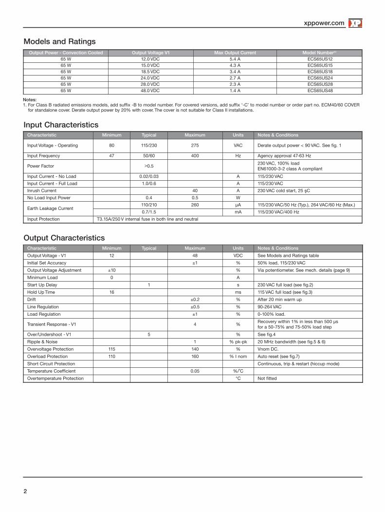
Input CharacteristicsCharacteristic Minimum Typical Maximum Units Notes & Conditions
Input Voltage - Operating 80 115/230 275 VAC Derate output power < 90 VAC. See fig. 1
Input Frequency 47 50/60 400 Hz Agency approval 47-63 Hz
Power Factor >0.5 230 VAC, 100% load EN61000-3-2 class A compliant
Input Current - No Load 0.02/0.03 A 115/230 VAC
Input Current - Full Load 1.0/0.6 A 115/230 VAC
Inrush Current 40 A 230 VAC cold start, 25 ºC
No Load Input Power 0.4 0.5 W
Earth Leakage Current110/210 260 µA 115/230 VAC/50 Hz (Typ.), 264 VAC/60 Hz (Max.)
0.7/1.5 mA 115/230 VAC/400 Hz
Input Protection T3.15A/250 V internal fuse in both line and neutral
Output CharacteristicsCharacteristic Minimum Typical Maximum Units Notes & Conditions
Output Voltage - V1 12 48 VDC See Models and Ratings table
Initial Set Accuracy ±1 % 50% load, 115/230 VAC
Output Voltage Adjustment ±10 % Via potentiometer. See mech. details (page 9)
Minimum Load 0 A
Start Up Delay 1 s 230 VAC full load (see fig.2)
Hold Up Time 16 ms 115 VAC full load (see fig.3)
Drift ±0.2 % After 20 min warm up
Line Regulation ±0.5 % 90-264 VAC
Load Regulation ±1 % 0-100% load.
Transient Response - V1 4 % Recovery within 1% in less than 500 µs for a 50-75% and 75-50% load step
Over/Undershoot - V1 5 % See fig.4
Ripple & Noise 1 % pk-pk 20 MHz bandwidth (see fig.5 & 6)
Overvoltage Protection 115 140 % Vnom DC.
Overload Protection 110 160 % I nom Auto reset (see fig.7)
Short Circuit Protection Continuous, trip & restart (hiccup mode)
Temperature Coefficient 0.05 %/˚C
Overtemperature Protection °C Not fitted
Models and Ratings
Notes:1. For Class B radiated emissions models, add suffix -B to model number. For covered versions, add suffix ‘-C’ to model number or order part no. ECM40/60 COVER
for standalone cover. Derate output power by 20% with cover. The cover is not suitable for Class II installations.
Output Power - Convection Cooled Output Voltage V1 Max Output Current Model Number(1)
65 W 12.0 VDC 5.4 A ECS65US1265 W 15.0 VDC 4.3 A ECS65US1565 W 18.5 VDC 3.4 A ECS65US1865 W 24.0 VDC 2.7 A ECS65US2465 W 28.0 VDC 2.3 A ECS65US2865 W 48.0 VDC 1.4 A ECS65US48

xppower.com
3
Start Up Delay From AC Turn OnFigure 2Start up example from AC turn on(230 VAC, 270 ms)
Hold Up Time From Loss of AC
Figure 3Hold up example at 65 W load with 115 VAC input (20.1 ms)
Input Voltage Derating
Figure. 1
40
50
80
60
70
90
100
80 9085 275
Input Voltage (VAC)
Out
put
Pow
er (%
)
Output Ripple & Noise
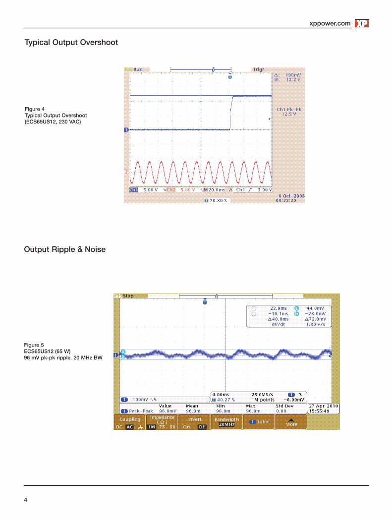
Figure 5ECS65US12 (65 W)96 mV pk-pk ripple. 20 MHz BW
xppower.com
4
Typical Output Overshoot
Figure 4Typical Output Overshoot(ECS65US12, 230 VAC)

Output Ripple & Noise cont.
Figure 6ECS65US24 (65 W)112 mV pk-pk ripple. 20 MHz BW
xppower.com
5
Output Overload Characteristic
Figure 7Typical OverloadCharacteristic (ECS65US12 shown)
0
2
4
6
8
10
12
14
0 1 2 3 4 5 6 7
Output Current (A)
Out
put
Vol
ts (V
)
Output enters Trip & Restart Mode

xppower.com
Xxxxxxxxxx
6
General Specifications
Characteristic Minimum Typical Maximum Units Notes & Conditions
Efficiency 88 % Full load (see fig.8 & 9 )
Isolation: Input to OutputInput to GroundOutput to Ground
4000 VAC
1500 VAC
500 VDC
Switching Frequency 65 kHz
Power Density 7.7 W/in3
Mean Time Between Failure 850 kHrs MIL-HDBK-217F, Notice 2 +25 °C GB
Weight 0.28 (125) lb (g)
Efficiency Versus Load
85%
65%
60%
75%
80%
90%
0% 20% 40% 60% 80% 100%
% of Output Load
Effic
ienc
y
115VAC230VAC
70%
65 %
75%
80%
90%
0% 20% 40% 60% 80% 100%
% of Output Load
Effic
ienc
y 115VAC230VAC
85%
Figure 8 - ECS65US12
Figure 9 - ECS65US24

xppower.com
Xxxxxxxxxx
7
EnvironmentalCharacteristic Minimum Typical Maximum Units Notes & Conditions
Operating Temperature -20 +70 °CDerate linearly from +50 °C at 2.5%/°C to 50% at 70 °C. (See fig.10 & ThermalConsiderations)
Storage Temperature -40 +85 °C
Cooling Convection Cooled See fig.10 & Thermal Considerations
Humidity 5 95 %RH Non-condensing
Operating Altitude 3000 m
Shock3 x 30 g/11 ms shocks in both +ve & -ve directions along the 3 orthogonal axis, total 18 shocks.
Vibration Three axis 5-500 Hz at 2 g x 10 sweeps
Electromagnetic Compatibility - Immunity
Phenomenon Standard Test Level Criteria Notes & Conditions
Low Voltage PSU EMC EN61204-3 High severity level as below
Harmonic Current EN61000-3-2 Class A
ESD Immunity EN61000-4-2 ±6 kV Contact±15 kV Air Discharge A
Radiated EN61000-4-3 3 A
EFT EN61000-4-4 3 A
Surges EN61000-4-5 Installation class 3 A
Conducted EN61000-4-6 3 A
Dips and Interruptions
EN61000-4-11
Dip: 30% 10 ms A
Dip: 60% 100 ms B
Dip: 100% 5000 ms B
EN60601-1-2
Dip: 30% 500 ms A
Dip: 60% 100 ms A Load derating with 115 VAC input (typically80% derate dependant on model & load)
Dip: 100% 10 ms A
Int.: >95% 5000 ms B
Figure 10
Derating Curve
75
40
50
80
37.5
60
70
90
100
-20 5040 60Ambient Temperature (ºC)
Open Frame
Out
put P
ower
(%)
30

xppower.com
8
Electromagnetic Compatibility - Emissions
Phenomenon Standard Test Level Criteria Notes & Conditions
Conducted EN55011/22 Class B See fig. 11
Radiated EN55011/22Class A
Class B ECS65-B models
Voltage Fluctuations EN61000-3-3
Safety Agency Approvals
.15 1 10 30
-10
0
10
20
30
40
50
60
70
80
MHz dBµV
PMM 8000 PLUS Name: Last Date: 01/05/10 Time: 08:08
Limit #1: 55022bqp Limit #2: 55022bav Detector: Average
Figure 11Typical conductednoise plot
Typical EMC Plot
Safety Agency Safety Standard Category
CB Report UL US/15901/UL IEC60950-1:2005 Ed 2 Information Technology
UL UL File #139109 UL60950-1 (2007), CSA 22.2 No.60950-1-07 Ed 2 Information Technology
TUV TUV Certificate # B 10 11 57396 082, EN60950-1:2006 Information Technology
CE LVD
Safety Agency Safety Standard Category
CB Report Certificate #US/17857/UL, IEC60601-1 Ed 3 Including Risk Management Medical
UL UL File # E146893, ANSI/AAMI ES 60601-1:2005 & CSA C22.2 No. 60601-1:08 Medical
TUV EN60601-1:2006 Medical
Equipment Protection Class Safety Standard Notes & Conditions
Class I (& Class II, B Models) IEC60950-1:2005 Ed 2 & IEC60601-1 Ed 3 See safety agency conditions ofacceptibility for details
Means of Protection Category
Primary to Secondary 2 x MOPP (Means of Patient Protection)
IEC60601-1 Ed 3Primary to Earth 1 x MOPP (Means of Patient Protection)
Secondary to Earth 1 x MOPP (Means of Patient Protection)
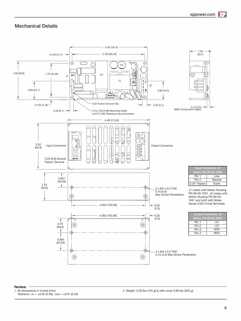
Mechanical Details
xppower.com
9
Notes1. All dimensions in inches (mm).
Tolerance .xx = ±0.02 (0.50); .xxx = ±0.01 (0.25)2. Weight: 0.28 lbs (125 g) & with cover 0.66 lbs (300 g)
Input Connector Output Connector
0.25 (0.6) Ground Faston Terminal
4.49 (114.0)
2.52(64.0)
1.54(39.0) 2 x M3 x 0.5 THD
0.16 (4.0)Max Screw Penetration
0.807(20.50)
4.055 (103.00)
0.22(5.5)
0.79(20.0)
4 x M3 x 0.5 THD0.16 (4.0) Max Screw Penetration
4.055 (103.00)
0.984(25.00)
0.22(5.5)
0.20 (5.1)
1.05 (26.7)
0.14 (3.5)SMD Component Height
2.00 (50.8)
0.95 (24.1)
0.125 (3.18)
1.75 (44.45)J1
0.96 (24.5)
0.20 (5.1)
J2
4.00 (101.6)
0.125 (3.17) 3.750 (95.25)
C5
C4
T1
Q1
0.25 Faston Ground Tab
4 X ø.156 (3.96) Mounting Holesø.312 (7.92) Clearance top and bottom
J1 mates with Molex HousingPN 09-50-1031, J2 mates withMolex Housing PN 09-50-1041 and both with MolexSeries 5194 Crimp Terminals
In put Connector J1Molex PN 09-65-2038Pin 1 LinePin 2 Neutral
0.25” Faston Earth
Output Connector J2Molex PN 09-65-2048Pin 1 +V1Pin 2 +V1Pin 3 RTNPin 4 RTN
20 Jan 16
xppower.com
Xxxxxxxxxx
10
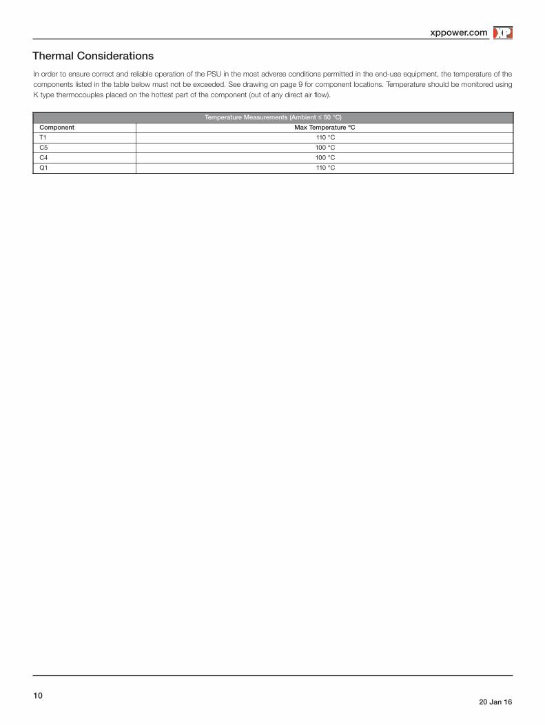
Thermal Considerations
Temperature Measurements (Ambient ≤ 50 °C)Component Max Temperature ºC
T1 110 °C
C5 100 °C
C4 100 °C
Q1 110 °C
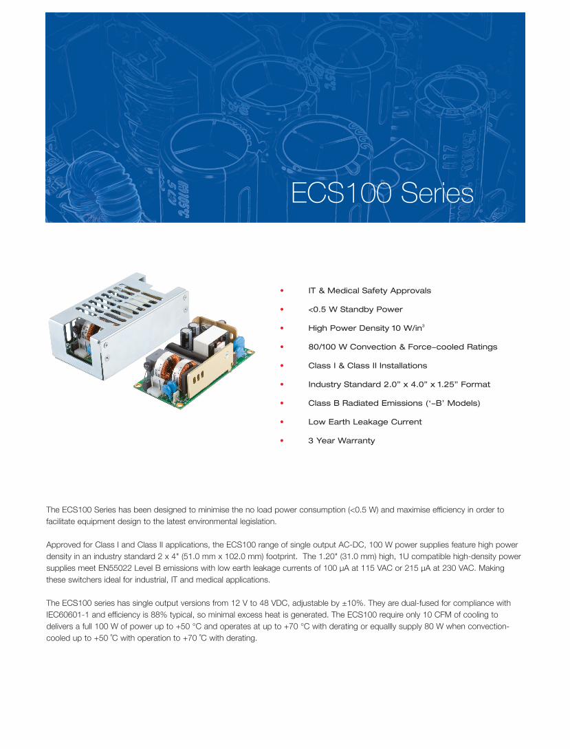
ECS100 Series
• IT & Medical Safety Approvals
• <0.5 W Standby Power
• High Power Density 10 W/in3
• 80/100 W Convection & Force-cooled Ratings
• Class I & Class II Installations
• Industry Standard 2.0” x 4.0” x 1.25” Format
• Class B Radiated Emissions (‘-B’ Models)
• Low Earth Leakage Current
• 3 Year Warranty

xppower.com
2
Input CharacteristicsCharacteristic Minimum Typical Maximum Units Notes & Conditions
Input Voltage - Operating 80 115/230 264 VAC Derate output power < 90 VAC. See fig. 1
Input Frequency 47 50/60 400 Hz Agency approval 47-63 Hz
Power Factor >0.5230 VAC, 100% load EN61000-3-2 class A compliant
Input Current - No Load 0.02/0.04 A 115/230 VAC
Input Current - Full Load 1.5/0.9 A 115/230 VAC
Inrush Current 40 A 230 VAC cold start, 25 ºC
No Load Input Power 0.3/0.4 0.5 W 115/230 VAC
Earth Leakage Current100/215 230 µA 115/230 VAC/50 Hz (Typ.), 264 VAC/60 Hz (Max.)
0.5/1.1 mA 115/230 VAC/400 Hz
Input Protection T3.15A/250 V internal fuse in both line and neutral
Output CharacteristicsCharacteristic Minimum Typical Maximum Units Notes & Conditions
Output Voltage - V1 12 48 VDC See Models and Ratings table
Initial Set Accuracy ±1 % 50% load, 115/230 VAC
Output Voltage Adjustment ±10 % Via potentiometer. See mech. details (page 9)
Minimum Load 0 A
Start Up Delay 1 s 230 VAC full load (see fig.2)
Hold Up Time 16 ms 115 VAC full load (see fig.3)
Drift ±0.2 % After 20 min warm up
Line Regulation ±0.5 % 90-264 VAC
Load Regulation ±1 % 0-100% load.
Transient Response - V1 4 %Recovery within 1% in less than 500 µs for a 50-75% and 75-50% load step
Over/Undershoot - V1 5 % See fig.4
Ripple & Noise 1 % pk-pk 20 MHz bandwidth (see fig.5 & 6)
Overvoltage Protection 115 140 % Vnom DC.
Overload Protection 110 150 % I nom Auto reset (see fig.7)
Short Circuit Protection Continuous, trip & restart (hiccup mode)
Temperature Coefficient 0.05 %/˚C
Overtemperature Protection °C Not fitted
Models and Ratings - Convection-cooled
Notes:1. For Class B radiated emissions models, add suffix -B to model number. For covered versions, add suffix ‘-C’ to model number or order part no. ECM40/60 COVERfor standalone cover. Derate output power by 20% with cover. The cover is not suitable for Class II installations.
Output PowerOutput Voltage V1 Max Output Current Model Number(1)
Forced Cooled (10 CFM) Convection Cooled100 W 80 W 12.0 VDC 8.3 A ECS100US12100 W 80 W 15.0 VDC 6.7 A ECS100US15100 W 80 W 18.0 VDC 5.5 A ECS100US18100 W 80 W 24.0 VDC 4.2 A ECS100US24100 W 80 W 28.0 VDC 3.6 A ECS100US28100 W 80 W 48.0 VDC 2.1 A ECS100US48

xppower.com
3
Start Up Delay From AC Turn OnFigure 2Start up example from AC turn on(230 VAC, 720 ms)
Hold Up Time From Loss of AC
Figure 3Hold up example at 100 W load with 115 VAC input (17.2ms)
Input Voltage Derating
Figure. 1
40
50
80
60
70
90
100
80 9085 264
Input Voltage (VAC)
Out
put
Pow
er (%
)
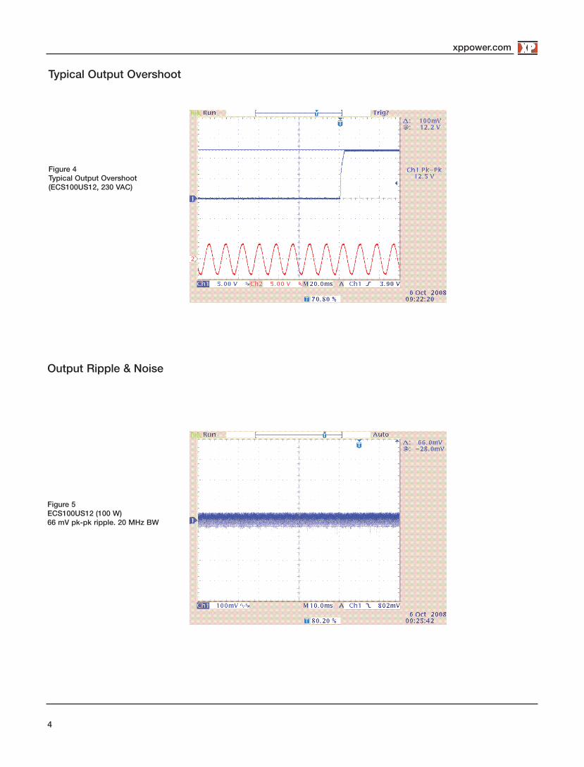
Output Ripple & Noise
Figure 5ECS100US12 (100 W)66 mV pk-pk ripple. 20 MHz BW
xppower.com
4
Typical Output Overshoot
Figure 4Typical Output Overshoot(ECS100US12, 230 VAC)

Output Ripple & Noise cont.
Figure 6ECS100US24 (100 W)58 mV pk-pk ripple. 20 MHz BW
xppower.com
5
Output Overload Characteristic
Figure 7Typical OverloadCharacteristic(ECS100US12 shown)
Output enters Trip & Restart Mode
0
2
4
6
8
10
12
14
0 1 2 3 6 7 8 9 10
Output Current (A)
Outp
ut V
olts
(V)

xppower.com
Xxxxxxxxxx
6
General Specifications
Characteristic Minimum Typical Maximum Units Notes & Conditions
Efficiency 88 % Full load (see fig.8 & 9 )
Isolation: Input to OutputInput to GroundOutput to Ground
4000 VAC
1500 VAC
500 VDC
Switching Frequency 65 kHz
Power Density 10 W/in3
Mean Time Between Failure834
kHrsMIL-HDBK-217F, Notice 2 +25 °C GB
1245 Telecordia SR-332 +25 ºC
Weight 0.4 (175) lb (g)
Efficiency Versus Load
81.00%
82.00%
83.00%
84.00%
85.00%
86.00%
87.00%
88.00%
89.00%
0 20 40 60 80 100
Effic
ienc
y
Output Load Wattage (W)
83.00%
84.00%
85.00%
86.00%
87.00%
88.00%
89.00%
90.00%
91.00%
0 20 40 60 80 100
Effic
ienc
y (%
)
Output Load Wattage (W)
y p
Figure 8ECS100US12 at 230 VAC
Figure 9ECS100US24 at 230 VAC
xppower.com
Xxxxxxxxxx
7
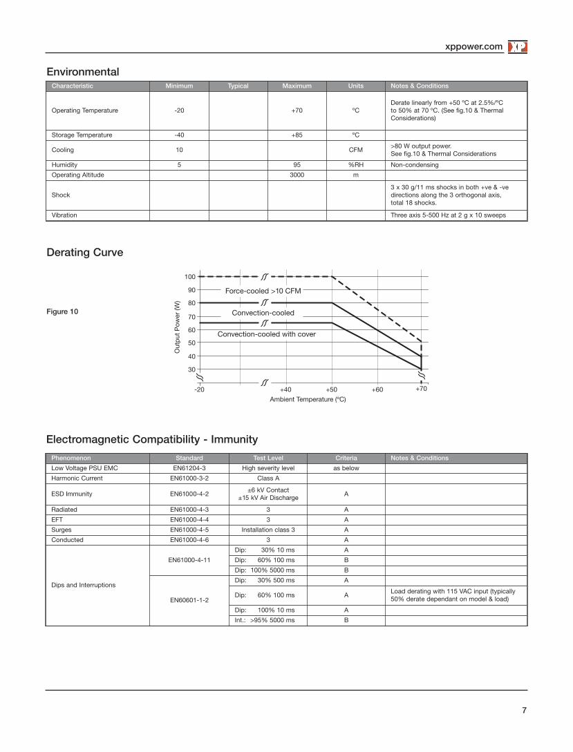
EnvironmentalCharacteristic Minimum Typical Maximum Units Notes & Conditions
Operating Temperature -20 +70 ºCDerate linearly from +50 ºC at 2.5%/ºC to 50% at 70 ºC. (See fig.10 & ThermalConsiderations)
Storage Temperature -40 +85 ºC
Cooling 10 CFM>80 W output power. See fig.10 & Thermal Considerations
Humidity 5 95 %RH Non-condensing
Operating Altitude 3000 m
Shock3 x 30 g/11 ms shocks in both +ve & -ve directions along the 3 orthogonal axis, total 18 shocks.
Vibration Three axis 5-500 Hz at 2 g x 10 sweeps
Electromagnetic Compatibility - Immunity
Phenomenon Standard Test Level Criteria Notes & Conditions
Low Voltage PSU EMC EN61204-3 High severity level as below
Harmonic Current EN61000-3-2 Class A
ESD Immunity EN61000-4-2 ±6 kV Contact±15 kV Air Discharge A
Radiated EN61000-4-3 3 A
EFT EN61000-4-4 3 A
Surges EN61000-4-5 Installation class 3 A
Conducted EN61000-4-6 3 A
Dips and Interruptions
EN61000-4-11
Dip: 30% 10 ms A
Dip: 60% 100 ms B
Dip: 100% 5000 ms B
EN60601-1-2
Dip: 30% 500 ms A
Dip: 60% 100 ms ALoad derating with 115 VAC input (typically50% derate dependant on model & load)
Dip: 100% 10 ms A
Int.: >95% 5000 ms B
Figure 10
Derating Curve
+70
40
50
80
60
70
90
100
-20 +50+40 +60
Ambient Temperature (ºC)
Out
put
Pow
er (W
)
30
Force-cooled >10 CFM
Convection-cooled
Convection-cooled with cover

xppower.com
8
Electromagnetic Compatibility - Emissions
Phenomenon Standard Test Level Criteria Notes & Conditions
Conducted EN55011/22 Class B See fig. 11
Radiated EN55011/22Class A
Class B ECS100-B Models
Voltage Fluctuations EN61000-3-3
Safety Agency Approvals
Figure 11Typical conductednoise plot (Class I)
Typical EMC Plot
Safety Agency Safety Standard Category
CB Report UL US/13728/UL IEC60950-1:2005 Ed 2 Information Technology
UL UL File #139109 UL60950-1 (2007), CSA 22.2 No.60950-1-07 Ed 2 Information Technology
TUV TUV Certificate # B 09 04 57396 059, EN60950-1:2006 Information Technology
CE LVD
Safety Agency Safety Standard Category
CB Report IEC60601-1 Ed 3 Including Risk Management Medical
UL UL File # E146893, ANSI/AAMI ES 60601-1:2005 & CSA C22.2 No. 60601-1:08 Medical
TUV EN60601-1:2006 Medical
Equipment Protection Class Safety Standard Notes & Conditions
Class I & Class II IEC60950-1:2005 Ed 2 & IEC60601-1 Ed 3See safety agency conditions ofacceptability for details
Means of Protection Category
Primary to Secondary 2 x MOPP (Means of Patient Protection)
IEC60601-1 Ed 3Primary to Earth 1 x MOPP (Means of Patient Protection)
Secondary to Earth 1 x MOPP (Means of Patient Protection)

Mechanical Details
Open Frame Versions
‘-B’ Model
xppower.com
9
Notes1. All dimensions in inches (mm).Tolerance .xx = ±0.02 (0.50); .xxx = ±0.01 (0.25)
2. Weight: 0.4 lbs (175 g) (Open Frame)
4.00 (101.6)
C5T1
C4
0.125 (3.18)
1.00 (25.4)
0.125 (3.18)
0.20 (5.1)
0.25 Faston Ground Tab4 X ø.156 (3.96) Mounting Holesø.312 (7.92) Clearance top and bottom
1.01 (25.7)
Voltage Adj.
1.750 (44.45)
J1
J2
3.750 (95.25)
Q1
0.20 (5.1)
2.00 +0.06/-0.00(50.8 +1.5/-0.00)
1.25 (31.8)
0.14 (3.5)SMD Component
Height
4.50 (114.3)
3.75 (95.25)
J1
J2
0.37 (9.52)
1.75 (44.45)
1.01 (25.7)
0.125 (3.18)
0.20 (5.1)
0.10 (2.5)
0.25 Faston Ground Tab
4 X ø.156 (3.96) Mounting Holesø.312 (7.92) Clearance top and bottom
0.20 (5.1)
2.00 +0.06/-0.0050.8 +1.5/-0.00)
1.25 (31.8)
0.14 (3.5)SMD Component
Height
1.00 (25.4)
J1 mates with Molex HousingPN 09-50-1031,J2 mates with Molex HousingPN 09-50-1041 and bothwith Molex Series 5194 CrimpTerminals
In put Connector J1Molex PN 09-65-2038
Pin 1 Line
Pin 2 Neutral
0.25” Faston Earth
Output Connector J2Molex PN 09-65-2048Pin 1 +V1Pin 2 +V1Pin 3 RTNPin 4 RTN
20 Jan 17
Thermal Considerations
Temperature Measurements (Ambient ≤ 50 ºC)Component Max Temperature ºC
T1 110 ºC
C5 100 ºC
C4 100 ºC
Q1 110 ºC
xppower.com
10
Covered Versions -C (not available for -B models)
Input Connector Output Connector
0.25 (0.6) Ground Faston Terminal
4.49 (114.0)
2.52(64.0)
1.54(39.0) 2 x M3 x 0.5 THD
0.16 (4.0)Max Screw Penetration
0.807(20.50)
4.055 (103.00)
0.22(5.5)
0.79(20.0)
4 x M3 x 0.5 THD0.16 (4.0) Max Screw Penetration
4.055 (103.00)
0.984(25.00)
0.22(5.5)
Notes1. All dimensions in inches (mm).Tolerance .xx = ±0.02 (0.50); .xxx = ±0.01 (0.25)
2. Weight: 0.4 lbs (175 g) (Open Frame)
J1 mates with Molex HousingPN 09-50-1031,J2 mates with Molex HousingPN 09-50-1041 and bothwith Molex Series 5194 CrimpTerminals
In put Connector J1Molex PN 09-65-2038
Pin 1 Line
Pin 2 Neutral
0.25” Faston Earth
Output Connector J2Molex PN 09-65-2048Pin 1 +V1Pin 2 +V1Pin 3 RTNPin 4 RTN

ECS130 Series
• IT & Medical Safety Approvals
• Industry Standard 2.0” x 4.0 x 1.25” Format
• < 0.5W Standby Power
• Convection & Forced Cooled Ratings
• -40° C to +70° C Operation
• Class I & Class II Installations
• Low Earth Leakage Current
• Class B Emissions
• 3 Year Warranty
μ μ
POWERGREEN

xppower.com
2
Input Characteristics
Characteristic Minimum Typical Maximum Units Notes & Conditions
Input Voltage - Operating 80 115/230 264 VAC See derating curve. See fig 1.
Input Frequency 47 50/60 63 Hz
Power Factor >0.5 230 VAC, 100% load EN61000-3-2 Class A Compliant.
Input Current - No Load 0.03 A
Input Current - Full Load 1.9/1.1 A 115/230 VAC
Inrush Current 40 A 230 VAC cold start 25 °C
No Load Input Power 0.5 W
Earth Leakage Current 260 µA 264 VAC/60 Hz (Max.)
Input Protection F3.15 A/250 V internal fuse in both lines
Output Characteristics
Characteristic Minimum Typical Maximum Units Notes & Conditions
Output Voltage - V1 12 48 VDC See Models and Ratings table
Initial Set Accuracy ±1 % 50% load, 115/230 VAC
Output Voltage Adjustment -V1 ±10 % Via potentiometer. See mech. details,
Minimum Load 0 A
Start Up Delay 1 s 115/230 VAC full load
Hold Up Time 18 ms
Drift ±0.2 % After 20 min warm up
Line Regulation ±0.5 % 90-264 VAC
Load Regulation % 0-100% load
Transient Response - V1 4 % Recovery within 1% in less than 500 µs for a 50-75% and 75-50% load step
Over/Undershoot - V1 5 %
Ripple & Noise - V1 1 % pk-pk 20 MHz bandwidth, 12V Models 1.5% max
Overvoltage Protection - V1 115 140 % Vnom DC. Output 1, recycle input to reset
Overload Protection - V1 110 160 % I nom See fig. 2. Trip and Restart
Short Circuit Protection - V1 Continuous
Temperature Coefficient 0.05 %/˚C
Overtemperature Protection °C Not fitted
Models and Ratings
1. For covered versions, add suffix ‘-C’ to model number or order part no. ECM40/60 COVER for standalone cover, see derating curve. The cover is not suitable for Class II installations. ‘-C’.
Output PowerOutput Voltage Output Current Model Number(1)
Forced Cooled (10 CFM) Convection-cooled
130 W 100 W 12.0 VDC 10.9 A ECS130US12†^
130 W 100 W 15.0 VDC 8.7 A ECS130US15†^
130 W 100 W 18.0 VDC 7.3 A ECS130US18
130 W 100 W 24.0 VDC 5.4 A ECS130US24†^
130 W 100 W 28.0 VDC 4.7 A ECS130US28†^
130 W 100 W 48.0 VDC 2.7 A ECS130US48†^
xppower.com
3
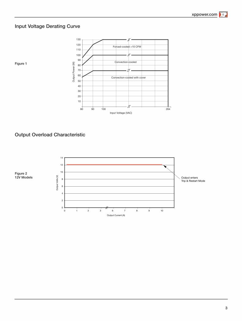
Input Voltage Derating Curve
Output Overload Characteristic
Figure 1
2010
3040
50
60
7080
90100
110120
130
80 10090 264Input Voltage (VAC)
Outp
ut P
ower
(W)
Forced-cooled >10 CFM
Convection-cooled
Convection-cooled with cover
Output enters Trip & Restart Mode
0
2
4
6
8
10
12
14
0 1 2 3 6 7 8 9 10
Output Current (A)
Outp
ut V
olts
(V)Figure 2
12V Models

xppower.com
4
Efficiency Versus Load
General Specifications
Characteristic Minimum Typical Maximum Units Notes & Conditions
Efficiency 88 % 230 VAC Full load (see fig.3-5 )
Isolation: Input to OutputInput to GroundOutput to Ground
4000 VAC
1500 VAC
500 VDC
Switching Frequency 65 kHz
Power Density 13 W/in3
Mean Time Between Failure 715 kHrs MIL-HDBK-217F, Notice 2 +25 °C GB
Weight: Open FrameCovered Unit
0.40 (0.18) lb (kg)
0.80 (0.36) lb (kg)
Figure 5 - 48V Models
Figure 3 - 12V Models
Figure 4 - 24V Models
20% 25% 50% 75% 100%
115 V
230 V
0.00%
10.00%
20.00%
30.00%
40.00%
50.00%
60.00%
70.00%
80.00%
90.00%
100.00%
Load %
Effici
ency
(%)
0.00%
10.00%
20.00%
30.00%
40.00%
50.00%
60.00%
70.00%
80.00%
90.00%
100.00%
20% 25% 50% 75% 100%
115 V
230 V
Load %
Effici
ency
(%)
20% 25% 50% 75% 100%
115 V
230 V
0.00%
10.00%
20.00%
30.00%
40.00%
50.00%
60.00%
70.00%
80.00%
90.00%
100.00%
Load %
Effici
ency
(%)
xppower.com
5
Environmental
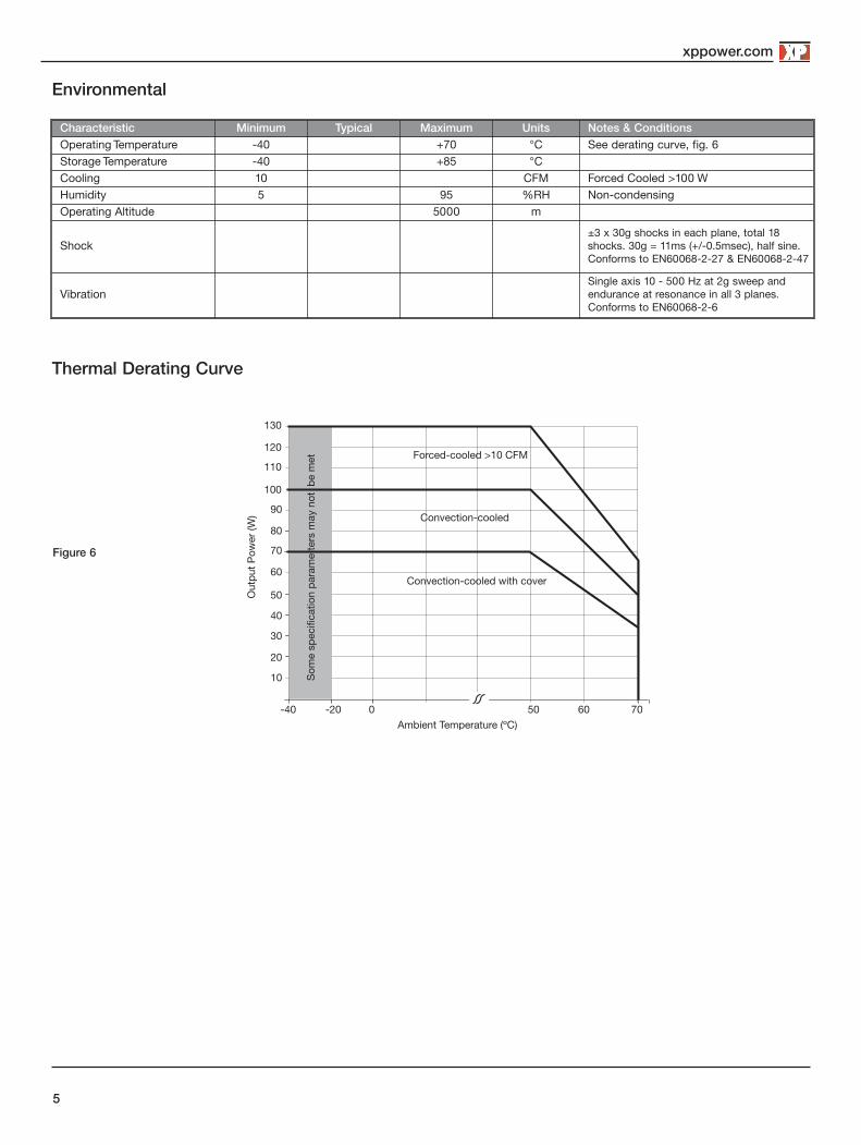
Thermal Derating Curve
Characteristic Minimum Typical Maximum Units Notes & ConditionsOperating Temperature -40 +70 °C See derating curve, fig. 6Storage Temperature -40 +85 °CCooling 10 CFM Forced Cooled >100 WHumidity 5 95 %RH Non-condensingOperating Altitude 5000 m
Shock±3 x 30g shocks in each plane, total 18shocks. 30g = 11ms (+/-0.5msec), half sine.Conforms to EN60068-2-27 & EN60068-2-47
VibrationSingle axis 10 - 500 Hz at 2g sweep andendurance at resonance in all 3 planes.Conforms to EN60068-2-6
Figure 6
Ambient Temperature (ºC)
Outp
ut P
ower
(W)
2010
3040
50
60
7080
90100
110120
130
-40 0-20 6050 70
Forced-cooled >10 CFM
Convection-cooled
Convection-cooled with cover
Som
e sp
ecific
atio
n pa
ram
e te
rs m
ay n
ot b
e m
et

xppower.com
6
Electromagnetic Compatibility - ImmunityPhenomenon Standard Test Level Criteria Notes & Conditions
Low Voltage PSU EMC EN61204-3 High severity level as below
Harmonic Current EN61000-3-2 Class A
ESD Immunity EN61000-4-2 ±6 kV Contact±15 kV Air Discharge A
Radiated EN61000-4-3 3 A
EFT EN61000-4-4 3 A
Surges EN61000-4-5 Installation class 3 A
Conducted EN61000-4-6 3 A
Dips and Interruptions
EN55024(100 VAC)
Dip >95% (0 VAC), 8.3ms B
Dip 30% (70 VAC), 416ms B
Dip >95% (0 VAC), 4160ms B
EN55024(240 VAC)
Dip >95% (0 VAC), 10.0ms B
Dip 30% (168 VAC), 500ms B
Dip >95% (0 VAC), 5000ms B
EN60601-1-2 (100 VAC)
Dip >95% (0 VAC), 10.0ms A Derate Output Power to 100 W
Dip 60% (40 VAC), 100ms A Derate Output Power to 12 W
Dip 30% (70 VAC), 500ms A Derate Output Power to 100 W
Dip >95% (0 VAC), 5000ms B
EN60601-1-2 (240 VAC)
Dip >95% (0 VAC), 10.0ms A
Dip 60% (96 VAC), 100ms A
Dip 30% (168 VAC), 500ms A
Dip >95% (0 VAC), 5000ms B
Electromagnetic Compatibility - Emissions Phenomenon Standard Test Level Criteria Notes & Conditions
Conducted EN55011/22 Class B
Radiated EN55011/22 Class A
Voltage Fluctuations EN61000-3-3
Safety Agency Approvals
Safety Agency Safety Standard Category
CB Report IEC60950-1:2005 Ed 2 Information Technology
UL UL60950-1 (2007), CSA 22.2 No.60950-1-07 Ed 2 Information Technology
TUV EN60950-1:2006 Information Technology
CE LVD
Safety Agency Safety Standard Category
CB Report IEC60601-1 Ed 3 Including Risk Management Medical
UL ANSI/AAMI ES60601-1:2005 & CSA C22.2, No.60601-1:08 Medical
TUV EN60601-1/A12:2006 Medical
Equipment Protection Class Safety Standard Notes & Conditions
Class I & Class II IEC60950-1:2005 Ed 2 & IEC60601-1 Ed 2 See safety agency conditions of acceptibilityfor details
Means of Protection Category
Primary to Secondary 2 x MOPP (Means of Patient Protection)
IEC60601-1 Ed 3Primary to Earth 1 x MOPP (Means of Patient Protection)
Secondary to Earth 1 x MOPP (Means of Patient Protection)

xppower.com
Xxxxxxxxxx
7
Mechanical Details - ECC100USxx
Notes1. All dimensions in inches (mm).
Tolerance .xx = ±0.02 (0.50); .xxx = ±0.01 (0.25)2. Weight: 0.386 lbs (175 g)
Mechanical Details
SMD COMPONENT HEIGHT
4X 0.156 (3.96) MOUNTING HOLES0.312 (7.92) CLEARANCE TOP AND BOTTOM
J2T1
Q1
C4
C5
3.750 (95.25)
4.00 (101.6)
0.15 (3.8)
0.125 (3.17)
0.20 (5.1)
0.20 (5.1)
.25 FASTONGROUND TAB
J11.75 (44.45)
0.12 (3.18)
1.00 (25.4) 1.05 (26.7)
Voltage Adjust
1.28 (32.5)
1
4
1
2N
L
2.00 +0.06/-0.00(50.8 +1.5/-0.00)
J1 mates with Molex Housing PN 09-50-1031, J2 mates with Molex Housing PN 09-50-1041and both with Molex Series 5194 Crimp Terminals
In put Connector J1Molex PN 09-65-2038Pin 1 LinePin 2 Neutral
0.25” Faston Earth
Output Connector J2Molex PN 09-65-2048Pin 1 +V1Pin 2 +V1Pin 3 RTNPin 4 RTN
xppower.com
8
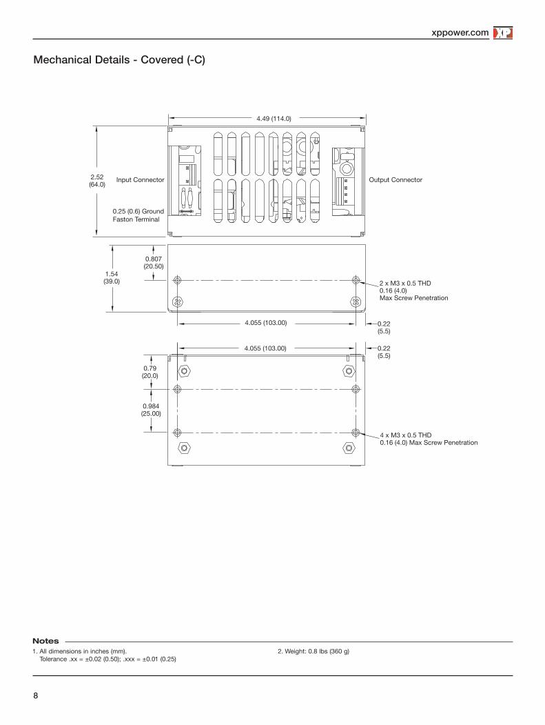
Notes1. All dimensions in inches (mm).
Tolerance .xx = ±0.02 (0.50); .xxx = ±0.01 (0.25)2. Weight: 0.8 lbs (360 g)
Mechanical Details - Covered (-C)
Input Connector Output Connector
0.25 (0.6) Ground Faston Terminal
4.49 (114.0)
2.52(64.0)
1.54(39.0) 2 x M3 x 0.5 THD
0.16 (4.0)Max Screw Penetration
0.807(20.50)
4.055 (103.00)
0.22(5.5)
0.79(20.0)
4 x M3 x 0.5 THD0.16 (4.0) Max Screw Penetration
4.055 (103.00)
0.984(25.00)
0.22(5.5)

xppower.com
XxxxxxxxxxThermal Considerations
Temperature Measurements (Ambient 50 °C )
Component Max Temperature ° C
T1 Coil 120 ° C
Q1 Body 120 ° C
C5 105 ° C
C4 105 ° C
Service Life
5000
25000
45000
65000
85000
105000
125000
145000
165000
185000
105 95 85 75 65
C5 Temperature (°C)
Lifet
ime
(Hrs
)
55
Estimated Service Life vs Component Temperature
20-Jan-17