ecs 152a physical layer acknowledgement: slides from prof. prasant mohapatra
Post on 19-Dec-2015
224 views
TRANSCRIPT
ECS 152A
Physical Layer
Acknowledgement: Slides from Prof. Prasant Mohapatra
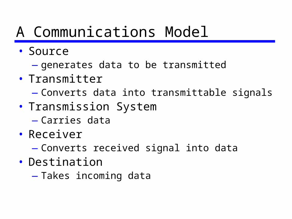
A Communications Model• Source
—generates data to be transmitted
• Transmitter—Converts data into transmittable signals
• Transmission System—Carries data
• Receiver—Converts received signal into data
• Destination—Takes incoming data
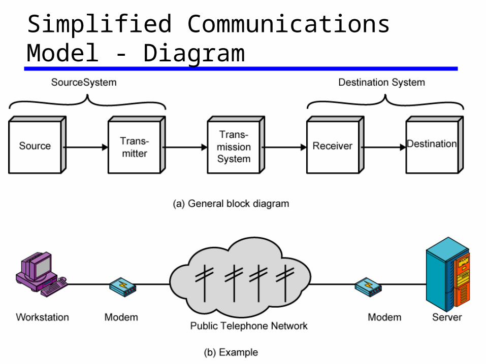
Simplified Communications Model - Diagram
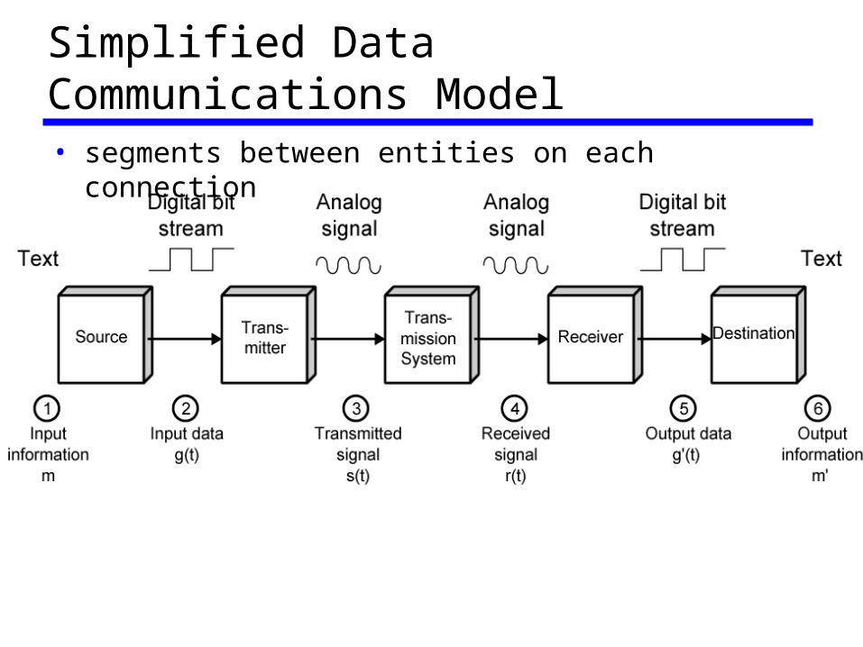
Simplified Data Communications Model• segments between entities on each connection
Key points• All forms of information can be represented by
electromagnetic signals. Based on transmission medium and the comm. environment, either analog or digital signals can be used
• Any EM signal is made up of a # of constituent frequencies -> bandwidth of the signal
• Transmission impairment: attenuation, delay distortion, noise, etc.
• Design factors: signal bw, data rate of digital information, noise level, error rate.
Terminology (1)• Transmitter• Receiver• Medium
—Guided medium• e.g. twisted pair, optical fiber, coaxial cable
—Unguided medium• e.g. air, water, vacuum
Terminology (2)• Direct link
—No intermediate devices
• Point-to-point—Direct link —Only 2 devices share link
• Multi-point—More than two devices share the link
Terminology (3)• Simplex
—One direction• e.g. Television
• Half duplex—Either direction, but only one way at a time
• e.g. police radio
• Full duplex—Both directions at the same time
• e.g. telephone
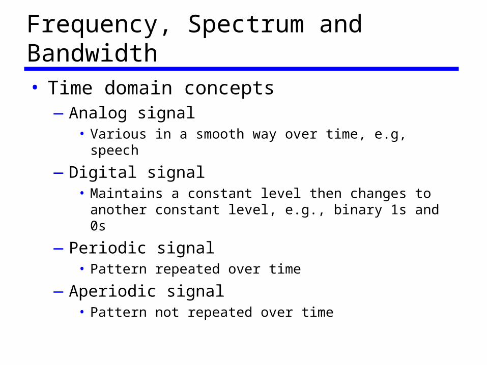
Frequency, Spectrum and Bandwidth• Time domain concepts
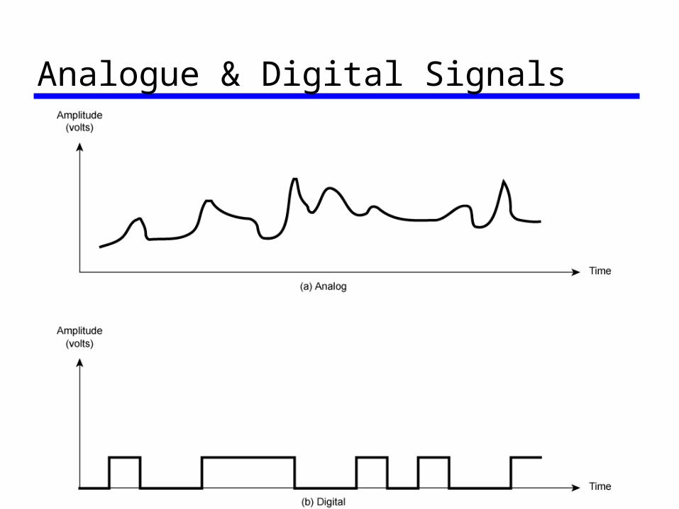
—Analog signal• Various in a smooth way over time, e.g, speech
—Digital signal• Maintains a constant level then changes to another
constant level, e.g., binary 1s and 0s
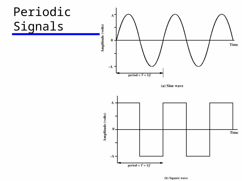
—Periodic signal• Pattern repeated over time
—Aperiodic signal• Pattern not repeated over time
Analogue & Digital Signals
PeriodicSignals
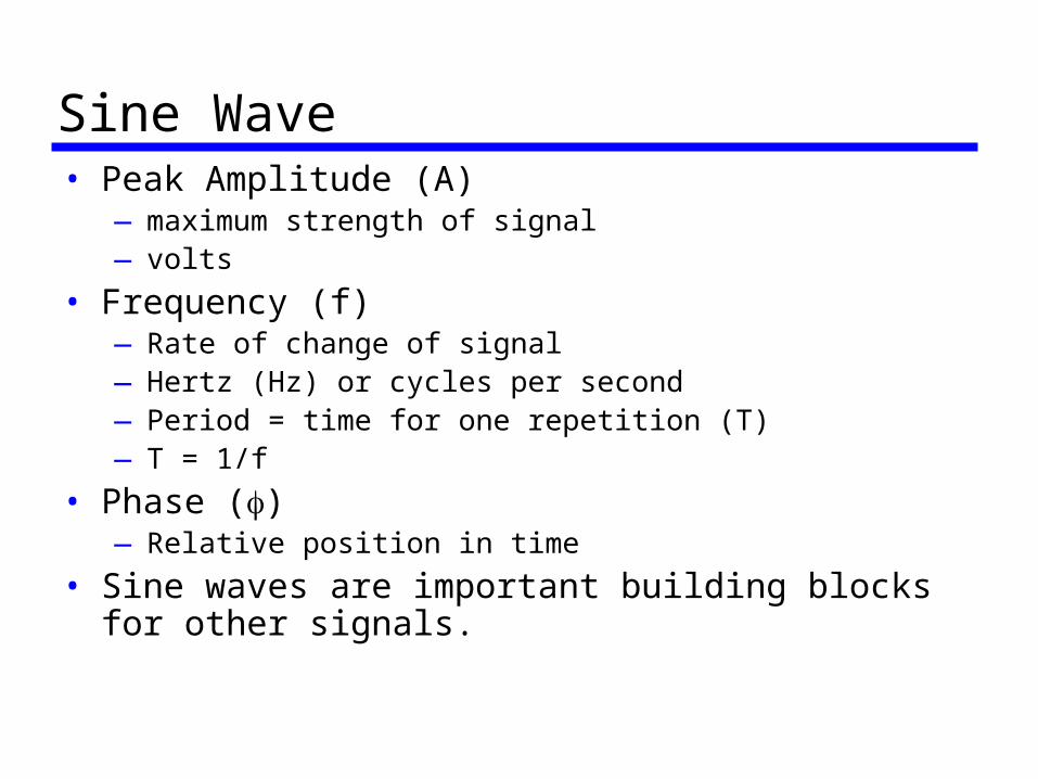
Sine Wave• Peak Amplitude (A)
—maximum strength of signal—volts
• Frequency (f)—Rate of change of signal—Hertz (Hz) or cycles per second—Period = time for one repetition (T)—T = 1/f
• Phase ()—Relative position in time
• Sine waves are important building blocks for other signals.
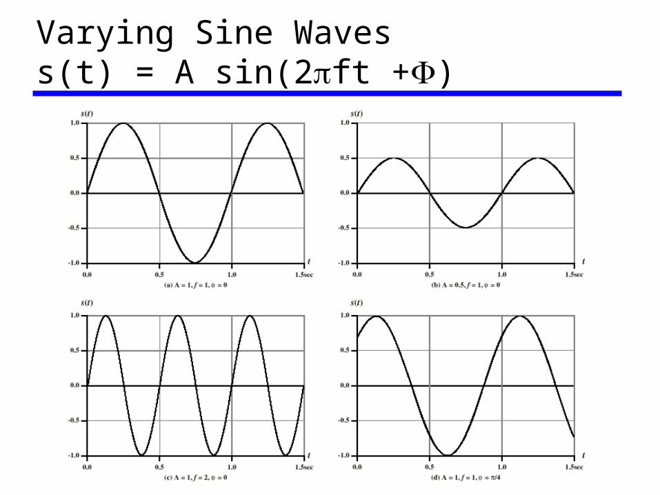
Varying Sine Wavess(t) = A sin(2ft +)
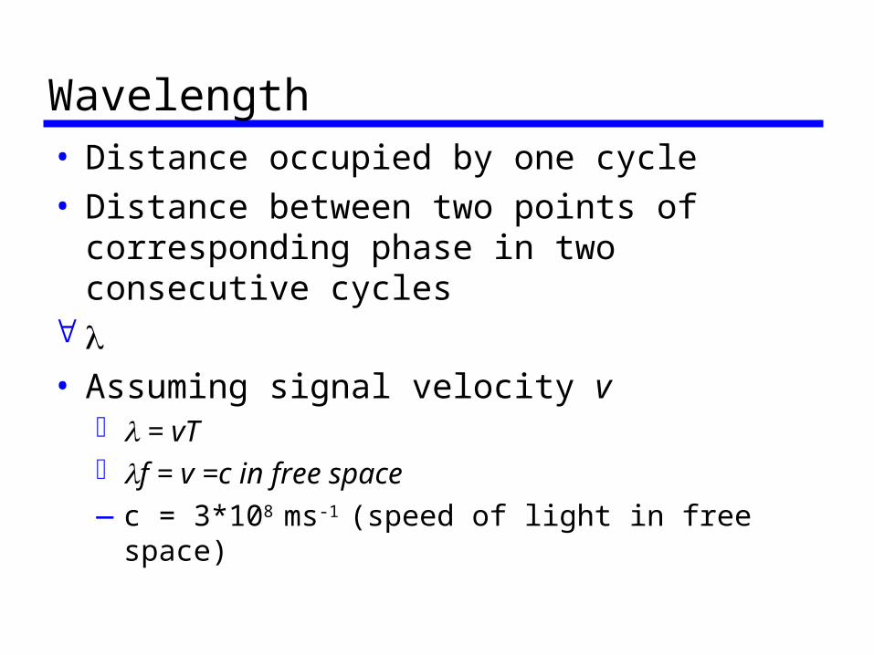
Wavelength• Distance occupied by one cycle• Distance between two points of
corresponding phase in two consecutive cycles
• Assuming signal velocity v
= vT f = v =c in free space—c = 3*108 ms-1 (speed of light in free space)
Frequency Domain Concepts• Signal usually made up of many
frequencies• Components are sine waves• Can be shown (Fourier analysis) that any
signal is made up of component sine waves
• Can plot frequency domain functions
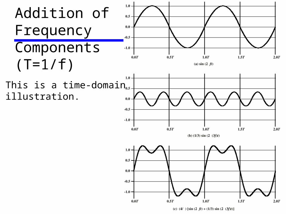
Addition of FrequencyComponents(T=1/f)
This is a time-domainillustration.
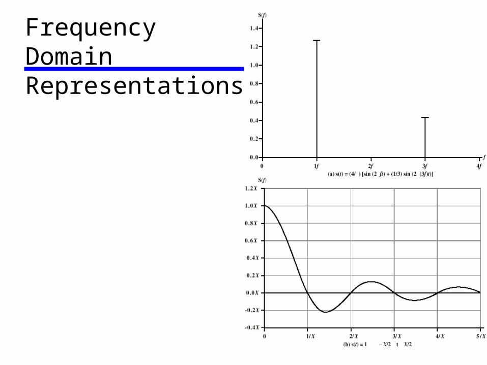
FrequencyDomainRepresentations
Spectrum & Bandwidth• Spectrum
—range of frequencies contained in signal
• Absolute bandwidth—width of spectrum
• Effective bandwidth—Often just bandwidth—Narrow band of frequencies containing most of
the energy
• DC Component—Component of zero frequency
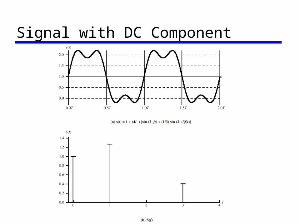
Signal with DC Component

Data Rate and Bandwidth• Any transmission system has a limited
band of frequencies• This limits the data rate that can be
carried• We will see two limits later
Analog and Digital Data Transmission• Data
—Entities that convey meaning
• Signals—Electric or electromagnetic representations of
data
• Transmission—Communication of data by propagation and
processing of signals
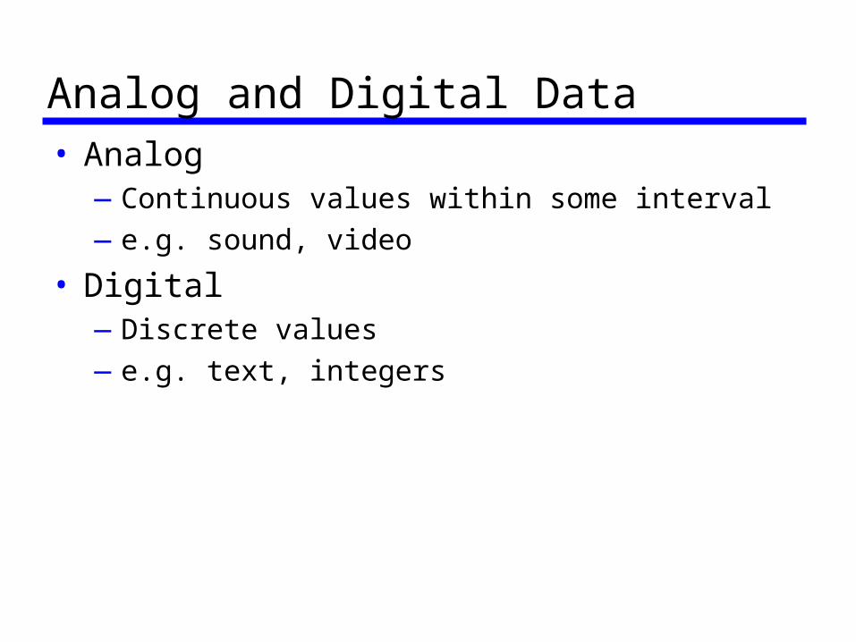
Analog and Digital Data• Analog
—Continuous values within some interval—e.g. sound, video
• Digital—Discrete values—e.g. text, integers
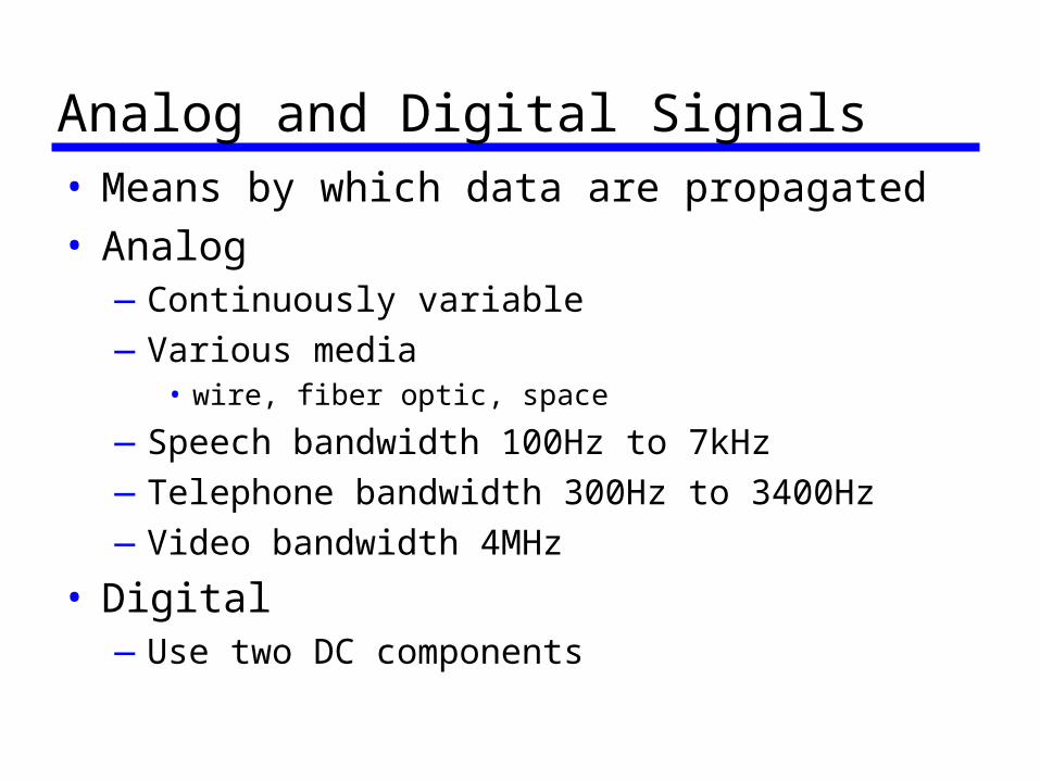
Analog and Digital Signals• Means by which data are propagated• Analog
—Continuously variable—Various media
• wire, fiber optic, space
—Speech bandwidth 100Hz to 7kHz—Telephone bandwidth 300Hz to 3400Hz—Video bandwidth 4MHz
• Digital—Use two DC components
Advantages & Disadvantages of Digital• Cheaper• Less susceptible to noise• Greater attenuation
—Pulses become rounded and smaller—Leads to loss of information
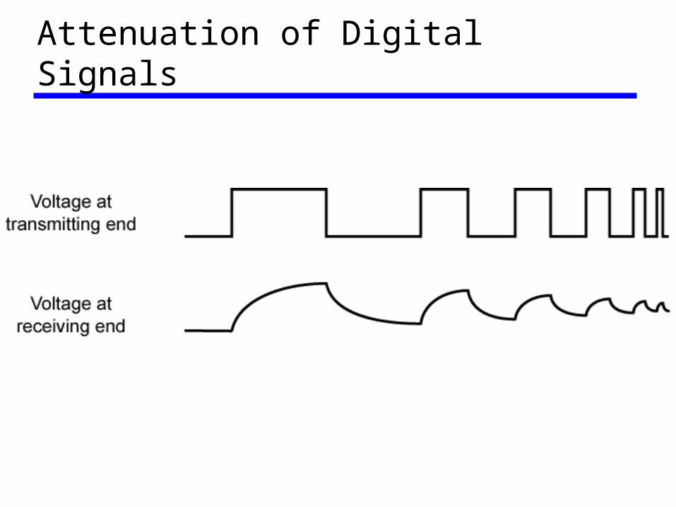
Attenuation of Digital Signals
Binary Digital Data• From computer terminals etc.• Two dc components• Bandwidth depends on data rate
Data and Signals• Usually use digital signals for digital data
and analog signals for analog data• Can use analog signal to carry digital data
—Modem
• Can use digital signal to carry analog data —Compact Disc audio
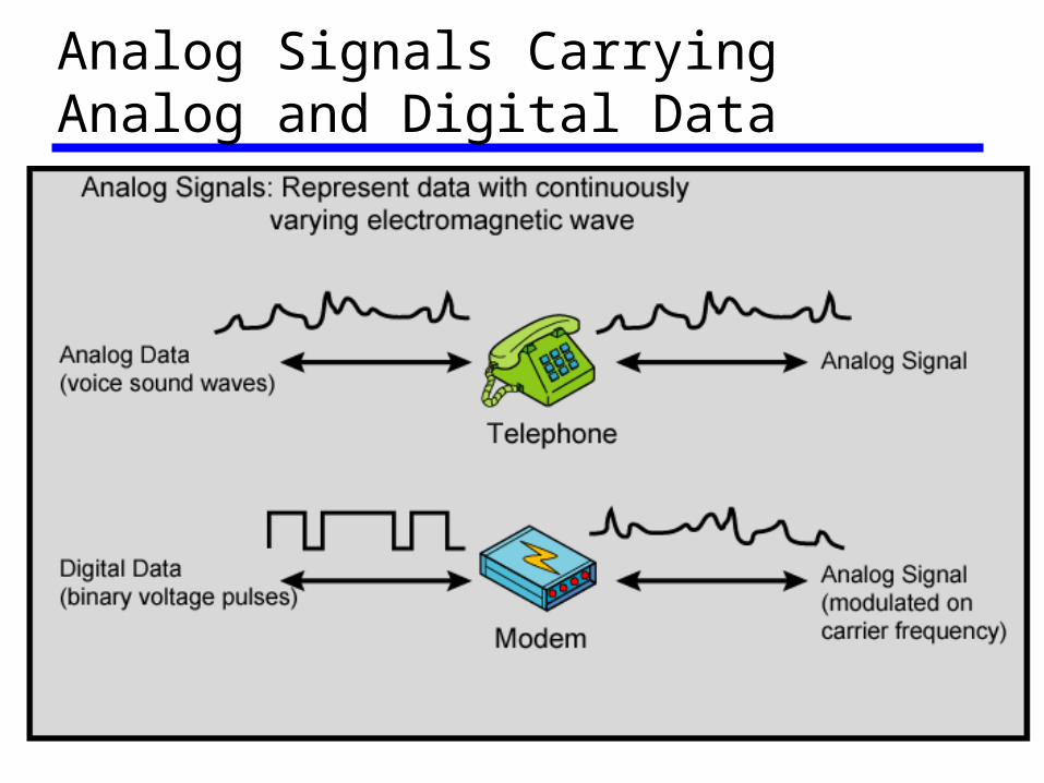
Analog Signals Carrying Analog and Digital Data
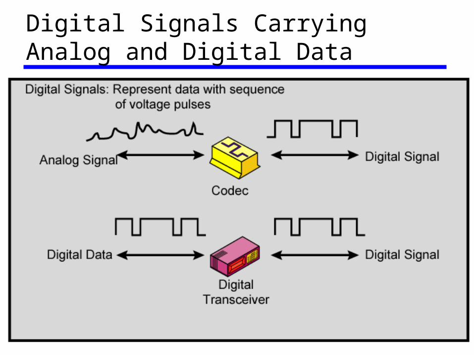
Digital Signals Carrying Analog and Digital Data
Analog Transmission• Analog signal transmitted without regard
to content• May be analog or digital data• Attenuated over distance • Use amplifiers to boost signal• Also amplifies noise
Digital Transmission• Concerned with content• Integrity endangered by noise,
attenuation etc.• Repeaters used• Repeater receives signal• Extracts bit pattern• Retransmits• Attenuation is overcome• Noise is not amplified
Advantages of Digital Transmission• Digital technology
—Low cost LSI/VLSI technology
• Data integrity—Longer distances over lower quality lines
• Capacity utilization—High bandwidth links economical—High degree of multiplexing easier with digital
techniques
• Security & Privacy—Encryption
• Integration—Can treat analog and digital data similarly
Transmission Impairments• Signal received may differ from signal
transmitted• Analog - degradation of signal quality• Digital - bit errors• Caused by
—Attenuation and attenuation distortion—Delay distortion—Noise
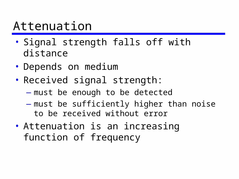
Attenuation• Signal strength falls off with distance• Depends on medium• Received signal strength:
—must be enough to be detected—must be sufficiently higher than noise to be
received without error
• Attenuation is an increasing function of frequency
Delay Distortion• Only in guided media• Propagation velocity varies with frequency
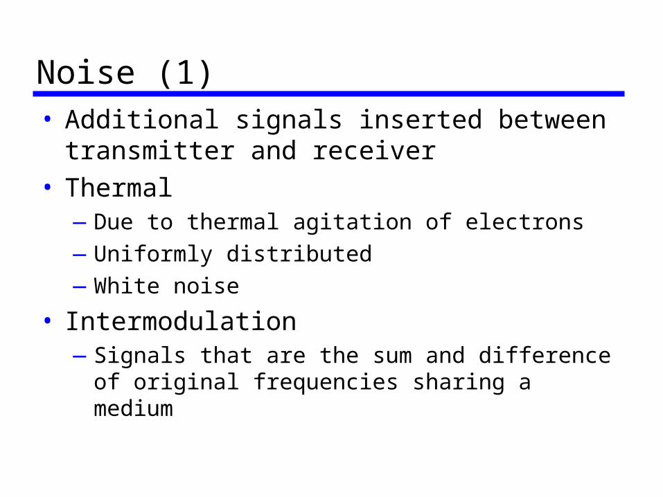
Noise (1)• Additional signals inserted between
transmitter and receiver• Thermal
—Due to thermal agitation of electrons—Uniformly distributed—White noise
• Intermodulation—Signals that are the sum and difference of
original frequencies sharing a medium
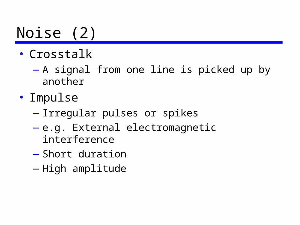
Noise (2)• Crosstalk
—A signal from one line is picked up by another
• Impulse—Irregular pulses or spikes—e.g. External electromagnetic interference—Short duration—High amplitude
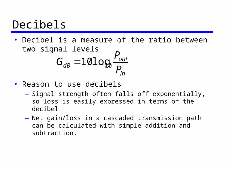
Decibels• Decibel is a measure of the ratio between two
signal levels
• Reason to use decibels—Signal strength often falls off exponentially, so loss is
easily expressed in terms of the decibel—Net gain/loss in a cascaded transmission path can be
calculated with simple addition and subtraction.
in
outdB P
PG 10log10
Channel Capacity• Data rate
—In bits per second—Rate at which data can be communicated
• Bandwidth—In cycles per second of Hertz—Constrained by transmitter and medium
Nyquist Bandwidth• If rate of signal transmission is 2B then
signal with frequencies no greater than B is sufficient to carry signal rate
• Given bandwidth B, highest signal rate is 2B
• Given binary signal, data rate supported by B Hz is 2B bps
• Can be increased by using M signal levels
• C= 2B log2M
• Noise-free channel
Shannon Capacity Formula• Consider data rate, noise and error rate• Faster data rate shortens each bit so burst
of noise affects more bits—At given noise level, high data rate means
higher error rate
• Signal to noise ratio (SNR) (in decibels)
• SNRdb=10 log10 (signal/noise)
• Capacity C=B log2(1+SNR)
• This is error free capacity
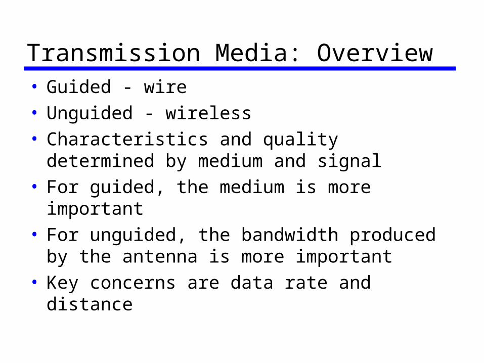
Transmission Media: Overview• Guided - wire• Unguided - wireless• Characteristics and quality determined by
medium and signal• For guided, the medium is more important• For unguided, the bandwidth produced by
the antenna is more important• Key concerns are data rate and distance
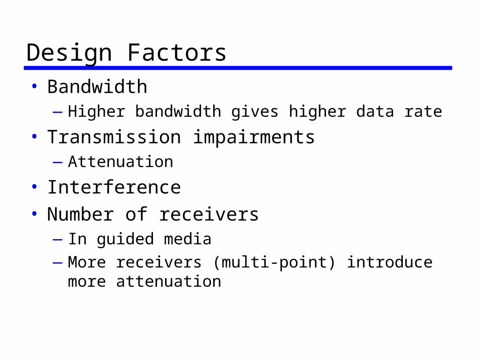
Design Factors• Bandwidth
—Higher bandwidth gives higher data rate
• Transmission impairments—Attenuation
• Interference• Number of receivers
—In guided media—More receivers (multi-point) introduce more
attenuation
Guided Transmission Media• Twisted Pair• Coaxial cable• Optical fiber
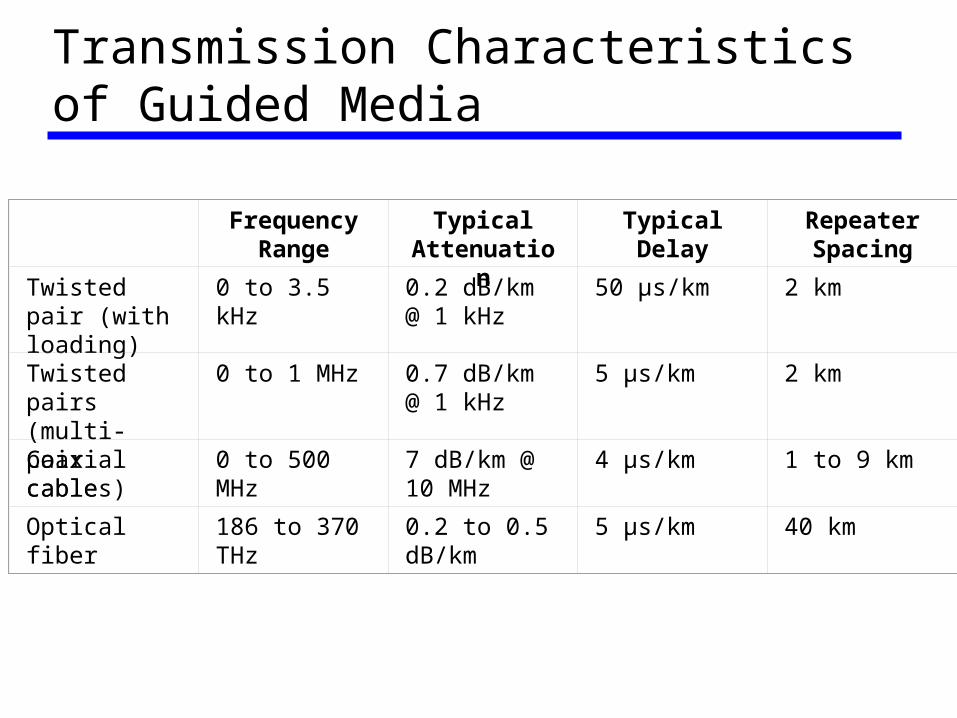
Transmission Characteristics of Guided Media
Frequency Range
Typical Attenuatio
n
Typical Delay
Repeater Spacing
Twisted pair (with loading)
0 to 3.5 kHz 0.2 dB/km @ 1 kHz
50 µs/km 2 km
Twisted pairs (multi-pair cables)
0 to 1 MHz 0.7 dB/km @ 1 kHz
5 µs/km 2 km
Coaxial cable
0 to 500 MHz
7 dB/km @ 10 MHz
4 µs/km 1 to 9 km
Optical fiber 186 to 370 THz
0.2 to 0.5 dB/km
5 µs/km 40 km
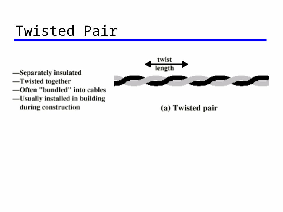
Twisted Pair
Twisted Pair - Applications• Most common medium• Telephone network
—Between house and local exchange (subscriber loop)
• Within buildings—To private branch exchange (PBX)
• For local area networks (LAN)—10Mbps or 100Mbps
Twisted Pair - Pros and Cons• Cheap• Easy to work with• Low data rate• Short range
Twisted Pair - Transmission Characteristics• Analog
—Amplifiers every 5km to 6km
• Digital—Use either analog or digital signals—repeater every 2km or 3km
• Limited distance• Limited bandwidth (1MHz)• Limited data rate (100MHz)• Susceptible to interference and noise
Unshielded and Shielded TP• Unshielded Twisted Pair (UTP)
—Ordinary telephone wire—Cheapest—Easiest to install—Suffers from external EM interference
• Shielded Twisted Pair (STP)—Metal braid or sheathing that reduces
interference—More expensive—Harder to handle (thick, heavy)
UTP Categories• Cat 3
—up to 16MHz—Voice grade found in most offices—Twist length of 7.5 cm to 10 cm
• Cat 4—up to 20 MHz
• Cat 5—up to 100MHz—Commonly pre-installed in new office buildings—Twist length 0.6 cm to 0.85 cm
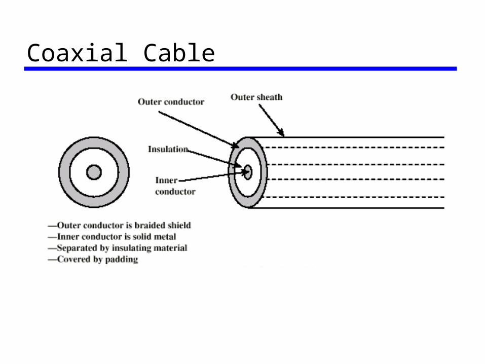
Coaxial Cable
Coaxial Cable Applications• Most versatile medium• Television distribution
—Ariel to TV—Cable TV
• Long distance telephone transmission—Can carry 10,000 voice calls simultaneously—Being replaced by fiber optic
• Short distance computer systems links• Local area networks
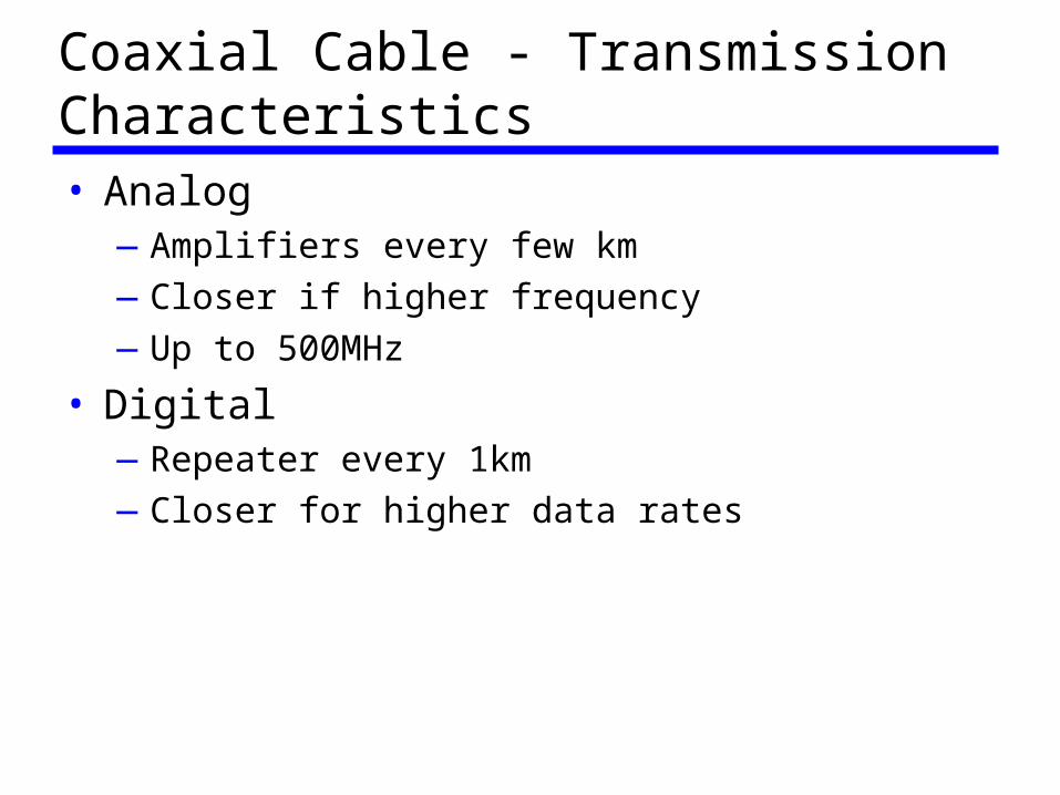
Coaxial Cable - Transmission Characteristics• Analog
—Amplifiers every few km—Closer if higher frequency—Up to 500MHz
• Digital—Repeater every 1km—Closer for higher data rates
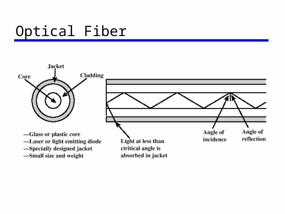
Optical Fiber
Optical Fiber - Benefits• Greater capacity
—Data rates of hundreds of Gbps
• Smaller size & weight• Lower attenuation• Electromagnetic isolation• Greater repeater spacing
—10s of km at least
Optical Fiber - Applications• Long-haul trunks• Metropolitan trunks• Rural exchange trunks• Subscriber loops• LANs
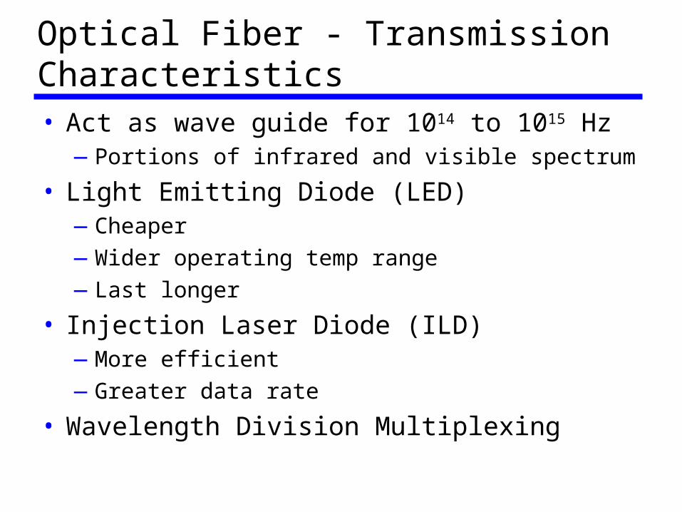
Optical Fiber - Transmission Characteristics• Act as wave guide for 1014 to 1015 Hz
—Portions of infrared and visible spectrum
• Light Emitting Diode (LED)—Cheaper—Wider operating temp range—Last longer
• Injection Laser Diode (ILD)—More efficient—Greater data rate
• Wavelength Division Multiplexing
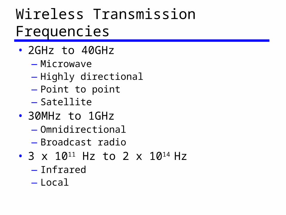
Wireless Transmission Frequencies• 2GHz to 40GHz
—Microwave—Highly directional—Point to point—Satellite
• 30MHz to 1GHz—Omnidirectional—Broadcast radio
• 3 x 10¹¹ Hz to 2 x 10¹⁴ Hz—Infrared—Local
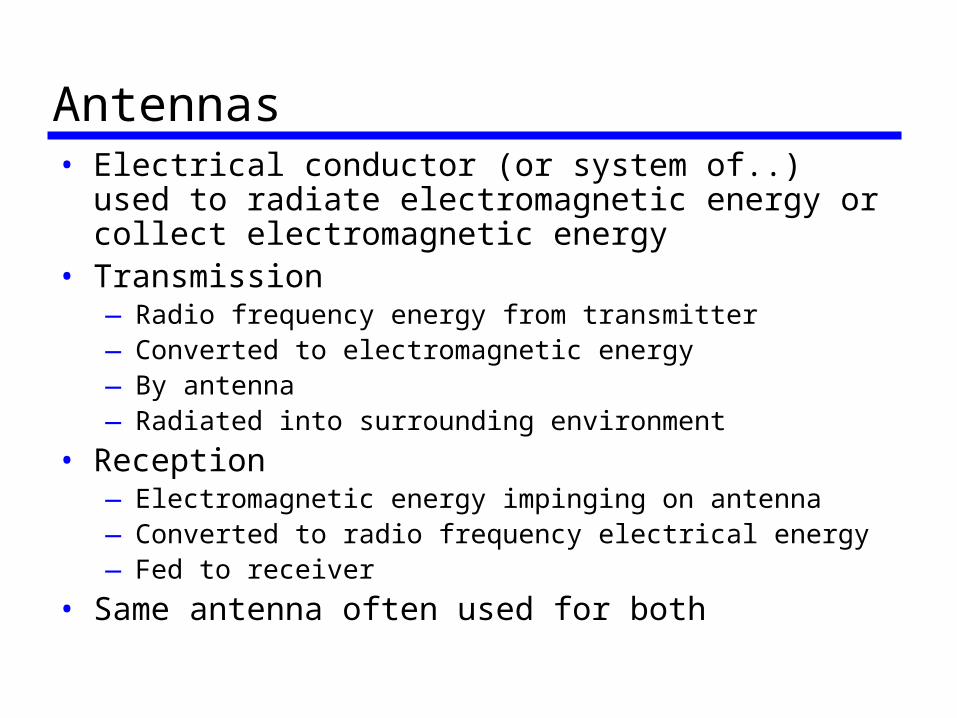
Antennas• Electrical conductor (or system of..) used to
radiate electromagnetic energy or collect electromagnetic energy
• Transmission—Radio frequency energy from transmitter—Converted to electromagnetic energy—By antenna—Radiated into surrounding environment
• Reception—Electromagnetic energy impinging on antenna—Converted to radio frequency electrical energy—Fed to receiver
• Same antenna often used for both
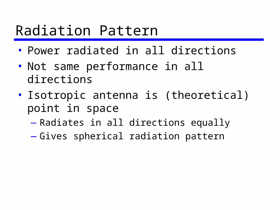
Radiation Pattern• Power radiated in all directions• Not same performance in all directions• Isotropic antenna is (theoretical) point in
space—Radiates in all directions equally—Gives spherical radiation pattern
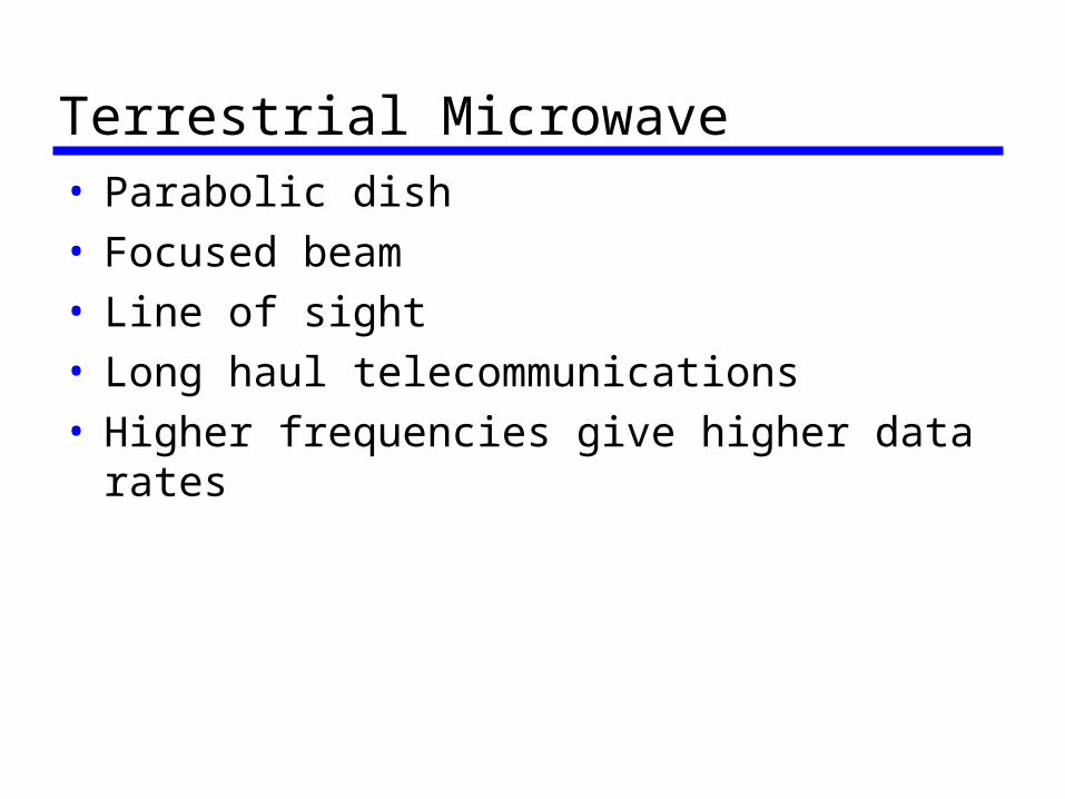
Terrestrial Microwave• Parabolic dish• Focused beam• Line of sight• Long haul telecommunications• Higher frequencies give higher data rates
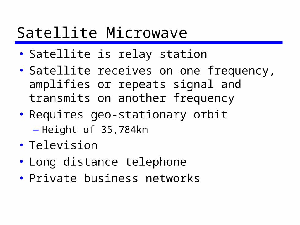
Satellite Microwave• Satellite is relay station• Satellite receives on one frequency,
amplifies or repeats signal and transmits on another frequency
• Requires geo-stationary orbit—Height of 35,784km
• Television• Long distance telephone• Private business networks
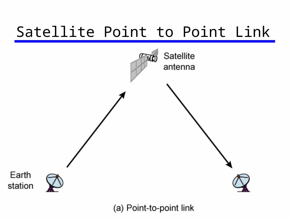
Satellite Point to Point Link
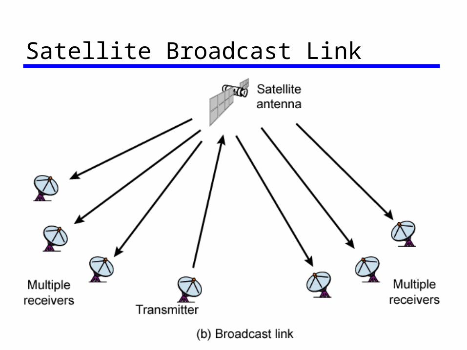
Satellite Broadcast Link
Broadcast Radio• Omnidirectional• FM radio• UHF and VHF television• Line of sight • Suffers from multipath interference
—Reflections
Infrared• Modulate noncoherent infrared light• Line of sight (or reflection)• Blocked by walls• e.g. TV remote control, IRD port