ecpri transport network v1 - cpri.info · cpri 4 ecpri transport network v1.2 (2018-06-25) 1 2....
TRANSCRIPT
eCPRI Transport Network V1.2 (2018-06-25)
Requirements Specification
Common Public Radio Interface: Requirements for the eCPRI Transport Network
The eCPRI Transport Network Requirements Specification has been developed by Ericsson AB, Huawei Technologies Co. Ltd, NEC Corporation and Nokia (the “Parties”) and may be updated from time to time. Further information about this requirements document and the latest version may be found at http://www.cpri.info. BY USING THE REQUIREMENTS FOR THE ECPRI TRANSPORT NETWORK SPECIFICATION, YOU ACCEPT THE “Interface Specification Download Terms and Conditions” FOUND AT http://www.cpri.info/spec.html. IN ORDER TO AVOID ANY DOUBT, BY DOWNLOADING AND/OR USING THE REQUIREMENTS FOR THE ECPRI TRANSPORT NETWORK SPECIFICATION NO EXPRESS OR IMPLIED LICENSE AND/OR ANY OTHER RIGHTS WHATSOEVER ARE GRANTED FROM ANYBODY. © 2018 Ericsson AB, Huawei Technologies Co. Ltd, NEC Corporation and Nokia.

CPRI
eCPRI Transport Network V1.2 (2018-06-25) 2
Table of Contents 1
1. Introduction ................................................................................................................. 3 2
2. Transport Network Terminology and Services ......................................................... 4 3
2.1. User Network Interface ................................................................................. 4 4
2.2. Transport Connection ................................................................................... 4 5
2.3. EVC Service Attributes ................................................................................. 5 6
2.3.1. One-way Frame Delay Performance ................................................. 5 7
2.3.2. One-way Frame Loss Ratio Performance .......................................... 5 8
2.4. EVC per UNI Service Attributes .................................................................... 5 9
3. Traffic Characterization .............................................................................................. 6 10
3.1. Generic traffic ................................................................................................ 6 11
3.2. Constant Bitrate traffic ................................................................................. 6 12
3.3. ON/OFF traffic ............................................................................................... 7 13
4. Requirements .............................................................................................................. 8 14
4.1. Per flow requirements................................................................................... 8 15
4.1.1. Split E and splits ID, IID, IU ............................................................... 8 16
4.2. Timing accuracy requirements .................................................................... 8 17
4.3. Phase noise and MTIE requirements ......................................................... 11 18
4.3.1. Phase noise characteristic at UNI .................................................... 11 19
4.3.2. MTIE mask at UNI ........................................................................... 11 20
4.4. In-order delivery .......................................................................................... 11 21
5. Annex A: Service Agreement considerations ......................................................... 12 22
6. List of Abbreviations ................................................................................................ 13 23
7. References ................................................................................................................ 14 24
8. History ....................................................................................................................... 15 25 26
CPRI
eCPRI Transport Network V1.2 (2018-06-25) 3
1. Introduction 1
The Common Public Radio Interface (CPRI) is an industry cooperation aimed at defining publicly available 2 specifications for the key internal interface of radio base stations, such as eCPRI connecting the eCPRI 3 Radio Equipment Control (eREC) and the eCPRI Radio Equipment (eRE) via a so-called fronthaul transport 4 network. The parties cooperating to define the specification are Ericsson AB, Huawei Technologies Co. Ltd, 5 NEC Corporation and Nokia. 6
The eCPRI Interface Specification [1] can be supported by Ethernet-switched or IP-routed fronthaul 7 networks, or similar types of transport networks. This specification describes the requirements that the 8 packet switched transport network must fulfill in order to support eCPRI services. 9
10
Scope of Specification: 11
This specification defines the details necessary to qualify and quantify the requirements on the underlying 12 transport network needed by the eCPRI layers to provide its services to the application. 13
14
eCPRI Radio Equipment Control (eREC)
eCPRI
specific
User Plane Sync C&M
eCPRI Radio Equipment (eRE)
Transport Network Layer
Standard
Protocols
SAPU SAPS SAPCM
eCPRI
specific
User Plane Sync C&M
Transport Network Layer
Standard
Protocols
SAPU SAPS SAPCM
Transport Network
Transport Network Interface Transport Network Interface
Scope of this specification
15
Figure 1 Scope definition 16
Equipment of independent vendors can share a common network. Thus, there must be no dependencies 17 (explicit or implied) between equipment of different vendors that use the same transport network. The details 18 of the network implementation shall be separated from the details of its users, i.e., the eCPRI equipment, by 19 means of a Transport Network Interface. This specification provides the eCPRI requirements to enable such 20 separation. 21
The packet switched transport network requirements to support eCPRI are independent of the technology 22 used by a given packet transport network supporting eCPRI, i.e., the same requirements apply to Ethernet or 23 IP transport networks. This document refers to the Carrier Ethernet services specified by the MEF Forum, 24 especially the Ethernet Service Attributes defined in [2]. However, Ethernet transport services are only 25 shown as an example, which are applicable, e.g., to Ethernet-based transport networks. The requirements 26 (and corresponding definitions) described in this document are equally applicable to other packet transport 27 networks based on different transport technologies (e.g., MPLS or IP) that can provide transport services 28 similar to the MEF transport services. 29
In MEF terminology, the Service Provider is the organization providing Ethernet Service(s) and the Transport 30 Network illustrated in Figure 1 is a network from a Service Provider or network Operator supporting the MEF 31 service and architecture models. The Subscriber is the organization purchasing and/or using Ethernet 32 Services, i.e., the eRE and eREC illustrated in Figure 1 belong to a Subscriber of transport service(s). The 33 technical specification of the service level being offered by the Service Provider to the Subscriber is referred 34 to as Service Level Specification (SLS). 35
CPRI
eCPRI Transport Network V1.2 (2018-06-25) 4
2. Transport Network Terminology and Services 1
This section describes terminology, services, service attributes, etc. that are widely used for transport 2 networks. Although, this section largely refers to the terminology used by the MEF Forum, neither the 3 transport network nor the service provided is limited to Ethernet, other technologies and services, e.g., IP 4
can also be used.1 5
2.1. User Network Interface 6
The User Network Interface (UNI) is the physical demarcation point between the responsibility of the Service 7 Provider and the responsibility of the Subscriber (section 7 in [2]). Figure 2 illustrates UNIs between eCPRI 8 equipment (eRE/eREC) and a transport network. It may contain one or more physical termination points (e.g., 9 Ethernet physical interfaces, see section 9.4 in [2]). Usually all physical termination points of an eCPRI unit 10 are part of the same UNI. 11
eREC eRETransport Network
UNI UNI 12
Figure 2 UNI between a eRE/eREC and a transport network 13
Note that the equipment on the Subscriber side of the UNI, i.e., eRE and eREC are referred to as Customer 14 Edge (CE) in [2]. 15
2.2. Transport Connection 16
The connection is the key component of the service(s) provided by a transport network. 17
A fundamental aspect of Ethernet Services is the Ethernet Virtual Connection (EVC). An EVC is an 18 association of two or more UNIs. The UNIs associated by an EVC are said to be “in the EVC”. A given UNI 19 can support more than one EVC (See section 8 in [2]). Service Frames are transmitted via a MEF UNI, 20 where a Service Frame is from the first bit of the Destination MAC Address through the last bit of the Frame 21 Check Sequence of an IEEE 802.3 Packet ([2]). 22
1 The definition of IP Services is an ongoing work at MEF

CPRI
eCPRI Transport Network V1.2 (2018-06-25) 5
eREC eRETransport Network
UNI UNI
EVC
1
Figure 3 Example of EVC and its relation to the UNI 2
Note that the same packet format is used at each UNI belonging to a particular service provided by a 3 transport network. For instance, Ethernet Service Frame on each UNI in the case of an Ethernet service. 4 Alternatively, it can be e.g., IP packet at each UNI. 5
UNI Service Attributes are described in section 9 in [2]. 6
2.3. EVC Service Attributes 7
A transport service is specified using service attributes. Each of these attributes defines specific information 8 about the service that is agreed between a Subscriber and a Provider of the transport service. It is outside 9 the scope of this document how an agreement is established between a Subscriber and a Provider. See 10 section 5 for examples of how an agreement can be established. 11
EVC Service Attributes are described in section 8 in [2] and EVC per UNI Service Attributes are described in 12 section 10 in [2]. 13
Two EVC Performance Service Attributes are of special interest of the current release of this document. 14
2.3.1. One-way Frame Delay Performance 15
The One-way Frame Delay for an egress Service Frame in the EVC is defined as the time elapsed from the 16 transmission at the ingress UNI of the first bit of the corresponding Service Frame until the reception of the 17 last bit of the Service Frame at the paired UNI (section 8.8.1 in [2]). 18
Note that this definition of Frame Delay for a Service Frame is the one-way delay that includes the delays 19 encountered as a result of transmission of the Service Frame across the ingress and egress UNIs as well as 20 those introduced by the transport network. 21
The One-way Frame Delay Performance is described in section 8.8.1 of [2]. Only the maximum value of the 22 One-way Frame Delay Performance is of special interest of the current release of this document. 23
2.3.2. One-way Frame Loss Ratio Performance 24
The One-way Frame Loss Ratio Performance is described in section 8.8.3 of [2]. 25
2.4. EVC per UNI Service Attributes 26
The Class of Service (CoS) Identifier for Data Service Frames is an EVC per UNI Service Attribute that is of 27 special interest for this document. The following Class of Service identification methods are of interest 28 among the ones described in 10.2.1 of [2]: 29
• Class of Service Identifier based on the EVC (see section 10.2.1.1 of [2]). 30
• Class of Service Identifier based on the Priority Code Point Field (see section 10.2.1.2 of [2]). 31
• Class of Service Identifier based on Internet Protocol (see section 10.2.1.3 of [2]). 32

CPRI
eCPRI Transport Network V1.2 (2018-06-25) 6
3. Traffic Characterization 1
This section provides a general model based on MEF’s Generic Token Bucket Algorithm (GTBA) and some 2 examples of simple traffic models. A list of performance service attributes is provided for each model as a 3 blueprint for service agreement terms between a Subscriber and a Provider. Neither the set of models 4 included nor each model individually is exhaustive or a perfect characterization of the real-life traffic covering 5 all cases. 6
In the following sub-sections, physical bit rate refers to the physical line bit rate of the transmitting UNI. 7
3.1. Generic traffic 8
The Generic traffic profile corresponds to the Generic Token Bucket Algorithm (GTBA) as described in 9 [12].The performance service attributes metrics for the Generic traffic profile, as defined in section 12.1 of [2] 10 are: 11
• Committed Information Rate (CIR) 12
• Maximum Committed Information Rate (CIRmax) 13
• Committed Burst Size (CBS) 14
• Excess Information Rate (EIR) 15
• Maximum Excess Information Rate (EIRmax) 16
• Excess Burst Size (EBS) 17
Bit Rate
Time
Long-Term Average Bit Rate
Short-Term Average Bit Rate
Physical Bit Rate
CIR
18
Figure 4 An illustration of data traffic behavior over time 19
3.2. Constant Bitrate traffic 20
The Constant Bitrate traffic represents a profile where traffic is transferred at an average constant bitrate: 21 CIR as defined in [2]. 22
Packet transmissions are separated by tIP = SP/ CIR, where SP is the packet size. 23
The performance service attribute metrics for the Constant Bitrate traffic profile are: 24
• CIR 25
• Maximum packet size, corresponding to CBS (for compatibility with the section 3.1 Generic traffic) 26
CPRI
eCPRI Transport Network V1.2 (2018-06-25) 7
Bit Rate
Time
P1
tIP1
Physical Bit
Rate
CIR
tIP2
P2
SP1 SP2
1
Figure 5 Constant Bitrate traffic profile 2
3
3.3. ON/OFF traffic 4
The ON/OFF traffic profile represents a profile where traffic is transferred only during the so-called ON-period. 5 During the ON-period traffic is transferred at the physical bit rate. In contrast, during the so-called OFF-6 period no traffic is transferred at all. 7
ON-periods and OFF-periods are strictly alternating. The additional performance service attributes metrics 8 for the ON/OFF traffic profile are: 9
• ON-period maximum time duration. 10
• ON/OFF-period minimum time duration. 11
The ON-period is defined as the time during which all packets are transferred within an ON/OFF period. The 12 ON-period maximum time duration corresponds to CBS / ‘Physical Bit Rate’. 13
The ON/OFF-period time duration is defined as the time elapsed between the start of two consecutive ON-14 periods. The ON/OFF-period minimum time duration corresponds to CBS/CIR. 15
Bit Rate
ON OFFTime
ON-period
ON/OFF-period
Physical Bit
Rate
16
Figure 6 ON-period and ON/OFF-period 17
CPRI
eCPRI Transport Network V1.2 (2018-06-25) 8
4. Requirements 1
4.1. Per flow requirements 2
4.1.1. Split E and splits ID, IID, IU 3
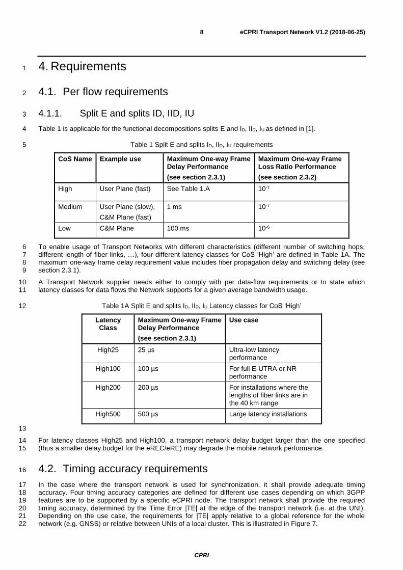
Table 1 is applicable for the functional decompositions splits E and ID, IID, IU as defined in [1]. 4
Table 1 Split E and splits ID, IID, IU requirements 5
CoS Name Example use Maximum One-way Frame Delay Performance
(see section 2.3.1)
Maximum One-way Frame Loss Ratio Performance
(see section 2.3.2)
High User Plane (fast) See Table 1.A 10-7
Medium User Plane (slow),
C&M Plane (fast)
1 ms 10-7
Low C&M Plane 100 ms 10-6
To enable usage of Transport Networks with different characteristics (different number of switching hops, 6 different length of fiber links, …), four different latency classes for CoS ‘High’ are defined in Table 1A. The 7 maximum one-way frame delay requirement value includes fiber propagation delay and switching delay (see 8 section 2.3.1). 9
A Transport Network supplier needs either to comply with per data-flow requirements or to state which 10 latency classes for data flows the Network supports for a given average bandwidth usage. 11
Table 1A Split E and splits ID, IID, IU Latency classes for CoS ‘High’ 12
Latency Class
Maximum One-way Frame Delay Performance
(see section 2.3.1)
Use case
High25 25 µs Ultra-low latency performance
High100 100 µs For full E-UTRA or NR performance
High200 200 µs For installations where the lengths of fiber links are in the 40 km range
High500 500 µs Large latency installations
13
For latency classes High25 and High100, a transport network delay budget larger than the one specified 14 (thus a smaller delay budget for the eREC/eRE) may degrade the mobile network performance. 15
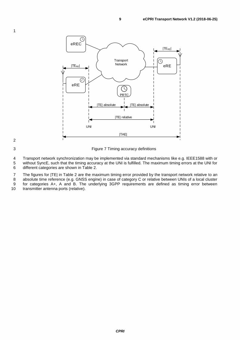
4.2. Timing accuracy requirements 16
In the case where the transport network is used for synchronization, it shall provide adequate timing 17 accuracy. Four timing accuracy categories are defined for different use cases depending on which 3GPP 18 features are to be supported by a specific eCPRI node. The transport network shall provide the required 19 timing accuracy, determined by the Time Error |TE| at the edge of the transport network (i.e. at the UNI). 20 Depending on the use case, the requirements for |TE| apply relative to a global reference for the whole 21 network (e.g. GNSS) or relative between UNIs of a local cluster. This is illustrated in Figure 7. 22
CPRI
eCPRI Transport Network V1.2 (2018-06-25) 9
1
TransportNetwork
eRE
eREC
eRE
|TERE|
|TE| relative
|TERE|
UNI
|TAE|
UNI
PRTC
|TE| absolute |TE| absolute
2
Figure 7 Timing accuracy definitions 3
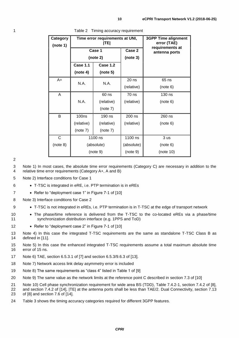
Transport network synchronization may be implemented via standard mechanisms like e.g. IEEE1588 with or 4 without SyncE, such that the timing accuracy at the UNI is fulfilled. The maximum timing errors at the UNI for 5 different categories are shown in Table 2. 6
The figures for |TE| in Table 2 are the maximum timing error provided by the transport network relative to an 7 absolute time reference (e.g. GNSS engine) in case of category C or relative between UNIs of a local cluster 8 for categories A+, A and B. The underlying 3GPP requirements are defined as timing error between 9 transmitter antenna ports (relative). 10
CPRI
eCPRI Transport Network V1.2 (2018-06-25) 10
Table 2 Timing accuracy requirement 1
Category
(note 1)
Time error requirements at UNI, |TE|
3GPP Time alignment error (TAE)
requirements at antenna ports Case 1
(note 2)
Case 2
(note 3)
Case 1.1
(note 4)
Case 1.2
(note 5)
A+ N.A. N.A.
20 ns
(relative)
65 ns
(note 6)
A
N.A.
60 ns
(relative)
(note 7)
70 ns
(relative)
130 ns
(note 6)
B 100ns
(relative)
(note 7)
190 ns
(relative)
(note 7)
200 ns
(relative)
260 ns
(note 6)
C
(note 8)
1100 ns
(absolute)
(note 9)
1100 ns
(absolute)
(note 9)
3 us
(note 6)
(note 10)
2
Note 1) In most cases, the absolute time error requirements (Category C) are necessary in addition to the 3 relative time error requirements (Category A+, A and B) 4
Note 2) Interface conditions for Case 1 5
• T-TSC is integrated in eRE, i.e. PTP termination is in eREs 6
• Refer to “deployment case 1” in Figure 7-1 of [10] 7
Note 3) Interface conditions for Case 2 8
• T-TSC is not integrated in eREs, i.e. PTP termination is in T-TSC at the edge of transport network 9
• The phase/time reference is delivered from the T-TSC to the co-located eREs via a phase/time 10 synchronization distribution interface (e.g. 1PPS and ToD) 11
• Refer to “deployment case 2” in Figure 7-1 of [10] 12
Note 4) In this case the integrated T-TSC requirements are the same as standalone T-TSC Class B as 13 defined in [11]. 14
Note 5) In this case the enhanced integrated T-TSC requirements assume a total maximum absolute time 15 error of 15 ns. 16
Note 6) TAE, section 6.5.3.1 of [7] and section 6.5.3/9.6.3 of [13]. 17
Note 7) Network access link delay asymmetry error is included 18
Note 8) The same requirements as “class 4” listed in Table 1 of [9] 19
Note 9) The same value as the network limits at the reference point C described in section 7.3 of [10] 20
Note 10) Cell phase synchronization requirement for wide area BS (TDD), Table 7.4.2-1, section 7.4.2 of [8], 21 and section 7.4.2 of [14], |TE| at the antenna ports shall be less than TAE/2. Dual Connectivity, section 7.13 22 of [8] and section 7.6 of [14]. 23
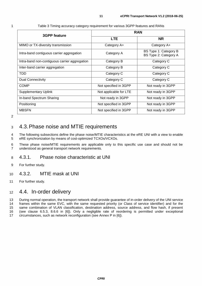
Table 3 shows the timing accuracy categories required for different 3GPP features. 24
CPRI
eCPRI Transport Network V1.2 (2018-06-25) 11
Table 3 Timing accuracy category requirement for various 3GPP features and RANs 1
3GPP feature RAN
LTE NR
MIMO or TX-diversity transmission Category A+ Category A+
Intra-band contiguous carrier aggregation Category A BS Type 1: Category B BS Type 2: Category A
Intra-band non-contiguous carrier aggregation Category B Category C
Inter-band carrier aggregation Category B Category C
TDD Category C Category C
Dual Connectivity Category C Category C
COMP Not specified in 3GPP Not ready in 3GPP
Supplementary Uplink Not applicable for LTE Not ready in 3GPP
In-band Spectrum Sharing Not ready in 3GPP Not ready in 3GPP
Positioning Not specified in 3GPP Not ready in 3GPP
MBSFN Not specified in 3GPP Not ready in 3GPP
2
4.3. Phase noise and MTIE requirements 3
The following subsections define the phase noise/MTIE characteristics at the eRE UNI with a view to enable 4 eRE synchronization by means of cost-optimized TCXOs/VCXOs. 5
These phase noise/MTIE requirements are applicable only to this specific use case and should not be 6 understood as general transport network requirements. 7
4.3.1. Phase noise characteristic at UNI 8
For further study. 9
4.3.2. MTIE mask at UNI 10
For further study. 11
4.4. In-order delivery 12
During normal operation, the transport network shall provide guarantee of in-order delivery of the UNI service 13 frames within the same EVC, with the same requested priority (or Class of service identifier) and for the 14 same combination of VLAN classification, destination address, source address, and flow hash, if present 15 (see clause 6.5.3, 8.6.6 in [6]). Only a negligible rate of reordering is permitted under exceptional 16 circumstances, such as network reconfiguration (see Annex P in [6]). 17
CPRI
eCPRI Transport Network V1.2 (2018-06-25) 12
5. Annex A: Service Agreement considerations 1
This is a non-exhaustive list of how an agreement between a Subscriber and a Provider on the attributes of a 2 network service can be established: 3
• The Provider mandates a value for each attribute. 4
• The Subscriber selects from a set of options specified by the Provider. 5
• The Subscriber requests a value for each attribute, and the Provider indicates whether they can 6 provide the service based on these attributes. 7
• The user and the Provider negotiate to reach a mutually acceptable value for all parameters. 8
An agreement can be established manually (e.g. on a piece of paper) or automatically, i.e. through API 9 provided by the network Provider. 10
CPRI
eCPRI Transport Network V1.2 (2018-06-25) 13
6. List of Abbreviations 1
3GPP 3rd Generation Partnership Project 2
CBR Constant Bit Rate 3
CBS Committed Burst Size 4
CE Customer Edge 5
CIR Committed Information Rate 6
CoS Class of Service 7
CPRI Common Public Radio Interface 8
EBS Excess Burst Size 9
EIR Excess Information Rate 10
eRE eCPRI Radio Equipment 11
eREC eCPRI Radio Equipment Control 12
EVC Ethernet Virtual Connection 13
GNSS Global Navigation Satellite System 14
GTBA Generic Token Bucket Algorithm 15
IP Internet Protocol 16
IPv4 Internet Protocol version 4 17
IPv6 Internet Protocol version 6 18
LTE Long Term Evolution 19
MAC Media Access Control 20
MEF Metro Ethernet Forum 21
MIMO Multiple Input Multiple Output 22
MTIE Maximum Time Interval Error 23
N/A Not Applicable 24
PPS Pulse Per Second 25
PRTC Primary Reference Time Clock 26
QoS Quality of Service 27
SLS Service Level Specification 28
SyncE Synchronous Ethernet 29
TAE Time Alignment Error 30
TCXO Temperature Compensated Crystal Oscillator 31
TDD Time Division Duplex 32
ToD Time of Day 33
T-TSC Telecom Time Slave clock 34
UNI User Network Interface 35
VCXO Voltage Controlled Crystal Oscillator 36
VLAN Virtual LAN 37
CPRI
eCPRI Transport Network V1.2 (2018-06-25) 14
7. References 1
[1] eCPRI Specification V1.0, Tech. Rep. Aug. 2017, http://www.cpri.info/ 2
[2] Technical Specification MEF 10.3 Ethernet Services Attributes Phase 3 October 2013 3
[3] IEEE Std 802.3-2015 IEEE, New York, USA, 3 December 2015 4
[4] RFC 791- INTERNET PROTOCOL, September 1981 5
[5] RFC 2460 - Internet Protocol, Version 6 (IPv6) Specification, December 1998 6
[6] IEEE Std. 802.1Q-2014 IEEE, New York, USA, 3 November 2014 7
[7] 3GPP TS36.104, “E-UTRA; Base Station (BS) radio transmission and reception”, V15.2.0 8
[8] 3GPP TS36.133, “E-UTRA; Requirements for support of radio resource management”, V15.2.0 9
[9] ITU-T G.8271, “Time and phase synchronization aspects of packet networks”, August 2017 10
[10] ITU-T G.8271.1, “Network limits for time synchronization in packet networks”, August 2013 11
[11] ITU-T G.8273.2, “Timing characteristics of telecom boundary clocks and telecom time slave”, 12 January 2017 13
[12] Technical Specification MEF 41 Generic Token Bucket Algorithm October 2013 14
[13] 3GPP TS38.104, “NR; Base Station (BS) radio transmission and reception”, V15.1.0 15
[14] 3GPP TS38.133, “NR; Requirements for support of radio resource management”, V15.1.0 16
CPRI
eCPRI Transport Network V1.2 (2018-06-25) 15
8. History 1
Version Date Description
D 0.1 2017-08-30 First Draft
V 1.0 2017-10-24 Summary of Section 2.4 updates:
• The whole section is updated.
• Section 2.4.1 is deleted.
• Section 2.4.1.1 is deleted.
• Section 2.4.1.2 is deleted.
• Section 2.4.1.3 is deleted. Section 3 added Summary of Section 4 updates: Section 4.2:
• Figure 4 is updated
• Case 1 sub-cases are added: Case 1.1 and Case 1.2
• Note 9 associated to sub-case 1.1 is added
• Note 10 associated to sub-case 1.2 is added
• Note 3 editorial correction: (“is” replaced by “are”)
• Note 8 precising link assymetry assumption is added.
• All TBD are replace by values or N.A. Section 4.3:
• New section 4.3 “Phase noise and MTIE requirements” is added
• “In-order delivery” is moved to 4.4 Summary of Section 6 updates:
• MTIE added
Summary of Section 7 updates:
• New reference:
[11] ITU-T G.8273.2], “Timing characteristics of telecom boundary clocks and telecom time slave
[12] Technical Specification MEF 41 Generic Token Bucket Algorithm October 2013
Summary of Section 8 updates:
• Section 2.4 updates are refered
• Section 4.2 updates are refered
• Section 4.3 “Phase noise and MTIE requirements” section insertion is refered and previous section 4.3 “In-Order delivery” move is refered.
V 1.1 2018-01-10 Minor editorial changes.
CPRI
eCPRI Transport Network V1.2 (2018-06-25) 16
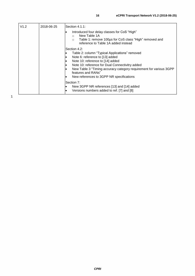
V1.2 2018-06-25 Section 4.1.1:
• Introduced four delay classes for CoS “High” o New Table 1A o Table 1: remove 100µs for CoS class “High” removed and
reference to Table 1A added instead
Section 4.2:
• Table 2: column “Typical Applications” removed
• Note 6: reference to [13] added
• Note 10: reference to [14] added
• Note 10: reference for Dual Connectivitry added
• New Table 3 “Timing accuracy category requirement for various 3GPP features and RANs”
• New references to 3GPP NR specifications
Section 7:
• New 3GPP NR references [13] and [14] added
• Versions numbers added to ref. [7] and [8]
1