ecosystem digital ballast installation guide · · 2012-05-22control methods ... method require...
TRANSCRIPT

EEccooSSyysstteemmTTMM DDiiggiittaall BBaallllaasstt || IInnssttaallllaattiioonn GGuuiiddee

EcoSystemTM Ballast Installation Guide R

Contents
Before You Get Started: Important Information About EcoSystem BallastsWhat is EcoSystem? . . . . . . . . . . . . . . . . . . . . . . . . . . . . . . . . . . . . . . . . . . . . . . . . . . . . 2EcoSystem Ballasts . . . . . . . . . . . . . . . . . . . . . . . . . . . . . . . . . . . . . . . . . . . . . . . . . . . . . 2Lamp Types . . . . . . . . . . . . . . . . . . . . . . . . . . . . . . . . . . . . . . . . . . . . . . . . . . . . . . . . . . . 3
Seasoning New Lamps. . . . . . . . . . . . . . . . . . . . . . . . . . . . . . . . . . . . . . . . . . . . . . . . 3Rapid-Start Lamp Sockets . . . . . . . . . . . . . . . . . . . . . . . . . . . . . . . . . . . . . . . . . . . . . . . . 4
Why Rapid-Start Sockets Are Important . . . . . . . . . . . . . . . . . . . . . . . . . . . . . . . . . . . 4Ballast Wiring . . . . . . . . . . . . . . . . . . . . . . . . . . . . . . . . . . . . . . . . . . . . . . . . . . . . . . . . . . 5
Maximum Wire Lead Length. . . . . . . . . . . . . . . . . . . . . . . . . . . . . . . . . . . . . . . . . . . . 5Gauge Requirements . . . . . . . . . . . . . . . . . . . . . . . . . . . . . . . . . . . . . . . . . . . . . . . . . 5Separating Class 1 and Class 2 Wires . . . . . . . . . . . . . . . . . . . . . . . . . . . . . . . . . . . . 5
Ballast Temperature . . . . . . . . . . . . . . . . . . . . . . . . . . . . . . . . . . . . . . . . . . . . . . . . . . . . . 6Ambient Operating Temperature . . . . . . . . . . . . . . . . . . . . . . . . . . . . . . . . . . . . . . . . . 6Calibration Point Measurement Example. . . . . . . . . . . . . . . . . . . . . . . . . . . . . . . . . . . 6Tips for Controlling Ballast Temperature . . . . . . . . . . . . . . . . . . . . . . . . . . . . . . . . . . . 6Fixture Design. . . . . . . . . . . . . . . . . . . . . . . . . . . . . . . . . . . . . . . . . . . . . . . . . . . . . . . 6
Control Methods. . . . . . . . . . . . . . . . . . . . . . . . . . . . . . . . . . . . . . . . . . . . . . . . . . . . . . . . 7EcoSystem Bus . . . . . . . . . . . . . . . . . . . . . . . . . . . . . . . . . . . . . . . . . . . . . . . . . . . . . 7Standard 3-Wire Control . . . . . . . . . . . . . . . . . . . . . . . . . . . . . . . . . . . . . . . . . . . . . . . 7Digital Wallstations . . . . . . . . . . . . . . . . . . . . . . . . . . . . . . . . . . . . . . . . . . . . . . . . . . . 7Sensors . . . . . . . . . . . . . . . . . . . . . . . . . . . . . . . . . . . . . . . . . . . . . . . . . . . . . . . . . . . 8EcoSystem Bus Supply . . . . . . . . . . . . . . . . . . . . . . . . . . . . . . . . . . . . . . . . . . . . . . . 8
Step by Step: Installing and Wiring an EcoSystem Dimming BallastTypical Workflow. . . . . . . . . . . . . . . . . . . . . . . . . . . . . . . . . . . . . . . . . . . . . . . . . . . . . . . . 9Mounting the Ballast. . . . . . . . . . . . . . . . . . . . . . . . . . . . . . . . . . . . . . . . . . . . . . . . . . . . 10Ballast Dimensions . . . . . . . . . . . . . . . . . . . . . . . . . . . . . . . . . . . . . . . . . . . . . . . . . . . . . 11Wiring the Lamp Sockets . . . . . . . . . . . . . . . . . . . . . . . . . . . . . . . . . . . . . . . . . . . . . . . . 11
1-Lamp Socket Wiring . . . . . . . . . . . . . . . . . . . . . . . . . . . . . . . . . . . . . . . . . . . . . . . 122-Lamp Socket Wiring . . . . . . . . . . . . . . . . . . . . . . . . . . . . . . . . . . . . . . . . . . . . . . . 123-Lamp Socket Wiring . . . . . . . . . . . . . . . . . . . . . . . . . . . . . . . . . . . . . . . . . . . . . . . 12U-Bend Lamp Socket Wiring . . . . . . . . . . . . . . . . . . . . . . . . . . . . . . . . . . . . . . . . . . 12
Wiring the Ballast to the Lamp Sockets . . . . . . . . . . . . . . . . . . . . . . . . . . . . . . . . . . . . . 13Wiring to One Lamp . . . . . . . . . . . . . . . . . . . . . . . . . . . . . . . . . . . . . . . . . . . . . . . . . 13Wiring to Two Lamps . . . . . . . . . . . . . . . . . . . . . . . . . . . . . . . . . . . . . . . . . . . . . . . . 13Wiring to Three Lamps . . . . . . . . . . . . . . . . . . . . . . . . . . . . . . . . . . . . . . . . . . . . . . . 13
Connecting the Line Voltage. . . . . . . . . . . . . . . . . . . . . . . . . . . . . . . . . . . . . . . . . . . . . . 14Connecting the EcoSystem Bus . . . . . . . . . . . . . . . . . . . . . . . . . . . . . . . . . . . . . . . . . . . 15Connecting Sensors and Wallstations. . . . . . . . . . . . . . . . . . . . . . . . . . . . . . . . . . . . . . . 16Mounting the Lamps . . . . . . . . . . . . . . . . . . . . . . . . . . . . . . . . . . . . . . . . . . . . . . . . . . . 17Sample Mounted and Wired Ballasts . . . . . . . . . . . . . . . . . . . . . . . . . . . . . . . . . . . . . . . 17
Typical 2-Lamp Linear Fixture . . . . . . . . . . . . . . . . . . . . . . . . . . . . . . . . . . . . . . . . . . 17Typical 3-Lamp Linear Fixture . . . . . . . . . . . . . . . . . . . . . . . . . . . . . . . . . . . . . . . . . . 18
Testing the Ballast . . . . . . . . . . . . . . . . . . . . . . . . . . . . . . . . . . . . . . . . . . . . . . . . . . . . . 19
Ballast Warranty
Technical Support: +1.800.523.9466 – www.lutron.com/ecosystem R

EcoSystemTM Ballast Installation Guide R2
Before You Get Started:
Important Information AboutEcoSystemTM Ballasts
This section of the installation guide includes important topics that a fixture manufactureror an electrical contractor needs to know before installing and wiring an EcoSystemdimming ballast. Read this section carefully before proceeding to the installation stepsbeginning on page 9.
What is EcoSystem?
Lutron’s EcoSystem lighting network starts with one simple but essential buildingblock—the EcoSystem dimming ballast—which replaces the non-dim ballast in a fixture. Avariety of sensors or wallstations are connected directly to the ballast to create an efficientlighting control system. All of this can be accomplished on an individual ballast or up to 64ballasts connected together - allowing sensors to have single or multiple zone control.
EcoSystem Ballasts
EcoSystem ballasts are available for many voltages and lamp types, please consult Lutron.If a ballast is not available for direct control via the EcoSystem Bus, a standard Lutrondimming ballast can be connected using a Ballast Module.
EcoSystem Ballast Wiring Snapshot
EcoSystem ballasts require power, like non-dim ballasts, and also receive low voltagecontrol inputs from the EcoSystem Bus and sensors. Use this guide for ballast wiringdetails. A wiring summary is shown below:
1
+20V
DaylightOccIR
Common
Class 2 (#22 AW
G S
olid)
E2E1
Class 2
Bus
DHNEU
277 VoltSH
Wire Power (solid #18 - #16 AWG) hereEcoSystem Bus (solid #18 - #16 AWG)-2 low voltage wiresconnect up to 64EcoSystem ballaststogether. Wire busClass 1 or Class 2 here
Class 2 Sensors (solid #22AWG)-Connect an EcoSystem daylight sensor, occupantsensor, and wallstation or IR receiver here
Lamp Wires(solid #18 AWG)-2 wires for eachlamp socket

Technical Support: +1.800.523.9466 – www.lutron.com/ecosystem 3R
Seasoning New Lamps
Consult lamp manufacturer for lamp seasoning requirements prior to dimming.
To season lamps perform one of the following:
• Operate new lamps at full output continuously.
• Remove lamps from another (non-dimmed) area; re-install in dimming area.
• Use a seasoning station to build an inventory of properly seasoned lamps.
TT88//TT55 lliinneeaarr llaammppss aarree ssttrraaiigghhtt wwiitthhttwwoo ppiinnss aatt eeiitthheerr eenndd..
TT88 UU--bbeenndd llaammppss hhaavvee aa ““UU””sshhaappee aanndd ttwwoo ppiinnss aatt eeiitthheerr eenndd..
Lamp Types
EcoSystem T8 ballasts may be used with either linear or U-bend T8 lamps. T5 ballastsmay only be used with linear T5 lamps.

Why Rapid-Start Sockets Are Important
Dimming ballasts must access both lamp pins to heat the lamp filaments. Without heating,the lamp will fail prematurely. Good lamp pin-to-socket contact and correct wiring arerequired to produce flicker-free dimming and to ensure long lamp life.
EcoSystemTM Ballast Installation Guide R4
BBaacckk MMUUSSTTnnoott bbee fflleexxiibblleemmaatteerriiaall..
AA jjuummppeerr mmaayy hhaavveebbeeeenn iinnssttaalllleedd ffoorriinnssttaanntt--ssttaarrttaapppplliiccaattiioonnss.. TThhiissjjuummppeerr mmuusstt bbeerreemmoovveedd..
TT88//TT55 rraappiidd--ssttaarrtt ssoocckkeett
RRaappiidd--ssttaarrtt((sslliiddee--iinn vvaarriieettyy))
RRaappiidd--ssttaarrtt((rroottaarryy lloocckkiinngg vvaarriieettyy))
RRaappiidd--ssttaarrtt((kknniiffee--eeddggee vvaarriieettyy))
IInnssttaanntt--ssttaarrtt((ddoo nnoott uussee))
FFlluuoorreesscceenntt llaammpp
FFiillaammeenntt
FFllooww ooff eelleeccttrriicciittyy ffoorr ffiillaammeenntt hheeaattiinngg
Rapid-Start Lamp Sockets
EcoSystem ballasts require rapid-start lamp sockets. Lutron recommends sockets thatmeet IEC 60400. Lutron recommends a rotary locking variety, with metal contacts thatmake firm contact with the lamp pins. The slide-in or knife-edge varieties can also beused.
Backing material of the socket should be the same material as the rest of the socket body,and should not deform with over-insertion of wires or lamp changes. For detailedspecifications on sockets, refer to Application Note #122: Lampholders and LampholderInstallation for Fluorescent Dimming.
CAUTION:UUssiinngg EEccooSSyysstteemm bbaallllaassttss wwiitthh iinnssttaanntt--ssttaarrtt ssoocckkeettss mmaayy ddaammaaggee tthhee bbaallllaassttss..

Technical Support: +1.800.523.9466 – www.lutron.com/ecosystem 5R
Ballast Wiring
Maximum Wire Lead Length
Lead lengths from a ballast to the sockets must not exceed 7 ft (2.1 m). Exceeding themaximum lead length may cause lamp flicker, improper starting, and/or reduced lamp life.
Gauge Requirements
Terminal blocks on the ballast are poke-in wire trap connectors that accept the followingwire gauges:
• Mains Wiring, EcoSystem Bus, Lamp Wiring: #18 _ #16 AWG (1.02 _ 1.29 mm) solid
• Class 2 Sensor Wires: #22 AWG (0.635 mm) Solid
NOTE: Ballast terminals hold only one solid wire. In most cases, a wire connectionto the distribution bus or EcoSystem Bus is required.
Separating Class 1 and Class 2 Wires
The EcoSystem Bus may be connected to the ballast using Class 1 or Class 2 wiringmethods. Sensors and wallstations must be wired Class 2. When using both Class 1 andClass 2 wiring methods, it is essential to Class 2 wires separate from Mains and Class 1wires by at least 0.25" (6.35 mm). Consult all applicable national and local codes for wiringrestrictions.
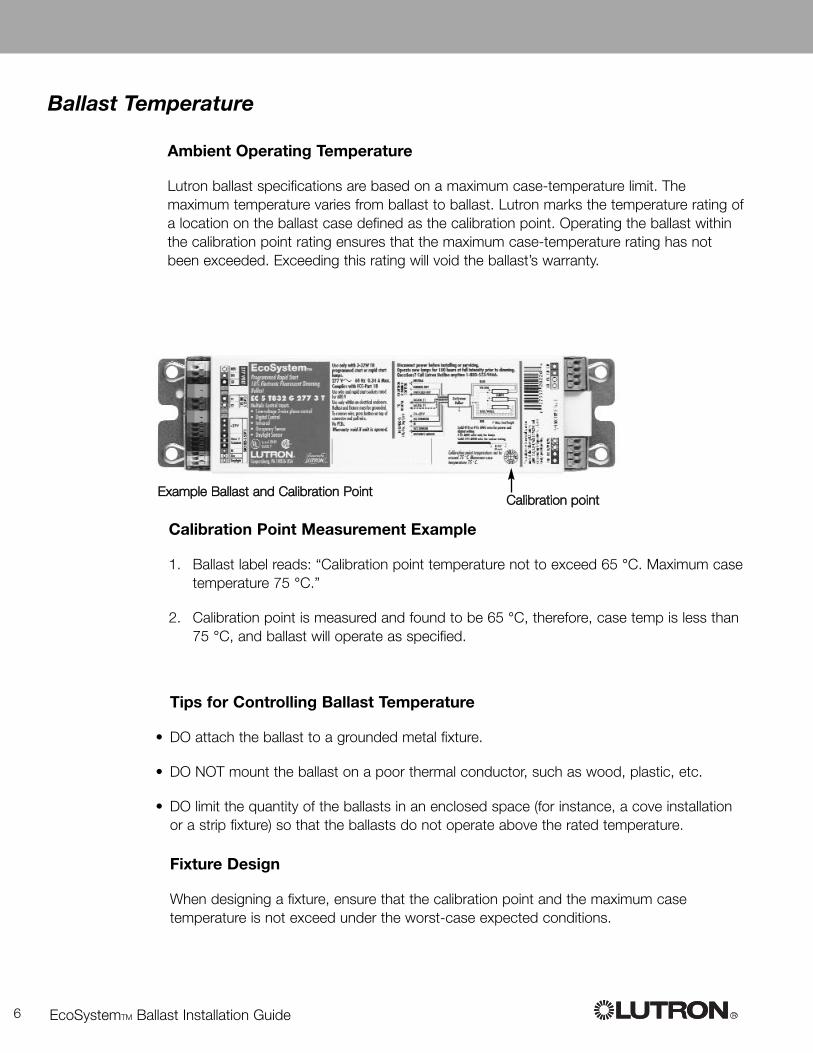
Calibration Point Measurement Example
1. Ballast label reads: “Calibration point temperature not to exceed 65 °C. Maximum casetemperature 75 °C.”
2. Calibration point is measured and found to be 65 °C, therefore, case temp is less than75 °C, and ballast will operate as specified.
EcoSystemTM Ballast Installation Guide R6
CCaalliibbrraattiioonn ppooiinntt
Ballast Temperature
Ambient Operating Temperature
Lutron ballast specifications are based on a maximum case-temperature limit. Themaximum temperature varies from ballast to ballast. Lutron marks the temperature rating ofa location on the ballast case defined as the calibration point. Operating the ballast withinthe calibration point rating ensures that the maximum case-temperature rating has notbeen exceeded. Exceeding this rating will void the ballast’s warranty.
Tips for Controlling Ballast Temperature
• DO attach the ballast to a grounded metal fixture.
• DO NOT mount the ballast on a poor thermal conductor, such as wood, plastic, etc.
• DO limit the quantity of the ballasts in an enclosed space (for instance, a cove installationor a strip fixture) so that the ballasts do not operate above the rated temperature.
Fixture Design
When designing a fixture, ensure that the calibration point and the maximum casetemperature is not exceed under the worst-case expected conditions.
EExxaammppllee BBaallllaasstt aanndd CCaalliibbrraattiioonn PPooiinntt
Technical Support: +1.800.523.9466 – www.lutron.com/ecosystem 7R
Control Methods
Lutron offers a variety of ways to control EcoSystem ballasts. Depending on the type ofroom or facility, a combination of sensors and wallstations can be used to control thefixtures.
EcoSystem Bus
The EcoSystem Bus enables you to connect a ballast to other EcoSystem ballasts and aBus Supply to create a system of up to 64 ballasts. Any sensor or wallstation connectedto an EcoSystem ballast can communicate with any or all fixtures on the EcoSystem Busto form a subsystem. Subsystems are configured and programmed using the handheldEcoSystem Programmer.
Standard 3-Wire Control
This is high voltage dimming from a traditional Lutron dimmer. Ballasts controlled by thismethod require three input wires: switched hot, dimmed hot, and neutral. The switchedhot and neutral provide power to the ballast. The dimmed hot provides a line voltagedimming signal from the control to the ballast. EcoSystem digital inputs to the ballast (E1and E2) must be provided as well. 3-wire dimming inputs cannot be grouped via theEcoSystem programmer, only ballasts hardwired to a 3-wire dimmer will be controlled bythe 3-wire dimmer.
NOTE: Digital wiring and 3-wire input can be used simultaneously (for example,automatic digital control and manual control through a “local” dimmer.
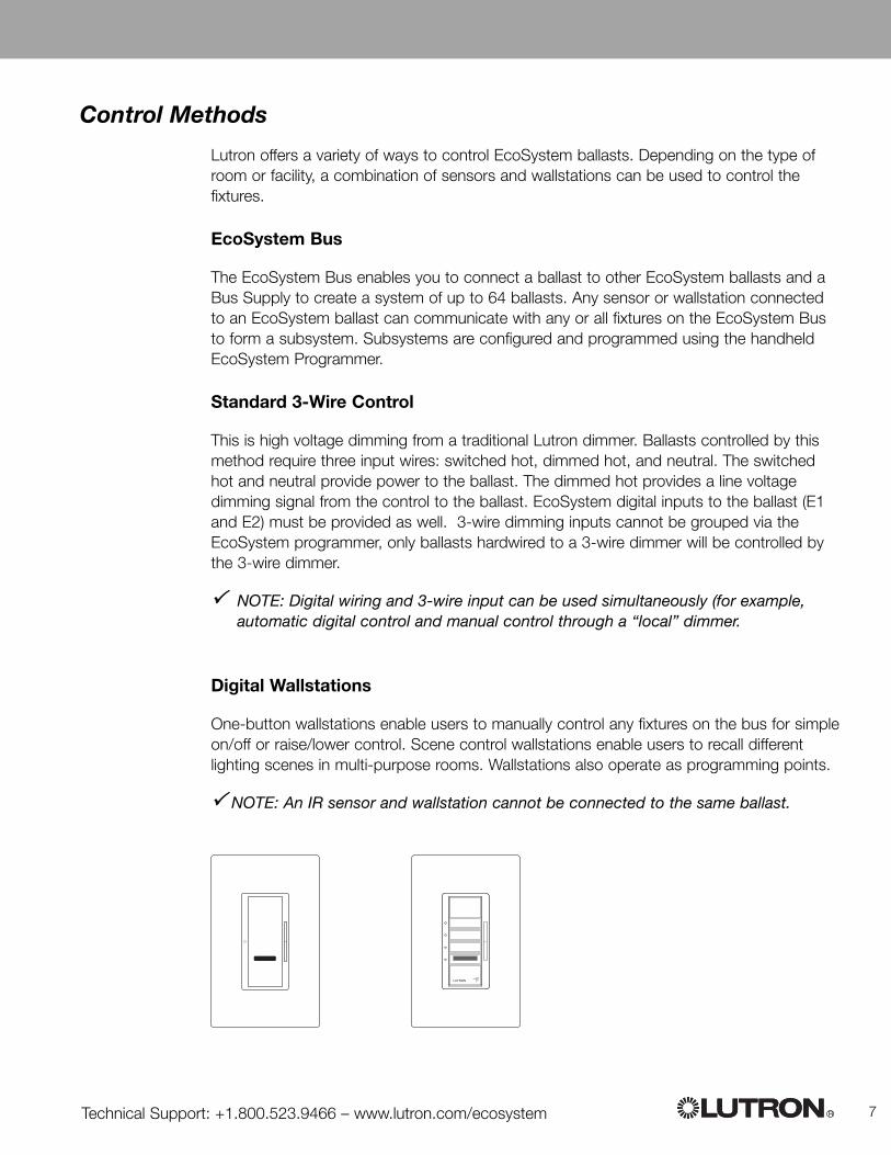
Digital Wallstations
One-button wallstations enable users to manually control any fixtures on the bus for simpleon/off or raise/lower control. Scene control wallstations enable users to recall differentlighting scenes in multi-purpose rooms. Wallstations also operate as programming points.
NOTE: An IR sensor and wallstation cannot be connected to the same ballast.

EcoSystemTM Ballast Installation Guide R8 R
Infrared (IR) receiver
Provides personal control via an IR remote. The receiver wires directly to the ballast. Itallows control an individual fixture or group of fixtures. It can be used as a programmingport to program the system.
EcoSystem Bus Supply
The EcoSystem Bus Supply powers the communication bus between devices, and iscapable of supporting a network of up to 64 ballasts or ballast modules, 32 occupantsensors, a combination of 64 wall controls and infrared (IR) receivers, and 8 daylightsensors.
Occupant sensor
Automatically turns lights off in assigned fixtures when the space is unoccupied.
Daylight sensor
Designed to harvest natural light and maintain specific light levels in the space, the sensorautomatically dims the lights when the available daylight is high or brightens the lightswhen the daylight is low. The sensor can control an individual fixture or a group of fixtures.In addition, the entire system can be programmed through the daylight sensor’s integratedinfrared receiver.

Step by Step:Installing and Wiring an EcoSystemTM
Dimming Ballast
This section lists the typical workflow followed to mount and wire an EcoSystem ballast.This section also describes the procedures needed to perform each step. If you areinstalling a fixture that is already mounted and partially wired, you will not need to performall of the steps.
NOTE: If you have not already done so, refer to “Before You Get Started: ImportantInformation About EcoSystem Ballasts” on page 2.
Typical Workflow
Listed below is the typical workflow followed to mount and wire an EcoSystem ballast.
CAUTION:Make sure the circuit breaker to all components is turned OFF before performing anywiring.
1. Mount the ballast.
2. Wire the lamp sockets.
3. Wire the ballast to the lamp sockets.
4. Connect line voltage (distribution panel or dimmer).
5. Connect the EcoSystem Bus.
6. Connect a wallstation.
7. Connect a daylight, occupant, and/or infrared sensor.
8. Mount the lamps.
9. Test the ballast.
Refer to the following pages for detailed procedures on how to perform each step.
2
Technical Support: +1.800.523.9466 – www.lutron.com/ecosystem 9R

EcoSystemTM Ballast Installation Guide R10
CAUTION:
• Ballasts generate heat and musthave a way to dissipate it. This isdone by thermal conduction to thefixture.
• Screws, knockouts, dimples, orfeatures that raise the ballast off thefixture (even slightly) are notacceptable since they impair theballast’s ability to dissipate heat.
• Do not mount the ballast on thefixture cover plate that holds thelamps. This mounting location isoften the hottest point on the fixture.
Mounting the Ballast
To mount the ballast in the fluorescent fixture, use two screws to secure it to thefixture or 1 screw and a crow’s foot. The ballast MUST be mounted flush to the fixturealong its entire length.
Use “star-type” screws, washers, or nuts to penetrate the paint finish on the ballast andground both the fixture and the ballast to the earth ground. Attach both ends of the ballastto the fixture to ensure proper grounding.
MMeettaall ffiixxttuurree
BBaallllaasstt MMUUSSTT bbee mmoouunntteedd fflluusshh ttoo tthhee ffiixxttuurreeaalloonngg iittss eennttiirree lleennggtthh
BBaallllaasstt
OOKK
NNoo
NNoo
NNoo
SSttaarr--ttyyppee wwaasshheerr ddeessiiggnneedd ttooppeenneettrraattee ppaaiinntt ffiinniisshh

Technical Support: +1.800.523.9466 – www.lutron.com/ecosystem 11R
CAUTION:
• Make sure the circuit breaker to the ballast is OFF before wiring.
• Use only rapid-start rotary locking, slide-in, or knife-edge sockets.
Wiring the Lamp Sockets
To wire lamp sockets, refer to the following illustrations for one-lamp, two-lamp,three-lamp, and U-bend fixtures.
Ballast Dimensions
Two different EcoSystem Ballast Sizes are used. Follow the guides below formounting. “G” or “J” in the model number of the ballast (prior to the ballast voltage)indicates ballast dimensions.
G Can DimensionsA = 9.5'' (241 mm)B = 8.9'' (226 mm)C = 7.1'' (180 mm)D = 1.00'' (25 mm)E = 2.38'' (60 mm)
AA
EE
DDCC
AABB
CC EEDD
FF
J Can DimensionsA = 18.0'' (457 mm)B = 17.68'' (449 mm)C = 6.82'' (173 mm)D = .39'' (10 mm)E = 1.0'' (25 mm)F = 1.18'' (30 mm)
G Can Outline
J Can Outline
BB

EcoSystemTM Ballast Installation Guide R12
U-Bend Lamp Socket Wiring
3-Lamp Socket Wiring
RReedd
YYeellllooww
BBlluuee
RReedd
2-Lamp Socket Wiring
YYeellllooww
BBlluuee
RReedd
YYeellllooww BBlluuee
SSttrriippeedd
RReedd
1-Lamp Socket Wiring
BBlluuee

Technical Support: +1.800.523.9466 – www.lutron.com/ecosystem 13R
Wiring to Three Lamps (G can shown)
CAUTION:
• Make sure the circuit breaker to the ballast is OFF before wiring.
• Lead lengths from ballast to socket must not exceed 7 ft (2.1 m) for T8 lamps.
BLUBLU
REDRED
YELYEL
N/CN/C
Wiring to Two Lamps (G can shown)
BLUBLU
REDRED
YELYEL
B/WB/W
Wiring the Ballast to the Lamp Sockets
To wire the ballast to the lamp sockets, refer to label on the dimming ballast. Imagesbelow are for reference only.
BLUBLU
REDRED
Wiring to One Lamp (J can shown)

EcoSystemTM Ballast Installation Guide R14
Connecting the Line Voltage (Distribution Panel)
To wire the line voltage from the distribution panel, wire the hot and neutralconductors from the distribution panel to the ballast terminals labeled HOT and NEU.
Wire color designations for line voltage terminals on the ballast are:
• White = neutral
• Black = hot (mains)
NOTE: Mains Voltage must match voltage specified on the ballast label.
Connecting the Line Voltage (Dimmer or Dimming Panel)
To wire the line voltage from a dimmer or dimming panel, wire the switched hot,dimmed hot, and neutral conductors from the dimming panel or dimmer to the ballastterminals as shown.
CCAAUUTTIIOONN:
• Make sure the circuitbreaker at the distributionpanel is OFF beforewiring.
• The ballast terminals holdonly one #18 _ #16 AWG (1.02 _ 1.29 mm) solidwire.
E1E2
NEU
HOTDH
277 V~Class 2
Bus
E1E2
NEU
HOTDH
277 V~Class 2
Bus
LUTRONLUTRON
Line voltageNeutral - WhiteHot - Black
BBaallllaasstt TTeerrmmiinnaallss
OOrraa
nnggee
((DDHH
))
RReedd
YYeellllooww
WWhhiittee
GGrreeeenn
GGrroouunndd
BBllaa
cckk ((HH
OOTT))
WWhhii
ttee ((NN
EEUU))
Technical Support: +1.800.523.9466 – www.lutron.com/ecosystem 15R
CAUTION:
• Make sure the circuit breaker to the ballast isOFF before wiring.
• Ballast terminals hold only one #16 _ #18 AWGsolid wire. In most cases, a wire connection tothe EcoSystem bus is required.
• Follow all applicable local and national codes.
E1E2
NEU
HOTDH
277 V~Class 2
Bus
E1E2
NEU
HOTDH
277 V~Class 2
Bus
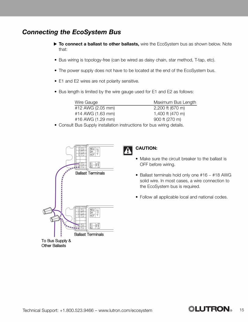
Connecting the EcoSystem Bus
To connect a ballast to other ballasts, wire the EcoSystem bus as shown below. Notethat:
• Bus wiring is topology-free (can be wired as daisy chain, star method, T-tap, etc).
• The power supply does not have to be located at the end of the EcoSystem bus.
• E1 and E2 wires are not polarity sensitive.
• Bus length is limited by the wire gauge used for E1 and E2 as follows:
Wire Gauge Maximum Bus Length#12 AWG (2.05 mm) 2,200 ft (670 m)#14 AWG (1.63 mm) 1,400 ft (470 m)#16 AWG (1.29 mm) 900 ft (270 m)
• Consult Bus Supply installation instructions for bus wiring details.
TToo BBuuss SSuuppppllyy &&OOtthheerr BBaallllaassttss
BBaallllaasstt TTeerrmmiinnaallss
BBaallllaasstt TTeerrmmiinnaallss

EcoSystemTM Ballast Installation Guide R16
Connecting Sensors and Wallstations
To connect a daylight sensor, occupant sensor, wallstation and/or infraredreceiver, refer to the instruction sheets provided with the devices. Diagrams for the Class2 Sensor/Wallstation terminals are shown below.
NOTE: The ballast accepts only one infrared input (either daylight sensor, IR sensor orWallstation).
G Can Class 2 Sensor Terminals
+20V
Day
light
IRCom
mon
Class 2(#22 AWG Solid)
Occ
J Can Class 2 Sensor Terminals
+20 V (Red)Common (Black)IR (White)Occ (Blue)Daylight (Yellow)
+20 V (Red)Common (Black)IR (White)Occ (Blue)Daylight (Yellow)
+20V
DaylightOccIR
Common
Class 2 (#22 AW
G S
olid)
E2E1
Class 2
Bus
DHNEU
277 VoltSH
Technical Support: +1.800.523.9466 – www.lutron.com/ecosystem 17R
RReedd
YYeellllooww
BBlluuee
FFlluuoorreesscceenntt llaammpp
MMoouunnttiinngg hheeiigghhtt
GGrroouunnddeedd mmeettaall
TTwwoo mmoouunnttiinngg sslloottss
LLaammpp ssoocckkeett ((ssiiddee vviieeww))
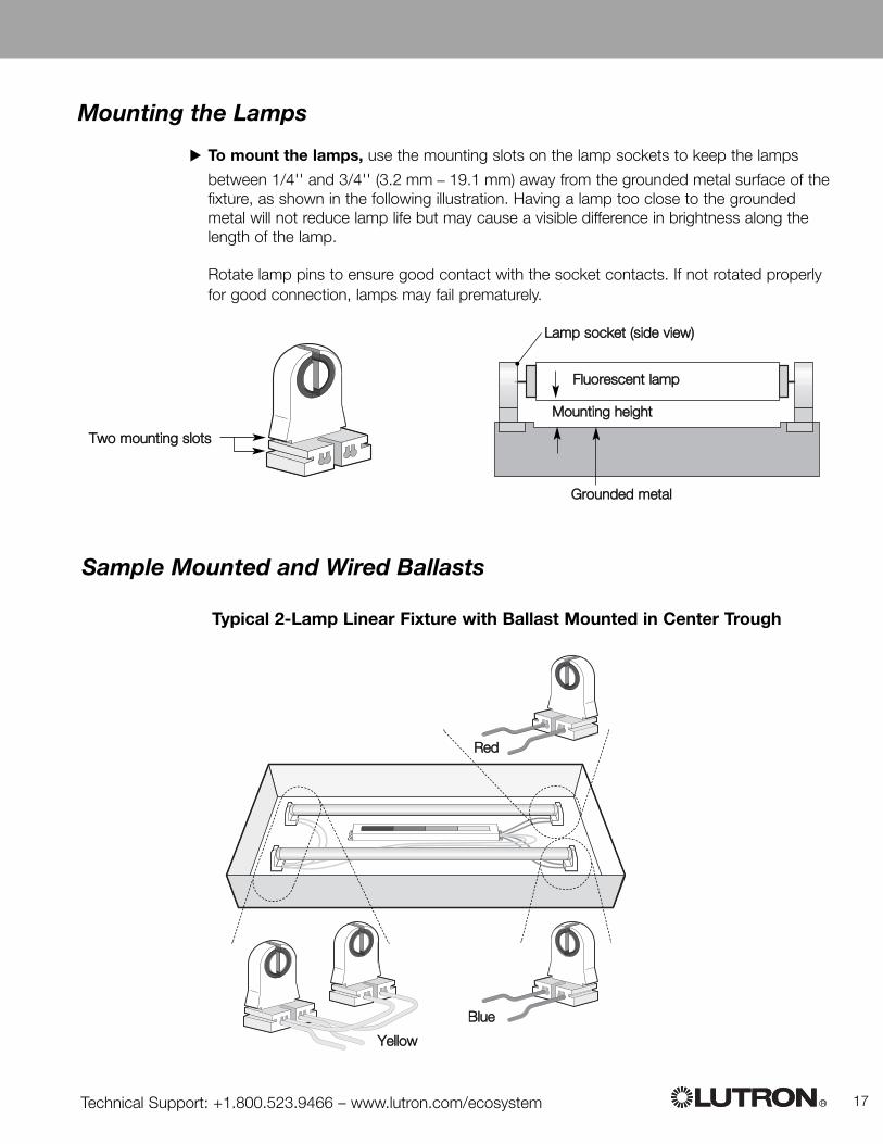
Sample Mounted and Wired Ballasts
Typical 2-Lamp Linear Fixture with Ballast Mounted in Center Trough
Mounting the Lamps
To mount the lamps, use the mounting slots on the lamp sockets to keep the lamps
between 1/4'' and 3/4'' (3.2 mm _ 19.1 mm) away from the grounded metal surface of thefixture, as shown in the following illustration. Having a lamp too close to the groundedmetal will not reduce lamp life but may cause a visible difference in brightness along thelength of the lamp.
Rotate lamp pins to ensure good contact with the socket contacts. If not rotated properlyfor good connection, lamps may fail prematurely.

EcoSystemTM Ballast Installation Guide R18
EC 5T832 277 3L
RReedd
YYeellllooww
Typical 3-Lamp Linear Fixture with Ballast Mounted in Center Trough
BBlluuee
SSttrriippeedd

Technical Support: +1.800.523.9466 – www.lutron.com/ecosystem 19R
Testing the Ballast
To check the ballast after mounting and wiring, complete the following checklist.
Confirm all ballasts are properly wired, double check all mains inputs and EcoSystembus wires are properly terminated at the ballast. Confirm that the mains input voltage doesnot exceed ballast rated voltage. Terminate the EcoSystem Bus at the EcoSystem BusSupply. If the bus is not connected, the lamps will remain at full intensity.
Complete installation, confirm all fixtures and enclosures are properly closed, mounted,and grounded.
Power all ballasts, all lamps should strike to full light output.
If any ballasts fail to strike lamps, confirm mains wiring to the ballast is correctlyconnected and of the appropriate voltage.
If lamps strike, drop out, or continue to flash, disconnect power and inspect ballast tolamp socket wiring. All wiring should match the wiring diagram on the ballast case.
Confirm proper dimming, follow the instructions with the EcoSystem Bus Supply tomanually override all ballast light levels to low end, off, and back to high end. If any ballastsdo not react to the override commands, check EcoSystem Bus wiring and that theEcoSystem Bus Supply is powered and connected.
Notice:Consult lamp manufacturer for lamp seasoning requirements prior to dimming

EcoSystemTM Ballast Installation Guide R20
Ballast Warranty
World HeadquartersLutron Electronics Co., Inc.7200 Suter RoadCoopersburg, PA 18036-1299USA
TEL +1-610-282-3800FAX +1-610-282-12431-800-523-9466 (USA,CANADA)[email protected]@lutron.com
European HeadquartersLutron EA Ltd.Lutron House, 6 SovereignClose,London E1W 3JF, UK
TEL +44(0)20-7702-0657FAX +44(0)20-7480-6899FREEPHONE [email protected]
Spain, MadridTEL +34-91-567-8479FAX +34-91-567-8478
Spain, BarcelonaTEL +34-93-4965-742FAX [email protected]
FranceTEL +33-(0)1-44-70-71-86FAX +33-(0)[email protected]
GermanyTEL +49-309-710-4590FAX [email protected]
JapanTEL +81-3-5405-7333FAX [email protected]
Hong KongTEL +852-2104-7733FAX [email protected]
SingaporeTEL +65-6220-4666FAX [email protected]
LUTRON ELECTRONICS CO., INC.
BALLAST THREE YEAR LIMITED WARRANTY
For a period of three years from the date of shipment by Lutron, Lutron warrants each newballast to be free from manufacturing defects. Lutron will, at its option, repair or provide acomparable replacement for any defective ballast that, in Lutron's opinion, has been installedand operated under pursuant to Lutron's product specifications and the applicable provisionsof the National Electrical Code and of the Safety Standards of Underwriters Laboratories solong as Lutron is promptly notified of the defect within the three year warranty period and, ifrequested by Lutron, the ballast, is returned to Lutron.
This warranty is in lieu of all other express warranties and of all implied warranties,including implied warranties of merchantability and of fitness for a particular purpose.This warranty does not cover: the cost of installation, removal or reinstallation; damageresulting from misuse, abuse, or improper or incorrect repair; damage from improperwiring or installation; or incidental or consequential damages. Lutron's liability on anyclaim for damages arising out of or relating to the manufacture, sale, installation,delivery, or use of the ballast is limited to the purchase price of the ballast.
No Lutron agent, employee or representative has any authority to bind Lutron to anyaffirmation, representation or warranty concerning the ballast. Unless an affirmation,representation or warranty made by an agent, employee or representative is specificallyincluded herein, or in standard printed materials provided by Lutron, it does not form apart of the basis of any bargain between Lutron and customer and will not in any waybe enforceable by customer.
In no event will Lutron or any other seller be liable or responsible for any (i) consequential orspecial damages, (ii) repair work undertaken without Lutron's prior consent, (iii) ancillaryequipment not furnished by Lutron which is attached to or used in connection with theballast, all such equipment being expressly excluded from this warranty, or (iv) damage to theballast resulting from the use of ancillary equipment not furnished by Lutron for use with theballast.
This warranty provides specific legal rights. Other rights, which vary from state to state, mayexist. Some states do not allow limitations on how long an implied warranty lasts or theexclusion or limitation of incidental or consequential damages, so the above limitations orexclusions may not apply.
Contact the Lutron Technical Support Center at the numbers provided below or your localLutron sales representative with questions concerning the installation or operation of acovered ballast or this Warranty, or to make a warranty claim. Please provide the exact modelnumber when calling.
USA and Canada (24 hrs/7days) Technical Support +1.800.523.9466Other countries (8 a.m. - 8 p.m. ET) Technical Support +1.610.282.3800http://www.lutron.com/ecosystem
Lutron is a registered trademark, and EcoSystem is a trademark of Lutron Electronics Co.,Inc. NEC is a registered trademark of the National Fire Protection Association, Quincy, MA.
These products may be covered under one or more of the following U.S. patents: 6,452,344,6,674,248, and corresponding foreign patents. U.S. and foreign patents pending.
©2006 Lutron Electronics Co., Inc